laying the groundwork for bonding the grounds: … · 1 laying the ‘groundwork’ for bonding the...
TRANSCRIPT

1
Laying the ‘Groundwork’ for Bonding the Grounds:
Fundamentals and techniques ‘grounded’ in good science and bitter experience.
ATIS Protection Engineer’s Group (PEG) 2017 March 14 - 16, 2017 Dallas, TX
Dan McMenamin
President Dan McMenamin and Associates
63 Tattersall Drive
West Deptford, New Jersey 08051-1712 (USA)
+1 (215) 880-2488
Abstract The world of technology is blackened by carbon char that began electronic life as semiconductor material. Worse
yet, a good many personal shock hazards to persons and animal life exist ‘out there’ from energized manhole
covers, metal utility poles and other infrastructure.
Bonding and Grounding are critical components within the realm of electrical protection, together with surge
protective devices and other intentional means designed into infrastructures that produce or conduct unwanted
potentials, whether by lightning, electrical fault or energy surge. The purpose of this paper and presentation is to
provide a structured basis upon which to make necessary decisions about when and how to bond and ground
various equipment elements including buildings and huts, electronic equipment enclosures, transmission and
communications towers, centralized and distributed antenna systems, and small cell deployments. Although surge
protective devices will be mentioned in passing, the focus of this paper is bonding and grounding
Bonding
Although the most commonly used terms for electrical protection is grounding, in general terms, bonding is,
perhaps the most effective means of protection from shock or from thermal damage caused by flashover arcing.
Bonding is an intentional low impedance intentional connection between two conductive materials. Bonding
reduces the difference in potential (voltage) that might exist between them if a conductive element becomes
energized in a fault condition or lightning strike.
The word impedance is used in the paragraph above to differentiate it from resistance. Although both terms are
expressed in ohms, the impedance of a conductor can vary significantly by the frequency or the rise time of the
energy carried by a conductor and the inductance of the conductor.
Inductance is a function of the length of a conductor and the radius of physical bends to the conductor. The cross-
sectional area of a conductor also influences impedance but only to a small extent. A conductor with a dc
resistance of less than one (1) ohm might easily have tens of thousands of ohms of impedance. Due to a high
impedance, electrical contact with some source with a high frequency or a sharp rise time such as a lightning strike
could have a very large shock potential to someone.
A key objective in bonding is to protect living beings from electrical shock if juxta-positioning of their body places
them into contact with more than one conductive element when one of them could become energized with
respect to another. A protective design objective is to limit unwanted voltages that might be ‘seen’ across

2
electronic systems. While as little as fifty (50) volts can damage sensitive electronics in digital circuitry, voltages as
low as three (3) can cause bit errors that degrade digital system performance and reliability.
Figure 1 is a graphic representation of typical voltages that can cause injury or malfunction to people, animals and
digital circuitry as is covered above. The most critical condition are voltages that conduct across cardiac muscle
because this organ functions by electrochemical processes subject to failure caused by external electrical stimuli.
Figure 1: unwanted voltage perturbations of sufficient amplitude across a body or a circuit can cause malfunction, damage or complete destruction.
Fences
An example of the bonding principal could be an intentional bond wire between a tower leg and a fence nearby
enough that someone might be in contact with both items when the tower was struck by lightning.
Figure 4: The photo on the left is of a cell site with very little space between the tower and a fence. The sketch on the right shows that people visiting the site could become into contact with both the tower and the fence. A lightning strike or ground potential rise to either conductive element could pass through the body of a person, placing them at risk of cardiac anomaly or burn injury. In most bonding and grounding codes and

3
standards, six (6) feet (1m) is the separation distance at or below which, bonding is needed. The Six feet metric is considered the span of someone’s arms that could be in contact with the conductive elements.
Further, fences can become an electrical hazard when they run parallel to nearby or overhead high tension power
lines. Voltage becomes induced into the metal parts of the fence.
Still further, fences run along the paths of buried utility lines also can become energized. Electric utilities deploy
underground wiringi that has concentric Neutral leads, typically for 12.5/7.2 kV (15 kV rated) and 24.9/14.4
kV (25 kV rated) underground distribution systems with solidly multi-grounded neutrals. Figure 5 is a sketch of this
kind of cable. The inner conductor is either copper or aluminum. This conductor is protected by insulation and by
inner and outer shields as is shown. Surrounding the insulation shield are strands of conductor that will carry
Neutral (aka return) current. Protecting the concentric Neutral is a plastic jacket.
For several years, some utilities deployed concentric Neutral cabling that did not have a jacket. The Neutral
conductors were exposed to soil in the trenches where they lie buried. In time, many of these Neutral conductors
went ‘open’ due to corrosion damage. When these conductors failed, Neutral current traveled in soil, along fence
lines, and along the shields of telephone cables collocated in the trench.
Figure 5: Concentric Neutral cable as is used by electric utilitiesii for buried applications.
Such voltages can be high enough to cause serious electrical shocks to people at gates because electrically, the
fence is a conductor and the gate ‘looks’ like a single pole switch. When someone opens a gate, he or she opens
the electrical path along the fence and if they are in contact with both sides of the gate, they become the path for
the induced potential. The problem becomes more acute with double gate arrangements because it’s more likely
that the person would have a hand on each gate when opening it.

4
Figure 6: Long fence runs parallel with high tension lines tend to pick up induced energy, sometimes at levels that can injure people at gates. Likewise, fences accidentally carrying current from failed Neutral leads in buried cabling also can become lethal at gates.
Figure 6a: Bonding around the gate and gate to post is important to avoid electrical shock.
5
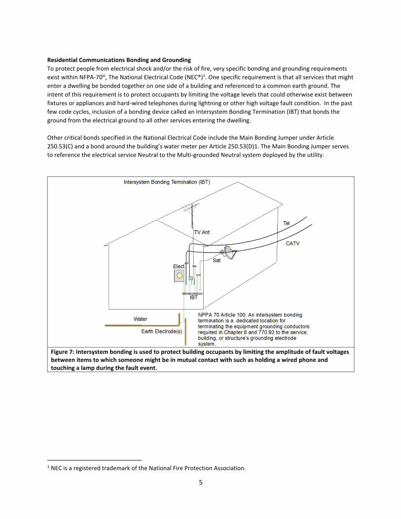
Residential Communications Bonding and Grounding
To protect people from electrical shock and/or the risk of fire, very specific bonding and grounding requirements
exist within NFPA-70iii, The National Electrical Code (NEC®)1. One specific requirement is that all services that might
enter a dwelling be bonded together on one side of a building and referenced to a common earth ground. The
intent of this requirement is to protect occupants by limiting the voltage levels that could otherwise exist between
fixtures or appliances and hard-wired telephones during lightning or other high voltage fault condition. In the past
few code cycles, inclusion of a bonding device called an Intersystem Bonding Termination (IBT) that bonds the
ground from the electrical ground to all other services entering the dwelling.
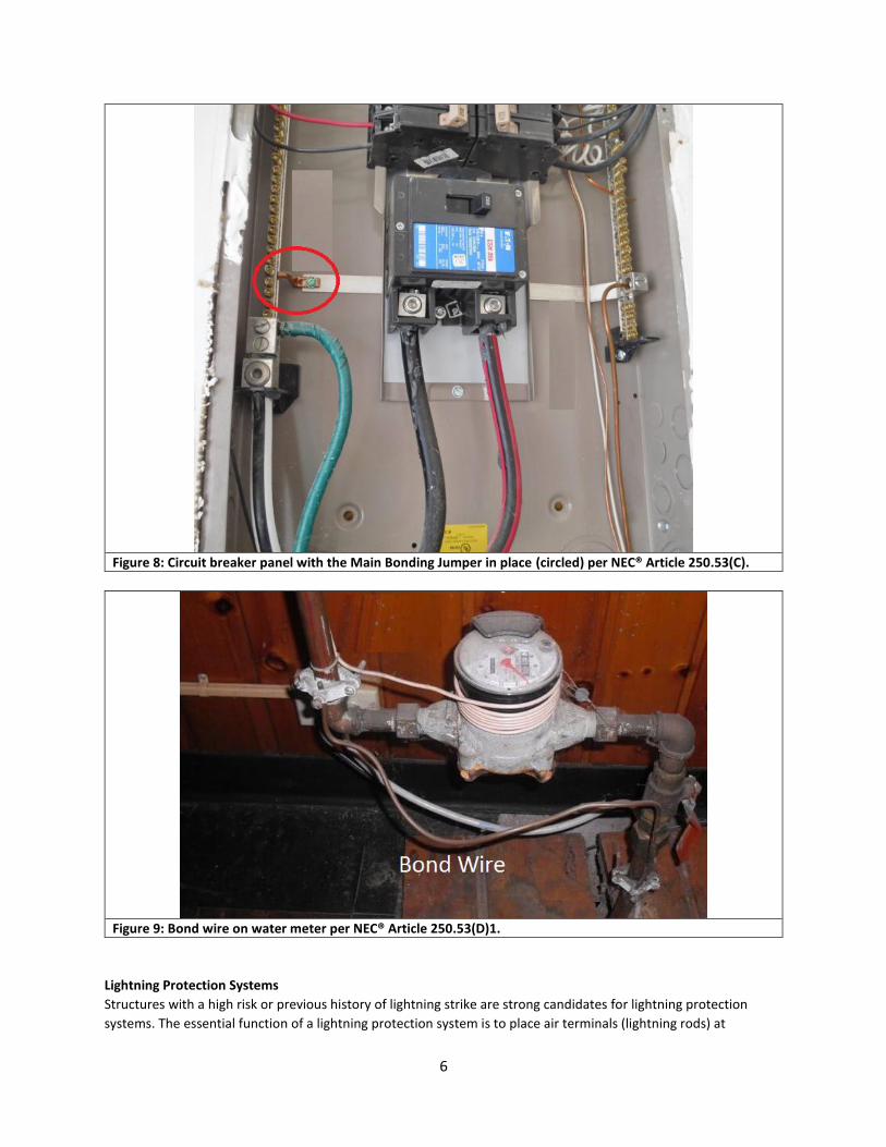
Other critical bonds specified in the National Electrical Code include the Main Bonding Jumper under Article
250.53(C) and a bond around the building’s water meter per Article 250.53(D)1. The Main Bonding Jumper serves
to reference the electrical service Neutral to the Multi-grounded Neutral system deployed by the utility.
Figure 7: Intersystem bonding is used to protect building occupants by limiting the amplitude of fault voltages between items to which someone might be in mutual contact with such as holding a wired phone and touching a lamp during the fault event.
1 NEC is a registered trademark of the National Fire Protection Association.
6
Figure 8: Circuit breaker panel with the Main Bonding Jumper in place (circled) per NEC® Article 250.53(C).
Figure 9: Bond wire on water meter per NEC® Article 250.53(D)1.
Lightning Protection Systems
Structures with a high risk or previous history of lightning strike are strong candidates for lightning protection
systems. The essential function of a lightning protection system is to place air terminals (lightning rods) at

7
mathematically strategic locations on a roof or other structures and then bond those air terminals to earth
electrodes via at least two low impedance paths for the unwanted current. There is a common misunderstanding
that such systems attract lightning, when in fact, they simply shunt the energy around the structure, safely to the
earth. Without the protection, the structure itself would be struck and suffer damage.
In addition to the air terminals, a lightning protection also includes extensive bonding of items like electrical
panelboards, water heaters, metal siding, piping systems, metal items on the roof such as vent stacks, antennae,
solar panels and the like. Guidance for lightning protection systems may be found in NFPA 780 iv and UL 96Av.
Most mistakes in lightning protection occur when items are added to the building without regard for inclusion into
the system. The most common mistakes include adding antennae, security cameras, lights etc. that are taller than
the lightning rods. Lightning rods should be at least 10 inches (25 cm) taller than any metal in the vicinity.
Telecommunications Outside Plant
The telecommunications industry employs bonds and grounds to protect outside plant cables exposed to lightning
or electrical faults caused by accidental contact with utility power conductors. In these cases, cable sheaths are
bonded both to the earth and (if present) grounds that serve as part of the utility Multi-Grounded Neutral (MGN)
system. Outdoor telecommunications and electric utility cabling are governed by the National Electrical Safety
Code.vi Most wireline telephone companies also follow the precepts of Telcordia TR-NWT-001075 Generic
Requirements for Outside Plant Bonding and Grounding Systems Hardware. vii
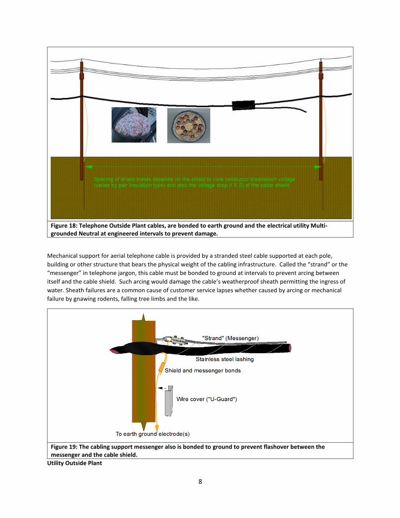
By bonding telephone cable electrostatic shields to earth ground at intervals, the cables are protected from
flashover arcing between the electrostatic shield and communications conductors within the cable’s core.
Exothermic heat of arcing results in insulation breakdown of the communications conductors.
Figure 17: Insulation type is part of the calculation used to perform calculations that determine bonding intervals.
8
Figure 18: Telephone Outside Plant cables, are bonded to earth ground and the electrical utility Multi-grounded Neutral at engineered intervals to prevent damage.
Mechanical support for aerial telephone cable is provided by a stranded steel cable supported at each pole,
building or other structure that bears the physical weight of the cabling infrastructure. Called the “strand” or the
“messenger” in telephone jargon, this cable must be bonded to ground at intervals to prevent arcing between
itself and the cable shield. Such arcing would damage the cable’s weatherproof sheath permitting the ingress of
water. Sheath failures are a common cause of customer service lapses whether caused by arcing or mechanical
failure by gnawing rodents, falling tree limbs and the like.
Figure 19: The cabling support messenger also is bonded to ground to prevent flashover between the messenger and the cable shield.
Utility Outside Plant
9
As is the case with telephone company aerial cables, arcing flashover can cause harm to people working on the
pole or significant damage to the physical plant. Thus, the separation distances between phase wires, catenary
wires and Ground conductors needs to withstand lightning strikes to avoid backflash arcing. The surge impedances
of the wiring, soil and other factors are used to calculate safe separation clearance. Also, the type and number of
insulator disks also is factored into the calculations.
Lightning is a major causes of sudden line outages. Lightning generates traveling waves on overhead conductors,
that travel to different devices connected to both sides of line. These high energy waves represent a dangerous
condition for line insulators and equipment insulation connected to that line.
Lightning return-stroke current and the charge energy delivered by the stroke are the most important parameters
to assess the severity of lighting strokes on power lines and support apparatus. The lightning damages a power
apparatus in two ways:
• The high-energy wave raises the voltage across the apparatus such that the terminals across the struck
apparatus spark over causing a short circuit of the system or the voltage punctures through the apparatus
electrical insulation, causing permanent damage.
• The energy of the lightning stroke may exceed the withstand capability of the apparatus, causing
meltdown or fracture.
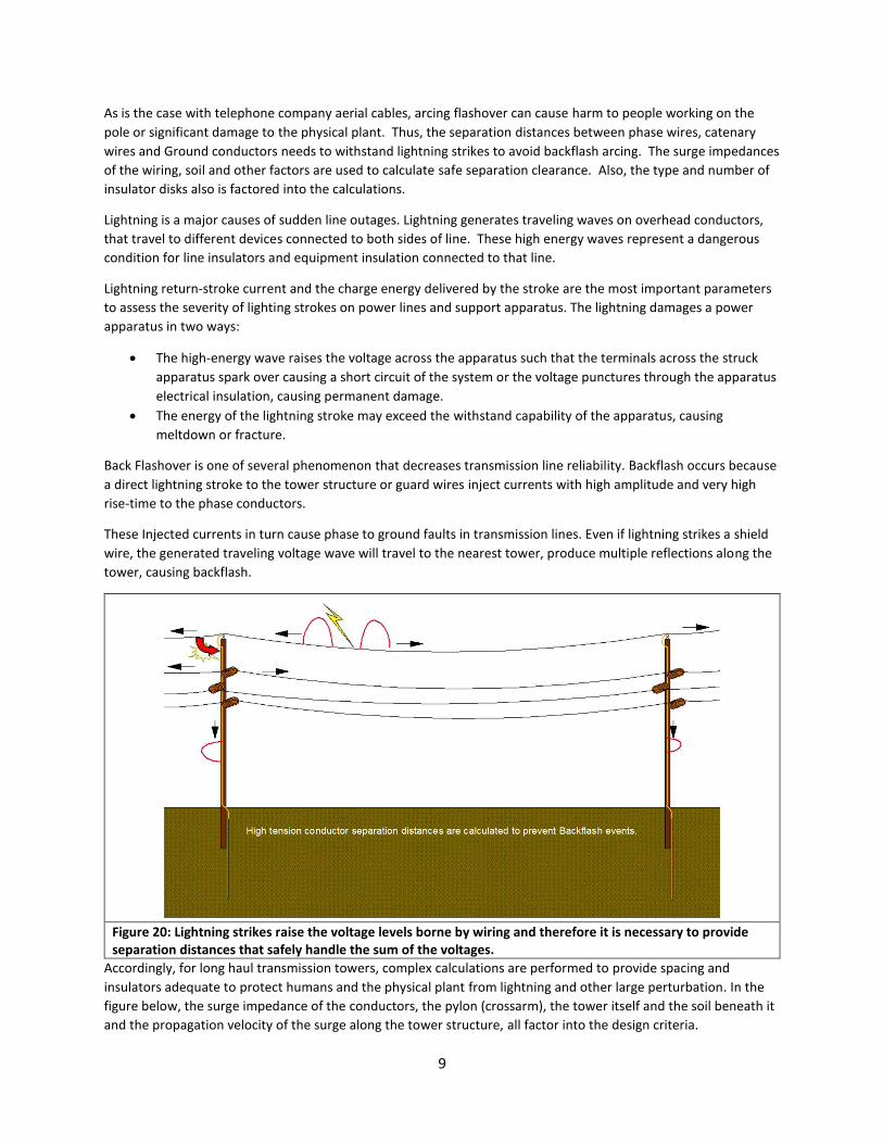
Back Flashover is one of several phenomenon that decreases transmission line reliability. Backflash occurs because
a direct lightning stroke to the tower structure or guard wires inject currents with high amplitude and very high
rise-time to the phase conductors.
These Injected currents in turn cause phase to ground faults in transmission lines. Even if lightning strikes a shield
wire, the generated traveling voltage wave will travel to the nearest tower, produce multiple reflections along the
tower, causing backflash.
Figure 20: Lightning strikes raise the voltage levels borne by wiring and therefore it is necessary to provide separation distances that safely handle the sum of the voltages.
Accordingly, for long haul transmission towers, complex calculations are performed to provide spacing and
insulators adequate to protect humans and the physical plant from lightning and other large perturbation. In the
figure below, the surge impedance of the conductors, the pylon (crossarm), the tower itself and the soil beneath it
and the propagation velocity of the surge along the tower structure, all factor into the design criteria.

10
Figure 21 Lightning may strike power lines or the towers that support them. It is important to prevent living beings and infrastructure from harm. Touch and step potentials if large, can harm people or wildlife. One design goal is to design insulators that will withstand voltage excursions that could appear across them. Another goal is to control surge impedance in the tower and design an adequate earth electrode system.
Substations
A utility substations is a facility consisting of transformers, protection circuits, switching apparatus and other
infrastructure that convey electricity from generating sites to consumers. Depending on the system, a substation
might connect high tension lines of 500KV or more to so-called ‘Medium voltage’ lines, typically 15KV or 24KV, for
distribution into communities.
Bonding and grounding design criteria for substations is similar to that of high tension transmission towers,
however a broader buried metallic mesh grid is provided for the site. A typical substation is shown in Figure 22
below. Note the air terminals (lightning rods) at the top of the structures.

11
Figure XX Typical substation copper grid and bonding arrangement (Courtesy Pentair Corporation).
Figure XY Welded REBAR used as a reference grid.
12
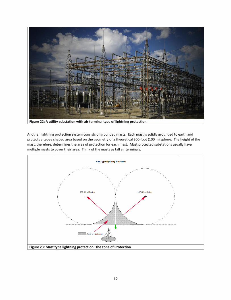
Figure 22: A utility substation with air terminal type of lightning protection.
Another lightning protection system consists of grounded masts. Each mast is solidly grounded to earth and
protects a tepee shaped area based on the geometry of a theoretical 300-foot (100 m) sphere. The height of the
mast, therefore, determines the area of protection for each mast. Mast protected substations usually have
multiple masts to cover their area. Think of the masts as tall air terminals.
Figure 23: Mast type lightning protection. The zone of Protection
13
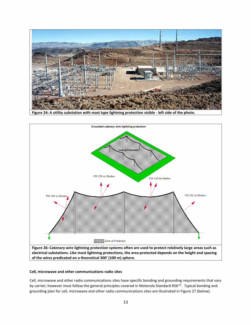
Figure 24: A utility substation with mast type lightning protection visible - left side of the photo.
Figure 26: Catenary wire lightning protection systems often are used to protect relatively large areas such as electrical substations. Like most lightning protections, the area protected depends on the height and spacing of the wires predicated on a theoretical 300’ (100 m) sphere.
Cell, microwave and other communications radio sites
Cell, microwave and other radio communications sites have specific bonding and grounding requirements that vary
by carrier; however most follow the general principles covered in Motorola Standard R56viii. Typical bonding and
grounding plan for cell, microwave and other radio communications sites are illustrated in Figure 27 (below).

14
For reliability, soil resistance should be measured using 4-wire Wenner tests and groundfields engineered to meet
specific ohmic objectives. “Cookie cutter” groundfield designs are strongly discouraged because soil conditions
vary widely from location to location due to its composition (loam, clay, alluvium, sand, etc.), moisture content and
other factors. Buried rings should be custom designed and placed well below the frost line for the tower and the
shelter or equipment cabinet pads.
Due to rocky terrain and other factors, some locations present great difficulty in meeting ohmic design objectives
and therefore bonding becomes an even more critical aspect of system reliability.
Inline splices to lengthen conductors tend to degrade performance and are discouraged in most cases and
forbidden by some codes. Bond connections between conductors should made using devices that are U.L. listed for
the purpose or by exothermic welds.
Figure 27: Typical bonding and grounding plan for cell, microwave and other radio communications sites.
Transmission lines on towers need to be carefully bonded and any bends to enter a shelter or cabinetized
electronic system should have a tight bend radius. This fact is a design departure from typical grounding rules.
Bonding and grounding leads are subject to lightning, RF and other influences that are high frequencies or behave
like high frequency due to sharp rise-times of the wave front. Generally, long bend radii are important for such
leads because tight bend radii tend to drastically increase the impedance of the conductor to the high frequency
component of the interfering energy.

15
For transmission-lines such as waveguides, coaxial cables and composite cables for Remote Radio Heads, the
objective is to provide a low impedance to earth ground but a high impedance to the shelter or cabinet. The intent
is to minimize unwanted energy from entering the shelter or equipment cabinet. By placing a grounding kit on the
waveguide, coaxial cable and composite cable routed in a relatively straight path to earth Ground provides a low
impedance path in that direction. By making a 90-degree bend just beneath the grounding kit (See figure 28)
establishes a high impedance path toward the equipment. Because electricity follows the path of least resistance
(or impedance) most of the unwanted energy will follow the low impedance path and only a relatively small
amount will follow the high impedance path.
An additional grounding kit at the shelter or cabinet entrance and bonded wall hatches further reduce the level of
unwanted energy impinging on equipment.
Structured bonding and grounding within the shelter provide safety and reliability by minimizing the difference in
electrical potentials between network elements during lightning or other large perturbations.
Figure 28: Using conductor impedance to protect a facility from lightning energy.
16
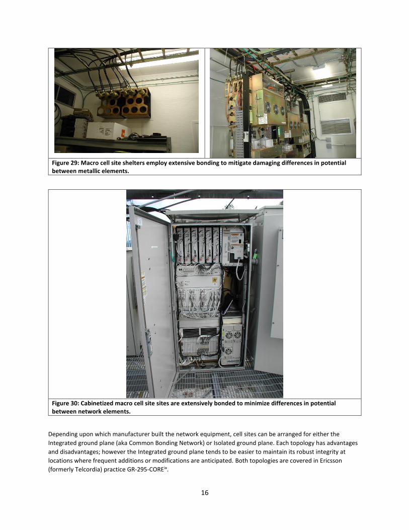
Figure 29: Macro cell site shelters employ extensive bonding to mitigate damaging differences in potential between metallic elements.
Figure 30: Cabinetized macro cell site sites are extensively bonded to minimize differences in potential between network elements.
Depending upon which manufacturer built the network equipment, cell sites can be arranged for either the
Integrated ground plane (aka Common Bonding Network) or Isolated ground plane. Each topology has advantages
and disadvantages; however the Integrated ground plane tends to be easier to maintain its robust integrity at
locations where frequent additions or modifications are anticipated. Both topologies are covered in Ericsson
(formerly Telcordia) practice GR-295-COREix.
17
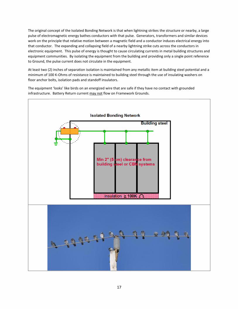
The original concept of the Isolated Bonding Network is that when lightning strikes the structure or nearby, a large
pulse of electromagnetic energy bathes conductors with that pulse. Generators, transformers and similar devices
work on the principle that relative motion between a magnetic field and a conductor induces electrical energy into
that conductor. The expanding and collapsing field of a nearby lightning strike cuts across the conductors in
electronic equipment. This pulse of energy is thought to cause circulating currents in metal building structures and
equipment communities. By isolating the equipment from the building and providing only a single point reference
to Ground, the pulse current does not circulate in the equipment.
At least two (2) inches of separation isolation is maintained from any metallic item at building steel potential and a
minimum of 100 K-Ohms of resistance is maintained to building steel through the use of insulating washers on
floor anchor bolts, isolation pads and standoff insulators.
The equipment ‘looks’ like birds on an energized wire that are safe if they have no contact with grounded
infrastructure. Battery Return current may not flow on Framework Grounds.
18
Figure 31: The Isolated Bonding Network is based on only a single point connection to Ground and isolation from any other paths to building steel downstream of that single point. The concept is similar to birds on a wire.
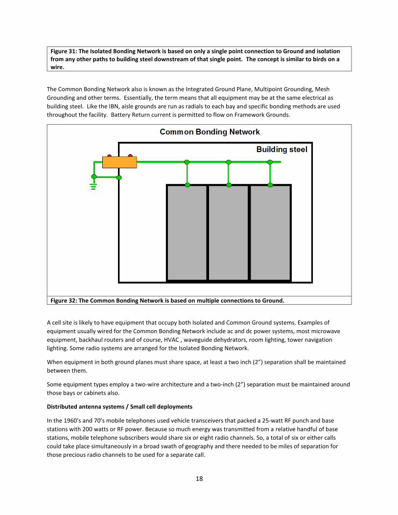
The Common Bonding Network also is known as the Integrated Ground Plane, Multipoint Grounding, Mesh
Grounding and other terms. Essentially, the term means that all equipment may be at the same electrical as
building steel. Like the IBN, aisle grounds are run as radials to each bay and specific bonding methods are used
throughout the facility. Battery Return current is permitted to flow on Framework Grounds.
Figure 32: The Common Bonding Network is based on multiple connections to Ground.
A cell site is likely to have equipment that occupy both Isolated and Common Ground systems. Examples of
equipment usually wired for the Common Bonding Network include ac and dc power systems, most microwave
equipment, backhaul routers and of course, HVAC , waveguide dehydrators, room lighting, tower navigation
lighting. Some radio systems are arranged for the Isolated Bonding Network.
When equipment in both ground planes must share space, at least a two inch (2”) separation shall be maintained
between them.
Some equipment types employ a two-wire architecture and a two-inch (2”) separation must be maintained around
those bays or cabinets also.
Distributed antenna systems / Small cell deployments
In the 1960’s and 70’s mobile telephones used vehicle transceivers that packed a 25-watt RF punch and base
stations with 200 watts or RF power. Because so much energy was transmitted from a relative handful of base
stations, mobile telephone subscribers would share six or eight radio channels. So, a total of six or either calls
could take place simultaneously in a broad swath of geography and there needed to be miles of separation for
those precious radio channels to be used for a separate call.
19
The concept for cellular telephone is that by interconnecting large numbers of base stations that permeate a
geography, low RF power levels could be used and therefore radio channels could be used a relatively short
distance away. Today’s cell phones transmit with less than 100 milliwatts of power and so channels can be reused
even closer. Further, base stations have the capability to ‘tell’ cell phones to reduce power levels when their signal
is strong. doing so increases overall channel capacity and extends available battery time.
The Long-Term Evolution (LTE) plan was designed to bring the cellular network closer to fringe area customers so
that even lower power levels could be used to increase channel availability. Additionally, new frequencies became
available.
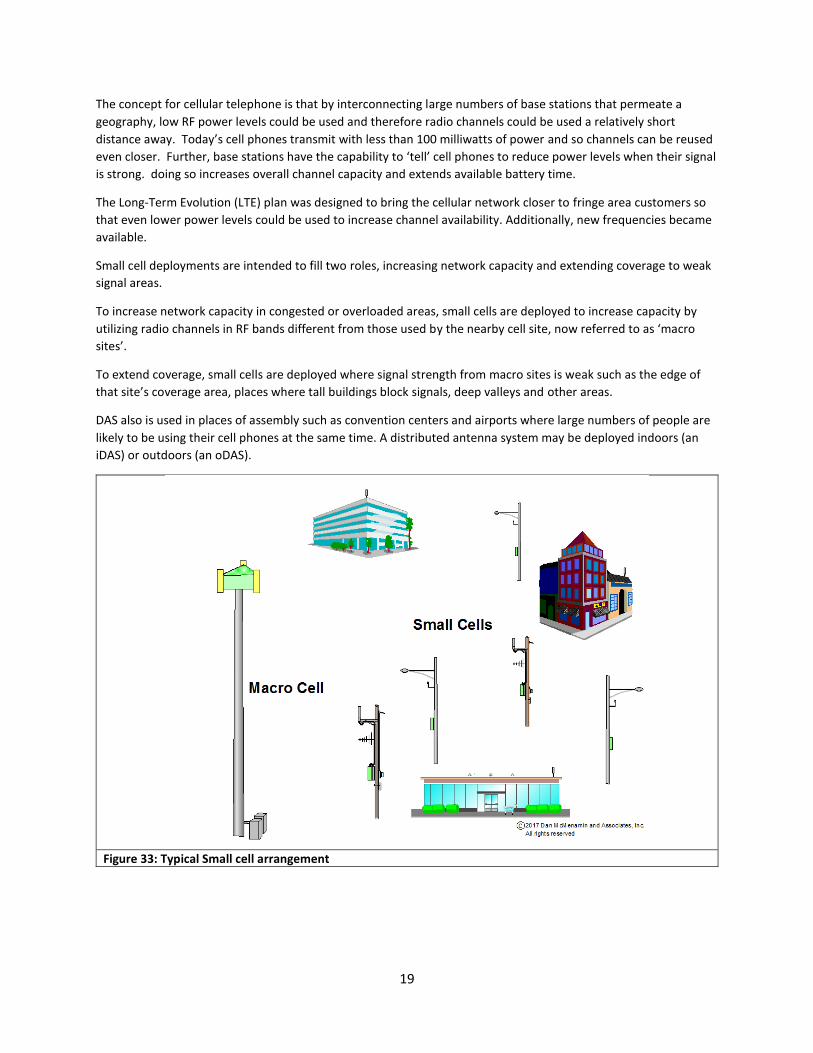
Small cell deployments are intended to fill two roles, increasing network capacity and extending coverage to weak
signal areas.
To increase network capacity in congested or overloaded areas, small cells are deployed to increase capacity by
utilizing radio channels in RF bands different from those used by the nearby cell site, now referred to as ‘macro
sites’.
To extend coverage, small cells are deployed where signal strength from macro sites is weak such as the edge of
that site’s coverage area, places where tall buildings block signals, deep valleys and other areas.
DAS also is used in places of assembly such as convention centers and airports where large numbers of people are
likely to be using their cell phones at the same time. A distributed antenna system may be deployed indoors (an
iDAS) or outdoors (an oDAS).
Figure 33: Typical Small cell arrangement
20
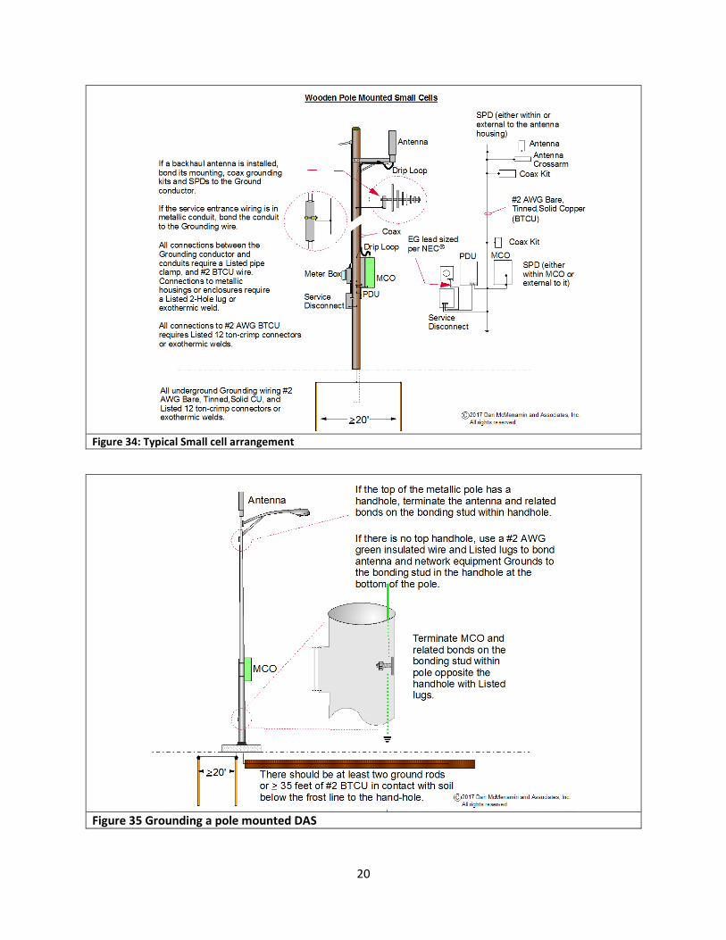
Figure 34: Typical Small cell arrangement
Figure 35 Grounding a pole mounted DAS

21
Figure 36 Grounding a pole mounted DAS
Figure 37 A “stealth” cell
22
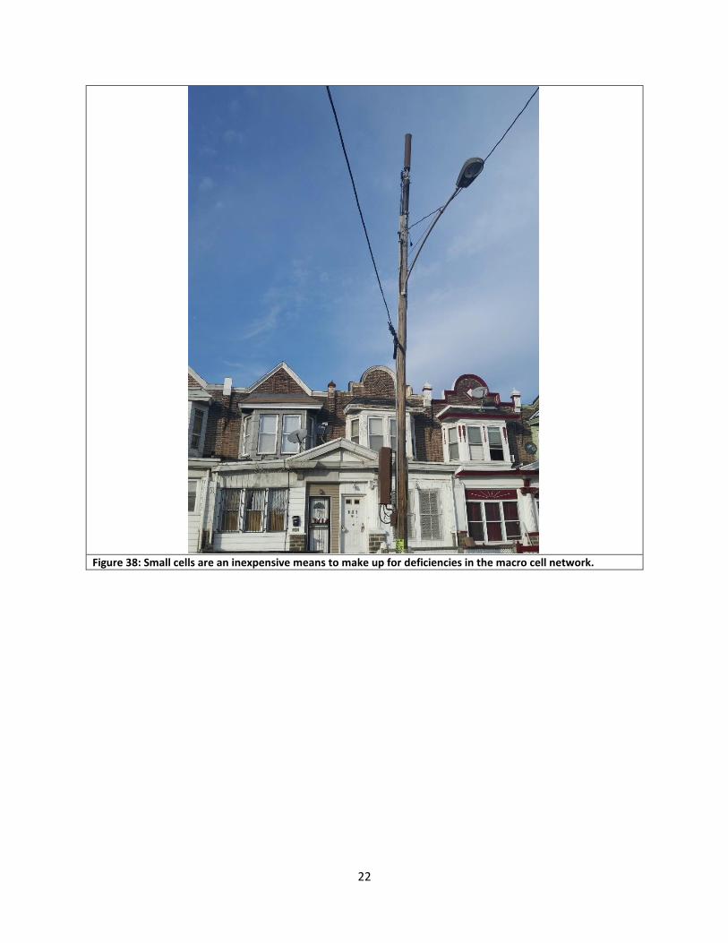
Figure 38: Small cells are an inexpensive means to make up for deficiencies in the macro cell network.

23
Figure 39 : A small cell deployment at a retail store. Note: Only the GPS antenna is visible. The cell antennae are out of view in this photo.

24
Figure: 40 Typical in-building DAS
Summary
Bonding and grounding are all about safety and equipment health & performance.
Avoid confusion: always consult the latest relevant documentation.
i BULLETIN 1728F-U1, REA Specification for Primary Underground Power Cable, James R. Newby, Assistant Administrator Electric Programs, UNITED STATES DEPARTMENT OF AGRICULTURE, USDA Rural Development Utilities Programs ii Ibid, (BULLETIN 1728F-U1, REA) iii NFPA-70, Article 250 et al, The National Electrical Code, National Fire Protection Association, Quincy MA, 2017 Edition iv NFPA 780 Standard for the Installation of Lightning Protection Systems, National Fire Protection Association, Quincy MA, 2017 Edition v UL96A, Standard for Installation Requirements for Lightning Protection Systems, Underwriter’s Laboratories, Inc., 13th Edition vi National Electrical Safety Code (NESC) IEEE C2-2017 8/01/2016 The Institute of Electrical and Electronics Engineers, Inc., New York, NY 10016-5997, USA vii TR-NWT-001075 Generic Requirements for Outside Plant Bonding and Grounding Systems Hardware, Ericsson (formerly Telcordia Technologies, Inc.), Piscataway NJ, Issue 1, August, 1991 viii R56, STANDARDS AND GUIDELINES FOR COMMUNICATION SITES, Motorola Inc., 2005

25
ix GR-295-CORE, Mesh and Isolated Bonding Networks: Definition and Application to Telephone Central Offices, Ericsson (formerly Telcordia Technologies, Inc.), Piscataway NJ, Issue 1, November 2004