layer stackup & smart vias assembly variants serpentine...
TRANSCRIPT
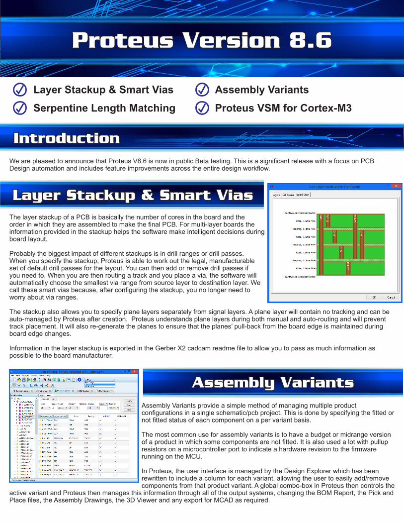
The layer stackup of a PCB is basically the number of cores in the board and the order in which they are assembled to make the final PCB. For multi-layer boards the information provided in the stackup helps the software make intelligent decisions during board layout.
Probably the biggest impact of different stackups is in drill ranges or drill passes. When you specify the stackup, Proteus is able to work out the legal, manufacturable set of default drill passes for the layout. You can then add or remove drill passes if you need to. When you are then routing a track and you place a via, the software will automatically choose the smallest via range from source layer to destination layer. We call these smart vias because, after configuring the stackup, you no longer need to worry about via ranges.
The stackup also allows you to specify plane layers separately from signal layers. A plane layer will contain no tracking and can be auto-managed by Proteus after creation. Proteus understands plane layers during both manual and auto-routing and will prevent track placement. It will also re-generate the planes to ensure that the planes’ pull-back from the board edge is maintained during board edge changes.
Information in the layer stackup is exported in the Gerber X2 cadcam readme file to allow you to pass as much information as possible to the board manufacturer.
Introduction
Layer Stackup & Smart Vias
Proteus Version 8.6
We are pleased to announce that Proteus V8.6 is now in public Beta testing. This is a significant release with a focus on PCB Design automation and includes feature improvements across the entire design workflow.
Layer Stackup & Smart Vias Assembly VariantsSerpentine Length Matching Proteus VSM for Cortex-M3
Assembly VariantsAssembly Variants provide a simple method of managing multiple product configurations in a single schematic/pcb project. This is done by specifying the fitted or not fitted status of each component on a per variant basis.
The most common use for assembly variants is to have a budget or midrange version of a product in which some components are not fitted. It is also used a lot with pullup resistors on a microcontroller port to indicate a hardware revision to the firmware running on the MCU.
In Proteus, the user interface is managed by the Design Explorer which has been rewritten to include a column for each variant, allowing the user to easily add/remove components from that product variant. A global combo-box in Proteus then controls the
active variant and Proteus then manages this information through all of the output systems, changing the BOM Report, the Pick and Place files, the Assembly Drawings, the 3D Viewer and any export for MCAD as required.
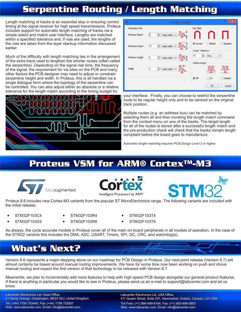
Length matching of tracks is an essential step in ensuring correct timing at the signal receiver for high speed transmissions. Proteus includes support for automatic length matching of tracks via a simple select and match user interface. Lengths are matched within a specified tolerance and, if vias are used, the lengths of the vias are taken from the layer stackup information discussed earlier.
Much of the difficulty with length matching lies in the arrangement of the extra trace used to lengthen the shorter routes (often called the serpentine). Depending on the signal rise time, the frequency of the signal, the requirement for via sites on the PCB and many other factors the PCB designer may need to adjust or constrain serpentine height and width. In Proteus, this is all handled via a single dialogue form where the topology of the serpentine can be controlled. You can also adjust either an absolute or a relative tolerance for the length match according to the timing budget for
your interface. Finally, you can choose to restrict the serpentine route to be regular height only and to be centred on the original track position.
Multiple routes (e.g. an address bus) can be matched by selecting them all and then invoking the length match command from the context menu on one of the tracks. The target length for all of the routes is stored after a successful length match and the pre-production check will check that the tracks remain length compliant before the board goes to manufacture.
Automatic length matching requires PCB Design Level 2 or higher.
Version 8.6 represents a major stepping stone on our roadmap for PCB Design in Proteus. Our next point release (Version 8.7) will almost certainly be based around manual routing improvements. We have for some time now been working on push and shove manual routing and expect the first version of that technology to be released with Version 8.7.
Meanwhile, we plan to incrementally add more features to help with high speed PCB design alongside our general product features.If there is anything in particular you would like to see in Proteus, please send us an e-mail to [email protected] and let us know.
Serpentine Routing / Length Matching
What’s Next?
Labcenter Electronics Ltd. Head Office 21 Hardy Grange, Grassington, BD23 5AJ, United Kingdom. Tel: (+44) 1756 753440, Fax: (+44) 1756 752857 Web: www.labcenter.com, Email: [email protected].
Labcenter Electronics Ltd. USA Office 411 Queen Street, Suite 201, Newmarket, Ontario, Canada, L3Y 2G9 Toll Free: (+1) 866-499-8184, Fax: (+1) 905-898-0683 Web: www.labcenter.com, Email: [email protected]
Proteus VSM for ARM® Cortex™-M3
Proteus 8.6 includes new Cortex-M3 variants from the popular ST MicroElectronics range. The following variants are included with the initial release:
• STM32F103C4 • STM32F103R4 • STM32F103T4
• STM32F103C6 • STM32F103R6 • STM32F103T6
As always, the cycle accurate models in Proteus cover all of the main on-board peripherals in all models of operation. In the case of the STM32 variants this includes the DMA, ADC, USART, Timers, SPI, I2C, CRC, and watchdog(s).