layer 2 attacks and mitigation techniques for the cisco ......... layer 2 attack on the cisco®...
TRANSCRIPT
© 2010 Cisco and/or its affiliates. All rights reserved. This document is Cisco Public Information. Page 1 of 87
White Paper
Layer 2 Attacks and Mitigation Techniques for the Cisco Catalyst 6500
Series
Switches Running Cisco IOS Software
ARP Poisoning (Man-in-the-Middle) Attack and Mitigation Techniques
A CSSTG SE Residency Program White Paper
Jeff King, CCIE 11873, CCSP, CISSP 80875
Kevin Lauerman, CCSP, CISSP 80877
Abstract
Security is at the forefront of most networks, and many companies implement a comprehensive security policy
encompassing many of the OSI layers, from application layer all the way down to IP security. However, one area that
is often left untouched is hardening Layer 2 and this can open the network to a variety of attacks and compromises.
This document will have a focus on understanding and preventing the ARP Poisoning (also known as the Man-In-
The-Middle [MITM]) Layer 2 attack on the Cisco® Catalyst
® 6500 switching series switch running Cisco IOS
®
Software. The Ettercap attack tool will be used to initiate Layer 2 attacks that you might encounter. Mitigation
techniques to stop this attack are also covered.
A MacBook Pro and a Lenovo T61P (laptops) was used for these test and acted as the attacker in some cases and
the victim in others. Both computers also ran VMware.
Note that the attacks performed in this white paper were done in a controlled lab environment. We do not recommend
that you perform this attack on your enterprise network.
Test Equipment
A Cisco Catalyst 6509E switch with a Supervisor 720-3B running Cisco IOS Software 12.2(33)SXI1 in an Advanced
Enterprise Feature Set and a WS-X6748-GE-TX (10/100/1000) Ethernet line card will be used. For the Attacker and
Victim computers, an Apple MacBook Pro and a Lenovo T61P were used.
The MacBook Pro ran a native Mac OS X version 10.5.7 and also had VMware Fusion (2.0.5) with a Ubuntu 9.04 and
a Windows XP SP2 Virtual Machine. The Lenovo T61P ran a Windows XP SP2 host OS and also had VMware with a
Ubuntu 9.04 Virtual Machine. A Linksys USB300M (USB-to-10/100 Ethernet) NIC was used on each machine. By
using this particular NIC, no Bridging or NAT functions were needed in VMware. The Ubuntu 9.04 and Windows XP
Virtual Machines recognize the USB-to-Ethernet NIC, so the Virtual Machines network connection was independent
of the host Operating Systems.
WireShark was used as the packet analyzer in addition to debugs on the Cisco Catalyst 6509E switch to show how
the attack was unleashed and the response/actions of the switch.
ARP (Address Resolution Protocol) Poisoning (MITM) Attack
A Man-In-The-Middle (MITM) attack is achieved when an attacker poisons the ARP cache of two devices with the
(48-bit) MAC address of their Ethernet NIC (Network Interface Card). Once the ARP cache has been successfully

White Paper
© 2010 Cisco and/or its affiliates. All rights reserved. This document is Cisco Public Information. Page 2 of 87
Data SheetW
poisoned, each of the victim devices send all their packets to the attacker when communicating to the other device.
This puts the attacker in the middle of the communications path between the two victim devices; hence the name
Man-In-The-Middle (MITM) attack. It allows an attacker to easily monitor all communication between victim devices.
The objective of this MITM attack is to take over a session. The intent is to intercept and view the information being
passed between the two victim devices.
Three (3) scenarios were used for the MITM attack. They were as follows:
Scenario Description
1 Static IP Address on Attacker machine
2 DHCP from 881 Router (DHCP Server) on Attacker machine
3 DHCP from Cisco Catalyst 6509E DHCP Server on Attacker machine
These (3) scenarios were chosen because they were all valid configurations that one might see in a customer's
network; although scenario 2 and 3 are more likely in an enterprise network.
Scenario 1: Static IP Address on the Attacker Machine
In this scenario, the following hardware/software was used:
Victim 1:
Hardware: Lenovo PC
Software: Windows XP
IP Address: 10.1.0.51/24
MAC Address: 00:1c:25:1a:58:86
NIC: Linksys USB300M (USB-to-Ethernet 10/100)
Cisco Catalyst 6509E Port: GE 1/13
Victim 2:
Hardware: Cisco Catalyst 6509E with a Supervisor 720-3B
Software: Cisco IOS Software 12.2(33)SXI1
IP Address: 10.1.0.1/24 (Interface VLAN 7)
MAC Address: 00:d0:01:39:dc:00
Line Card: WS-X6748-GE-TX (10/100/1000 Ethernet)
Attacker:
Hardware: Apple MacBook Pro
Software: Parent OS is OS X 10.5.7. Running Ubuntu 9.04 OS in VMware Fusion
Attack Tool: Ettercap NG-0.7.3 running in Ubuntu 9.04 OS
IP Address: 10.1.0.60/24 (Static IP)
MAC Address: 00:23:69:48:b8:9c
NIC: Linksys USB300M (USB-to-Ethernet 10/100)
Cisco Catalyst 6509E Port: GE 1/2

White Paper
© 2010 Cisco and/or its affiliates. All rights reserved. This document is Cisco Public Information. Page 3 of 87
Data SheetW
The attacker machine ran the Ubuntu 9.04 operating system inside VMware Fusion. The host was a MacBook Pro
laptop running OS X 10.5.7. A Linksys USB300M (10/100 Ethernet) USB-to-Ethernet NIC was used to connect the
virtual machine (Ubuntu 9.04) to the WS-X6748-GE-TX line card in a Cisco Catalyst 6509E switch with a Supervisor
720-3B running Cisco IOS Software 12.2(33)SXI1. Note that no bridging or NAT (Network Address Translation) was
being used. The host operating systems on the attacker and the victim laptops were not using the Linksys USB300M
NIC, but they were being used exclusively by the Virtual Machines running inside VMware on each laptop. In other
words, no Bridging or NAT was being done between the host Operating System via VMware to the Virtual Machines.
Each Virtual Machine used a dedicated 10/100 Ethernet NIC (USB-to-Ethernet).
Figure 1 shows how everything was connected for the test. Screen shots (snapshots) were taken throughout each
test covered in this white paper. These screen shots help prove that the attacks worked and display the success of
the attack mitigation.
Figure 1. ARP Poisoning (MITM) Attack—Scenario 1
Steps for the MITM (ARP Poisoning) Attack:
1. View initial ARP cache on the Victim PC (Windows XP)
2. View initial ARP cache on the Attacker PC (Ubuntu 9.04)
3. View initial MAC Address-Table on the Cisco Catalyst 6509E (Sup 720-3B)
4. Start Ettercap attack application on the Attacker PC (Ubuntu 9.04)
5. Configure Ettercap for “Unified Sniffing”
6. Select Interface (eth2) to sniff on Ubuntu 9.04 Attacker PC
7. Scan for host on wire
8. List hosts discovered and select targets for attack
9. Start sniffing

White Paper
© 2010 Cisco and/or its affiliates. All rights reserved. This document is Cisco Public Information. Page 4 of 87
Data SheetW
10. Start the MITM (ARP Poisoning) attack
11. Activate the “repoison_arp” plugin in Ettercap
12. Activate the “remote_browser” plugin in Ettercap
13. Open a Telnet session from the Victim to 10.1.0.1 (Int Vlan 7 on 6509E)
14. View “connections” in Ettercap for “active” connections (telnet session)
15. Select “active” session and then “view details”
16. View login and password between Victims (Windows XP and 6509E)
17. Perform “character injection” from Ettercap toward the 6509E (CLI)
18. Perform “character injection” from Ettercap toward Windows XP (Victim)
19. Open up web browser to from Windows XP Victim to CVDM on 6509E
20. Spawn browser on Attacker PC to view Victim's web pages being viewed
21. Scenario 2: DHCP from 881 Router (DHCP Server) on Attacker machine
22. Scenario 3: DHCP from Cisco Catalyst 6509E DHCP Server on Attacker machine
23. Mitigation of the MITM (ARP Poisoning) Attack
24. Summary
Initially, the ARP tables for the victim machine (Windows XP) are reviewed. (See Figure 2.)
Figure 2.
The attacker machine (Ubuntu 9.04) used the eth2 interface. Figure 3 is a snapshot of the network settings.

White Paper
© 2010 Cisco and/or its affiliates. All rights reserved. This document is Cisco Public Information. Page 5 of 87
Data SheetW
Figure 3.
On the Cisco Catalyst 6509E switch, the MAC-Address-Table and the ARP cache is cleared with the commands
shown in Figure 4.
Figure 4.
Figure 5 shows the initial contents of the MAC-Address-Table and ARP cache.
Figure 5.

White Paper
© 2010 Cisco and/or its affiliates. All rights reserved. This document is Cisco Public Information. Page 6 of 87
Data SheetW
From the above listed MAC-Address-Table, IP address 10.1.0.1 is Interface VLAN 7 on the Cisco Catalyst 6509E
switch. IP address 10.1.0.51 is the victim PC running Windows XP, and 10.1.0.60 is the attacker running Ubuntu 9.04
OS (inside VMware Fusion).
On the attacker machine the Ettercap application is started. Please refer to the appendix for details on installing
Ettercap and specific configuration file parameters that need to added or altered. Once Ettercap was started, the
default “Promisc Mode” was verified under the options drop down menu. (See Figure 6.)
Figure 6.
From the “Sniff” drop down menu, “Unified Sniffing” was selected (Figure 7).
Figure 7.
Next the interface that was required to be analyzed was chosen; in this case, it was eth2 on the Ubuntu Attacker
Virtual Machine (Figure 8).

White Paper
© 2010 Cisco and/or its affiliates. All rights reserved. This document is Cisco Public Information. Page 7 of 87
Data SheetW
Figure 8.
A scan for the host on the wire was performed (Figure 9). Note that all of the devices for this paper are in VLAN
Figure 9.
Once the host scan was complete, the host list gathered by Ettercap was viewed (Figure 10).

White Paper
© 2010 Cisco and/or its affiliates. All rights reserved. This document is Cisco Public Information. Page 8 of 87
Data SheetW
Figure 10.
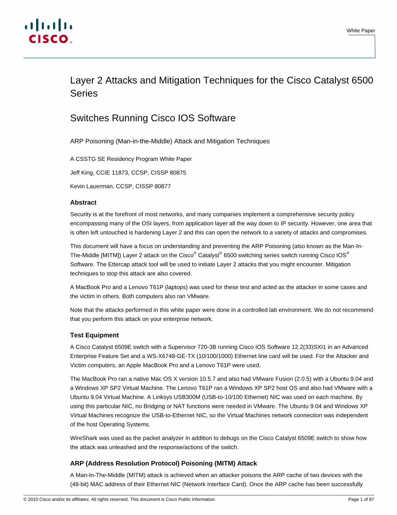
As seen in Figure 11, Ettercap discovered (5) hosts on the LAN.
Figure 11.
For the MITM attack, the Cisco Catalyst 6509E switch had the IP address of 10.1.0.1 (Interface VLAN 7) and the
victim (Windows XP host) had the address 10.1.0.51 with a MAC address of 01:1c:25:1a:58:86. Once the attack was
started, the MAC address of the attacker's NIC showed up on the switch and the victim machine's ARP cache.
Next the targets for the MITM attack were selected. The Cisco Catalyst 6509E (10.1.0.1) was selected as Target 1
and the Windows XP (10.1.0.51) as Target 2 (Figures 12 and 13).

White Paper
© 2010 Cisco and/or its affiliates. All rights reserved. This document is Cisco Public Information. Page 9 of 87
Data SheetW
Figure 12.
White Paper
© 2010 Cisco and/or its affiliates. All rights reserved. This document is Cisco Public Information. Page 10 of 87
Data SheetW
Figure 13.
At this point, sniffing can be started. The “Start” drop down menu is chosen before selecting “Start Sniffing” (Figure
14).

White Paper
© 2010 Cisco and/or its affiliates. All rights reserved. This document is Cisco Public Information. Page 11 of 87
Data SheetW
Figure 14.
In order to start the MITM (ARP Poisoning) Attack, the “MITM” drop down menu item was chosen and “ARP
Poisoning” was selected (Figure 15).
Figure 15.
When asked for optional parameters, the “Sniff Remote Connections” option was selected (Figure 16).

White Paper
© 2010 Cisco and/or its affiliates. All rights reserved. This document is Cisco Public Information. Page 12 of 87
Data SheetW
Figure 16.
Under the “Plugins” drop down menu, two options were selected. Next the “Manage the plugins” option was
selected (Figure 17).
Figure 17.
The parameter named “repoison_arp” was chosen. A “*” beside the parameter was seen when it ran (Figure 18).
Figure 18.
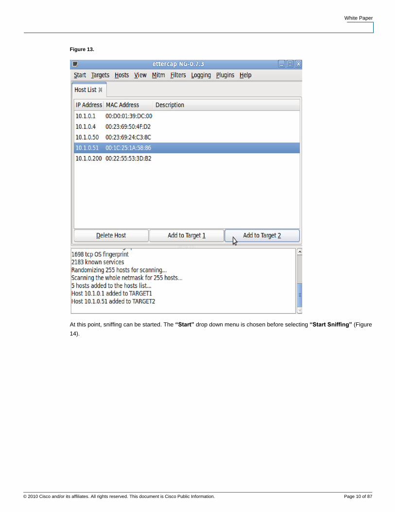
Next the “remote_browser” parameter was chosen. Later when the Victim's HTTP session was sniffed, this
parameter allowed the attacker's web browser to automatically display the web pages the victim is seeing (Figure 19).
White Paper
© 2010 Cisco and/or its affiliates. All rights reserved. This document is Cisco Public Information. Page 13 of 87
Data SheetW
Figure 19.
At the “View” drop down menu, “Connections” was selected. Note that nothing was seen showing up in the window
until the Windows XP host (Victim) opened up a connection to the Cisco Catalyst 6509E switch (Figure 20).
Figure 20.
The Windows XP host (Victim) opened up a Telnet session to 10.1.0.1 (Interface VLAN 7 on the Cisco Catalyst
6509E switch). (See Figure 21.)
Figure 21.
In the snapshot below there were numerous TCP connections on the victim's Windows XP machine. The active
connection with the source IP address of 10.1.0.51 and the destination address of 10.1.0.1 was found to start the
snooping operation (Figure 22).

White Paper
© 2010 Cisco and/or its affiliates. All rights reserved. This document is Cisco Public Information. Page 14 of 87
Data SheetW
Figure 22.
Once this connection was found, a right click on the entry enabled the option to select “view details” (Figure 23).
Figure 23.
Details of the connection were then displayed with information such and TCP, source port, destination port, and so on
(Figure 24).
Figure 24.
White Paper
© 2010 Cisco and/or its affiliates. All rights reserved. This document is Cisco Public Information. Page 15 of 87
Data SheetW
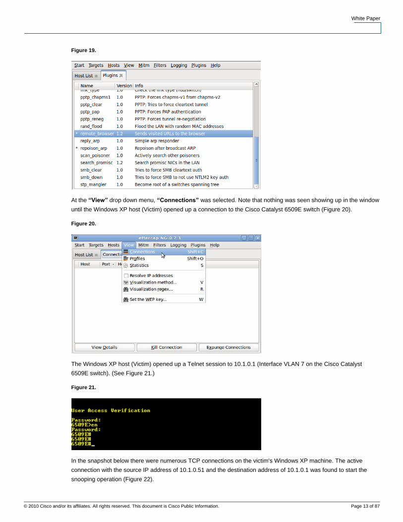
Double clicking on the connection for both sides of the connection resulted in the screen splitting windows. The
Windows XP host (victim) appeared on the left and the CLI window for the Cisco Catalyst 6509E on the right (Figure
25).
Figure 25.
Additionally the option of selecting “join Views” would result in all output being placed in a single window as shown
in Figure 26.
Figure 26.
It can be clearly seen that the victim entered “cisco” as the enable password on the Cisco Catalyst 6509E switch. At
this point, everything can be seen from both victims.
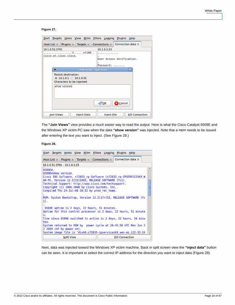
Characters can be injected into either side of the connection. In order to prove this, the Cisco IOS Software command
“show version” was injected toward the Cisco Catalyst 6509E switch. In order to do this, split screen view was
required. while selecting the “Inject Data” button at the bottom of the screen in Figure 27.
White Paper
© 2010 Cisco and/or its affiliates. All rights reserved. This document is Cisco Public Information. Page 16 of 87
Data SheetW
Figure 27.
The “Join Views” view provides a much easier way to read the output. Here is what the Cisco Catalyst 6509E and
the Windows XP victim PC saw when the data “show version” was injected. Note that a <cr> needs to be issued
after entering the text you want to inject. (See Figure 28.)
Figure 28.
Next, data was injected toward the Windows XP victim machine. Back in split screen view the “inject data” button
can be seen. It is important to select the correct IP address for the direction you want to inject data (Figure 29).

White Paper
© 2010 Cisco and/or its affiliates. All rights reserved. This document is Cisco Public Information. Page 17 of 87
Data SheetW
Figure 29.
The screen shot from the victim's Windows XP telnet session window is shown below. At the bottom of the snapshot
is the message that was sent to the victim.
Figure 30.

White Paper
© 2010 Cisco and/or its affiliates. All rights reserved. This document is Cisco Public Information. Page 18 of 87
Data SheetW
On the Ubuntu Virtual Machine (attacker), Wireshark, a free Network Analyzer software package, was running. The
actual ARP poisoning packets being transmitted by Ettercap can be seen on this window as shown in Figure 31.
Figure 31.
Notice that MAC address 00:23:69:48:b8:9c was being advertized as the MAC address for both 10.1.0.51 and
10.1.0.1.
Note that after the successful ARP Poisoning of the switch, the hosts (10.1.0.51 and 10.1.0.61) have the real MAC
Address in the switch’s MAC Address Table as the attacker (10.1.0.60) of 0023.6948.b89c. The “show arp”
command on the switch can be used to display this.
Figure 32.
Using this attack to view a telnet session was easy. Viewing an active HTTP web browser session between the
Windows XP Victim and another Cisco Catalyst switch is also possible. In this case, the victim would open up an http
connection to 172.18.176.153. That happened to be a web connection for CiscoView Device Manager. Note that in
order to do this, the targets in Ettercap should be cleared, and then select Target 1 as 172.18.176.153 and Target 2
as 10.1.0.51.
Figure 33.

White Paper
© 2010 Cisco and/or its affiliates. All rights reserved. This document is Cisco Public Information. Page 19 of 87
Data SheetW
Scenario 2: DHCP from 881 Router (DHCP Server) on Attacker machine
In this attack scenario, the following hardware/software was used:
Victim 1:
Hardware: Lenovo PC
Software: Windows XP
IP Address: 10.1.0.51/24
MAC Address: 00:1c:25:1a:58:86
NIC: Linksys USB300M (USB-to-Ethernet 10/100)
Cisco Catalyst 6509E Port: GE 1/13
Victim 2:
Hardware: Cisco Catalyst 6509E with a Supervisor 720-3B
Software: Cisco IOS Software 12.2(33)SXI1
IP Address: 10.1.0.1/24 (Interface VLAN 7)
MAC Address: 00:d0:01:39:dc:00
Line Card: WS-X6748-GE-TX (10/100/1000 Ethernet)
Attacker:
Hardware: Apple MacBook Pro
Software: Parent OS is OS X 10.5.7. running Windows XP OS in VMware Fusion
Attack Tool: Ettercap NG-0.7.3 (Windows XP)
IP Address: 10.1.0.77/24 (DHCP from DHCP Server on 881 Cisco IOS Software Router)
MAC Address: 00:23:69:50:4f:d2
NIC: Linksys USB300M (USB-to-Ethernet 10/100)
Cisco Catalyst 6509E Port: GE 1/3
White Paper
© 2010 Cisco and/or its affiliates. All rights reserved. This document is Cisco Public Information. Page 20 of 87
Data SheetW
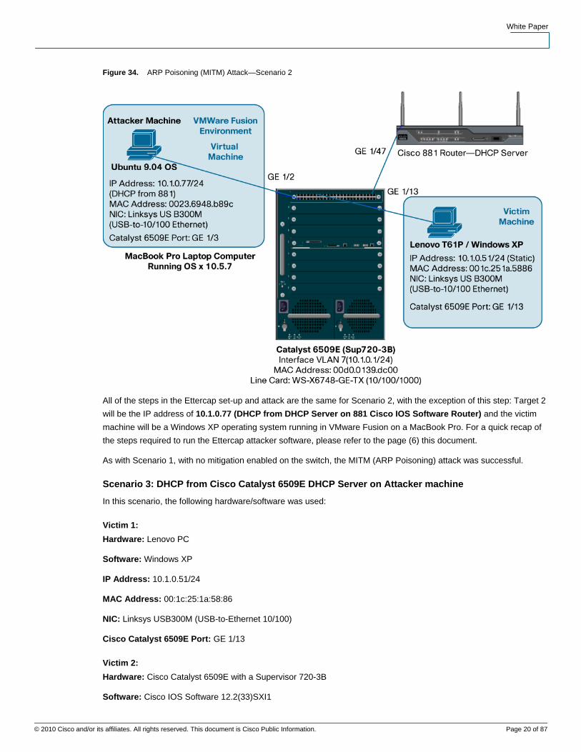
Figure 34. ARP Poisoning (MITM) Attack—Scenario 2
All of the steps in the Ettercap set-up and attack are the same for Scenario 2, with the exception of this step: Target 2
will be the IP address of 10.1.0.77 (DHCP from DHCP Server on 881 Cisco IOS Software Router) and the victim
machine will be a Windows XP operating system running in VMware Fusion on a MacBook Pro. For a quick recap of
the steps required to run the Ettercap attacker software, please refer to the page (6) this document.
As with Scenario 1, with no mitigation enabled on the switch, the MITM (ARP Poisoning) attack was successful.
Scenario 3: DHCP from Cisco Catalyst 6509E DHCP Server on Attacker machine
In this scenario, the following hardware/software was used:
Victim 1:
Hardware: Lenovo PC
Software: Windows XP
IP Address: 10.1.0.51/24
MAC Address: 00:1c:25:1a:58:86
NIC: Linksys USB300M (USB-to-Ethernet 10/100)
Cisco Catalyst 6509E Port: GE 1/13
Victim 2:
Hardware: Cisco Catalyst 6509E with a Supervisor 720-3B
Software: Cisco IOS Software 12.2(33)SXI1

White Paper
© 2010 Cisco and/or its affiliates. All rights reserved. This document is Cisco Public Information. Page 21 of 87
Data SheetW
IP Address: 10.1.0.1/24 (Interface VLAN 7)
MAC Address: 00:d0:01:39:dc:00
Line Card: WS-X6748-GE-TX (10/100/1000 Ethernet)
Attacker:
Hardware: Apple MacBook Pro
Software: Parent OS is OS X 10.5.7. Running Windows XP OS in VMware Fusion
Attack Tool: Ettercap NG-0.7.3 (Windows XP)
IP Address: 10.1.0.88/24 (DHCP from Cisco Catalyst 6509E as DHCP Server)
MAC Address: 00:23:69:50:4f:d2
NIC: Linksys USB300M (USB-to-Ethernet 10/100)
Cisco Catalyst 6509E Port: GE 1/3
Figure 35.
As with Scenario 2, in order not to repeat the same steps, all of the steps in the Ettercap set-up and attack are the
same for Scenario 3 as Scenario 1, with the exception of this step: Target 2 will be the IP address of 10.1.0.88
(DHCP from Cisco Catalyst 6509E acting as the DHCP Server). As with Scenario 2, the victim machine will be a
Windows XP operating system running in VMware Fusion on a MacBook Pro. For a recap of the steps to run the
Ettercap attacker software, please refer to page (6) of this document.
It is no surprise that the results of this scenario were the same as Scenario 1 and Scenario 2. Without any mitigation
enabled on the switch, the MITM (ARP Poisoning) attack was successful.

White Paper
© 2010 Cisco and/or its affiliates. All rights reserved. This document is Cisco Public Information. Page 22 of 87
Data SheetW
Mitigation for the MITM Attack
The primary Cisco IOS Software features on the Cisco Catalyst 6500E (Cisco IOS Software 12.2(33)SXI1) that was
used to mitigate the MITM (ARP Poisoning) attack are DHCP Snooping and Dynamic ARP Inspection (referred to as
DAI throughout this paper). DAI has a dependency on DHCP Snooping. In order to run DAI, DHCP Snooping must be
enabled.
The DHCP Snooping feature is covered in more detail in some of the upcoming DHCP related Layer 2 attacks. DAI is
the focus of this section.
Dynamic ARP Inspection (DAI)
Dynamic ARP Inspection (DAI) is a security feature that is available on Cisco Catalyst 6500 Series switches running
Cisco IOS Software or Cisco Catalyst OS. Dynamic ARP inspection helps prevent ARP poisoning and other ARP-
based attacks by intercepting all ARP (Address Resolution Protocol) requests and responses, and by verifying their
authenticity before updating the switch's local ARP cache or forwarding the packets to the intended destinations. Note
that on Cisco Catalyst 6500 Series switches, Dynamic ARP requires Supervisor 2, Supervisor 32, or Supervisor 720.
As previously stated, a Supervisor 720-3B was used in these tests.
The DAI verification consists primarily of intercepting each ARP packet and comparing its MAC address and IP
address information against the MAC-IP bindings contained in a trusted binding table. DAI discards any ARP packets
that are inconsistent with the information contained in the binding table. The trusted binding table is dynamically
populated by DHCP snooping when this feature is enabled. In addition, DAI allows the configuration of static ARP
ACLs to support systems that use statically configured IP addresses and that do not rely on DHCP.
DAI can also be configured to drop ARP packets with invalid IP addresses, such as 0.0.0.0 or 255.255.255.255, and
ARP packets containing MAC addresses in their payloads that do not match the addresses specified the Ethernet
headers.
Another important feature of DAI is that it implements a configurable rate-limit function that controls the number of
incoming ARP packets (default is 15pps on “untrusted” interfaces). This function is particularly important because all
validation checks are performed by the CPU, and without a rate-limiter, the switch would be much more at risk to
Denial-of-Service (DoS) attacks. When the rate of incoming ARP packets exceeds the configured limit (15pps
default), the switch places the port in an “error-disabled” state.
The port remains in this state until you intervene. You can use the “errdisable recovery” global command on the
switch to enable error disable recovery so that the ports will automatically emerge from the “error-disabled” state
after a specified timeout period.
Figure 36 shows the format of the command and the available parameters:

White Paper
© 2010 Cisco and/or its affiliates. All rights reserved. This document is Cisco Public Information. Page 23 of 87
Data SheetW
Figure 36.
Note that there is an interface command (“ip arp inspection limit”) that can be used to disable the default ARP rate-
limiting without having to fully disable DAI on the switch. We will be showing this command later.
Similarly to DHCP snooping, DAI associates a trust state with each interface on the system. Packets arriving on
trusted interfaces bypass all DAI validation checks, while those arriving on untrusted interfaces go through the DAI
validation process. In a typical network configuration for DAI, all ports connected to host ports are configured as
untrusted, while all ports connected to switches are configured as trusted. With this configuration, all ARP packets
entering the network from a given switch will have passed the security check. By default, DAI is disabled on all
VLANs, and all ports are configured as untrusted.
As previously mentioned, DAI populates its database of valid MAC address to IP address bindings through DHCP
snooping. It also validates ARP packets against statically configured ARP ACLs. It is important to note that ARP
ACLs have precedence over entries in the DHCP snooping database. ARP packets are first compared to user-
configured ARP ACLs. If the ARP ACL denies the ARP packet, then the packet will be denied even if a valid binding
exists in the database populated by DHCP snooping.
DAI can be configured to drop ARP packets containing MAC addresses in the body of the ARP packet that do not
match the addresses specified in the Ethernet headers. The difference is that in Cisco IOS Software the MAC
address validation can be done based on source and destination MAC addresses:
● Source MAC addresses: DAI checks the source MAC address in the Ethernet header against the sender
MAC address in the ARP body. This check is performed on both ARP requests and responses. When
enabled, packets with different MAC addresses are classified as invalid and are dropped.
● Destination MAC addresses: DAI checks the destination MAC address in the Ethernet header against the
target MAC address in ARP body. This check is performed for ARP responses. When enabled, packets with
different MAC addresses are classified as invalid and are dropped.
Similarly to Cisco Catalyst OS, in Cisco IOS Software, DAI can be configured to drop ARP packets with invalid and
unexpected IP addresses. Addresses include 0.0.0.0, 255.255.255.255, and all IP multicast addresses. Sender IP
addresses are checked in all ARP requests and responses, and target IP addresses are checked only in ARP
responses.
Another difference between Cisco Catalyst OS and Cisco IOS Software is that in the later ARP inspection rate limiting
is implemented per interface only, and not globally. The default threshold is also different, in Cisco IOS Software the
rate for untrusted interfaces is by default set to 15pps.

White Paper
© 2010 Cisco and/or its affiliates. All rights reserved. This document is Cisco Public Information. Page 24 of 87
Data SheetW
Enabling MITM Mitigation and Results
The mitigation of the MITM (ARP Poisoning) attack is the same for each the (3) scenarios presented thus far. Since in
most cases in an enterprise network the DHCP server will be external to the Cisco Catalyst switch, we will be using
scenario 2 in the screen shots and CLI commands (scenario 2 – DHCP address to attacker with Cisco 881 Router
acting as the DHCP Server).
The mitigation process begins by logging into the Cisco Catalyst 6509E switch and configuring DHCP Snooping
(prerequisite for Dynamic ARP Inspection [DAI]). Below is screen shot of the configuration parameters needed to
enable these features.
Enabling DHCP Snooping
Figure 37.
Enabling Dynamic ARP Inspection (DAI)
Figure 38.
As mentioned earlier in the section describing how DAI works, by default, DAI turns on ARP rate-limited to 15pps on
untrusted ports. The only trusted ported that were configured was GE 1/47, which was the access switch port
connected to the 881 Router (DHCP Server). Figure 39 shows the commands used on the trusted port.
Figure 39.
In order to be able to scan for a host using Ettercap (with DHCP Snooping and DAI enabled on the switch), ARP
Rate-Limiting (default is 15pps) was disabled on the attacker's switch port. If this is not done then the switch will put
port GE 1/3 into an error-disabled state. The attacker was connected to GE 1/3.

White Paper
© 2010 Cisco and/or its affiliates. All rights reserved. This document is Cisco Public Information. Page 25 of 87
Data SheetW
Figure 40.
Here are the full interface configurations for the “trusted port” connecting to the DHCP Server (881 Router), victim
machine, and attacker machine.
Figure 41. External DHCP Server (881 Router) connection
Figure 42. Victim Machine (Lenovo Windows XP @ 10.1.0.51/24)
Figure 43. Attacker Machine (Ubuntu running inside VMware Fusion on MacBook Pro @ 10.1.0.77 [DHCP])
Running the MITM (ARP Poisoning) Attack with Mitigation Enabled on the Switch
To see the full list of steps to perform this attack, please refer back to page (6) of this document. Keep in mind that
scenario 2 was used for the attack, so the attacker was a Windows XP Virtual Machine (running VMware Fusion on
MacBook Pro laptop) and the victim was the Lenovo host running Windows XP (10.1.0.51/24), who is connected to
port GE 1/13 on the 6509E. The attacker machine gained a DHCP address (10.1.0.77/24 in this case) from an
external DHCP Server; which was the 881 Router connected to port GE 1/47 on the Cisco Catalyst 6509E switch.
The attacker (Windows XP host) was connected to port GE 1/3 on the switch.

White Paper
© 2010 Cisco and/or its affiliates. All rights reserved. This document is Cisco Public Information. Page 26 of 87
Data SheetW
Figure 44. Attacker getting a DHCP address from the external DHCP Server (881 Router)
Note that the victim machine (10.1.0.51) had a static IP address that was excluded from the DHCP Server IP pool of
available addresses. Below is the DHCP Server portion of the configuration on the 881 Router that was acting as the
external DHCP server.
Figure 45.
Due to this setup and because DHCP Snooping and Dynamic ARP Inspection (DAI) was enabled on the Cisco
Catalyst 6509E switch, the following commands (global configuration) were required.
Figure 46.
Without the static bindings for 10.1.0.51, the attacker would not be able to reach the victim and the following
messages from the Cisco Catalyst 6509E switch would be seen:

White Paper
© 2010 Cisco and/or its affiliates. All rights reserved. This document is Cisco Public Information. Page 27 of 87
Data SheetW
Figure 47.
This would not be necessary if the victim machine got an IP address from the DHCP Server.
In order for the attacker machine to be able to ping any host (with DHCP Snooping and DAI enabled in the switch),
the attacker's IP address and MAC address must be in the DHCP Snooping Bindings Table. For this attacker, the
address is in the table.
Figure 48.
The Attacker could successfully ping their default gateway and the intended victim machine.
Figure 49.
In this example output, all the static and DHCP Snooping bindings on the Cisco Catalyst 6509E switch are seen. Note
that the static IP Source Bindings were added in an earlier step.

White Paper
© 2010 Cisco and/or its affiliates. All rights reserved. This document is Cisco Public Information. Page 28 of 87
Data SheetW
Figure 50.
Without any additional parameters added, an output from the “sho ip dhcp snooping” command is shown. Recall
that that GE 1/47 is connected to the external DHCP Server (881 Router) and this port was configured as a “trusted”
port.
Figure 51.
Figure 52. Ettercap on the Attacker (Windows XP Host)

White Paper
© 2010 Cisco and/or its affiliates. All rights reserved. This document is Cisco Public Information. Page 29 of 87
Data SheetW
The Ettercap attacking steps have been compressed into just a few snapshots. The snapshot of Ettercap above
running on the Windows XP host attacker shows that (4) hosts found during the host scan and those host are listed.
Address 10.1.0.1 (Interface VLAN 7 on 6509E) and 10.1.0.51 (Victim) were selected as targets.
Before the attack from Ettercap was launched, the following debugs were enabled on the Cisco Catalyst 6509E
switch.
Figure 53.
Select the MITM (ARP Poisoning) Attack, and enable the associated plugin to commence sniffing. Note that when
running Ettercap on a Windows XP host, the plugin to re-poison ARP is not listed; whereas it is a valid and open
when running Ettercap from within Ubuntu 9.04 (Linux host).
Figure 54.
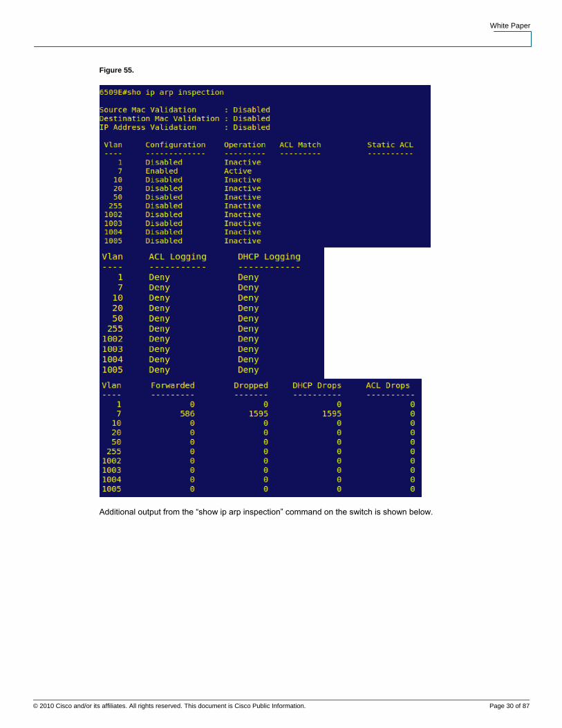
It can be seen that no connections exist from within Ettercap for the two targets. The output from the Cisco Catalyst
6509E regarding the ARP Inspection is shown in Figure 55.
White Paper
© 2010 Cisco and/or its affiliates. All rights reserved. This document is Cisco Public Information. Page 30 of 87
Data SheetW
Figure 55.
Additional output from the “show ip arp inspection” command on the switch is shown below.

White Paper
© 2010 Cisco and/or its affiliates. All rights reserved. This document is Cisco Public Information. Page 31 of 87
Data SheetW
Figure 56.
The debug output from the Cisco Catalyst 6509E switch that was logged when the Ettercap MITM attack took place is
shown below. Both DHCP Snooping and IP ARP Inspection debugs were enabled along with logging buffered.
Figure 57.
White Paper
© 2010 Cisco and/or its affiliates. All rights reserved. This document is Cisco Public Information. Page 32 of 87
Data SheetW
Summary
ARP (Address Resolution Protocol) Poisoning, A.K.A. Man-In-The-Middle (MITM), is a very effective attack if proper
mitigation techniques have not been implemented. As the MITM attack requires the attacker to be on the same
network as the intended victims, an attack would need to be initiated from the inside of the network. With the Ettercap
tool being publicly available, and versions that run on both Windows and Linux based operating systems, most
network could be susceptible to this attack if mitigation techniques were not in place.
By using the DHCP Snooping and Dynamic ARP Inspection (DAI) features, multiple types of Layer 2 attacks,
including the ARP Poisoning (MITM) attack can be stopped.
DHCP Snooping is a security feature capable of intercepting DHCP messages crossing a switch and blocking bogus
DHCP offers. DHCP Snooping uses the concept of trusted and untrusted ports. Typically, the trusted ports are used
to reach DHCP servers or relay agents, while untrusted ports are used to connect to clients. All DHCP messages are
allowed on trusted ports, while only DHCP client messages are accepted on untrusted ports. As neither servers nor
relay agents are supposed to connect to untrusted ports, server messages like DHCPOFFER, DHCPACK, and
DHCPNAK are dropped on untrusted ports. In addition, DHCP Snooping builds and maintains a MAC-to-IP binding
table that is used to validate DHCP packets received from untrusted ports. DHCP Snooping discards all untrusted
DHCP packets not consistent with the information in the binding table. For DHCP snooping to function properly, all
DHCP servers must be connected to the switch through trusted interfaces. The DHCP Snooping binding table
contains the MAC address, IP address, lease time in seconds, and VLAN port information for the DHCP clients on the
untrusted ports of a switch. The information that is contained in a DHCP-snooping binding table is removed from the
binding table when its lease expires or DHCP Snooping is disabled in the VLAN.
Dynamic ARP Inspection (DAI) is a security feature that helps prevent ARP poisoning and other ARP-based attacks
by intercepting all ARP requests and responses, and by verifying their authenticity before updating the switch's local
ARP cache or forwarding the packets to the intended destinations. The DAI verification consists primarily of
intercepting each ARP packet and comparing its MAC address and IP address information against the MAC-IP
bindings contained in a trusted binding table. DAI discards any ARP packets that are inconsistent with the information
contained in the binding table. The trusted binding table is dynamically populated by DHCP snooping when this
feature is enabled. In addition, DAI allows the configuration of static ARP ACLs to support systems that use statically
configured IP addresses and that do not rely on DHCP. DAI can also be configured to drop ARP packets with invalid
IP addresses, such as 0.0.0.0 or 255.255.255.255, and ARP packets containing MAC addresses in their payloads
that do not match the addresses specified the Ethernet headers.
Another important feature of DAI is that it implements a configurable rate-limit function that controls the number of
incoming ARP packets. This function is particularly important because all validation checks are performed by the
CPU, and without a rate-limiter, there could be a DoS condition.
DAI associates a trust state with each interface on the system, similar to DHCP Snooping. Packets arriving on trusted
interfaces bypass all DAI validation checks, while those arriving on untrusted interfaces go through the DAI validation
process. In a typical network configuration for DAI, all ports connected to host ports are configured as untrusted,
while all ports connected to switches are configured as trusted. With this configuration, all ARP packets entering the
network from a given switch will have passed the security check. By default, DAI is disabled on all VLANs, and all
ports are configured as untrusted.
As discussed earlier, DAI populates its database of valid MAC address to IP address bindings through DHCP
snooping. It also validates ARP packets against statically configured ARP ACLs. It is important to note that ARP
ACLs have precedence over entries in the DHCP snooping database. ARP packets are first compared to user-
configured ARP ACLs. If the ARP ACL denies the ARP packet, then the packet will be denied even if a valid binding
exists in the database populated by DHCP snooping.
White Paper
© 2010 Cisco and/or its affiliates. All rights reserved. This document is Cisco Public Information. Page 33 of 87
Data SheetW
Note that configuring DHCP Snooping is a prerequisite to configure Dynamic ARP Inspection (DAI). It is also worth
noting that if you plan to use any static IP addresses are planned to be used when configuring DHCP Snooping and
DAI, a static IP-to-MAC address mapping must also be entered in your Cisco Catalyst 6500 switches configuration.
For instance, lets say that we want to assign a static IP-to-MAC mapping for the IP address 10.1.0.60 with the MAC
address of 0023.6948.B89C for interface GE1/2 on VLAN 7 is required. The global configuration command on switch
would be:
ip source binding 0023.6948.B89C vlan 7 10.1.0.60 interface Gi1/2
References
Solder, Carl (2006). “Cisco Networkers.”
Cisco Systems, Inc. (2007). “Infrastructure Protection on Cisco Catalyst 6500 and 4500 Series Switches.”
Cisco Systems, Inc. (2009). “Configuring DHCP Snooping”
Cisco Systems, Inc. (2009). “Configuring Dynamic ARP Inspection.”
Cisco Systems, Inc. (2009). “Design Zone for Security.”
Hodgdon, Scott (2009). “CSSTG SE Residency Project Plan.”
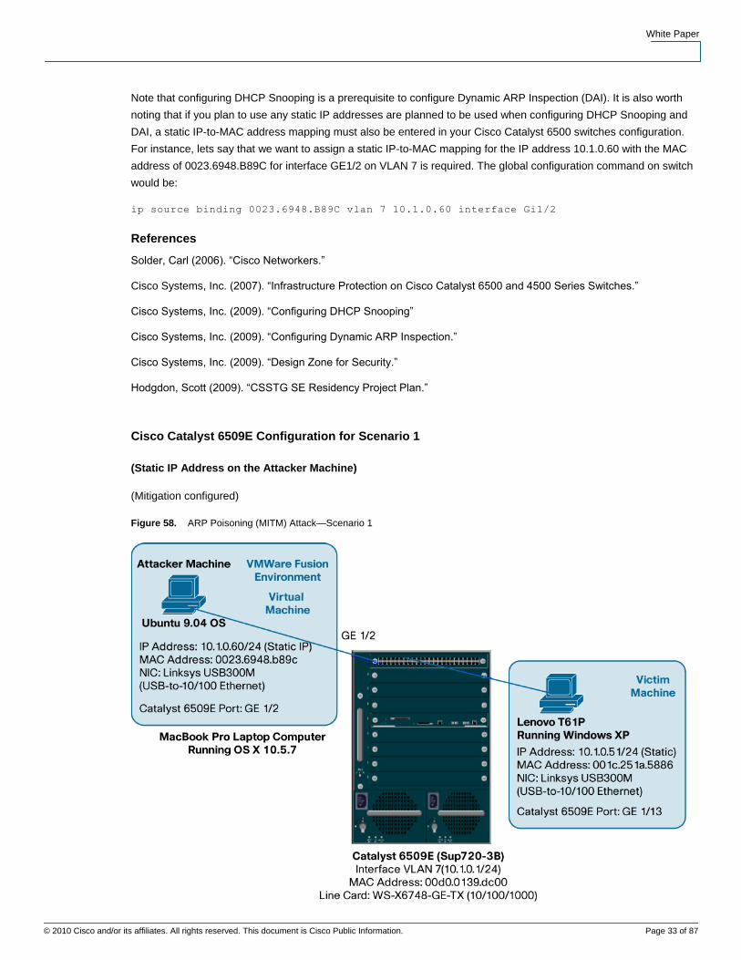
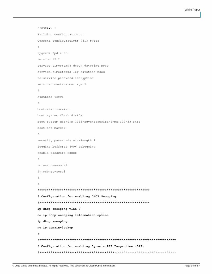
Cisco Catalyst 6509E Configuration for Scenario 1
(Static IP Address on the Attacker Machine)
(Mitigation configured)
Figure 58. ARP Poisoning (MITM) Attack—Scenario 1
White Paper
© 2010 Cisco and/or its affiliates. All rights reserved. This document is Cisco Public Information. Page 34 of 87
Data SheetW
6509E#wr t
Building configuration...
Current configuration: 7513 bytes
!
upgrade fpd auto
version 12.2
service timestamps debug datetime msec
service timestamps log datetime msec
no service password-encryption
service counters max age 5
!
hostname 6509E
!
boot-start-marker
boot system flash disk0:
boot system disk0:s72033-adventerprisek9-mz.122-33.SXI1
boot-end-marker
!
security passwords min-length 1
logging buffered 4096 debugging
enable password xxxxx
!
no aaa new-model
ip subnet-zero!
!
!
!***********************************************************
! Configuration for enabling DHCP Snooping
!***********************************************************
ip dhcp snooping vlan 7
no ip dhcp snooping information option
ip dhcp snooping
no ip domain-lookup
!
!*************************************************************************
! Configuration for enabling Dynamic ARP Inspection (DAI)
!*************************************************************************

White Paper
© 2010 Cisco and/or its affiliates. All rights reserved. This document is Cisco Public Information. Page 35 of 87
Data SheetW
ip arp inspection vlan 7
ip arp inspection log-buffer entries 1024
ip arp inspection log-buffer logs 1024 interval 10
!*************************************************************************************
! Because we are using a Static IP Address in Scenario 1, we must configure
! a source binding since we have enabled DHCP Snooping and Dynamic
! ARP Inspection (DAI). This will bind the MAC address on the NIC on the
! Attacker Machine to the static IP address connected to port GE1/2 on vlan 7
!*************************************************************************************
ip source binding 0023.6948.B89C vlan 7 10.1.0.60 interface Gi1/2
!
vtp domain CISCO
vtp mode transparent
mls netflow interface
no mls flow ip
mls cef error action reset
!
redundancy
!
keepalive-enable
mode sso
main-cpu
auto-sync running-config
spanning-tree mode pvst
!
!
!*************************************************************************************
! The “errdisable recovery cause all” command will automatically add the following
configuration
! commands to the switch
!*************************************************************************************
errdisable recovery cause udld
errdisable recovery cause bpduguard
errdisable recovery cause security-violation
errdisable recovery cause channel-misconfig
errdisable recovery cause pagp-flap
errdisable recovery cause dtp-flap
errdisable recovery cause link-flap

White Paper
© 2010 Cisco and/or its affiliates. All rights reserved. This document is Cisco Public Information. Page 36 of 87
Data SheetW
errdisable recovery cause gbic-invalid
errdisable recovery cause l2ptguard
errdisable recovery cause psecure-violation
errdisable recovery cause dhcp-rate-limit
errdisable recovery cause mac-limit
errdisable recovery cause unicast-flood
errdisable recovery cause vmps
errdisable recovery cause storm-control
errdisable recovery cause arp-inspection
errdisable recovery cause link-monitor-failure
errdisable recovery cause oam-remote-failure
errdisable recovery cause loopback
errdisable recovery interval 30
fabric timer 15
!
vlan internal allocation policy ascending
vlan access-log ratelimit 2000
!
vlan 7,10,20
!
vlan 50
remote-span
!
vlan 255
!
!
interface GigabitEthernet1/1
switchport
switchport access vlan 7
switchport mode access
shutdown
!
!
!
!*************************************************************************************
************
! GE1/2 Connected to “Attacker” Ubuntu 9.04 Virtual Machine running on the
! MacBook Pro inside VMware Fusion. In Scenario 1, the Ubuntu 9.04 Attacker
White Paper
© 2010 Cisco and/or its affiliates. All rights reserved. This document is Cisco Public Information. Page 37 of 87
Data SheetW
! machine will have an IP address of 10.1.0.60/24.
!*************************************************************************************
interface GigabitEthernet1/2
switchport
switchport access vlan 7
switchport mode access
!
!
**************************************************************************************
! Configure DHCP Snooping ARP Rate Limiting on Attacker's switch port
!*************************************************************************************
ip dhcp snooping limit rate 10
!
!*************************************************************************************
! In order to be able to run a host scan using the Ettercap application on the
! Attacker PC (connected to GE1/3), we have to turn off the default ARP
! Rate-Limit of 15pps. The following command will do this. In a production
! environment, you would not want to use this command!.
!*************************************************************************************
ip arp inspection limit none
!
!
interface GigabitEthernet1/3
switchport
switchport access vlan 7
switchport mode access
shutdown
!
interface GigabitEthernet1/4
no ip address
shutdown
!
interface GigabitEthernet1/5
no ip address
shutdown
!
interface GigabitEthernet1/6
no ip address
White Paper
© 2010 Cisco and/or its affiliates. All rights reserved. This document is Cisco Public Information. Page 38 of 87
Data SheetW
shutdown
!
interface GigabitEthernet1/7
no ip address
shutdown
!
!
!
interface GigabitEthernet1/8
no ip address
shutdown
!
interface GigabitEthernet1/9
no ip address
shutdown
!
interface GigabitEthernet1/10
no ip address
shutdown
!
interface GigabitEthernet1/11
no ip address
shutdown
!
interface GigabitEthernet1/12
no ip address
shutdown
!
!*************************************************************************************
! GE1/13 is connected to Victim 1, the Lenovo PC running Windows XP.
! It has an IP address of 10.1.0.51/24.
!*************************************************************************************
interface GigabitEthernet1/13
switchport
switchport access vlan 7
switchport mode access
!

White Paper
© 2010 Cisco and/or its affiliates. All rights reserved. This document is Cisco Public Information. Page 39 of 87
Data SheetW
interface GigabitEthernet1/14
switchport
switchport access vlan 7
switchport mode access
shutdown
!
interface GigabitEthernet1/15
switchport
shutdown
!
interface GigabitEthernet1/16
no ip address
shutdown
!
interface GigabitEthernet1/17
no ip address
shutdown
!
!
!
interface GigabitEthernet1/18
no ip address
shutdown
!
interface GigabitEthernet1/19
no ip address
shutdown
!
interface GigabitEthernet1/20
no ip address
shutdown
!
interface GigabitEthernet1/21
no ip address
shutdown
!
interface GigabitEthernet1/22
White Paper
© 2010 Cisco and/or its affiliates. All rights reserved. This document is Cisco Public Information. Page 40 of 87
Data SheetW
no ip address
shutdown
!
interface GigabitEthernet1/23
no ip address
shutdown
!
interface GigabitEthernet1/24
no ip address
shutdown
!
interface GigabitEthernet1/25
no ip address
shutdown
!
interface GigabitEthernet1/26
no ip address
shutdown
!
interface GigabitEthernet1/27
no ip address
shutdown
!
interface GigabitEthernet1/28
no ip address
shutdown
!
!
!
!
!
interface GigabitEthernet1/29
no ip address
shutdown
!
interface GigabitEthernet1/30
no ip address
White Paper
© 2010 Cisco and/or its affiliates. All rights reserved. This document is Cisco Public Information. Page 41 of 87
Data SheetW
shutdown
!
interface GigabitEthernet1/31
no ip address
shutdown
!
interface GigabitEthernet1/32
no ip address
shutdown
!
interface GigabitEthernet1/33
no ip address
shutdown
!
interface GigabitEthernet1/34
no ip address
shutdown
!
interface GigabitEthernet1/35
no ip address
shutdown
!
interface GigabitEthernet1/36
no ip address
shutdown
!
interface GigabitEthernet1/37
no ip address
shutdown
!
interface GigabitEthernet1/38
no ip address
shutdown
!
interface GigabitEthernet1/39
no ip address
shutdown

White Paper
© 2010 Cisco and/or its affiliates. All rights reserved. This document is Cisco Public Information. Page 42 of 87
Data SheetW
!
interface GigabitEthernet1/40
no ip address
shutdown
!
interface GigabitEthernet1/41
no ip address
shutdown
!
interface GigabitEthernet1/42
no ip address
shutdown
!
interface GigabitEthernet1/43
no ip address
shutdown
!
interface GigabitEthernet1/44
no ip address
shutdown
!
interface GigabitEthernet1/45
no ip address
shutdown
!
interface GigabitEthernet1/46
switchport
switchport access vlan 7
switchport mode access
!
interface GigabitEthernet1/47
description *** Connects to 881 Router Acting as DHCP Server [10.1.0.200] port 0/5,
used in scenario 2 ***
switchport
switchport access vlan 7
switchport mode access
ip arp inspection trust
ip dhcp snooping trust
White Paper
© 2010 Cisco and/or its affiliates. All rights reserved. This document is Cisco Public Information. Page 43 of 87
Data SheetW
shutdown
!
interface GigabitEthernet1/48
switchport
switchport mode dynamic auto
!
interface GigabitEthernet5/1
no ip address
shutdown
!
interface GigabitEthernet5/2
no ip address
shutdown
!
interface Vlan1
no ip address
shutdown
!
interface Vlan7
ip address 10.1.0.1 255.255.255.0
!
router eigrp 100
network 10.1.0.0 0.0.0.255
network 172.18.176.0 0.0.0.255
no auto-summary
!
ip classless
!
no ip http server
no ip http secure-server
!
control-plane
!
dial-peer cor custom
!
alias exec sdsb show ip dhcp snooping binding
!
White Paper
© 2010 Cisco and/or its affiliates. All rights reserved. This document is Cisco Public Information. Page 44 of 87
Data SheetW
line con 0
exec-timeout 0 0
line vty 0 4
session-timeout 800
password 12345
login
length 0
transport preferred none
transport input all
transport output none
line vty 5 15
login
transport input lat pad udptn telnet rlogin ssh
!
scheduler process-watchdog terminate
scheduler switch allocate 1000 1000
scheduler allocate 400 100
mac-address-table aging-time 480
!
end

White Paper
© 2010 Cisco and/or its affiliates. All rights reserved. This document is Cisco Public Information. Page 45 of 87
Data SheetW
Cisco Catalyst 6509E Configuration for Scenario 2
(Cisco 881 Router acting as external DHCP Server)
(Mitigation configured)
Figure 59. ARP Poisoning (MITM) Attack—Scenario 2
6509E#wr t
Building configuration...
Current configuration: 7513 bytes
!
upgrade fpd auto
version 12.2
service timestamps debug datetime msec
service timestamps log datetime msec
no service password-encryption
service counters max age 5
!
hostname 6509E
!
boot-start-marker

White Paper
© 2010 Cisco and/or its affiliates. All rights reserved. This document is Cisco Public Information. Page 46 of 87
Data SheetW
boot system flash disk0:
boot system disk0:s72033-adventerprisek9-mz.122-33.SXI1
boot-end-marker
!
security passwords min-length 1
logging buffered 4096 debugging
enable password 12345
!
no aaa new-model
ip subnet-zero
!
!***********************************************************
! Configuration for enabling DHCP Snooping
!***********************************************************
ip dhcp snooping vlan 7
no ip dhcp snooping information option
ip dhcp snooping
no ip domain-lookup
!
!*************************************************************************
! Configuration for enabling Dynamic ARP Inspection (DAI)
!*************************************************************************
ip arp inspection vlan 7
ip arp inspection log-buffer entries 1024
ip arp inspection log-buffer logs 1024 interval 10
vtp domain CISCO
vtp mode transparent
mls netflow interface
no mls flow ip
mls cef error action reset
!
redundancy
keepalive-enable
mode sso
main-cpu
auto-sync running-config
spanning-tree mode pvst

White Paper
© 2010 Cisco and/or its affiliates. All rights reserved. This document is Cisco Public Information. Page 47 of 87
Data SheetW
!
!
!
!
!*************************************************************************************
! The “errdisable recovery cause all” command will automatically add the following
configuration
! commands to the switch
!*************************************************************************************
errdisable recovery cause udld
errdisable recovery cause bpduguard
errdisable recovery cause security-violation
errdisable recovery cause channel-misconfig
errdisable recovery cause pagp-flap
errdisable recovery cause dtp-flap
errdisable recovery cause link-flap
errdisable recovery cause gbic-invalid
errdisable recovery cause l2ptguard
errdisable recovery cause psecure-violation
errdisable recovery cause dhcp-rate-limit
errdisable recovery cause mac-limit
errdisable recovery cause unicast-flood
errdisable recovery cause vmps
errdisable recovery cause storm-control
errdisable recovery cause arp-inspection
errdisable recovery cause link-monitor-failure
errdisable recovery cause oam-remote-failure
errdisable recovery cause loopback
errdisable recovery interval 30
fabric timer 15
!
vlan internal allocation policy ascending
vlan access-log ratelimit 2000
!
vlan 7,10,20
!
vlan 50
remote-span

White Paper
© 2010 Cisco and/or its affiliates. All rights reserved. This document is Cisco Public Information. Page 48 of 87
Data SheetW
!
vlan 255
!
interface GigabitEthernet1/1
switchport
switchport access vlan 7
switchport mode access
shutdown
!
interface GigabitEthernet1/2
switchport
switchport access vlan 7
switchport mode access
shutdown
!
!*************************************************************************************
! GE1/3 Connected to “Attacker” Windows XP Virtual Machine running on the
! MacBook Pro inside VMware Fusion.
!*************************************************************************************
interface GigabitEthernet1/3
switchport
switchport access vlan 7
switchport mode access
!
**************************************************************************************
! Configure DHCP Snooping ARP Rate Limiting on Attacker's switch port
!*************************************************************************************
ip dhcp snooping limit rate 10
!
!*************************************************************************************
! In order to be able to run a host scan using the Ettercap application on the
! Attacker PC (connected to GE1/3), we have to turn off the default ARP
! Rate-Limit of 15pps. The following command will do this. In a production
! environment, you would not want to use this command!.
!*************************************************************************************
ip arp inspection limit none
!
!

White Paper
© 2010 Cisco and/or its affiliates. All rights reserved. This document is Cisco Public Information. Page 49 of 87
Data SheetW
interface GigabitEthernet1/4
no ip address
shutdown
!
interface GigabitEthernet1/5
no ip address
shutdown
!
interface GigabitEthernet1/6
no ip address
shutdown
!
interface GigabitEthernet1/7
no ip address
shutdown
!
interface GigabitEthernet1/8
no ip address
shutdown
!
interface GigabitEthernet1/9
no ip address
shutdown
!
interface GigabitEthernet1/10
no ip address
shutdown
!
interface GigabitEthernet1/11
no ip address
shutdown
!
interface GigabitEthernet1/12
no ip address
shutdown
!

White Paper
© 2010 Cisco and/or its affiliates. All rights reserved. This document is Cisco Public Information. Page 50 of 87
Data SheetW
!*************************************************************************************
! GE1/13 is connected to Victim 1, the Lenovo PC running Windows XP.
! It has an IP address of 10.1.0.51/24.
!*************************************************************************************
interface GigabitEthernet1/13
switchport
switchport access vlan 7
switchport mode access
!
interface GigabitEthernet1/14
switchport
switchport access vlan 7
switchport mode access
shutdown
!
interface GigabitEthernet1/15
switchport
shutdown
!
interface GigabitEthernet1/16
no ip address
shutdown
!
interface GigabitEthernet1/17
no ip address
shutdown
!
interface GigabitEthernet1/18
no ip address
shutdown
!
interface GigabitEthernet1/19
no ip address
shutdown
!
interface GigabitEthernet1/20
no ip address

White Paper
© 2010 Cisco and/or its affiliates. All rights reserved. This document is Cisco Public Information. Page 51 of 87
Data SheetW
shutdown
!
interface GigabitEthernet1/21
no ip address
shutdown
!
interface GigabitEthernet1/22
no ip address
shutdown
!
interface GigabitEthernet1/23
no ip address
shutdown
!
interface GigabitEthernet1/24
no ip address
shutdown
!
interface GigabitEthernet1/25
no ip address
shutdown
!
interface GigabitEthernet1/26
no ip address
shutdown
!
interface GigabitEthernet1/27
no ip address
shutdown
!
interface GigabitEthernet1/28
no ip address
shutdown
!
interface GigabitEthernet1/29
no ip address
shutdown

White Paper
© 2010 Cisco and/or its affiliates. All rights reserved. This document is Cisco Public Information. Page 52 of 87
Data SheetW
!
interface GigabitEthernet1/30
no ip address
shutdown
!
interface GigabitEthernet1/31
no ip address
shutdown
!
interface GigabitEthernet1/32
no ip address
shutdown
!
interface GigabitEthernet1/33
no ip address
shutdown
!
interface GigabitEthernet1/34
no ip address
shutdown
!
interface GigabitEthernet1/35
no ip address
shutdown
!
interface GigabitEthernet1/36
no ip address
shutdown
!
interface GigabitEthernet1/37
no ip address
shutdown
!
interface GigabitEthernet1/38
no ip address
shutdown
!

White Paper
© 2010 Cisco and/or its affiliates. All rights reserved. This document is Cisco Public Information. Page 53 of 87
Data SheetW
interface GigabitEthernet1/39
no ip address
shutdown
!
interface GigabitEthernet1/40
no ip address
shutdown
!
interface GigabitEthernet1/41
no ip address
shutdown
!
interface GigabitEthernet1/42
no ip address
shutdown
!
interface GigabitEthernet1/43
no ip address
shutdown
!
interface GigabitEthernet1/44
no ip address
shutdown
!
interface GigabitEthernet1/45
no ip address
shutdown
!
interface GigabitEthernet1/46
switchport
switchport access vlan 7
switchport mode access
shutdown
!

White Paper
© 2010 Cisco and/or its affiliates. All rights reserved. This document is Cisco Public Information. Page 54 of 87
Data SheetW
**************************************************************************************
! GE1/47 connects to the Cisco 881 Router (port 0/5) that is acting as the external
! DHCP Server for scenario 2.
!*************************************************************************************
interface GigabitEthernet1/47
description *** Connects to 881 Router Acting as DHCP Server [10.1.0.200] port 0/5
***
switchport
switchport access vlan 7
switchport mode access
!*************************************************************************************
! Configuring GE1/47 as a trusted port for both DHCP Snooping and Dynamic ARP
! Inspection (DAI)
!*************************************************************************************
ip arp inspection trust
ip dhcp snooping trust
!
interface GigabitEthernet1/48
switchport
switchport mode dynamic auto
!
interface GigabitEthernet5/1
no ip address
shutdown
!
interface GigabitEthernet5/2
no ip address
shutdown
!
interface Vlan1
no ip address
shutdown
!
interface Vlan7
ip address 10.1.0.1 255.255.255.0
!
router eigrp 100
network 10.1.0.0 0.0.0.255

White Paper
© 2010 Cisco and/or its affiliates. All rights reserved. This document is Cisco Public Information. Page 55 of 87
Data SheetW
network 172.18.176.0 0.0.0.255
no auto-summary
!
ip classless
!
no ip http server
no ip http secure-server
!
control-plane
!
dial-peer cor custom
!
alias exec sdsb show ip dhcp snooping binding
!
line con 0
exec-timeout 0 0
line vty 0 4
session-timeout 800
password 12345
login
length 0
transport preferred none
transport input all
transport output none
line vty 5 15
login
transport input lat pad udptn telnet rlogin ssh
!
scheduler process-watchdog terminate
scheduler switch allocate 1000 1000
scheduler allocate 400 100
mac-address-table aging-time 480
!
end

White Paper
© 2010 Cisco and/or its affiliates. All rights reserved. This document is Cisco Public Information. Page 56 of 87
Data SheetW
Cisco Catalyst 6509E Configuration for Scenario 3
(Cisco Catalyst 6509E switch acting as the internal DHCP Server)
(Mitigation configured)
Figure 60. ARP Poisoning (MITM) Attack—Scenario 3
6509E#wr t
Building configuration...
Current configuration: 7513 bytes
!
upgrade fpd auto
version 12.2
service timestamps debug datetime msec
service timestamps log datetime msec
no service password-encryption
service counters max age 5
!
hostname 6509E
!
boot-start-marker
boot system flash disk0:

White Paper
© 2010 Cisco and/or its affiliates. All rights reserved. This document is Cisco Public Information. Page 57 of 87
Data SheetW
boot system disk0:s72033-adventerprisek9-mz.122-33.SXI1
boot-end-marker
!
security passwords min-length 1
logging buffered 4096 debugging
enable password xxxxx
!
no aaa new-model
ip subnet-zero!
!
!*************************************************************************************
! Cisco Catalyst 6509E being used as a DHCP Server. IP Pool defined. Test machines
that use
! static IP addresses in the same subnet as the DHCP Server have been excluded from
the
! DHCP IP Pool of addresses.
!*************************************************************************************
ip dhcp excluded-address 10.1.0.1 10.1.0.2
ip dhcp excluded-address 10.1.0.50 10.1.0.61
!
ip dhcp pool SE_Residency
network 10.1.0.0 255.255.255.0
domain-name SE_Residency.com
dns-server 10.1.0.1
default-router 10.1.0.1
lease 5
!
!***********************************************************
! Configuration for enabling DHCP Snooping
!***********************************************************
ip dhcp snooping vlan 7
no ip dhcp snooping information option
ip dhcp snooping
no ip domain-lookup
!
!*************************************************************************
! Configuration for enabling Dynamic ARP Inspection (DAI)
!*************************************************************************

White Paper
© 2010 Cisco and/or its affiliates. All rights reserved. This document is Cisco Public Information. Page 58 of 87
Data SheetW
ip arp inspection vlan 7
ip arp inspection log-buffer entries 1024
ip arp inspection log-buffer logs 1024 interval 10
vtp domain CISCO
vtp mode transparent
mls netflow interface
no mls flow ip
mls cef error action reset
!
redundancy
keepalive-enable
mode sso
main-cpu
auto-sync running-config
spanning-tree mode pvst
!
!*************************************************************************************
! The “errdisable recovery cause all” command will automatically add the following
configuration
! commands to the switch
!*************************************************************************************
errdisable recovery cause udld
errdisable recovery cause bpduguard
errdisable recovery cause security-violation
errdisable recovery cause channel-misconfig
errdisable recovery cause pagp-flap
errdisable recovery cause dtp-flap
errdisable recovery cause link-flap
errdisable recovery cause gbic-invalid
errdisable recovery cause l2ptguard
errdisable recovery cause psecure-violation
errdisable recovery cause dhcp-rate-limit
errdisable recovery cause mac-limit
errdisable recovery cause unicast-flood
errdisable recovery cause vmps
errdisable recovery cause storm-control
errdisable recovery cause arp-inspection
errdisable recovery cause link-monitor-failure
White Paper
© 2010 Cisco and/or its affiliates. All rights reserved. This document is Cisco Public Information. Page 59 of 87
Data SheetW
errdisable recovery cause oam-remote-failure
errdisable recovery cause loopback
errdisable recovery interval 30
fabric timer 15
!
vlan internal allocation policy ascending
vlan access-log ratelimit 2000
!
vlan 7,10,20
!
vlan 50
remote-span
!
vlan 255
!
!
interface GigabitEthernet1/1
switchport
switchport access vlan 7
switchport mode access
shutdown
!
interface GigabitEthernet1/2
switchport
switchport access vlan 7
switchport mode access
shutdown
!
!*************************************************************************************
! GE1/3 Connected to “Attacker” Windows XP Virtual Machine running on the
! MacBook Pro inside VMware Fusion. Getting IP Address 10.1.0.88/24 from
! the DHCP Server (Cisco Catalyst 6509E acting as DHCP Server).
!*************************************************************************************
interface GigabitEthernet1/3
switchport
switchport access vlan 7
switchport mode access
White Paper
© 2010 Cisco and/or its affiliates. All rights reserved. This document is Cisco Public Information. Page 60 of 87
Data SheetW
!
**************************************************************************************
! Configure DHCP Snooping ARP Rate Limiting on Attacker's switch port
!*************************************************************************************
ip dhcp snooping limit rate 10
!
!*************************************************************************************
! In order to be able to run a host scan using the Ettercap application on the
! Attacker PC (connected to GE1/3), we have to turn off the default ARP
! Rate-Limit of 15pps. The following command will do this. In a production
! environment, you would not want to use this command!.
!*************************************************************************************
ip arp inspection limit none
!
interface GigabitEthernet1/4
no ip address
shutdown
!
interface GigabitEthernet1/5
no ip address
shutdown
!
interface GigabitEthernet1/6
no ip address
shutdown
!
interface GigabitEthernet1/7
no ip address
shutdown
!
interface GigabitEthernet1/8
no ip address
shutdown
!
interface GigabitEthernet1/9
no ip address
shutdown
!

White Paper
© 2010 Cisco and/or its affiliates. All rights reserved. This document is Cisco Public Information. Page 61 of 87
Data SheetW
interface GigabitEthernet1/10
no ip address
shutdown
!
interface GigabitEthernet1/11
no ip address
shutdown
!
interface GigabitEthernet1/12
no ip address
shutdown
!
!*************************************************************************************
! GE1/13 connected to “Victim 1” Lenovo PC running Windows XP. It uses IP
! Address 10.1.0.51/24.
!*************************************************************************************
interface GigabitEthernet1/13
switchport
switchport access vlan 7
switchport mode access
!
interface GigabitEthernet1/14
switchport
switchport access vlan 7
switchport mode access
shutdown
!
interface GigabitEthernet1/15
switchport
shutdown
!
interface GigabitEthernet1/16
no ip address
shutdown
!
interface GigabitEthernet1/17
no ip address

White Paper
© 2010 Cisco and/or its affiliates. All rights reserved. This document is Cisco Public Information. Page 62 of 87
Data SheetW
shutdown
!
!
interface GigabitEthernet1/18
no ip address
shutdown
!
interface GigabitEthernet1/19
no ip address
shutdown
!
interface GigabitEthernet1/20
no ip address
shutdown
!
interface GigabitEthernet1/21
no ip address
shutdown
!
interface GigabitEthernet1/22
no ip address
shutdown
!
interface GigabitEthernet1/23
no ip address
shutdown
!
interface GigabitEthernet1/24
no ip address
shutdown
!
interface GigabitEthernet1/25
no ip address
shutdown
!
interface GigabitEthernet1/26
no ip address
White Paper
© 2010 Cisco and/or its affiliates. All rights reserved. This document is Cisco Public Information. Page 63 of 87
Data SheetW
shutdown
!
interface GigabitEthernet1/27
no ip address
shutdown
!
interface GigabitEthernet1/28
no ip address
shutdown
!
interface GigabitEthernet1/29
no ip address
shutdown
!
interface GigabitEthernet1/30
no ip address
shutdown
!
interface GigabitEthernet1/31
no ip address
shutdown
!
interface GigabitEthernet1/32
no ip address
shutdown
!
interface GigabitEthernet1/33
no ip address
shutdown
!
interface GigabitEthernet1/34
no ip address
shutdown
!
interface GigabitEthernet1/35
no ip address
shutdown

White Paper
© 2010 Cisco and/or its affiliates. All rights reserved. This document is Cisco Public Information. Page 64 of 87
Data SheetW
!
interface GigabitEthernet1/36
no ip address
shutdown
!
interface GigabitEthernet1/37
no ip address
shutdown
!
interface GigabitEthernet1/38
no ip address
shutdown
!
interface GigabitEthernet1/39
no ip address
shutdown
!
interface GigabitEthernet1/40
no ip address
shutdown
!
interface GigabitEthernet1/41
no ip address
shutdown
!
!
interface GigabitEthernet1/42
no ip address
shutdown
!
interface GigabitEthernet1/43
no ip address
shutdown
!
interface GigabitEthernet1/44
no ip address
shutdown

White Paper
© 2010 Cisco and/or its affiliates. All rights reserved. This document is Cisco Public Information. Page 65 of 87
Data SheetW
!
interface GigabitEthernet1/45
no ip address
shutdown
!
interface GigabitEthernet1/46
switchport
switchport access vlan 7
switchport mode access
!
interface GigabitEthernet1/47
description *** Connects to 881 Router Acting as DHCP Server [10.1.0.200] port 0/5,
used in scenario 2 ***
switchport
switchport access vlan 7
switchport mode access
ip arp inspection trust
ip dhcp snooping trust
shutdown
!
interface GigabitEthernet1/48
switchport
switchport mode dynamic auto
!
interface GigabitEthernet5/1
no ip address
shutdown
!
interface GigabitEthernet5/2
no ip address
shutdown
!
interface Vlan1
no ip address
shutdown
!
!
!

White Paper
© 2010 Cisco and/or its affiliates. All rights reserved. This document is Cisco Public Information. Page 66 of 87
Data SheetW
interface Vlan7
ip address 10.1.0.1 255.255.255.0
!
!
!
router eigrp 100
network 10.1.0.0 0.0.0.255
network 172.18.176.0 0.0.0.255
no auto-summary
!
ip classless
!
no ip http server
no ip http secure-server
!
control-plane
!
dial-peer cor custom
!
alias exec sdsb show ip dhcp snooping binding
!
line con 0
exec-timeout 0 0
line vty 0 4
session-timeout 800
password 12345
login
length 0
transport preferred none
transport input all
transport output none
line vty 5 15
login
transport input lat pad udptn telnet rlogin ssh
!
scheduler process-watchdog terminate
scheduler switch allocate 1000 1000
White Paper
© 2010 Cisco and/or its affiliates. All rights reserved. This document is Cisco Public Information. Page 67 of 87
Data SheetW
scheduler allocate 400 100
mac-address-table aging-time 480
!
end
Appendix ........................................................................................................................................................ 68
Introduction to Ubuntu Install Guide for L2 Attack Tools ................................................................................ 68
Ettercap ......................................................................................................................................... 68
Ettercap Installation via Synaptic Package Manager ..................................................................................... 68
Modification of Ettercap initialization file “/etc/etter.conf” ............................................................................... 73
Launching Ettercap ........................................................................................................................................ 77
Yersinia ......................................................................................................................................... 79
Yersinia Installation via Synaptic Package Manager ..................................................................................... 79
Launching Yersinia’s Graphical Interface ....................................................................................................... 79
Launching Yersinia’s Interactive Interface ..................................................................................................... 81
packETH ........................................................................................................................................ 83
packETH Installation via Synaptic Package Manager .................................................................................... 83
Launching packETH ...................................................................................................................................... 84
Wireshark ...................................................................................................................................... 85
Wireshark Installation via Synaptic Package Manager .................................................................................. 85
Launching Wireshark ..................................................................................................................................... 86

White Paper
© 2010 Cisco and/or its affiliates. All rights reserved. This document is Cisco Public Information. Page 68 of 87
Data SheetW
Appendix
Introduction to Ubuntu Install Guide for L2 Attack Tools
This appendix is intended for those users that are not familiar with the Ubuntu Linux OS and want to be able to
quickly download and use the Layer 2 attack and monitoring tools (Ettercap, Yersinia, packETH and Wireshark)
that are utilized throughout these series of Layer 2 attack whitepapers. The Synaptic Package Manager in Ubuntu is
the GUI application for installing software packages in the dpkg format with the file extensions of “.deb.” This dpkg
format was the first Linux packaging to integrate dependency information. The Debian Package Mgmt. system
database tracks which software packages are installed, which version is installed, and other packages that it is
dependent on. This allows you to automatically identify, download, and install all dependent applications that are part
of your original application installation selection. The Synaptic Package Manager by default will only point to those
dpkg repositories that are supported by Ubuntu Linux. If you want the Synaptic Package Manager to point to
repositories that are not supported by Ubuntu, you must add those repositories to /etc/apt/sources.list.
This appendix covers the complete installation of the Ettercap application, modification of its initial configuration file
(parameter values that provide privilege level, rerouting capabilities, remote browser capabilities, etc to ettercap) and
where and how to launch the application. The other L2 attack and monitoring tool installations (Yersinia, packETH
and Wireshark) are not covered in their entirety as the process is similar. These applications do differ in where and
how they are launched and the appendix will cover these unique differences in detail.
Listed below is a summary of the different attack scenario’s and which L2 attack tools were used:
STP MiTM (Vlan) Attack—Yersinia, Ettercap, Wireshark
STP MiTM (ISL) Attack—Yersinia, Ettercap, packETH, Wireshark
ARP MiTM Attack—Ettercap, Wireshark
MAC Overflow Attack—Ettercap, Wireshark
DHCP Consumption Attack—Yersinia, Wireshark
Ettercap
Ettercap Installation via Synaptic Package Manager
Select “System>Administration>Synaptic Package Manager” to load Synaptic; the GUI application to download,
install and remove applications on Ubuntu Linux. (See Figure 61.)

White Paper
© 2010 Cisco and/or its affiliates. All rights reserved. This document is Cisco Public Information. Page 69 of 87
Data SheetW
Figure 61.
You will be required to enter your password to perform Administrative Tasks such as installing software (Figure 62).
Figure 62.
Type “ettercap” in the Quick Search Field and the Synaptic Package Manager will locate the application for
installation (Figure 63).
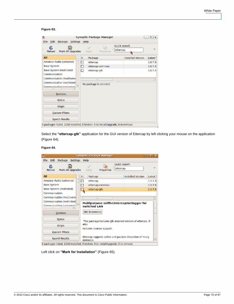
White Paper
© 2010 Cisco and/or its affiliates. All rights reserved. This document is Cisco Public Information. Page 70 of 87
Data SheetW
Figure 63.
Select the “ettercap-gtk” application for the GUI version of Ettercap by left clicking your mouse on the application
(Figure 64).
Figure 64.
Left click on “Mark for Installation” (Figure 65).

White Paper
© 2010 Cisco and/or its affiliates. All rights reserved. This document is Cisco Public Information. Page 71 of 87
Data SheetW
Figure 65.
Additional application dependencies have been identified. Mark this additional application for installation (Figure 66).
Figure 66.
Ettercap has been marked along with its application dependency on “ettercap-common.” Go ahead and hit “Apply”
to install both applications (Figure 67).

White Paper
© 2010 Cisco and/or its affiliates. All rights reserved. This document is Cisco Public Information. Page 72 of 87
Data SheetW
Figure 67.
Hit “Apply” in the summary screen to confirm your installation selections (Figure 68).
Figure 68.

White Paper
© 2010 Cisco and/or its affiliates. All rights reserved. This document is Cisco Public Information. Page 73 of 87
Data SheetW
When your installation is complete, the “Changes applied” window will pop up. Close this window to proceed
(Figure 69).
Figure 69.
Synaptic will indicate that the applications have been successfully installed by the filled green boxes next to the
application (Figure 70).
Figure 70.
Modification of Ettercap initialization file “/etc/etter.conf”
We are going to use the terminal shell to modify the “/etc/etter.conf” file. Select
“Applications>Accessories>Terminal “ to open a terminal window (Figure 71).

White Paper
© 2010 Cisco and/or its affiliates. All rights reserved. This document is Cisco Public Information. Page 74 of 87
Data SheetW
Figure 71.
When the terminal window opens, type “sudo gedit /etc/etter.conf” to open the file with the appropriate privileges to
modify the file. You will be prompted for the root password to continue (Figure 72).
Figure 72.

White Paper
© 2010 Cisco and/or its affiliates. All rights reserved. This document is Cisco Public Information. Page 75 of 87
Data SheetW
The “ec_uid” and “ec_gid” values both need to be changed to “0” to provide the appropriate privilege level to
Ettercap upon execution. The default values are “65534.” Change these to “0” as depicted in Figure 73.
Figure 73.
The “port_steal_send_delay” value needs to be changed to “1” microseconds. The default value is “2000”
microseconds for the port steal send delay. We need to populate arp tables faster than Cisco’s default ARP table
timeout values can clear them. (See Figure 74.)
Figure 74.

White Paper
© 2010 Cisco and/or its affiliates. All rights reserved. This document is Cisco Public Information. Page 76 of 87
Data SheetW
Comment out “#” the original remote browser command line and add the remote_browser command line as entered
below—mozilla is replaced with firefox. This fixes the MiTM remote browsing plugin within ettercap. This enables
us to view the same web pages as a victim in real time (Figure 75).
Figure 75.
Uncomment the iptables commands by removing the “#” symbol. This will allow you to reroute traffic when performing
a MiTM attack on behalf of the gateway and the victim (Figure 76).
Figure 76.

White Paper
© 2010 Cisco and/or its affiliates. All rights reserved. This document is Cisco Public Information. Page 77 of 87
Data SheetW
When you have completed these modifications, hit the “save” tab at the top of the editor (Figure 77).
Figure 77.
Launching Ettercap
Ettercap can be launched from “Applications>System Tools” or you can right click on “ettercap” from “System
Tools” and install a launcher to the desktop (Figure 78).
Figure 78.

White Paper
© 2010 Cisco and/or its affiliates. All rights reserved. This document is Cisco Public Information. Page 78 of 87
Data SheetW
Ettercap can now be launched from the Ubuntu Desktop (Figure 79).
Figure 79.
Double clicking on the Ettercap icon launches the following Ettercap application (Figure 80).
Figure 80.
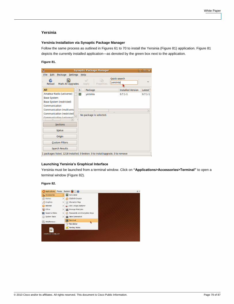
White Paper
© 2010 Cisco and/or its affiliates. All rights reserved. This document is Cisco Public Information. Page 79 of 87
Data SheetW
Yersinia
Yersinia Installation via Synaptic Package Manager
Follow the same process as outlined in Figures 61 to 70 to install the Yersinia (Figure 81) application. Figure 81
depicts the currently installed application—as denoted by the green box next to the application.
Figure 81.
Launching Yersinia’s Graphical Interface
Yersinia must be launched from a terminal window. Click on “Applications>Accessories>Terminal” to open a
terminal window (Figure 82).
Figure 82.

White Paper
© 2010 Cisco and/or its affiliates. All rights reserved. This document is Cisco Public Information. Page 80 of 87
Data SheetW
Give the terminal window root privilege by typing the command “sudo su” at the command prompt. You will be
required to provide a root password. There are several different options to launch yersinia from the CLI—“-G “ for
Graphical or “-I” for interactive. The “yersinia–G” option loads the Graphical version of Yersinia depicted in Figure
83.
Figure 83.
The default Yersinia screen when using the Graphical option for launching the application (Figure 84).
Figure 84.

White Paper
© 2010 Cisco and/or its affiliates. All rights reserved. This document is Cisco Public Information. Page 81 of 87
Data SheetW
Launching Yersinia’s Interactive Interface
To launch the Interactive interface of Yersinia, you must be using a full size terminal window. Make sure you
maximize your terminal session before launching the application with the “-I” option (Figure 85).
Figure 85.
Once the window is maximized launch Yersinia with the “-I” option from the CLI (Figure 86).
Figure 86.
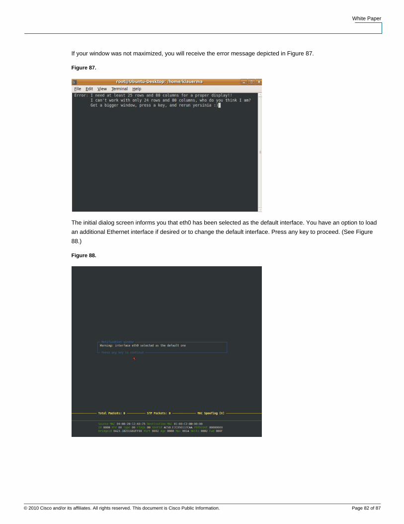
White Paper
© 2010 Cisco and/or its affiliates. All rights reserved. This document is Cisco Public Information. Page 82 of 87
Data SheetW
If your window was not maximized, you will receive the error message depicted in Figure 87.
Figure 87.
The initial dialog screen informs you that eth0 has been selected as the default interface. You have an option to load
an additional Ethernet interface if desired or to change the default interface. Press any key to proceed. (See Figure
88.)
Figure 88.

White Paper
© 2010 Cisco and/or its affiliates. All rights reserved. This document is Cisco Public Information. Page 83 of 87
Data SheetW
Type a lower case “h” to pull up the help screen of available commands. This is just another interface for using
Yersinia. Our examples of L2 attacks all use the Graphical version of Yersinia. This should be enough to get you
going if you choose to use the Interactive interface to Yersinia (Figure 89).
Figure 89.
packETH
packETH Installation via Synaptic Package Manager
Follow the same process as outlined in Figures 58 to 67 to install the packETH (Figure 90) application. Figure 90
depicts the currently installed application—as denoted by the green box next to the application.

White Paper
© 2010 Cisco and/or its affiliates. All rights reserved. This document is Cisco Public Information. Page 84 of 87
Data SheetW
Figure 90.
Launching packETH
packETH must be launched from a terminal window. Click on “Applications>Accessories>Terminal“ to open a
terminal window (Figure 91).
Figure 91.

White Paper
© 2010 Cisco and/or its affiliates. All rights reserved. This document is Cisco Public Information. Page 85 of 87
Data SheetW
Give the terminal window root privilege by typing the command “sudo su” at the command prompt. You will be
required to provide a root password. Once you have root privilege, type “packeth” at the command prompt and hit
enter (Figure 92).
Figure 92.
This is a partial view of the default window that appears for packETH upon launching. You will notice that this
packet generator supports ver II, 802.3 and 802.1q frames. (See Figure 93.)
Figure 93.
Wireshark
Wireshark Installation via Synaptic Package Manager
Follow the same process as outlined in Figures 58 to 67 to install the Wireshark (Figure 94) application. Figure 94
depicts the currently installed application—as denoted by the green box next to the application. You will note that the
Wireshark application is dependent on “wireshark-common.” The Synaptic Package Manager will identify the
dependency and prompt you to also install “wireshark-common.” (See Figure 94.)

White Paper
© 2010 Cisco and/or its affiliates. All rights reserved. This document is Cisco Public Information. Page 86 of 87
Data SheetW
Figure 94.
Launching Wireshark
Wireshark can be launched from “Applications>Internet>Wireshark (as root)” by a single click or you can add the
launcher to the desktop by right clicking on wireshark and then select “Add this launcher to desktop.” The
Wireshark icon can be double clicked from the Desktop to launch the application. Launched application is depicted in
Figures 95 and 96.
Figure 95.

White Paper
© 2010 Cisco and/or its affiliates. All rights reserved. This document is Cisco Public Information. Page 87 of 87
Data SheetW
Figure 96.
Printed in USA C11603839-00 05/10