lawa survey and remote sensing standards · pdf filelawa survey standards for nsrs ... opus...
TRANSCRIPT
LAWA Survey and Remote Sensing Standards
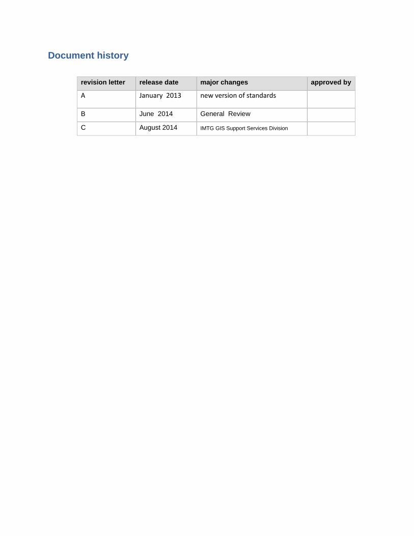
Document history
revision letter release date major changes approved by
A January 2013 new version of standards
B June 2014 General Review
C August 2014 IMTG GIS Support Services Division
LAWA Survey and Remote Sensing Standards
Survey_Standards_August_2014 revision letter C revision date August 2014
© X-Spatial LLC, 2014 Status: For Publication i
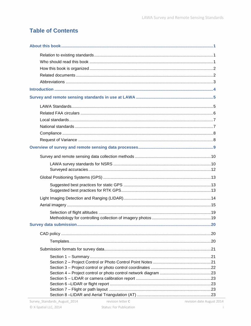
Table of Contents
About this book ...................................................................................................................................... 1
Relation to existing standards ......................................................................................................... 1
Who should read this book ............................................................................................................. 1
How this book is organized ............................................................................................................. 2
Related documents ......................................................................................................................... 2
Abbreviations .................................................................................................................................. 3
Introduction ............................................................................................................................................ 4
Survey and remote sensing standards in use at LAWA .................................................................... 5
LAWA Standards............................................................................................................................. 5
Related FAA circulars ..................................................................................................................... 6
Local standards ............................................................................................................................... 7
National standards .......................................................................................................................... 7
Compliance ..................................................................................................................................... 8
Request of Variance ....................................................................................................................... 8
Overview of survey and remote sensing data processes .................................................................. 9
Survey and remote sensing data collection methods ................................................................... 10
LAWA survey standards for NSRS ...................................................................................... 10 Surveyed accuracies ............................................................................................................ 12
Global Positioning Systems (GPS) ............................................................................................... 13
Suggested best practices for static GPS ............................................................................. 13 Suggested best practices for RTK GPS ............................................................................... 13
Light Imaging Detection and Ranging (LIDAR) ............................................................................. 14
Aerial imagery ............................................................................................................................... 15
Selection of flight altitudes ................................................................................................... 19 Methodology for controlling collection of imagery photos .................................................... 19
Survey data submission ...................................................................................................................... 20
CAD policy .................................................................................................................................... 20
Templates ............................................................................................................................. 20
Submission formats for survey data.............................................................................................. 21
Section 1 – Summary ........................................................................................................... 21 Section 2 – Project Control or Photo Control Point Notes ................................................... 21 Section 3 – Project control or photo control coordinates ..................................................... 22 Section 4 – Project control or photo control network diagram ............................................. 23 Section 5 – LIDAR or camera calibration report .................................................................. 23 Section 6 –LIDAR or flight report ......................................................................................... 23 Section 7 – Flight or path layout .......................................................................................... 23 Section 8 –LIDAR and Aerial Triangulation (AT) ................................................................. 23
LAWA Survey and Remote Sensing Standards
Survey_Standards_August_2014 revision letter C revision date August 2014
© X-Spatial LLC, 2014 Status: For Publication ii
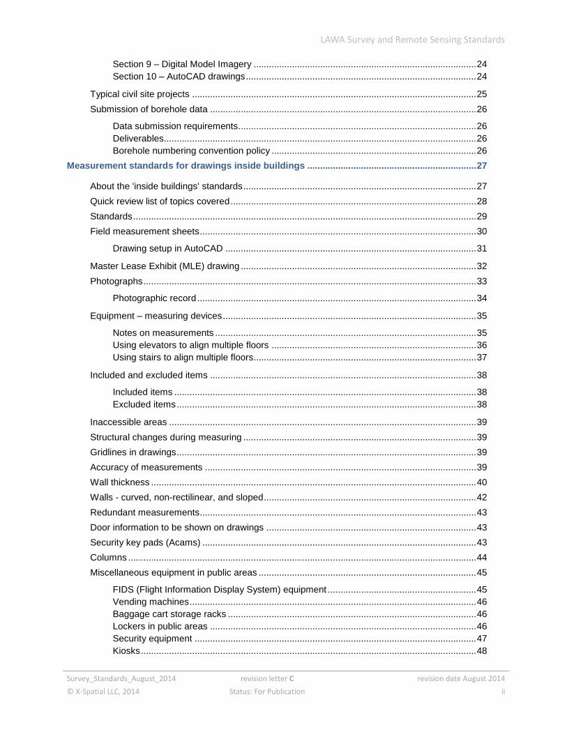
Section 9 – Digital Model Imagery ....................................................................................... 24 Section 10 – AutoCAD drawings .......................................................................................... 24
Typical civil site projects ............................................................................................................... 25
Submission of borehole data ........................................................................................................ 26
Data submission requirements ............................................................................................. 26 Deliverables.......................................................................................................................... 26 Borehole numbering convention policy ................................................................................ 26
Measurement standards for drawings inside buildings .................................................................. 27
About the 'inside buildings' standards ........................................................................................... 27
Quick review list of topics covered ................................................................................................ 28
Standards ...................................................................................................................................... 29
Field measurement sheets ............................................................................................................ 30
Drawing setup in AutoCAD .................................................................................................. 31
Master Lease Exhibit (MLE) drawing ............................................................................................ 32
Photographs .................................................................................................................................. 33
Photographic record ............................................................................................................. 34
Equipment – measuring devices ................................................................................................... 35
Notes on measurements ...................................................................................................... 35 Using elevators to align multiple floors ................................................................................ 36 Using stairs to align multiple floors....................................................................................... 37
Included and excluded items ........................................................................................................ 38
Included items ...................................................................................................................... 38 Excluded items ..................................................................................................................... 38
Inaccessible areas ........................................................................................................................ 39
Structural changes during measuring ........................................................................................... 39
Gridlines in drawings ..................................................................................................................... 39
Accuracy of measurements .......................................................................................................... 39
Wall thickness ............................................................................................................................... 40
Walls - curved, non-rectilinear, and sloped ................................................................................... 42
Redundant measurements ............................................................................................................ 43
Door information to be shown on drawings .................................................................................. 43
Security key pads (Acams) ........................................................................................................... 43
Columns ........................................................................................................................................ 44
Miscellaneous equipment in public areas ..................................................................................... 45
FIDS (Flight Information Display System) equipment .......................................................... 45 Vending machines ................................................................................................................ 46 Baggage cart storage racks ................................................................................................. 46 Lockers in public areas ........................................................................................................ 46 Security equipment .............................................................................................................. 47 Kiosks ................................................................................................................................... 48

LAWA Survey and Remote Sensing Standards
Survey_Standards_August_2014 revision letter C revision date August 2014
© X-Spatial LLC, 2014 Status: For Publication iii
Areas not enclosed or defined by walls ........................................................................................ 48

LAWA Survey and Remote Sensing Standards
Survey_Standards_August_2014 revision letter C revision date August 2014
© X-Spatial LLC, 2014 Status: For Publication iv
THIS PAGE IS INTENTIONALLY LEFT BLANK
LAWA Survey and Remote Sensing Standards
Survey_Standards_August_2014 revision letter C revision date August 2014
© X-Spatial LLC, 2014 Status: For Publication page 1 of 48
About this book
The standards described in this document are provided to help LAWA staff, surveyors,
consultants and project partners prepare and exchange survey information for LAWA
projects.
By using these standards, LAWA will achieve a standardized approach to spatial data
management and related record document(s) that will bring many benefits to both the
organization and its staff. These benefits include, but are not limited to:
consistent and more reliable data that will lead to more informed decision
making
closer integration with other LAWA information systems and LAWA spatial data
users
portability of staff skills
greater interoperability with organizations outside of LAWA
Relation to existing standards
These standards have adopted a series of standards already in use for Surveying and
Remote Sensing developed by NGS, FAA, and LAWA.
Who should read this book
These survey data standards are for use in-house by LAWA and for survey
consultants, in order to ensure all survey drawings and digital CAD data files will meet
LAWA standards.
LAWA Survey and Remote Sensing Standards
Survey_Standards_August_2014 revision letter C revision date August 2014
© X-Spatial LLC, 2014 Status: For Publication page 2 of 48
How this book is organized
After the introduction, this book contains the following chapters and appendixes:
Survey and remote sensing standards in use at LAWA
provides an overview of LAWA specific standards, plus related federal, local, and
national standards
Overview of survey and remote sensing data processes
summarizes survey and remote sensing data collection methods, including best
practices and required levels of accuracy
Survey data submission
outlines LAWA policy for CAD file and other formats to be used when submitting
survey data.
Measurement standards for drawings inside buildings
summarizes a consistent approach toward accurate field measurements for the
creation of new as-built drawings inside buildings.
Related documents
CAD, BIM, GIS, Metadata and EDI standards along with other documentation related
to these standards are available on the LAWA website. LAWA Standard Documents
and Guidelines

LAWA Survey and Remote Sensing Standards
Survey_Standards_August_2014 revision letter C revision date August 2014
© X-Spatial LLC, 2014 Status: For Publication page 3 of 48
Abbreviations
AEGIS Airport Enterprise Geographical Information System
AC Airport Circular (FAA)
AIP Airport Improvement Program
ALM airborne LIDAR mapping
ATLM Airborne Terrestrial LIDAR mapping (alternative name for ALM)
BIM Building Information Modeling
CAD Computer Aided Design and Drafting
EDM electronic data measuring
EFMD Engineering & Facilities Management Division
FAA Federal Aviation Administration
FGDC Federal Geographic Data Committee
FIDS Flight Information Display System
GBL ground based LIDAR
GBLS/GBLM ground based LIDAR scanning/mapping (alternative name for TLM)
GIS Geographic Information System
GISSSD GIS Support Services Division
GPS global positioning systems
IMTG Information Management Technology Group
LAWA Los Angeles World Airports
LAX Los Angeles International Airport
LIDAR light imaging detection and ranging
MCLM mobile compensated LIDAR mapping
MLE Master Lease Exhibits
NGS National Geodetic Survey
NSRS National Spatial Reference System
NSSDA National Standard for Spatial Data Accuracy
ONT Ontario Airport
OPUS Online Positioning User Service (from NGS)
PAC Primary Airport Control Station
PMD Palmdale Airport
RTK GPS Real Time Kinematic GPS
SAC Secondary Airport Control Station
SDSFIE Spatial Data Standard for Facilities Infrastructure and Environment
VNY Van Nuys Airport

LAWA Survey and Remote Sensing Standards
Survey_Standards_August_2014 revision letter C revision date August 2014
© X-Spatial LLC, 2014 Status: For Publication page 4 of 48
Introduction
The Survey and Remote Sensing Standards document is not intended to define a
surveyors method of data collection. These standards apply, whether traditional
theodolites, electronic data measuring (EDM) devices, global positioning systems
(GPS), light imaging detection and ranging (LIDAR) or aerial photography are used.
The surveyor is free to choose the data capture technologies and methods that give
the best results for the type of project and the required levels of accuracy.
This manual is set up in such a way, that the building specific measurements and civil
site specific typical topics are separated. Consultants working on building specific
projects see section “Measurement standards for drawings inside buildings”.
except for some specialized schematics, the software used to produce CAD
drawings is AutoCAD (a recent version)
the unit of measurement used for CAD architectural drawings is the inch
the unit of measurement used for CAD civil drawings is the U.S. foot
project codes are defined by LAWA on a project per project basis
all civil drawings must be created in NAD 83 California State Planes, Zone V, US
Foot coordinate system
all civil drawings will identify the survey epoch used, for example Multi-Year CORS
solution 2011, National adjustment of 2011 (NA2011), Geoid Model GEOID12A
2012
all architectural drawings must use positive values for coordinates
all spatial data must be created in Model Space
all graphical elements must be in Paper Space
These standards and specifications are intended to improve data consistency and
availability of information, and facilitate spatial information dissemination and sharing
within LAWA.
All files and documents submitted to LAWA must be accompanied by a transmittal form holding all required metadata.
Transmittal forms along with other documentation related to these standards are available on the LAWA website. LAWA Standard Documents and Guidelines
LAWA Survey and Remote Sensing Standards
Survey_Standards_August_2014 revision letter C revision date August 2014
© X-Spatial LLC, 2014 Status: For Publication page 5 of 48
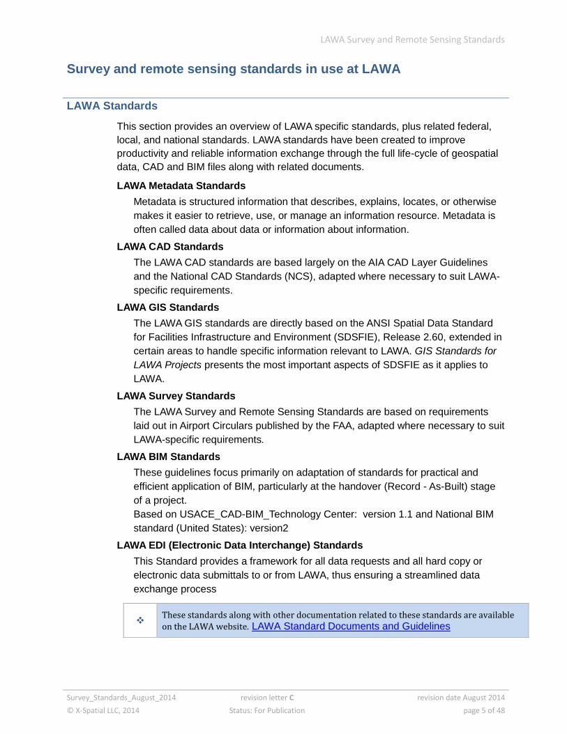
Survey and remote sensing standards in use at LAWA
LAWA Standards
This section provides an overview of LAWA specific standards, plus related federal,
local, and national standards. LAWA standards have been created to improve
productivity and reliable information exchange through the full life-cycle of geospatial
data, CAD and BIM files along with related documents.
LAWA Metadata Standards
Metadata is structured information that describes, explains, locates, or otherwise
makes it easier to retrieve, use, or manage an information resource. Metadata is
often called data about data or information about information.
LAWA CAD Standards
The LAWA CAD standards are based largely on the AIA CAD Layer Guidelines
and the National CAD Standards (NCS), adapted where necessary to suit LAWA-
specific requirements.
LAWA GIS Standards
The LAWA GIS standards are directly based on the ANSI Spatial Data Standard
for Facilities Infrastructure and Environment (SDSFIE), Release 2.60, extended in
certain areas to handle specific information relevant to LAWA. GIS Standards for
LAWA Projects presents the most important aspects of SDSFIE as it applies to
LAWA.
LAWA Survey Standards
The LAWA Survey and Remote Sensing Standards are based on requirements
laid out in Airport Circulars published by the FAA, adapted where necessary to suit
LAWA-specific requirements.
LAWA BIM Standards
These guidelines focus primarily on adaptation of standards for practical and
efficient application of BIM, particularly at the handover (Record - As-Built) stage
of a project.
Based on USACE_CAD-BIM_Technology Center: version 1.1 and National BIM
standard (United States): version2
LAWA EDI (Electronic Data Interchange) Standards
This Standard provides a framework for all data requests and all hard copy or
electronic data submittals to or from LAWA, thus ensuring a streamlined data
exchange process
These standards along with other documentation related to these standards are available
on the LAWA website. LAWA Standard Documents and Guidelines
LAWA Survey and Remote Sensing Standards
Survey_Standards_August_2014 revision letter C revision date August 2014
© X-Spatial LLC, 2014 Status: For Publication page 6 of 48
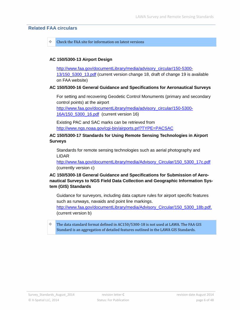
Related FAA circulars
Check the FAA site for information on latest versions
AC 150/5300-13 Airport Design
http://www.faa.gov/documentLibrary/media/advisory_circular/150-5300-
13/150_5300_13.pdf (current version change 18, draft of change 19 is available
on FAA website)
AC 150/5300-16 General Guidance and Specifications for Aeronautical Surveys
For setting and recovering Geodetic Control Monuments (primary and secondary
control points) at the airport
http://www.faa.gov/documentLibrary/media/advisory_circular/150-5300-
16A/150_5300_16.pdf (current version 16)
Existing PAC and SAC marks can be retrieved from
http://www.ngs.noaa.gov/cgi-bin/airports.prl?TYPE=PACSAC
AC 150/5300-17 Standards for Using Remote Sensing Technologies in Airport
Surveys
Standards for remote sensing technologies such as aerial photography and
LIDAR
http://www.faa.gov/documentLibrary/media/Advisory_Circular/150_5300_17c.pdf
(currently version c)
AC 150/5300-18 General Guidance and Specifications for Submission of Aero-
nautical Surveys to NGS Field Data Collection and Geographic Information Sys-
tem (GIS) Standards
Guidance for surveyors, including data capture rules for airport specific features
such as runways, navaids and point line markings.
http://www.faa.gov/documentLibrary/media/Advisory_Circular/150_5300_18b.pdf.
(current version b)
The data standard format defined in AC150/5300-18 is not used at LAWA. The FAA GIS
Standard is an aggregation of detailed features outlined in the LAWA GIS Standards.
LAWA Survey and Remote Sensing Standards
Survey_Standards_August_2014 revision letter C revision date August 2014
© X-Spatial LLC, 2014 Status: For Publication page 7 of 48
Local standards
City of Los Angeles, Bureau of Engineering Manual Part J – Survey
Based on traditional survey methods (theodolite measurements), but also covers
certain safety issues such as testing for gas in manholes.
http://eng.lacity.org/techdocs/survey_man/Survey_Manual.pdf
State of California standards
All cadastral surveys must comply with all State of California regulations
Coordinates are based on the California Coordinate System of 1983 (CCS83),
Zone 5. US Foot
Orthometric Elevations use the North American Vertical Datum of 1988 (NAVD 88)
National standards
National standards are to be followed only when other standards (LAWA, State of
California, or FAA) do not provide guidance. Surveyors must have LAWA approval
before implementing national standards in a LAWA project.
Digital Photogrammetry: An Addendum to the Manual of Photogrammetry,
Chapter 3
American Society for Photogrammetry and Remote Sensing (ASPRS) publication
ASCE C - I 38 -02
Standard Guideline for the Collection and Depiction of Existing Subsurface Util-
ity Data – Section 5, Quality Levels of Service Attributes, A through D
FGDC-STD-008-1999
Content Standards for Digital Ortho-Imagery, 1999
Federal Geographic Data Committee, Subcommittee on Base Cartographic Data
http://www.fgdc.gov/standards/projects/FGDC-standards-projects/framework-
data-standard/GI_FrameworkDataStandard_Part2_DigitalOrthoimagery.pdf
Engineering & Design Photogrammetric Mapping, 2002
U.S. Army Corps of Engineers (USACE 2002)
http://publications.usace.army.mil/publications/eng-manuals/EM_1110-1-
1000_sec/EM_1110-1-1000.pdf
Spatial Data Standard for Facilities, Infrastructure, and Environment
U.S. Army Engineer Research and Development Center, CADD/GIS Technology
Center (SDSFIE)
http://www.sdsfie.org/
LAWA Survey and Remote Sensing Standards
Survey_Standards_August_2014 revision letter C revision date August 2014
© X-Spatial LLC, 2014 Status: For Publication page 8 of 48
Compliance
Having timely up to date, accurate, fully compliant data available to the LAWA
community forms an integral part of planning within any project. The aim of these
standards is to ensure a smooth data transfer of information into the LAWA geospatial
data base and efficient data maintenance through the complete data lifecycle.
Accordingly, the terms and conditions of a LAWA contract require compliance with
these standards.
Failure to comply with these standards may result in organizations being back-
charged for any financial costs incurred by LAWA for rectifying inconsistencies and
errors
The individual or organization submitting the files is also responsible for ensuring that
all links between non-graphic data and graphic data, and all relationships between
database tables, shall be preserved or automatically reconstructed when data is
transferred to the LAWA GIS environment.
Request of Variance
Compliance with the LAWA standards and data deliverables demands are the
cornerstone of achieving trustworthy and relevant data.
Suggestions for improvements or extensions to these standards and demands are
encouraged, to meet unforeseen requirements and as a way to improve effectiveness
and clarify any ambiguities; any such deviation must be approved by LAWA, in
advance and in writing. . Requests need to be submitted on the “Request for
variance” form, this form along with other documentation related to these standards
are available on the LAWA website. LAWA Standard Documents and Guidelines
See EDI for standards governing data submitted to LAWA, this along with other documentation related to these standards are available on the LAWA website. LAWA Standard Documents and Guidelines

LAWA Survey and Remote Sensing Standards
Survey_Standards_August_2014 revision letter C revision date August 2014
© X-Spatial LLC, 2014 Status: For Publication page 9 of 48
Overview of survey and remote sensing data processes
The LAWA Survey and Remote Sending Standards cover items such as:
setting airport geodetic control points or temporary monuments
topographical surveys
LIDAR surveys
aerial photogrammetric projects
Projects at LAWA that receive AIP grant funds must follow the most recent versions of
the survey and submission requirements laid out in FAA Advisory Circulars
AC 150/5300/16, AC 150/5300-17 and AC 150/5300-18.
The data standard format defined in AC150/5300-18 is not used at LAWA. The FAA
GIS Standard is an aggregation of detailed features outlined in the LAWA GIS
Standard.
The following items required by the FAA must also be provided to LAWA:
imagery plans
survey quality control plans
any survey and remote sensing submissions required under the FAA Airport GIS
program
At the beginning of any project, LAWA will provide the surveyor with all necessary or
available digital files in AutoCAD .dwg format, plus any relevant LAWA documentation
related to survey standards. LAWA will also provide a plot of existing data within the
area to be surveyed, if the project specifications require this.
LAWA requires that all survey data returns are provided both in hard copy and digital
AutoCAD .dwg format. Returns follow the file breakdown and standards as set out in
the LAWA CAD standards and the LAWA survey and remote sensing standards.
Where the returns are to be delivered incrementally, each subsequent submission
after the first contains only the features that were not included in any previous
submission. Submission 3, for example, isolates only the features that have not been
previously included in submissions 1 and 2. Each digital submission is accompanied
by a Transmittal letter and a plot of the data in the digital files.
At the end of a project which has used a series of submissions, LAWA must be
provided with a final report. This report is accompanied by a complete set of final
digital .dwg files, including a final survey point data file, and a plot of the data in the
digital files.
LAWA Survey and Remote Sensing Standards
Survey_Standards_August_2014 revision letter C revision date August 2014
© X-Spatial LLC, 2014 Status: For Publication page 10 of 48
LAWA must always be provided with a project related comprehensive survey report at
completion, even if the project does not require a FAA Airport GIS submission. This
report must include all information necessary to confirm the integrity of the survey,
and an outline of all processes involved and used to collect the survey data.
Any outstanding or unresolved problems, for example unopened
manholes/catchbasins or features still unidentified, are noted in the final report so that
appropriate action can be taken by LAWA.
General airport control points can be obtained from LAWA upon request
The final digital files submitted contain all features collected during the project, and
reflect any changes/updates made during the project. All civil site or utility projects
that submit survey data to LAWA must be tied to the NSRS. For all internal building
surveys, see section “Measurement standards for drawings inside buildings”.
Survey and remote sensing data collection methods
All civil site or utility projects that submit survey data to LAWA must be tied to the
NSRS.
A second order horizontal and vertical control network has been established at the
site.
This network consists of approximately 109 survey monuments and temporary
benchmarks. In some areas, above ground features were pre-marked with paint to
meet municipal utility color coding standards and help feature recognition during data
capture. These PAC and SAC control marks can be obtained from the NGS. Any
additional LAWA control points can be obtained from LAWA.
LAWA survey standards for NSRS
Obtain the current list of existing control points at use at LAWA. PAC and SAC data
can be obtained from the NGS
http://www.ngs.noaa.gov/cgi-bin/airports.prl?TYPE=PACSAC
Geodetic verification
After recovering the PAC and SAC data, the contractor will conduct two
independent GPS sessions, each 10 minutes or longer, between the existing
stations. The collected data will be post-processed and adjusted while
constraining to PAC data.
The results of the network adjustment will be compared to published values for
each SAC, and should identify any possible disturbance. The computed distance
from the PAC must agree to within ± 3 cm in distance; the difference in ellipsoidal
height must agree to within ± 4 cm, and the difference in orthometric height must
agree to within ± 5 cm.
The contractor must contact LAWA for guidance in repositioning the SAC point (or
points) if any discrepancy outside these tolerances is found.

LAWA Survey and Remote Sensing Standards
Survey_Standards_August_2014 revision letter C revision date August 2014
© X-Spatial LLC, 2014 Status: For Publication page 11 of 48
Positional accuracy
Shall be tested and reported following the guidance in the National Standard for
Spatial Data Accuracy (FGDC-STD-007.3-1998). All projects require independent
NSSDA check points as defined in AC 150/5300-17C.
for small projects, one independent check point is required
for large projects such as aerial control for the entire airport, five
NSSDA check points are required
Check points for GPS
When using remote sensing technologies, additional check points provide a
means of verifying the georeferencing of the data. Collect and provide additional
NGS Online Positioning User Service (OPUS) check points within the project
area, for an independent check of accuracies. Do not use these check points as
part of georeferencing solution for the data. Submit a copy of the OPUS and GPS
solution for each check point.
Check point traverse for theodolite surveys
If using traditional theodolite survey methods create a separate traverse that ties
your check point traverse to your main project adjusted traverse and provide the
comparison of coordinate values of the tie points.

LAWA Survey and Remote Sensing Standards
Survey_Standards_August_2014 revision letter C revision date August 2014
© X-Spatial LLC, 2014 Status: For Publication page 12 of 48
Surveyed accuracies
accuracy requirements shown are relative to the PACs and SACs or other
approved airport control points used for the project
hard surfaces and features: 0.03 feet horizontally and 0.02 feet vertically
original ground and graded dirt areas: 0.10 feet horizontally and vertically
features captured by aerial photography from various scales over the runways
and built up areas attain accuracy’s of 0.66 feet horizontally and 1.0 feet vertically.
Federal Geographic Data Committee (FGDC) standard FGDC-STD-008-1999
compliant metadata assigned during the survey contains the accuracy and date of
data capture of the feature or point.
LAWA Survey and Remote Sensing Standards
Survey_Standards_August_2014 revision letter C revision date August 2014
© X-Spatial LLC, 2014 Status: For Publication page 13 of 48
Global Positioning Systems (GPS)
GPS has become the primary method for data collection of most surveys. Here are a
set of best practices that should be followed when doing work at LAWA.
Suggested best practices for static GPS
establish new station (PAC, SAC or temporary control, etc.) in accordance with
FAA AC150/5300-17
use observation times based on required accuracy and baseline length
complete GPS log sheet for all observations
set GPS receivers to a 15° elevation mask
utilize ground planes for all control observations
utilize fixed height tripods or rover poles for all observations (mitigating instrument
height errors)
inspect and calibrate plumb of fixed height tripods and rover poles before
performing observations
monitor receiver during all session to ensure uninterrupted and good quality GPS
data
verify fixed height tripod height prior to all sessions
capture required hand-held digital photographs for specific station types (see AC
150/5300-18b section 1.5.2)
Suggested best practices for RTK GPS
create a new observation (DC) file on a daily basis
set base station PDOP mask to 5.0
set base station antenna mask for 15°
set base station RMS limits to 0.20
set base station to collect IN-FILL data for the duration of full day at 15-second
epochs
periodically check base station for plumb and battery power supply
periodically check in other existing control for accuracy check
LAWA Survey and Remote Sensing Standards
Survey_Standards_August_2014 revision letter C revision date August 2014
© X-Spatial LLC, 2014 Status: For Publication page 14 of 48
Light Imaging Detection and Ranging (LIDAR)
Specific standards and recommended practices must apply when using LIDAR
scanners.
LIDAR scanners are used for a variety of survey tasks and currently fall into four
principle categories:
ground based LIDAR (GBL), generally used for measuring atmospheric
composition
airborne LIDAR mapping (ALM), also known as airborne terrestrial LIDAR
mapping (ATLM)
mobile compensated LIDAR mapping (MCLM)
terrestrial LIDAR mapping (TLM),sometimes referred to as ground based LIDAR
scanning (GBLS or GBLM)
LIDAR scanning technologies, regardless of type, are line-of-sight instruments and
unable to detect what is not visible to the sensor. Be aware of your scanner’s
limitations and local terrain variations, and plan your project to cover any potential
gaps or shadows in data coverage.
LIDAR projects are to follow all requirements outlined in AC 150/5300-17 Standards
for Using Remote Sensing Technologies in Airport Surveys
LAWA Survey and Remote Sensing Standards
Survey_Standards_August_2014 revision letter C revision date August 2014
© X-Spatial LLC, 2014 Status: For Publication page 15 of 48
Aerial imagery
Specific standards and recommended practices apply when working with aerial
imagery.
LAX has been flown with three different flying heights. Make use of existing photo
control from previous projects where possible.
Existing flight lines will be used when any new aerial photo is acquired. Only models
that require updating will be re-triangulated.
The imagery flight missions can consist of any of these three flying altitudes,
dependent upon the Project Statement of Work:
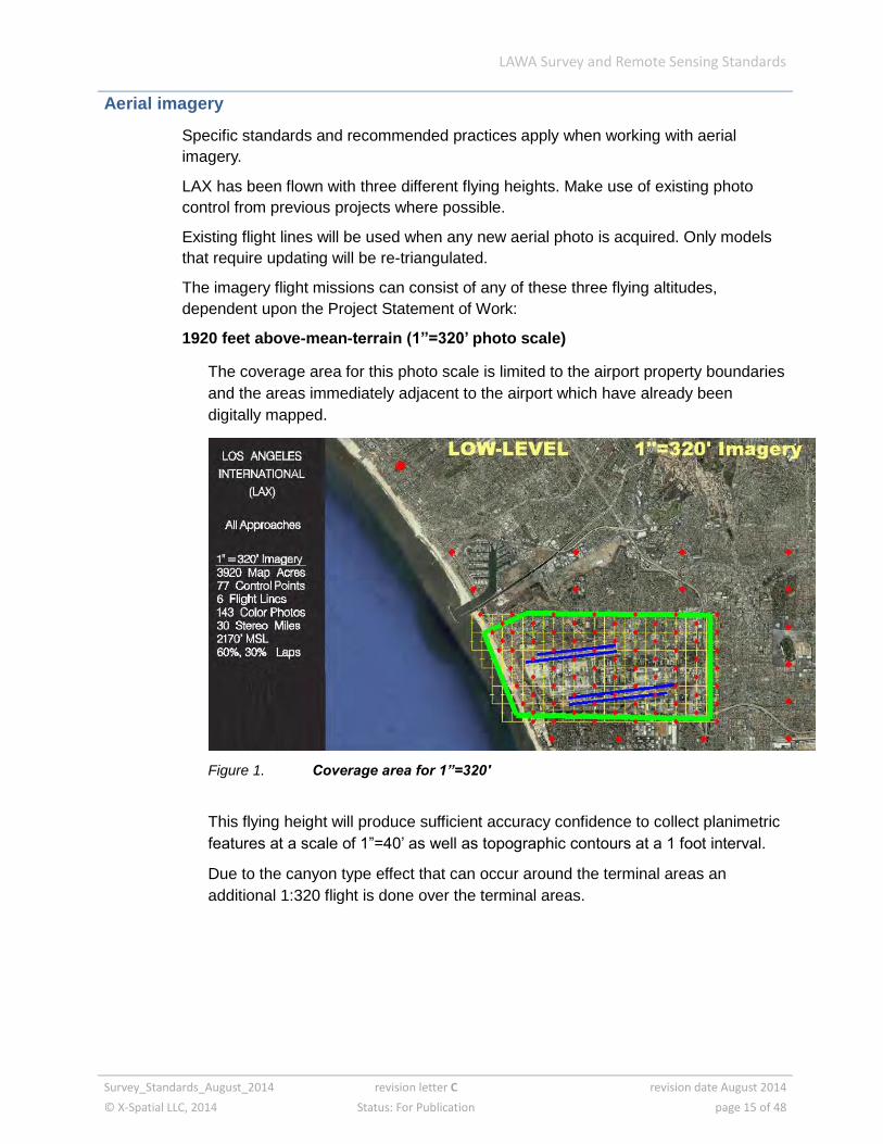
1920 feet above-mean-terrain (1”=320’ photo scale)
The coverage area for this photo scale is limited to the airport property boundaries
and the areas immediately adjacent to the airport which have already been
digitally mapped.
Figure 1. Coverage area for 1”=320'
This flying height will produce sufficient accuracy confidence to collect planimetric
features at a scale of 1”=40’ as well as topographic contours at a 1 foot interval.
Due to the canyon type effect that can occur around the terminal areas an
additional 1:320 flight is done over the terminal areas.

LAWA Survey and Remote Sensing Standards
Survey_Standards_August_2014 revision letter C revision date August 2014
© X-Spatial LLC, 2014 Status: For Publication page 16 of 48
Figure 2. Terminal Area Model Limits
Figure 3. Terminal Area Flight line locations
This imagery will be used to produce orthophotography having a ground pixel
resolution of 0.20’ suitable for a 1”=40’ scale
LAWA Survey and Remote Sensing Standards
Survey_Standards_August_2014 revision letter C revision date August 2014
© X-Spatial LLC, 2014 Status: For Publication page 17 of 48
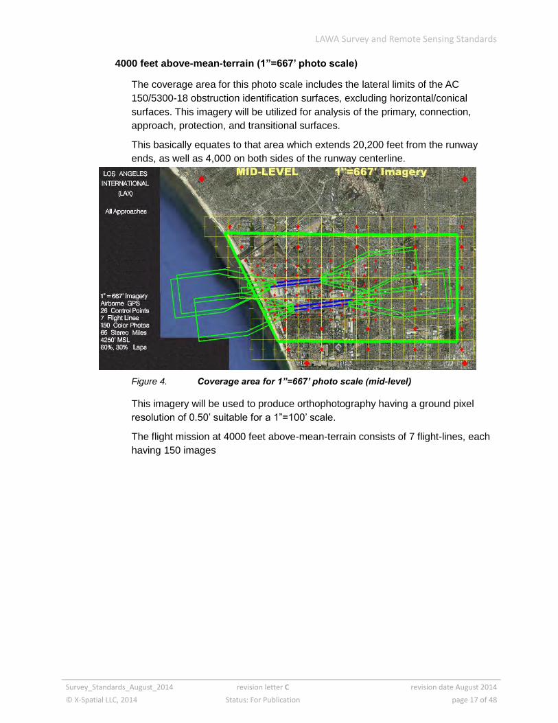
4000 feet above-mean-terrain (1”=667’ photo scale)
The coverage area for this photo scale includes the lateral limits of the AC
150/5300-18 obstruction identification surfaces, excluding horizontal/conical
surfaces. This imagery will be utilized for analysis of the primary, connection,
approach, protection, and transitional surfaces.
This basically equates to that area which extends 20,200 feet from the runway
ends, as well as 4,000 on both sides of the runway centerline.
Figure 4. Coverage area for 1”=667’ photo scale (mid-level)
This imagery will be used to produce orthophotography having a ground pixel
resolution of 0.50’ suitable for a 1”=100’ scale.
The flight mission at 4000 feet above-mean-terrain consists of 7 flight-lines, each
having 150 images

LAWA Survey and Remote Sensing Standards
Survey_Standards_August_2014 revision letter C revision date August 2014
© X-Spatial LLC, 2014 Status: For Publication page 18 of 48
9000 feet above-mean-terrain (1”=1500’ photo scale)
The coverage area for this photo scale will span the entire lateral limits of the
vertically guided surfaces area. It will be utilized in analyzing the horizontal and
conical obstruction identification surfaces.
Figure 5. Coverage area for 1”=1500’ photo scale (high-level)
This imagery will be used to produce orthophotography having a ground pixel
resolution of 1.0’ suitable for a 1”=200’ scale.
The flight mission at 9000 feet above-mean-terrain consists of 6 flight-lines, with a
total of 72 images.
LAWA Survey and Remote Sensing Standards
Survey_Standards_August_2014 revision letter C revision date August 2014
© X-Spatial LLC, 2014 Status: For Publication page 19 of 48
Selection of flight altitudes
The flight altitudes mentioned above will allow for collection of obstruction data,
planimetric features, and topographic data within the accuracies prescribed by section
5 of AC150/5300-18B.
This circular requires the following levels of accuracy
horizontal position of obstructions within +/-20 feet
within the primary, connection, transitional, protection, and approach surfaces,
vertical orthometric height of obstacles within +/-3 feet
within the horizontal and conical surfaces, orthometric height of obstacles within
+/-10 feet.
All three of the planned photo scales were selected to ensure these accuracies will be
met using remote sensing. The flying heights are designed to deliver a level of detail
which will allow these imagery layouts to be utilized in future projects.
Methodology for controlling collection of imagery photos
The LAWA photo control network consists of 109 control points and 5 independent
check points.
The position for each of the five check points was determined with OPUS software
from the NGS. These check points were not utilized in the control solution of the
imagery.
The 109 control points are distributed throughout the photo area, assuring quality
control of the entire imagery area. A special concentration of control points is utilized
in the immediate vicinity of the airport, where accuracy requirements are more
stringent and where the planimetric and topographic data will be collected.

LAWA Survey and Remote Sensing Standards
Survey_Standards_August_2014 revision letter C revision date August 2014
© X-Spatial LLC, 2014 Status: For Publication page 20 of 48
Survey data submission
This section outlines LAWA policy for CAD file and other formats to be used when
submitting survey data.
CAD policy
It is the policy of the Los Angles World Airways (LAWA) that all CAD deliverables
submitted to LAWA shall be in a AutoCAD *.dwg file format, structured in accordance
with LAWA CAD
The LAWA CAD standards are based largely on the AIA CAD Layer Guidelines and
the National CAD Standards (NCS), adapted where necessary to suit LAWA-specific
requirements. The document CAD Standards for LAWA Projects is available from the
LAWA web site at www.lawa.org/laxdev/Handbook.aspx. These standards currently
cover .dwg files only.
The LAWA Standards include, but are not limited to: file naming conventions, drawing
numbers, file and level structure, fonts, line colors, line weights, symbols, patterns
and reference files.
The CAD system in use at LAWA for drawing/data management, which is also the
basis of facility management systems, is AutoCAD by Autodesk.
If any secondary consultant uses a CAD package other than AutoCAD, it shall be the
responsibility of the prime consultant to ensure all CAD data submitted to LAWA is
structured in accordance with LAWA CAD Standards.
Templates
Project partners and subcontractors who need to implement the CAD standards for
LAWA projects can download templates to provide a working environment based on
the LAWA CAD Standards. Each template (.dwt file) defines the layers for a specific
discipline. Sample title blocks can also be downloaded
LAWA Survey and Remote Sensing Standards
Survey_Standards_August_2014 revision letter C revision date August 2014
© X-Spatial LLC, 2014 Status: For Publication page 21 of 48
Submission formats for survey data
The submission format for survey data is based on AC 150/5300-17, with slight
modifications. The following directory structure is to be used when submitting data.
1. Summary
2. Project control or photo control notes
3. Project control coordinates
4. Photo control network diagram
5. LIDAR & camera calibration report
6. LIDAR path or flight report
7. LIDAR path or flight layout
8. LIDAR or aerial triangulation
9. Digital model imagery
10. AutoCAD drawings
LIDAR projects are to follow all requirements outlined in AC 150/5300-17.
An explanation and sample data requirements for each directory follows.
Section 1 – Summary
This section contains project summary and summary of any deviations
Summary Report should contain a report of any issues that could affect the project,
such as problems with Control points, accuracy issues, site access problems, or
changes in flight lines or camera during a flight. The report should ensure that any
deviations from the project plan are annotated and properly recorded due to unusual
circumstances or problems, equipment malfunctions, changes to proposed
methodologies/equipment or any deviations from these specifications.
SUBMISSION FORMAT .pdf
Section 2 – Project Control or Photo Control Point Notes
This section contains survey documentation.
Station location sketch and visibility diagrams are required for each point listed in
the control coordinate listing of the files. All station location sketch and visibility
reports are to be uniquely numbered and correspond to the hand held photographs
supplied, and numbers match the point numbers in the project control or photo control
coordinate listing.
SUBMISSION FORMAT .txt, Excel
LAWA Survey and Remote Sensing Standards
Survey_Standards_August_2014 revision letter C revision date August 2014
© X-Spatial LLC, 2014 Status: For Publication page 22 of 48
Hand held photographs are required for each control point, navaid or runway end.
Each point should have one hand held photo (up close) taken from 5-6 feet away and
one hand held photo taken from 10-30 feet away. All photos include the airport name
or airport call letters and survey point number.
SUBMISSION FORMAT .pdf or .jpg
Rinex Version of all GPS station data is required in RAW format as below
Raw GPS input files aaaaddds.xxx aaaa = alphanumeric 4-character station identifier
ddd = day of year
s = session
yy = year of observations
xxx = receiver-dependent file extension (for
example .DAT, .EPH, .ION, or .MES)
Rinex Sample Raw observation is shown below
RINEX2 Observation File aaaaddds.yyo
NSSDA check Points
Raw GPS observations must be provided for all points listed as the NSSDA check
points
5 check points are required for FAA photogrammetric imagery projects
submit OPUS results for each temporary GPS station including the NSSDA check
points
SUBMISSION FORMAT .txt, Excel, .pdf or .jpg
Section 3 – Project control or photo control coordinates
This section contains survey data and Airborne GPS data collected during the
acquisition of GPS and Aerial Photography GPS (ABGPS) data.
Provide an ASCII text file of the final imagery control point values identifying any
changes from the remote sensing plan, as illustrated in Table 3-2 of AC 150/5300-
17C. This section should only include the coordinate values (easting, northing,
elevation) for the control points being used in the project and the five OPUS check
points
SUBMISSION FORMAT .txt, Excel, .pdf or .jpg
LAWA Survey and Remote Sensing Standards
Survey_Standards_August_2014 revision letter C revision date August 2014
© X-Spatial LLC, 2014 Status: For Publication page 23 of 48
Section 4 – Project control or photo control network diagram
This section contains the ground control diagram.
Provide a KML or PDF depicting all control stations the data used in geo-referencing
the project including information regarding their tie to the NSRS
SUBMISSION FORMAT .pdf, .jpg or .kml
Section 5 – LIDAR or camera calibration report
This section contains a .pdf of the calibration report
There is no standard format for the calibration reports. However, they must contain, at
a minimum, the following information:
date the calibration was performed
name of the person, company, or organization responsible for performing the
calibration
methods used to perform the calibration
final calibration parameters or corrections determined through the calibration
procedures.
discussion of the results
sensor maintenance reports with maintenance history of the sensors used in data
collection
Calibration submission for LIDAR equipment must follow AC 150/5300-17, Section 5.4
“What are the system calibration requirements for using LIDAR to collect airport data”
SUBMISSION FORMAT .pdf or .jpg
Section 6 –LIDAR or flight report
Only required for Aerial Photogrammetric projects
SUBMISSION FORMAT .pdf or .jpg
Section 7 – Flight or path layout
This directory contains a diagram that depicts the flight paths or paths used in LIDAR
data acquisition, plus altitudes that were flown during imagery acquisition.
SUBMISSION FORMAT .pdf or .jpg
Section 8 –LIDAR and Aerial Triangulation (AT)
This directory contains AT reports, spreadsheets, or ASCII files that describe the
triangulation results for project including LIDAR and aerial photography projects as
defined in AC 150/5300-17c section 3.4.d.7.
SUBMISSION FORMAT .txt, Excel or .pdf
LAWA Survey and Remote Sensing Standards
Survey_Standards_August_2014 revision letter C revision date August 2014
© X-Spatial LLC, 2014 Status: For Publication page 24 of 48
Section 9 – Digital Model Imagery
This directory contains raw stereo images (TIF images) or LIDAR point clouds
SUBMISSION FORMAT Tiff or point cloud
Section 10 – AutoCAD drawings
AutoCAD submission best practices (.dwg)
Project partners and subcontractors who need to implement the CAD standards
for LAWA projects can download templates to provide a working environment
based on the LAWA CAD Standards. Each template (.dwt file) defines the layers
for a specific discipline. Sample title blocks can also be downloaded.
AutoCAD Best Practices
all spatial data must be created in model space
all graphical elements must be in paper space
the unit of measurement used for cad civil drawings is the u.s. foot
all civil drawings must be created in nad 83 california state planes, zone v, us
foot coordinate system
proper orientation of point features should be maintained wherever possible
underground services should be connected wherever possible.
for any feature that cannot be identified by the field crew, enter the point into
the digital file as an unidentified feature, using the block ID from the LAWA
block library. At the same time, a LAWA EFMD engineer or GIS specialist
should be notified of the point in question so that an investigation can be
started by LAWA to obtain identification for the feature. A photograph, taken by
the field crew of the unidentifiable point and forwarded to LAWA, will aid in the
identification process. When identification has been obtained, LAWA will notify
the surveyor so that the proper symbology for the point can be input into the
digital file.
if a new feature has been collected that does not match any existing feature, a
LAWA representative should be notified. The representative will then determine
the proper symbology and feature number to be used and forward this to the
surveyor for input in the digital file.
survey plans submitted to LAWA should be legible at the plotted scale, with the
spot elevations not appearing too dense in nature
LAWA Survey and Remote Sensing Standards
Survey_Standards_August_2014 revision letter C revision date August 2014
© X-Spatial LLC, 2014 Status: For Publication page 25 of 48
digital spot elevations are to be structured so the elevations of a specified
interval are on the appropriate layer within the CAD file. The remaining
elevations must be placed on a separate CAD layer specified in the LAWA
CAD Standards. This will allow for spot heights to be shown on any drawing
without being too dense in appearance, yet still contain all collected spot
elevations within the file which can be used for design, planning, etc. purposes.
when submitting a CAD file, the settings for the relevant layers should be
“tuned on” and “thawed”
Typical civil site projects
All drawings submitted with survey data will have a file-name starting with V- , as
outlined in the CAD Layer Assignment table for LAWA projects.
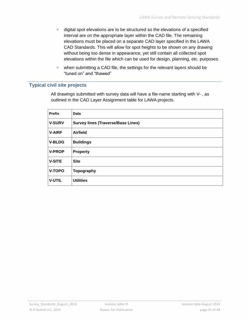
Prefix Data
V-SURV Survey lines (Traverse/Base Lines)
V-AIRF Airfield
V-BLDG Buildings
V-PROP Property
V-SITE Site
V-TOPO Topography
V-UTIL Utilities
LAWA Survey and Remote Sensing Standards
Survey_Standards_August_2014 revision letter C revision date August 2014
© X-Spatial LLC, 2014 Status: For Publication page 26 of 48
Submission of borehole data
Data submission requirements
All borehole locations are to be submitted geo-referenced according to LAWA
standards. LAWA will then use this data to update the digital graphics database for
the design and management of the facility.
Deliverables
hard copy of the geo-technical report describing project findings and test
results including borehole logs and the corresponding hard copy site plan
drawings
ASCII file with x,y and z coordinates and number of each borehole
Note: Although it is not a requirement, it would be preferable to be given all site plan
drawings in an AutoCAD.dwg format.
reports in PDF Format
Borehole numbering convention policy
Each borehole must be numbered consisting of the Project Number and a sequential
log number. If a borehole is not associated with a project, the number 999 will be
assigned as the project number.
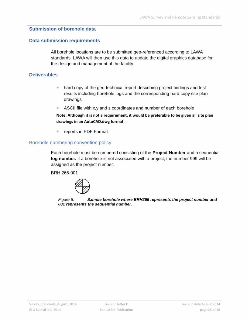
BRH 265-001
Figure 6. Sample borehole where BRH265 represents the project number and 001 represents the sequential number.
LAWA Survey and Remote Sensing Standards
Survey_Standards_August_2014 revision letter C revision date August 2014
© X-Spatial LLC, 2014 Status: For Publication page 27 of 48
Measurement standards for drawings inside buildings
The buildings digital graphics database was built up from hard-copy drawings for
many of the existing airport buildings, including terminals, administration building,
central work shop, central utility plant, fire hall/maintenance garage and so on. These
drawings included architectural floor plans and a combination of reflected ceiling
plans, structural, electrical and mechanical information.
These files use the same coordinate system as the site data. Therefore, the buildings
and their corresponding data sets fit directly on top of the site information.
Other airport buildings, including aircraft hangars, cargo buildings, airline
administrative buildings and so on. are not included in the database because these
tenants manage their own facilities. Drawings of these buildings are either digitized or
re-drawn if they are required for a LAWA project, and are ultimately added to the
building digital graphics database.
About the 'inside buildings' standards
These standards provide consistent tools toward accurate field measurements for the
creation of new as-built drawings that will, in-turn, be used in facilities management to
create up-to-date verifiably accurate Master Lease Exhibits (MLE) of various
terminals. Using these standards, one would expect to be able to duplicate a
measurement at random, and get a result reasonably similar to the original
measurement.
Measurements will be used to create accurate as-built drawings in AutoCAD (.dwg)
and in GIS (.shp) format. The new as-built drawings are to adhere to the latest LAWA
CAD Standards published on the LAWA web site and detailed in the LAWA Design
and Construction handbook.
All measuring and the resulting drawings are to follow the Standard parameters as set
forth in this document. Field measurements and factual observations duly
documented shall take precedence over existing As-Built Drawings or any other
existing construction documents.
Methods described in this Standard are the result of several years of field experience
measuring and drawing several airport terminal structures over 100,000 square feet
per floor. The intention is to provide proven methods to avoid common errors, remove
the necessity to repeat the entire learning curve and provide new or novice measuring
teams with basic rules helpful to this end. The experienced measuring team will
recognize many shared methods, and may appreciate this measuring standard as a
useful tool.
LAWA Survey and Remote Sensing Standards
Survey_Standards_August_2014 revision letter C revision date August 2014
© X-Spatial LLC, 2014 Status: For Publication page 28 of 48
Quick review list of topics covered
paper requirements
as-built drawing requirements
drawing CAD setup for as-built drawings
photographs
equipment acceptable for use on this project
elevators, stairs, and aligning multiple floors
included items
excluded items
rounding off of field measurements
rounding off of drawings
accuracy in measuring and drawing
wall thicknesses accurately measured
dimension and measuring points
walls – odd angles, vertically, horizontally, and curved
redundant measurements
door information
security key pads (also known as Acams)
column diameter
areas undefined by walls or other enclosures
LAWA Survey and Remote Sensing Standards
Survey_Standards_August_2014 revision letter C revision date August 2014
© X-Spatial LLC, 2014 Status: For Publication page 29 of 48
Standards
The standards defined and illustrated in this chapter cover:
field measurement sheets
drawing setup in AutoCAD
master lease exhibit (MLE) drawing
photographs
equipment – measuring devices
aligning multiple floors
included and excluded items
inaccessible areas
structural changes during measuring
gridlines in drawings
accuracy of measurements
wall thickness
door dimension points
walls - curved, non-rectilinear, and sloped
redundant measurements
door information to be shown on drawings
security key pads (Acams)
columns
miscellaneous equipment in public areas
areas not enclosed or defined by walls

LAWA Survey and Remote Sensing Standards
Survey_Standards_August_2014 revision letter C revision date August 2014
© X-Spatial LLC, 2014 Status: For Publication page 30 of 48
Field measurement sheets
Field measurement sheets can be either of:
small scale sector map
all sectors per level, for one terminal
large scale sector drawing
individual sectors, for measuring
Figure 1. Sector map showing total floor plan
Figure 2. Single sector showing partial floor plan
LAWA Survey and Remote Sensing Standards
Survey_Standards_August_2014 revision letter C revision date August 2014
© X-Spatial LLC, 2014 Status: For Publication page 31 of 48
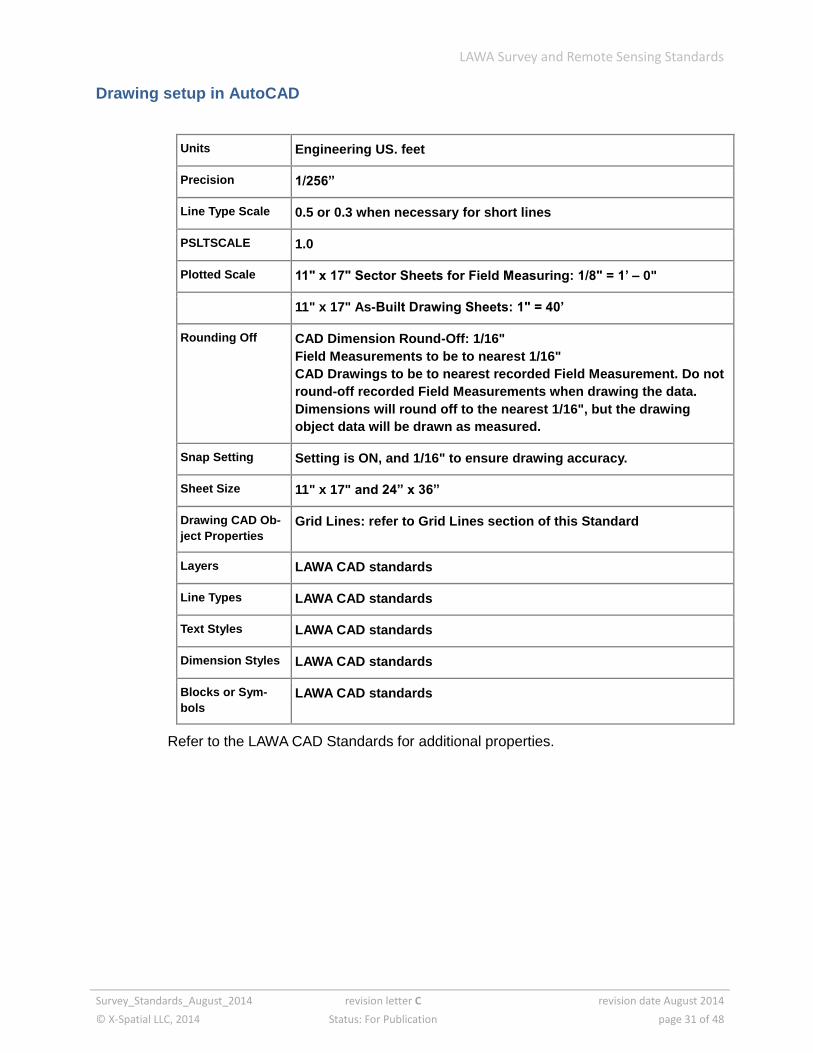
Drawing setup in AutoCAD
Units Engineering US. feet
Precision 1/256”
Line Type Scale 0.5 or 0.3 when necessary for short lines
PSLTSCALE 1.0
Plotted Scale 11" x 17" Sector Sheets for Field Measuring: 1/8" = 1’ – 0"
11" x 17" As-Built Drawing Sheets: 1" = 40’
Rounding Off CAD Dimension Round-Off: 1/16"
Field Measurements to be to nearest 1/16"
CAD Drawings to be to nearest recorded Field Measurement. Do not
round-off recorded Field Measurements when drawing the data.
Dimensions will round off to the nearest 1/16", but the drawing
object data will be drawn as measured.
Snap Setting Setting is ON, and 1/16" to ensure drawing accuracy.
Sheet Size 11" x 17" and 24” x 36”
Drawing CAD Ob-
ject Properties
Grid Lines: refer to Grid Lines section of this Standard
Layers LAWA CAD standards
Line Types LAWA CAD standards
Text Styles LAWA CAD standards
Dimension Styles LAWA CAD standards
Blocks or Sym-
bols
LAWA CAD standards
Refer to the LAWA CAD Standards for additional properties.
LAWA Survey and Remote Sensing Standards
Survey_Standards_August_2014 revision letter C revision date August 2014
© X-Spatial LLC, 2014 Status: For Publication page 32 of 48
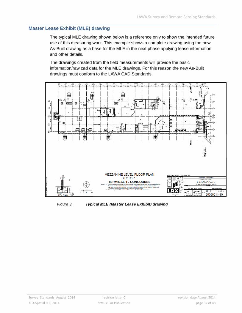
Master Lease Exhibit (MLE) drawing
The typical MLE drawing shown below is a reference only to show the intended future
use of this measuring work. This example shows a complete drawing using the new
As-Built drawing as a base for the MLE in the next phase applying lease information
and other details.
The drawings created from the field measurements will provide the basic
information/raw cad data for the MLE drawings. For this reason the new As-Built
drawings must conform to the LAWA CAD Standards.
Figure 3. Typical MLE (Master Lease Exhibit) drawing
LAWA Survey and Remote Sensing Standards
Survey_Standards_August_2014 revision letter C revision date August 2014
© X-Spatial LLC, 2014 Status: For Publication page 33 of 48
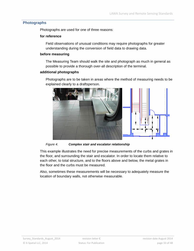
Photographs
Photographs are used for one of three reasons:
for reference
Field observations of unusual conditions may require photographs for greater
understanding during the conversion of field data to drawing data.
before measuring
The Measuring Team should walk the site and photograph as much in general as
possible to provide a thorough over-all description of the terminal.
additional photographs
Photographs are to be taken in areas where the method of measuring needs to be
explained clearly to a draftsperson.
Figure 4. Complex stair and escalator relationship
This example illustrates the need for precise measurements of the curbs and grates in
the floor, and surrounding the stair and escalator. In order to locate them relative to
each other, to total structure, and to the floors above and below, the metal grates in
the floor and the curbs must be measured.
Also, sometimes these measurements will be necessary to adequately measure the
location of boundary walls, not otherwise measurable.

LAWA Survey and Remote Sensing Standards
Survey_Standards_August_2014 revision letter C revision date August 2014
© X-Spatial LLC, 2014 Status: For Publication page 34 of 48
Photographic record
Maintain a stored record of all photographs taken. This may include maps of where
the photographs were taken. An example is shown below.
Figure 5. Arrival Public Lobby – overhead FIDS
LAWA Survey and Remote Sensing Standards
Survey_Standards_August_2014 revision letter C revision date August 2014
© X-Spatial LLC, 2014 Status: For Publication page 35 of 48
Equipment – measuring devices
minimum device accuracy to be 1/16"
Acceptable measuring devices are:
manual: recommend 100’ and 30’ metal tapes
digital: Leika Disto Classic or equal
LIDAR based survey
Sonar based measuring equipment, and non-metallic tapes and tapes that may
stretch with use, are not acceptable.
Notes on measurements
measurements less than 18"
Because of the nature of the two primary measuring instruments, metal tape and
digital, the metal tape is to be used for all measurements less than 18".
measurements greater than 100’
Great care must be taken to accurately mark the incremental beginnings and
endings. Use structural landmarks whenever possible, and accurately measure
the landmarks, and their relative positions to other notable landmarks in the
vicinity.
measuring in sunlight
Certain measurements such as outdoors in sunlight should be done with the metal
tape.
LAWA Survey and Remote Sensing Standards
Survey_Standards_August_2014 revision letter C revision date August 2014
© X-Spatial LLC, 2014 Status: For Publication page 36 of 48
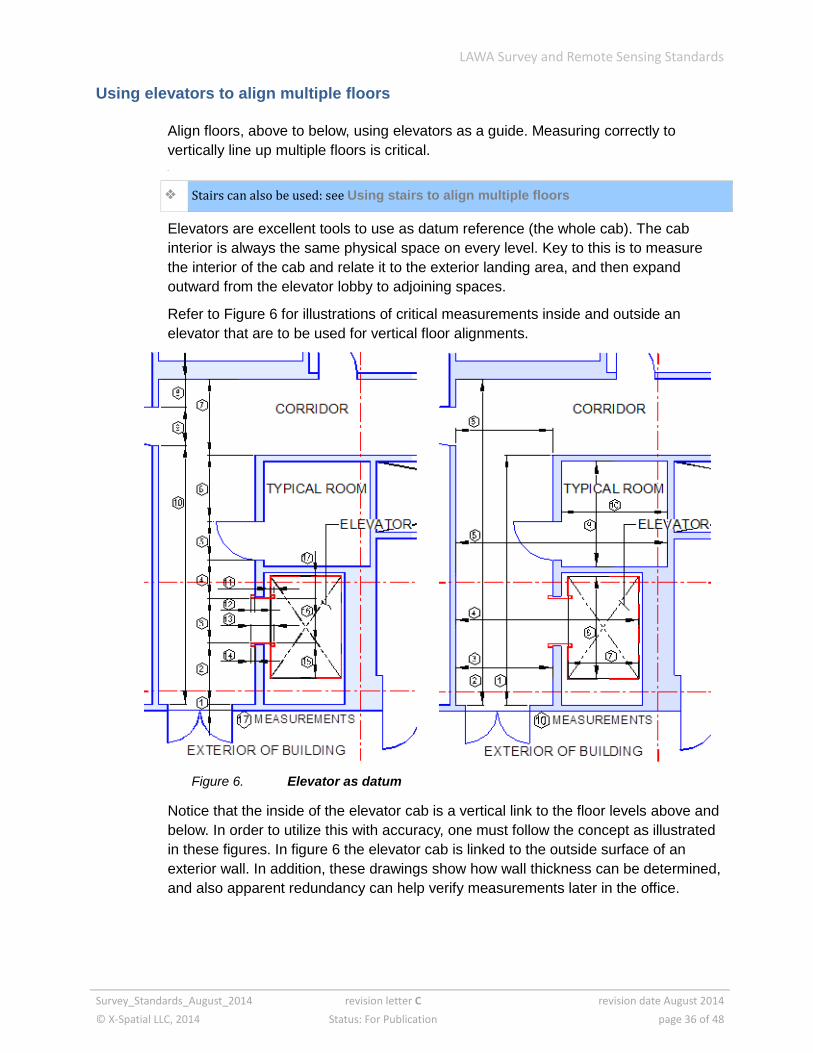
Using elevators to align multiple floors
Align floors, above to below, using elevators as a guide. Measuring correctly to
vertically line up multiple floors is critical.
Stairs can also be used: see Using stairs to align multiple floors
Elevators are excellent tools to use as datum reference (the whole cab). The cab
interior is always the same physical space on every level. Key to this is to measure
the interior of the cab and relate it to the exterior landing area, and then expand
outward from the elevator lobby to adjoining spaces.
Refer to Figure 6 for illustrations of critical measurements inside and outside an
elevator that are to be used for vertical floor alignments.
Figure 6. Elevator as datum
Notice that the inside of the elevator cab is a vertical link to the floor levels above and
below. In order to utilize this with accuracy, one must follow the concept as illustrated
in these figures. In figure 6 the elevator cab is linked to the outside surface of an
exterior wall. In addition, these drawings show how wall thickness can be determined,
and also apparent redundancy can help verify measurements later in the office.
LAWA Survey and Remote Sensing Standards
Survey_Standards_August_2014 revision letter C revision date August 2014
© X-Spatial LLC, 2014 Status: For Publication page 37 of 48
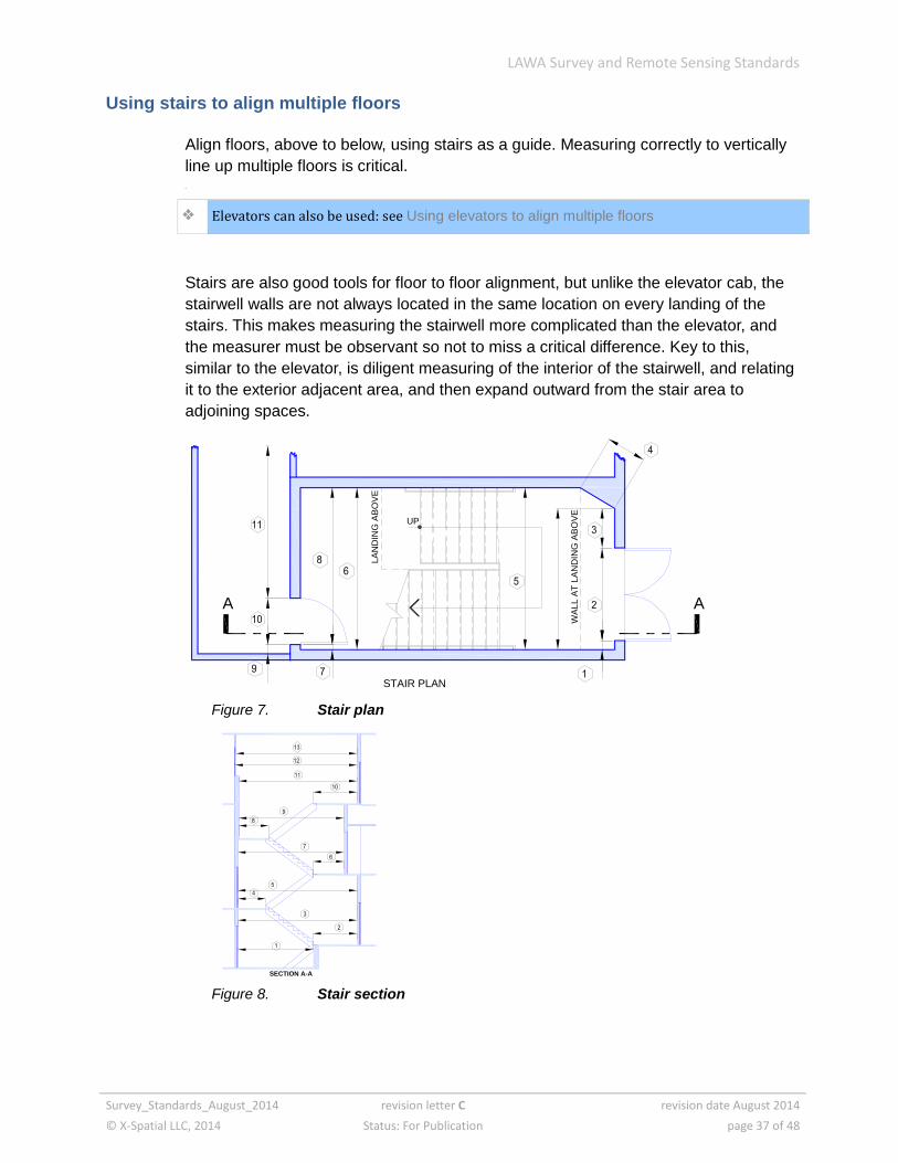
Using stairs to align multiple floors
Align floors, above to below, using stairs as a guide. Measuring correctly to vertically
line up multiple floors is critical.
Elevators can also be used: see Using elevators to align multiple floors
Stairs are also good tools for floor to floor alignment, but unlike the elevator cab, the
stairwell walls are not always located in the same location on every landing of the
stairs. This makes measuring the stairwell more complicated than the elevator, and
the measurer must be observant so not to miss a critical difference. Key to this,
similar to the elevator, is diligent measuring of the interior of the stairwell, and relating
it to the exterior adjacent area, and then expand outward from the stair area to
adjoining spaces.
Figure 7. Stair plan
Figure 8. Stair section
UP
WA
LL A
T L
AN
DIN
G A
BO
VE
LA
ND
ING
AB
OV
E
A A
STAIR PLAN
SECTION A-A

LAWA Survey and Remote Sensing Standards
Survey_Standards_August_2014 revision letter C revision date August 2014
© X-Spatial LLC, 2014 Status: For Publication page 38 of 48
Included and excluded items
This list is for the purpose of answering just what is and is not to be measured or
noted, in addition to the obvious physical structure of the airport terminals.
Note any unusual physical features and verify with LAWA FMG Engineers and/or GIS
staff, if they are to be documented. When questioning or deciding on items not listed
in this section, always verify the status with LAWA before proceeding with your own
decisions. All questions are to be in writing with a clear date of asking, the name of
the requestor, and who it was sent to, along with the question itself. All written
material should be in a readable condition.
Included items
all vending machines found in any public area
all lockers found in public areas
free standing kiosks such as might be used by a flower retailer, candy vendor
or others
baggage handling equipment such as carousels in the baggage arrival areas
trash compaction machinery, whether private or LAWA owned
free standing portable offices
There are offices of this type throughout the airport facility. All of them are to be
measured and noted on the drawings.
all FIDS (Flight Information Display System) monitors
Show the correct number of monitors installed in a single cabinet. Measure and
locate the cabinets, or note the monitors when flush mounted within a wall. There
should be an accommodation in the wall thickness for these, or there may be a
monitor that protrudes from the wall on the interior space.
Security check points, Immigration and agricultural examination tables and
booths
other items not listed here, but included as they occur
Excluded items
in restrooms: plumbing fixtures, stall partitions, mirrors, or counter tops
in various public areas: movable, freestanding objects
private non-LAWA equipment of any kind, unless LAWA specifically requests a
usually excluded item to be included
Verify with LAWA exactly what other items are excluded from measurement and data
documentation as to their existence and/or location and size.
LAWA Survey and Remote Sensing Standards
Survey_Standards_August_2014 revision letter C revision date August 2014
© X-Spatial LLC, 2014 Status: For Publication page 39 of 48
Inaccessible areas
All areas, rooms, and spaces are to be measured. Any of these found to be
inaccessible are to be documented and reported to LAWA in a timely manner.
Structural changes during measuring
Often during a measuring assignment, a Lessee or LAWA may make changes to a
structure that was already measured, or is about to be measured while this change is
taking place. Request access if necessary, and measure the newly constructed
structure. If the measuring of this area is completed prior to the beginning of the
change, verify with LAWA or measuring supervisors whether this change will be
included in the new as-built drawings or will the measuring team ignore the change.
Each of these is subject to inclusion or exclusion in the measurement process, as a
separate decision.
If at all possible for the measuring team, always try to get the latest data on the
structure.
Gridlines in drawings
Grid lines in field sector sheets and new as-built drawings shall be drawn orthogonally
located and labeled as represented on the existing as-built reference construction
documents.
Accuracy of measurements
single measurement
½" maximum for any single measurement regardless of the distance measured.
cumulative measurements
strings of measurements, such as a series of rooms along a corridor, shall be
within ½" in either direction, larger or smaller than a single measurement along an
adjacent space such as an adjacent corridor. This permits a tolerance of 1", but
limits it to ½" greater or smaller than the total dimension. This limit is required to
assure that as these cumulative spaces are drawn, that they do not produce over-
lapping areas, or an interior that extends beyond the exterior of the building.
multiple or redundant measurements
these are useful to verify accuracy and are often needed in the case of single or
cumulative measurements.
LAWA Survey and Remote Sensing Standards
Survey_Standards_August_2014 revision letter C revision date August 2014
© X-Spatial LLC, 2014 Status: For Publication page 40 of 48
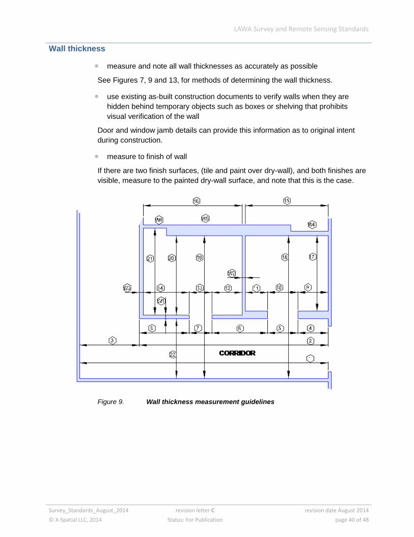
Wall thickness
measure and note all wall thicknesses as accurately as possible
See Figures 7, 9 and 13, for methods of determining the wall thickness.
use existing as-built construction documents to verify walls when they are
hidden behind temporary objects such as boxes or shelving that prohibits
visual verification of the wall
Door and window jamb details can provide this information as to original intent
during construction.
measure to finish of wall
If there are two finish surfaces, (tile and paint over dry-wall), and both finishes are
visible, measure to the painted dry-wall surface, and note that this is the case.
Figure 9. Wall thickness measurement guidelines

LAWA Survey and Remote Sensing Standards
Survey_Standards_August_2014 revision letter C revision date August 2014
© X-Spatial LLC, 2014 Status: For Publication page 41 of 48
Notes:
interior rooms located along an adjacent corridor need to have their location
relative to each other and the corridor defined accurately and thoroughly
potential errors occur when a wall changes thickness inside a room, and
dimensions 20 or 21 is not noted or measured
wall thickness errors may produce errors in adjacent space locations and
subsequently cause an encroachment into other spaces
Wall thickness calculation examples:
W1 = 19 – (22 + 20)
W2 = (4 + 5 + 6 + 7 + 12) – (15 + 16)
W3 = 1 – (3 – 4 + 5 + 6 + 7 +12)
W4, W5 & W6 show a potential for error
Lesson: be observant and diligent
LAWA Survey and Remote Sensing Standards
Survey_Standards_August_2014 revision letter C revision date August 2014
© X-Spatial LLC, 2014 Status: For Publication page 42 of 48
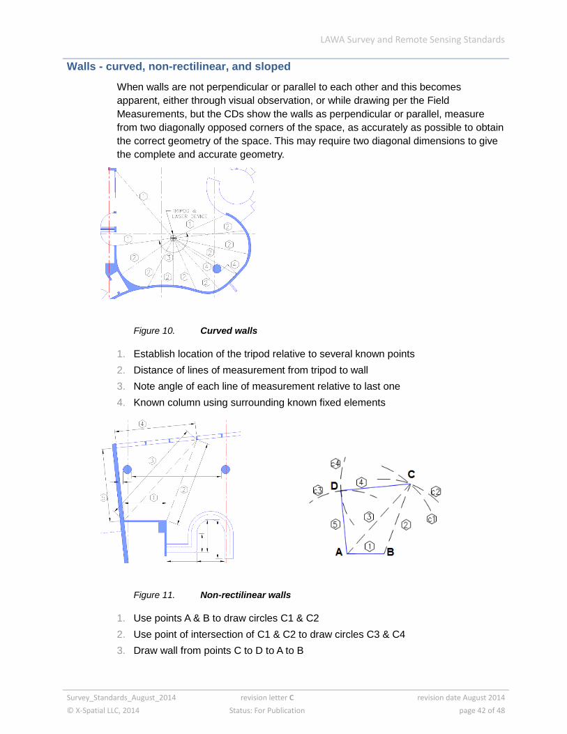
Walls - curved, non-rectilinear, and sloped
When walls are not perpendicular or parallel to each other and this becomes
apparent, either through visual observation, or while drawing per the Field
Measurements, but the CDs show the walls as perpendicular or parallel, measure
from two diagonally opposed corners of the space, as accurately as possible to obtain
the correct geometry of the space. This may require two diagonal dimensions to give
the complete and accurate geometry.
Figure 10. Curved walls
1. Establish location of the tripod relative to several known points
2. Distance of lines of measurement from tripod to wall
3. Note angle of each line of measurement relative to last one
4. Known column using surrounding known fixed elements
Figure 11. Non-rectilinear walls
1. Use points A & B to draw circles C1 & C2
2. Use point of intersection of C1 & C2 to draw circles C3 & C4
3. Draw wall from points C to D to A to B
LAWA Survey and Remote Sensing Standards
Survey_Standards_August_2014 revision letter C revision date August 2014
© X-Spatial LLC, 2014 Status: For Publication page 43 of 48
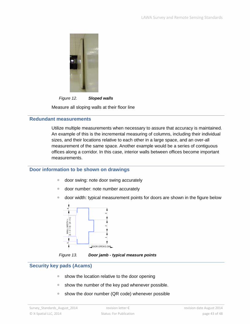
Figure 12. Sloped walls
Measure all sloping walls at their floor line
Redundant measurements
Utilize multiple measurements when necessary to assure that accuracy is maintained.
An example of this is the incremental measuring of columns, including their individual
sizes, and their locations relative to each other in a large space, and an over-all
measurement of the same space. Another example would be a series of contiguous
offices along a corridor. In this case, interior walls between offices become important
measurements.
Door information to be shown on drawings
door swing: note door swing accurately
door number: note number accurately
door width: typical measurement points for doors are shown in the figure below
Figure 13. Door jamb - typical measure points
Security key pads (Acams)
show the location relative to the door opening
show the number of the key pad whenever possible.
show the door number (QR code) whenever possible
DOOR OPEN'G DIM
32
1
4 W
ALL W
IDT
H =
(1 +
2 +
3)
- (4
+ 5
) 5
LAWA Survey and Remote Sensing Standards
Survey_Standards_August_2014 revision letter C revision date August 2014
© X-Spatial LLC, 2014 Status: For Publication page 44 of 48
Columns
locate columns relative to adjacent columns, and to adjacent walls or windows.
Do NOT rely on existing As-Built construction drawings to locate the columns.
measure the finish surface of the column
This may be the actual structural column or it may be an applied finish, or box around
the column.
To determine the as-built diameter of round columns, measure the circumference and
calculate the diameter using the formula
Diameter (D) = Circumference (C) divided by pi or D = C ÷ 3.14

LAWA Survey and Remote Sensing Standards
Survey_Standards_August_2014 revision letter C revision date August 2014
© X-Spatial LLC, 2014 Status: For Publication page 45 of 48
Miscellaneous equipment in public areas
This category concerns items such as:
FIDS (Flight Information Display System) equipment
vending machines
baggage cart storage racks
lockers in public areas
security equipment
kiosks
wifi antennas
internet charging stations
FIDS (Flight Information Display System) equipment
Figure 14. FIDS examples
Use ceiling and floor tile grids when measuring the object is not feasible or accuracy
is not possible with a tape or laser device.
LAWA Survey and Remote Sensing Standards
Survey_Standards_August_2014 revision letter C revision date August 2014
© X-Spatial LLC, 2014 Status: For Publication page 46 of 48
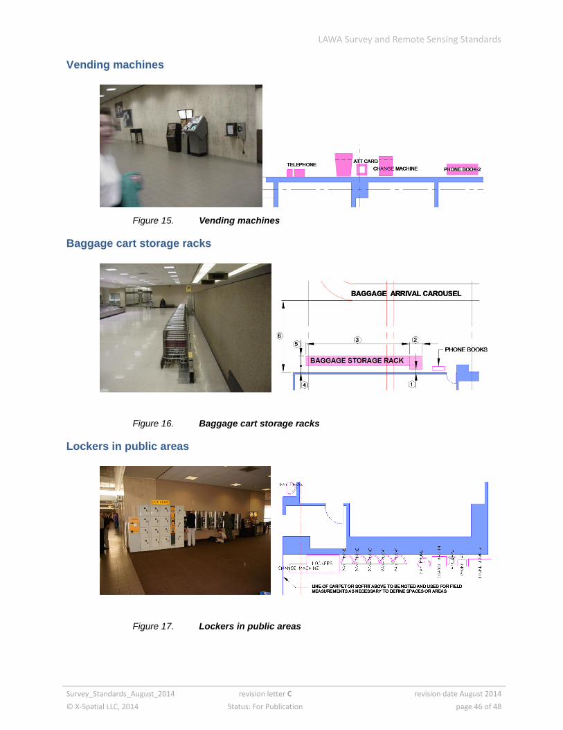
Vending machines
Figure 15. Vending machines
Baggage cart storage racks
Figure 16. Baggage cart storage racks
Lockers in public areas
Figure 17. Lockers in public areas
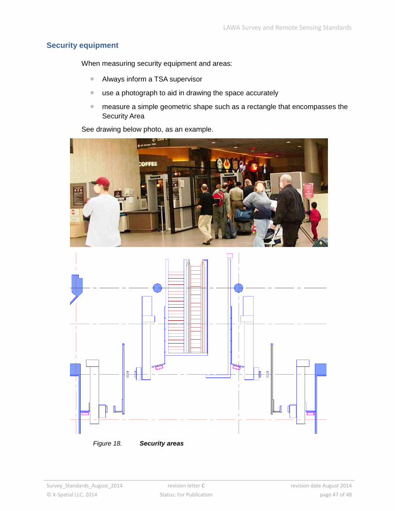
LAWA Survey and Remote Sensing Standards
Survey_Standards_August_2014 revision letter C revision date August 2014
© X-Spatial LLC, 2014 Status: For Publication page 47 of 48
Security equipment
When measuring security equipment and areas:
Always inform a TSA supervisor
use a photograph to aid in drawing the space accurately
measure a simple geometric shape such as a rectangle that encompasses the
Security Area
See drawing below photo, as an example.
Figure 18. Security areas
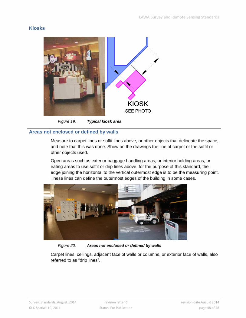
LAWA Survey and Remote Sensing Standards
Survey_Standards_August_2014 revision letter C revision date August 2014
© X-Spatial LLC, 2014 Status: For Publication page 48 of 48
Kiosks
Figure 19. Typical kiosk area
Areas not enclosed or defined by walls
Measure to carpet lines or soffit lines above, or other objects that delineate the space,
and note that this was done. Show on the drawings the line of carpet or the soffit or
other objects used.
Open areas such as exterior baggage handling areas, or interior holding areas, or
eating areas to use soffit or drip lines above. for the purpose of this standard, the
edge joining the horizontal to the vertical outermost edge is to be the measuring point.
These lines can define the outermost edges of the building in some cases.
Figure 20. Areas not enclosed or defined by walls
Carpet lines, ceilings, adjacent face of walls or columns, or exterior face of walls, also
referred to as “drip lines”.