lathes safety, install, maint, service parts manual
TRANSCRIPT

TRAK® TRL LATHES Safety, Installation, Maintenance, Service & Parts List
Covers Non-Current Models:
Document: P/N 24955 Version: 062211
1440P TRAK TRL
1745P TRAK TRL
1440S TRAK TRL 1745S TRAK TRL 1440P Sport 1745P Sport
Southwestern Industries, Inc. 2615 Homestead Place Rancho Dominguez, CA 90220-5610 USA T | 800.421.6875 | F | 310. 764.2668 Service Department: 800.367.3165 e-mail: [email protected] | [email protected] | web: southwesternindustries.com
Copyright © 2008, Southwestern Industries, Inc. All rights are reserved. No part of this publication may be reproduced, stored in a retrieval system, or transmitted, in any form or by any means, mechanical, photocopying, recording or otherwise, without the prior written permission of Southwestern Industries, Inc. While every effort has been made to include all the information required for the purposes of this guide, Southwestern Industries, Inc. assumes no responsibility for inaccuracies or omission and accepts no liability for damages resulting from the use of the information contained in this guide. All brand names and products are trademarks or registered trademarks of their respective holders. Southwestern Industries, Inc. 2615 Homestead Place Rancho Dominguez, CA 90220 Phn 310/608-4422 Fax 310/764-2668 Service Department Phn 800/367-3165 Fax 310/886-8029

i Southwestern Industries, Inc.
TRAK TRL 1440P, 1745P, 1440S, 1745S, and Sport 1440S, & 1745S Service, Installation, Maintenance, Safety, & Parts Lists Manual
Table of Contents 1.0 Safety Specifications 1.1 Safety Publications 1 1.2 Danger, Warning, Caution, Note Labels &
Notices as Used in this Manual 1.3 Safety Precautions 2.0 Installation 2.1 Pre-Check Requirements 6 2.2 Site Preparation
72.2.1 TRL 1440 & TRL 1745 2.3 Floor Plan, Layout & Space Requirements 2.4 Uncrating 2.5 Shortages: Inventory Checklist 2.6 Installation Instructions & Checklist 2.7 Machine Specifications 2.8 ProtoTRAK SL Control Hardware 2.9 Lifting and/or Moving the Machine 2.9.1 1440 2.9.2 1745 2.10 Cleaning 2.11 Leveling 2.11.1 All Models 2.12 Electrical Connection 2.12.1 Phase Converters 2.13 Mounting the Display Pendant 2.14 Cable Interconnections 2.15 Lubrication System
2.15.1 Headstock 2.15.2 Automatic Lubrication Pump 2.15.3 Tailstock 2.15.4 Miscellaneous Information 2.15.5 Caution
2.16 Cutting the Test Part 3.0 Installation Checkout 3.1 Visual Inspection 31 3.2 Inspection of DRO Operation 3.3 Cutting the Test Part 3.4 Measurement of the Test Part 4.0 Troubleshooting by Symptom 4.1 Problems Relating to Machining Results 33 4.1.1 Poor Finish 4.1.2 Turning Diameters Out of Round
4.1.3 Cutting Taper 4.1.4 Parts Have Incorrect Dimensions 4.1.5 Threading Problems
4.2 Problems Regarding Motion of Machine 4.2.1 Run Away Axis 4.2.2 Slow Down Axis 4.2.3 Axis Will Not Jog 4.2.4 Axis Motor Motion Is Not Smooth 4.2.5 Vibration in Motion 4.2.6 Searching Axis
4.3 Problems Relating to Operation of Control 4.3.1 Display Blanks 4.3.2 Bad Picture on Display 4.3.3 Keyboard Lockup 4.3.4 Fault X or Z 4.3.5 Problems Reading Floppy Disk
4.3.6 System Will Not Turn on or Boot Up
4.3.7 System Reboots by Itself 4.3.8 System Shuts Off 4.3.9 Will Not Hold Calibration 4.3.11 E-Stop Error
4.4 Problem with the Measurements 4.4.1 X and Z-Axis Measurements
Do Not Repeat 4.4.2 X and Z-Axis Measurements
Are Not Accurate 4.4.3 The DRO Is Not Counting 4.4.4 X and Z-Axis DRO Counting in
Wrong Direction 4.4.5 X and Z-Axis Electric Handwheels
Turn in Wrong Directon 4.5 Problems with the Machine Tool 4.5.1 Spindle Stalls or Turns Off During
Machining 4.5.2 Spindle Motor Hums or Will
Not Run 4.5.3 Spindle Runs Backwards 4.5.4 Excessive Gearbox Noise 4.5.5 Headstock is Leaking Oil 4.5.6 Tailstock Barrel is Stiff
5.0 Diagnostics 5.1 The Machine Tool & Set-Up 48 5.1.1 Leveling 5.1.2 A Special Word About X Gibs 5.1.3 Lubrication 5.1.4 Machining Set-Up 5.2 The Mechanical Drive Train (X and Z) 5.3 Computer/Pendant Diagnostics 5.3.1 Computer/Pendant -- SL 5.3.2 Computer/Pendant – L2
5.3.3 Pendant – LX2 5.3.4 Computer Module 5.3.5 Checking Floppy Drive by
Formatting a Disk 5.4 Motor Diagnostics
5.4.1 Cable Connections 5.4.2 To Check the Motor Encoders 5.4.3 Encoder Counts to Pendant 5.4.4 Moving Problem From One Axis
to Another 5.5 Servo Drivers 5.6 Electrical
ii Southwestern Industries, Inc.
TRAK TRL 1440P, 1745P, 1440S, 1745S, and Sport 1440S, & 1745S Service, Installation, Maintenance, Safety, & Parts Lists Manual
5.6.1 Checking A/C Voltage 5.6.2 Checking Fuses
5.6.3 Fuse Indicator Light 5.6.4 Cable Breakout Box Connections 5.6.5 Cable Connections 5.6.6 Electrical Box 5.7 Door Interlock 5.8 Service Codes 5.8.1 Software Codes 5.8.2 Machine Set-up Codes 5.8.3 Diagnostic Codes 5.8.4 Operator Defaults/Options Codes 6.0 Procedures for Replacements
& Maintenance 6.1 Replacements 68
6.1.1 Motor Replacement 6.1.2 Servo Driver Replacement 6.1.3 Computer Module Replacement –
SL 6.1.4 Computer Module Replacement –
LX2 6.1.5 System Flash Disk Replacement 6.1.6 Cable Routing on Machine 6.1.7 Electronic Handwheels & Jogstick 6.1.8 Z Axis Electronic Handwheel
Removal 6.1.9 X Axis Electronic Handwheel
Removal 6.1.10 Jogstick Removal 6.1.11 Spindle Forward/Reverse Switch 6.1.12 Cable Routing in Electrics Box
6.1.13 Spindle Encoder Replacement 6.1.14 Brake Removal 6.1.15 Spindle Drive Belt Tightening/
Replacement 6.1.16 Spindle Motor Removal 6.1.17 X Axis Ballscrew Encoder Assembly 6.1.18 X Axis Motor Removal 6.1.19 X Axis Ballscrew Removal 6.1.20 Installing Angular Contact Bearings 6.1.21 Servo Driver Removal 6.1.22 Z Axis Motor 6.1.21 Z Axis Ballscrew Encoder Assembly 6.1.24 Z Axis Ballscrew Removal 6.1.25 Align Z Axis Ballscrew Assembly 6.1.26 Headstock Taper Adjustment 6.1.27 Spindle Bearing Preload 6.1.28 Aligning Tailstock to Spindle 6.1.29 Spindle Motor Wiring
6.1.30 1440/1745 Headstock Teardown 6.2 Maintenance 6.2.1 Gib Adjustments 6.2.2 Calibration & Backlash Constants 6.2.3 Lubrication

iii Southwestern Industries, Inc.
TRAK TRL 1440P, 1745P, 1440S, 1745S, and Sport 1440S, & 1745S Service, Installation, Maintenance, Safety, & Parts Lists Manual
List of Figures 2-1 1440 Floor Plan Layout & Space Requirement 2-2 1745 Floor Plan Layout & Space Requirement 2-3 Anchor Bolt Specifications 2-4 Lifting the 1440 2-5 Lifting the 1745 2-6 Leveling 2-7 Electrical Schematic 2-8 1745 Electrical Schematic 2-9 Procedure for Converting Motors 2-10 SL Pendant Cable Connections, Left Side 2-11 SL Pendant, Right Side 2-12 ProtoTRAK L2 Pendant & Switch Box 2-13 L2 Pendant Back 2-14 L2 Connection Box 2-15 ProtoTRAK LX2 Pendant & Switch Box 2-16 LX2 Pendant Display 2-17 LX2 Computer Box 2-18 Lubrication Schematic 3-1 Measuring Test Part 5-1 Electrical Cabinet 6-1 Computer Module Replacement 6-2 Computer Module & Flash Drive
Replacement 6-3 Computer Cabinet Assembly – LX2 6-4 Computer Cabinet Assembly – 1440 & 1745 6-5 Adjusting Brake – All Controls 6-6 Spindle Drive Belt/Motor Mounting 6-7 Angular Contact Bearings 6-8 Headstock Alignment 6-9 Tailstock Alignment 6-10 1440/1745 Spindle Motor Wiring 6-11 Calibration & Backlash Constants 6-12 Calibration Setup 6-13 Draining the Oil Reservoir 6-14 1440 & 1745 Lubrication 6-15 Tailstock Oil 7.0 Drawings and Parts Lists 7-1 1440 Bed & Chip Pan 90 7-2 1745 Bed & Chip Pan 7-3 1440/1745 Door 7-4 1440/1745 SL X Axis Drive Assembly 7-5 1440/1745 SL Z Axis Drive Assembly 7-6 1440 Main Spindle Shaft 7-7 1440 Headstock Pinion & Shaft 7-8 1440 Headstock Controls 7-9 1745 Main Spindle Assembly 7-10 1745 Headstock Pinions & Shaft 7-11 1745 Headstock Control 7-12 Tailstock Assembly 7-13 Tailstock Assembly 7-14 1440 Carriage Assembly 7-15 1745 Carriage Assembly 7-16 Spindle Encoder Drive Assembly 7-17 1440 Steady Rest Assembly 7-18 1745 Steady Rest Assembly 7-19 Apron Assembly Parts Lists, 1440/1745
With LX2 or Sport CNC 7-20 Apron Assembly – 1745/1440, SL 7-21 1440 Pendant Bracket Kit – SL 7-22 1745 Pendant Bracket Kit – SL 7-23 Switch Box – 1440/1745,
L2/LX2 CNC 7-24 TRAK TRL Assembly – 1440/1745 7-25 Z Drive Assembly 7-26 X Axis Drive Assembly – 1440P/1745P
LX2, Sport 7-27 Lubrication Kit for Lathes 7-28 Brake Adjustment – 1745

1 Southwestern Industries, Inc.
TRAK TRL 1440P, 1745P, 1440S, 1745S, and Sport 1440S, & 1745S Service, Installation, Maintenance, Safety, & Parts Lists Manual
1.0 Safety Specifications The safe operation of the TRAK TRL 1440 and 1745 CNC depends on its proper use and the precautions taken by each operator.
• Read and study the TRAK TRL 1440 and 1745 CNC Safety, Programming, Operating, and Care Manual. Be certain that every operator understands the operation and safety requirements of this machine before its use.
• Read and study this TRAK TRL 1440 and 1745 Safety, Installation, Maintenance, Service
& Parts List Manual. Be certain that every operator understands the operation and safety requirements of this machine before servicing.
• Always wear safety glasses and safety shoes.
• Always stop the spindle and check to ensure the CNC control is in the stop mode before
changing or adjusting the tool or workpiece.
• Never wear gloves, rings, watches, long sleeves, neckties, jewelry, or other loose items when operating, or around the machine.
• Use adequate point of operation safeguarding. It is the responsibility of the employer to
provide and ensure point of operation safeguarding per ANSI B11.6-1984.
1.1 Safety Publications Refer to and study the following publications for assistance in enhancing the safe use of this machine: Safety Requirements For The Construction, Care And Use of Lathes (ANSI B11.6-2001). Available from the American National Standards Institute, 11 West 42nd Street, New York, NY 10036. Concepts And Techniques Of Machine Safeguarding (OSHA Publication Number 3067). Available from The Publication Office - O.S.H.A., U.S. Department of Labor, 200 Constitution Avenue, NW, Washington, DC 20210. All other regulations specific to the State in which the machine is installed. 1.2 Danger, Warning, Caution, and Note Labels and Notices
As Used In This Manual DANGER - Immediate hazards that will result in severe personal injury or death. Danger labels on the machine are red in color. WARNING - Hazards or unsafe practices that could result in severe personal injury and/or damage to the equipment. Warning labels on the machine are gold in color. CAUTION - Hazards or unsafe practices that could result in minor personal injury or equipment/product damage. Caution labels on the machine are gold in color.

2 Southwestern Industries, Inc.
TRAK TRL 1440P, 1745P, 1440S, 1745S, and Sport 1440S, & 1745S Service, Installation, Maintenance, Safety, & Parts Lists Manual
NOTE - Call attention to specific issues requiring special attention or understanding.
115/230/440 Volts
Safety & Information Labels Used On The Lathe It is forbidden by OSHA regulations and by law to deface, destroy or
remove any of these labels

3 Southwestern Industries, Inc.
TRAK TRL 1440P, 1745P, 1440S, 1745S, and Sport 1440S, & 1745S Service, Installation, Maintenance, Safety, & Parts Lists Manual
Safety & Information Labels Used On The TRAK TRL 1440 & 1745 Lathe
It is forbidden by OSHA regulations and by law to deface, destroy or remove any of these labels
I00727
4 Southwestern Industries, Inc.
TRAK TRL 1440P, 1745P, 1440S, 1745S, and Sport 1440S, & 1745S Service, Installation, Maintenance, Safety, & Parts Lists Manual
1.3 Safety Precautions
WARNING! Use only chucks which are rated to the maximum RPM of the lathe.
1. Do not operate this machine before the corresponding programming, operating, and care
manual have been studied and understood.
2. Read and study this safety, installation, maintenance, service, & parts list manual. Be certain that every operator understands the operation and safety requirements of this machine before servicing.
3. Do not run this machine without knowing the function of every control key, button, knob,
or handle. Ask your supervisor or a qualified instructor for help when needed.
4. Protect your eyes. Wear approved safety glasses (with side shields) at all times.
5. Don't get caught in moving parts. Before operating this machine, remove all jewelry, including watches and rings, neckties, and any loose-fitting clothing.
6. Keep your hair away from moving parts. Wear adequate safety head gear.
7. Protect your feet. Wear safety shoes with oil-resistant, anti-skid soles, and steel toes.
8. Take off gloves before you start the machine. Gloves are easily caught in moving parts.
9. Remove all tools (wrenches, chuck keys, etc.) from the machine before you start. Loose
items can become dangerous flying projectiles.
10. Never operate any machine tool after consuming alcoholic beverages, or taking strong medications, or while using non-prescription drugs.
11. Protect your hands. Stop the machine spindle and ensure that the CNC control is in the
STOP mode:
• Before changing tools • Before changing parts • Before you clear away the chips, oil or coolant. Always use a chip scraper or
brush • Before you make an adjustment to the part, chuck, coolant nozzle or take
measurements • Before you open safeguards (protective shields, etc.). Never reach for the part,
tool, or fixture around a safeguard.
12. Protect your eyes and the machine as well. Don't use a compressed air hose to remove the chips or clean the machine (oil, coolant, etc.).
13. Stop and disconnect the power to the machine before you change belts, pulley, gears, etc.
14. Keep work area well lighted. Ask for additional light if needed.
15. Do not lean on the machine while it is running.

5 Southwestern Industries, Inc.
TRAK TRL 1440P, 1745P, 1440S, 1745S, and Sport 1440S, & 1745S Service, Installation, Maintenance, Safety, & Parts Lists Manual
16. Prevent slippage. Keep the work area dry and clean. Remove the chips, oil, coolant and
obstacles of any kind around the machine.
17. Avoid getting pinched in places where the spindle, carriage, cross slide or sliding door create "pinch points" while in motion.
18. Securely clamp and properly locate the workpiece in the chuck or in the fixture. Use
proper tool holding equipment.
19. Use correct cutting parameters (speed, feed, and depth of cut) in order to prevent tool breakage.
20. Use proper cutting tools for the job.
21. Prevent damage to the workpiece or the cutting tool. Never start the machine (including the rotation of the spindle) if the tool is in contact with the part.
22. Don't use dull or damaged cutting tools. They break easily and may become airborne.
Inspect the sharpness of the edges, and the integrity of cutting tools and their holders.
23. Large overhangs on cutting tools when not required result in accidents and damaged parts.
24. Prevent fires. When machining certain materials (magnesium, etc.) the chips and dust are highly flammable. Obtain special instruction from your supervisor before machining these materials.
25. Prevent fires. Keep flammable materials and fluids away from the machine and hot,
flying chips.
26. Never change gears when the spindle is rotating.
27. Do not rotate the spindle by hand unless the Red Emergency Stop button is pressed.
6 Southwestern Industries, Inc.
TRAK TRL 1440P, 1745P, 1440S, 1745S, and Sport 1440S, & 1745S Service, Installation, Maintenance, Safety, & Parts Lists Manual
2.0 Installation Read and understand this entire installation section before beginning the installation procedure. This section provides the information necessary to install the lathe. Check your delivery slip against the accessories that were ordered with the machine. If there is a shortage or error, report it immediately to Southwestern Industries, Inc., giving the serial number of the machine that is stamped on the recessed face on the top of the bed at the tailstock end.
2.1 Pre-Check Requirements • Before the TRAK TRL can be checked by a qualified Field Service Technician, the
following is required:
• The machine must be in position and placed on its rest pads.
• The machine must be leveled (see Section 2.11, of this manual).
• The machine must be wired (see Section 2.12, of this manual).
• A work-holding device and appropriate tooling for holding and turning the O.D. of the test part is required (see Section 3.3 for a description and drawing).
The process for final checkout is described in Section 3.0 "Installation Checkout."
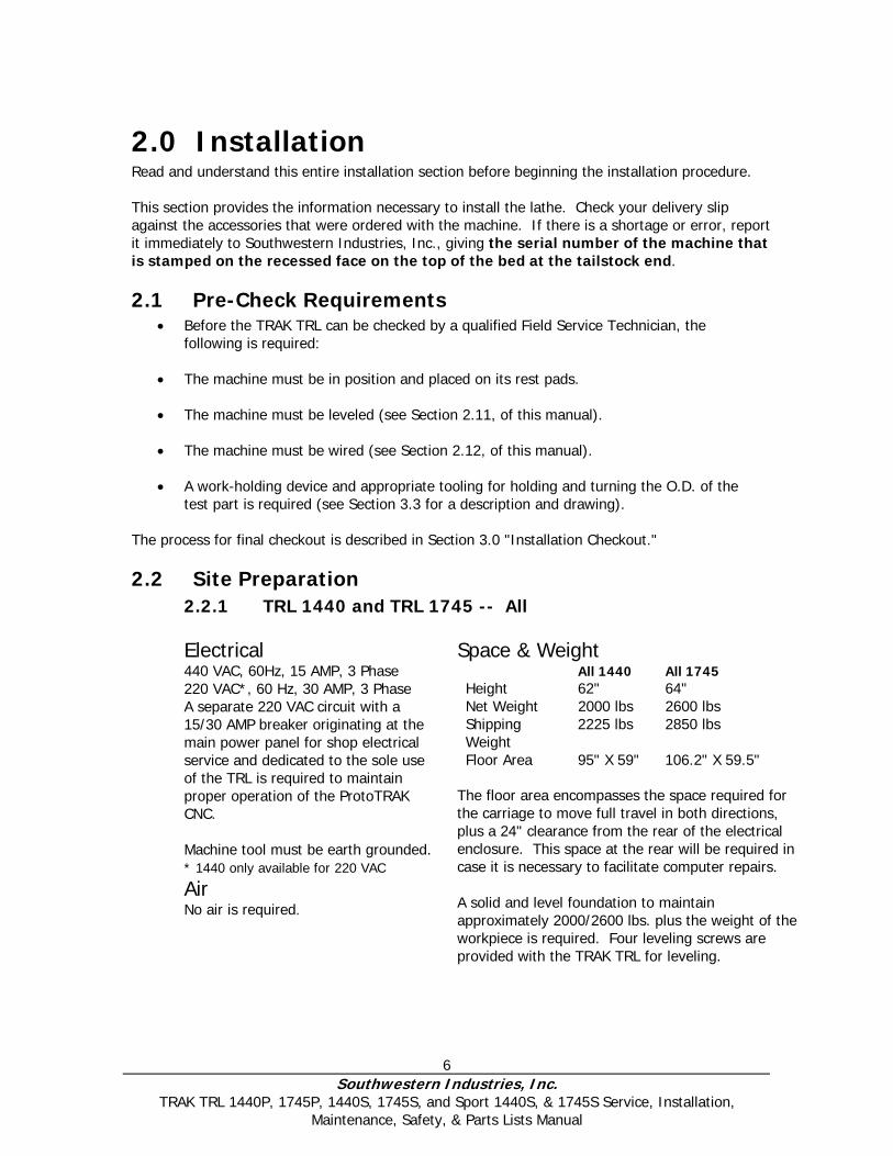
2.2 Site Preparation 2.2.1 TRL 1440 and TRL 1745 -- All Electrical 440 VAC, 60Hz, 15 AMP, 3 Phase 220 VAC*, 60 Hz, 30 AMP, 3 Phase A separate 220 VAC circuit with a 15/30 AMP breaker originating at the main power panel for shop electrical service and dedicated to the sole use of the TRL is required to maintain proper operation of the ProtoTRAK CNC. Machine tool must be earth grounded. * 1440 only available for 220 VAC
Air No air is required.
Space & Weight All 1440 All 1745 Height 62" 64" Net Weight 2000 lbs 2600 lbs Shipping Weight
2225 lbs 2850 lbs
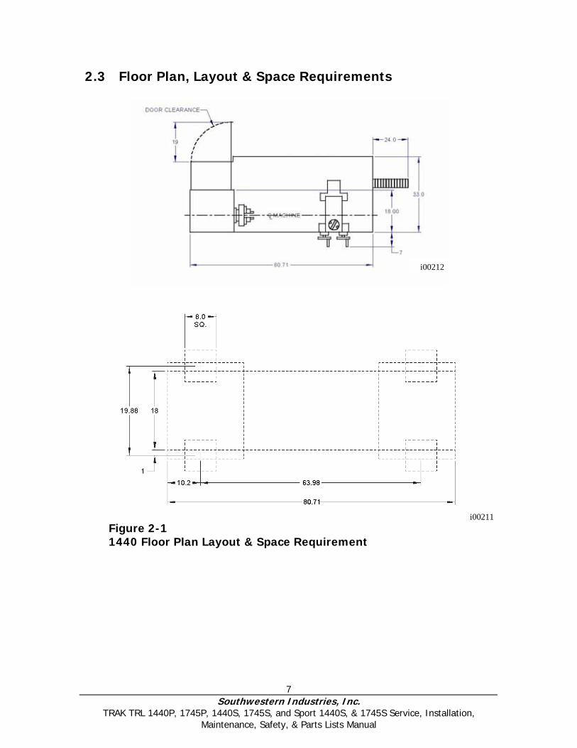
Floor Area 95" X 59" 106.2" X 59.5" The floor area encompasses the space required for the carriage to move full travel in both directions, plus a 24" clearance from the rear of the electrical enclosure. This space at the rear will be required in case it is necessary to facilitate computer repairs. A solid and level foundation to maintain approximately 2000/2600 lbs. plus the weight of the workpiece is required. Four leveling screws are provided with the TRAK TRL for leveling.
7 Southwestern Industries, Inc.
TRAK TRL 1440P, 1745P, 1440S, 1745S, and Sport 1440S, & 1745S Service, Installation, Maintenance, Safety, & Parts Lists Manual
2.3 Floor Plan, Layout & Space Requirements
Figure 2-1 1440 Floor Plan Layout & Space Requirement
i00212
i00211
8 Southwestern Industries, Inc.
TRAK TRL 1440P, 1745P, 1440S, 1745S, and Sport 1440S, & 1745S Service, Installation, Maintenance, Safety, & Parts Lists Manual
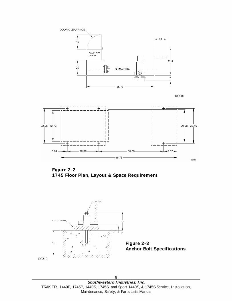
Figure 2-2 1745 Floor Plan, Layout & Space Requirement
Figure 2-3 Anchor Bolt Specifications
i00210
I00081
9 Southwestern Industries, Inc.
TRAK TRL 1440P, 1745P, 1440S, 1745S, and Sport 1440S, & 1745S Service, Installation, Maintenance, Safety, & Parts Lists Manual
2.4 Uncrating Carefully remove the wood crate and protective packaging, paying attention not to scratch, damage, or mar any parts of the machine. Remove the cardboard boxes with the PENDANT DISPLAY (handle carefully). The leveling pads and screws for the machine can be found in the toolbox. Loosen and remove 4 screws and nuts holding the machine to the wood pallet.
ATTENTION! Immediately report, in writing, any damages observed at this time that can be attributed to the
transportation or improper handling/moving of the machine.
2.5 Shortages: Inventory Checklist ______Machine (check model and serial number)
______Leveling pads (B239) and screws (B240) (4 for 1440; and 6 for 1745)
______Pendant Display
______Pendant Cable Cover (22401)
______Carton with various tools
______1440 & 1745 Safety, Operation & Programming Manual
______1440 & 1745 Safety, Installation, Maintenance, Service & Parts List Manual
In case of shortages, contact the representative from whom you purchased the machine.
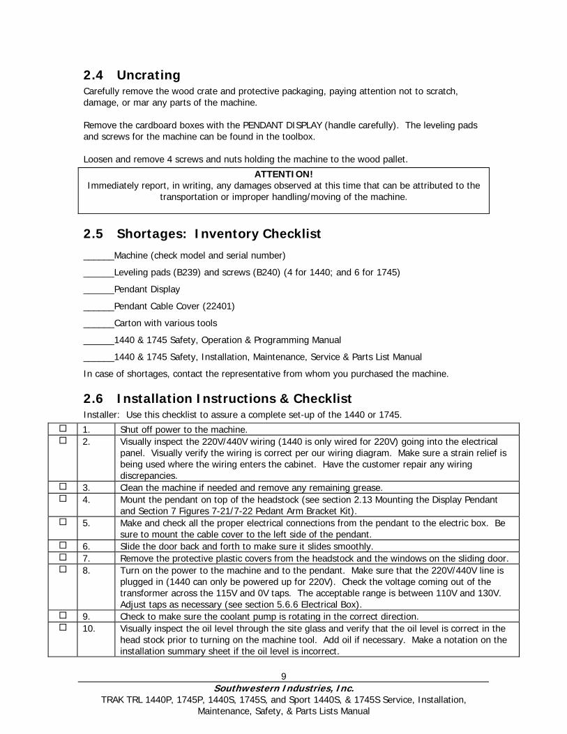
2.6 Installation Instructions & Checklist Installer: Use this checklist to assure a complete set-up of the 1440 or 1745.
1. Shut off power to the machine. 2. Visually inspect the 220V/440V wiring (1440 is only wired for 220V) going into the electrical
panel. Visually verify the wiring is correct per our wiring diagram. Make sure a strain relief is being used where the wiring enters the cabinet. Have the customer repair any wiring discrepancies.
3. Clean the machine if needed and remove any remaining grease. 4. Mount the pendant on top of the headstock (see section 2.13 Mounting the Display Pendant
and Section 7 Figures 7-21/7-22 Pedant Arm Bracket Kit). 5. Make and check all the proper electrical connections from the pendant to the electric box. Be
sure to mount the cable cover to the left side of the pendant. 6. Slide the door back and forth to make sure it slides smoothly. 7. Remove the protective plastic covers from the headstock and the windows on the sliding door. 8. Turn on the power to the machine and to the pendant. Make sure that the 220V/440V line is
plugged in (1440 can only be powered up for 220V). Check the voltage coming out of the transformer across the 115V and 0V taps. The acceptable range is between 110V and 130V. Adjust taps as necessary (see section 5.6.6 Electrical Box).
9. Check to make sure the coolant pump is rotating in the correct direction. 10. Visually inspect the oil level through the site glass and verify that the oil level is correct in the
head stock prior to turning on the machine tool. Add oil if necessary. Make a notation on the installation summary sheet if the oil level is incorrect.
10 Southwestern Industries, Inc.
TRAK TRL 1440P, 1745P, 1440S, 1745S, and Sport 1440S, & 1745S Service, Installation, Maintenance, Safety, & Parts Lists Manual
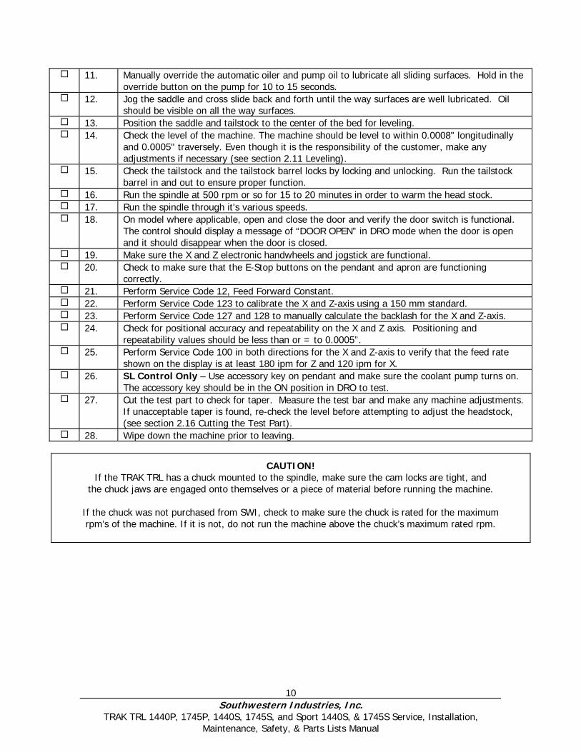
11. Manually override the automatic oiler and pump oil to lubricate all sliding surfaces. Hold in the override button on the pump for 10 to 15 seconds.
12. Jog the saddle and cross slide back and forth until the way surfaces are well lubricated. Oil should be visible on all the way surfaces.
13. Position the saddle and tailstock to the center of the bed for leveling. 14. Check the level of the machine. The machine should be level to within 0.0008" longitudinally
and 0.0005" traversely. Even though it is the responsibility of the customer, make any adjustments if necessary (see section 2.11 Leveling).
15. Check the tailstock and the tailstock barrel locks by locking and unlocking. Run the tailstock barrel in and out to ensure proper function.
16. Run the spindle at 500 rpm or so for 15 to 20 minutes in order to warm the head stock. 17. Run the spindle through it's various speeds. 18. On model where applicable, open and close the door and verify the door switch is functional.
The control should display a message of “DOOR OPEN” in DRO mode when the door is open and it should disappear when the door is closed.
19. Make sure the X and Z electronic handwheels and jogstick are functional. 20. Check to make sure that the E-Stop buttons on the pendant and apron are functioning
correctly. 21. Perform Service Code 12, Feed Forward Constant. 22. Perform Service Code 123 to calibrate the X and Z-axis using a 150 mm standard. 23. Perform Service Code 127 and 128 to manually calculate the backlash for the X and Z-axis. 24. Check for positional accuracy and repeatability on the X and Z axis. Positioning and
repeatability values should be less than or = to 0.0005”. 25. Perform Service Code 100 in both directions for the X and Z-axis to verify that the feed rate
shown on the display is at least 180 ipm for Z and 120 ipm for X. 26. SL Control Only – Use accessory key on pendant and make sure the coolant pump turns on.
The accessory key should be in the ON position in DRO to test. 27. Cut the test part to check for taper. Measure the test bar and make any machine adjustments.
If unacceptable taper is found, re-check the level before attempting to adjust the headstock, (see section 2.16 Cutting the Test Part).
28. Wipe down the machine prior to leaving.
CAUTION! If the TRAK TRL has a chuck mounted to the spindle, make sure the cam locks are tight, and
the chuck jaws are engaged onto themselves or a piece of material before running the machine.
If the chuck was not purchased from SWI, check to make sure the chuck is rated for the maximum rpm’s of the machine. If it is not, do not run the machine above the chuck’s maximum rated rpm.
11 Southwestern Industries, Inc.
TRAK TRL 1440P, 1745P, 1440S, 1745S, and Sport 1440S, & 1745S Service, Installation, Maintenance, Safety, & Parts Lists Manual
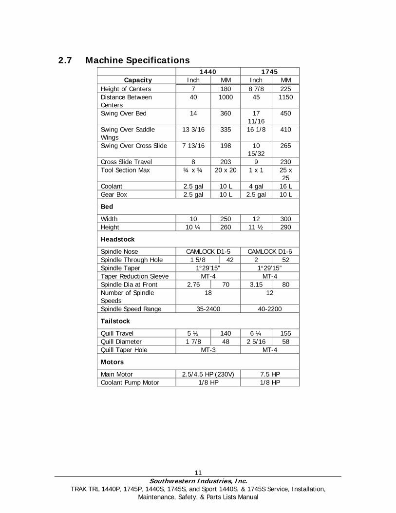
2.7 Machine Specifications 1440 1745
Capacity Inch MM Inch MM Height of Centers 7 180 8 7/8 225 Distance Between Centers
40 1000 45 1150
Swing Over Bed 14 360 17 11/16
450
Swing Over Saddle Wings
13 3/16 335 16 1/8 410
Swing Over Cross Slide 7 13/16 198 10 15/32
265
Cross Slide Travel 8 203 9 230 Tool Section Max ¾ x ¾ 20 x 20 1 x 1 25 x
25 Coolant 2.5 gal 10 L 4 gal 16 L Gear Box 2.5 gal 10 L 2.5 gal 10 L
Bed
Width 10 250 12 300 Height 10 ¼ 260 11 ½ 290
Headstock
Spindle Nose CAMLOCK D1-5 CAMLOCK D1-6 Spindle Through Hole 1 5/8 42 2 52 Spindle Taper 1°29’15” 1°29’15” Taper Reduction Sleeve MT-4 MT-4 Spindle Dia at Front 2.76 70 3.15 80 Number of Spindle Speeds
18 12
Spindle Speed Range 35-2400 40-2200
Tailstock
Quill Travel 5 ½ 140 6 ¼ 155 Quill Diameter 1 7/8 48 2 5/16 58 Quill Taper Hole MT-3 MT-4
Motors
Main Motor 2.5/4.5 HP (230V) 7.5 HP Coolant Pump Motor 1/8 HP 1/8 HP
12 Southwestern Industries, Inc.
TRAK TRL 1440P, 1745P, 1440S, 1745S, and Sport 1440S, & 1745S Service, Installation, Maintenance, Safety, & Parts Lists Manual
2.8 ProtoTRAK SL Control Hardware ProtoTRAK Model LX2 L2 SL 2 -axis CNC, 2-axis DRO 233 PC-based processor D.C. Servo Motors rated at 280 in-oz continuous torque for X and 560 in-oz for the Z axis. Precision ground ballscrews in the carriage and cross-slide to ensure smooth accurate contours without backlash
Feedrate override of programmed feedrate and rapid Polycarbonate sealed membrane and gasket sealed control enclosure to lock out contamination
10 ½" color LCD for clear presentation of prompts, status information, and part graphics RS232 port for interface to computers Modular design simplifies service and maximizes uptime 64 Mb flash drive Optional flash expansion slot Double floppy drive – for system disk and program storage
2.9 Lifting and/or Moving the Machine CAUTION!
The 1440 and 1745 machines weigh approximately 2000 and 2850 lbs. respectively. Proper equipment of sufficient capacity must be used when lifting and/or moving the machine.
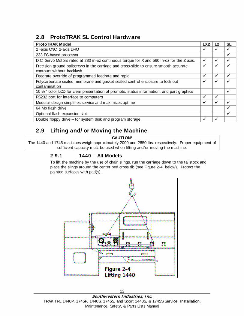
2.9.1 1440 – All Models To lift the machine by the use of chain slings, run the carriage down to the tailstock and place the slings around the center bed cross rib (see Figure 2-4, below). Protect the painted surfaces with pad(s).
13 Southwestern Industries, Inc.
TRAK TRL 1440P, 1745P, 1440S, 1745S, and Sport 1440S, & 1745S Service, Installation, Maintenance, Safety, & Parts Lists Manual
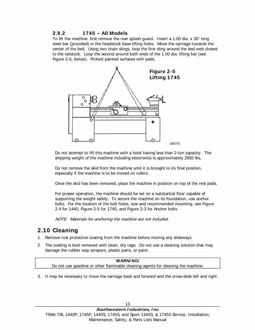
2.9.2 1745 – All Models To lift the machine, first remove the rear splash guard. Insert a 1.00 dia. x 36” long steel bar (provided) in the headstock base lifting holes. Move the carriage towards the center of the bed. Using two chain slings, loop the first sling around the bed web closest to the tailstock. Loop the second around both ends of the 1.00 dia. lifting bar (see Figure 2-5, below). Protect painted surfaces with pads.
Do not attempt to lift this machine with a hoist having less than 2-ton capacity. The shipping weight of the machine including electronics is approximately 2850 lbs.
Do not remove the skid from the machine until it is brought to its final position, especially if the machine is to be moved on rollers.
Once the skid has been removed, place the machine in position on top of the rest pads.
For proper operation, the machine should be set on a substantial floor capable of supporting the weight safely. To secure the machine on its foundation, use anchor bolts. For the location of the bolt holes, size and recommended mounting, see Figure 2-4 for 1440, Figure 2-5 for 1745, and Figure 2-3 for Anchor bolts.
NOTE: Materials for anchoring the machine are not included.
2.10 Cleaning 1. Remove rust protective coating from the machine before moving any slideways
2. The coating is best removed with clean, dry rags. Do not use a cleaning solution that may damage the rubber way scrapers, plastic parts, or paint.
WARNING! Do not use gasoline or other flammable cleaning agents for cleaning the machine.
3. It may be necessary to move the carriage back and forward and the cross-slide left and right.
Figure 2-5 Lifting 1745
i00191
14 Southwestern Industries, Inc.
TRAK TRL 1440P, 1745P, 1440S, 1745S, and Sport 1440S, & 1745S Service, Installation, Maintenance, Safety, & Parts Lists Manual
CAUTION! Never move any of the above parts over ways that were not previously cleaned. Serious
damage to the TURCITE surface of slideways can occur.
4. Be certain the carriage, cross slide and spindle move freely and smoothly over their entire length.
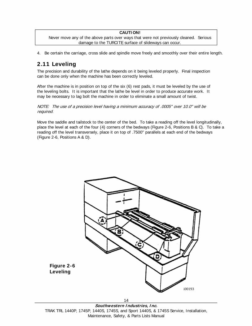
2.11 Leveling The precision and durability of the lathe depends on it being leveled properly. Final inspection can be done only when the machine has been correctly leveled. After the machine is in position on top of the six (6) rest pads, it must be leveled by the use of the leveling bolts. It is important that the lathe be level in order to produce accurate work. It may be necessary to lag bolt the machine in order to eliminate a small amount of twist. NOTE: The use of a precision level having a minimum accuracy of .0005" over 10.0" will be required. Move the saddle and tailstock to the center of the bed. To take a reading off the level longitudinally, place the level at each of the four (4) corners of the bedways (Figure 2-6, Positions B & C). To take a reading off the level transversely, place it on top of .7500" parallels at each end of the bedways (Figure 2-6, Positions A & D).
Figure 2-6 Leveling
i00193
15 Southwestern Industries, Inc.
TRAK TRL 1440P, 1745P, 1440S, 1745S, and Sport 1440S, & 1745S Service, Installation, Maintenance, Safety, & Parts Lists Manual
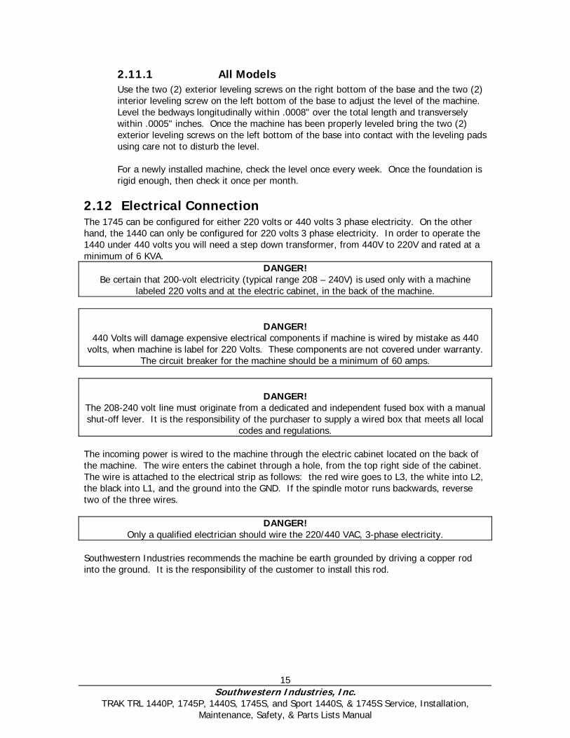
2.11.1 All Models Use the two (2) exterior leveling screws on the right bottom of the base and the two (2) interior leveling screw on the left bottom of the base to adjust the level of the machine. Level the bedways longitudinally within .0008" over the total length and transversely within .0005" inches. Once the machine has been properly leveled bring the two (2) exterior leveling screws on the left bottom of the base into contact with the leveling pads using care not to disturb the level. For a newly installed machine, check the level once every week. Once the foundation is rigid enough, then check it once per month.
2.12 Electrical Connection The 1745 can be configured for either 220 volts or 440 volts 3 phase electricity. On the other hand, the 1440 can only be configured for 220 volts 3 phase electricity. In order to operate the 1440 under 440 volts you will need a step down transformer, from 440V to 220V and rated at a minimum of 6 KVA.
DANGER! Be certain that 200-volt electricity (typical range 208 – 240V) is used only with a machine
labeled 220 volts and at the electric cabinet, in the back of the machine.
DANGER! 440 Volts will damage expensive electrical components if machine is wired by mistake as 440
volts, when machine is label for 220 Volts. These components are not covered under warranty. The circuit breaker for the machine should be a minimum of 60 amps.
DANGER! The 208-240 volt line must originate from a dedicated and independent fused box with a manual shut-off lever. It is the responsibility of the purchaser to supply a wired box that meets all local
codes and regulations. The incoming power is wired to the machine through the electric cabinet located on the back of the machine. The wire enters the cabinet through a hole, from the top right side of the cabinet. The wire is attached to the electrical strip as follows: the red wire goes to L3, the white into L2, the black into L1, and the ground into the GND. If the spindle motor runs backwards, reverse two of the three wires.
DANGER!
Only a qualified electrician should wire the 220/440 VAC, 3-phase electricity. Southwestern Industries recommends the machine be earth grounded by driving a copper rod into the ground. It is the responsibility of the customer to install this rod.

16 Southwestern Industries, Inc.
TRAK TRL 1440P, 1745P, 1440S, 1745S, and Sport 1440S, & 1745S Service, Installation, Maintenance, Safety, & Parts Lists Manual
Fig
ure
2-7
1
44
0 E
lect
rica
l Sch
emat
ic
17 Southwestern Industries, Inc.
TRAK TRL 1440P, 1745P, 1440S, 1745S, and Sport 1440S, & 1745S Service, Installation, Maintenance, Safety, & Parts Lists Manual
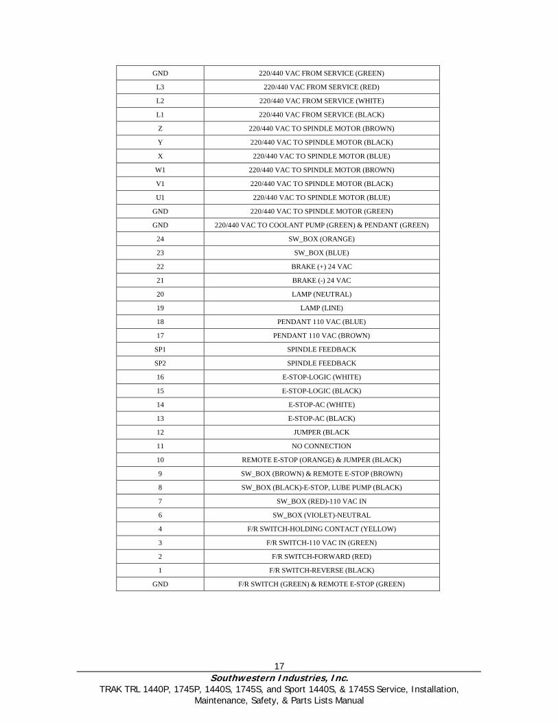
GND 220/440 VAC FROM SERVICE (GREEN)
L3 220/440 VAC FROM SERVICE (RED)
L2 220/440 VAC FROM SERVICE (WHITE)
L1 220/440 VAC FROM SERVICE (BLACK)
Z 220/440 VAC TO SPINDLE MOTOR (BROWN)
Y 220/440 VAC TO SPINDLE MOTOR (BLACK)
X 220/440 VAC TO SPINDLE MOTOR (BLUE)
W1 220/440 VAC TO SPINDLE MOTOR (BROWN)
V1 220/440 VAC TO SPINDLE MOTOR (BLACK)
U1 220/440 VAC TO SPINDLE MOTOR (BLUE)
GND 220/440 VAC TO SPINDLE MOTOR (GREEN)
GND 220/440 VAC TO COOLANT PUMP (GREEN) & PENDANT (GREEN)
24 SW_BOX (ORANGE)
23 SW_BOX (BLUE)
22 BRAKE (+) 24 VAC
21 BRAKE (-) 24 VAC
20 LAMP (NEUTRAL)
19 LAMP (LINE)
18 PENDANT 110 VAC (BLUE)
17 PENDANT 110 VAC (BROWN)
SP1 SPINDLE FEEDBACK
SP2 SPINDLE FEEDBACK
16 E-STOP-LOGIC (WHITE)
15 E-STOP-LOGIC (BLACK)
14 E-STOP-AC (WHITE)
13 E-STOP-AC (BLACK)
12 JUMPER (BLACK
11 NO CONNECTION
10 REMOTE E-STOP (ORANGE) & JUMPER (BLACK)
9 SW_BOX (BROWN) & REMOTE E-STOP (BROWN)
8 SW_BOX (BLACK)-E-STOP, LUBE PUMP (BLACK)
7 SW_BOX (RED)-110 VAC IN
6 SW_BOX (VIOLET)-NEUTRAL
4 F/R SWITCH-HOLDING CONTACT (YELLOW)
3 F/R SWITCH-110 VAC IN (GREEN)
2 F/R SWITCH-FORWARD (RED)
1 F/R SWITCH-REVERSE (BLACK)
GND F/R SWITCH (GREEN) & REMOTE E-STOP (GREEN)
18 Southwestern Industries, Inc.
TRAK TRL 1440P, 1745P, 1440S, 1745S, and Sport 1440S, & 1745S Service, Installation, Maintenance, Safety, & Parts Lists Manual
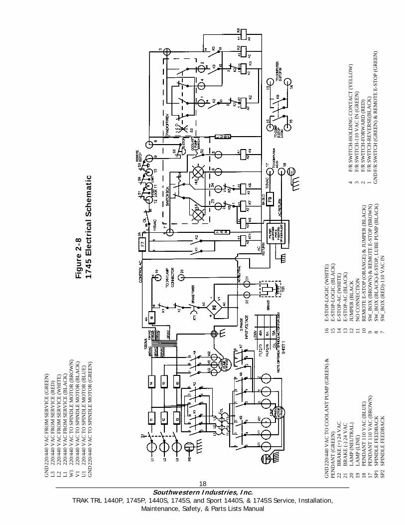
Fig
ure
2-8
1
74
5 E
lect
rica
l Sch
emat
ic
GN
D 22
0/44
0 V
AC
FR
OM
SER
VIC
E (G
REE
N)
L3
220/
440
VA
C F
RO
M S
ERV
ICE
(RED
) L2
22
0/44
0 V
AC
FR
OM
SER
VIC
E (W
HIT
E)
L1
220/
440
VA
C F
RO
M S
ERV
ICE
(BLA
CK
) W
1 22
0/44
0 V
AC
TO
SPI
ND
LE M
OTO
R (B
RO
WN
) V
1 22
0/44
0 V
AC
TO
SPI
ND
LE M
OTO
R (B
LAC
K)
U1
220/
440
VA
C T
O S
PIN
DLE
MO
TOR
(BLU
E)
GN
D 22
0/44
0 V
AC
TO
SPI
ND
LE M
OTO
R (G
REE
N)
GN
D 22
0/44
0 V
AC
TO
CO
OLA
NT
PUM
P (G
REE
N) &
PE
ND
AN
T (G
REE
N)
22
BR
AK
E (+
) 24
VA
C
21
BR
AK
E (-
) 24
VA
C
20
LAM
P (N
EUTR
AL)
19
LA
MP
(LIN
E)
18
PEN
DA
NT
110
VA
C (B
LUE)
17
PE
ND
AN
T 11
0 V
AC
(BR
OW
N)
SP1
SPIN
DLE
FEE
DB
AC
K
SP2
SPIN
DLE
FEE
DB
AC
K
16
E-ST
OP-
LOG
IC (W
HIT
E)
15
E-ST
OP-
LOG
IC (B
LAC
K)
14
E-ST
OP-
AC
(WH
ITE)
13
E-
STO
P-A
C (B
LAC
K)
12
JUM
PER
(BLA
CK
11
N
O C
ON
NEC
TIO
N
10
REM
OTE
E-S
TOP
(OR
AN
GE)
& JU
MPE
R (B
LAC
K)
9 SW
_BO
X (B
RO
WN
) & R
EMO
TE E
-STO
P (B
RO
WN
) 8
SW_B
OX
(BLA
CK
)-E-
STO
P, L
UB
E PU
MP
(BLA
CK
) 7
SW_B
OX
(RED
)-11
0 V
AC
IN
4 F/
R S
WIT
CH
-HO
LDIN
G C
ON
TAC
T (Y
ELLO
W)
3 F/
R S
WIT
CH
-110
VA
C IN
(GR
EEN
) 2
F/R
SW
ITC
H-F
OR
WA
RD
(RED
) 1
F/R
SW
ITC
H-R
EVER
SE(B
LAC
K)
GN
D F
/R S
WIT
CH
(GR
EEN
) & R
EMO
TE E
-STO
P (G
REE
N)
19 Southwestern Industries, Inc.
TRAK TRL 1440P, 1745P, 1440S, 1745S, and Sport 1440S, & 1745S Service, Installation, Maintenance, Safety, & Parts Lists Manual
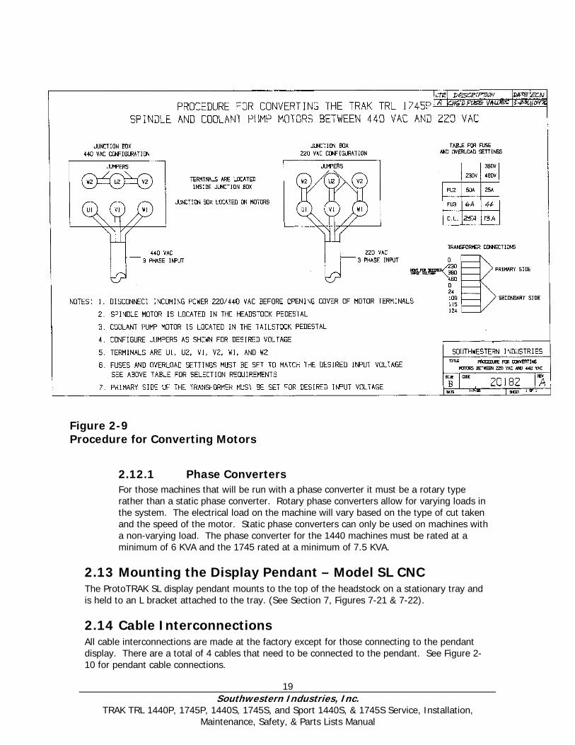
2.12.1 Phase Converters For those machines that will be run with a phase converter it must be a rotary type rather than a static phase converter. Rotary phase converters allow for varying loads in the system. The electrical load on the machine will vary based on the type of cut taken and the speed of the motor. Static phase converters can only be used on machines with a non-varying load. The phase converter for the 1440 machines must be rated at a minimum of 6 KVA and the 1745 rated at a minimum of 7.5 KVA.
2.13 Mounting the Display Pendant – Model SL CNC The ProtoTRAK SL display pendant mounts to the top of the headstock on a stationary tray and is held to an L bracket attached to the tray. (See Section 7, Figures 7-21 & 7-22).
2.14 Cable Interconnections All cable interconnections are made at the factory except for those connecting to the pendant display. There are a total of 4 cables that need to be connected to the pendant. See Figure 2-10 for pendant cable connections.
Figure 2-9 Procedure for Converting Motors

20 Southwestern Industries, Inc.
TRAK TRL 1440P, 1745P, 1440S, 1745S, and Sport 1440S, & 1745S Service, Installation, Maintenance, Safety, & Parts Lists Manual
With the main power to the machine turned off plug in the connectors that are bundled on the side of the machine. Each cable mates to only one connector on the pendant display, on the left side of the pendant. Use the key on the pendant to match up the connectors with the correct port. The parallel port will have a key plugged into this port. The monitor port, RS232 and network ports will be left empty during installation. The machine ID key plugs into the LPT port. Make sure there is a hardware (option) key plugged into the parallel port of the pendant. This key activates any converters or options ordered. The part number for this key is 22648. The key must be programmed according to the type of machine it is on and the options ordered.
CAUTION! Make sure the main power switch is turned off on the back of the electrical cabinet before
plugging in the cables.
2.15 Lubrication System
2.15.1 Headstock An automatic splash type of lubrication provides an even distribution of oil to all the gears and bearings in the headstock. To fill the headstock reservoir to the recommended level, remove the oil cap on top of the headstock cover. Through the hole fill the reservoir to the center of the oil sight gage, located on the front of the machine beneath the speed select lever. Mobile DTE 24 or equivalent should be used.
The headstock gearbox oil must be drained and flushed after the first 150 hours of operation. A small percentage of kerosene may be added to the gearbox to flush out dirt and sediment. Operate the machine for several minutes without load so that the flushing oil can circulate through the reservoir and remove the dirt. The flushing oil must then be drained and new oil added. Do not flush with solvents that will soften the paint. Thereafter, the oil should be flushed and drained every 1000 hours of operation.
2.15.2 Automatic Lubrication Pump The auto lube system provides centralized automatic lubrication for the cross slide, saddle and ball screws. Flow is proportioned to each lubrication point with appropriately sized orifices. The lube pump’s 2 liter reservoir is serviced with SAE 30 weight oil or Mobile Vactra Oil #2. The pump’s output can be regulated through a series of DIP switches that control the pause time between pumping cycles, and the duration of the pumping cycle as shown below. Switches are located under the pump control cover.
Pause Time Pump Time 1 = 2.5 min. 1 = 2.5 sec. 2 = 5 min. 2 = 5 sec. 3 = 10 min. 3 = 10 sec. 4 = 20 min. 4 = 20 sec. 5 = 40 min. 6 = 80 min.
21 Southwestern Industries, Inc.
TRAK TRL 1440P, 1745P, 1440S, 1745S, and Sport 1440S, & 1745S Service, Installation, Maintenance, Safety, & Parts Lists Manual
If two or more of the switches are in the “ON” position, the time is additive.
Pause Time Example: 52.5 min. = switch 1 + 3 + 5 LED’s on the pumps’ control indicate operating conditions as shown below:
GREEN = power on YELLOW = pump operating RED = warning; out of oil
The pump may also be operated manually with a push button located on the pumps’ control panel.
2.15.3 Tailstock The spindle and screw are lubricated by 4 oilers located on top of the spindle housing. The tailstock lock is lubricated with one oiler located on the front face. The bedways on which the tailstock slides should be cleaned and oiled frequently.
2.15.4 Miscellaneous Information For all oilers on the machine, use a medium SAE No. 30 machine oil or Mobile Vactra Oil #2. Before filling reservoirs or oil cups, always wipe off with a clean rag any accumulation of old oil, grease or dirt that might get into a part being lubricated.
2.15.5 Caution Do not mix detergent type automotive oil, or multi-purpose oils with the regular grade of SAE No. 30 lubricating oil.

22 Southwestern Industries, Inc.
TRAK TRL 1440P, 1745P, 1440S, 1745S, and Sport 1440S, & 1745S Service, Installation, Maintenance, Safety, & Parts Lists Manual
Figure 2-10 SL Pendant Cable Connections, Left Side
23 Southwestern Industries, Inc.
TRAK TRL 1440P, 1745P, 1440S, 1745S, and Sport 1440S, & 1745S Service, Installation, Maintenance, Safety, & Parts Lists Manual
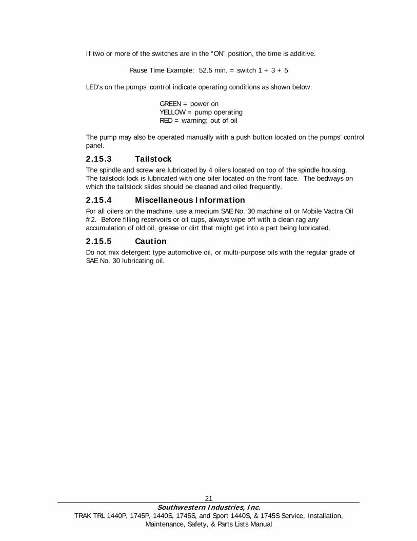
Figure 2-11 SL Pendant, Right Side

24 Southwestern Industries, Inc.
TRAK TRL 1440P, 1745P, 1440S, 1745S, and Sport 1440S, & 1745S Service, Installation, Maintenance, Safety, & Parts Lists Manual
Figure 2-12 ProtoTRAK L2 Pendant & Switch Box
i002
31
25 Southwestern Industries, Inc.
TRAK TRL 1440P, 1745P, 1440S, 1745S, and Sport 1440S, & 1745S Service, Installation, Maintenance, Safety, & Parts Lists Manual
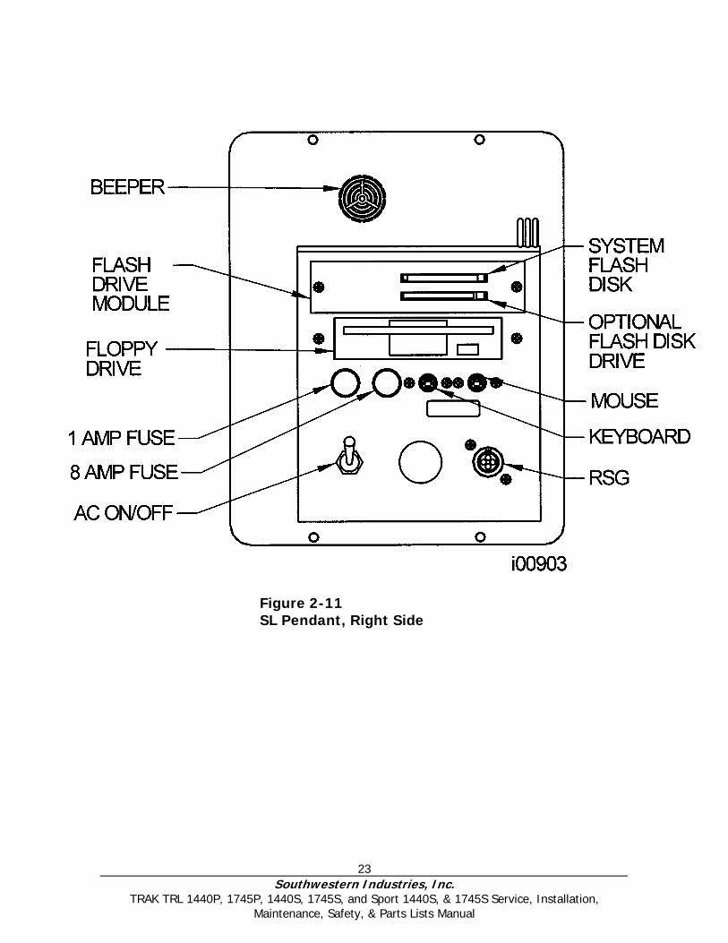
Figure 2-13 L2 Pendant Back
i001
42
26 Southwestern Industries, Inc.
TRAK TRL 1440P, 1745P, 1440S, 1745S, and Sport 1440S, & 1745S Service, Installation, Maintenance, Safety, & Parts Lists Manual
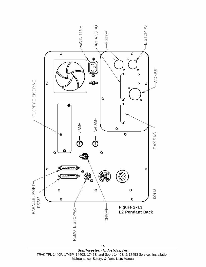
Figure 2-14 L2 Connection Box
i002
40
27 Southwestern Industries, Inc.
TRAK TRL 1440P, 1745P, 1440S, 1745S, and Sport 1440S, & 1745S Service, Installation, Maintenance, Safety, & Parts Lists Manual
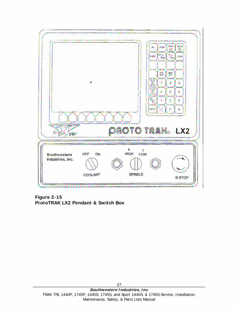
Figure 2-15 ProtoTRAK LX2 Pendant & Switch Box
28 Southwestern Industries, Inc.
TRAK TRL 1440P, 1745P, 1440S, 1745S, and Sport 1440S, & 1745S Service, Installation, Maintenance, Safety, & Parts Lists Manual
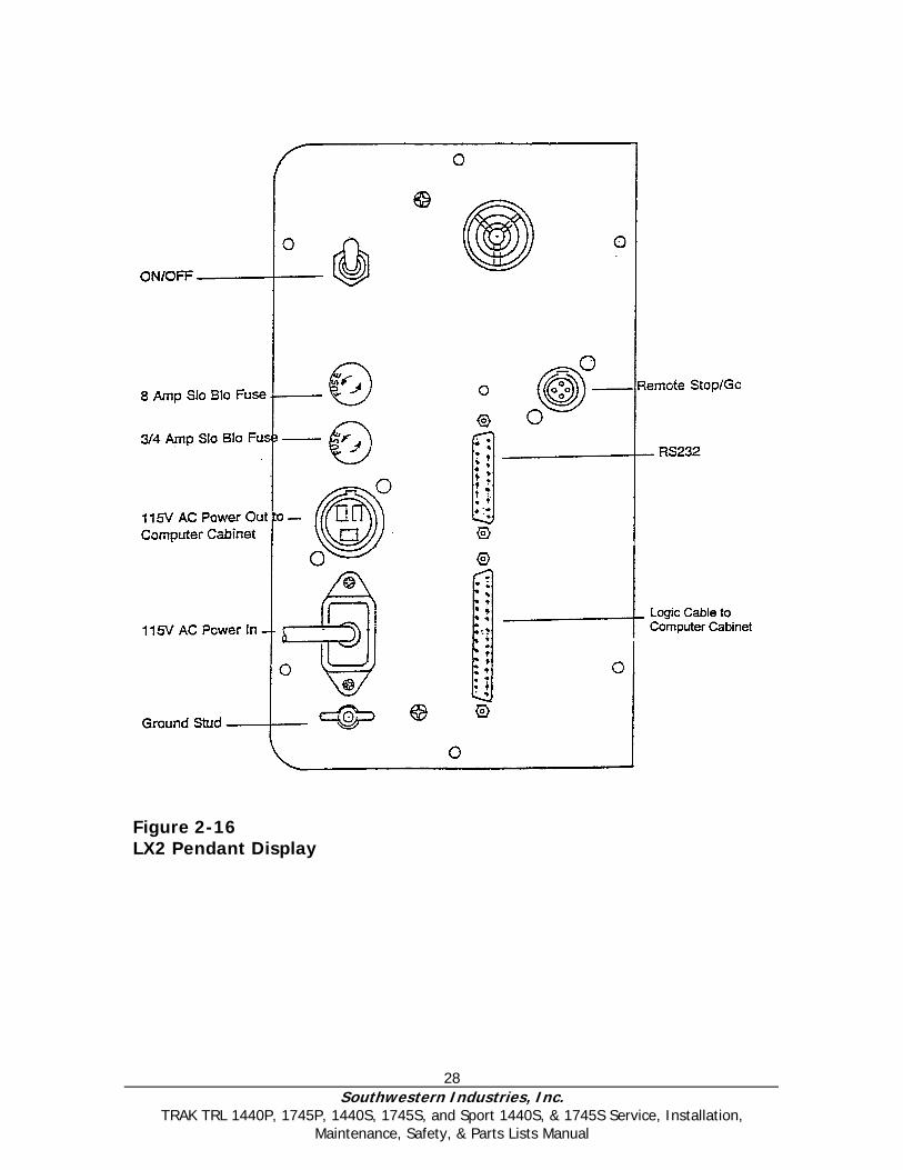
Figure 2-16 LX2 Pendant Display
29 Southwestern Industries, Inc.
TRAK TRL 1440P, 1745P, 1440S, 1745S, and Sport 1440S, & 1745S Service, Installation, Maintenance, Safety, & Parts Lists Manual
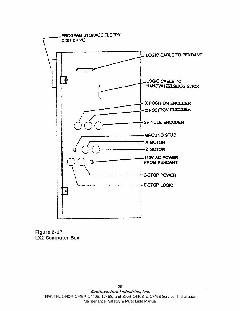
Figure 2-17 LX2 Computer Box
30 Southwestern Industries, Inc.
TRAK TRL 1440P, 1745P, 1440S, 1745S, and Sport 1440S, & 1745S Service, Installation, Maintenance, Safety, & Parts Lists Manual
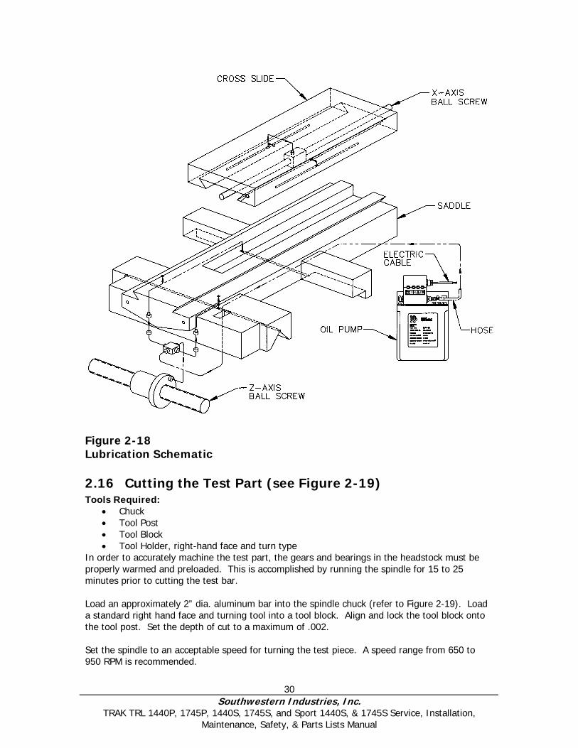
Figure 2-18 Lubrication Schematic
2.16 Cutting the Test Part (see Figure 2-19) Tools Required:
• Chuck • Tool Post • Tool Block • Tool Holder, right-hand face and turn type
In order to accurately machine the test part, the gears and bearings in the headstock must be properly warmed and preloaded. This is accomplished by running the spindle for 15 to 25 minutes prior to cutting the test bar. Load an approximately 2” dia. aluminum bar into the spindle chuck (refer to Figure 2-19). Load a standard right hand face and turning tool into a tool block. Align and lock the tool block onto the tool post. Set the depth of cut to a maximum of .002. Set the spindle to an acceptable speed for turning the test piece. A speed range from 650 to 950 RPM is recommended.

31 Southwestern Industries, Inc.
TRAK TRL 1440P, 1745P, 1440S, 1745S, and Sport 1440S, & 1745S Service, Installation, Maintenance, Safety, & Parts Lists Manual
3.0 Installation Checkout This procedure will be performed by an SWI Field Service Technician or the Service Representative of an Authorized TRAK or Sport Distributor. Before checkout procedures may be performed, it is necessary for the machine to have been installed and tooling provided. See Section 2.0 for machine set-up.
3.1 Visual Inspection • Check if the display pendant has been installed (see Figures 2-10 through 2-17
for reference to display and computer module interconnections).
• Check if the lathe is leveled (see Section 2.11).
• Check if loose parts, keys or jaws will be thrown from the chuck if it is turned on.
DANGER
Before operating the lathe, verify that the chuck maximum safe operating speed is rated by the manufacturer at a
minimum of 2400 rpm.
• Check if the oil reservoirs in the head and the lube pump are filled and pump oil to the ways.
• Check if the chuck guard is in place.
• Check if 220 volt power is connected by switching on the master 200 volt switch on the back of the lathe and then switching on the spindle (generally, forward = the chuck rotating counterclockwise when facing it).
• Switch on the pendant display, enter Set Up Mode, and enter Service Code 133
(see operation manual for detailed instructions). Engage the spindle encoder drive, rotate the chuck manually and check if the Z axis reads. If it reads, this will indicate that the spindle encoder is functioning.
3.2 Inspection of DRO Operation Turn on the ProtoTRAK LX2 or L2 display and enter the DRO Mode.
• Check if X and Z handwheels move each axis in both directions in DRO mode.
• Check if the jogstick moves each axis in both directions in DRO mode.
• Check if the emergency stop button stops the spindle and disables the X and Z handwheels.

32 Southwestern Industries, Inc.
TRAK TRL 1440P, 1745P, 1440S, 1745S, and Sport 1440S, & 1745S Service, Installation, Maintenance, Safety, & Parts Lists Manual
3.3 Cutting the Test Part (See Figure 3-1) TOOLS REQUIRED:
• Tool Post • Tool Block • Tool Holder, right-hand face and turn type
In order to accurately machine the test part, the gears and bearings in the headstock must be properly warmed and preloaded. This is accomplished by running the spindle for 15 to 25 minutes prior to cutting the test bar. Load an approximately 2” dia. aluminum bar into the spindle chuck (refer to Figure 3-1). Load a standard right hand face and turning tool into a toolblock. Align and lock the toolblock onto the tool post. Set the depth of cut to a maximum of .005. Set the spindle to an acceptable speed for turning the test piece. A speed range from 425 to 950 R.P.M. is recommended.
3.4 Measurement of the Test Part TOOL REQUIRED:
• O.D. Micrometers with .0001" graduations Using a calibrated O.D. micrometer with .0001" graduations, measure and record the generated dimension at a 6.00 spacing. The acceptable measurement of parallelism of spindle axis to carriage movement (taper of test piece) is .0008" in 6". If the taper measured is not acceptable, re-machine the test part and/or check and adjust the level of the machine, or adjust the headstock per Section 6.1.26.
Figure 3-1 Measuring Test Part
33 Southwestern Industries, Inc.
TRAK TRL 1440P, 1745P, 1440S, 1745S, and Sport 1440S, & 1745S Service, Installation, Maintenance, Safety, & Parts Lists Manual
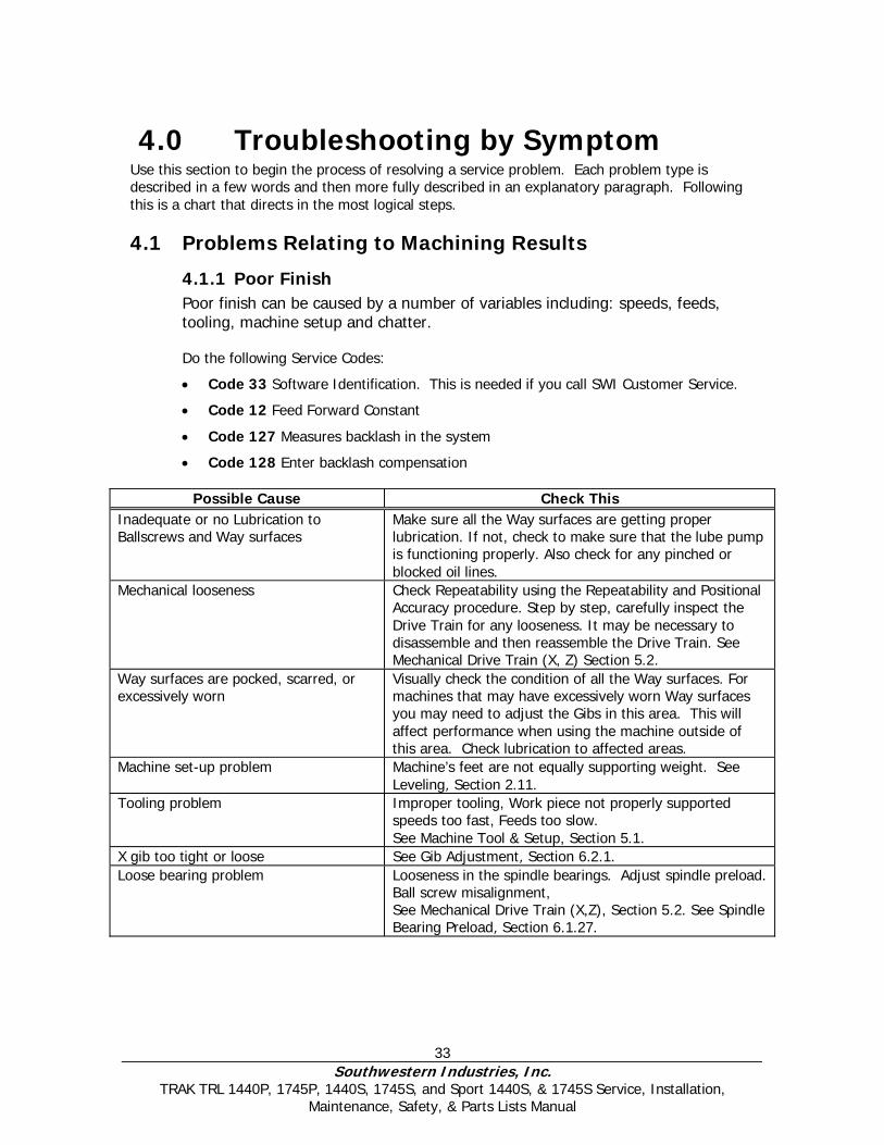
4.0 Troubleshooting by Symptom Use this section to begin the process of resolving a service problem. Each problem type is described in a few words and then more fully described in an explanatory paragraph. Following this is a chart that directs in the most logical steps.
4.1 Problems Relating to Machining Results
4.1.1 Poor Finish Poor finish can be caused by a number of variables including: speeds, feeds, tooling, machine setup and chatter. Do the following Service Codes:
• Code 33 Software Identification. This is needed if you call SWI Customer Service.
• Code 12 Feed Forward Constant
• Code 127 Measures backlash in the system
• Code 128 Enter backlash compensation
Possible Cause Check This Inadequate or no Lubrication to Ballscrews and Way surfaces
Make sure all the Way surfaces are getting proper lubrication. If not, check to make sure that the lube pump is functioning properly. Also check for any pinched or blocked oil lines.
Mechanical looseness Check Repeatability using the Repeatability and Positional Accuracy procedure. Step by step, carefully inspect the Drive Train for any looseness. It may be necessary to disassemble and then reassemble the Drive Train. See Mechanical Drive Train (X, Z) Section 5.2.
Way surfaces are pocked, scarred, or excessively worn
Visually check the condition of all the Way surfaces. For machines that may have excessively worn Way surfaces you may need to adjust the Gibs in this area. This will affect performance when using the machine outside of this area. Check lubrication to affected areas.
Machine set-up problem Machine’s feet are not equally supporting weight. See Leveling, Section 2.11.
Tooling problem Improper tooling, Work piece not properly supported speeds too fast, Feeds too slow. See Machine Tool & Setup, Section 5.1.
X gib too tight or loose See Gib Adjustment, Section 6.2.1. Loose bearing problem Looseness in the spindle bearings. Adjust spindle preload.
Ball screw misalignment, See Mechanical Drive Train (X,Z), Section 5.2. See Spindle Bearing Preload, Section 6.1.27.

Southwestern Industries, Inc.
TRAK TRL 1440P, 1745P, 1440S, 1745S, and Sport 1440S, & 1745S Service, Installation, Maintenance, Safety, & Parts Lists Manual
34
4.1.2 Turning Diameters Out of Round
Parts are not round within .0006” TIR for 1440 and 1745. This is best measured by using a .0001” dial indicator and mounting to the inside taper of the spindle. Rotate the spindle and measure the indicator movement.
Do the following service code and procedures: Possible Cause Check This
Tooling problem Improper tooling, workpiece not properly supported. See Machine Tool & Setup, Section 5.1.
Loose bearing problem Looseness in the spindle bearings. See Mechanical Drive Train (X, Z), Section 5.2. Spindle bearing not preloaded correctly. Reseat bearing and preload. See Spindle Bearing Preload, Section 6.1.27.
4.1.3 Cutting Taper Parts are considered to be cutting on a taper if there is a difference in diameter of more than .0008” over 6 inches. This is best measured by using a .0001” micrometer.
Do the following service code and procedures:
• Code 12 Determines the feed forward constant for the axis motors.
Possible Cause Check This Machine set-up problem Machine not leveled properly
See Leveling - Section 2.11. Tooling problem Improper tooling; Work piece not properly supported. Use steady rest or
follow rest, reduce overhang from chuck headstock or tailstock. Looseness in the gib or misalignment of ball screw
Gib adjustment. See Gib Adjustment - Section 6.2.1. See Z Ball screw Alignment - Section 6.1.25.
Loose bearing problem Looseness in the spindle bearings. See Mechanical Drive Train (X,Z) - 5.2. See Spindle Bearing Preload - Section 6.1.27.
Headstock and/or tailstock not aligned
See Adjust Headstock for Taper - Section 6.1.26. To adjust tailstock from side to side, adjust gib screw. See Aligning Tailstock to Spindle Section 6.1.28.
4.1.4 Parts Have Incorrect Dimensions Parts are being machined with dimensions that are different than those programmed. Typical accuracy expectations should be:
• Parts should be round within .0006” TIR on both the 1440 and 1745. • The acceptable measurement of parallelism of spindle axis to carriage movement is
.0008” over 6 inches.
Southwestern Industries, Inc.
TRAK TRL 1440P, 1745P, 1440S, 1745S, and Sport 1440S, & 1745S Service, Installation, Maintenance, Safety, & Parts Lists Manual
35
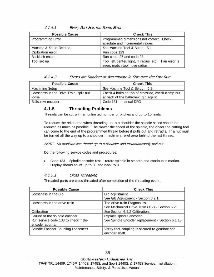
4.1.4.1 Every Part Has the Same Error
Possible Cause Check This Programming Error Programmed dimensions not correct. Check
absolute and incremental values. Machine & Setup Related See Machine Tool & Setup - 5.1. Calibration error Run code 123 Backlash error Run code 27 and code 28 Tool set up Tool left/center/right, T radius, etc. If an error is
seen, match tool nose radius.
4.1.4.2 Errors are Random or Accumulate in Size over the Part Run
Possible Cause Check This Machining Setup See Machine Tool & Setup – 5.2. Looseness in the Drive Train, split nut loose
Check 4 bolts on top of crosslide, check clamp nut at back of the ballscrew, gib adjust.
Ballscrew encoder Code 131 – manual DRO
4.1.5 Threading Problems Threads can be cut with an unlimited number of pitches and up to 10 leads.
To reduce the relief area when threading up to a shoulder the spindle speed should be reduced as much as possible. The slower the speed of the spindle, the closer the cutting tool can come to the end of the programmed thread before it pulls out and retracts. If a nut must be turned all the way up to a shoulder, machine a relief area behind the last thread.
NOTE: No machine can thread up to a shoulder and instantaneously pull out.
Do the following service codes and procedures:
• Code 133 Spindle encoder test – rotate spindle in smooth and continuous motion. Display should count up to 36 and back to 0.
4.1.5.1 Cross Threading
Threaded parts are cross-threaded after completion of the threading event.
Possible Cause Check This Looseness in the Gib Gib adjustment
See Gib Adjustment - Section 6.2.1. Looseness in the drive train The drive train Diagnostics
See Mechanical Drive Train (X,Z) - Section 5.2. Calibration See Section 6.2.2 Calibration. Failure of the spindle encoder Run service code 133 to check if the encoder counts.
Replace spindle encoder See Spindle Encoder replacement - Section 6.1.13.
Spindle Encoder Coupling Looseness Verify that coupling is secured to gearbox and encoder shaft.
Southwestern Industries, Inc.
TRAK TRL 1440P, 1745P, 1440S, 1745S, and Sport 1440S, & 1745S Service, Installation, Maintenance, Safety, & Parts Lists Manual
36
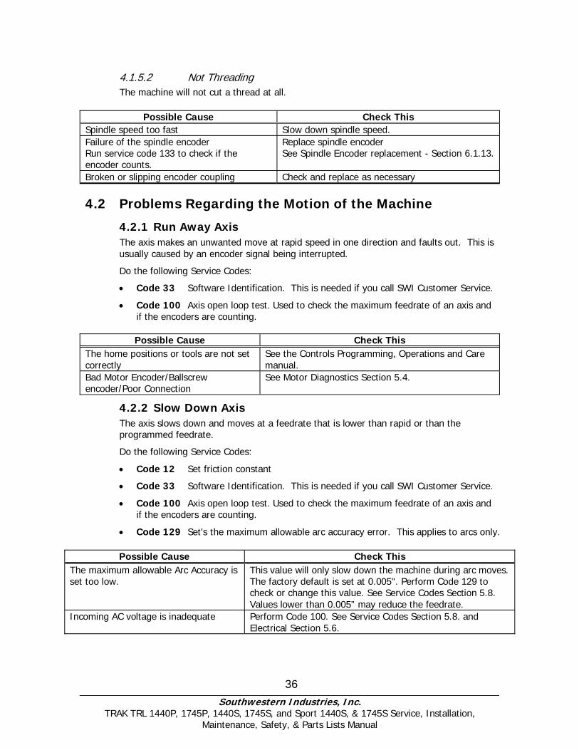
4.1.5.2 Not Threading The machine will not cut a thread at all.
Possible Cause Check This Spindle speed too fast Slow down spindle speed. Failure of the spindle encoder Run service code 133 to check if the encoder counts.
Replace spindle encoder See Spindle Encoder replacement - Section 6.1.13.
Broken or slipping encoder coupling Check and replace as necessary
4.2 Problems Regarding the Motion of the Machine
4.2.1 Run Away Axis The axis makes an unwanted move at rapid speed in one direction and faults out. This is usually caused by an encoder signal being interrupted.
Do the following Service Codes:
• Code 33 Software Identification. This is needed if you call SWI Customer Service.
• Code 100 Axis open loop test. Used to check the maximum feedrate of an axis and if the encoders are counting.
Possible Cause Check This
The home positions or tools are not set correctly
See the Controls Programming, Operations and Care manual.
Bad Motor Encoder/Ballscrew encoder/Poor Connection
See Motor Diagnostics Section 5.4.
4.2.2 Slow Down Axis The axis slows down and moves at a feedrate that is lower than rapid or than the programmed feedrate.
Do the following Service Codes:
• Code 12 Set friction constant
• Code 33 Software Identification. This is needed if you call SWI Customer Service.
• Code 100 Axis open loop test. Used to check the maximum feedrate of an axis and if the encoders are counting.
• Code 129 Set's the maximum allowable arc accuracy error. This applies to arcs only. Possible Cause Check This
The maximum allowable Arc Accuracy is set too low.
This value will only slow down the machine during arc moves. The factory default is set at 0.005". Perform Code 129 to check or change this value. See Service Codes Section 5.8. Values lower than 0.005” may reduce the feedrate.
Incoming AC voltage is inadequate Perform Code 100. See Service Codes Section 5.8. and Electrical Section 5.6.
Southwestern Industries, Inc.
TRAK TRL 1440P, 1745P, 1440S, 1745S, and Sport 1440S, & 1745S Service, Installation, Maintenance, Safety, & Parts Lists Manual
37
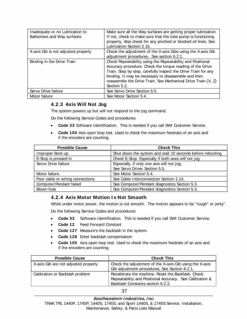
Inadequate or no Lubrication to Ballscrews and Way surfaces
Make sure all the Way surfaces are getting proper lubrication. If not, check to make sure that the lube pump is functioning properly. Also check for any pinched or blocked oil lines. See Lubrication Section 2.15.
X-axis Gib is not adjusted properly Check the adjustment of the X-axis Gibs using the X-axis Gib adjustment procedures. See section 6.2.1.
Binding in the Drive Train Check Repeatability using the Repeatability and Positional Accuracy procedure. Check the torque reading of the Drive Train. Step by step, carefully inspect the Drive Train for any binding. It may be necessary to disassemble and then reassemble the Drive Train. See Mechanical Drive Train (X, Z) Section 5.2.
Servo Drive failure See Servo Drive Section 5.5. Motor failure See Motor Section 5.4.
4.2.3 Axis Will Not Jog The system powers up but will not respond to the jog command.
Do the following Service Codes and procedures:
• Code 33 Software Identification. This is needed if you call SWI Customer Service.
• Code 100 Axis open loop test. Used to check the maximum feedrate of an axis and if the encoders are counting.
Possible Cause Check This
Improper Boot-up Shut down the system and wait 10 seconds before rebooting E-Stop is pressed in Check E-Stop. Especially if both axes will not jog Servo Drive failure Especially, if only one axis will not jog;
See Servo Driver Section 5.5. Motor failure See Motor Section 5.4. Poor cable or wiring connections See Cable Interconnection Section 2.14. Computer/Pendant failed See Computer/Pendant diagnostics Section 5.3. Blown fuse See Computer/Pendant diagnostics Section 5.3.
4.2.4 Axis Motor Motion Is Not Smooth While under motor power, the motion is not smooth. The motion appears to be "rough" or jerky”.
Do the following Service Codes and procedures:
• Code 33 Software Identification. This is needed if you call SWI Customer Service. • Code 12 Feed Forward Constant • Code 127 Measure's the backlash in the system. • Code 128 Enter backlash compensation • Code 100 Axis open loop test. Used to check the maximum feedrate of an axis and
if the encoders are counting.
Possible Cause Check This X-axis Gib are not adjusted properly Check the adjustment of the X-axis Gib using the X-axis
Gib adjustment procedures, See Section 6.2.1. Calibration or Backlash problem Recalibrate the machine. Reset the Backlash. Check
Repeatability and Positional Accuracy. See Calibration & Backlash Constants section 6.2.2.
Southwestern Industries, Inc.
TRAK TRL 1440P, 1745P, 1440S, 1745S, and Sport 1440S, & 1745S Service, Installation, Maintenance, Safety, & Parts Lists Manual
38
Binding in the Drive Train Check Repeatability using the Repeatability and Positional Accuracy procedure. Check the torque reading of the Drive Train. Step by step, carefully inspect the Drive Train for any binding. It may be necessary to disassemble and then reassemble the Drive Train. See Mechanical Drive Train (X, Z) Section 5.2.
Bad motor Check motion and slow feed rate. If problem is more frequent, replace motor.
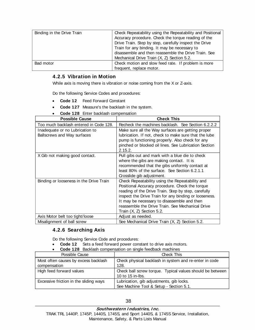
4.2.5 Vibration in Motion While axis is moving there is vibration or noise coming from the X or Z-axis. Do the following Service Codes and procedures:
• Code 12 Feed Forward Constant • Code 127 Measure's the backlash in the system. • Code 128 Enter backlash compensation
Possible Cause Check This Too much backlash entered in Code 128. Recheck the machines backlash. See Section 6.2.2.2 Inadequate or no Lubrication to Ballscrews and Way surfaces
Make sure all the Way surfaces are getting proper lubrication. If not, check to make sure that the lube pump is functioning properly. Also check for any pinched or blocked oil lines. See Lubrication Section 2.15.2.
X Gib not making good contact. Pull gibs out and mark with a blue die to check where the gibs are making contact. It is recommended that the gibs uniformly contact at least 80% of the surface. See Section 6.2.1.1 Crosslide gib adjustment.
Binding or looseness in the Drive Train Check Repeatability using the Repeatability and Positional Accuracy procedure. Check the torque reading of the Drive Train. Step by step, carefully inspect the Drive Train for any binding or looseness. It may be necessary to disassemble and then reassemble the Drive Train. See Mechanical Drive Train (X, Z) Section 5.2.
Axis Motor belt too tight/loose Adjust as needed. Misalignment of ball screw See Mechanical Drive Train (X, Z) Section 5.2.
4.2.6 Searching Axis
Do the following Service Code and procedures: • Code 12 Sets a feed forward power constant to drive axis motors. • Code 128 Backlash compensation on single feedback machines
Possible Cause Check This Most often causes by excess backlash compensation
Check physical backlash in system and re-enter in code 128.
High feed forward values Check ball screw torque. Typical values should be between 10 to 15 in-lbs.
Excessive friction in the sliding ways Lubrication, gib adjustments, gib locks. See Machine Tool & Setup - Section 5.1.
Southwestern Industries, Inc.
TRAK TRL 1440P, 1745P, 1440S, 1745S, and Sport 1440S, & 1745S Service, Installation, Maintenance, Safety, & Parts Lists Manual
39
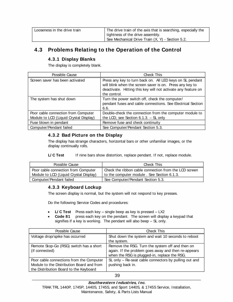
Looseness in the drive train The drive train of the axis that is searching, especially the tightness of the drive assembly. See Mechanical Drive Train (X, Y) - Section 5.2.
4.3 Problems Relating to the Operation of the Control
4.3.1 Display Blanks The display is completely blank.
Possible Cause Check This
Screen saver has been activated Press any key to turn back on. All LED keys on SL pendant will blink when the screen saver is on. Press any key to deactivate. Hitting this key will not activate any feature on the control.
The system has shut down Turn the power switch off, check the computer/ pendant fuses and cable connections. See Electrical Section 6.6.
Poor cable connection from Computer Module to LCD (Liquid Crystal Display)
Double-check the connection from the computer module to the LCD, see Section 6.1.3. – SL only
Fuse blown in pendant Remove fuse and check continuity Computer/Pendant failed See Computer/Pendant Section 5.3.
4.3.2 Bad Picture on the Display The display has strange characters, horizontal bars or other unfamiliar images, or the display continually rolls. L/C Test If nine bars show distortion, replace pendant. If not, replace module.
Possible Cause Check This
Poor cable connection from Computer Module to LCD (Liquid Crystal Display)
Check the ribbon cable connection from the LCD screen to the computer module . See Section 6.1.3.
Computer/Pendant failed See Computer/Pendant Section 5.3.
4.3.3 Keyboard Lockup The screen display is normal, but the system will not respond to key presses. Do the following Service Codes and procedures: • L/C Test Press each key – single beep as key is pressed – LX2 • Code 81 press each key on the pendant. The screen will display a keypad that
signifies if a key is working. The pendant will also beep – SL only.
Possible Cause Check This Voltage drop/spike has occurred Shut down the system and wait 10 seconds to reboot
the system. Remote Stop-Go (RSG) switch has a short (if connected)
Remove the RSG. Turn the system off and then on again. If the problem goes away and then re-appears when the RSG is plugged-in, replace the RSG.
Poor cable connections from the Computer Module to the Distribution Board and from the Distribution Board to the Keyboard
SL only – Re-seat cable connectors by pulling out and pushing back in.

Southwestern Industries, Inc.
TRAK TRL 1440P, 1745P, 1440S, 1745S, and Sport 1440S, & 1745S Service, Installation, Maintenance, Safety, & Parts Lists Manual
40
Computer/Pendant failed See Computer/Pendant Section 5.3. Electromagnetic interference has entered through the RS232 cable (if connected); especially if intermittent
Especially suspected if the RS232 cable is run near any electrical conduit. If the problem is chronic, remove the cable for a while to see if there is a difference.
4.3.4 Fault X or Z The program run or jogging operation is interrupted with a Fault Message on the display. Do the following Service Codes and procedures:
• Code 33 Software Identification. This is needed if you call SWI Customer Service.
• Code 12 Feed Forward Constant
• Code 100 Axis open loop test. Used to check the maximum feedrate of an axis and if the encoders are counting.
Possible Cause Check This
Servo cables at pendant switched around – SL only.
Make sure during an installation the X and Z servo cables at the pendant are in the correct ports.
X-axis Gibs are adjusted extremely tight Check the adjustment of the X-axis Gibs using the X Gib adjustment procedures. See X-axis Gib Adjustments Section 6.2.1.
Excessive friction in the slideways See Machine Tool & Setup Section 5.1. Binding or looseness in the Drive Train See Mechanical Drive Train (X, Z) Section 5.2. Incoming electrical power Incoming voltage. See Electrical Section 2.12. Servo Drive failure See Servo Driver - Section 5.5. Motor failure See Motor diagnostics, Section 5.4. Computer/Pendant failure See Computer/Pendant diagnostics, Section 5.3.
4.3.5 Problems Reading the Floppy Disk; Programs Not Saved Properly
The floppy drive will not read or write programs from a disk.
Possible Cause Check This Improper Boot-up Shut down the system and wait 10 seconds before
rebooting Floppy Disk failure Floppy Drive failure
The Floppy Disk may be bad. See if the Floppy Disk can be read by a Personal Computer. Does the green light on the floppy drive come on when you access the disk? If so, power is getting to the floppy drive. If not check connections of floppy drive inside the computer module. See Computer/Pendant Section 5.3 for more information.
Floppy Disk full Put the Floppy Disk into a Personal Computer to see how many bytes remain.
4.3.6 System Will Not Turn On or Boot-Up Nothing happens when the switch is turned on or the system does not boot-up.
Possible Cause Check This 110 V line is not plugged in Check incoming 110 V power source to black
electrical cabinet
Southwestern Industries, Inc.
TRAK TRL 1440P, 1745P, 1440S, 1745S, and Sport 1440S, & 1745S Service, Installation, Maintenance, Safety, & Parts Lists Manual
41
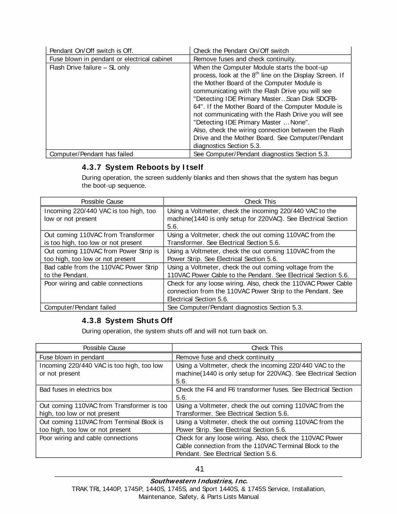
Pendant On/Off switch is Off. Check the Pendant On/Off switch Fuse blown in pendant or electrical cabinet Remove fuses and check continuity. Flash Drive failure – SL only When the Computer Module starts the boot-up
process, look at the 8th line on the Display Screen. If the Mother Board of the Computer Module is communicating with the Flash Drive you will see "Detecting IDE Primary Master…Scan Disk SDCFB-64". If the Mother Board of the Computer Module is not communicating with the Flash Drive you will see "Detecting IDE Primary Master … None". Also, check the wiring connection between the Flash Drive and the Mother Board. See Computer/Pendant diagnostics Section 5.3.
Computer/Pendant has failed See Computer/Pendant diagnostics Section 5.3.
4.3.7 System Reboots by Itself During operation, the screen suddenly blanks and then shows that the system has begun the boot-up sequence. Possible Cause Check This
Incoming 220/440 VAC is too high, too low or not present
Using a Voltmeter, check the incoming 220/440 VAC to the machine(1440 is only setup for 220VAC). See Electrical Section 5.6.
Out coming 110VAC from Transformer is too high, too low or not present
Using a Voltmeter, check the out coming 110VAC from the Transformer. See Electrical Section 5.6.
Out coming 110VAC from Power Strip is too high, too low or not present
Using a Voltmeter, check the out coming 110VAC from the Power Strip. See Electrical Section 5.6.
Bad cable from the 110VAC Power Strip to the Pendant.
Using a Voltmeter, check the out coming voltage from the 110VAC Power Cable to the Pendant. See Electrical Section 5.6.
Poor wiring and cable connections Check for any loose wiring. Also, check the 110VAC Power Cable connection from the 110VAC Power Strip to the Pendant. See Electrical Section 5.6.
Computer/Pendant failed See Computer/Pendant diagnostics Section 5.3.
4.3.8 System Shuts Off During operation, the system shuts off and will not turn back on. Possible Cause Check This
Fuse blown in pendant Remove fuse and check continuity Incoming 220/440 VAC is too high, too low or not present
Using a Voltmeter, check the incoming 220/440 VAC to the machine(1440 is only setup for 220VAC). See Electrical Section 5.6.
Bad fuses in electrics box Check the F4 and F6 transformer fuses. See Electrical Section 5.6.
Out coming 110VAC from Transformer is too high, too low or not present
Using a Voltmeter, check the out coming 110VAC from the Transformer. See Electrical Section 5.6.
Out coming 110VAC from Terminal Block is too high, too low or not present
Using a Voltmeter, check the out coming 110VAC from the Power Strip. See Electrical Section 5.6.
Poor wiring and cable connections Check for any loose wiring. Also, check the 110VAC Power Cable connection from the 110VAC Terminal Block to the Pendant. See Electrical Section 5.6.
Southwestern Industries, Inc.
TRAK TRL 1440P, 1745P, 1440S, 1745S, and Sport 1440S, & 1745S Service, Installation, Maintenance, Safety, & Parts Lists Manual
42
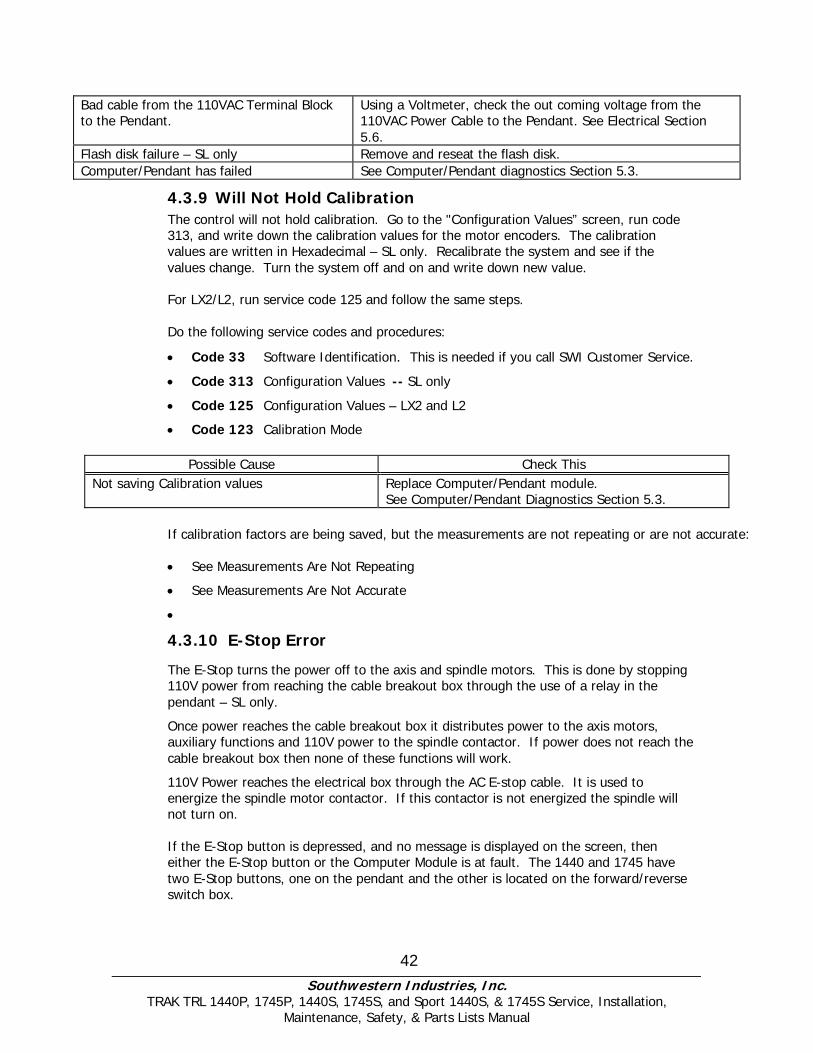
Bad cable from the 110VAC Terminal Block to the Pendant.
Using a Voltmeter, check the out coming voltage from the 110VAC Power Cable to the Pendant. See Electrical Section 5.6.
Flash disk failure – SL only Remove and reseat the flash disk. Computer/Pendant has failed See Computer/Pendant diagnostics Section 5.3.
4.3.9 Will Not Hold Calibration The control will not hold calibration. Go to the "Configuration Values” screen, run code 313, and write down the calibration values for the motor encoders. The calibration values are written in Hexadecimal – SL only. Recalibrate the system and see if the values change. Turn the system off and on and write down new value. For LX2/L2, run service code 125 and follow the same steps. Do the following service codes and procedures:
• Code 33 Software Identification. This is needed if you call SWI Customer Service.
• Code 313 Configuration Values -- SL only
• Code 125 Configuration Values – LX2 and L2
• Code 123 Calibration Mode
Possible Cause Check This Not saving Calibration values Replace Computer/Pendant module.
See Computer/Pendant Diagnostics Section 5.3.
If calibration factors are being saved, but the measurements are not repeating or are not accurate: • See Measurements Are Not Repeating
• See Measurements Are Not Accurate
•
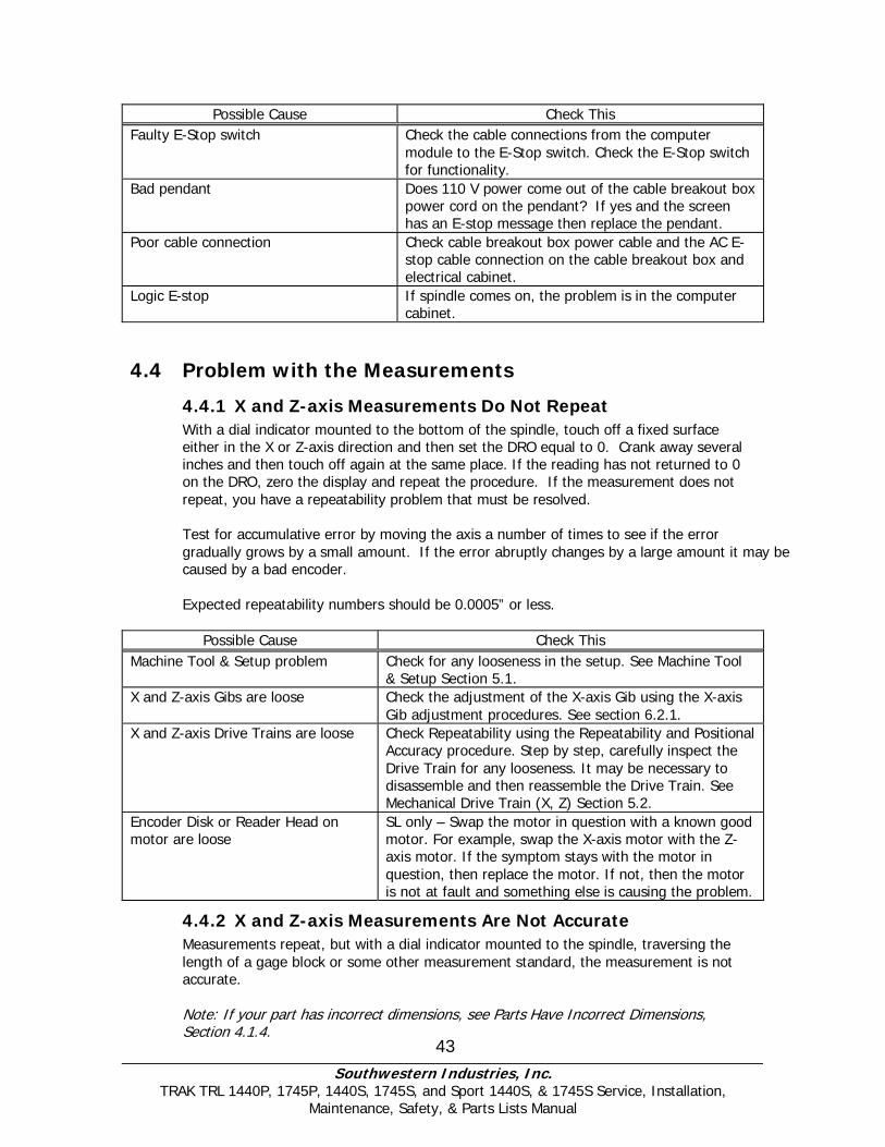
4.3.10 E-Stop Error
The E-Stop turns the power off to the axis and spindle motors. This is done by stopping 110V power from reaching the cable breakout box through the use of a relay in the pendant – SL only.
Once power reaches the cable breakout box it distributes power to the axis motors, auxiliary functions and 110V power to the spindle contactor. If power does not reach the cable breakout box then none of these functions will work.
110V Power reaches the electrical box through the AC E-stop cable. It is used to energize the spindle motor contactor. If this contactor is not energized the spindle will not turn on.
If the E-Stop button is depressed, and no message is displayed on the screen, then either the E-Stop button or the Computer Module is at fault. The 1440 and 1745 have two E-Stop buttons, one on the pendant and the other is located on the forward/reverse switch box.
Southwestern Industries, Inc.
TRAK TRL 1440P, 1745P, 1440S, 1745S, and Sport 1440S, & 1745S Service, Installation, Maintenance, Safety, & Parts Lists Manual
43
Possible Cause Check This Faulty E-Stop switch Check the cable connections from the computer
module to the E-Stop switch. Check the E-Stop switch for functionality.
Bad pendant Does 110 V power come out of the cable breakout box power cord on the pendant? If yes and the screen has an E-stop message then replace the pendant.
Poor cable connection Check cable breakout box power cable and the AC E-stop cable connection on the cable breakout box and electrical cabinet.
Logic E-stop If spindle comes on, the problem is in the computer cabinet.
4.4 Problem with the Measurements
4.4.1 X and Z-axis Measurements Do Not Repeat With a dial indicator mounted to the bottom of the spindle, touch off a fixed surface either in the X or Z-axis direction and then set the DRO equal to 0. Crank away several inches and then touch off again at the same place. If the reading has not returned to 0 on the DRO, zero the display and repeat the procedure. If the measurement does not repeat, you have a repeatability problem that must be resolved. Test for accumulative error by moving the axis a number of times to see if the error gradually grows by a small amount. If the error abruptly changes by a large amount it may be caused by a bad encoder. Expected repeatability numbers should be 0.0005” or less.
Possible Cause Check This Machine Tool & Setup problem Check for any looseness in the setup. See Machine Tool
& Setup Section 5.1. X and Z-axis Gibs are loose Check the adjustment of the X-axis Gib using the X-axis
Gib adjustment procedures. See section 6.2.1. X and Z-axis Drive Trains are loose Check Repeatability using the Repeatability and Positional
Accuracy procedure. Step by step, carefully inspect the Drive Train for any looseness. It may be necessary to disassemble and then reassemble the Drive Train. See Mechanical Drive Train (X, Z) Section 5.2.
Encoder Disk or Reader Head on motor are loose
SL only – Swap the motor in question with a known good motor. For example, swap the X-axis motor with the Z-axis motor. If the symptom stays with the motor in question, then replace the motor. If not, then the motor is not at fault and something else is causing the problem.
4.4.2 X and Z-axis Measurements Are Not Accurate Measurements repeat, but with a dial indicator mounted to the spindle, traversing the length of a gage block or some other measurement standard, the measurement is not accurate. Note: If your part has incorrect dimensions, see Parts Have Incorrect Dimensions, Section 4.1.4.

Southwestern Industries, Inc.
TRAK TRL 1440P, 1745P, 1440S, 1745S, and Sport 1440S, & 1745S Service, Installation, Maintenance, Safety, & Parts Lists Manual
44
Note: First check for repeatability of the DRO: With a dial indicator touch off a fixed surface either in the X or Z-axis direction and set the DRO equal to 0. Crank away several inches and touch off again at the same place. If the reading has not returned to 0 on the DRO, zero the display and repeat the procedure. If the measurement does not repeat, you have a repeatability problem that must be resolved before the accuracy problem can be resolved. See Measurements That Do Not Repeat, Section 4.4.1.
Possible Cause Do This
The Calibration is incorrect Recalibrate the machine. See Calibration & Backlash Constants
Incorrect backlash values If the machine does not repeat bi-directionally check the backlash on the axis in question. See Calibration and Backlash Constant Section 6.2.2.
4.4.3 The DRO Is Not Counting The DRO for one axis is not counting when an axis is moved. Often times if this is the case the axis will fault. See section on faulting. Do the following Service Codes:
• Code 33 Software Identification. This is needed if you call SWI Customer Service.
• Code 100 Axis open loop test. Used to check the maximum feedrate of an axis and if the encoders are counting.
• Code 132 Electronic handwheel test
Possible Cause Check This
Electronic handwheel failure Each handwheel should count 0.100” per revolution in both directions in fine mode and 0.8400” per revolution in course mode.
Servo driver failure Check the LED status on the axis in question. See Servo driver Section 5.5.
Motor Encoder not counting See Motor diagnostics Computer/Pendant failure See Computer/Pendant diagnostics section 5.3.
4.4.4 X and Z-axis DRO Counting in Wrong Direction The DRO is counting in the wrong direction. For 1440P/1745P and 1440/1745 Sport, use code 97 to configure the direction of the count. The positive directions for each axis are:
• X-axis – cross slide moves toward the operator
• Z-axis – carriage moves toward tailstock Do the following service code and procedures:
• Code 33 Software Identification. This is needed if you call SWI Customer Service.
• Code 313 Check the line that specifies the product. If the product does not match the machine then the machine ID key will need to be replaced.
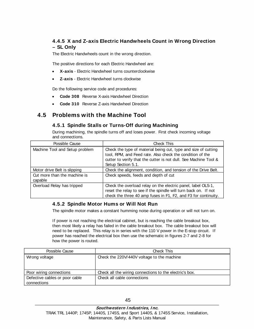
Southwestern Industries, Inc.
TRAK TRL 1440P, 1745P, 1440S, 1745S, and Sport 1440S, & 1745S Service, Installation, Maintenance, Safety, & Parts Lists Manual
45
4.4.5 X and Z-axis Electric Handwheels Count in Wrong Direction – SL Only The Electric Handwheels count in the wrong direction. The positive directions for each Electric Handwheel are:
• X-axis - Electric Handwheel turns counterclockwise
• Z-axis - Electric Handwheel turns clockwise Do the following service code and procedures:
• Code 308 Reverse X-axis Handwheel Direction
• Code 310 Reverse Z-axis Handwheel Direction
4.5 Problems with the Machine Tool
4.5.1 Spindle Stalls or Turns-Off during Machining During machining, the spindle turns off and loses power. First check incoming voltage and connections.
Possible Cause Check This Machine Tool and Setup problem Check the type of material being cut, type and size of cutting
tool, RPM, and Feed rate. Also check the condition of the cutter to verify that the cutter is not dull. See Machine Tool & Setup Section 5.1.
Motor drive Belt is slipping Check the alignment, condition, and tension of the Drive Belt. Cut more than the machine is capable
Check speeds, feeds and depth of cut
Overload Relay has tripped
Check the overload relay on the electric panel, label OLS-1, reset the relay to see if the spindle will turn back on. If not check the three 40 amp fuses in F1, F2, and F3 for continuity.
4.5.2 Spindle Motor Hums or Will Not Run The spindle motor makes a constant humming noise during operation or will not turn on. If power is not reaching the electrical cabinet, but is reaching the cable breakout box, then most likely a relay has failed in the cable breakout box. The cable breakout box will need to be replaced. This relay is in series with the 110 V power in the E-stop circuit. If power has reached the electrical box then use the schematic in figures 2-7 and 2-8 for how the power is routed.
Possible Cause Check This Wrong voltage
Check the 220V/440V voltage to the machine
Poor wiring connections Check all the wiring connections to the electric’s box. Defective cables or poor cable connections
Check all cable connections
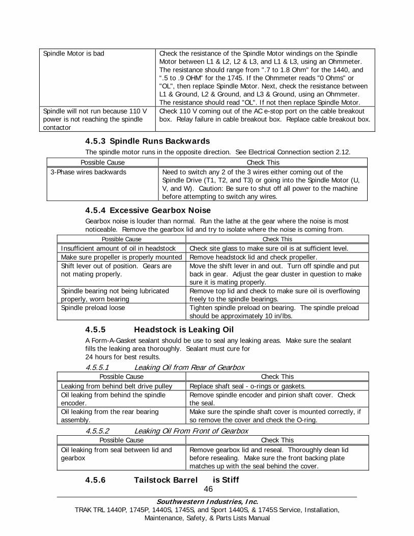
Southwestern Industries, Inc.
TRAK TRL 1440P, 1745P, 1440S, 1745S, and Sport 1440S, & 1745S Service, Installation, Maintenance, Safety, & Parts Lists Manual
46
Spindle Motor is bad Check the resistance of the Spindle Motor windings on the Spindle Motor between L1 & L2, L2 & L3, and L1 & L3, using an Ohmmeter. The resistance should range from ".7 to 1.8 Ohm" for the 1440, and “.5 to .9 OHM” for the 1745. If the Ohmmeter reads "0 Ohms" or "OL", then replace Spindle Motor. Next, check the resistance between L1 & Ground, L2 & Ground, and L3 & Ground, using an Ohmmeter. The resistance should read "OL". If not then replace Spindle Motor.
Spindle will not run because 110 V power is not reaching the spindle contactor
Check 110 V coming out of the AC e-stop port on the cable breakout box. Relay failure in cable breakout box. Replace cable breakout box.
4.5.3 Spindle Runs Backwards The spindle motor runs in the opposite direction. See Electrical Connection section 2.12.
Possible Cause Check This 3-Phase wires backwards Need to switch any 2 of the 3 wires either coming out of the
Spindle Drive (T1, T2, and T3) or going into the Spindle Motor (U, V, and W). Caution: Be sure to shut off all power to the machine before attempting to switch any wires.
4.5.4 Excessive Gearbox Noise Gearbox noise is louder than normal. Run the lathe at the gear where the noise is most noticeable. Remove the gearbox lid and try to isolate where the noise is coming from.
Possible Cause Check This Insufficient amount of oil in headstock Check site glass to make sure oil is at sufficient level. Make sure propeller is properly mounted Remove headstock lid and check propeller. Shift lever out of position. Gears are not mating properly.
Move the shift lever in and out. Turn off spindle and put back in gear. Adjust the gear cluster in question to make sure it is mating properly.
Spindle bearing not being lubricated properly, worn bearing
Remove top lid and check to make sure oil is overflowing freely to the spindle bearings.
Spindle preload loose Tighten spindle preload on bearing. The spindle preload should be approximately 10 in/lbs.
4.5.5 Headstock is Leaking Oil A Form-A-Gasket sealant should be use to seal any leaking areas. Make sure the sealant fills the leaking area thoroughly. Sealant must cure for
24 hours for best results.
4.5.5.1 Leaking Oil from Rear of Gearbox Possible Cause Check This
Leaking from behind belt drive pulley Replace shaft seal - o-rings or gaskets. Oil leaking from behind the spindle encoder.
Remove spindle encoder and pinion shaft cover. Check the seal.
Oil leaking from the rear bearing assembly.
Make sure the spindle shaft cover is mounted correctly, if so remove the cover and check the O-ring.
4.5.5.2 Leaking Oil From Front of Gearbox Possible Cause Check This
Oil leaking from seal between lid and gearbox
Remove gearbox lid and reseal. Thoroughly clean lid before resealing. Make sure the front backing plate matches up with the seal behind the cover.
4.5.6 Tailstock Barrel is Stiff

Southwestern Industries, Inc.
TRAK TRL 1440P, 1745P, 1440S, 1745S, and Sport 1440S, & 1745S Service, Installation, Maintenance, Safety, & Parts Lists Manual
47
The tailstock barrel is stiff or not smooth moving through its travel. The tailstock barrel subassembly jams inside the tailstock
Possible Cause Check This Misalignment of tailstock housing Realign bearing housing and tailstock screw. Loosen
screw support and realign. Too much grease. Disassemble and remove excess grease. Vernier Dial is binding or rubbing on screw support.
Remove dial and machine off a couple of thousandths or shim.
48 Southwestern Industries, Inc.
TRAK TRL 1440P, 1745P, 1440S, 1745S, and Sport 1440S, & 1745S Service, Installation, Maintenance, Safety, & Parts Lists Manual
5.0 Diagnostics This section explains the diagnostic procedures used to isolate service problems.
5.1 The Machine Tool & Set-Up
5.1.1 Leveling Leveling is one of the most important aspects of setting up the machine properly. Improper leveling can lead to a variety of machining problems.
The machine should be level to within .0008” longitudinally and .0005” transversely. See Leveling Procedures, Section 2.11.
5.1.1.1 Lag Bolting If vibration or chatter continues to be a problem after all other variables have been
covered, it is highly recommended to lag bolt the machine down to the floor.
Lag bolting should be down by an outside contractor. There are a lot of variables that need to be taken account of before the process begins. The contractor must look at such things as the floor capacity and the building foundation. SWI is not responsible for lag bolting a machine down.
5.1.2 A Special Word about the X Gib The X gib is vital to the performance of your lathe. Gibs should be:
• flat • free of twist • free of burrs • free of blockages in the oil passages and channels
Defective or scarred gibs must be replaced. Shimming of gibs will not yield acceptable results. It is good machining practice to avoid the use of shop air to clean the chips off a machine. This risks blowing chips into the sliding way surfaces and compromising the performance of the machine. See Gib Adjustments, Section 6.2.1.
5.1.3 Lubrication Lubrication is one of the single, most important maintenance issues and plays a key role in assuring the performance and durability of the lathe. At the beginning of each day manually supply oil to the way surfaces by manually overriding the oil pumping in the back of the lathe.
Lack of lubrication can lead to a variety of problems with your machine motion due to increased friction in the sliding ways. This increased friction may lead to part inaccuracies and decreased life expectancies of your ballscrews and way surfaces.
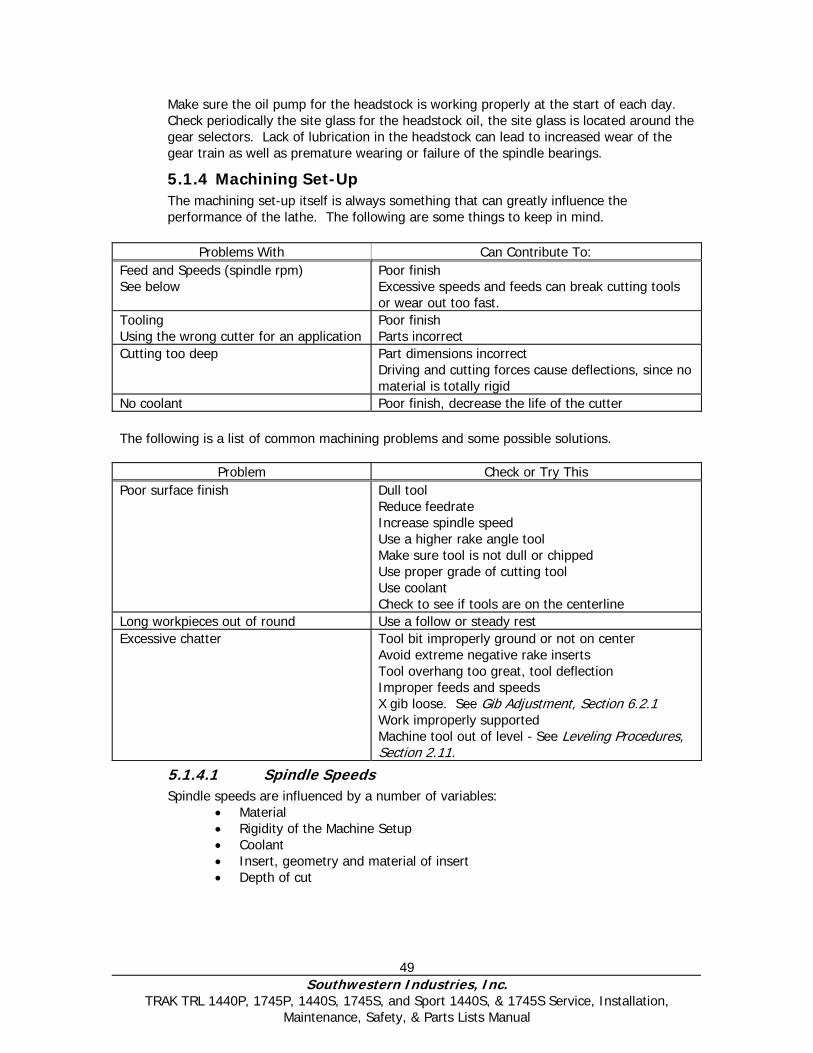
49 Southwestern Industries, Inc.
TRAK TRL 1440P, 1745P, 1440S, 1745S, and Sport 1440S, & 1745S Service, Installation, Maintenance, Safety, & Parts Lists Manual
Make sure the oil pump for the headstock is working properly at the start of each day. Check periodically the site glass for the headstock oil, the site glass is located around the gear selectors. Lack of lubrication in the headstock can lead to increased wear of the gear train as well as premature wearing or failure of the spindle bearings.
5.1.4 Machining Set-Up The machining set-up itself is always something that can greatly influence the performance of the lathe. The following are some things to keep in mind.
Problems With Can Contribute To:
Feed and Speeds (spindle rpm) See below
Poor finish Excessive speeds and feeds can break cutting tools or wear out too fast.
Tooling Using the wrong cutter for an application
Poor finish Parts incorrect
Cutting too deep Part dimensions incorrect Driving and cutting forces cause deflections, since no material is totally rigid
No coolant Poor finish, decrease the life of the cutter The following is a list of common machining problems and some possible solutions.
Problem Check or Try This Poor surface finish Dull tool
Reduce feedrate Increase spindle speed Use a higher rake angle tool Make sure tool is not dull or chipped Use proper grade of cutting tool Use coolant Check to see if tools are on the centerline
Long workpieces out of round Use a follow or steady rest Excessive chatter Tool bit improperly ground or not on center
Avoid extreme negative rake inserts Tool overhang too great, tool deflection Improper feeds and speeds X gib loose. See Gib Adjustment, Section 6.2.1 Work improperly supported Machine tool out of level - See Leveling Procedures, Section 2.11.
5.1.4.1 Spindle Speeds Spindle speeds are influenced by a number of variables:
• Material • Rigidity of the Machine Setup • Coolant • Insert, geometry and material of insert • Depth of cut
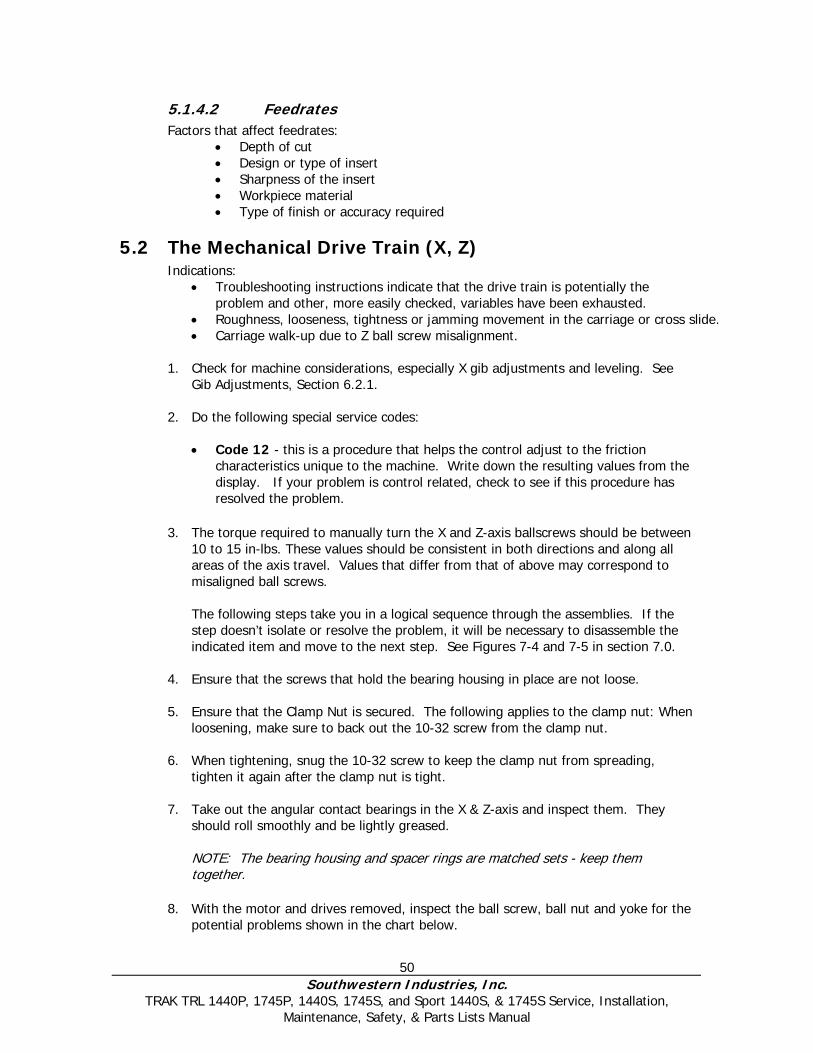
50 Southwestern Industries, Inc.
TRAK TRL 1440P, 1745P, 1440S, 1745S, and Sport 1440S, & 1745S Service, Installation, Maintenance, Safety, & Parts Lists Manual
5.1.4.2 Feedrates Factors that affect feedrates:
• Depth of cut • Design or type of insert • Sharpness of the insert • Workpiece material • Type of finish or accuracy required
5.2 The Mechanical Drive Train (X, Z) Indications:
• Troubleshooting instructions indicate that the drive train is potentially the problem and other, more easily checked, variables have been exhausted.
• Roughness, looseness, tightness or jamming movement in the carriage or cross slide. • Carriage walk-up due to Z ball screw misalignment.
1. Check for machine considerations, especially X gib adjustments and leveling. See
Gib Adjustments, Section 6.2.1. 2. Do the following special service codes:
• Code 12 - this is a procedure that helps the control adjust to the friction
characteristics unique to the machine. Write down the resulting values from the display. If your problem is control related, check to see if this procedure has resolved the problem.
3. The torque required to manually turn the X and Z-axis ballscrews should be between
10 to 15 in-lbs. These values should be consistent in both directions and along all areas of the axis travel. Values that differ from that of above may correspond to misaligned ball screws.
The following steps take you in a logical sequence through the assemblies. If the step doesn’t isolate or resolve the problem, it will be necessary to disassemble the indicated item and move to the next step. See Figures 7-4 and 7-5 in section 7.0.
4. Ensure that the screws that hold the bearing housing in place are not loose.
5. Ensure that the Clamp Nut is secured. The following applies to the clamp nut: When
loosening, make sure to back out the 10-32 screw from the clamp nut.
6. When tightening, snug the 10-32 screw to keep the clamp nut from spreading, tighten it again after the clamp nut is tight.
7. Take out the angular contact bearings in the X & Z-axis and inspect them. They
should roll smoothly and be lightly greased. NOTE: The bearing housing and spacer rings are matched sets - keep them together.
8. With the motor and drives removed, inspect the ball screw, ball nut and yoke for the potential problems shown in the chart below.
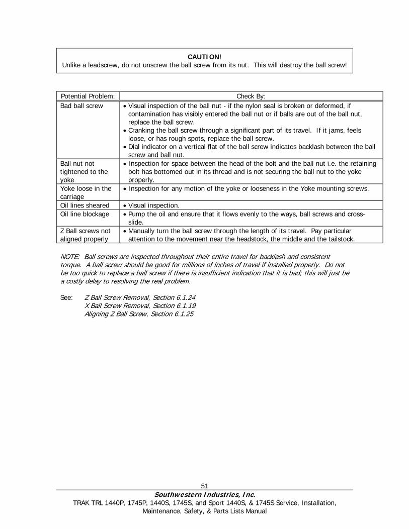
51 Southwestern Industries, Inc.
TRAK TRL 1440P, 1745P, 1440S, 1745S, and Sport 1440S, & 1745S Service, Installation, Maintenance, Safety, & Parts Lists Manual
CAUTION! Unlike a leadscrew, do not unscrew the ball screw from its nut. This will destroy the ball screw!
Potential Problem: Check By: Bad ball screw • Visual inspection of the ball nut - if the nylon seal is broken or deformed, if
contamination has visibly entered the ball nut or if balls are out of the ball nut, replace the ball screw.
• Cranking the ball screw through a significant part of its travel. If it jams, feels loose, or has rough spots, replace the ball screw.
• Dial indicator on a vertical flat of the ball screw indicates backlash between the ball screw and ball nut.
Ball nut not tightened to the yoke
• Inspection for space between the head of the bolt and the ball nut i.e. the retaining bolt has bottomed out in its thread and is not securing the ball nut to the yoke properly.
Yoke loose in the carriage
• Inspection for any motion of the yoke or looseness in the Yoke mounting screws.
Oil lines sheared • Visual inspection. Oil line blockage • Pump the oil and ensure that it flows evenly to the ways, ball screws and cross-
slide. Z Ball screws not aligned properly
• Manually turn the ball screw through the length of its travel. Pay particular attention to the movement near the headstock, the middle and the tailstock.
NOTE: Ball screws are inspected throughout their entire travel for backlash and consistent torque. A ball screw should be good for millions of inches of travel if installed properly. Do not be too quick to replace a ball screw if there is insufficient indication that it is bad; this will just be a costly delay to resolving the real problem. See: Z Ball Screw Removal, Section 6.1.24 X Ball Screw Removal, Section 6.1.19 Aligning Z Ball Screw, Section 6.1.25

52 Southwestern Industries, Inc.
TRAK TRL 1440P, 1745P, 1440S, 1745S, and Sport 1440S, & 1745S Service, Installation, Maintenance, Safety, & Parts Lists Manual
5.3 Computer/Pendant Diagnostics –
5.3.1 Computer/Pendant – Model SL The pendant consists of 3 separate modules: the computer module, flash drive module and the LCD screen enclosure. In general, the pendant/computer module is best diagnosed by eliminating all other possible alternatives. The following table lists some problems and what these problems can lead to.
Possible problems Can lead to
Poor cable connections There are 4 cable connections to the left side of the pendant. Make sure all cables are properly fastened.
Pendant locks up Press the E-stop button and see if lock up clears if not then do the following: Turn the pendant off, wait at least 30 seconds, and turn it back on and check to see if the malfunction has been reset.
No voltage to RSG port RSG will not work – should be 5 DC volts present Check with a voltmeter.
Low voltage to flash drive or slave board.
Can cause the system to lock up and the flash drive to act abnormally. Check voltage to power cable at flash drive module with voltmeter. It should be 4.8 DC volts and above. Lower values than this can cause problems.
Flash disk failure If the flash disk fails, the system will not boot up or operate. It will need to be replaced. All programs and machine configurations will be lost. Make sure to back up your flash drive from time to time. Only the flash drive module will need to be replaced.
Floppy disk failure Will not allow user to save or pull up programs from a floppy disk. Can the floppy drive format a disk? See Checking Floppy Drive Section 5.3.5.
LCD backlight burns out Check all cable connections to LCD, distribution board and computer module. Make sure the power is turned off before doing so.
Faulty E-stop switch It can be stuck open or closed (pressed). If it is stuck closed the pendant will need to be replaced because the user will have no way to get rid of the message. If it is open it will allow the machine to still operate but it will be unsafe for the user. The pendant will still need to be replaced.
Overlay failure (keys on pendant)
Certain buttons on overlay do not work. Do code 81 to verify each key beeps.
Low voltage to pendant or current spikes
1 amp fuse in pendant blows. Pendant will not turn on.
Slave board not functioning Machine will not run. If under Code 33 it says “Firmware Edge,” it means the slave board is not functioning.
5.3.2 Computer/Pendant – Model L2 In general, the Computer/Display problem is best diagnosed through a process of elimination. The following steps can be taken to help this process:
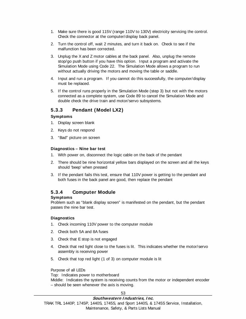
53 Southwestern Industries, Inc.
TRAK TRL 1440P, 1745P, 1440S, 1745S, and Sport 1440S, & 1745S Service, Installation, Maintenance, Safety, & Parts Lists Manual
1. Make sure there is good 115V (range 110V to 130V) electricity servicing the control. Check the connector at the computer/display back panel.
2. Turn the control off, wait 2 minutes, and turn it back on. Check to see if the malfunction has been corrected.
3. Unplug the X and Z motor cables at the back panel. Also, unplug the remote stop/go push button if you have this option. Input a program and activate the Simulation Mode using Code 22. The Simulation Mode allows a program to run without actually driving the motors and moving the table or saddle.
4. Input and run a program. If you cannot do this successfully, the computer/display must be replaced.
5. If the control runs properly in the Simulation Mode (step 3) but not with the motors connected as a complete system, use Code 89 to cancel the Simulation Mode and double check the drive train and motor/servo subsystems.
5.3.3 Pendant (Model LX2) Symptoms 1. Display screen blank
2. Keys do not respond
3. “Bad” picture on screen Diagnostics – Nine bar test 1. With power on, disconnect the logic cable on the back of the pendant
2. There should be nine horizontal yellow bars displayed on the screen and all the keys should ‘beep’ when pressed
3. If the pendant fails this test, ensure that 110V power is getting to the pendant and both fuses in the back panel are good, then replace the pendant
5.3.4 Computer Module Symptoms Problem such as “blank display screen” is manifested on the pendant, but the pendant passes the nine bar test.
Diagnostics 1. Check incoming 110V power to the computer module
2. Check both 5A and 8A fuses
3. Check that E stop is not engaged
4. Check that red light close to the fuses is lit. This indicates whether the motor/servo assembly is receiving power
5. Check that top red light (1 of 3) on computer module is lit
Purpose of all LEDs Top: Indicates power to motherboard Middle: Indicates the system is receiving counts from the motor or independent encoder – should be seen whenever the axis is moving.
54 Southwestern Industries, Inc.
TRAK TRL 1440P, 1745P, 1440S, 1745S, and Sport 1440S, & 1745S Service, Installation, Maintenance, Safety, & Parts Lists Manual
Lower: Indicates that the slave board is sending a command to move the motors – should be seen while attempting to jog an axis.
Failure of these lights to come on during the speed feed operation, indicates that the computer module should be replaced.
5.3.5 Checking Floppy Drive by Formatting a Disk 1. Find a new disk and install in floppy drive.
2. Install keyboard into middle port.
3. Press CTRL ESC to get to start menu.
4. Press R for run.
5. Type Format a: - press enter.
6. If the format works your disk drive is working. If format does not work, reboot control and see if it now works. If it does not work replace the computer module.
7. Press ALT ESC to get back to PT4 software.
5.4 Motor Diagnostics The Motor subsystem is comprised of 2 parts: The Motor Encoder and the Motor. The motors are powered by 110 VAC voltage. The servo driver is also an integral part of servo system, which is discussed in detail in the next section.
WARNING! Do not work with the motors unless the power is disconnected from the machine. The motors
are run by 110 VAC. There is possibility of death by electrocution!
Rarely do both the X and Z motor/servo systems fail at the same time and in the same way. So, if your problem is occurring on both axes, its source is probably somewhere else.
5.4.1 Cable Connections
Check the motor cable connections on the cable breakout box. Verify there are no pushed in pins on the connector.
5.4.2 To Check the Motor Encoders If the motor encoder inside the motor has failed or is not reading the machine will fault out on that axis. Do the following to verify this problem: Run Service Code 100 or 131. This will display on the DRO if the motor encoder is counting. If this axis does not count, the encoder is not counting. This means either the encoder or the cable is the problem. Visually check the cable for any problems. If the encoder has failed the motor must be replaced.
5.4.3 Encoder Counts to Pendant Before replacing the motor due to a bad motor encoder it is a good idea to check the cables that take those signals back to the pendant. If these signals are not getting back to the pendant then the axis will fault. Check the following cable connections. • Umbilical #1 and #2 at the encoder module
55 Southwestern Industries, Inc.
TRAK TRL 1440P, 1745P, 1440S, 1745S, and Sport 1440S, & 1745S Service, Installation, Maintenance, Safety, & Parts Lists Manual
• Umbilical #1 and #2 at the pendant
• Umbilical #1 carries the X-axis signals and Umbilical #2 carries the Z-axis signal.
5.4.4 Moving Problem from One Axis to Another Another way to troubleshoot a problem with a particular axis is to swap parts from 1 axis to another to see if the problem moves. If the problem moves then that component is faulty. See the example below.
Symptom – X Axis will not move and faults This particular problem can happen because of any of following reasons: bad motor, servo driver, power cable, or computer module. In some cases it is not always obvious which component is causing the problem. This example will help us pinpoint the problem through a trial and error process. Let’s assume we have narrowed it down to the servo or electrical systems and the Y-axis has no problems. Lets also assume it is not an obvious problem like a loose connection. This particular example was done on a machine with motor encoders only.
Swap these components Results
Physically switch the X and Z motors
Has problem moved to Z-axis? If yes, replace motor. If no, the motor is not the problem.
5.5 Servo Drivers Indications: • Problems moving just one axis. The axis faults out on the screen. Servo Types: • X is a light duty driver • Z is a heavy duty driver
Steps: 1. Turn off and unplug the system. 2. Check all connectors in the computer cabinet.
WARNING! Do not work with the Servo Driver unless the power is disconnected from the machine. There is
possibility of death by electrocution! Note: To avoid pulling the wires out of the connector, use the loop to pull the connector from the Servo Driver. If the problem moves to the other axis and clears up from the original axis, replace the Servo Driver.
5.6 Electrical
5.6.1 Checking A/C Voltage This procedure tests for the 115V power for the control.
• Use a Voltmeter, reading A/C volts.
56 Southwestern Industries, Inc.
TRAK TRL 1440P, 1745P, 1440S, 1745S, and Sport 1440S, & 1745S Service, Installation, Maintenance, Safety, & Parts Lists Manual
• Acceptable range is 110V to 130V Note: systems running consistently close to the high or low values may have problems when normal voltage fluctuations push the voltage out of the acceptable range. Our 1745 systems are shipped ready for either 220 VAC or 440VAC, and the 1440 is only setup for 220 VAC of power. The transformer secondary tap is set on 115 volts. Measure the voltage coming out of the transformer by placing the voltmeter across the 115 V and 0 V taps. If this measurement is above 120 volts then move the tap from 115 V to 110 V. If the reading is low, 110 V or below, then change the tap from 115 V to 124 V. Input power to the machine that is 230 V or above will cause the 110 voltage to be high and voltage that is 208 V or below typically causes 110 voltage to be low.
WARNING! Turn the main power off before changing the taps on the transformer. Failure to do this can
possibly cause death by electrocution!
5.6.2 Checking Fuses There are 12 fuses that make up the system on the 1440 and 1745. There are (2) two fuses in the pendant and (10) ten fuses in the electrical cabinet. To check fuses: 1. Use a Volt/Ohmmeter; select “OHM” or “Ω”.
2. Remove the fuse completely from the pendant display or computer module.
3. Place a lead of the meter on each end of the fuse.
• A good fuse reads 0 (zero) or close to it.
• A bad fuse reads Open or Infinity or OL (overload).
5.6.3 Fuse Indicator Lights LED lights are used to signify that there is power reaching certain components. The cable breakout box, lube pump, and floppy drive have an LED light. LED lights will only come on when the devices are in operation. If they do not come on when they should, check the fuse next to the light. If the light is still off, move further up the connection line to see if there is break in other parts of the line.
5.6.4 Cable Breakout Box Connections The Cable Breakout Box is located below the two servos (See Figure 6-1 for models L2 and SL). The list below describes what takes place through each connection. Power reaches the cable breakout box through AC IN from the pendant. From there power is distributed through the system.
• Umbilical #1 & Umbilical #2 Ports (To Pendant) - The lathes have (2) motor
encoder signals that are communicated between the Encoder module and the Pendant by use of (2) Umbilical cables. The X signal is communicated through umbilical #1 and the Z motor signal is transferred through umbilical #2.
• Apron Port - Communication for X & Z-handwheel and jogstick logic signals
between the Pendant and the cable breakout box.
57 Southwestern Industries, Inc.
TRAK TRL 1440P, 1745P, 1440S, 1745S, and Sport 1440S, & 1745S Service, Installation, Maintenance, Safety, & Parts Lists Manual
• X & Z- Servo Ports - This port is used to receive power and logic signals from the
X and Z- servos.
• X & Z - Motor Ports - are used to receive power from the servo and distribute it to the motors.
• X & Z-Motor Encoder Ports - These ports are used to receive logic signals from each of the X & Z-Motor Encoders.
• Spindle Encoder Port - The port is used to receive logic signals from the spindle encoder, when it is engaged for a threading routine.
• Logic to Servo (PWM) - This port is used to keep continuous feedback between the servos and the cable breakout box.
• 110 VAC Outlet - The outlet is for powering up the coolant pump. Beside the outlet is an LED light signifying power is reaching the pump when it is active, and a fuse to protect the pump.
• E-Stop and Spindle Out Port - used to disable power to the spindle motor when the E-Stop is activated.
5.6.5 Cable Connections The lathe machines use several cables to communicate between systems. It is often the case that what appears to be the failure of an electrical component is actually attributable to a poor connection. Indications:
• Control problems, chronic or intermittent.
• Motor problems
• Measurement problems Explanation: 1. Turn off and unplug the system from the wall.
WARNING!
Do not plug and unplug connectors with the system power on. This may cause damage to the connector board and harm to the technician.
2. Visually inspect the connections for excessive debris, moisture, or obvious damage.
3. Carefully clean any chips away from the connectors.
4. One-by-one, take out each connector and then plug them back in. Do the same at the computer/display.
5. Make sure the screws are tightened on each of the connectors.
5.6.6 Electrical Box The purpose of the electrical panel is to distribute power, protect the system, and relay switches.
58 Southwestern Industries, Inc.
TRAK TRL 1440P, 1745P, 1440S, 1745S, and Sport 1440S, & 1745S Service, Installation, Maintenance, Safety, & Parts Lists Manual
The electrical panel fuse and distribute 220 VAC 3 phase power from the power strip to the spindle motor. Also, 220 VAC single-phase power is input into the transformer to produce 110 V single-phase power, which is directed to the pendant.
The system is protected by a series of fuses. The 220/440 volt system, respectively, has (3) 40/20 amp fuses to protect the spindle motor and (3) 6/4 amp fuses to protect the coolant pump; two of which is also to protect the transformer. It also has (1) 4/2 amp fuses to protect the spindle magnetic braking system and (1) 8/4 amp fuse to protect the pendant. The power module also consist of relay switches: the spindle forward /reverse switch (K1/K2), E-stop Latch (K8), coolant pump trip (K4), brake timer (KT-1), and the Overload Trip (OLS). The 1440 will also include the HI/LO switch for the spindle motor relay (K5, K6, and K7), which is not present in the 1745. See Figure 5-1 – Power Panel.
5.7 Door Interlock Switch The 1440 and 1745 both use a door interlock switch to verify to the control that the door is closed in various modes of operation. This switch is wired normally open but is forced closed when the door is closed during CNC run mode. There should be continuity between pins 1 and 6 when the switch is forced closed and no continuity when the switch is in the open position. See Figure 7-3.
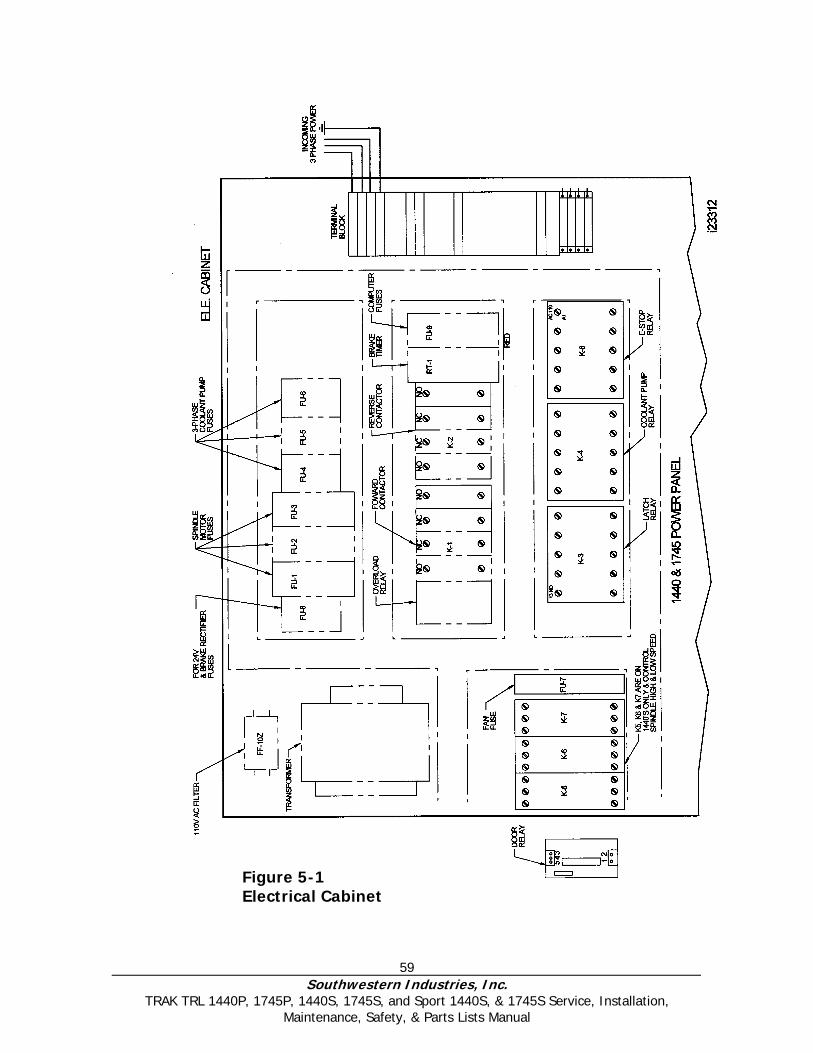
59 Southwestern Industries, Inc.
TRAK TRL 1440P, 1745P, 1440S, 1745S, and Sport 1440S, & 1745S Service, Installation, Maintenance, Safety, & Parts Lists Manual
Figure 5-1 Electrical Cabinet
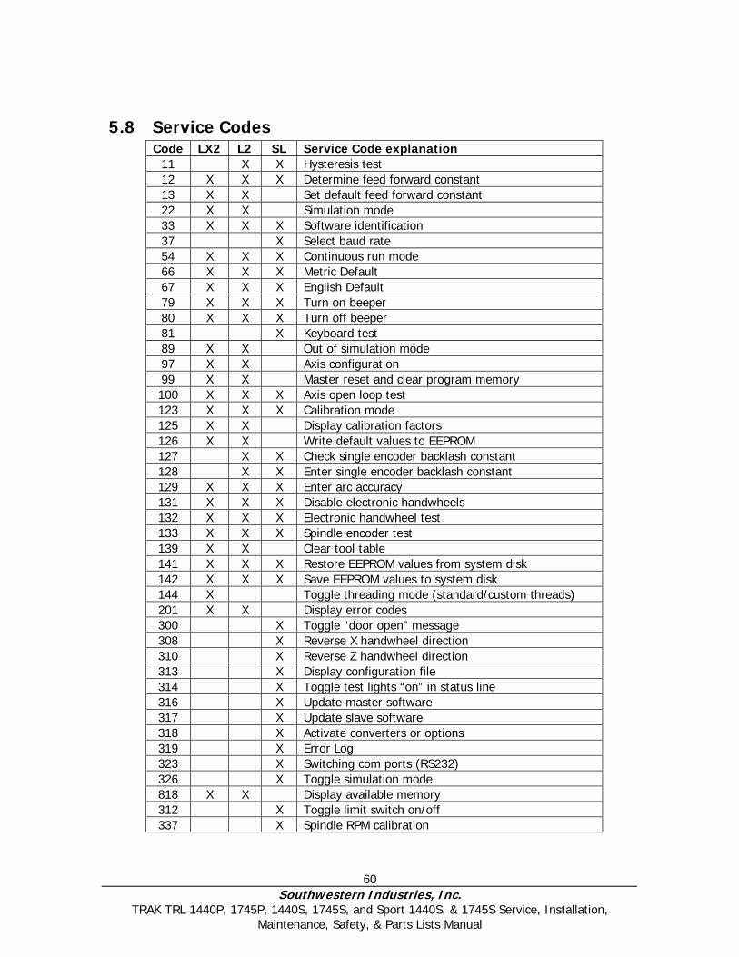
60 Southwestern Industries, Inc.
TRAK TRL 1440P, 1745P, 1440S, 1745S, and Sport 1440S, & 1745S Service, Installation, Maintenance, Safety, & Parts Lists Manual
5.8 Service Codes Code LX2 L2 SL Service Code explanation
11 X X Hysteresis test 12 X X X Determine feed forward constant 13 X X Set default feed forward constant 22 X X Simulation mode 33 X X X Software identification 37 X Select baud rate 54 X X X Continuous run mode 66 X X X Metric Default 67 X X X English Default 79 X X X Turn on beeper 80 X X X Turn off beeper 81 X Keyboard test 89 X X Out of simulation mode 97 X X Axis configuration 99 X X Master reset and clear program memory 100 X X X Axis open loop test 123 X X X Calibration mode 125 X X Display calibration factors 126 X X Write default values to EEPROM 127 X X Check single encoder backlash constant 128 X X Enter single encoder backlash constant 129 X X X Enter arc accuracy 131 X X X Disable electronic handwheels 132 X X X Electronic handwheel test 133 X X X Spindle encoder test 139 X X Clear tool table 141 X X X Restore EEPROM values from system disk 142 X X X Save EEPROM values to system disk 144 X Toggle threading mode (standard/custom threads) 201 X X Display error codes 300 X Toggle “door open” message 308 X Reverse X handwheel direction 310 X Reverse Z handwheel direction 313 X Display configuration file 314 X Toggle test lights “on” in status line 316 X Update master software 317 X Update slave software 318 X Activate converters or options 319 X Error Log 323 X Switching com ports (RS232) 326 X Toggle simulation mode 818 X X Display available memory 312 X Toggle limit switch on/off 337 X Spindle RPM calibration
61 Southwestern Industries, Inc.
TRAK TRL 1440P, 1745P, 1440S, 1745S, and Sport 1440S, & 1745S Service, Installation, Maintenance, Safety, & Parts Lists Manual
All service codes are accessed in the set up mode by pressing the soft key for “SERV CODES.” Some service codes generate movement of the axes – be careful. Service codes are broken down into the 4 following categories (SL control): software, machine setup, diagnostics, and user options/defaults. The service codes can be found under one of the headings listed on the main screen. Press the heading you want to access the code in question. If you know code # you want press the CODE # softkey and it will take you directly to the code in question. Press CODE #, enter the number you want, press SET.
5.8.1 Software Codes The following codes pertain to software functions in the control. To get to any of these codes go to Service Codes, press “A” and press the code you wish to view. Note - If you are working with the SWI Customer Service Group, write the values down for Code 33 or Code 313. These values will be valuable for troubleshooting.
5.8.1.1 Code 33: Software ID Code 33 is the software identification procedure. The two types of software in the control include:
• Software Version - the version of the system you have installed
• Firmware Version - the version of firmware software that is responsible for control to servo interface.
5.8.1.2 Code 37: RS232 Baud Rate
This code sets the baud rate for RS232 applications. The recommended baud rate is 9600. The following baud rates can be chosen: 4800, 9600, 19200, 38400, 57600, 115200.
5.8.1.3 Code 141: Load Configuration file from floppy “A” drive This code allows you to load your configuration file from the floppy disk to your hard drive. The configuration file consists of items such as calibration and backlash constants. This code is used when a computer module or hard drive has been replaced.
5.8.1.4 Code 142: Save Configuration file to floppy “A” drive This code allows you to save your configuration file to a floppy disk. The configuration file consists of items such as calibration and backlash constants. This code is used when a computer module or hard drive needs to be replaced. This stores the configuration file from the hard drive to the floppy disk. It is a good idea to do this code after the machine is initially setup so these values can be saved and used in the future. If the computer or hard drive fails, then you will not have the ability to save the configuration file and the machine will need to be re-setup when the computer or hard drive is replaced. Note: All machines will have a copy of the configuration file in the back of the electric’s cabinet.
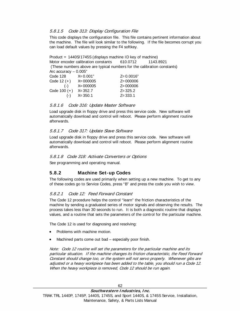
62 Southwestern Industries, Inc.
TRAK TRL 1440P, 1745P, 1440S, 1745S, and Sport 1440S, & 1745S Service, Installation, Maintenance, Safety, & Parts Lists Manual
5.8.1.5 Code 313: Display Configuration File This code displays the configuration file. This file contains pertinent information about the machine. The file will look similar to the following. If the file becomes corrupt you can load default values by pressing the F4 softkey. Product = 1440S/1745S (displays machine ID key of machine) Motor encoder calibration constants 610.0712 1143.8921 (These numbers above are typical numbers for the calibration constants) Arc accuracy – 0.005” Code 128 X=0.001” Z=0.0016” Code 12 (+) X=000005 Z=000006 (-) X=000005 Z=000006 Code 100 (+) X=352.7 Z=325.2 (-) X=350.1 Z=333.1
5.8.1.6 Code 316: Update Master Software Load upgrade disk in floppy drive and press this service code. New software will automatically download and control will reboot. Please perform alignment routine afterwards.
5.8.1.7 Code 317: Update Slave Software Load upgrade disk in floppy drive and press this service code. New software will automatically download and control will reboot. Please perform alignment routine afterwards.
5.8.1.8 Code 318: Activate Converters or Options See programming and operating manual.
5.8.2 Machine Set-up Codes The following codes are used primarily when setting up a new machine. To get to any of these codes go to Service Codes, press “B” and press the code you wish to view.
5.8.2.1 Code 12: Feed Forward Constant The Code 12 procedure helps the control “learn” the friction characteristics of the machine by sending a graduated series of motor signals and observing the results. The process takes less than 30 seconds to run. It is both a diagnostic routine that displays values, and a routine that sets the parameters of the control for the particular machine. The Code 12 is used for diagnosing and resolving:
• Problems with machine motion.
• Machined parts come out bad – especially poor finish. Note: Code 12 routine will set the parameters for the particular machine and its particular situation. If the machine changes its friction characteristic, the Feed Forward Constant should change too, or the system will not servo properly. Whenever gibs are adjusted or a heavy workpiece has been added to the table, you should run a Code 12. When the heavy workpiece is removed, Code 12 should be run again.
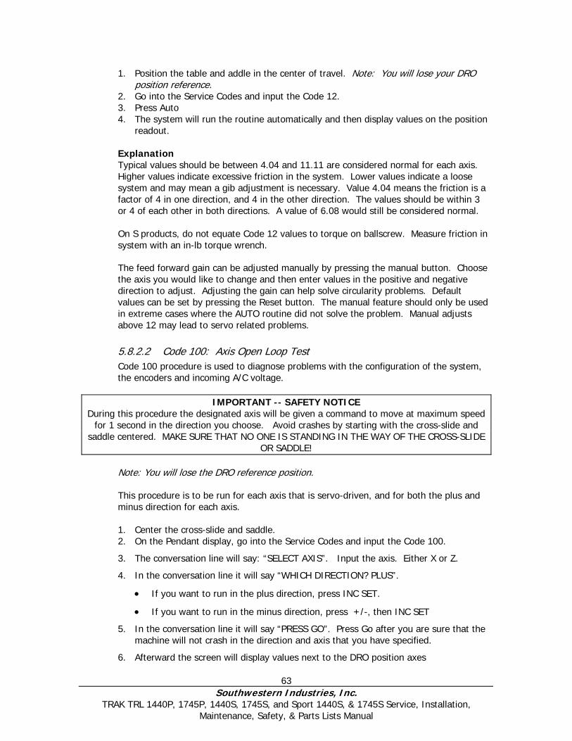
63 Southwestern Industries, Inc.
TRAK TRL 1440P, 1745P, 1440S, 1745S, and Sport 1440S, & 1745S Service, Installation, Maintenance, Safety, & Parts Lists Manual
1. Position the table and addle in the center of travel. Note: You will lose your DRO position reference.
2. Go into the Service Codes and input the Code 12. 3. Press Auto 4. The system will run the routine automatically and then display values on the position
readout. Explanation Typical values should be between 4.04 and 11.11 are considered normal for each axis. Higher values indicate excessive friction in the system. Lower values indicate a loose system and may mean a gib adjustment is necessary. Value 4.04 means the friction is a factor of 4 in one direction, and 4 in the other direction. The values should be within 3 or 4 of each other in both directions. A value of 6.08 would still be considered normal. On S products, do not equate Code 12 values to torque on ballscrew. Measure friction in system with an in-lb torque wrench.
The feed forward gain can be adjusted manually by pressing the manual button. Choose the axis you would like to change and then enter values in the positive and negative direction to adjust. Adjusting the gain can help solve circularity problems. Default values can be set by pressing the Reset button. The manual feature should only be used in extreme cases where the AUTO routine did not solve the problem. Manual adjusts above 12 may lead to servo related problems.
5.8.2.2 Code 100: Axis Open Loop Test Code 100 procedure is used to diagnose problems with the configuration of the system, the encoders and incoming A/C voltage.
IMPORTANT -- SAFETY NOTICE
During this procedure the designated axis will be given a command to move at maximum speed for 1 second in the direction you choose. Avoid crashes by starting with the cross-slide and
saddle centered. MAKE SURE THAT NO ONE IS STANDING IN THE WAY OF THE CROSS-SLIDE OR SADDLE!
Note: You will lose the DRO reference position. This procedure is to be run for each axis that is servo-driven, and for both the plus and minus direction for each axis.
1. Center the cross-slide and saddle. 2. On the Pendant display, go into the Service Codes and input the Code 100.
3. The conversation line will say: “SELECT AXIS”. Input the axis. Either X or Z.
4. In the conversation line it will say “WHICH DIRECTION? PLUS”.
• If you want to run in the plus direction, press INC SET.
• If you want to run in the minus direction, press +/-, then INC SET
5. In the conversation line it will say “PRESS GO”. Press Go after you are sure that the machine will not crash in the direction and axis that you have specified.
6. Afterward the screen will display values next to the DRO position axes
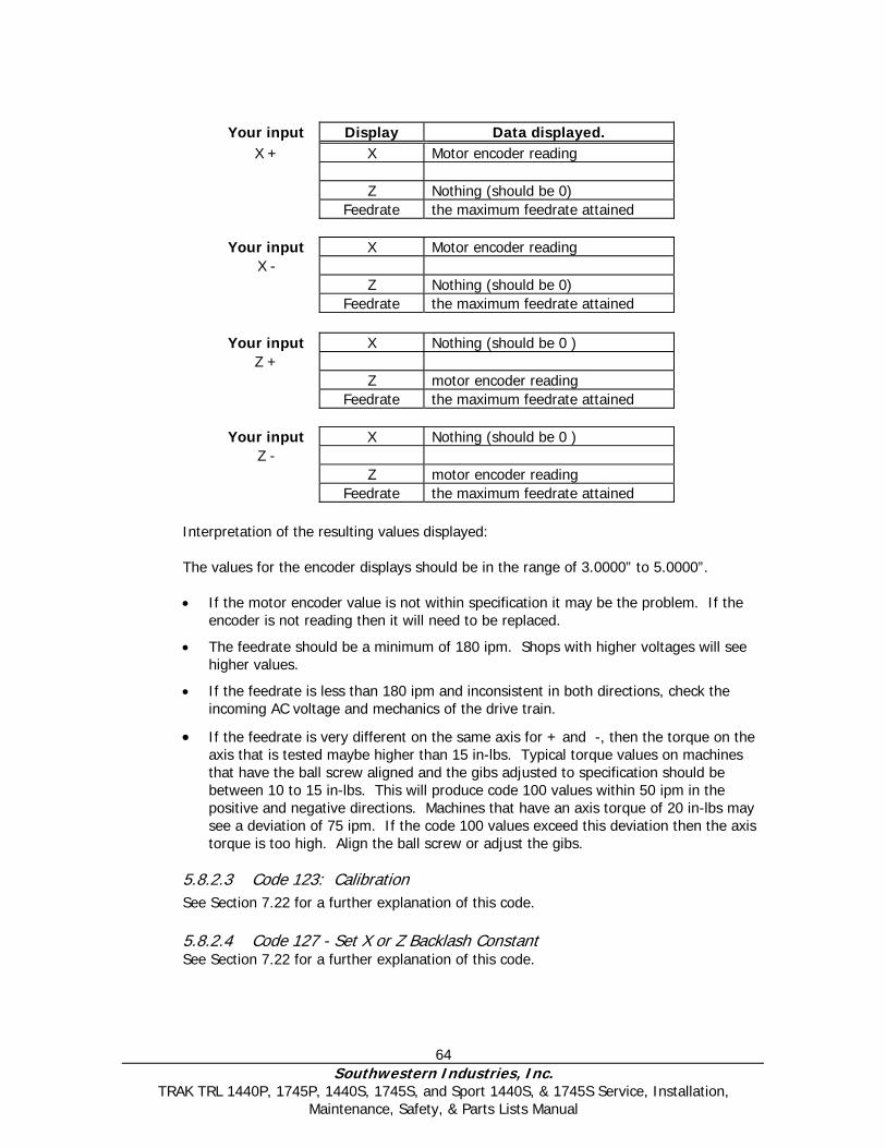
64 Southwestern Industries, Inc.
TRAK TRL 1440P, 1745P, 1440S, 1745S, and Sport 1440S, & 1745S Service, Installation, Maintenance, Safety, & Parts Lists Manual
Your input Display Data displayed.
X + X Motor encoder reading Z Nothing (should be 0) Feedrate the maximum feedrate attained
Your input X Motor encoder reading
X - Z Nothing (should be 0) Feedrate the maximum feedrate attained
Your input X Nothing (should be 0 )
Z + Z motor encoder reading Feedrate the maximum feedrate attained
Your input X Nothing (should be 0 )
Z - Z motor encoder reading Feedrate the maximum feedrate attained
Interpretation of the resulting values displayed: The values for the encoder displays should be in the range of 3.0000” to 5.0000”.
• If the motor encoder value is not within specification it may be the problem. If the
encoder is not reading then it will need to be replaced.
• The feedrate should be a minimum of 180 ipm. Shops with higher voltages will see higher values.
• If the feedrate is less than 180 ipm and inconsistent in both directions, check the incoming AC voltage and mechanics of the drive train.
• If the feedrate is very different on the same axis for + and -, then the torque on the axis that is tested maybe higher than 15 in-lbs. Typical torque values on machines that have the ball screw aligned and the gibs adjusted to specification should be between 10 to 15 in-lbs. This will produce code 100 values within 50 ipm in the positive and negative directions. Machines that have an axis torque of 20 in-lbs may see a deviation of 75 ipm. If the code 100 values exceed this deviation then the axis torque is too high. Align the ball screw or adjust the gibs.
5.8.2.3 Code 123: Calibration See Section 7.22 for a further explanation of this code. 5.8.2.4 Code 127 - Set X or Z Backlash Constant See Section 7.22 for a further explanation of this code.

65 Southwestern Industries, Inc.
TRAK TRL 1440P, 1745P, 1440S, 1745S, and Sport 1440S, & 1745S Service, Installation, Maintenance, Safety, & Parts Lists Manual
5.8.2.5 Code 128: Input Backlash Constant Code 128 allows you to enter the backlash values for each axis. It displays the value after it enters. This code is only used on machines with motor encoders only.
5.8.2.6 Code 308: Reverse X hand wheel direction This service code reverses the direction of the X hand wheel. 5.8.2.7 Code 310: Reverse Z hand wheel direction This service code reverses the direction of the Z hand wheel.
5.8.3 Diagnostic Codes The following codes are used primarily when diagnosing a problem with the machine. To get to any of these codes go to Service Codes, press “C” and press the code you wish to view – on SL control.
5.8.3.1 Code 54: Program Continuous Run This Code runs a program continuously without stopping for tool change commands. It is helpful in running a long period to identify an intermittent problem. 1. Prepare a program as you normally would.
2. Press MODE, SET UP, “C”, Code 54, INC SET. The program run will start automatically.
3. Press STOP to stop, and GO to continue.
5.8.3.2 Code 81: Keyboard Test
This code is used to check if the keyboard is functioning correctly. It allows you to test each key on the pendant individually. When you press the keys, the corresponding box for that key will highlight on the screen. The pendant will also beep, indicating that the key is working correctly. If one of the keys does not work the pendant assembly may need to be replaced. If none of the keys are working chances are that the computer module will need to be replaced.
5.8.3.3 Code 131: Manual DRO A manual diagnostic routine to check the motor encoder and table encoders. Turn the X hand wheel to display the encoder readings. This code will display the actual DRO counts and the raw encoder counts before the calibration and backlash factors have been factors into the counts.
5.8.3.4 Code 132 - Electronic Hand wheel Test Turn the X or Z-axis electronic hand wheel. The display should show movement as the hand wheel is being turned. There should be no skipping and it should count smoothly while the hand wheel is being turned. One revolution of hand wheel should read 0.4000” for Z and 0.1000” for X.
5.8.3.5 Code 133 – Spindle Encoder Test Turn the spindle or run the spindle at low RPM’s. The display should show the counts from the spindle encoder. It should count to 360 on the Z display and then reset. Each time it resets it displays the number in the X display area.

66 Southwestern Industries, Inc.
TRAK TRL 1440P, 1745P, 1440S, 1745S, and Sport 1440S, & 1745S Service, Installation, Maintenance, Safety, & Parts Lists Manual
5.8.3.6 Code 314: Toggle test lights ‘on’ in status line This code toggles on and off 2 test lights that appear in status line. The top light signifies if the master software is working. If functioning it should flash a green light. The bottom light signifies if the slave firmware is functioning. It will appear orange in run mode when it is processing information. Pressing the mode key will change this orange box to black. The orange box will also change to black when the program you are running reaches the 3rd event from the end of the program. If the firmware is locked up no keys will work. This code is useful for diagnosing intermittent problems with the control locking up.
5.8.3.7 Code 319: Error Log This code when turned on captures the commands that were sent to the servo system. It includes items such as positioning commands, errors, stop and go commands, etc. It may be helpful for identifying problems between programmed commands and executed commands. To turn on the error log press the F6 softkey. The page forward and backward keys allow you to scroll through the file one page at a time. The data forward and data backward keys allow you to scroll through the file one line at a time. The data bottom key takes you to the bottom of the file and then changes to data top which will take you back to the top. The file will capture data until the file reaches a size of approximately 600 Kb. At this time the file is saved to a backup file and the original file is cleared and data is once again captured. Once again as the file reaches a size of 600 Kb it copies over the previous backup file. From here the user can save the file to the floppy drive by pressing the F8 softkey. Once this in done it prompts you for which file you want to save to disk. The F1 key saves the current file to disk and the F2 key saves the backup file to disk. To clear the files press the F7 softkey. 5.8.3.8 Code 326: Error Message Display Error Message Display is used to describes error messages.
5.8.4 Operator Defaults/Options Codes The following codes allow the user to set programming defaults or turn features on or off. To get to any of these codes go to Service Codes, press “D” and press the code you wish to view.
5.8.4.1 Code 66: Default Metric This code causes the control to turn on in the metric mode.
5.8.4.2 Code 67: Default English This code causes the control to turn on in the English mode.
5.8.4.3 Code 79: Beeper On This turns on the beeper to the control keys.
5.8.4.4 Code 80: Beeper Off This turns off the beeper to the control keys.
5.8.4.5 Code 129: Arc Accuracy When the SL control operates at high feedrates it may create small part machining errors as it goes around sharp corners. This exists on all CNC’s and is commonly called a

67 Southwestern Industries, Inc.
TRAK TRL 1440P, 1745P, 1440S, 1745S, and Sport 1440S, & 1745S Service, Installation, Maintenance, Safety, & Parts Lists Manual
“following error.” The control is factory preset to allow a maximum following error of 0.005 inch. The feedrate will automatically be adjusted around sharp corners so as to not violate this limit. This code only applies to arcs that are programmed and ones that are created in the tool path to generate the shape you want. This code will not make a difference on mill moves. You may adjust the maximum following error to a value as small as .0001 inch. However, the smaller the value, the slower the feedrate around corners. To input a new Following Error use the following procedure:
Follow the instructions on the screen and input the Following Error value (from .0001 to .0100) and press INC SET.
5.8.4.6 Code 323: RS232 Com Port
This code switches between COM ports for RS232 applications.

68 Southwestern Industries, Inc.
TRAK TRL 1440P, 1745P, 1440S, 1745S, and Sport 1440S, & 1745S Service, Installation, Maintenance, Safety, & Parts Lists Manual
6.0 Procedures for Replacements & Maintenance
6.1 Replacements This section of the manual contains essential information only for replacing components of the TRL. Details may be seen on the referenced drawings. Note: Before performing any service procedure, refer to Section 1, "Safety" of this manual.
6.1.1 Motor Replacement 1. Turn off power to the machine. 2. Each motor is mounted by the use of (4) ¼-20 screws. Be careful not to over
tighten these bolts and strip the threads.
6.1.2 Servo Driver Replacement WARNING!
Do not work with the Servo Drivers unless the power is disconnected from the machine. The servo drivers are run by 110 VAC. There is possibility of death by electrocution!
The Servo Driver for each axis is located inside the electric cabinet.
DANGER! Always engage (push in) the Emergency Stop switch, turn the ProtoTRAK Control off, and
disconnect the servo driver cable at the cable breakout box.
1. Press in the Emergency Stop. 2. Remove the servo driver from the panel, inside the electric cabinet. 3. Remove the 10 cap screws that hold the servo driver and its heat sink plate to the panel. 4. Disconnect the cable connector from the servo driver. 5. Reinstall the new servo driver with its heat sink plate.
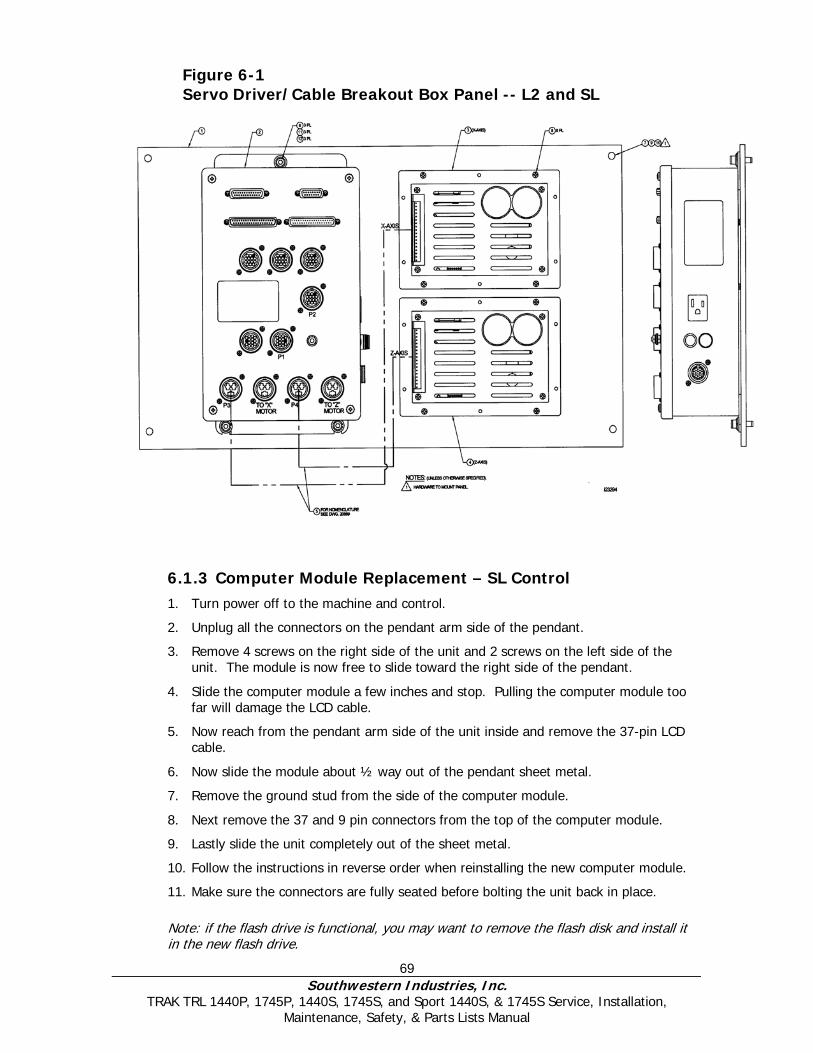
69 Southwestern Industries, Inc.
TRAK TRL 1440P, 1745P, 1440S, 1745S, and Sport 1440S, & 1745S Service, Installation, Maintenance, Safety, & Parts Lists Manual
6.1.3 Computer Module Replacement – SL Control 1. Turn power off to the machine and control.
2. Unplug all the connectors on the pendant arm side of the pendant.
3. Remove 4 screws on the right side of the unit and 2 screws on the left side of the unit. The module is now free to slide toward the right side of the pendant.
4. Slide the computer module a few inches and stop. Pulling the computer module too far will damage the LCD cable.
5. Now reach from the pendant arm side of the unit inside and remove the 37-pin LCD cable.
6. Now slide the module about ½ way out of the pendant sheet metal.
7. Remove the ground stud from the side of the computer module.
8. Next remove the 37 and 9 pin connectors from the top of the computer module.
9. Lastly slide the unit completely out of the sheet metal.
10. Follow the instructions in reverse order when reinstalling the new computer module.
11. Make sure the connectors are fully seated before bolting the unit back in place.
Note: if the flash drive is functional, you may want to remove the flash disk and install it in the new flash drive.
Figure 6-1 Servo Driver/Cable Breakout Box Panel -- L2 and SL
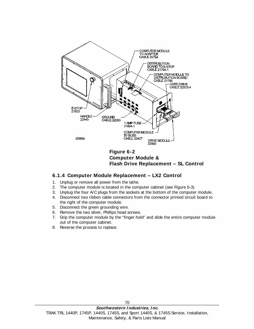
70 Southwestern Industries, Inc.
TRAK TRL 1440P, 1745P, 1440S, 1745S, and Sport 1440S, & 1745S Service, Installation, Maintenance, Safety, & Parts Lists Manual
6.1.4 Computer Module Replacement – LX2 Control 1. Unplug or remove all power from the lathe. 2. The computer module is located in the computer cabinet (see Figure 6-3) 3. Unplug the four A/C plugs from the sockets at the bottom of the computer module. 4. Disconnect two ribbon cable connectors from the connector printed circuit board to
the right of the computer module. 5. Disconnect the green grounding wire. 6. Remove the two silver, Phillips head screws. 7. Grip the computer module by the “finger hold” and slide the entire computer module
out of the computer cabinet. 8. Reverse the process to replace.
Figure 6-2 Computer Module & Flash Drive Replacement – SL Control
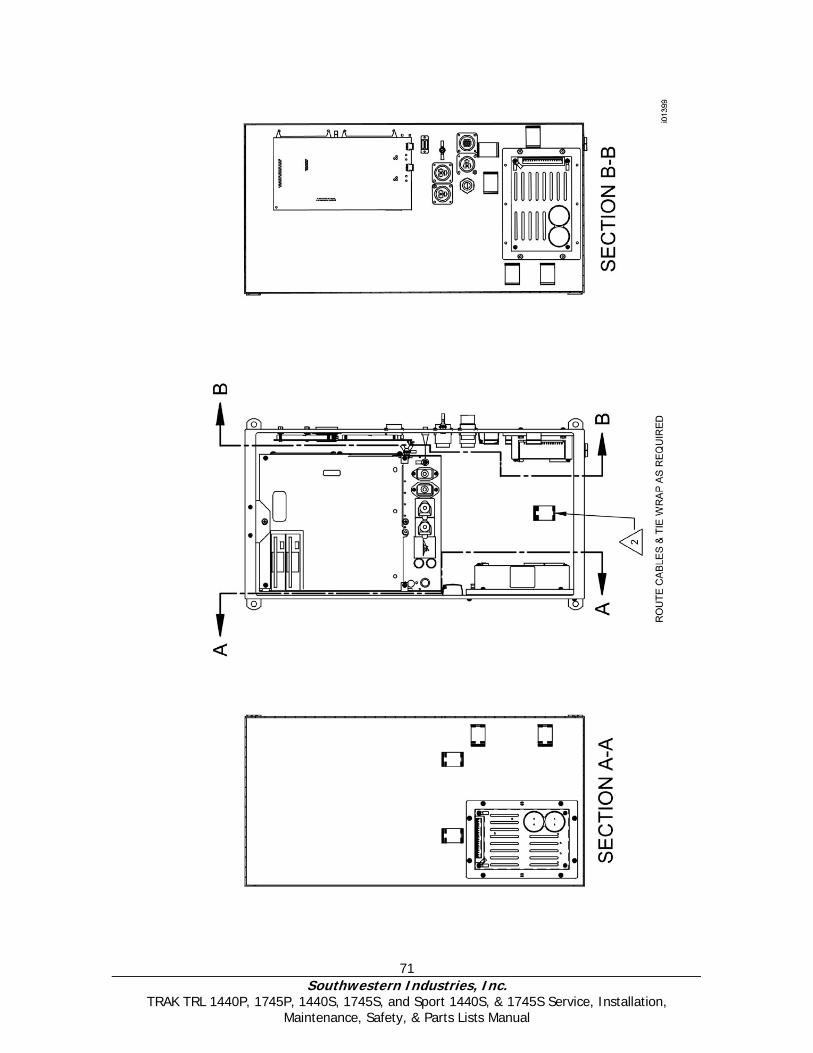
71 Southwestern Industries, Inc.
TRAK TRL 1440P, 1745P, 1440S, 1745S, and Sport 1440S, & 1745S Service, Installation, Maintenance, Safety, & Parts Lists Manual
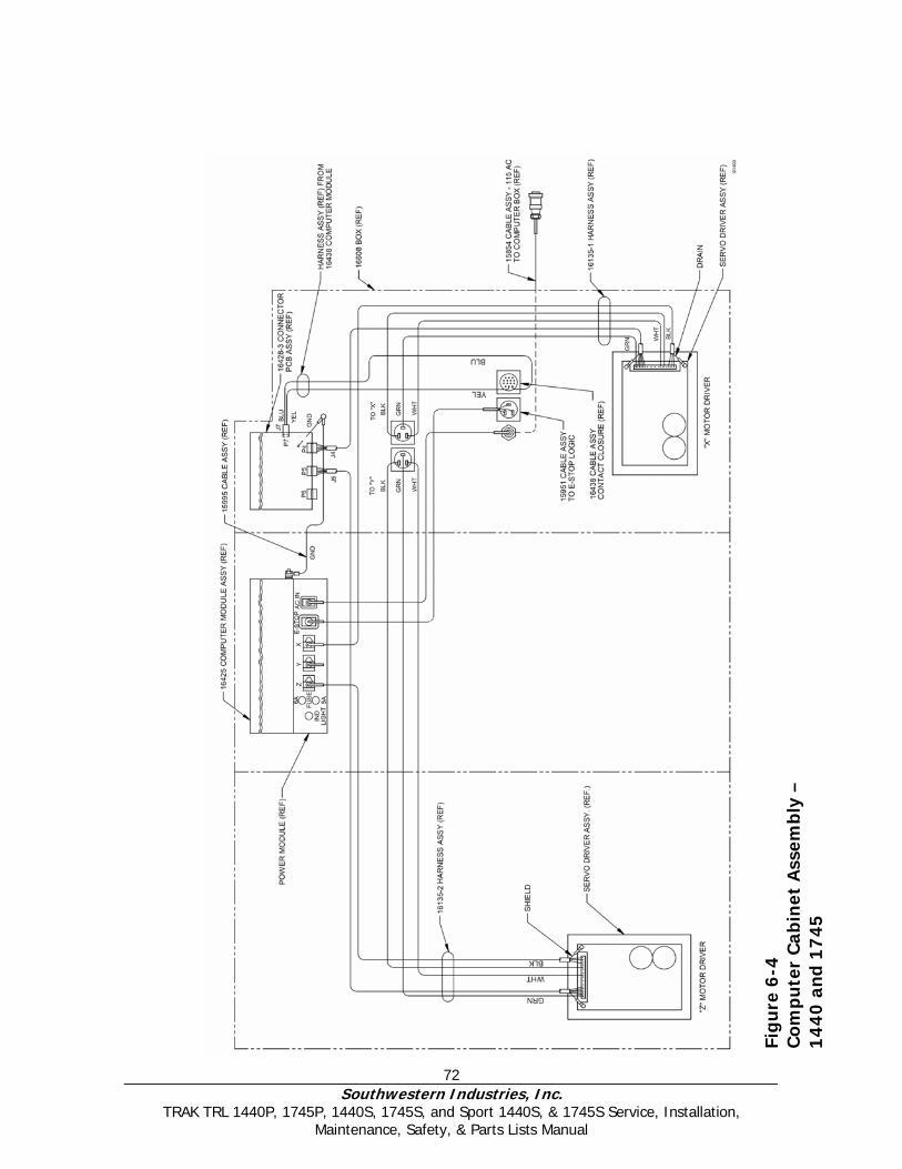
72 Southwestern Industries, Inc.
TRAK TRL 1440P, 1745P, 1440S, 1745S, and Sport 1440S, & 1745S Service, Installation, Maintenance, Safety, & Parts Lists Manual
Fig
ure
6-4
C
omp
ute
r C
abin
et A
ssem
bly
–
14
40
and
17
45
73 Southwestern Industries, Inc.
TRAK TRL 1440P, 1745P, 1440S, 1745S, and Sport 1440S, & 1745S Service, Installation, Maintenance, Safety, & Parts Lists Manual
6.1.5 System Flash Disk Replacement The system software for the SL control is contained on a 64 MB flash disk that is located under the door on the right side of the pendant in the upper flash drive slot. If this needs to be replaced, push the bottom to eject the disk and reload the new disk. Turn power off to the machine before doing this replacement.
CAUTION!
It is a good idea to back up your flash drive from time to time via a network or floppy disk. If your flash drive needs to be replaced you will loose all of your programs. See your programming
manual for instruction on how to do this.
6.1.6 Cable Routing on Machine Whenever you replace a cable or reroute a cable it is very important to keep the power cables and logic cables separated from each other. The power cables consist of the (2) 110-volt motor cables and (2) 110-volt power cables for the pendant, and a coolant pump or solenoid power cable. The logic cables are used to carry encoder signals between the cable breakout box and computer module. Mixing of the power and logic cables may cause noise from the power cables to interrupt the signals in the logic cables. This can lead to intermittent axis faults or repeatability problems.
6.1.7 Electronic Handwheels & Jogstick There are 2 electronic handwheels on the lathes and 1 jogstick to move the carriage quickly into position. Each unit is replaced as an assembly. Disconnect the handwheels and jogstick from the apron cable.
6.1.8 Z Axis Electronic Handwheel Removal (See Figure 7-19) 1. Unplug or remove all power from the lathe.
2. Remove the handwheel from the apron. It is not necessary to remove the apron.
3. The electronic handwheel assembly is only available as a complete unit. Do not
disassemble.
6.1.9 X Axis Electronic Handwheel Removal (See Figure 7-19) 1. Unplug or remove all power from the lathe. 2. Remove the handwheel from the apron. It is not necessary to remove the apron. 3. The electronic handwheel assembly is only available as a complete unit. Do not
disassemble.
6.1.10 Jogstick Removal (See Figure 7-19) 1. Unplug or remove all power from the lathe. 2. Remove the jog stick from the apron. It is not necessary to remove the apron.
3. The jogstick assembly is only available as a complete unit. Do not disassemble.

74 Southwestern Industries, Inc.
TRAK TRL 1440P, 1745P, 1440S, 1745S, and Sport 1440S, & 1745S Service, Installation, Maintenance, Safety, & Parts Lists Manual
6.1.11 Spindle Forward/Reverse Switch (See Figure 7-19) 1. Unplug or remove all power from the lathe. 2. The forward/reverse switch is mounted on the apron. It is not necessary to remove
the apron to remove the switch.
6.1.12 Cable Routing in Electrics Box Bellow the electric cabinet is a cover encasing the extra cables beneath the cabinet. Whenever you replace a cable or reroute a cable it is very important to keep the power cables and logic cables separated from each other. The power cables consist of the (2) 110 volt servo motor cables and (4) 110-volt power cables for the pendant, spindle motor fan, coolant pump, and lube pump. The logic cables are used to carry signals between modules, handwheels, encoders, etc. Mixing of the power and logic cables may cause noise from the power cables to interrupt the signals in the logic cables. This can lead to intermittent axis faults or repeatability problems.
6.1.13 Spindle Encoder Replacement (see Figure 7-16) 1. Unplug or remove all power from the lathe.
2. Open the rear spindle cover (located on the left side) to gain access to the encoder.
3. Loosen setscrews on flexible coupling and the bolts that hold the encoder on.
4. Slide the encoder off.
5. The spindle encoder assembly is only available as a complete unit. Do not disassemble.
6.1.14 Brake Removal (see Figure 6-5) 1. Unplug or remove all power from the lathe.
2. The brake is located on the spindle motor shaft.
3. Loosen and remove bolt (Item 6), and clamp (Item 5).
4. Remove brake half (Item 4).
5. Remove attaching screws (Item 2), and brake half (Item 3).
6. The brake assembly is only available as a complete unit. Do not disassemble.
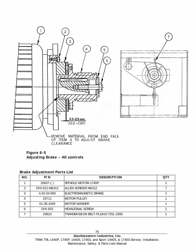
75 Southwestern Industries, Inc.
TRAK TRL 1440P, 1745P, 1440S, 1745S, and Sport 1440S, & 1745S Service, Installation, Maintenance, Safety, & Parts Lists Manual
Brake Adjustment Parts List
NO. P/N DESCRIPTION QTY
1 20637-( ) SPINDLE MOTOR-1745P 1
2 DIN 912-M6X12 ALLEN SCREWS M6X12 7
3 4.62.04.900 ELECTROMAGNETIC BRAKE 1
4 20711 MOTOR PULLEY 1
5 01.08.1049 MOTOR WASHER 1
6 DIN 933 HEXAGONAL SCREW 1
7 20810 TRANSMISSION BELT-PL1842/725L-2395 1
Figure 6-5 Adjusting Brake – All controls
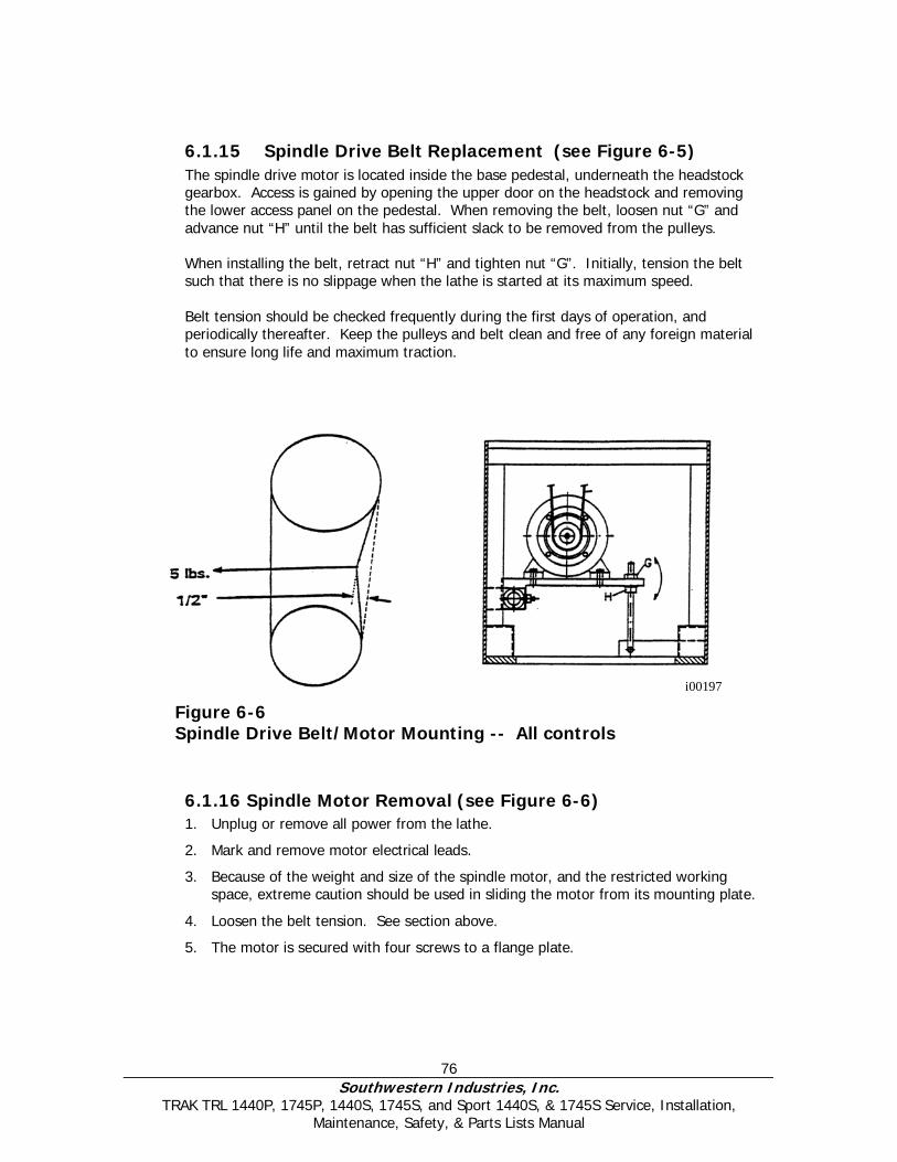
76 Southwestern Industries, Inc.
TRAK TRL 1440P, 1745P, 1440S, 1745S, and Sport 1440S, & 1745S Service, Installation, Maintenance, Safety, & Parts Lists Manual
6.1.15 Spindle Drive Belt Replacement (see Figure 6-5) The spindle drive motor is located inside the base pedestal, underneath the headstock gearbox. Access is gained by opening the upper door on the headstock and removing the lower access panel on the pedestal. When removing the belt, loosen nut “G” and advance nut “H” until the belt has sufficient slack to be removed from the pulleys. When installing the belt, retract nut “H” and tighten nut “G”. Initially, tension the belt such that there is no slippage when the lathe is started at its maximum speed. Belt tension should be checked frequently during the first days of operation, and periodically thereafter. Keep the pulleys and belt clean and free of any foreign material to ensure long life and maximum traction.
6.1.16 Spindle Motor Removal (see Figure 6-6) 1. Unplug or remove all power from the lathe.
2. Mark and remove motor electrical leads.
3. Because of the weight and size of the spindle motor, and the restricted working space, extreme caution should be used in sliding the motor from its mounting plate.
4. Loosen the belt tension. See section above.
5. The motor is secured with four screws to a flange plate.
Figure 6-6 Spindle Drive Belt/Motor Mounting -- All controls
i00197

77 Southwestern Industries, Inc.
TRAK TRL 1440P, 1745P, 1440S, 1745S, and Sport 1440S, & 1745S Service, Installation, Maintenance, Safety, & Parts Lists Manual
6.1.17 X Axis Ballscrew Encoder Assembly – 1440P/1745P – LX2 & 1440P/1745P Sport
1. Unplug or remove all power from the lathe.
2. Access to the X axis encoder assembly is gained by removing the splash guard at the back of the lathe and then removing the cover (see figure 7-26).
3. The flexible coupling at the end of the ballscrew will remain with the encoder assembly after it is removed from the ballscrew.
4. The encoder assembly is only available as a complete unit. Do not disassemble.
5. The X and Z encoder assemblies are not interchangeable.
Note: The flexible coupling screws onto the end of the ballscrew and then with set screws.
6.1.18 X Axis Motor Removal 1. Unplug or remove all power from the lathe.
2. Access to the X axis motor assembly is gained by removing the chip guard at the back of the lathe and then removing the cover (see figures 7-4 and 7-26).
3. It will be necessary to remove the cable with the motor. The cable extends through the cable carrier to the computer cabinet.
4. X and Z motors are not interchangeable.
6.1.19 X-Axis Ball Screw Removal (see Figure 7-4 and 7-26) 1. Unplug or remove all power from the lathe. 2. Access to the X-axis ball screw is gained by removing the back chip guard and
removing the X-axis motor cover. 3. Remove the motor. 4. Remove all items on the right end of the ball screw. See the Figure 7-4 and 7-26. 5. Unbolt the ballscrew nut from the yoke. 6. The X ball screw is removed through the exposed hole when the cross slide is
removed.
6.1.20 Installing Angular Contact Bearings 1. On the inner race of the angular contact bearings, the thin walls face each other.
2. When tightening the clamp nut, first engage a few threads. Then lightly tighten the locking screw slowly, so that when you slowly thread the lock nut inwards you can feel some contact between the two threads.
3. Once the clamp nut is completely threaded inwards you will need to use a torque wrench to apply 50 ft/lb. of torque, properly seating the bearings.
4. Completely thread in the locking screw to prevent the lock nut from unthreading.
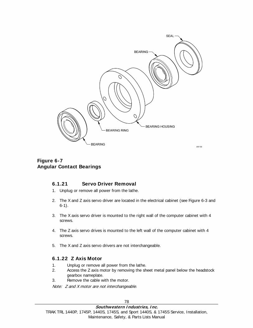
78 Southwestern Industries, Inc.
TRAK TRL 1440P, 1745P, 1440S, 1745S, and Sport 1440S, & 1745S Service, Installation, Maintenance, Safety, & Parts Lists Manual
Figure 6-7 Angular Contact Bearings
6.1.21 Servo Driver Removal 1. Unplug or remove all power from the lathe. 2. The X and Z axis servo driver are located in the electrical cabinet (see Figure 6-3 and
6-1). 3. The X axis servo driver is mounted to the right wall of the computer cabinet with 4
screws.
4. The Z axis servo drives is mounted to the left wall of the computer cabinet with 4 screws.
5. The X and Z axis servo drivers are not interchangeable.
6.1.22 Z Axis Motor 1. Unplug or remove all power from the lathe. 2. Access the Z axis motor by removing the sheet metal panel below the headstock
gearbox nameplate. 3. Remove the cable with the motor. Note: Z and X motor are not interchangeable.

79 Southwestern Industries, Inc.
TRAK TRL 1440P, 1745P, 1440S, 1745S, and Sport 1440S, & 1745S Service, Installation, Maintenance, Safety, & Parts Lists Manual
6.1.23 Z Axis Ballscrew Encoder Assembly Some machines have an encoder mounted directly on the ballscrew. Others have the encoder built into the motor. 1. Unplug or remove all power from the lathe. 2. Access the Z axis encoder assembly by removing the sheet metal panel below
the headstock gearbox nameplate. The flexible coupling at the end of the ballscrew is a component of the encoder assembly and will remain with this assembly after it is removed from the ballscrew.
This assembly is only available as a complete unit – do not disassemble. The X and Z encoder assemblies are not interchangeable. Note: The flexible coupling is screwed onto the end of the ballscrew then held with set screws.
6.1.24 Z Axis Ballscrew Removal (see Figure 7-5 and Figure 7-25)
1. Unplug or remove all power from the lathe.
2. The Z-axis ball screw is attached to the lathe in three places:
a. The left end where the Z-axis motor, the pulley, the clamp and the pair of angular contact bearings are mounted.
b. Behind the apron assembly where the ball nut is attached to the yoke and the oil line is located.
c. The right end where the floating bearing is located.
3. Access the left end by removing the sheet metal panel below the headstock nameplate.
4. Access the ball nut and the yoke by removing the apron assembly.
5. Access the ball screw by removing the ballscrew cover.
6.1.25 Align Z Axis Ballscrew Assembly (see Figure 7-5 and Figure 7-25)
1. Recheck machine level. Adjust as necessary.
2. Move carriage to middle of travel.
3. Loosen headstock bearing housing and mounting bracket and loosen tailstock bearing housing.
4. Snug but do not tighten the yoke mounting bolts.
5. Move the ball screw manually and move the carriage to the tail stock end.
6. Tighten the yoke to align it vertically.
7. Tighten the tailstock bearing housing.
8. Loosen the yoke and retighten to realign ball horizontally.
9. Move the carriage to the headstock using a 3/8” socket extension.

80 Southwestern Industries, Inc.
TRAK TRL 1440P, 1745P, 1440S, 1745S, and Sport 1440S, & 1745S Service, Installation, Maintenance, Safety, & Parts Lists Manual
10. Tighten the Z-axis housing.
11. Tighten the bearing housing.
12. Turn the ball screw manually with the 3/8” socket extension and move the carriage to the middle of the travel.
13. Loosen the yoke mounting bolts to readjust the apron plate after the bearings have been tightened.
14. Retighten the yoke.
15. Move the ball screw manually and move the carriage through the entire length of the Z-axis. Pay special attention to the areas near the headstock, tailstock, and in the middle of the travel. If there is any binding or rough spots, the alignment procedure must be repeated. The axis should feel equally free throughout the entire range.
16. Using a torque wrench, measure the torque to move the z-axis at each end, and in the middle of the axis travel. The torque reading should be a maximum of 10-15 in-lb.
6.1.26 Headstock Taper Adjustment The headstock may be adjusted to remove turning taper if the taper is caused by a lack of parallelism of the headstock to the bed ways. Ensure that the level of the bed is correct prior to any headstock adjustments. To adjust the headstock alignment, loosen the four socket head cap screws that attach the headstock housing to the bed. Using the adjusting screw located at the rear of the headstock, (see Figure 6-8) adjust the headstock position in the direction necessary to remove the taper. Note that the headstock will pivot about a pin located between the two front attaching screws. Tighten the attaching screws and test for taper.
6.1.27 Spindle Bearing Preload 1. Run the lathe for 10 minutes to insure the bearings are lubricated and slightly
warmed. Run the lathe at 500 RPM.
2. Stop lathe and set the gearbox in neutral between medium and high gears. Using the torque wrench, measure the spindle rolling torque. The acceptable range of
Figure 6-8 Headstock Alignment
i00488
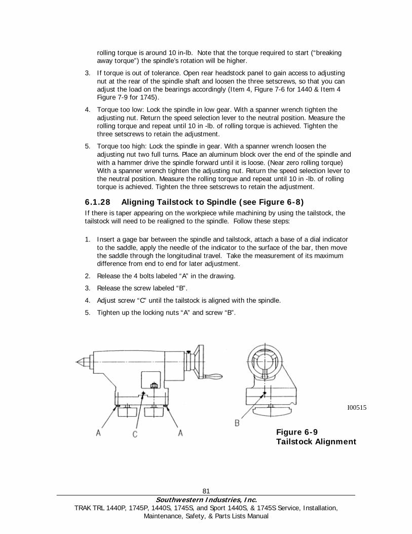
81 Southwestern Industries, Inc.
TRAK TRL 1440P, 1745P, 1440S, 1745S, and Sport 1440S, & 1745S Service, Installation, Maintenance, Safety, & Parts Lists Manual
rolling torque is around 10 in-lb. Note that the torque required to start (“breaking away torque”) the spindle’s rotation will be higher.
3. If torque is out of tolerance. Open rear headstock panel to gain access to adjusting nut at the rear of the spindle shaft and loosen the three setscrews, so that you can adjust the load on the bearings accordingly (Item 4, Figure 7-6 for 1440 & Item 4 Figure 7-9 for 1745).
4. Torque too low: Lock the spindle in low gear. With a spanner wrench tighten the adjusting nut. Return the speed selection lever to the neutral position. Measure the rolling torque and repeat until 10 in -lb. of rolling torque is achieved. Tighten the three setscrews to retain the adjustment.
5. Torque too high: Lock the spindle in gear. With a spanner wrench loosen the adjusting nut two full turns. Place an aluminum block over the end of the spindle and with a hammer drive the spindle forward until it is loose. (Near zero rolling torque) With a spanner wrench tighten the adjusting nut. Return the speed selection lever to the neutral position. Measure the rolling torque and repeat until 10 in -lb. of rolling torque is achieved. Tighten the three setscrews to retain the adjustment.
6.1.28 Aligning Tailstock to Spindle (see Figure 6-8) If there is taper appearing on the workpiece while machining by using the tailstock, the tailstock will need to be realigned to the spindle. Follow these steps: 1. Insert a gage bar between the spindle and tailstock, attach a base of a dial indicator
to the saddle, apply the needle of the indicator to the surface of the bar, then move the saddle through the longitudinal travel. Take the measurement of its maximum difference from end to end for later adjustment.
2. Release the 4 bolts labeled “A” in the drawing.
3. Release the screw labeled “B”.
4. Adjust screw “C” until the tailstock is aligned with the spindle.
5. Tighten up the locking nuts “A” and screw “B”.
Figure 6-9 Tailstock Alignment
I00515

82 Southwestern Industries, Inc.
TRAK TRL 1440P, 1745P, 1440S, 1745S, and Sport 1440S, & 1745S Service, Installation, Maintenance, Safety, & Parts Lists Manual
6.1.29 Spindle Motor Wiring (also see section 2.12) The 1440 & 1745 spindle motors are wired for 220 volts (low voltage) in the configuration. The wiring consists of 3-phase power for the motor and 110 V power for the spindle motor fan. Please see Figure 6-9 for the wiring of each motor.
Each machine does however use a different spindle motor and pulley combination.
Each junction box contains 6 terminals. The terminals should be jumpered together as shown in the figure. Connect the incoming 3-phase power to the terminals as shown below. Make sure to hook up the wires in the same terminals after the replacement motor is installed. Failure to do so may run the motor in the wrong direction.
The spindle motor fan wires are also found in the junction box. There is 1 hot wire, 1 neutral wire and 1 ground wire. The hot and neutral wires are connected as shown for each motor. It does not matter which wires are connected to the hot and neutral wires. All grounds from each cable are connected to either of the screws labeled ground.
Figure 6-10 1440/1745 Spindle Motor Wiring
6.1.30 1440/1745 Headstock Teardown
6.1.30.1 Headstock Pinions and Shaft Removal (Figures 7-6 through 7-11)
1. Remove chuck.
2. Remove headstock lid.
83 Southwestern Industries, Inc.
TRAK TRL 1440P, 1745P, 1440S, 1745S, and Sport 1440S, & 1745S Service, Installation, Maintenance, Safety, & Parts Lists Manual
3. Remove oil tray.
4. Remove item 4.
5. Loosen bolts on items 6 & 20.
6. Loosen item 32 on the threading shaft.
7. Tap item 32 to recess item 34 towards shaft to take bite off.
8. Loosen item 9 to unload spring on detent.
9. Loosen item 28.
10. Pull thread shaft assembly out with hand under item 12 to catch the ball bearings.
11. Pull the snap ring out (item 12) of the groove on the spindle shaft and move to the smaller diameter area.
12. Make sure the spindle encoder gear (item 50) and main shaft gears mesh before hitting spindle shaft, so as not to damage gears.
13. With a block of wood and mallet hit/pound spindle shaft out.
6.2 Maintenance
6.2.1 Gib Adjustments The objective of adjusting the gibs is to eliminate as much play in the table, saddle sliding surfaces as possible without having the tightness of the gib interfere with their free movement and cause a decrease in the accuracy and/or performance of the machine due to excessive friction.
6.2.1.1 Cross Slide Gib Adjustment 1. Take out yoke screws on top of cross slide.
2. Tighten gib screw and move cross slide back and forth. It should feel somewhat tight, but not to the point where it is hard to move.
3. Mount a dial indicator on the carriage and measure the slop in the cross slide. The dial indicator should be mounted a few inches in front of the tool post. (Note: this should be where the gibs are worn the worst.)
4. Try to move the cross slide back and forth to measure the amount of play. The dial indicator should only move between a 0.0002" and a 0.0005". If it moves more than this then tighten the gibs.
5. Turn the X-axis ball screw with a torque wrench and measure the torque. The torque should be less than 15 in/lb. and consistent over the travel of the X-axis. If the measurement is higher than this then loosen the gib. Make sure the cross slide is aligned properly. One easy way to check for this is to remove the yoke bolts and see if the yoke springs back into position. Misalignment is also evident if the torque is higher when the yoke is up against the rear bearing housing.
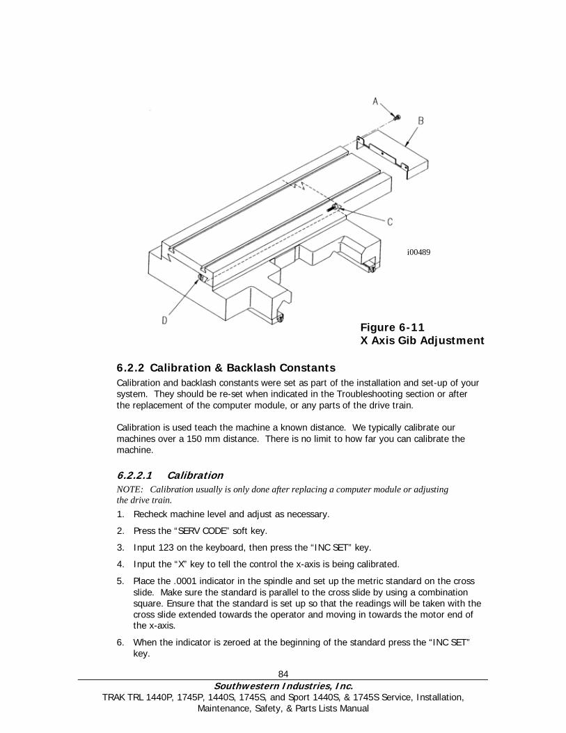
84 Southwestern Industries, Inc.
TRAK TRL 1440P, 1745P, 1440S, 1745S, and Sport 1440S, & 1745S Service, Installation, Maintenance, Safety, & Parts Lists Manual
6.2.2 Calibration & Backlash Constants Calibration and backlash constants were set as part of the installation and set-up of your system. They should be re-set when indicated in the Troubleshooting section or after the replacement of the computer module, or any parts of the drive train. Calibration is used teach the machine a known distance. We typically calibrate our machines over a 150 mm distance. There is no limit to how far you can calibrate the machine.
6.2.2.1 Calibration NOTE: Calibration usually is only done after replacing a computer module or adjusting the drive train. 1. Recheck machine level and adjust as necessary.
2. Press the “SERV CODE” soft key.
3. Input 123 on the keyboard, then press the “INC SET” key.
4. Input the “X” key to tell the control the x-axis is being calibrated.
5. Place the .0001 indicator in the spindle and set up the metric standard on the cross slide. Make sure the standard is parallel to the cross slide by using a combination square. Ensure that the standard is set up so that the readings will be taken with the cross slide extended towards the operator and moving in towards the motor end of the x-axis.
6. When the indicator is zeroed at the beginning of the standard press the “INC SET” key.
Figure 6-11 X Axis Gib Adjustment
i00489
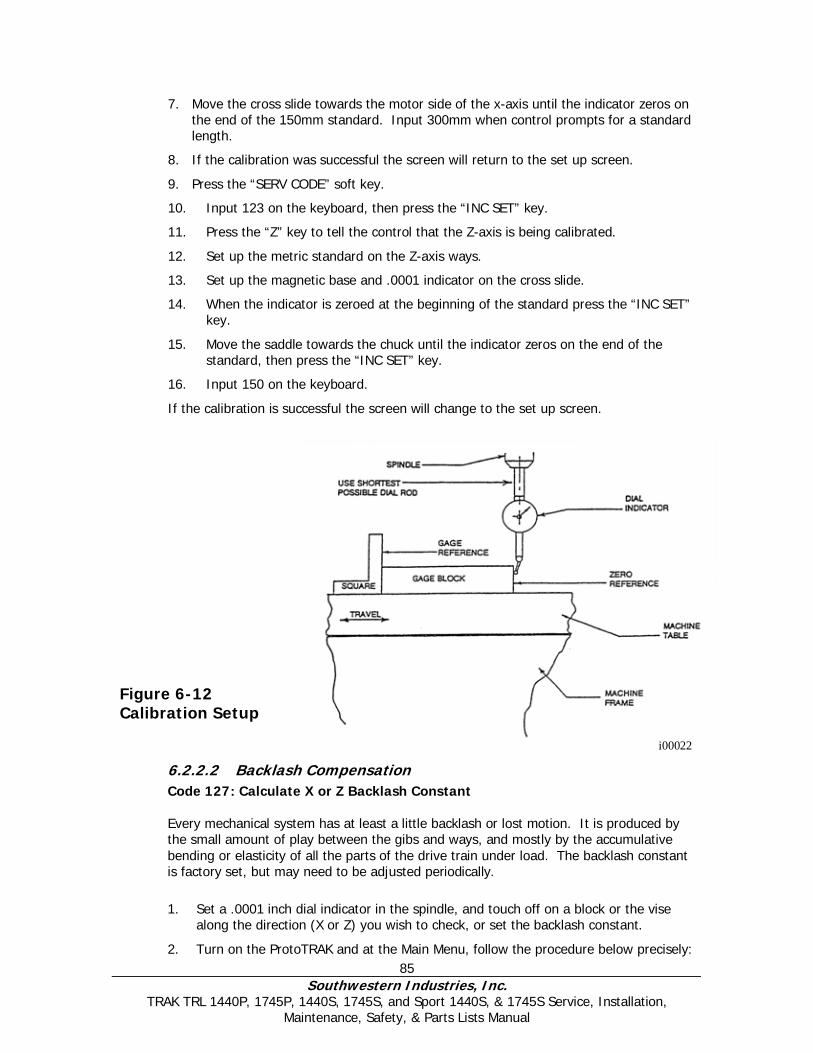
85 Southwestern Industries, Inc.
TRAK TRL 1440P, 1745P, 1440S, 1745S, and Sport 1440S, & 1745S Service, Installation, Maintenance, Safety, & Parts Lists Manual
7. Move the cross slide towards the motor side of the x-axis until the indicator zeros on the end of the 150mm standard. Input 300mm when control prompts for a standard length.
8. If the calibration was successful the screen will return to the set up screen.
9. Press the “SERV CODE” soft key.
10. Input 123 on the keyboard, then press the “INC SET” key.
11. Press the “Z” key to tell the control that the Z-axis is being calibrated.
12. Set up the metric standard on the Z-axis ways.
13. Set up the magnetic base and .0001 indicator on the cross slide.
14. When the indicator is zeroed at the beginning of the standard press the “INC SET” key.
15. Move the saddle towards the chuck until the indicator zeros on the end of the standard, then press the “INC SET” key.
16. Input 150 on the keyboard.
If the calibration is successful the screen will change to the set up screen.
Figure 6-12 Calibration Setup
6.2.2.2 Backlash Compensation
Code 127: Calculate X or Z Backlash Constant
Every mechanical system has at least a little backlash or lost motion. It is produced by the small amount of play between the gibs and ways, and mostly by the accumulative bending or elasticity of all the parts of the drive train under load. The backlash constant is factory set, but may need to be adjusted periodically. 1. Set a .0001 inch dial indicator in the spindle, and touch off on a block or the vise
along the direction (X or Z) you wish to check, or set the backlash constant.
2. Turn on the ProtoTRAK and at the Main Menu, follow the procedure below precisely:
i00022
86 Southwestern Industries, Inc.
TRAK TRL 1440P, 1745P, 1440S, 1745S, and Sport 1440S, & 1745S Service, Installation, Maintenance, Safety, & Parts Lists Manual
Conversation Says You Do a. --- a. Press MODE b. Select Mode b. Press SET UP c. Select c. Press SERV CODES d. Select d. Press “B” e. Select Code 127 e. Press X or Z f. Backlash Value = _ _ _ _ f. What is shown is the current value.
Follow the instruction on the screen and press the appropriate soft keys. Wait a few seconds between each INCR VALUE or DECR VALUE press.
g. The following is an example of what you might see when running this code.
For example, if the up and down "Oscillation Value" shown in the conversation line is .00278 inch, and the dial indicator is moving back and forth .0012, then the true backlash value is .00278 -.0012 = .00158 inch. Input this by pressing MODE, SET UP, SERV CODE, 128, SET and then .00158, SET, RETURN.
3. The X backlash identified and stored in Step 2 should be less than 0.003” on a new
machine. If it is appreciably larger, inspect the drive train for loose bolts, brackets, bearings, etc.
The backlash can also be found manually with a 0.0001” indicator with the following method.
• Load the indicator to zero from one direction and zero out the DRO.
• Move the indicator to 0.002” and then back to zero. Do not over shoot 0, otherwise start over.
• Whatever number appears on the screen is the backlash value.
• Enter this value into service code 128.
• After entering this number redo the process. The DRO and indicator should now both read 0.
CODE 128: Input Backlash Constant Code 128 allows you to enter the backlash values for each axis. It displays the value after it is entered. Be sure not to enter too much backlash on any given axis. Too much backlash in the system may cause bi-directional repeatability problems or axis motor searching.
6.2.3 Lubrication
6.2.3.1 Headstock Lubrication An oil pump provides lubrication for an even distribution of oil to all the gears and bearings in the headstock. One of the oil lines pumps oil to a site glass located on the headstock. Periodically check to see that oil is flowing. The plug to drain the headstock is located under the spindle cover towards the bottom of the casting. See Figure 6-12. Oil can be added to the reservoir by a plug in the top of the headstock cover or by removing the cover and pouring it into the headstock. There is a level
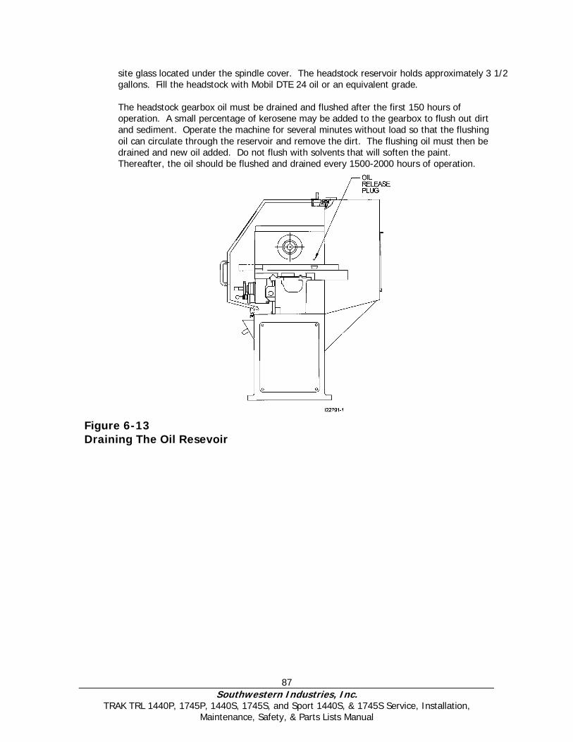
87 Southwestern Industries, Inc.
TRAK TRL 1440P, 1745P, 1440S, 1745S, and Sport 1440S, & 1745S Service, Installation, Maintenance, Safety, & Parts Lists Manual
site glass located under the spindle cover. The headstock reservoir holds approximately 3 1/2 gallons. Fill the headstock with Mobil DTE 24 oil or an equivalent grade. The headstock gearbox oil must be drained and flushed after the first 150 hours of operation. A small percentage of kerosene may be added to the gearbox to flush out dirt and sediment. Operate the machine for several minutes without load so that the flushing oil can circulate through the reservoir and remove the dirt. The flushing oil must then be drained and new oil added. Do not flush with solvents that will soften the paint. Thereafter, the oil should be flushed and drained every 1500-2000 hours of operation.
Figure 6-13 Draining The Oil Resevoir
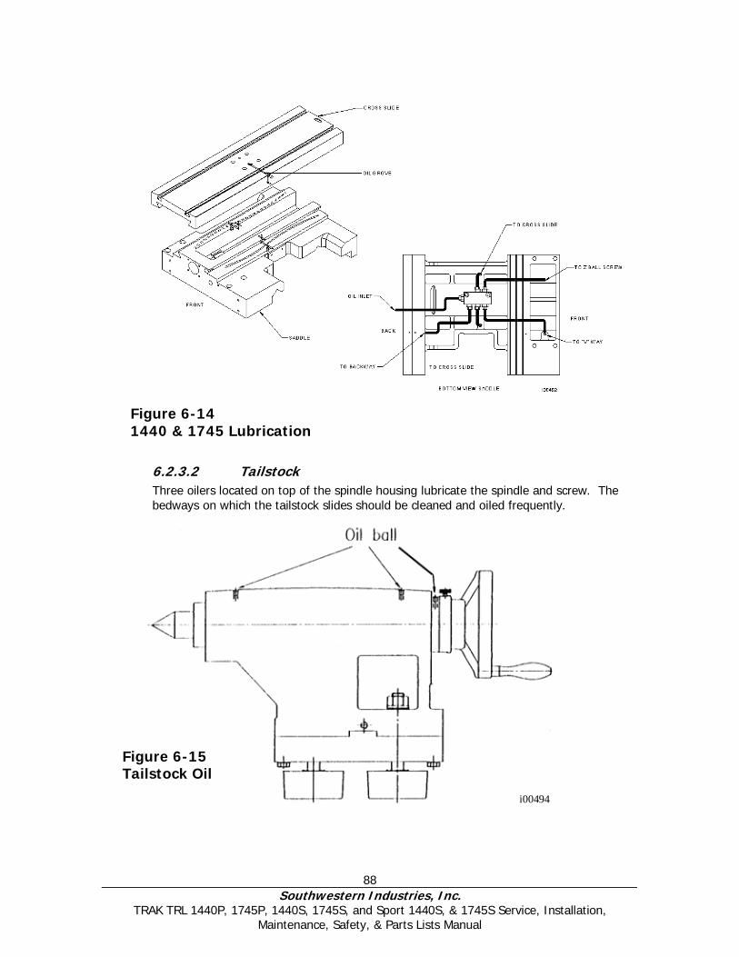
88 Southwestern Industries, Inc.
TRAK TRL 1440P, 1745P, 1440S, 1745S, and Sport 1440S, & 1745S Service, Installation, Maintenance, Safety, & Parts Lists Manual
Figure 6-14 1440 & 1745 Lubrication
6.2.3.2 Tailstock Three oilers located on top of the spindle housing lubricate the spindle and screw. The bedways on which the tailstock slides should be cleaned and oiled frequently.
Figure 6-15 Tailstock Oil
i00494
89 Southwestern Industries, Inc.
TRAK TRL 1440P, 1745P, 1440S, 1745S, and Sport 1440S, & 1745S Service, Installation, Maintenance, Safety, & Parts Lists Manual
6.2.3.3 Miscellaneous Information
For all oilers on the machine, use medium S.A.E. NO. 30 machine oil. Before filling reservoirs or oil cups, always wipe off with a clean rag any accumulation of old oil, grease or dirt that might get into a part being lubricated. Do not mix detergent type automotive oil, or multi-purpose oils with the regular grade of SAE No. 30 lubricating oil. Note: Mobil Vactra #2 oil may be used in the lube pump to lubricate the ways.
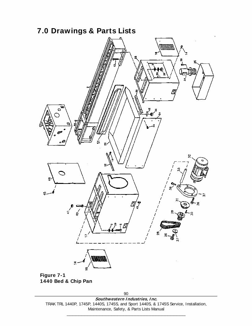
90 Southwestern Industries, Inc.
TRAK TRL 1440P, 1745P, 1440S, 1745S, and Sport 1440S, & 1745S Service, Installation, Maintenance, Safety, & Parts Lists Manual
________________________________________
7.0 Drawings & Parts Lists
Figure 7-1 1440 Bed & Chip Pan
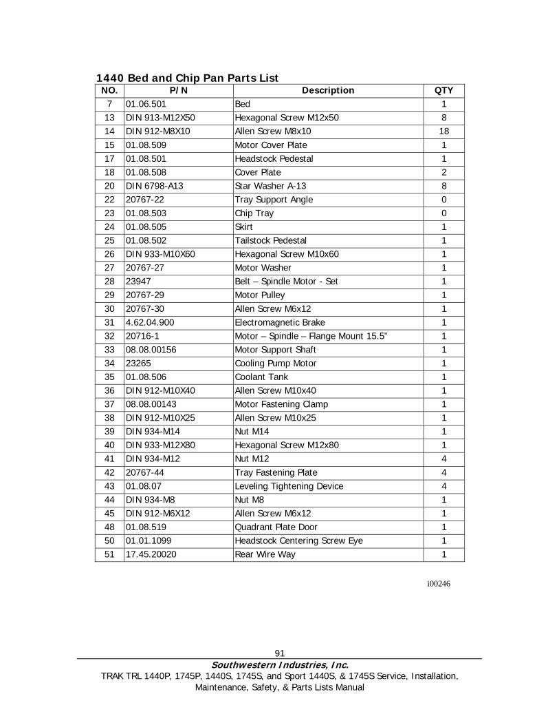
91 Southwestern Industries, Inc.
TRAK TRL 1440P, 1745P, 1440S, 1745S, and Sport 1440S, & 1745S Service, Installation, Maintenance, Safety, & Parts Lists Manual
1440 Bed and Chip Pan Parts List NO. P/N Description QTY
7 01.06.501 Bed 1 13 DIN 913-M12X50 Hexagonal Screw M12x50 8 14 DIN 912-M8X10 Allen Screw M8x10 18 15 01.08.509 Motor Cover Plate 1 17 01.08.501 Headstock Pedestal 1 18 01.08.508 Cover Plate 2 20 DIN 6798-A13 Star Washer A-13 8 22 20767-22 Tray Support Angle 0 23 01.08.503 Chip Tray 0 24 01.08.505 Skirt 1 25 01.08.502 Tailstock Pedestal 1 26 DIN 933-M10X60 Hexagonal Screw M10x60 1 27 20767-27 Motor Washer 1 28 23947 Belt – Spindle Motor - Set 1 29 20767-29 Motor Pulley 1 30 20767-30 Allen Screw M6x12 1 31 4.62.04.900 Electromagnetic Brake 1 32 20716-1 Motor – Spindle – Flange Mount 15.5” 1 33 08.08.00156 Motor Support Shaft 1 34 23265 Cooling Pump Motor 1 35 01.08.506 Coolant Tank 1 36 DIN 912-M10X40 Allen Screw M10x40 1 37 08.08.00143 Motor Fastening Clamp 1 38 DIN 912-M10X25 Allen Screw M10x25 1 39 DIN 934-M14 Nut M14 1 40 DIN 933-M12X80 Hexagonal Screw M12x80 1 41 DIN 934-M12 Nut M12 4 42 20767-44 Tray Fastening Plate 4 43 01.08.07 Leveling Tightening Device 4 44 DIN 934-M8 Nut M8 1 45 DIN 912-M6X12 Allen Screw M6x12 1 48 01.08.519 Quadrant Plate Door 1 50 01.01.1099 Headstock Centering Screw Eye 1 51 17.45.20020 Rear Wire Way 1
i00246
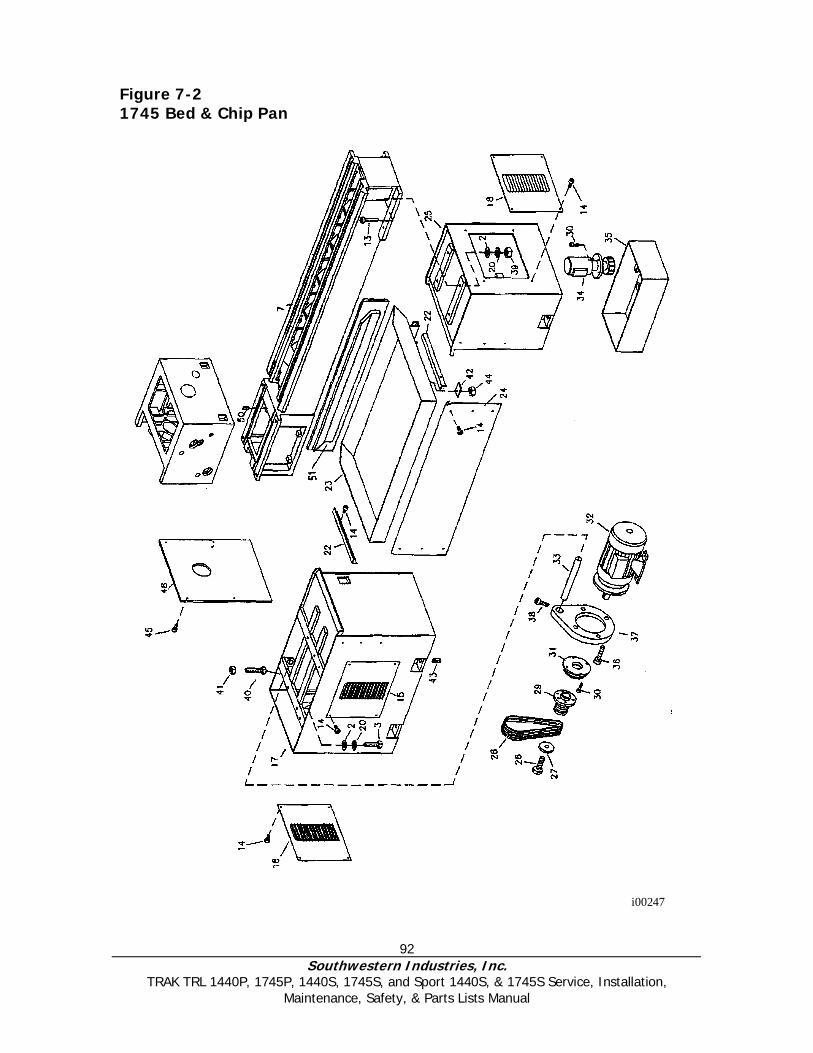
92 Southwestern Industries, Inc.
TRAK TRL 1440P, 1745P, 1440S, 1745S, and Sport 1440S, & 1745S Service, Installation, Maintenance, Safety, & Parts Lists Manual
Figure 7-2 1745 Bed & Chip Pan
i00247
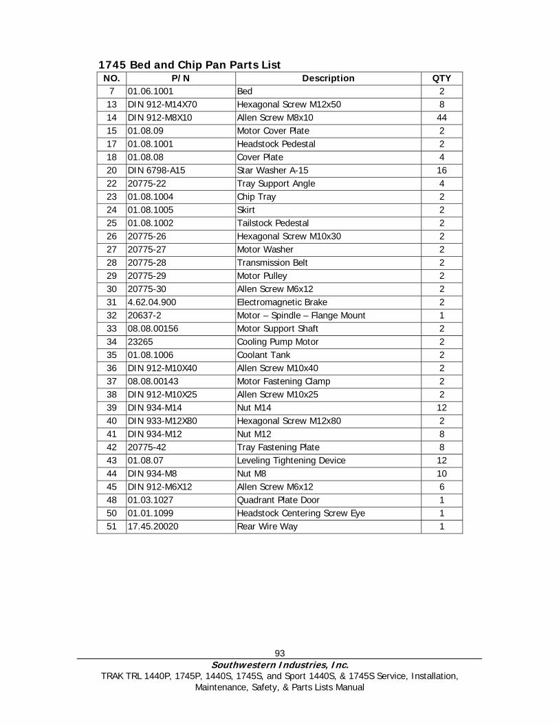
93 Southwestern Industries, Inc.
TRAK TRL 1440P, 1745P, 1440S, 1745S, and Sport 1440S, & 1745S Service, Installation, Maintenance, Safety, & Parts Lists Manual
1745 Bed and Chip Pan Parts List NO. P/N Description QTY
7 01.06.1001 Bed 2 13 DIN 912-M14X70 Hexagonal Screw M12x50 8 14 DIN 912-M8X10 Allen Screw M8x10 44 15 01.08.09 Motor Cover Plate 2 17 01.08.1001 Headstock Pedestal 2 18 01.08.08 Cover Plate 4 20 DIN 6798-A15 Star Washer A-15 16 22 20775-22 Tray Support Angle 4 23 01.08.1004 Chip Tray 2 24 01.08.1005 Skirt 2 25 01.08.1002 Tailstock Pedestal 2 26 20775-26 Hexagonal Screw M10x30 2 27 20775-27 Motor Washer 2 28 20775-28 Transmission Belt 2 29 20775-29 Motor Pulley 2 30 20775-30 Allen Screw M6x12 2 31 4.62.04.900 Electromagnetic Brake 2 32 20637-2 Motor – Spindle – Flange Mount 1 33 08.08.00156 Motor Support Shaft 2 34 23265 Cooling Pump Motor 2 35 01.08.1006 Coolant Tank 2 36 DIN 912-M10X40 Allen Screw M10x40 2 37 08.08.00143 Motor Fastening Clamp 2 38 DIN 912-M10X25 Allen Screw M10x25 2 39 DIN 934-M14 Nut M14 12 40 DIN 933-M12X80 Hexagonal Screw M12x80 2 41 DIN 934-M12 Nut M12 8 42 20775-42 Tray Fastening Plate 8 43 01.08.07 Leveling Tightening Device 12 44 DIN 934-M8 Nut M8 10 45 DIN 912-M6X12 Allen Screw M6x12 6 48 01.03.1027 Quadrant Plate Door 1 50 01.01.1099 Headstock Centering Screw Eye 1 51 17.45.20020 Rear Wire Way 1

94 Southwestern Industries, Inc.
TRAK TRL 1440P, 1745P, 1440S, 1745S, and Sport 1440S, & 1745S Service, Installation, Maintenance, Safety, & Parts Lists Manual
1440/1745 Door Interlock Assembly Parts List Item P/N Title UseAs Qty
1 22854 Cable Assy-PT3-Door Interlock Limit Switch EA 1 2 22823 Sheet Metal-PT3-Door Interlock Cam EA 0 3 22824 Mounting Base-PT3-Door Interlock EA 0 4 M5-0.8X12 25B Screw-SHCS-STL-BO EA 2 5 M6-1.0X20 27B Screw-BHCS-STL-BO EA 2 6 M6 70B Washer-Flat USS-STL-BO EA 2 7 M6 73B Washer-Split Lock-STL-BO EA 4 8 M6-1.0 50B Nut-HEX-STL-BO EA 4 9 M6-1.0X20 25B Screw-SHCS-STL-BO EA 2
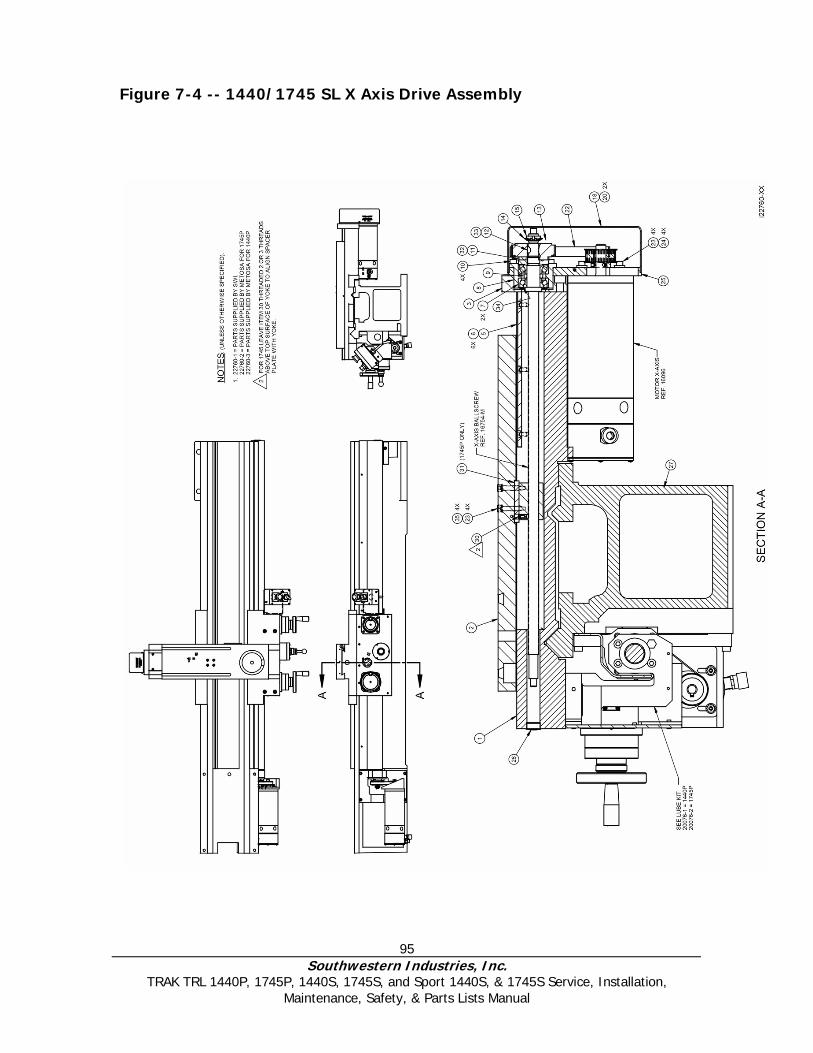
95 Southwestern Industries, Inc.
TRAK TRL 1440P, 1745P, 1440S, 1745S, and Sport 1440S, & 1745S Service, Installation, Maintenance, Safety, & Parts Lists Manual
Figure 7-4 -- 1440/1745 SL X Axis Drive Assembly
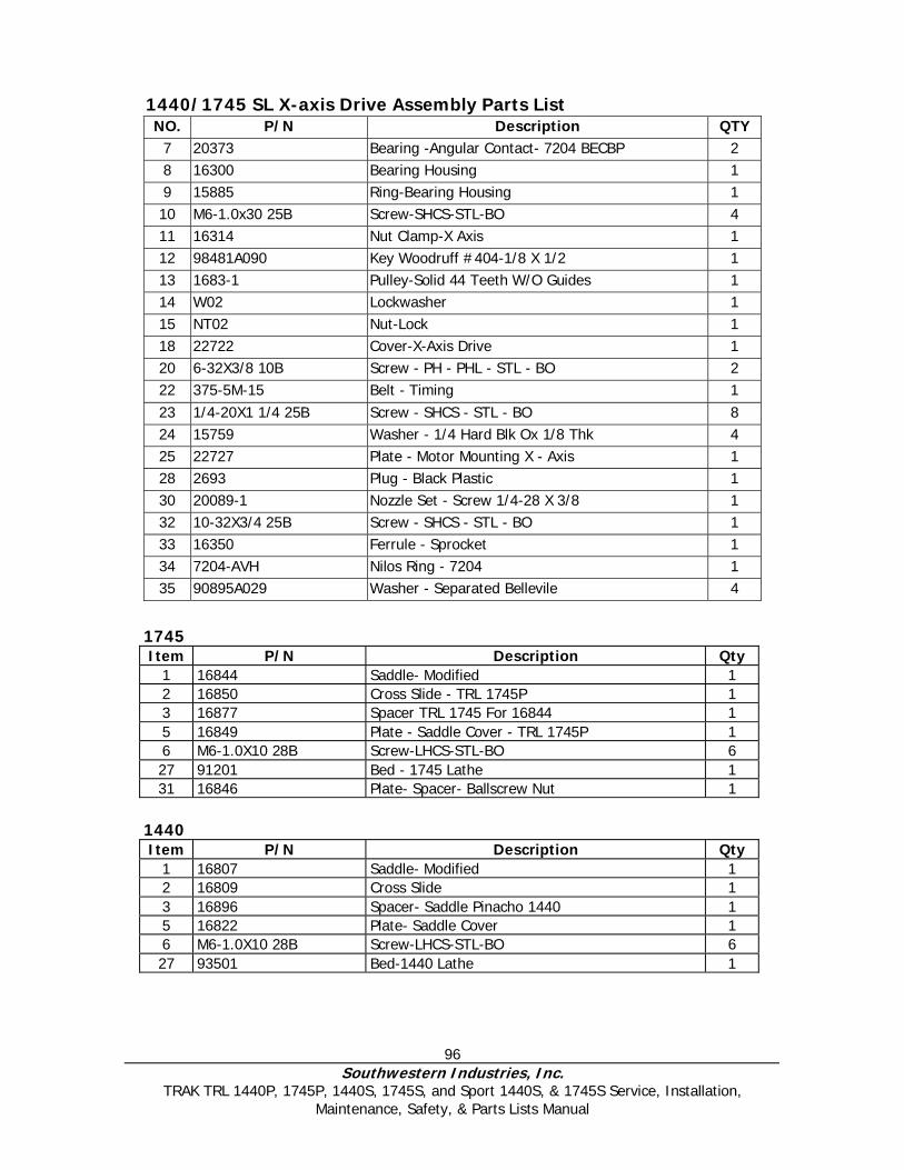
96 Southwestern Industries, Inc.
TRAK TRL 1440P, 1745P, 1440S, 1745S, and Sport 1440S, & 1745S Service, Installation, Maintenance, Safety, & Parts Lists Manual
1440/1745 SL X-axis Drive Assembly Parts List NO. P/N Description QTY
7 20373 Bearing -Angular Contact- 7204 BECBP 2 8 16300 Bearing Housing 1 9 15885 Ring-Bearing Housing 1 10 M6-1.0x30 25B Screw-SHCS-STL-BO 4 11 16314 Nut Clamp-X Axis 1 12 98481A090 Key Woodruff #404-1/8 X 1/2 1 13 1683-1 Pulley-Solid 44 Teeth W/O Guides 1 14 W02 Lockwasher 1 15 NT02 Nut-Lock 1 18 22722 Cover-X-Axis Drive 1 20 6-32X3/8 10B Screw - PH - PHL - STL - BO 2 22 375-5M-15 Belt - Timing 1 23 1/4-20X1 1/4 25B Screw - SHCS - STL - BO 8 24 15759 Washer - 1/4 Hard Blk Ox 1/8 Thk 4 25 22727 Plate - Motor Mounting X - Axis 1 28 2693 Plug - Black Plastic 1 30 20089-1 Nozzle Set - Screw 1/4-28 X 3/8 1 32 10-32X3/4 25B Screw - SHCS - STL - BO 1 33 16350 Ferrule - Sprocket 1 34 7204-AVH Nilos Ring - 7204 1 35 90895A029 Washer - Separated Bellevile 4
1745 Item P/N Description Qty
1 16844 Saddle- Modified 1 2 16850 Cross Slide - TRL 1745P 1 3 16877 Spacer TRL 1745 For 16844 1 5 16849 Plate - Saddle Cover - TRL 1745P 1 6 M6-1.0X10 28B Screw-LHCS-STL-BO 6 27 91201 Bed - 1745 Lathe 1 31 16846 Plate- Spacer- Ballscrew Nut 1
1440 Item P/N Description Qty
1 16807 Saddle- Modified 1 2 16809 Cross Slide 1 3 16896 Spacer- Saddle Pinacho 1440 1 5 16822 Plate- Saddle Cover 1 6 M6-1.0X10 28B Screw-LHCS-STL-BO 6 27 93501 Bed-1440 Lathe 1
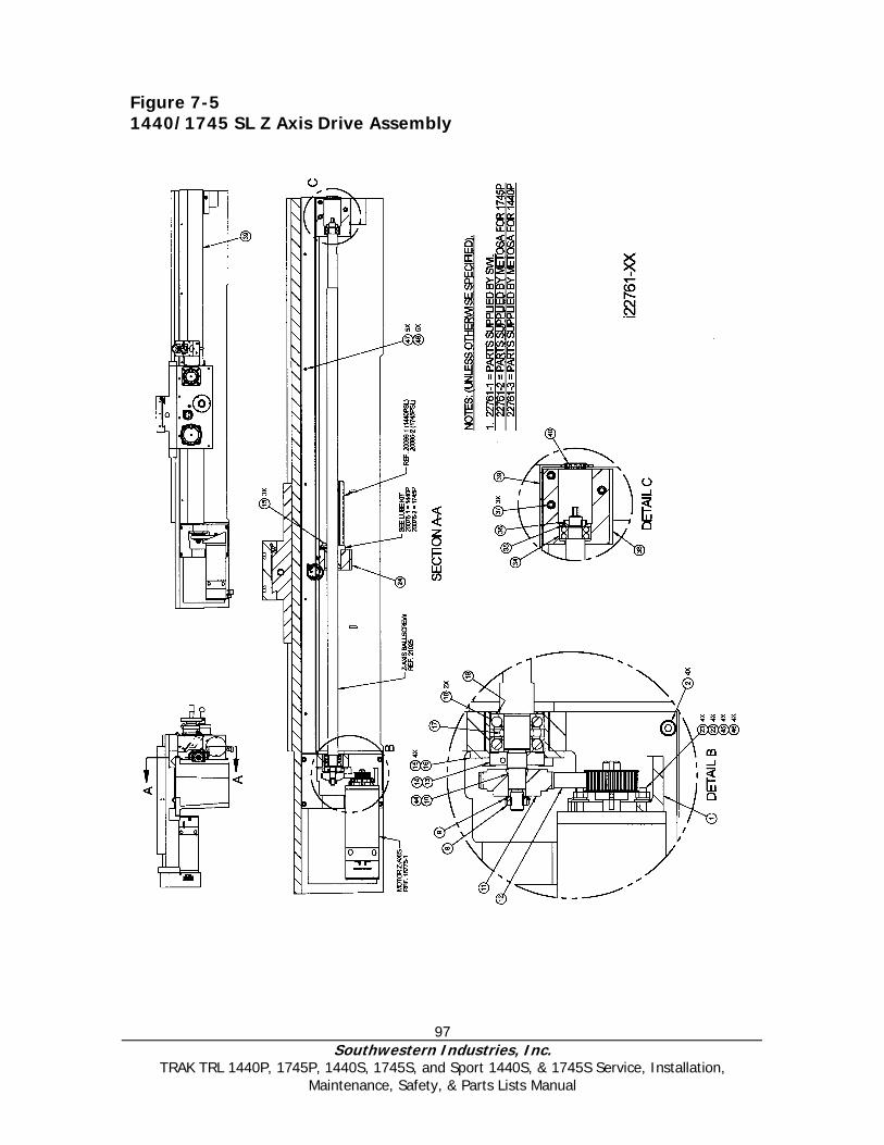
97 Southwestern Industries, Inc.
TRAK TRL 1440P, 1745P, 1440S, 1745S, and Sport 1440S, & 1745S Service, Installation, Maintenance, Safety, & Parts Lists Manual
Figure 7-5 1440/1745 SL Z Axis Drive Assembly
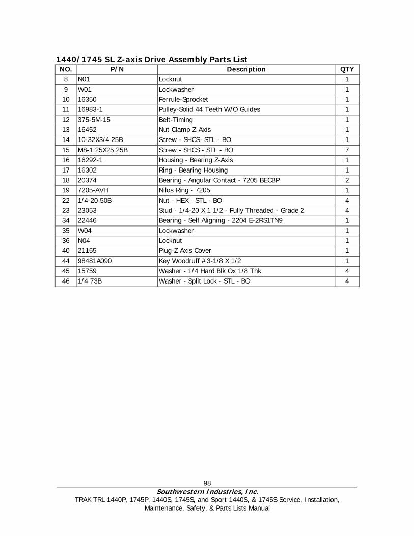
98 Southwestern Industries, Inc.
TRAK TRL 1440P, 1745P, 1440S, 1745S, and Sport 1440S, & 1745S Service, Installation, Maintenance, Safety, & Parts Lists Manual
1440/1745 SL Z-axis Drive Assembly Parts List NO. P/N Description QTY
8 N01 Locknut 1 9 W01 Lockwasher 1 10 16350 Ferrule-Sprocket 1 11 16983-1 Pulley-Solid 44 Teeth W/O Guides 1 12 375-5M-15 Belt-Timing 1 13 16452 Nut Clamp Z-Axis 1 14 10-32X3/4 25B Screw - SHCS- STL - BO 1 15 M8-1.25X25 25B Screw - SHCS - STL - BO 7 16 16292-1 Housing - Bearing Z-Axis 1 17 16302 Ring - Bearing Housing 1 18 20374 Bearing - Angular Contact - 7205 BECBP 2 19 7205-AVH Nilos Ring - 7205 1 22 1/4-20 50B Nut - HEX - STL - BO 4 23 23053 Stud - 1/4-20 X 1 1/2 - Fully Threaded - Grade 2 4 34 22446 Bearing - Self Aligning - 2204 E-2RS1TN9 1 35 W04 Lockwasher 1 36 N04 Locknut 1 40 21155 Plug-Z Axis Cover 1 44 98481A090 Key Woodruff #3-1/8 X 1/2 1 45 15759 Washer - 1/4 Hard Blk Ox 1/8 Thk 4 46 1/4 73B Washer - Split Lock - STL - BO 4
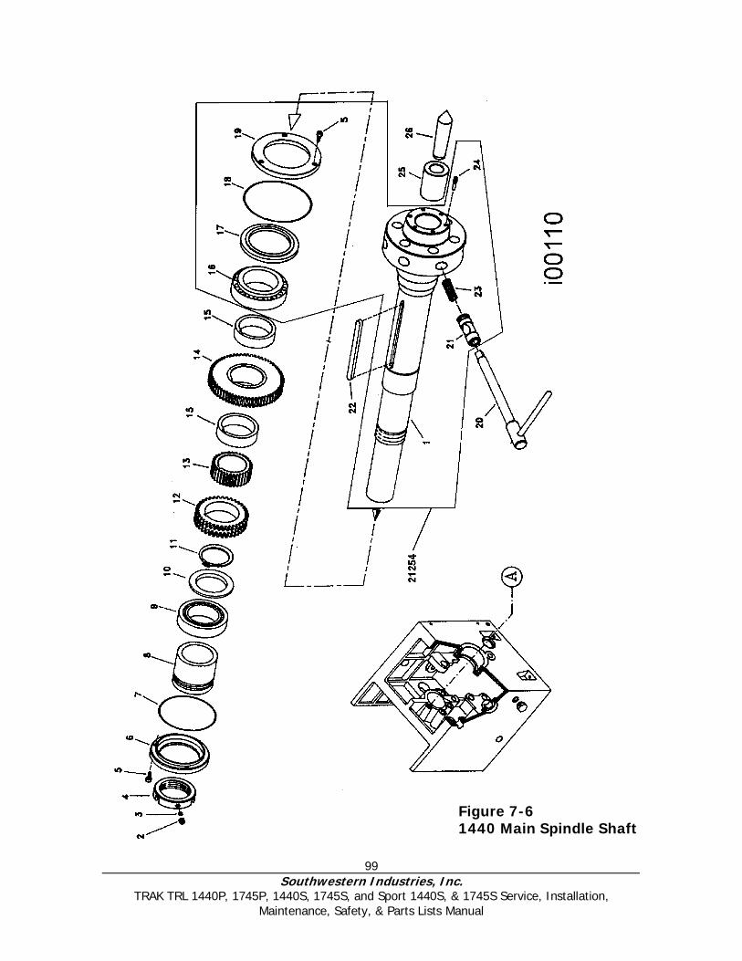
99 Southwestern Industries, Inc.
TRAK TRL 1440P, 1745P, 1440S, 1745S, and Sport 1440S, & 1745S Service, Installation, Maintenance, Safety, & Parts Lists Manual
Figure 7-6 1440 Main Spindle Shaft
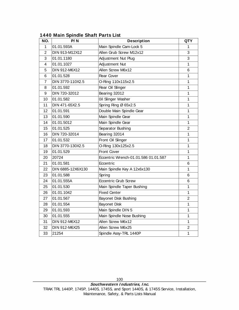
100 Southwestern Industries, Inc.
TRAK TRL 1440P, 1745P, 1440S, 1745S, and Sport 1440S, & 1745S Service, Installation, Maintenance, Safety, & Parts Lists Manual
Figure 7-7 Headstock Pinion & Shaft
1440 Main Spindle Shaft Parts List NO. P/N Description QTY
1 01.01.593A Main Spindle Cam-Lock 5 1 2 DIN 913-M12X12 Allen Grub Screw M12x12 3 3 01.01.1180 Adjustment Nut Plug 3 4 01.01.1027 Adjustment Nut 1 5 DIN 912-M6X12 Allen Screw M6x12 6 6 01.01.528 Rear Cover 1 7 DIN 3770-110X2.5 O-Ring 110x115x2.5 1 8 01.01.592 Rear Oil Slinger 1 9 DIN 720-32012 Bearing 32012 1 10 01.01.582 0il Slinger Washer 1 11 DIN 471-65X2.5 Spring Ring Ø 65x2.5 1 12 01.01.591 Double Main Spindle Gear 1 13 01.01.590 Main Spindle Gear 1 14 01.01.5012 Main Spindle Gear 1 15 01.01.525 Separator Bushing 2 16 DIN 720-32014 Bearing 32014 1 17 01.01.532 Front Oil Slinger 1 18 DIN 3770-130X2.5 O-Ring 130x125x2.5 1 19 01.01.529 Front Cover 1 20 20724 Eccentric Wrench-01.01.586 01.01.587 1 21 01.01.581 Eccentric 6 22 DIN 6885-12X6X130 Main Spindle Key A 12x6x130 1 23 01.01.588 Spring 6 24 01.01.555A Eccentric Grub Screw 6 25 01.01.530 Main Spindle Taper Bushing 1 26 01.01.1042 Fixed Center 1 27 01.01.567 Bayonet Disk Bushing 2 28 01.01.554 Bayonet Disk 1 29 01.01.593 Main Spindle DIN 5 1 30 01.01.555 Main Spindle Nose Bushing 1 31 DIN 912-M6X12 Allen Screw M6x12 1 32 DIN 912-M6X25 Allen Screw M6x25 2 33 21254 Spindle Assy-TRL 1440P 1
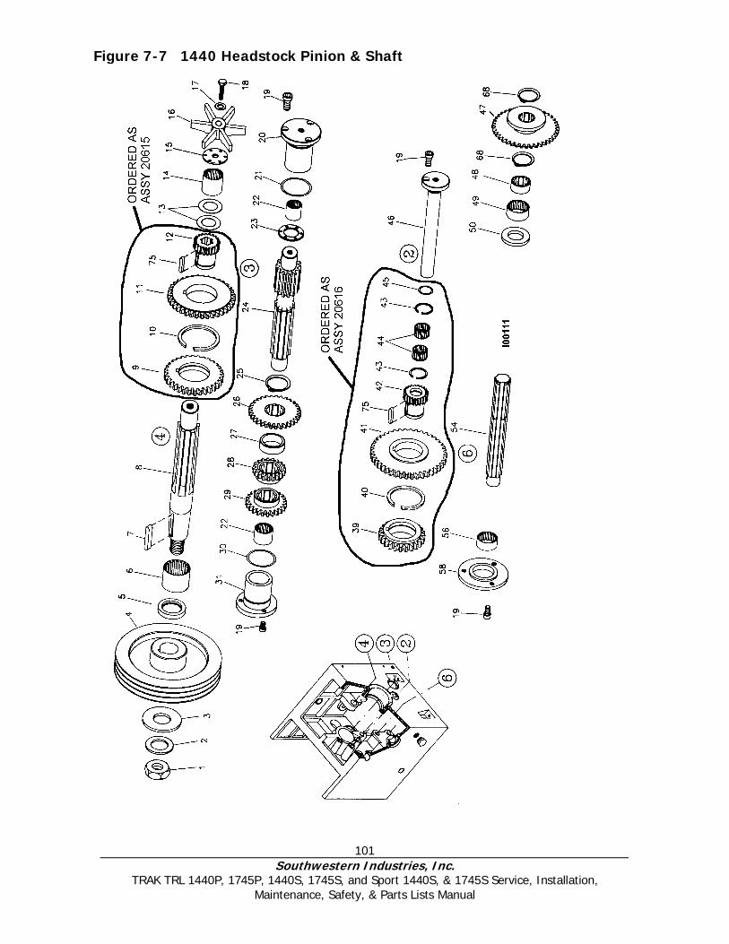
101 Southwestern Industries, Inc.
TRAK TRL 1440P, 1745P, 1440S, 1745S, and Sport 1440S, & 1745S Service, Installation, Maintenance, Safety, & Parts Lists Manual
Figure 7-7 1440 Headstock Pinion & Shaft

102 Southwestern Industries, Inc.
TRAK TRL 1440P, 1745P, 1440S, 1745S, and Sport 1440S, & 1745S Service, Installation, Maintenance, Safety, & Parts Lists Manual
1440 Headstock Pinion & Shaft Parts List NO. P/N DESCRIPTION QTY 1 DIN 934-M20 Nut M20 1 2 DIN 6798-A21 Spring Washer A-21 1 3 01.01.72 Input Shaft Wash 1 4 01.01.535 Headstock Pulley 1 5 DIN 3760-32X47X7 Retainer 32x47x7 1 6 20708 Bearing RNA 69/28 1 7 DIN 6885-8X12X42 Key A-8x12x42 1 8 01.01.501 Input Shaft 1 9 01.01.5017 Triple Gear Input Shaft 1 10 SB-45 Spring Ring SB 45 1 11 01.01.5003 Triple Gear Input Shaft 1 12 01.01.5016 Triple Gear Input Shaft 1 13 20720 Washer As 2542 2 14 20709 Bearing RNA 6904 1 15 01.01.73 Pump Washer 6 16 01.01.64 Lubrication Impeller 1 17 DIN 6798-A10.5 Elastic Washer A-10,5 1 18 DIN 933-M10X45 Hexagonal Screw M10x45 1 19 DIN 912-M6X12 Allen Screw M6x12 10 20 01.01.523 Gear Shaft Cover 1 21 DIN 3770-36X3 O-Ring 36x42x3 1 22 DIN 618-2526 Bearing HK 2526 2 23 01.01.522 Washer Shaft Gear 1 24 01.01.507 Shaft Gear 1 25 DIN 471-32X1.5 Spring Ring Ø 32x1,5 2 26 01.01.5006 Pinion Shaft Gear 1 27 01.01.520 Separator Bushing 28 01.01.5005 Pinion Shaft Gear 1 29 01.01.5004 Pinion Shaft Gear 1 30 DIN 3770-36X3 0-Ring 36x42x3 1 31 01.01.523 Pinion Shaft Cover 39 01.01.5020 Plain Shaft Triple Gear 1 40 SB-40 Spring Ring Sb 40 1 41 01.01.5009 Plain Shaft Triple Gear 1 42 01.01.5019 Plain Shaft Triple Gear 1 43 SB-27 Spring Ring SB-27 2 44 DIN 5405-20X26X20 Bearing K 20x26x20 2 45 DIN 3770-15X2.5 O-Ring 15x20x2.5 1 46 01.01.510 Plain Shaft 1 47 01.01.595 Feed Reverse Gear 1 48 01.02.531 Grooved Bushing 1 49 DIN 618-3016 Bearing HK 3016 1 50 01.01.538 Bushing 1 54 01.01.594 Grooved Shaft Feeds 1 56 20707 Bearing RNA 4904 1 58 01.01.1060 Grooved Shaft Cover Feeds 1 59 01.01.1020 Output Shaft Washer 1 75 DIN 6885-8X7X30 Key A 8x7x30 2
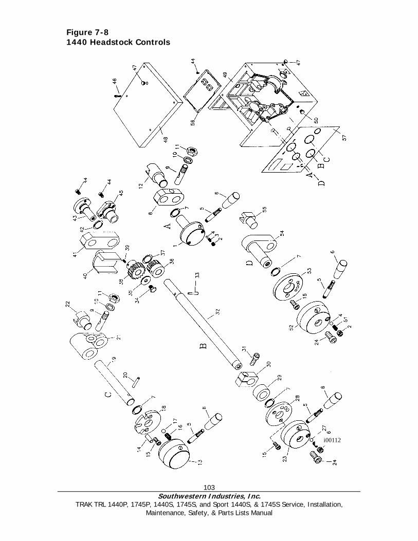
103 Southwestern Industries, Inc.
TRAK TRL 1440P, 1745P, 1440S, 1745S, and Sport 1440S, & 1745S Service, Installation, Maintenance, Safety, & Parts Lists Manual
i00112
Figure 7-8 1440 Headstock Controls

104 Southwestern Industries, Inc.
TRAK TRL 1440P, 1745P, 1440S, 1745S, and Sport 1440S, & 1745S Service, Installation, Maintenance, Safety, & Parts Lists Manual
1440 Headstock Controls Parts List NO. P/N Description QTY
1 01.01.600 Feed Reverse Control 1 2 DIN 913-M8X8 Grub Screw M8x8 3 3 01.01.1101 Spring 2 4 DIN 5401-6.35 Ball Ø 6,35 3 5 01.01.47 Handle 4 6 01.01.124 Handle Knob 4 7 DIN 3770-19X3.5 O-Ring 19x26x3,5 4 8 01.01.543 Connecting Rod 1 9 01.01.570 Pin 2 10 DIN 6798-12.5 Star Washer 12.5 2 11 DIN 934-M12 Nut M12 2 12 01.01.601 Feed Reverse Fork 1 13 01.01.551 Control 1 14 01.01.583 Tipper Screw Eye 1 15 DIN 912-M5X10 Allen Screw M5x 10 6 16 01.01.69 Spring 1 17 DIN 5401-12 Ball Ø 12 1 18 01.01.552 Control Washer 1 19 01.01.539 Control Shaft 1 20 DIN 7343-8X60 Spring Pin 8x60 1 21 01.01.41 Connecting Rod 1 22 01.01.541 Fork 1 23 01.01.546 Control 1 24 DIN 912-M10X25 Allen Screw M10x25 2 25 DIN 913-M12X12 Grub Screw M12x12 1 26 01.01.585 Spring 1 27 DIN 5401-10 Ball Ø10 1 28 01.01.561 Control Washer 1 29 01.01.1097 Separator Bushing 1 30 01.01.547 Stop Flange 1 31 DIN 912-M8X25 Allen Screw M8x25 1 32 01.01.545 Control Shaft 1 33 DIN 1-6X42 Taper Pin 6x42 1 34 DIN 933-M8X10 Hexagonal Screw M8x10 1 35 01.01.565 Washer 1 36 01.01.563 Change Pinion 1 37 DIN 3770-20X2.5 O-Ring 20x25x2,5 1 38 01.01.564 Change Pinion 1 39 DIN 913-M6X8 Grub Screw M6x8 1 40 01.01.5050 Fork 1 41 01.01.549 Connecting Rod 1 42 DIN 3770-15X2,5 O-Ring 15x20x2,5 1 43 01.01.562 Cover Shaft 1 44 DIN 912-M6X12 Allen Screw M6x12 6
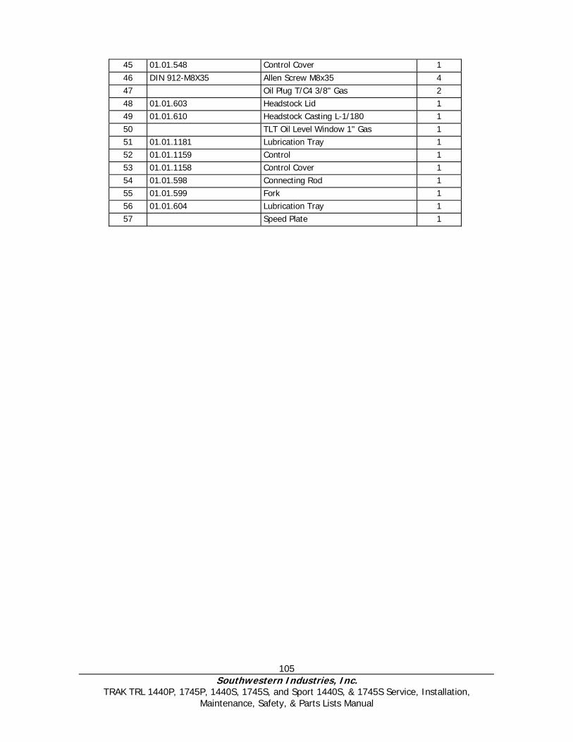
105 Southwestern Industries, Inc.
TRAK TRL 1440P, 1745P, 1440S, 1745S, and Sport 1440S, & 1745S Service, Installation, Maintenance, Safety, & Parts Lists Manual
45 01.01.548 Control Cover 1 46 DIN 912-M8X35 Allen Screw M8x35 4 47 Oil Plug T/C4 3/8" Gas 2 48 01.01.603 Headstock Lid 1 49 01.01.610 Headstock Casting L-1/180 1 50 TLT Oil Level Window 1" Gas 1 51 01.01.1181 Lubrication Tray 1 52 01.01.1159 Control 1 53 01.01.1158 Control Cover 1 54 01.01.598 Connecting Rod 1 55 01.01.599 Fork 1 56 01.01.604 Lubrication Tray 1 57 Speed Plate 1

106 Southwestern Industries, Inc.
TRAK TRL 1440P, 1745P, 1440S, 1745S, and Sport 1440S, & 1745S Service, Installation, Maintenance, Safety, & Parts Lists Manual
Figure 7-9 1745 Main Spindle Assembly
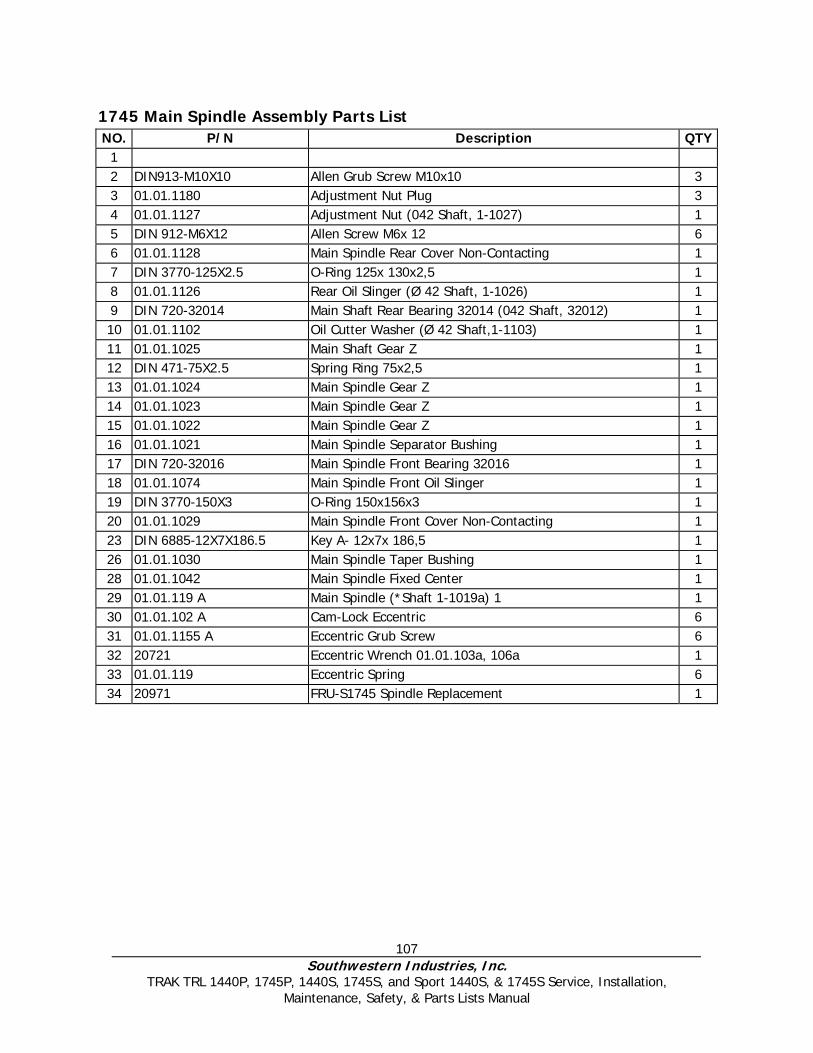
107 Southwestern Industries, Inc.
TRAK TRL 1440P, 1745P, 1440S, 1745S, and Sport 1440S, & 1745S Service, Installation, Maintenance, Safety, & Parts Lists Manual
1745 Main Spindle Assembly Parts List NO. P/N Description QTY
1 2 DIN913-M10X10 Allen Grub Screw M10x10 3 3 01.01.1180 Adjustment Nut Plug 3 4 01.01.1127 Adjustment Nut (042 Shaft, 1-1027) 1 5 DIN 912-M6X12 Allen Screw M6x 12 6 6 01.01.1128 Main Spindle Rear Cover Non-Contacting 1 7 DIN 3770-125X2.5 O-Ring 125x 130x2,5 1 8 01.01.1126 Rear Oil Slinger (Ø 42 Shaft, 1-1026) 1 9 DIN 720-32014 Main Shaft Rear Bearing 32014 (042 Shaft, 32012) 1 10 01.01.1102 Oil Cutter Washer (Ø 42 Shaft,1-1103) 1 11 01.01.1025 Main Shaft Gear Z 1 12 DIN 471-75X2.5 Spring Ring 75x2,5 1 13 01.01.1024 Main Spindle Gear Z 1 14 01.01.1023 Main Spindle Gear Z 1 15 01.01.1022 Main Spindle Gear Z 1 16 01.01.1021 Main Spindle Separator Bushing 1 17 DIN 720-32016 Main Spindle Front Bearing 32016 1 18 01.01.1074 Main Spindle Front Oil Slinger 1 19 DIN 3770-150X3 O-Ring 150x156x3 1 20 01.01.1029 Main Spindle Front Cover Non-Contacting 1 23 DIN 6885-12X7X186.5 Key A- 12x7x 186,5 1 26 01.01.1030 Main Spindle Taper Bushing 1 28 01.01.1042 Main Spindle Fixed Center 1 29 01.01.119 A Main Spindle (*Shaft 1-1019a) 1 1 30 01.01.102 A Cam-Lock Eccentric 6 31 01.01.1155 A Eccentric Grub Screw 6 32 20721 Eccentric Wrench 01.01.103a, 106a 1 33 01.01.119 Eccentric Spring 6 34 20971 FRU-S1745 Spindle Replacement 1
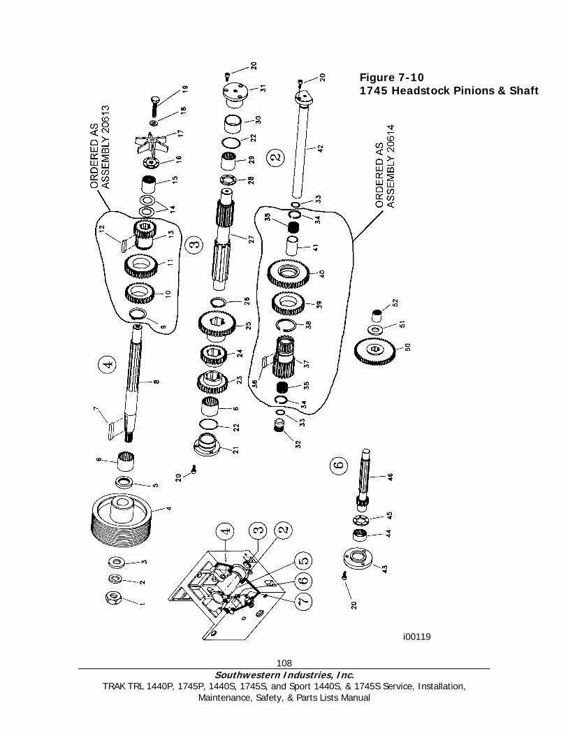
108 Southwestern Industries, Inc.
TRAK TRL 1440P, 1745P, 1440S, 1745S, and Sport 1440S, & 1745S Service, Installation, Maintenance, Safety, & Parts Lists Manual
Figure 7-10 1745 Headstock Pinions & Shaft
i00119
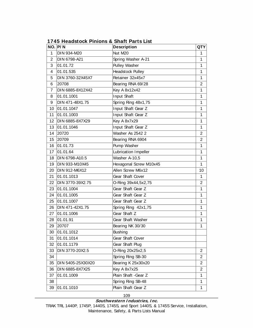
109 Southwestern Industries, Inc.
TRAK TRL 1440P, 1745P, 1440S, 1745S, and Sport 1440S, & 1745S Service, Installation, Maintenance, Safety, & Parts Lists Manual
1745 Headstock Pinions & Shaft Parts List NO. P/N Description QTY
1 DIN 934-M20 Nut M20 1 2 DIN 6798-A21 Spring Washer A-21 1 3 01.01.72 Pulley Washer 1 4 01.01.535 Headstock Pulley 1 5 DIN 3760-32X45X7 Retainer 32x45x7 1 6 20708 Bearing RNA 69/28 2 7 DIN 6885-8X12X42 Key A 8x12x42 1 8 01.01.1001 Input Shaft 1 9 DIN 471-48X1.75 Spring Ring 48x1,75 1 10 01.01.1047 Input Shaft Gear Z 1 11 01.01.1003 Input Shaft Gear Z 1 12 DIN 6885-8X7X29 Key A 8x7x29 1 13 01.01.1046 Input Shaft Gear Z 1 14 20720 Washer As 2542 2 2 15 20709 Bearing RNA 6904 2 16 01.01.73 Pump Washer 1 17 01.01.64 Lubrication Impeller 1 18 DIN 6798-A10.5 Washer A-10,5 1 19 DIN 933-M10X45 Hexagonal Screw M10x45 1 20 DIN 912-M6X12 Allen Screw M6x12 10 21 01.01.1013 Gear Shaft Cover 1 22 DIN 3770-39X2.75 O-Ring 39x44,5x2,75 2 23 01.01.1004 Gear Shaft Gear Z 1 24 01.01.1005 Gear Shaft Gear Z 1 25 01.01.1007 Gear Shaft Gear Z 1 26 DIN 471-42X1.75 Spring Ring 42x1,75 1 27 01.01.1006 Gear Shaft Z 1 28 01.01.91 Gear Shaft Washer 1 29 20707 Bearing NK 30/30 1 30 01.01.1012 Bushing 31 01.01.1014 Gear Shaft Cover 32 01.01.1179 Gear Shaft Plug 33 DIN 3770-20X2.5 O-Ring 20x25x2,5 2 34 Spring Ring SB-30 2 35 DIN 5405-25X30X20 Bearing K 25x30x20 2 36 DIN 6885-8X7X25 Key A 8x7x25 2 37 01.01.1009 Plain Shaft -Gear Z 1 38 Spring Ring SB-48 1 39 01.01.1010 Plain Shaft Gear Z 1

110 Southwestern Industries, Inc.
TRAK TRL 1440P, 1745P, 1440S, 1745S, and Sport 1440S, & 1745S Service, Installation, Maintenance, Safety, & Parts Lists Manual
40 01.01.1011 Plain Shaft Gear Z 1 41 01.01.1008 Separator Bushing 1 42 01.01.1015 Plain Shaft 1 43 01.01.1060 Gear Shaft Cover, Feeds 1 44 DIN617-4904 Bearing RNA 4904 1 45 01.01.1176 Shaft Washer, Feeds 1 46 01.01.1048 Gear Shaft, Feeds Z 1 50 01.01.1033 Headstock Feed Shaft 1 51 01.01.1177 Headstock Feed Washer 1 52 Bearing NK 20/20 2 53 20729 Cover Assy-Gear Shaft
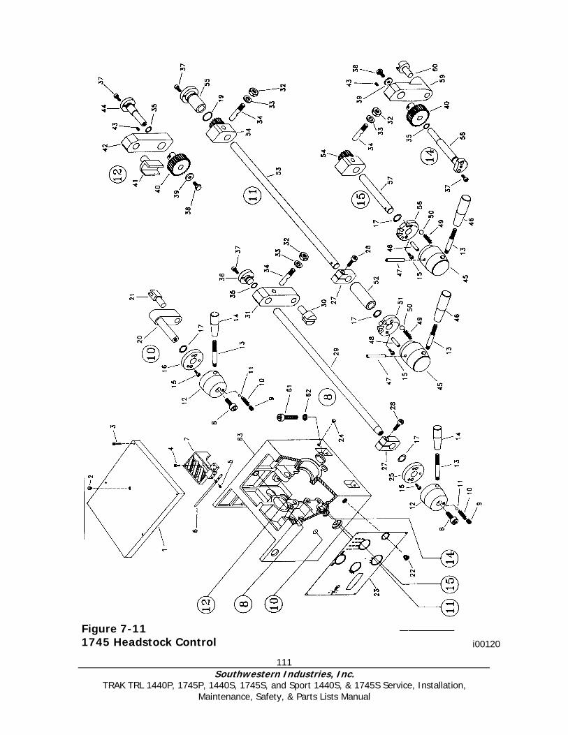
111 Southwestern Industries, Inc.
TRAK TRL 1440P, 1745P, 1440S, 1745S, and Sport 1440S, & 1745S Service, Installation, Maintenance, Safety, & Parts Lists Manual
Figure 7-11 1745 Headstock Control i00120
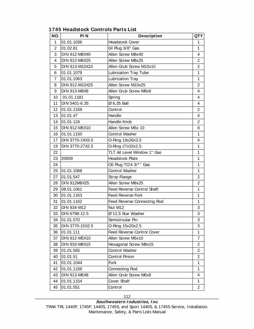
112 Southwestern Industries, Inc.
TRAK TRL 1440P, 1745P, 1440S, 1745S, and Sport 1440S, & 1745S Service, Installation, Maintenance, Safety, & Parts Lists Manual
1745 Headstock Controls Parts List NO. P/N Description QTY
1 01.01.1036 Headstock Cover 1 2 01.02.81 0il Plug 3/8" Gas 1 3 DIN 912-M8X40 Allen Screw M8x40 4 4 DIN 912-M8X25 Allen Screw M8x25 2 5 DIN 913-M10X10 Allen Grub Screw M10x10 2 6 01.01.1079 Lubrication Tray Tube 1 7 01.01.1063 Lubrication Tray 1 8 DIN 912-M10X25 Allen Screw M10x25 2 9 DIN 913-M8X8 Allen Grub Screw M8x8 4 10 01.01.1181 Spring 4 11 DIN 5401-6.35 Ø 6,35 Ball 4 12 01.01.1159 Control 2 13 01.01.47 Handle 4 14 01.01.124 Handle Knob 2 15 DIN 912-M5X10 Allen Screw M5x 10 8 16 01.01.1150 Control Washer 1 17 DIN 3770-19X3.5 O-Ring 19x26x3,5 4 19 DIN 3770-27X2.5 O-Ring 27x32x2,5 1 22 TLT Ail Level Window 1" Gas 1 23 20609 Headstock Plate 1 24 Oil Plug TC/4 3/*" Gas 1 25 01.01.1068 Control Washer 1 27 01.01.547 Strop Flange 2 28 DIN 912M8X25 Allen Screw M8x25 2 29 08.01.1061 Feed Reverse Control Shaft 1 30 01.01.1163 Feed Reverse Fork 1 31 01.01.1162 Feed Reverse Connecting Rod 1 32 DIN 934-M12 Nut M12 3 33 DIN 6798-12.5 Ø 12,5 Star Washer 3 34 01.01.570 Semicircular Pin 3 35 DIN 3770-15X2.5 O-Ring 15x20x2,5 3 36 01.01.111 Feed Reverse Control Cover 1 37 DIN 912-M5X10 Allen Screw M5x10 7 38 DIN 933-M8X15 Hexagonal Screw M8x15 2 39 01.01.565 Control Washer 2 40 01.01.51 Control Pinion 2 41 01.01.1044 Fork 1 42 01.01.1156 Connecting Rod 1 43 DIN 913-M6X8 Allen Grub Screw M6x8 4 44 01.01.1154 Cover Shaft 1 45 01.01.551 Control 2

113 Southwestern Industries, Inc.
TRAK TRL 1440P, 1745P, 1440S, 1745S, and Sport 1440S, & 1745S Service, Installation, Maintenance, Safety, & Parts Lists Manual
46 01.01.120 Handle Knob 2 47 DIN 7343-8X60 Spring Pin 8x60 2 48 01 .01.581 Sliding Screw Eye 2 49 01.01.69 Spring 2 50 DIN 5401-12 Ø 12 Ball 2 51 01.01.1151 Control Washer 1 52 01.01.1171 Separator Bushing 1 53 01.01.1150 Control Shaft 1 54 01.01.52 Change Pinion 2 55 01.01.1152 Control Cover 1 56 01.01.1167 Control Washer 1 57 01.01.1166 Control Shaft 1 58 01.01.1165 Control Shaft 1 59 01.01.1169 Connecting Rod 1 60 01.01.1045 Fork 1 61 DIN 913-M14X55 Allen Screw M14x55 2 62 01.01.1100 Washer 2 63 08.01.1059 Headstock Casting S-90/225 1

114 Southwestern Industries, Inc.
TRAK TRL 1440P, 1745P, 1440S, 1745S, and Sport 1440S, & 1745S Service, Installation, Maintenance, Safety, & Parts Lists Manual
Figure 7-12 Tailstock Assembly
i00113

115 Southwestern Industries, Inc.
TRAK TRL 1440P, 1745P, 1440S, 1745S, and Sport 1440S, & 1745S Service, Installation, Maintenance, Safety, & Parts Lists Manual
1440 Tailstock Parts List NO. P/N DESCRIPTION QTY
1 01.07.501 TAILSTOCK CASTING 1 2 01.07.502 TAILSTOCK BASE 1 2 01 07 5002 TAILSTOCK BASE L-1/180 1 3 01.07.503 ATTACHING FLANGE 1 4 01.07.528 CENTERING GIB 1 5 DIN 912-M8X20 ALLEN SCREW M8X20 2 6 01.07.520 LOCK SCREW 1 6 01.07.5020 LOCK SCREW L- 1/180 1 7 01.07.522 LOCK NUT 1 8 DIN 914-M10X30 CENTERING GRUB SCREW M10X30 2 9 DIN 914 ATTACHMENT GRUB SCREW 2 10 01.07.516 SHANK KEY 1 11 01.07.530 DEAD CENTER 1 12 01.07.504 TAILSTOCK BARREL 1 13 01.07.505 BARREL NUT 1 13 01.07.505A BARREL NUT VERSION TPI 1 14 DIN 933-M6X20 HEXAGONAL SCREW M6X20 3 15 01.07.506 TAILSTOCK SCREW 1 15 01.07.506A SCREW VERSION TPI 1 16 DIN 5405-1528 AXIAL BEARING ASK 1528 1 17 01.07.507 SCREW SUPPORT 1 18 20713 Ø 6 BALL OILER 1 19 DIN 912-M6X15 ALLEN SCREW M6X15 4 20 DIN 5405-2035 AXIAL BEARING AXK 2035 1 21 DIN 7343-4X15 SPRING PIN 4X15 3 22 01.07.509 WHEEL BUSHING 1 23 01.05.60 STRIP SPRING 4/8 24 01.07.508 VERNIER 1 24 01.07.508A VERNIER VERSION TPI 1 25 01.07.510 TAILSTOCK HANDWHEEL 1 26 01.04.20 WHEEL HANDLE 1 27 DIN 7343-6X45 SPRING PIN 6X45 1 28 01.07.517 TIGHTENING ECCENTRIC 1 29 DIN 471 1 30 20713 Ø 6 BALL OILER 5 31 01.07.518 CLAMPING SHAFT HANDLE 1 32 01.07.511 BARREL LOCK SCREW 1 33 01.07.512 BARREL LOCK BUSHING 1 34 01.07.513 BARREL LOCK BUSHING 1 35 01.07.514 BARREL LOCK KNOB 1 36 01.01.47 BARREL LOCK HANDLE 1 37 01.01.124 HANDLE KNOB 1
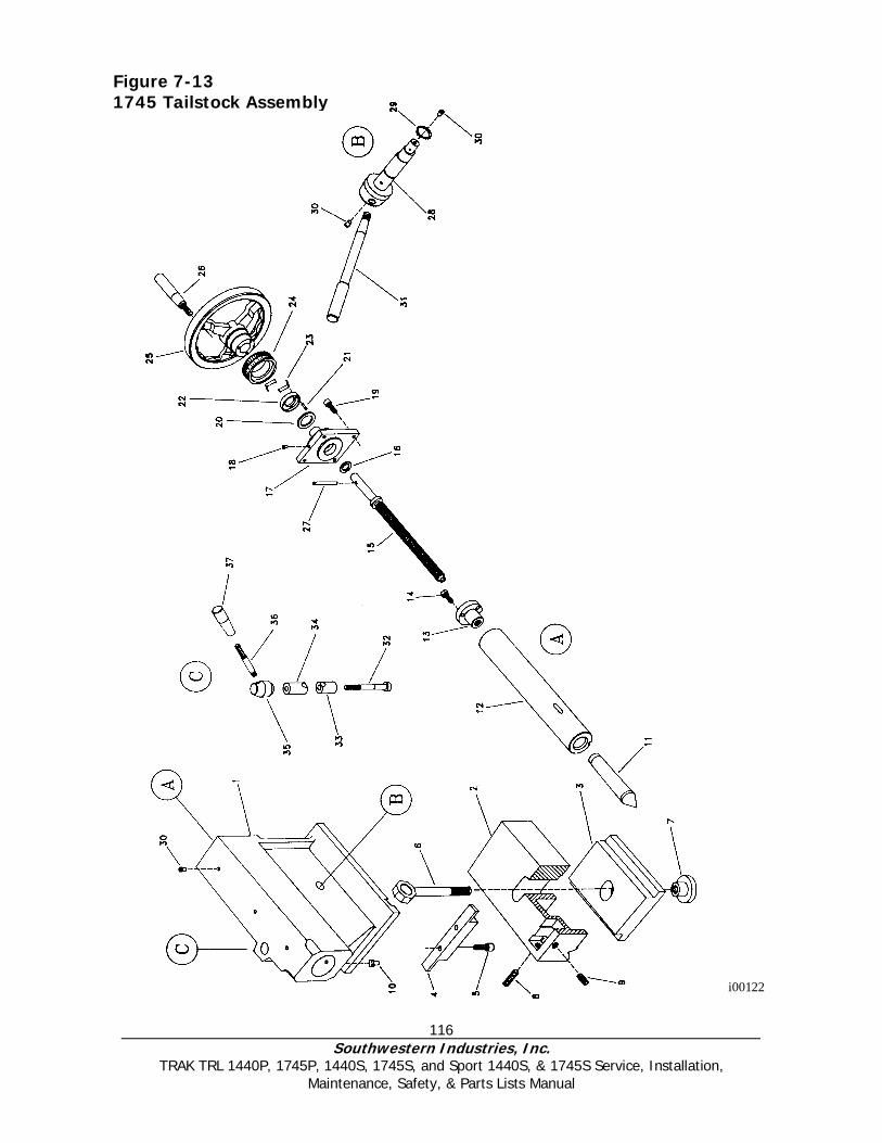
116 Southwestern Industries, Inc.
TRAK TRL 1440P, 1745P, 1440S, 1745S, and Sport 1440S, & 1745S Service, Installation, Maintenance, Safety, & Parts Lists Manual
i00122
Figure 7-13 1745 Tailstock Assembly

117 Southwestern Industries, Inc.
TRAK TRL 1440P, 1745P, 1440S, 1745S, and Sport 1440S, & 1745S Service, Installation, Maintenance, Safety, & Parts Lists Manual
1745 Tailstock Assembly Parts List NO. P/N Description QTY
1 01.07.1001 Tailstock Casting 1 2 Tailstock 1 3 01.07.1003 Attaching Flange 1 4 01.07.1028 Centering Gib 1 5 DIN 912-M10X25 Allen Screw M10x25 2 6 Lock Screw 1 7 01.07.1022 Lock Nut 1 8 DIN 914-M12X35 Centering Grub Screw M12x35 2 9 DIN 914-M12X20 Attachment Grub Screw M12x20 2 10 01.07.1016 Shank Key 1 11 01.07.1030 Dead Center 1 12 01.07.1004 Tailstock Barrel 1 13 01.07.1005 Barrel Nut 1 14 DIN 933-M8X20 Hexagonal Screw M8x20 3 15 01.07.1006 Tailstock Screw 1 16 DIN 5405-1730 Bearing Ask 1730 1 17 01.07.1007 Screw Support 1 18 20704 Ø 8 Ball Oiler 1 19 DIN 912-M8X20 Allen Screw M8x20 4 20 DIN 5405-2542 Bearing AXK 2542 1 21 DIN 7343-4X15 Spring Pin Ø 4x 15 3 22 01.07.1009 Vernier Washer 1 23 01.05.60 Strip Spring 4/8 24 01.07.1008 Vernier 1 25 01.07.1010 Handwheel 1 26 01.04.20 Wheel Handle 1 27 DIN 7343-6X50 Spring Pin Ø 6x50 1 28 01.07.1017 Clamping Shaft 1 29 DIN 471-30X1.5 Spring Ring 30x1,5 1 30 20704 Ø 8 Ball Oiler 5 31 01.07.1018 T.S. Clamp Handle 1 32 01.07.1011 Barrel Lock Screw 1 33 01.07.1012 Barrel Lock Bushing 1 34 01.07.1013 Barrel Lock Bushing 1 35 01.07.1014 Barrel Lock Knob 1 36 01.01.47 Barrel Lock Handle 1 37 01.01.124 Handle Knob 1 38 01.07.1042 Double Vernier Wheel Bushing 1
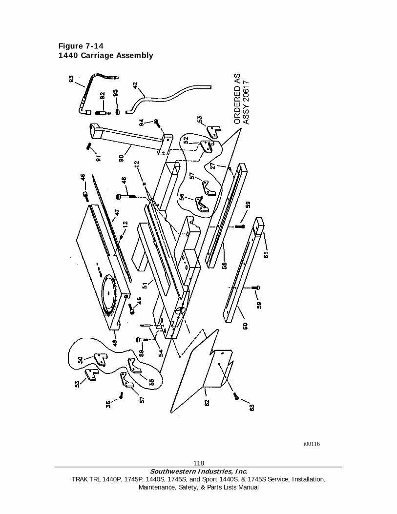
118 Southwestern Industries, Inc.
TRAK TRL 1440P, 1745P, 1440S, 1745S, and Sport 1440S, & 1745S Service, Installation, Maintenance, Safety, & Parts Lists Manual
Figure 7-14 1440 Carriage Assembly
i00116

119 Southwestern Industries, Inc.
TRAK TRL 1440P, 1745P, 1440S, 1745S, and Sport 1440S, & 1745S Service, Installation, Maintenance, Safety, & Parts Lists Manual
1440 and 1745 Carriage Assembly Parts List NO. P/N Description QTY12 Ø 8 Oiler 1 27 Ø 6 Oiler 1 36 DIN 912-M6X20 Allen Screw M6x20 1 42 20717 Coolant Hose 1 46 01.05.1061 Cross Slide Gib Tightening Screw 1 47 01.05.502 Cross Slide Adjustment Gib 1 48 DIN 912-M10X60 Allen Screw M10x60 1 49 01.05.503 Cross Slide 1 50 01.05.536 Rubber Left Flat Wiper 1 51 01.05.501 Carriage 1 52 01 05.537 Rubber Right Flat Wiper 1 53 01.05.554 Square Metal Plate 1 54 01.04.49 Milled Pin 1 55 01.05.539 Left V-Wiper 1 56 01.05.538 Right V-Wiper 1 57 01.05.553 Prism Metal Plate 1 58 01.05.526 Rear Plain Gib 1 59 DIN 931-M8X25 Hexagonal Screw M8x25 1 61 01.05.527 Saddle Lock 1 62 05.05.577 Topslide Protection 1 63 DIN 912-M6X10 Allen Screw M6x10 1 89 DIN 912-M10X50 Allen Screw M10x50 1 90 01.08.523 Coolant Nozzle Support 1 91 DIN 913-M6X8 Grub Screw M6x8 1 92 01.08.24 Coolant Raccord 1 93 20714 Coolant Nozzle 1 94 DIN 912-M6X12 Allen Screw M6x12 1 95 Clamp NPL 16/9 W1 1
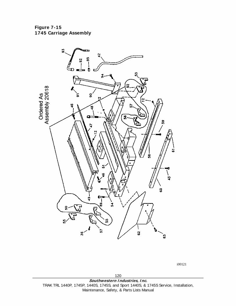
120 Southwestern Industries, Inc.
TRAK TRL 1440P, 1745P, 1440S, 1745S, and Sport 1440S, & 1745S Service, Installation, Maintenance, Safety, & Parts Lists Manual
Figure 7-15 1745 Carriage Assembly
i00121
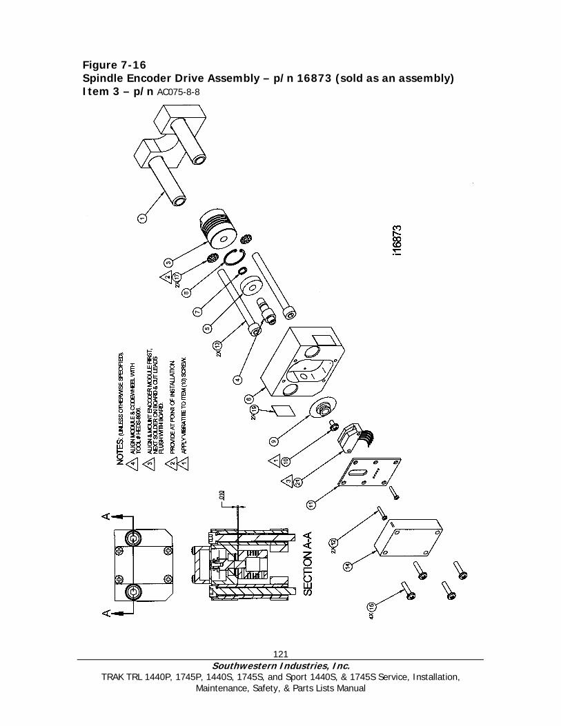
121 Southwestern Industries, Inc.
TRAK TRL 1440P, 1745P, 1440S, 1745S, and Sport 1440S, & 1745S Service, Installation, Maintenance, Safety, & Parts Lists Manual
Figure 7-16 Spindle Encoder Drive Assembly – p/n 16873 (sold as an assembly) Item 3 – p/n AC075-8-8
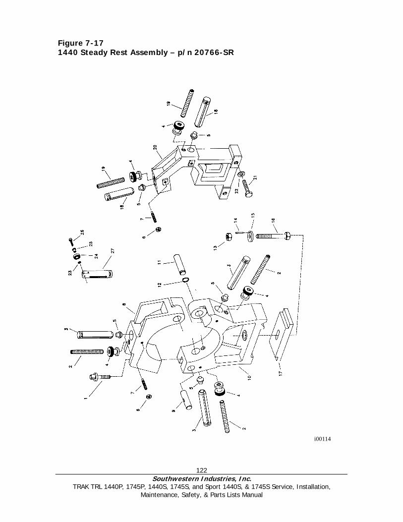
122 Southwestern Industries, Inc.
TRAK TRL 1440P, 1745P, 1440S, 1745S, and Sport 1440S, & 1745S Service, Installation, Maintenance, Safety, & Parts Lists Manual
Figure 7-17 1440 Steady Rest Assembly – p/n 20766-SR
i00114
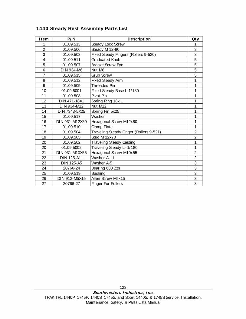
123 Southwestern Industries, Inc.
TRAK TRL 1440P, 1745P, 1440S, 1745S, and Sport 1440S, & 1745S Service, Installation, Maintenance, Safety, & Parts Lists Manual
1440 Steady Rest Assembly Parts List
Item P/N Description Qty 1 01.09.513 Steady Lock Screw 1 2 01.09.506 Steady M 12-90 3 3 01.09.503 Fixed Steady Fingers (Rollers 9-520) 3 4 01.09.511 Graduated Knob 5 5 01.09.507 Bronze Screw Eye 5 6 DIN 934-M6 Nut M6 5 7 01.09.515 Grub Screw 5 8 01.09.512 Fixed Steady Arm 1 9 01.09.509 Threaded Pin 1 10 01.09.5001 Fixed Steady Base L-1/180 1 11 01.09.508 Pivot Pin 1 12 DIN 471-18X1 Spring Ring 18x 1 1 13 DIN 934-M12 Nut M12 1 14 DIN 7343-5X25 Spring Pin 5x25 1 15 01.09.517 Washer 1 16 DIN 931-M12X80 Hexagonal Screw M12x80 1 17 01.09.510 Clamp Plate 1 18 01.09.504 Traveling Steady Finger (Rollers 9-521) 2 19 01.09.505 Stud M 12x70 2 20 01.09.502 Traveling Steady Casting 1 20 01.09.5002 Traveling Steady L- 1/180 1 21 DIN 931-M10X55 Hexagonal Screw M10x55 2 22 DIN 125-A11 Washer A-11 2 23 DIN 125-A5 Washer A-5 3 24 20766-24 Bearing 688 Zzs 3 25 01.09.519 Bushing 3 26 DIN 912-M5X15 Allen Screw M5x15 3 27 20766-27 Finger For Rollers 3
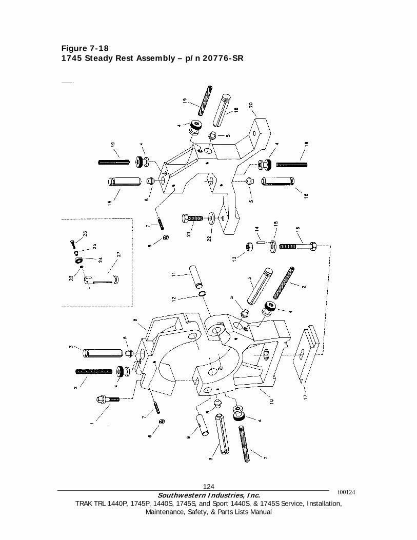
124 Southwestern Industries, Inc.
TRAK TRL 1440P, 1745P, 1440S, 1745S, and Sport 1440S, & 1745S Service, Installation, Maintenance, Safety, & Parts Lists Manual
Figure 7-18 1745 Steady Rest Assembly – p/n 20776-SR
i00124
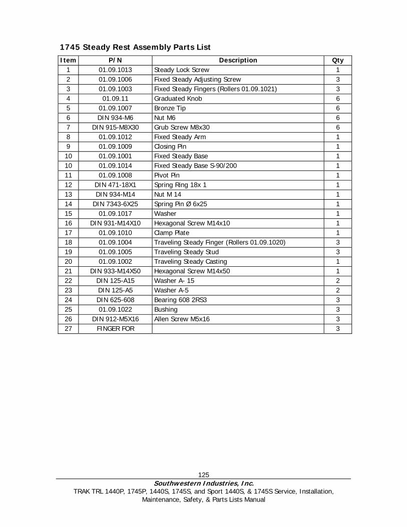
125 Southwestern Industries, Inc.
TRAK TRL 1440P, 1745P, 1440S, 1745S, and Sport 1440S, & 1745S Service, Installation, Maintenance, Safety, & Parts Lists Manual
1745 Steady Rest Assembly Parts List Item P/N Description Qty
1 01.09.1013 Steady Lock Screw 1 2 01.09.1006 Fixed Steady Adjusting Screw 3 3 01.09.1003 Fixed Steady Fingers (Rollers 01.09.1021) 3 4 01.09.11 Graduated Knob 6 5 01.09.1007 Bronze Tip 6 6 DIN 934-M6 Nut M6 6 7 DIN 915-M8X30 Grub Screw M8x30 6 8 01.09.1012 Fixed Steady Arm 1 9 01.09.1009 Closing Pin 1 10 01.09.1001 Fixed Steady Base 1 10 01.09.1014 Fixed Steady Base S-90/200 1 11 01.09.1008 Pivot Pin 1 12 DIN 471-18X1 Spring Ring 18x 1 1 13 DIN 934-M14 Nut M 14 1 14 DIN 7343-6X25 Spring Pin Ø 6x25 1 15 01.09.1017 Washer 1 16 DIN 931-M14X10 Hexagonal Screw M14x10 1 17 01.09.1010 Clamp Plate 1 18 01.09.1004 Traveling Steady Finger (Rollers 01.09.1020) 3 19 01.09.1005 Traveling Steady Stud 3 20 01.09.1002 Traveling Steady Casting 1 21 DIN 933-M14X50 Hexagonal Screw M14x50 1 22 DIN 125-A15 Washer A- 15 2 23 DIN 125-A5 Washer A-5 2 24 DIN 625-608 Bearing 608 2RS3 3 25 01.09.1022 Bushing 3 26 DIN 912-M5X16 Allen Screw M5x16 3 27 FINGER FOR 3
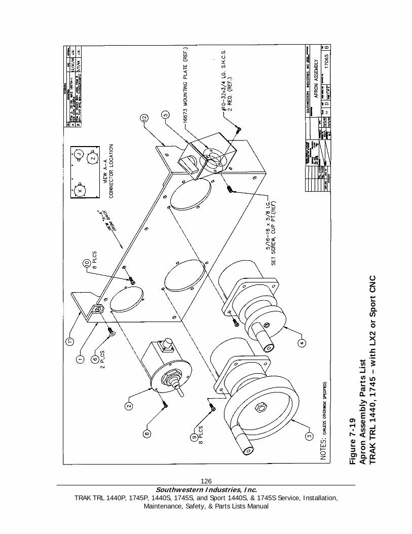
126 Southwestern Industries, Inc.
TRAK TRL 1440P, 1745P, 1440S, 1745S, and Sport 1440S, & 1745S Service, Installation, Maintenance, Safety, & Parts Lists Manual
Fig
ure
7-1
9
Ap
ron
Ass
emb
ly P
arts
Lis
t TR
AK
TR
L 14
40
, 17
45
– w
ith
LX
2 o
r Sp
ort
CN
C
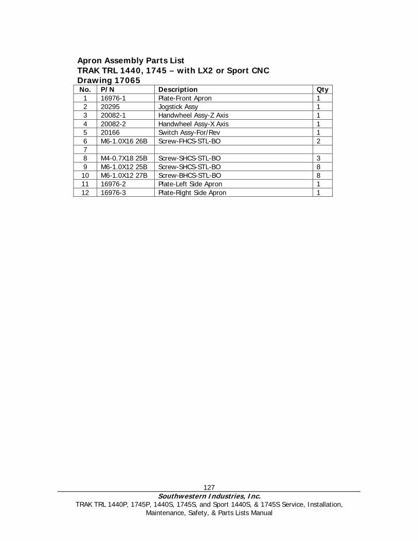
127 Southwestern Industries, Inc.
TRAK TRL 1440P, 1745P, 1440S, 1745S, and Sport 1440S, & 1745S Service, Installation, Maintenance, Safety, & Parts Lists Manual
Apron Assembly Parts List TRAK TRL 1440, 1745 – with LX2 or Sport CNC Drawing 17065 No. P/N Description Qty 1 16976-1 Plate-Front Apron 1 2 20295 Jogstick Assy 1 3 20082-1 Handwheel Assy-Z Axis 1 4 20082-2 Handwheel Assy-X Axis 1 5 20166 Switch Assy-For/Rev 1 6 M6-1.0X16 26B Screw-FHCS-STL-BO 2 7 8 M4-0.7X18 25B Screw-SHCS-STL-BO 3 9 M6-1.0X12 25B Screw-SHCS-STL-BO 8 10 M6-1.0X12 27B Screw-BHCS-STL-BO 8 11 16976-2 Plate-Left Side Apron 1 12 16976-3 Plate-Right Side Apron 1
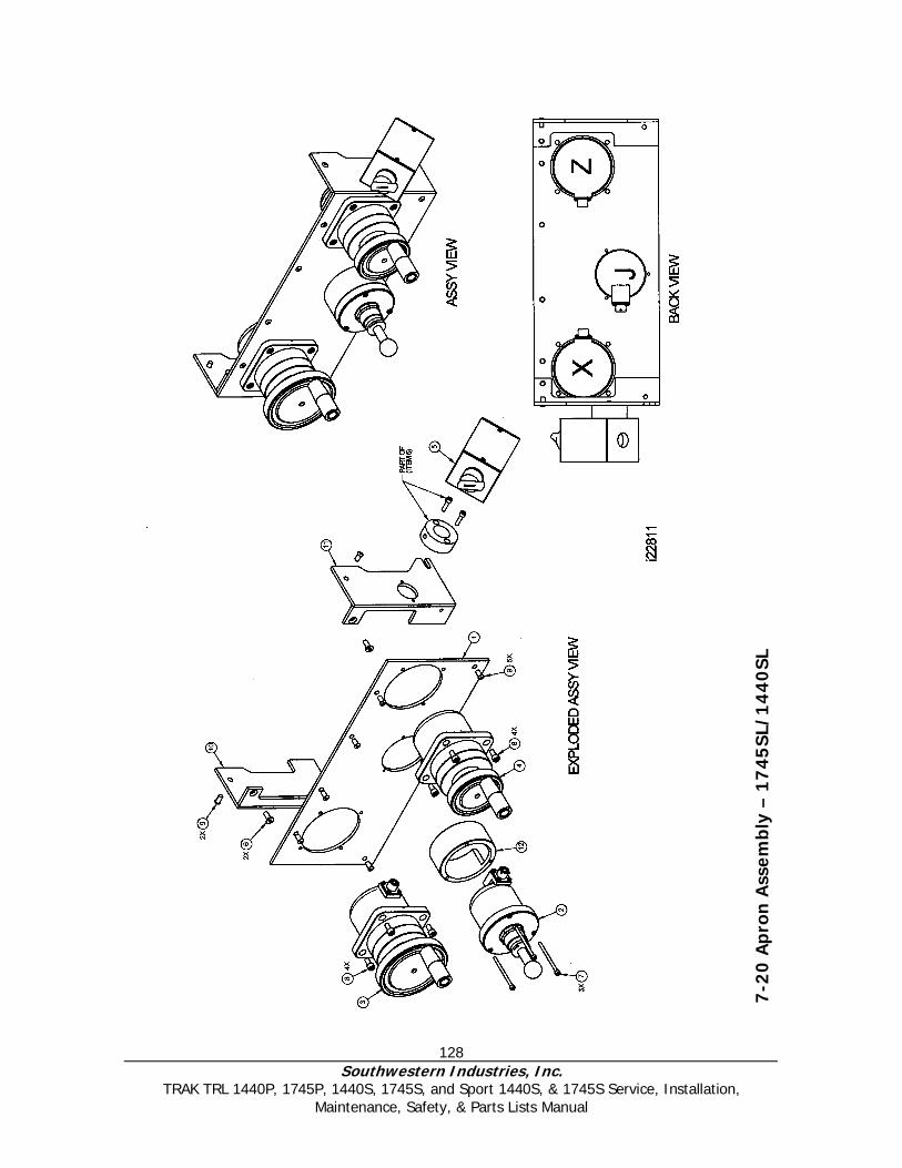
128 Southwestern Industries, Inc.
TRAK TRL 1440P, 1745P, 1440S, 1745S, and Sport 1440S, & 1745S Service, Installation, Maintenance, Safety, & Parts Lists Manual
7-2
0 A
pro
n A
ssem
bly
– 1
745
SL/
14
40
SL

129 Southwestern Industries, Inc.
TRAK TRL 1440P, 1745P, 1440S, 1745S, and Sport 1440S, & 1745S Service, Installation, Maintenance, Safety, & Parts Lists Manual
Apron Assembly Parts List – 1440 SL/1745 SL
No. P/N Description Qty 1 22723 Apron - Panel 1 2 20295 Jogstick-Assy 1 3 20082-3 Electronic Handwheel-Z-Axis TRL 1 4 20082-2 Electronic Handwheel-X-Axis TRL 1 5 22769 Forward/Reverse Switch Assy 1 6 M6-1.0X16 26B Screw-FHCS-STL-BO 2 7 M4-0.7X60 25B Screw-SHCS-STL-BO 3 8 M6-1.0X12 25B Screw-SHCS-STL-BO 8 9 M6-1.0X12 27B Screw-BHCS-STL-BO 8 12 22720 Ring - Spacer 1
i22811
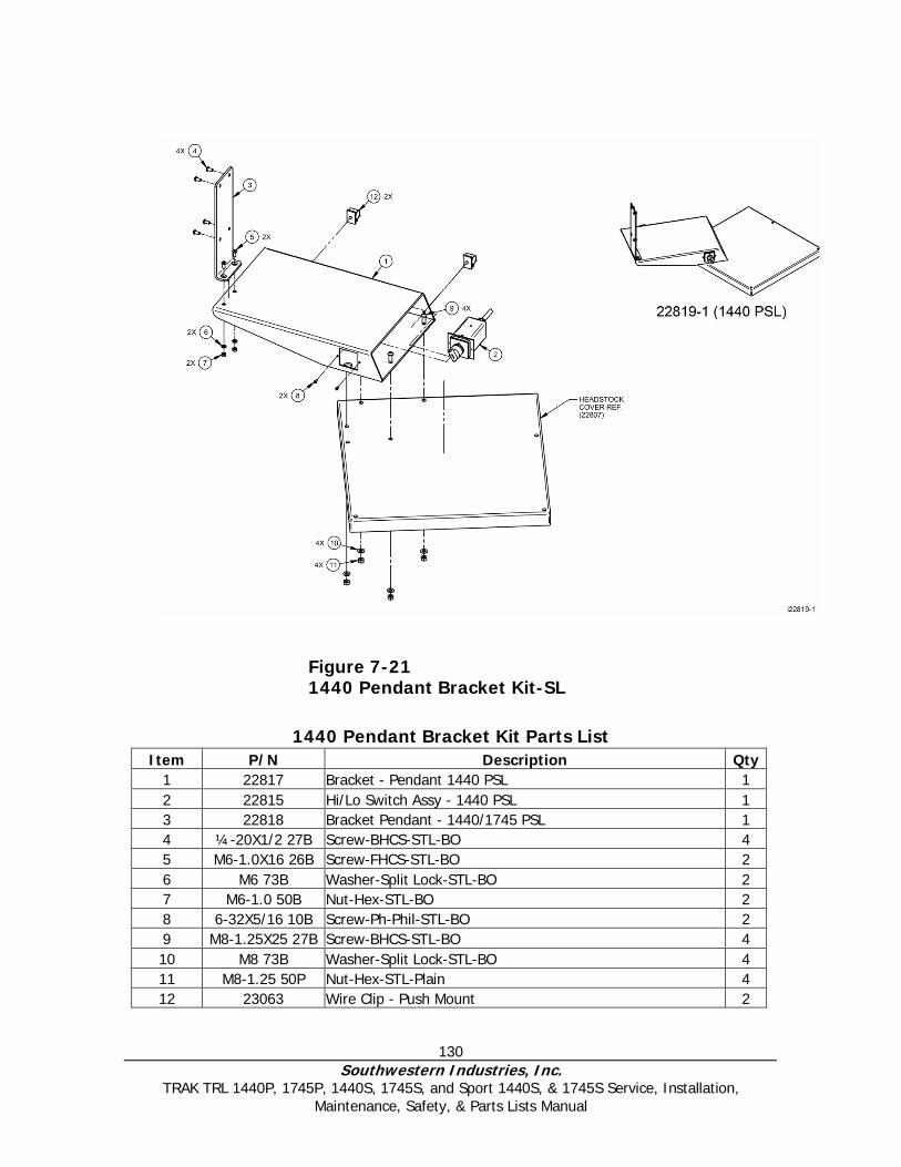
130 Southwestern Industries, Inc.
TRAK TRL 1440P, 1745P, 1440S, 1745S, and Sport 1440S, & 1745S Service, Installation, Maintenance, Safety, & Parts Lists Manual
1440 Pendant Bracket Kit Parts List Item P/N Description Qty
1 22817 Bracket - Pendant 1440 PSL 1 2 22815 Hi/Lo Switch Assy - 1440 PSL 1 3 22818 Bracket Pendant - 1440/1745 PSL 1 4 ¼-20X1/2 27B Screw-BHCS-STL-BO 4 5 M6-1.0X16 26B Screw-FHCS-STL-BO 2 6 M6 73B Washer-Split Lock-STL-BO 2 7 M6-1.0 50B Nut-Hex-STL-BO 2 8 6-32X5/16 10B Screw-Ph-Phil-STL-BO 2 9 M8-1.25X25 27B Screw-BHCS-STL-BO 4 10 M8 73B Washer-Split Lock-STL-BO 4 11 M8-1.25 50P Nut-Hex-STL-Plain 4 12 23063 Wire Clip - Push Mount 2
Figure 7-21 1440 Pendant Bracket Kit-SL
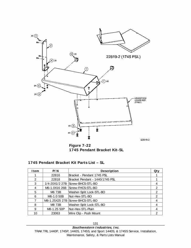
131 Southwestern Industries, Inc.
TRAK TRL 1440P, 1745P, 1440S, 1745S, and Sport 1440S, & 1745S Service, Installation, Maintenance, Safety, & Parts Lists Manual
1745 Pendant Bracket Kit Parts List – SL
Item P/N Description Qty 1 22816 Bracket - Pendant 1745 PSL 1 2 22818 Bracket Pendant - 1440/1745 PSL 1 3 1/4-20X1/2 27B Screw-BHCS-STL-BO 4 4 M6-1.0X16 26B Screw-FHCS-STL-BO 2 5 M6 73B Washer-Split Lock-STL-BO 2 6 M6-1.0 50B Nut-Hex-STL-BO 2 7 M8-1.25X25 27B Screw-BHCS-STL-BO 4 8 M8 73B Washer-Split Lock-STL-BO 4 9 M8-1.25 50P Nut-Hex-STL-Plain 4 10 23063 Wire Clip - Push Mount 2
Figure 7-22 1745 Pendant Bracket Kit-SL

132 Southwestern Industries, Inc.
TRAK TRL 1440P, 1745P, 1440S, 1745S, and Sport 1440S, & 1745S Service, Installation, Maintenance, Safety, & Parts Lists Manual
I00200
Figure 7-23 Switch Box – 1440/1745 Model L2/LX2 CNC
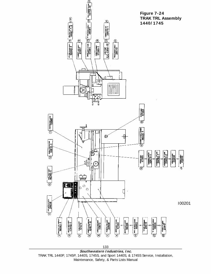
133 Southwestern Industries, Inc.
TRAK TRL 1440P, 1745P, 1440S, 1745S, and Sport 1440S, & 1745S Service, Installation, Maintenance, Safety, & Parts Lists Manual
I00201
Figure 7-24 TRAK TRL Assembly 1440/1745
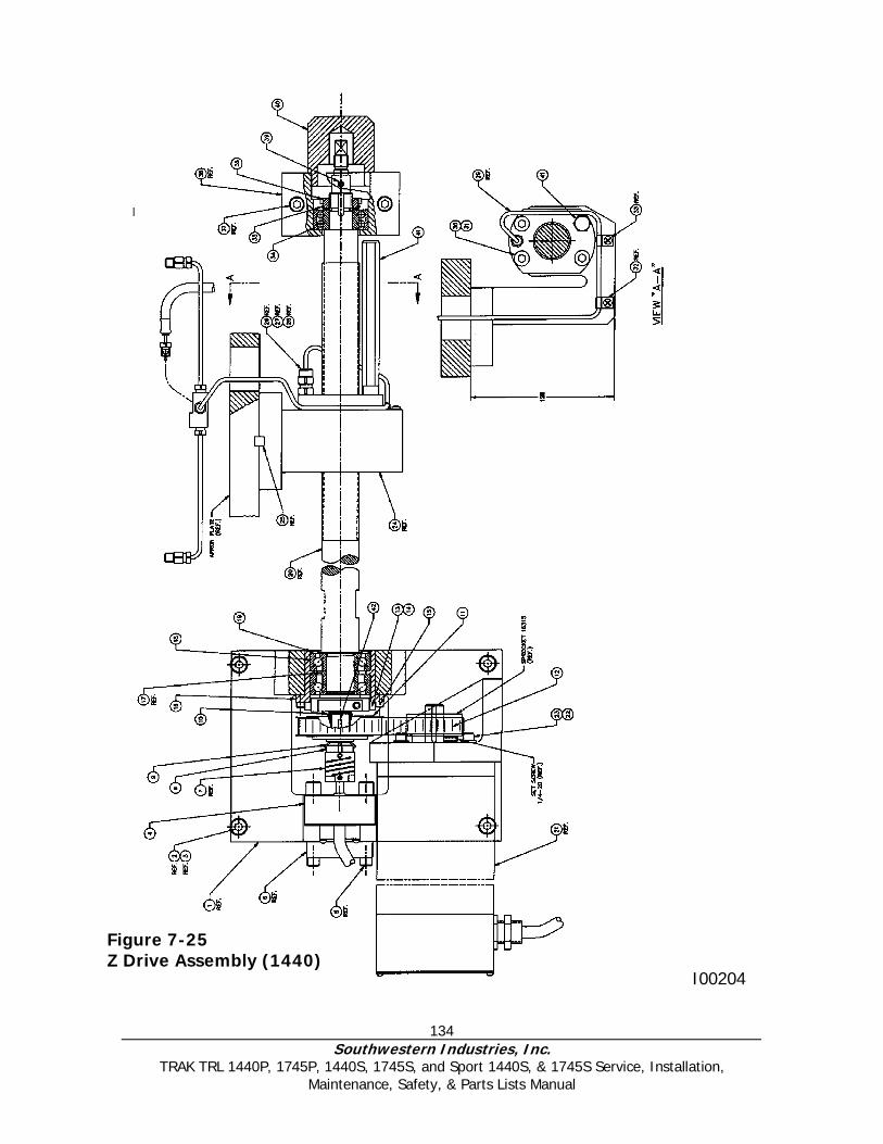
134 Southwestern Industries, Inc.
TRAK TRL 1440P, 1745P, 1440S, 1745S, and Sport 1440S, & 1745S Service, Installation, Maintenance, Safety, & Parts Lists Manual
I00204
Figure 7-25 Z Drive Assembly (1440)
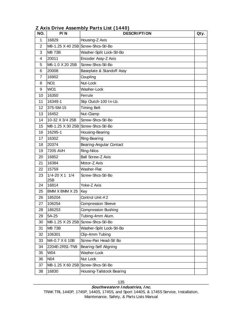
135 Southwestern Industries, Inc.
TRAK TRL 1440P, 1745P, 1440S, 1745S, and Sport 1440S, & 1745S Service, Installation, Maintenance, Safety, & Parts Lists Manual
Z Axis Drive Assembly Parts List (1440) NO. P/N DESCRIPTION Qty.
1 16829 Housing-Z Axis 2 M8-1.25 X 40 25B Screw-Shcs-Stl-Bo 3 M8 73B Washer-Split Lock-Stl-Bo 4 20011 Encoder Assy-Z Axis 5 M6-1.0 X 20 25B Screw-Shcs-Stl-Bo 6 20008 Baseplate & Standoff Assy 7 16902 Coupling 8 NO1 Nut-Lock 9 WO1 Washer-Lock 10 16350 Ferrule 11 16349-1 Slip Clutch-100 In-Lb. 12 375-5M-15 Timing Belt 13 16452 Nut-Clamp 14 10-32 X 3/4 25B Screw-Shcs-Stl-Bo 15 M8-1.25 X 30 25B Screw-Shcs-Stl-Bo 16 16295-1 Housing-Bearing 17 16302 Ring-Bearing 18 20374 Bearing-Angular Contact 19 7205 AVH Ring-Nilos 20 16852 Ball Screw-Z Axis 21 16384 Motor-Z Axis 22 15759 Washer-Flat 23 1/4-20 X 1 1/4
25B Screw-Shcs-Stl-Bo
24 16814 Yoke-Z Axis 25 8MM X 8MM X 25 Key 26 185204 Control Unit-#2 27 106254 Compression Sleeve 28 186253 Compression Bushing 29 5A-25 Tubing-4mm Alum. 30 M8-1.25 X 25 25B Screw-Shcs-Stl-Bo 31 M8 73B Washer-Split Lock-Stl-Bo 32 106301 Clip-4mm Tubing 33 M4-0.7 X 6 10B Screw-Pan Head-Stl Bo 34 2204E-2RS1-TN9 Bearing-Self Aligning 35 W04 Washer-Lock 36 N04 Nut Lock 37 M8-1.25 X 60 25B Screw-Shcs-Stl-Bo 38 16830 Housing-Tailstock Bearing

136 Southwestern Industries, Inc.
TRAK TRL 1440P, 1745P, 1440S, 1745S, and Sport 1440S, & 1745S Service, Installation, Maintenance, Safety, & Parts Lists Manual
39 M5-0.8 X 6 40B Screw-Set-Cup Point-Stl-Bo 40 16311 Cover-Tailstock Housing 41 20086-1 Stop 42 98481A090 Key-Woodruff #3 (1/8 X 1/2)
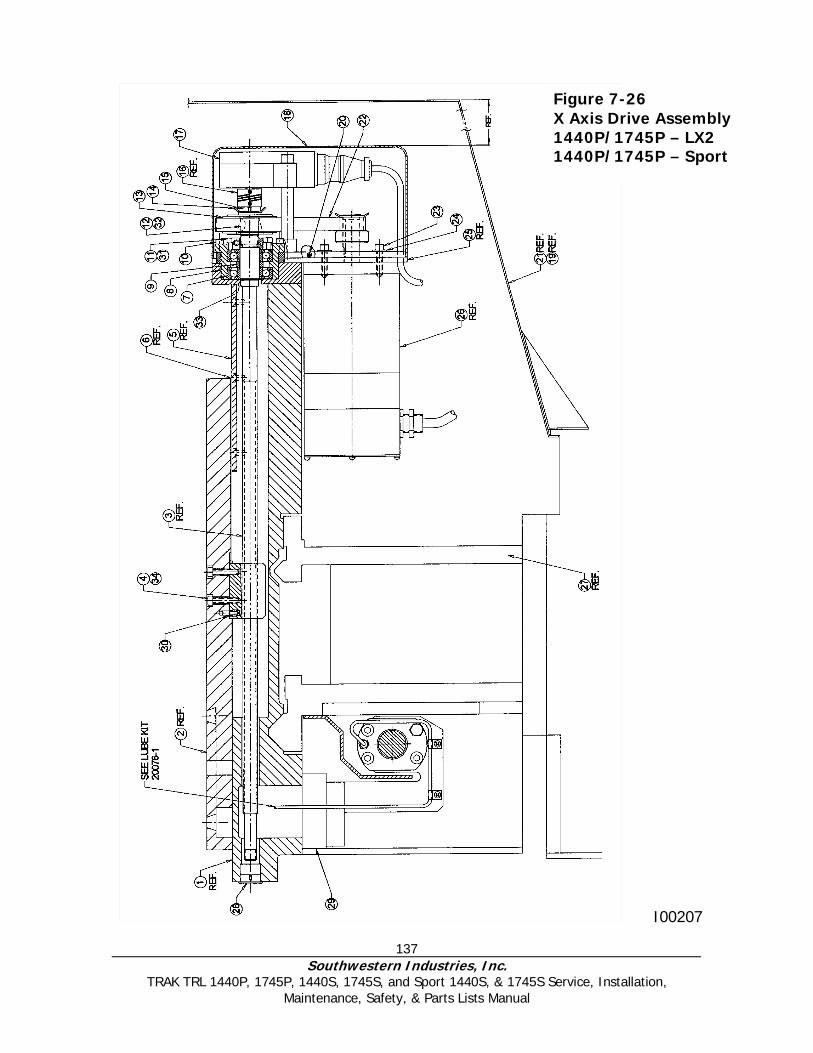
137 Southwestern Industries, Inc.
TRAK TRL 1440P, 1745P, 1440S, 1745S, and Sport 1440S, & 1745S Service, Installation, Maintenance, Safety, & Parts Lists Manual
I00207
Figure 7-26 X Axis Drive Assembly 1440P/1745P – LX2 1440P/1745P – Sport
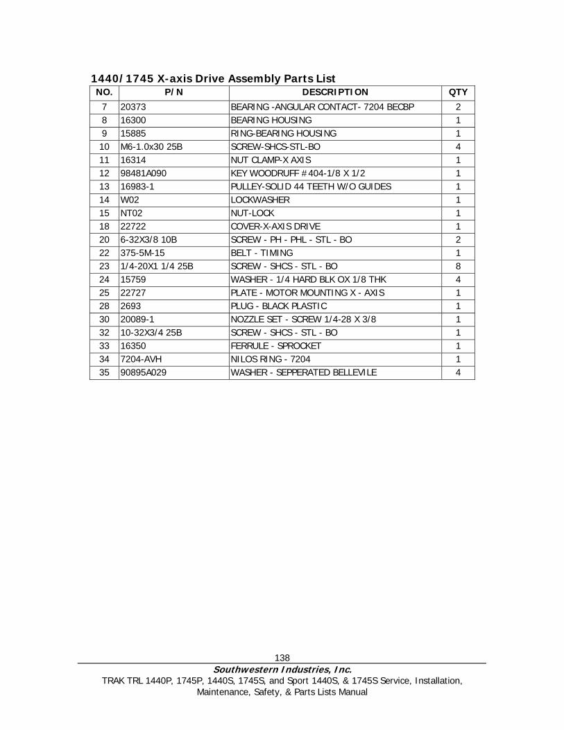
138 Southwestern Industries, Inc.
TRAK TRL 1440P, 1745P, 1440S, 1745S, and Sport 1440S, & 1745S Service, Installation, Maintenance, Safety, & Parts Lists Manual
1440/1745 X-axis Drive Assembly Parts List NO. P/N DESCRIPTION QTY
7 20373 BEARING -ANGULAR CONTACT- 7204 BECBP 2 8 16300 BEARING HOUSING 1 9 15885 RING-BEARING HOUSING 1 10 M6-1.0x30 25B SCREW-SHCS-STL-BO 4 11 16314 NUT CLAMP-X AXIS 1 12 98481A090 KEY WOODRUFF #404-1/8 X 1/2 1 13 16983-1 PULLEY-SOLID 44 TEETH W/O GUIDES 1 14 W02 LOCKWASHER 1 15 NT02 NUT-LOCK 1 18 22722 COVER-X-AXIS DRIVE 1 20 6-32X3/8 10B SCREW - PH - PHL - STL - BO 2 22 375-5M-15 BELT - TIMING 1 23 1/4-20X1 1/4 25B SCREW - SHCS - STL - BO 8 24 15759 WASHER - 1/4 HARD BLK OX 1/8 THK 4 25 22727 PLATE - MOTOR MOUNTING X - AXIS 1 28 2693 PLUG - BLACK PLASTIC 1 30 20089-1 NOZZLE SET - SCREW 1/4-28 X 3/8 1 32 10-32X3/4 25B SCREW - SHCS - STL - BO 1 33 16350 FERRULE - SPROCKET 1 34 7204-AVH NILOS RING - 7204 1 35 90895A029 WASHER - SEPPERATED BELLEVILE 4
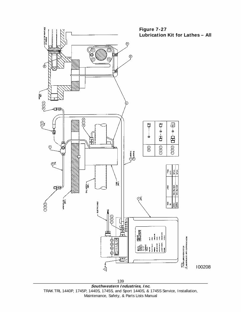
139 Southwestern Industries, Inc.
TRAK TRL 1440P, 1745P, 1440S, 1745S, and Sport 1440S, & 1745S Service, Installation, Maintenance, Safety, & Parts Lists Manual
I00208
Figure 7-27 Lubrication Kit for Lathes – All

140 Southwestern Industries, Inc.
TRAK TRL 1440P, 1745P, 1440S, 1745S, and Sport 1440S, & 1745S Service, Installation, Maintenance, Safety, & Parts Lists Manual
Lubrication Kit Parts List No. P/N Description Qty 1 CMV-15 00441-4 Oil Pump-110V 2 Litre 1 2 B-108 Hose-Flexible No Guard 108" LG 1 3 186001 Adaptor-Straight 1/8 NPT X 5/16-24 1 4 106254 Compression Sleeve-4mm 1 5 186252 Compression Bushing 1 6 5A-25 Tubing-4mm Alum X 20" Lg 2 7 185210 Control Unit CSA-5 (Bijur Only) 1 8 186251 Compression Nut-5/16-24 1 9 186423 Junction-4 Way 5/16-24 1 10 B-124 Hose-Flexible No Guard 124" Lg 1 11 106301 Clip-4mm 1 12 M4-0.7 X 6 10B Screw-Pan Head-Phillips-STL BO 1 13 20440 Orifice-TRL Saddle 1

141 Southwestern Industries, Inc.
TRAK TRL 1440P, 1745P, 1440S, 1745S, and Sport 1440S, & 1745S Service, Installation, Maintenance, Safety, & Parts Lists Manual
Figure 7-28 Brake Adjustment (1745)
Southwestern Industries, Inc
TRAK Warranty Policy
Warranty TRAK products are warranted to the original purchaser to be free from defects in work-manship and materials for the following periods:
Warranty Period Product
Materials Factory Labor New TRAK 1 Year 1 Year Any EXCHANGE Unit 90 Days 90 Days
The warranty period starts on the date of the invoice to the original purchaser from Southwestern Industries, Inc. (SWI) or their authorized distributor. If a unit under warranty fails, it will be repaired or exchanged at our option for a properly functioning unit in similar or better condition. Such repairs or exchanges will be made FOB Factory/Los Angeles or the location of our nearest factory representative or authorized distributor.
Disclaimers of Warranties • This warranty is expressly in lieu of any other warranties, express or implied, including any implied
warranty of merchantability or fitness for a particular purpose, and of any other obligations or liability on the part of SWI (or any producing entity, if different).
• Warranty repairs/exchanges do not cover incidental costs such as installation, labor, freight, etc.
• SWI is not responsible for consequential damages from use or misuse of any of its products.
• TRAK products are precision mechanical/electromechanical measurement systems and must be
given the reasonable care that these types of instruments require:
• Replacement of chip scrapers and wipers is the responsibility of the customer. Consequently, the warranty does not apply if chips have been allowed to enter the mechanism.
• Accidental damage, beyond the control of SWI, is not covered by the warranty. Thus, the warranty
does not apply if an instrument has been abused, dropped, hit, disassembled or opened.
• Improper installation by or at the direction of the customer in such a way that the product consequently fails, is considered to be beyond the control of the manufacturer and outside the scope of the warranty.