lathe coordinate system - walla walla universityralph.stirling/classes/engr480/... · •...
TRANSCRIPT
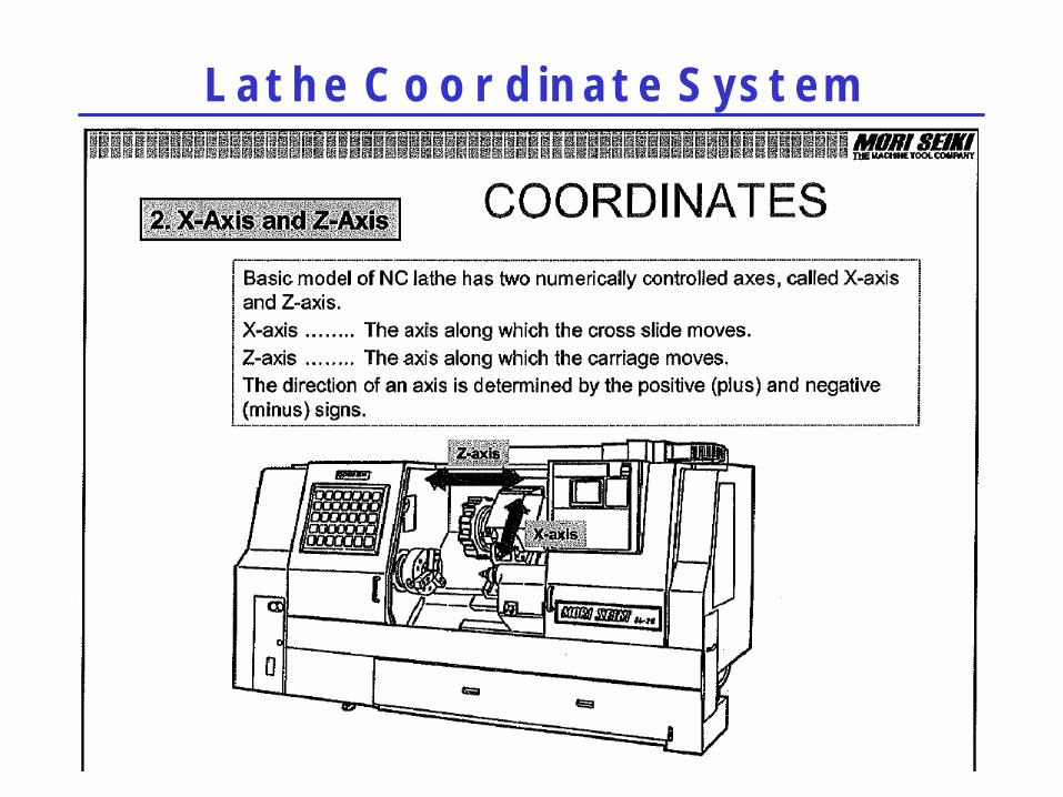
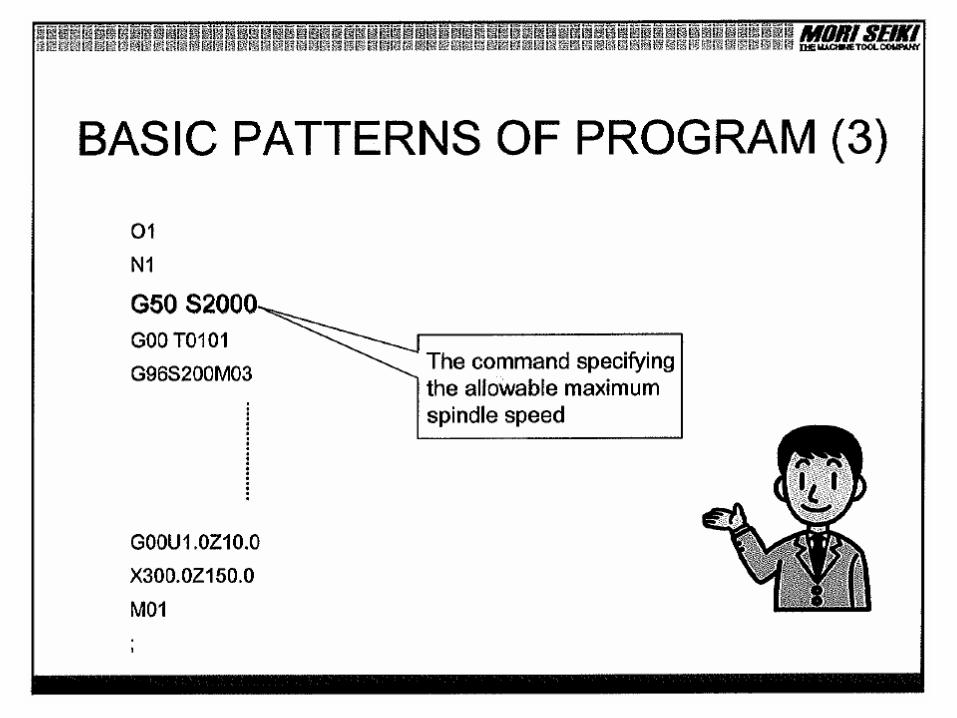
Lathe Coordinate System

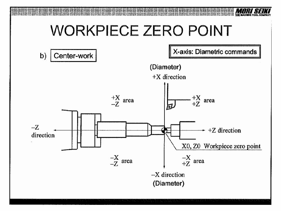
Workpiece Zero Point
• Coordinate system zero point is– centerline of spindle (X)
• with normal spindle rotation, machining is in +X– finish face of part (Z)
• Machining is in –Z if Z=0 is finish face• Second ops may use back side of part as Z=0
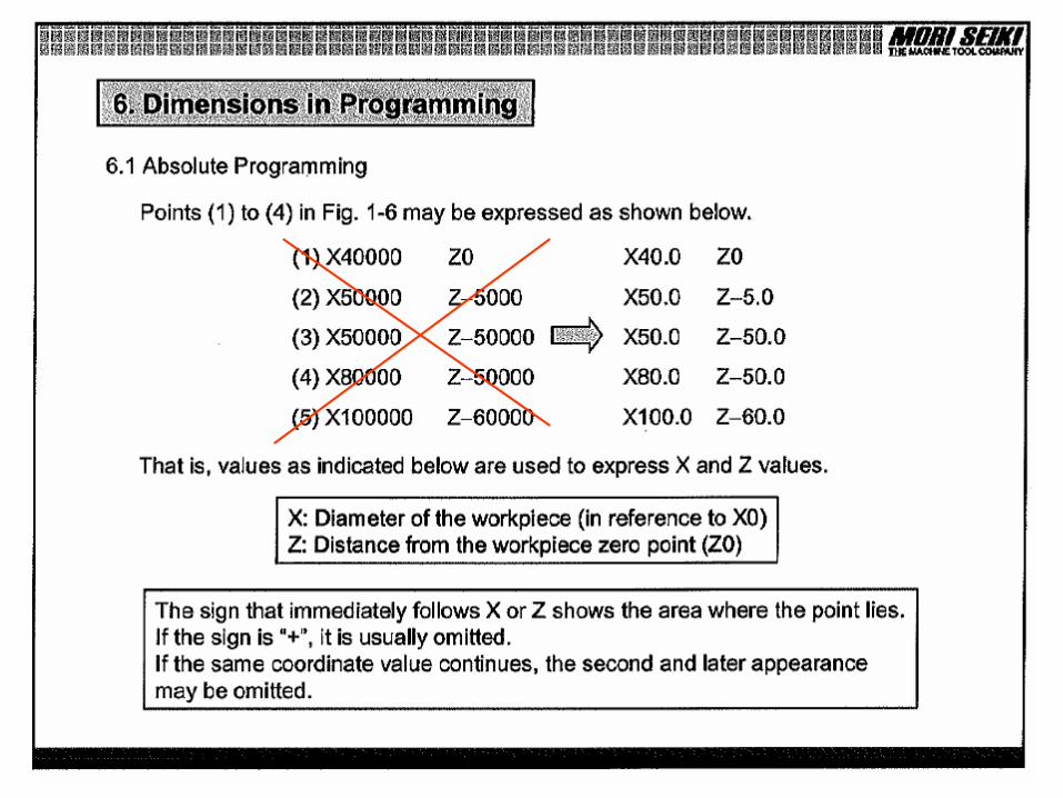
• X dimensions are diameter, not radius

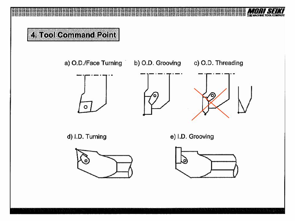


Lathe Tooling
• Turning• Boring• OD Grooving• ID Grooving• Face Grooving• OD Threading• ID Threading

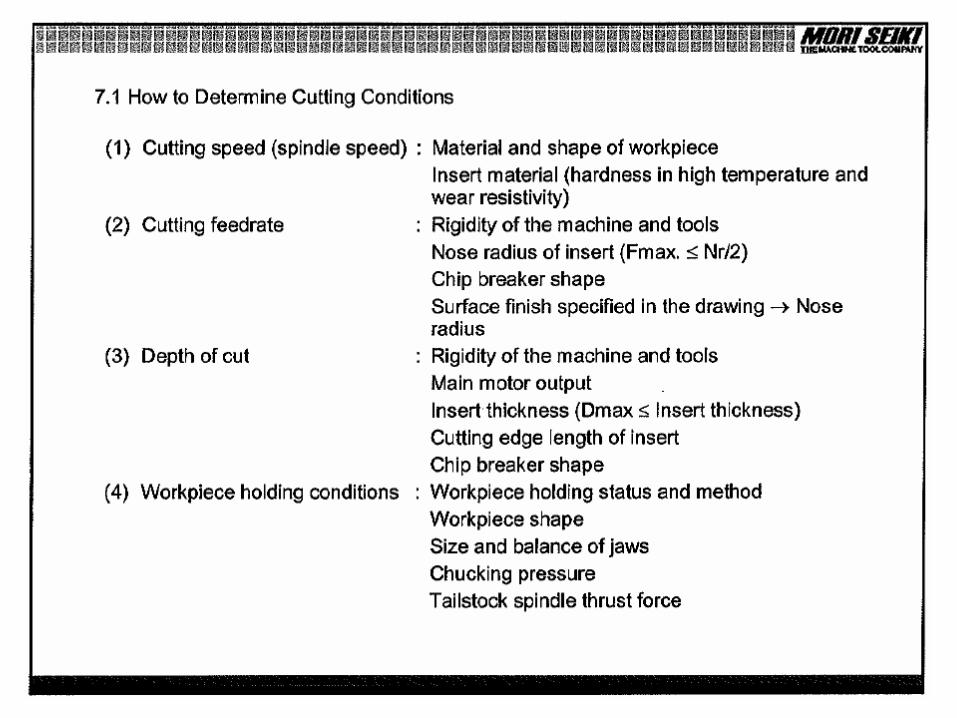
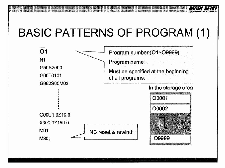
CNC Lathe Programming

G-Codes for Turning
Limit spindle speedG50Return to reference pointG28Metric systemG21Inch systemG20DwellG04CCW Circular interpolationG03CW Circular interpolationG02Linear interpolation (feeding)G01Rapid positioningG00

G-Codes for Turning
Feed per revolution modeG99Feed per minute modeG98Constant spindle speed modeG97Constant surface speed modeG96Threading cycleG76Facing cycleG72Roughing cycleG71Finishing cycleG70Select work coord system #1G54

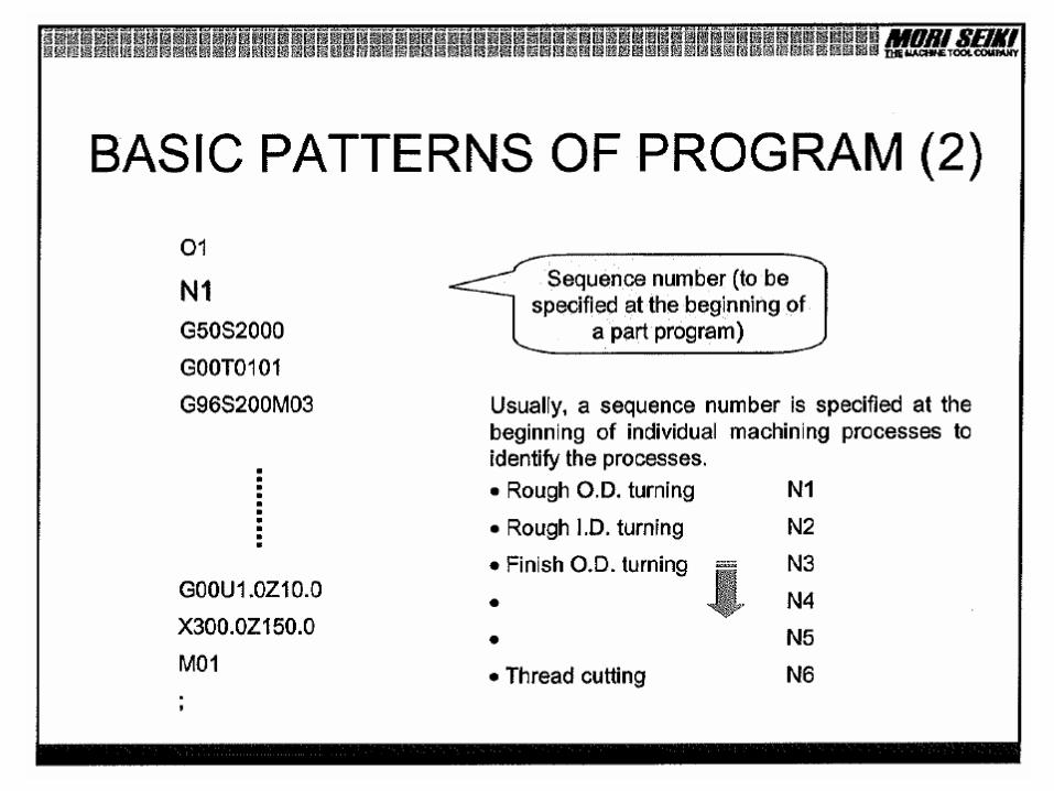
M-Codes for Turning
Program endM30Open chuckM11Close chuckM10Stop coolantM09Start coolantM08Stop spindleM05Start spindle (reverse rotation)M04Start spindle (normal rotation)M03Opt. Program Stop (panel controlled)M01Program StopM00