latent fingerprint matching - michigan state...
TRANSCRIPT

1
Latent Fingerprint Matching
Anil K. Jain, Abhishek Nagar and Karthik Nandakumar
Abstract
Latent fingerprint identification is of critical importance in forensics. While tremendous progress
has been made in the field of automatic fingerprint identification, latent fingerprint matching continues
to be a difficult problem because the challenges involved in latent print matching are quite different from
rolled (full) fingerprint matching. Poor quality of friction ridge impressions, small finger area and large
non-linear distortion are the main factors that affect latent fingerprint matchers. We propose a system
for matching latent images with full fingerprints that uses minutiae as well as ridge information as the
discriminative features. We have developed a minutiae-based fingerprint matcher that takes into account
the specific characteristics of the latent matching problem. The ridge correlation matcher determines
the degree of similarity in the ridge flow patterns of latents and full-print images. Experimental results
on the NIST Special Database-27 which consists of 258 latents and their corresponding full fingerprint
images indicate that the fusion of minutiae and ridge correlation matchers leads to good recognition
performance despite the inherently difficult nature of the problem.
Index Terms
Latent fingerprints, fingerprint matching, minutiae matcher, ridge-correlation.
This research was supported by the National Institute of Justice.
December 20, 2007 DRAFT
MSU Technical Report, MSU-CSE-07-203, December 2007

2
I. INTRODUCTION
Fingerprint images can be broadly classified into three categories, namely, (i) rolled/full, (ii)
plain/flat and (iii) latent [1]–[3] (see Figure 1). Rolled fingerprint images are obtained by rolling
a finger from one side to the other (“nail-to-nail”) in order to capture all the ridge-details of
a finger. Plain impressions are those in which the finger is pressed down on a flat surface but
not rolled. While plain impressions cover a smaller area than rolled prints, they typically do not
have the distortion introduced during rolling. Rolled and plain impressions are obtained either
by scanning the inked impression on paper or by using live-scan devices. Since rolled and plain
fingerprints are acquired from co-operative subjects, they are typically of high quality and rich
in information content. In contrast, latent fingerprints are lifted from surfaces of objects that are
inadvertently touched or handled by a person through a variety of means ranging from simply
photographing the print to more complex dusting or chemical processes [4], [5]. It is the latent
fingerprints that are of utmost importance in forensics to apprehend a criminal or to verify the
identity of a suspect.
(a) (b) (c)
Fig. 1. Three types of fingerprint images. (a) Rolled/full print, (b) Plain/flat print and (c) Latent print.
Latent fingerprints obtained from crime scenes have served as crucial evidence in forensic
identification for more than a century. However, there have been instances where mistakes in
latent fingerprint identification have led to wrongful convictions. One of the most high profile
cases in which such a mistake was made is the case of Brandon Mayfield who was wrongly
December 20, 2007 DRAFT
MSU Technical Report, MSU-CSE-07-203, December 2007
3
apprehended in the Madrid train bombing incident after a latent fingerprint obtained from the
bombing site was incorrectly matched with his fingerprint [6]. An extensive account of similar
cases have been brought to light by Innocence project [7]. Due to these incidents and findings,
the importance of latent fingerprints as forensic evidence has been undermined. This is evident
from a recent ruling of a Baltimore court [8] which excluded fingerprints as evidence in a murder
trial because the prosecutor was not able to justify the procedure followed for latent fingerprint
matching as being sufficiently error free.
It is often argued that matching a latent fingerprint to a full-print is more of an “art” than
“science” [9] because the matching is based on subjective appraisal of the two fingerprints in
question by a human examiner. Moreover, the decisions made by latent examiners are required to
be “crisp”, i.e., an examiner can provide only one of the three decisions, viz., individualization
(identification or match), exclusion (non-match) and inconclusive [4], [5]. Often latent examiners
have a huge backlog of cases and are usually under time pressure to evaluate a fingerprint pair,
particularly in high profile cases. Therefore, it is very important that the cases sent to latent
examiners be efficiently selected and prioritized so that he/she can spend adequate amount of
time in matching them. One way to achieve this goal is to design an efficient and highly accurate
automatic latent to full-print matching system which should be able to provide a quantitative
estimate of the probability that two fingerprints being compared belong to same finger.
In order to deal with efficiency, the concept of “Lights-Out System” for fingerprint matching
has been introduced [2]. A “Lights-Out System” for fingerprint identification is characterized
by no human intervention throughout the whole identification process. Such a system should
automatically extract features from fingerprints and match them with a gallery database to obtain
a set of possible “hits” with high confidence so that no human intervention is required. However,
in latent matching only “Semi Lights-Out Systems” are feasible due to the limitations of existing
technology. In a “Semi-Lights-Out System” some human intervention is allowed during feature
extraction e.g. orienting the fingerprint, marking the region of interest, etc. A “Semi Lights-Out
System” outputs a list of candidates that need to be examined by a latent examiner to accept or
reject a fingerprint pair as a match.
Although tremendous progress has been made in developing automated fingerprint identifica-
tion systems (AFIS), most of these systems work well only in scenarios where the matching is
performed between rolled or plain fingerprint images. The results of Fingerprint Vendor Tech-
December 20, 2007 DRAFT
MSU Technical Report, MSU-CSE-07-203, December 2007

4
TABLE I
PERFORMANCE OF A REPRESENTATIVE LATENT MATCHER (LATENT VS. ROLLED OR LATENT VS. PLAIN) ON A DATABASE OF
MORE THAN 40 MILLION SUBJECTS [2]
Quality of Latents Type of Mate
Latent vs. Rolled Latent vs. Plain Latent vs. Mixed Rolled/Plain
Good and Better 94% 63% 78%
Average Case Work 54% 39% 47%
nology Evaluation (FpVTE) conducted by NIST [10] show that the most accurate commercial
fingerprint matchers can achieve a rank-one identification rate of more than 99.4% on a database
of 10, 000 plain fingerprint images (see results of Medium Scale Test on page 56 in [10]). On the
other hand, the accuracy of latent to full print match continues to be quite low. The NIST latent
fingerprint testing workshop reports that the rank-one accuracy of an automatic latent matcher
can be as low as 54% on a large database of more than 40 million subjects [2] (see Table I).
AFIS systems have not been very effective so far in matching latent fingerprints because
the challenges involved in latent print matching are quite different from full (rolled or plain)
fingerprint matching. The difficulty in latent matching is due to three main reasons: (i) poor
quality of latent prints in terms of the clarity of ridge information, (ii) latent print area can
be quite small compared to the full print and (iii) large non-linear distortion due to pressure
variations. Figure 2 shows a sample latent image from the NIST Special Database-27 along
with its corresponding full print image. In Figure 2(a), the ridge information in the middle of
the image is obscured by the presence of background noise, extraneous markings and other
spurious friction ridges surrounding it. Further, while a typical rolled fingerprint has more than
60 minutiae, a typical latent fingerprint may have only 15 usable minutiae [2]. Thus, latent
fingerprint identification is a difficult problem which needs immediate attention.
The latent identification process can be divided into four steps, namely, (i) Analysis, (ii)
Comparison, (iii) Evaluation and (iv) Verification. This process is commonly referred to as the
ACE-V procedure in latent fingerprint literature [11].
• Analysis refers to assessing the latent fingerprint to determine whether sufficient ridge
information is present in the image to be processed and to mark the features along with the
December 20, 2007 DRAFT
MSU Technical Report, MSU-CSE-07-203, December 2007

5
(a) (b)
Fig. 2. A sample fingerprint pair from the NIST Special Database-27. (a) Latent print, (b) full print.
associated quality information. The latent print analysis is usually performed manually by a
human expert in total objectivity (without having access to a reference print). Features in a
fingerprint can be divided into three levels. Level 1 features usually refer to features based
on global pattern of the fingerprint. Level 2 features refer mainly to minutiae points and
Level 3 features refer to the other characteristic features like ridge shape, pores, incipient
ridges, creases, worts, etc. Note that level 1 features are not very informative for matching
and are typically used for fingerprint classification which can facilitate exclusion of full
prints whose patterns do not match with the query latent print. Level 2 features however
are considered the most informative features in a fingerprint.
• Comparison refers to the stage where an examiner compares a latent image to a reference
print to ascertain their similarities or dissimilarities. Features at all three levels are compared
at this stage.
• Evaluation stage refers to classifying the fingerprint pairs as individualization (identification
or match), exclusion (non-match) or inconclusive.
• Verification is the process of re-examination of a fingerprint pair independently by another
examiner in order to verify the results of the first examiner.
December 20, 2007 DRAFT
MSU Technical Report, MSU-CSE-07-203, December 2007

6
(a) (b)
Fig. 3. A sample fingerprint pair from the NIST Special Database-27 with minutiae, incipient ridges, dots and pores marked.
(a) Latent print with manually marked features, (b) full print with automatically extracted minutiae. Pores are shown as small
dots, incipients are shown as thick cyan lines, dots are shown as yellow squares and minutiae are marked with stars with tail
oriented along minutia direction.
In this study, we assume that the analysis of the latent print has been performed manually
by a latent examiner who has marked the minutiae details, the ridge flow information and other
level 3 features such as incipient ridges. We focus mainly on the comparison stage where the
manually marked features in the latent are matched against the features extracted automatically
from the full-print images (see figure 3). Our contributions are three-fold: (i) we present a
minutiae-based matcher that takes into account the specific characteristics of matching a latent
with its corresponding full-print; (ii) we develop a ridge-correlation based matcher to ascertain
the similarity in the ridge structure between the latent and full-print images; (iii) we perform a
fusion of the minutiae and ridge-correlation matchers to improve the overall matching accuracy.
II. MINUTIAE-BASED MATCHING
Minutiae-based matching is an important part of the overall matching procedure proposed in
this study. Matching latent fingerprints with full-prints is quite different in certain aspects and in
fact more difficult than matching a rolled or flat print with a print obtained in a similar manner.
We therefore make the following assumptions that are reasonable while matching a latent with
December 20, 2007 DRAFT
MSU Technical Report, MSU-CSE-07-203, December 2007

7
Fig. 4. Cumulative Match Characteristic (CMC) curve corresponding to matching manually marked latent minutiae with
manually marked full-print minutiae using Neutechnologija Verifinger 4.2.
a full-print.
1) The latent print is fully contained in its corresponding full-print.
2) Given that the minutiae in latent are marked by a latent examiner, there is little chance of
a spurious minutia being present in the latent.
3) Full-print is typically of good quality and hence the chances of missing a minutiae in the
full-print is negligible.
Based on the above assumptions, when latent print is matched against its corresponding full-
print, all the latent minutiae are expected to have a match in the full-print while the converse
need not be true.
Commercial minutiae-based matchers are typically designed for full-print to full-print matching
and do not take into account the specific characteristics of latent to full-print matching. Hence,
they fail to perform well for the task of latent minutiae matching. For example, the COTS matcher
in [12] has a rank-one accuracy of 95% on the Medium Scale Test in FpVTE [10]. However, the
same matcher has a rank-one accuracy of about 70% when matching latent minutiae to full-print
minutiae in the NIST-SD27 database (see Figure 4).
December 20, 2007 DRAFT
MSU Technical Report, MSU-CSE-07-203, December 2007
8
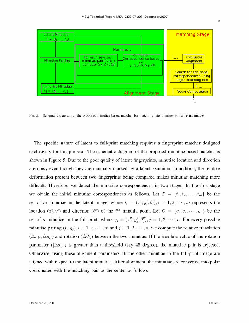
Fig. 5. Schematic diagram of the proposed minutiae-based matcher for matching latent images to full-print images.
The specific nature of latent to full-print matching requires a fingerprint matcher designed
exclusively for this purpose. The schematic diagram of the proposed minutiae-based matcher is
shown in Figure 5. Due to the poor quality of latent fingerprints, minutiae location and direction
are noisy even though they are manually marked by a latent examiner. In addition, the relative
deformation present between two fingerprints being compared makes minutiae matching more
difficult. Therefore, we detect the minutiae correspondences in two stages. In the first stage
we obtain the initial minutiae correspondences as follows. Let T = {t1, t2, · · · , tm} be the
set of m minutiae in the latent image, where ti = (xti, y
ti , θ
ti), i = 1, 2, · · · ,m represents the
location (xti, y
ti) and direction (θt
i) of the ith minutia point. Let Q = {q1, q2, · · · , qn} be the
set of n minutiae in the full-print, where qj = (xqj , y
qj , θ
qj ), j = 1, 2, · · · , n. For every possible
minutiae pairing (ti, qj), i = 1, 2, · · · ,m and j = 1, 2, · · · , n, we compute the relative translation
(∆xij, ∆yij) and rotation (∆θij) between the two minutiae. If the absolute value of the rotation
parameter (|∆θij|) is greater than a threshold (say 45 degree), the minutiae pair is rejected.
Otherwise, using these alignment parameters all the other minutiae in the full-print image are
aligned with respect to the latent minutiae. After alignment, the minutiae are converted into polar
coordinates with the matching pair as the center as follows
December 20, 2007 DRAFT
MSU Technical Report, MSU-CSE-07-203, December 2007

9
rqj
eqj
γqj
=
√(xq
j − xt∗)2 + (yqj − yt∗)2
tan−1(yq
j−yt∗xq
j−xt∗)
θqj − θt
∗
,
(1)
where (xqj , y
qj , θ
qj ), j = 1, 2, · · · , n are the coordinates of the full-print minutia after alignment,
(xt∗, y
t∗, θ
t∗) are the coordinates for the reference (matching) latent minutia and (rq
j , eqj , γ
qj ) are
the coordinates of the full-print minutiae in the polar coordinate system. Note that r represents
the radial distance, e represents the angle that the line joining the minutia and the center makes
with x-axis and γ represents the relative direction of the minutia with respect to the reference
minutia. Similarly, the latent minutiae are also expressed in the polar coordinate system as
{(rti , e
ti, γ
ti), i = 1, 2, · · · ,m}. While the representation of minutiae in the the polar coordinate
system is similar to the representation used in [13], our matching procedure is different from
the one described in [13].
For each latent minutia (say (rti , e
ti, γ
ti )), we obtain a list of prospective full-print minutiae
matches by finding the full-print minutiae (say (rqj , e
qj , γ
qj )) lying in its neighborhood such that
Ψ(eqj , e
ti) < εj
e, (2)
where Ψ(θ1, θ2) = min(|θ1−θ2|, 360−|θ1−θ2|) is the angular difference function, εje = tan−1( εe
rqj)
and εe is a constant threshold. The prospective matches are sorted according to radial angle e
and list is searched for the first minutia (rqj , e
qj , γ
qj ) that satisfies the following conditions:
|rqj − rt
i | < εr, (3)
Ψ(γqj , γ
ti) < εγ, (4)
where εr, and εγ are constant thresholds. The minutia that satisfied Eqns 2, 3 and 4 is assigned
as the corresponding minutia for the latent minutia (rti , e
ti, γ
ti). We thus obtain the set of corre-
spondences for the latent minutiae based on the alignment generated by every minutiae pair. We
retain only the set of correspondences that produces the maximum number of matching minutiae
(say L).
Due to the large relative deformation between the latent and full-print images, the matching
scheme described earlier may not identify all the true minutiae correspondences between the
December 20, 2007 DRAFT
MSU Technical Report, MSU-CSE-07-203, December 2007

10
latent and the full-print. We overcome the problem due to deformation in the following manner.
Based on all the matching minutia pairs identified in the previous step, we compute a new set
of alignment parameters using the Procrustes algorithm [14]. The new alignment parameters are
more robust because they are computed using all the matching minutiae. The full-print minutiae
are aligned with the latent minutiae and the known correspondences in the two minutiae sets are
removed. For each latent minutia (say (xt, yt, θt)) for which a corresponding full-print minutia
has not been identified, we verify whether there exists a full-print minutia (say (xq, yq, θq)) such
that
√(xq − xt)2 + (yq − yt)2 + wθ ∗ (Ψ(θq, θt)) < εs, (5)
where wθ is the weight assigned to the angular difference and εs is a constant threshold. If
such a full-print minutiae can be found, we consider it as an additional correspondence. Let the
number of additional correspondences obtained using this larger bounding box be Lnew. Since
these additional correspondences are less reliable than the initial correspondences, we assign
a smaller weight to the additional correspondences and compute the weighted correspondence
score L′ as
L′= L + w1 ∗ Lnew, (6)
where w1 < 1.
A number of match score functions have been proposed to compute the similarity between two
fingerprints. For example, Jain et al. [13] proposed the function in equation (7) that normalizes
the number of matched minutiae pairs based on the number of minutiae in the template and query
prints. If L is the number of matching minutiae pairs and m and n are the number of minutiae
in the query and template prints, respectively, then the match score Sm can be computed as,
Sm = 100L
max(m,n). (7)
The score function in equation (7) does not account for the fact that there may be only a partial
overlap between the two prints being matched in which case the score will be undesirably low
even if the overlapping area is perfectly matching. A modified score function was proposed in
Jain et al. [15] to account for these limitations. If mo and no are the number of minutiae in
December 20, 2007 DRAFT
MSU Technical Report, MSU-CSE-07-203, December 2007

11
the overlapping regions of the query and template prints, respectively after alignment, then the
match score Sm is computed as
Sm = L× L− w2 ∗ (mo − L)
mo + 1× L− w2 ∗ (no − L)
no + 1, (8)
where w2 is the weight used to penalize non-matching minutiae (set to 0.2 in [15]). The score
function in equation (8) is also not well-suited for matching latents with full-prints due to two
reasons. Since the number of matching minutiae can be quite small (an average of 15 in NIST SD-
27) in latent to full-print matching, the first product term (L) in equation (8) makes the score
highly dependent on just the number of matches. Secondly, due to the poor quality of latent
images, there may be many missing minutiae in the latent. Therefore, while latent minutiae that
do not have a corresponding match in the full-print must be penalized, the full-print minutiae
that do not have a match in the latent should not be penalized. Based on these considerations,
we propose a new match score function which is computed as follows.
Sm =L′
m + 1+
L′
no + 1− w ∗ m− L
′
m + 1, (9)
where w is the weight given to the penalty term and no is the number of full-print minutiae
lying the overlapping segmented region after the full-print has been aligned with the latent print
during the minutia matching procedure.
We can summarize the complete minutiae-based matching algorithm as follows.
1) Consider each latent - full-print minutia pair (ti, qj), compute the transformation parameters
(∆xij, ∆yij, ∆θij).
2) Transform all the full-print minutiae according to (∆xij, ∆yij, ∆θij).
3) If ∆θij > εθ do not consider (ti, qj) as a possible correspondence for further consideration
and start from step 1 with a different minutia pair (ti, qj).
4) Compute the correspondences between latent and full-print minutiae using equations (3)
(2) and (4).
5) Follow steps (1) to (4) until all possible pairs (ti, qj) have been considered.
6) Find the pair (ti, qj) which gives the largest number of correspondences (say L). These L
correspondences are retained for further processing.
7) Align the corresponding minutiae obtained in step (6) using Procrustes analysis.
December 20, 2007 DRAFT
MSU Technical Report, MSU-CSE-07-203, December 2007
12
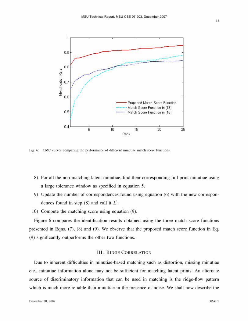
Fig. 6. CMC curves comparing the performance of different minutiae match score functions.
8) For all the non-matching latent minutiae, find their corresponding full-print minutiae using
a large tolerance window as specified in equation 5.
9) Update the number of correspondences found using equation (6) with the new correspon-
dences found in step (8) and call it L′ .
10) Compute the matching score using equation (9).
Figure 6 compares the identification results obtained using the three match score functions
presented in Eqns. (7), (8) and (9). We observe that the proposed match score function in Eq.
(9) significantly outperforms the other two functions.
III. RIDGE CORRELATION
Due to inherent difficulties in minutiae-based matching such as distortion, missing minutiae
etc., minutiae information alone may not be sufficient for matching latent prints. An alternate
source of discriminatory information that can be used in matching is the ridge-flow pattern
which is much more reliable than minutiae in the presence of noise. We shall now describe the
December 20, 2007 DRAFT
MSU Technical Report, MSU-CSE-07-203, December 2007

13
Fig. 7. Orientation vector computation at different points on a ridge.
procedure for obtaining the correlation score between the sets of ridges in latent and full-print
images being matched. Let a ridge be represented as Rk = {Rk(i) = (xki , y
ki ), i = 1, 2, · · · , NRk}
where (xki , y
ki ) represents the location of the ith point on the kth ridge and NRk is the total number
of points in that ridge. At any point on a ridge, the orientation vector is defined as
~o =(Rk(i + δ)−Rk(i− δ))
|(Rk(i + δ)−Rk(i− δ))| , (10)
where δ is set to 10 in the experiments. For computational efficiency, we sample the ridge lines at
an interval of about 10 pixels and compute the orientation vectors at these points for both latent
and full-print ridges. Figure 7 shows the orientation vectors computed along a ridge. Thinned
ridge lines for the full-prints are obtained automatically using the algorithm described in [13]
whereas the ridges for the latent images were manually marked (see Figure 8).
The ridge correlation score between latent and full-print is computed as follows. First the ridge
lines are aligned using the parameters obtained from Procrustes analysis based on the minutiae
correspondences as described in Section II. For each ridge point in the latent image, the nearest
ridge point in the full-print image is found with the constraint that the distance between these
points is no more than a specified threshold. Then, the magnitude of difference (say di) of the
orientation vectors at these corresponding points (say qi and ti) is computed using the following
equation:
December 20, 2007 DRAFT
MSU Technical Report, MSU-CSE-07-203, December 2007

14
Fig. 8. A sample latent image with manually marked ridges from the NIST SD-27.
di = min(|~oti − ~oqi|, |~oti + ~oqi|), (11)
where ~oti and ~oqi are the orientation vectors at the corresponding ridge points in the latent and
full-print images, respectively. The ridge correlation score between two fingerprints is defined as
the average correlation score between all the ridges in the overlapping region of the two prints,
Sr = − 1
NR
NR∑i=1
di. (12)
where NR is the total number of ridge points in either print that has a corresponding ridge
point in the other image. Note that di’s represent difference in the two corresponding orientation
vectors while Sr gives the similarity between two ridges due to the negative sign in Eq. 12.
Figure 10 shows an example of the manually extracted ridges in a latent fingerprint overlaid
over the automatically extracted ridges of the corresponding full-print image. The discriminatory
power of the ridge correlation matcher can be seen from the CMC curve shown in Figure 9.
December 20, 2007 DRAFT
MSU Technical Report, MSU-CSE-07-203, December 2007

15
Fig. 9. CMC curve corresponding to the Ridge Correlation matcher.
While ridges are not as valuable as minutiae in terms of latent to full-print matching, the next
section shows that fusion of the two match scores improves the overall accuracy.
IV. FUSION OF MINUTIAE AND RIDGE CORRELATION SCORES
In order to take advantage of both the minutiae matcher and the ridge correlation matcher, it is
necessary to combine the scores to compute a new score which best discriminates the correct and
incorrect latent full-print matches. We use the min-max normalization technique and weighted
sum of scores fusion technique to perform fusion of minutiae and ridge-correlation matchers.
This particular scheme for fusion is chosen since it is more resilient to noise in either of the
two scores [16]. The min-max normalization is applied separately for each latent matching as
follows.
SNormminij=
Sminij−min(Smini
)
max(Smini)−min(Smini
), (13)
December 20, 2007 DRAFT
MSU Technical Report, MSU-CSE-07-203, December 2007

16
Fig. 10. Manually extracted ridges of latent fingerprint overlaid on the automatically extracted ridges in the corresponding
full-print image.
where Sminijcorresponds to minutiae score obtained by matching ith latent with jth full-print
image and Sminicorresponds to the set of scores obtained by matching ith latent with all the
full-print images. The ridge correlation scores are also normalized using the same procedure.
The fusion score is obtained as
SFusionij = αmin ∗ SNormminij+ αrid ∗ SNormridij
, (14)
where SNormridijis the normalized ridge correlation score and αmin (say 0.4) and αrid (say
0.6) are weights given to minutiae and ridges matching scores.
Figure 11 shows an example of a genuine pair where the fusion of ridge correlation score with
December 20, 2007 DRAFT
MSU Technical Report, MSU-CSE-07-203, December 2007

17
(a) (b)
Fig. 11. Manually extracted ridges of latent fingerprint overlaid on automatically extracted ridges of the corresponding full-print
image for case where (a) fusion score improves the rank and (b) where fusion score degrades the rank of a genuine pair.
the minutiae matching score improves the rank of the retrieved genuine full-print and another
example where it degrades the rank. It is clear that the decrease in rank in the second case is
due to the incorrect alignment obtained from the minutiae matcher.
V. EXPERIMENTS AND RESULTS
The experiments were conducted on NIST Special Database-27 [2] which contains 258 latent
fingerprints and their corresponding full-print images. These 258 latent prints are divided into
three classes namely: Good, Bad and Ugly based on the quality of latent fingerprints (see Figure
12) in the database. There are 88 “Good”, 85 “Bad” and 85 “Ugly” latent images in the database.
Since two latent images in the database had the same corresponding full-print, each latent is
compared with only 257 full-print images in all the experiments.
Since latent prints are usually lifted from a complex background, it is very difficult to design
an automatic segmentation algorithm to extract the region of interest. We therefore manually
segment the latent images while taking care that the region of interest contains the least amount
of background region. Further, since the latent fingerprints are not of good quality, ridges are
manually marked on the latent images. A sample of latent fingerprint with manually marked
ridges is shown in Figure 8.
December 20, 2007 DRAFT
MSU Technical Report, MSU-CSE-07-203, December 2007

18
(a) (b) (c)
Fig. 12. Examples of latent images in the NIST Special Database-27 from (a) “Good” category, (b) “Bad” category, and (c)
“Ugly” category.
For the latent fingerprints in NIST SD-27 database, we used the ground truth minutiae supplied
with the database for our experiments as any automatic minutiae extraction algorithm is likely to
fail due to poor quality. For full fingerprint images we experimented with both the automatically
extracted minutiae as well as the ground truth minutiae supplied with the database. Since there
are some irrelevant markings present in the full-print images, manual segmentation was done
on the full-print images to obtain a mask for the region of interest. Only the minutiae falling
inside the region of interest were considered for processing. Figure 13 shows an example of the
masks obtained for a latent as well as a full-print image. Figure 14 shows examples of latent and
full-print images with minutiae marked. It was observed that even in full-print images, automatic
minutiae extraction algorithm does not perform well in some cases.
Figure 15 shows the CMC curves corresponding to the ridge correlation score, minutiae
matching score as well as the fusion of these two scores for both ground truth full-print
minutiae as well as automatically extracted full-print minutiae. It can be seen that the fusion of
ridge correlation scores and the minutiae matching scores improves the performance to around
92% retrieval at rank 25 where the performance of the minutiae based matcher is around
88% and that for ridge correlation is around 86% for the case where full-print minutiae are
automatically extracted. In the case where ground truth minutiae were used for full-print images,
the performance of the fused system improves to around 98% retrieval at rank 25, from 95% for
minutiae based matcher and 88% for ridge correlation matcher. Note that since the alignment of
December 20, 2007 DRAFT
MSU Technical Report, MSU-CSE-07-203, December 2007

19
(a) (b)
(c) (d)
Fig. 13. Sample latent and full-print images with masks obtained by manual segmentation.
ridges were done using the parameters obtained from the minutiae matcher, there is difference
between the ridge correlation scores corresponding to automatically extracted and ground truth
full-print minutiae. We observe that even with correct manual segmentation, the performance
drops by around 5% at rank 25 when automatically extracted minutiae are used. This indicates
there is a large scope of improvement in the current minutiae extraction algorithms. Figure 16
shows the results individually for good, bad and ugly quality latent prints.
VI. SUMMARY AND FUTURE WORK
We have developed a system for matching latent fingerprints with full-prints. Due to the specific
characteristics of the latent to full-print matching problem, commercial-off-the-shelf matchers
that are generally designed for full print to full print matching do not perform well in the latent
matching scenario. We propose a minutiae matching algorithm that is specifically designed for
matching latent with full-print images. Further, we have shown that ridge correlation scores can
be combined with minutiae matching scores to improve the accuracy of the system. Experiments
December 20, 2007 DRAFT
MSU Technical Report, MSU-CSE-07-203, December 2007

20
(a) (b)
(c)
Fig. 14. Sample images from NIST SD-27 with minutiae overlaid. (a) a rolled image with ground truth minutiae overlaid, (b)
the same image as in (a) with minutiae extracted using Neurotechnologija VeriFinger 4.2 [12] and (c) shows the corresponding
latent image with minutiae overlaid.
December 20, 2007 DRAFT
MSU Technical Report, MSU-CSE-07-203, December 2007

21
(a) (b)
Fig. 15. CMC curves corresponding to the ridge correlation score, minutiae matching score and the fusion score for case (a) when
ground truth full-print minutiae are used, (b) when the minutiae in full-print are automatically extracted using Neurotechnologija
VeriFinger 4.2.
Fig. 16. CMC curves corresponding to fusion scores of Good, Bad and Ugly quality latent images in NIST SD-27 database.
Each category contains 88, 85 and 85 latent images respectively.
December 20, 2007 DRAFT
MSU Technical Report, MSU-CSE-07-203, December 2007

22
conducted on the NIST Special Database-27 which contains 258 latent and their corresponding
full-print images, shows that the proposed matcher achieves better performance compared to a
commercial-off-the-shelf matcher which is known to perform quite well on full print images.
As future work, level-3 features, e.g. incipient ridges, dots and pores, will be incorporated
during latent matching to improve the performance. It is expected that in case of a genuine
latent full-print pair, the level-3 features will also overlap when the two images are aligned
using minutiae thereby providing additional evidence for match. Note that encoding the level-3
features as additional minutiae points augmenting the available minutiae set will not be of much
help. This is because there are very few level-3 features visible in latent images while in full-
print images their number is very high leading to greater chances of random correspondence in
non-mate pairs. Another important aspect of latent fingerprint matching is enhancement of latent
fingerprints which would help avail the discriminative information available in texture of latent
images. Due to bad quality of latent images, it would be fruitful to incorporate the manually
marked ridges in the enhancement routine to obtain a reliably enhanced print.
REFERENCES
[1] D. Maltoni, D. Maio, A. K. Jain, and S. Prabhakar, Handbook of Fingerprint Recognition. Springer-Verlag, 2003.
[2] V. N. Dvornychenko and M. D. Garris, “Summary of NIST latent fingerprint testing workshop,” NISTIR 7377, November
2006, http://fingerprint.nist.gov/latent/ir 7377.pdf.
[3] P. Komarinski, Ed., Automated Fingerprint Identification Systems (AFIS). Elsevier Academic Press, 2001.
[4] H. C. Lee and R. E. Gaensslen, Eds., Advances in Fingerprint Technology. New York: CRC Press, 2001.
[5] P. M. Christophe Champod, Chris Lennard and M. Stoilovic, Eds., Fingerprints and Other ridge Skin Impressions. CRC
Press, 2004.
[6] “A review of the FBI’s Handling of the Brandon Mayfield Case,” Office of the Inspector General, Special Report, March
2006, http://www.usdoj.gov/oig/special/s0601/PDF list.htm.
[7] Case Profile, Innocence Project, http://www.innocenceproject.org/Content/73.php.
[8] “Conclusion of circuit court judge susan souder - grants motion to exclude testimony of foren-
sic fingerprint examiner - capital murder case: State of maryland v. bryan rose,” October 2007,
http://www.clpex.com/Information/STATEOFMARYLANDvBryanRose.doc.
[9] A. A. Moenssens, “Is fingerprint identification a science?” Forensic-Evidence.com, 1999, available at http://
forensic-evidence.com/site/ID/ID0000$4 2$.html.
[10] C. Wilson, “Fingerprint vendor technology evaluation 2003: Summary of results and analysis report,” NISTIR 7123, June
2004, http://fpvte.nist.gov/report/ir 7123 analysis.pdf.
[11] D. Ashbaugh, Quantitative-Qualitative Friction Ridge Analysis: Introduction to Basic Ridgeology. CRC Press, 1999.
[12] Neurotechnologia Inc., Verifinger, http://www.neurotechnologija.com.
December 20, 2007 DRAFT
MSU Technical Report, MSU-CSE-07-203, December 2007

23
[13] A. K. Jain, L. Hong, and R. Bolle, “On-line fingerprint verification,” IEEE Transactions on Pattern Analysis and Machine
Intelligence, vol. 19, no. 4, pp. 302–314, 1997.
[14] I. L. Dryden and K. V. Mardia, Statistical Shape Analysis. John Wiley & Sons, 1998.
[15] A. K. Jain, S. Prabhakar, and S. Chen, “Combining multiple matchers for a high security fingerprint verification system,”
Pattern Recognition Letters, vol. 20, no. 11, pp. 1371–1379, 1999.
[16] A. K. Jain, K. Nandakumar, and A. Ross, “Score normalization in multimodal biometric systems,” Pattern Recognition,
vol. 38, no. 12, pp. 2270–2285, December 2005.
December 20, 2007 DRAFT
MSU Technical Report, MSU-CSE-07-203, December 2007