latency-aware dvfs for efficient power state transitions...
TRANSCRIPT

J Supercomput manuscript No.(will be inserted by the editor)
Latency-aware DVFS for Efficient Power State Transitions onMany-core Architectures
Zhiquan Lai · King Tin Lam ·Cho-Li Wang · Jinshu Su
Received: date / Accepted: date
Abstract Energy efficiency is quickly becoming a first-class constraint in HPC de-sign. We need more efficient power management solutions to save energy costs andcarbon footprint of HPC systems. Dynamic voltage and frequency scaling (DVFS)is a commonly used power management technique for making a trade-off betweenpower consumption and system performance according to the time-varying programbehavior. However, prior work on DVFS seldom takes into account the voltage andfrequency scaling latencies, which we found to be a crucial factor determining the ef-ficiency of the power management scheme. Frequent power state transitions withoutlatency awareness can make a real impact on the execution performance of applica-tions. The design of multiple voltage domains in some many-core architectures hasmade the effect of DVFS latencies even more significant. These concerns lead us topropose a new latency-aware DVFS scheme to adjust the optimal power state more ac-curately. Our main idea is to analyze the latency characteristics in depth and design anovel profile-guided DVFS solution which exploits the varying execution and memoryaccess patterns of the parallel program to avoid excessive power state transitions. Weimplement the solution into a power management library for use by shared-memoryparallel applications. Experimental evaluation on the Intel SCC many-core platformshows significant improvement in power efficiency after using our scheme. Compar-ing with a latency-unaware approach, we achieve 24.0% extra energy saving, 31.3%more reduction in the energy-delay product (EDP) and 15.2% less overhead in execu-tion time in the average case for various benchmarks. Our algorithm is also proved tooutperform a prior DVFS approach attempted to mitigate the latency effects.
Keywords Power management · DVFS · Power state transition ·Many-core systems
Z. Lai · J. SuNational Key Laboratory of Parallel and Distributed Processing (PDL),College of Computer, National University of Defense Technology, Changsha, ChinaE-mail: {zqlai, sjs}@nudt.edu.cn
K. T. Lam · C. L. WangDepartment of Computer Science, The University of Hong Kong, Hong Kong, ChinaE-mail: {ktlam, clwang}@cs.hku.hk

2 Zhiquan Lai et al.
1 Introduction
The concern of sustainability has transformed the HPC landscape and now energy isas important as performance. Nowadays supercomputers are not only ranked by theTop500 List [1] but also the Green500 [10]. As computing systems are approachinga huge scale, power consumption takes a great part in their total costs of ownership.Power management is thus an increasingly important research focus in supercomput-ing. Taking Tianhe-2, the fastest supercomputer on the TOP500 list (as of June 2014),as an example, its total power consumption is up to 17,808 kW1 [1]. Running Tianhe-2for a year consumes 156 GWh. To bridge our understanding of the figure, this amounthas equaled the annual household electricity consumption of over 312,800 personsin China or 36,000 persons in US2. The electricity bill for Tianhe-2 runs between$65,000-$100,000 a day [35]. Among the top ten supercomputers, seven of them havesimilar power efficiencies ranging around 1,900 to 2,700 Mflops/watt. This implieshuge power consumption is not an exceptional but commonplace problem. The majorsource of power consumption in these supercomputers stems from the many-core pro-cessors. For example, Tianhe-2 consists of 32,000 Xeon E5 and 48,000 Xeon Phi pro-cessors, totaling 3,120,000 cores, which contribute to over 60% of the system power3.To save power costs and carbon footprint of data centers, how to improve the powerefficiency of the state-of-the-art many-core architectures becomes a pressing researchgap to fill.
It has been shown that the energy consumption of a program exhibits convex en-ergy behavior, that means there exists an optimal CPU frequency at which energy con-sumption is minimal [36]. Dynamic voltage and frequency scaling (DVFS) achieves atrade-off between performance and power by dynamically and adaptively changing ofthe clock frequency and supplied voltage of the CPUs. Existing works on DVFS [37,12,26,33,8] have also experimentally confirmed its effectiveness to save about 15%to 90% energy of the CPU chip. In view of increasingly more data-intensive HPCworkloads and multi-tenant cloud computing workloads, there are more energy savingchances to scavenge from time to time, and DVFS is the core technology well suitedfor the purpose. In other words, DVFS is quite an indispensable part of a green HPCsystem. However, reaping power savings through frequency/voltage scaling withoutcausing a disproportionately large delay in runtime, i.e. to optimize the energy-delayproduct (EDP), is still a research challenge. Most of the prior DVFS studies or solu-tions did not consider the latency of voltage/frequency scaling. By our investigation,the latency of voltage scaling is non-negligible, especially on the many-core architec-tures with multiple voltage domains [14,16,34,29,32]. Scheduling power state transi-
1 Including external cooling, the system would draw an aggregate power of 24 megawatts.2 In 2013, average annual residential electricity consumptions per capita in China and US are 498.6 kWh
and 4,327.6 kWh respectively. Detailed calculations and sources: Electricity consumption by China’s urbanand rural residents (Echina) is 6,793× 108 kWh [25]. China’s population (Pchina) as of September, 2013 is1,362,391,579 [40]. Dividing Echina by Pchina gives 498.6 kWh. Power usage per household in US (Eus) in2013 is 10,819 kWh [9]. Average household size in US (Pus) (or in most wealthy countries) is close to 2.5persons [39]. Dividing Eus by Pus gives 4,327.6 kWh.
3 Our estimation is done as follows: Tianhe-2 is using Xeon E5 2692v2 and Xeon Phi 31S1P (with125W and 270W TDPs). Assume their average power consumptions are 90W and 165W (reference [20])respectively. 90W × 32000 + 165W × 48000 = 10800 kW. Divided by 17808 kW gives 60.65%

Latency-aware DVFS for Efficient Power State Transitions on Many-core Architectures 3
tions without awareness of the latencies involved would fall behind the expected powerefficiency; something even worse could happen if one performs power state transitionstoo aggressively, introducing extra performance loss and energy dissipation.
In this paper, we explore the latency characteristics of DVFS and design a novellatency-aware DVFS algorithm for many-core computing architectures in which theDVFS latency becomes a notable issue. There have been a few existing studies consid-ering the DVFS overheads. Ye et al. [41] proposed reducing the number of power statetransitions by introducing task allocation into learning-based dynamic power manage-ment for multicore processors. However, program execution pattern usually changesaccording to the workflow so that the optimal power settings for each phase of pro-gram execution are likely to be different. Although task allocation reduces the timesof DVFS scaling, it could miss good opportunities for saving energy. Ioannou et al.[15] realized the latency overhead problem, but they just made the voltage transitionsfarther away from each other using a threshold of the least distance time. This allevi-ating method is obviously suboptimal and there must be more efficient ways to dealwith the latency issue.
To bridge this gap, we propose a new latency-aware DVFS algorithm to avoid ag-gressive power state transitions that would be unnecessary and overkill. “Aggressive”here means too short the next power state transition is away from the last, and toofrequent voltage/frequency changes are not only unprofitable but also detrimental, inview of the extra time and energy costs introduced. We implement our ideas into ausable power management library on top of the Barrelfish multikernel operating sys-tem [4] and evaluate its effectiveness on the Intel Single-chip Cloud Computer (SCC)[14]. By calling the power management routines of the library at profitable locations(usually I/O or synchronization points), an application program or framework, suchas our Rhymes Shared Virtual Memory (SVM) system [19], can reap energy savingseasily. Our current design of the library adopted a self-made offline profiler to obtaina per-application execution profile for guiding power tuning decisions. Experimentalresults using various well-known benchmarks (e.g. Graph 500 [13] and Malstone [5])show that our latency-aware DVFS algorithm is capable of making significant energyand EDP improvements over both the baseline power management scheme (withoutlatency-awareness) and the scheme proposed by Ioannou et al. [15] for amortizingDVFS latency costs.
On top of our previous publication [18], this paper extends the work with a thor-ough latency-aware DVFS algorithm, presents the design and implementation of anew dynamic power management (DPM) solution based on the algorithm, and pro-vides more complete and in-depth experimental evaluation results to prove its effec-tiveness. While our study was performed on the Intel SCC which is only a researchprocessor consisting of Pentium P45C cores, its power-related design is very typicaland adopted in the state-of-the-art multicore or many-core chips with on-chip net-works and fine-grained DVFS support (multiple clock/voltage domains). DVFS la-tency causes issues not specific to Intel SCC alone but to almost all chip multiproces-sors like Xeon Phi whose frequency/voltage scaling latency is in millisecond range.So our findings and proposed solutions are insightful for the general developmentof energy-efficient many-core computing architectures. Generic contributions of thiswork that are independent of SCC or Barrelfish are listed as follows:

4 Zhiquan Lai et al.
– We carry out an in-depth study on the latency characteristics of voltage/frequencyscaling on a real many-core hardware platform. We confirm that the DVFS latencyis non-negligible (sometimes up to hundreds of milliseconds in reality) but ne-glected or handled poorly by traditional DVFS schemes. Ignoring this factor willbring about considerable side effects on the system performance and chip powerconsumption in attempt to save energy by DVFS.
– Based on the experimental investigation of many-core DVFS latencies, we de-vise a novel latency-aware DVFS control algorithm for a profile-guided phase-based power management approach applicable to shared-memory programming.The control algorithm is particularly useful for chip multiprocessors of multipleclock/voltage domains and non-trivial DVFS latencies. It is in fact not restrictedto a profile-guided DPM approach but applicable to all other DVFS-based powermanagement approaches [15,23,26,24]. We present experimental results taken ona real system with a working implementation to tell the effectiveness of the pro-posed DVFS scheme.
The remainder of this paper is organized as follows. Section 2 discusses the basicconcept of DVFS latency and our investigation into its effect on many-core architec-tures. We describe our new latency-aware DVFS algorithm and its implementation inSection 3. Section 4 presents the experimental results and analysis we did. Section 5reviews related work. Finally, we conclude the paper in Section 6.
2 DVFS Latency on Many-core Architectures
Before presenting the latency-aware DVFS algorithm, it is important to first investigatethe latency behaviors of voltage/frequency scaling on a typical many-core system. Inparticular, we focus the study on many-core tiled architectures with multiple voltagedomains.
2.1 Basics of DVFS Latency
As a key feature for dynamic power management, many CPU chips provide multi-ple power states (pairs of voltage/frequency, or V/ f henceforth) for the system toadaptively switch between. Scheduling DVFS according to the varying program ex-ecution behavior such as compute-intensiveness and memory access pattern can helpsave energy without compromising the performance. One basic but important rule forDVFS is that the voltage must be high enough to support the frequency all the time,i.e. the current frequency cannot exceed the maximal frequency which the currentvoltage supports. As shown in Fig. 1, we assume that there are three different fre-quency values provided by the hardware, F0, F1 and F2, where F0 < F1 < F2. Foreach frequency state, there is a theoretical least voltage value that satisfies this fre-quency’s need. According to this condition, we can draw a line of “safe boundary” onthe voltage-frequency coordinate plane in Fig. 1. Thus, all the V/ f states above thisboundary are not safe (or dangerous) as they violate the basic condition, and could

Latency-aware DVFS for Efficient Power State Transitions on Many-core Architectures 5
Voltage
Fre
qu
ency
F0
F1
F2
Vleast0 Vleast1 Vleast2
Power-efficient State
Not Power-efficient State
Dangerous State
Max frequency for certain voltage
s0 s1 s2
s3s4 s5
s6 s7s8
Voltage
Fre
qu
ency
F0
F1
F2
Vleast0 Vleast1 Vleast2
Energy-efficient State
Energy-inefficient State
Dangerous State
Safe Boundary
s0 s1 s2
s3s4 s5
s6 s7s8
Fig. 1 Relationship between voltage and frequency during dynamic scaling
damage the hardware. On the other hand, all the V/ f states under this boundary areconsidered safe.
However, to ensure safe execution, we usually apply a slightly higher voltage thanthe theoretical least voltage. As shown in Fig. 1, there is a margin between the leastvoltage value and the theoretical safe boundary for each frequency. Actually, this mar-gin is not optional but necessary for real safety in practice. We must consider whetherthe power state will exceed the safe boundary during the scaling. For example, inthe case of scaling up voltage and frequency, if we scale the frequency first, then thevoltage may not be high enough to support the scaled frequency. Since the executionperformance only depends on frequency, keeping the voltage at the least operationallevels should be the most power-efficient states (the green states in Fig. 1). Of course,we can apply much higher voltage than the least voltage for each frequency (the or-ange states in Fig. 1). Although these states are safe, they unnecessarily consume morepower than those least-voltage states with the same frequency.
To change the power state (voltage and frequency values) from (Vs, Fs) to (Vd , Fd),assuming they are both safe states, we indeed have to scale the voltage and frequencyseparately. But the problem is that there exists some delay for both frequency andvoltage scaling. Moreover, the latency of voltage scaling is generally much higherthan that of frequency scaling. Voltage scaling usually happens on a millisecond scalewhile frequency scaling takes only a handful of CPU cycles. This may explain howpower-inefficient states could be resulted in practice if one scales down the frequencyonly in cases where long-latency voltage scaling is not desired.
We find that the latency of voltage scaling should be taken into account only whenboth the frequency and voltage need to be scaled up. In other cases where min(Vs,Vd) is high enough to support max(Fs, Fd), although latency is involved in scaling thevoltage from Vs to Vd (also for frequency from Fs to Fd), the program can actuallykeep going during voltage (or frequency) scaling since the current voltage level ishigh enough to support the both frequencies of Fs and Fd . To reap energy savings,apart from the minuscule latency of scaling down the frequency, there is no noticeablelatency after scaling down the voltage. To restore or increase the CPU performance is,

6 Zhiquan Lai et al.
Table 1 DVFS latency in different scaling cases
Case Strategy of voltage/frequency scaling Latency
Fs > Fd &&
Vs >Vd
1. Scaling down frequency
2. Waiting till frequency scaled
3. Scaling down voltage
Latency(Fs→Fd)
Fs < Fd &&
Vs <Vd
1. Scaling up voltage fisrt
2. Waiting till voltage scaled
3. Scaling up frequency
4. Waiting till frequency scaled
Latency(Vs→Vd) +Latency(Fs→Fd)
on the opposite, liable to some millisecond-scale latency penalty. Specifically, in thecase that Vs <Vd and Fs < Fd , after scaling up the voltage (which has to be done firstfor the safety reason explained above), we should wait for a moment until the voltagereaches the level of Vd , which is safe to support the new frequency Fd . If we scale thefrequency to Fd when the voltage level is not high enough to support it, the CPU willstop working. This situation is very dangerous and could damage the chip.
In conclusion, we have the strategies for voltage/frequency scaling and the asso-ciated latency costs as shown in Table 1. For better power efficiency, we assume thepower states switch among power-efficient states. So under this assumption, Fs > Fdonly if Vs >Vd . In the case of lowering the power state, we scale down the voltage af-ter scaling down the frequency so that the program needs not wait for voltage scalingto finish. When lifting the power state, the program has to suspend and wait until thevoltage gets scaled up, and then continues on scaling up the frequency.
2.2 DVFS Latency on Many-core Architectures
A complete lack of a model characterizing DVFS latency for many-core architecturewith multiple voltage domains is a crucial research gap to fill. In this section, we in-vestigate the DVFS latency behavior and contribute an experimental model on a rep-resentative many-core x86 chip, the Intel SCC [14], which was designed as a vehiclefor scalable many-core software research. The SCC is a 48-core CPU consisting ofsix voltage domains and 24 frequency domains. Each 2-core tile forms a frequencydomain, while every four tiles form a voltage domain (a.k.a. voltage island). The fre-quency of each tile can be scaled by writing the Global Clock Unit (GCU) registershared by the two cores of the tile. The SCC contains a Voltage Regulator Controller(VRC) that allows independent changes to the voltage of an eight-core voltage island.An island’s voltage can be scaled by writing the VRC’s configuration register whichis shared among all voltage islands [2].
According to Intel’s documentation [3], a voltage change is of the order of mil-liseconds whereas a frequency change can finish within 20 CPU cycles on the SCC.We also conducted experiments to measure the latencies accurately. We found that thelatency of frequency scaling is nearly unnoticeable, so we can concentrate on the volt-age switching time alone. To measure it, we design a microbenchmark which performsa series of power state transitions among various possible power states (V/ f pairs).

Latency-aware DVFS for Efficient Power State Transitions on Many-core Architectures 7
0
50
100
150
200
1 2 3 4 5 6
Late
ncy
of s
calin
g up
vol
tage
(m
s)
# of voltage domains scaling voltage simultaneously
0.8V->0.9V0.9V->1.1V
Fig. 2 Latency of voltage scaling on a chip with multiple voltage domains
Adjacent transitions are separated by sufficiently long computation time to avoid in-terference in measurements. We adopt a commonly used method in the communityfor measuring voltage scaling latencies. We call it “double write”—writing the VRCregister twice when it is needed to wait for the voltage transition. It is the second writeon the VRC register introducing the latency. As soon as the voltage reaches the de-sired value, the second write of the VRC register will return. During the executionof the microbenchmark, we record the wall-clock times of all “double writes” on theVRC register and take them as the voltage scaling latencies. The timestamps for wall-clock time measurement are taken from the global timestamp counter based on the 125MHz system clock of the SCC board’s FPGA (off the chip). We do not use on-chipGCUs because their clock frequencies are being affected by the dynamic V/ f scaling.We launch the microbenchmark program on 4, 8, 12, 28, 32 and 36 cores to producesimultaneous voltage scaling on 1, 2, 3, 4, 5 and 6 voltage domains respectively.
Figure 2 shows the average latency of voltage scaling measured in two cases: from0.8V to 0.9V and from 0.9V to 1.1V. For a single voltage domain, the latencies ofvoltage scaling in the two cases are both about 30ms. However, when there are mul-tiple voltage domains scaling their voltages simultaneously, the latency seen by eachdomain surges to a much higher level and increases linearly with the number of do-mains. We experimented that scaling all the six voltage domains simultaneously from0.8V to 0.9V takes about 195ms. This is a very high overhead in on-die DVFS-speak.Voltage switching time in millisecond range may be SCC-specific, but the latencysurge due to concurrent voltage requests represents a common problem. We attributethe cause of the linear latency increase to a single VRC (located at a corner of the on-chip mesh) to control voltages of all the domains. Despite simplifying VRC circuitryand saving die area, this presents a bottleneck against high frequency of concurrentvoltage switching activities which may be found useful for certain kinds of work-loads. We believe that many (predominantly Intel) chip multiprocessors, e.g. Intel IvyBridge, are prone to this scalability issue since their DVFS designs are like the SCC’scase—having a global chip-wide voltage regulator for all cores or domains. While weagree fine-grained DVFS offers more power savings, it is hard to scale the number

8 Zhiquan Lai et al.
of on-chip regulators for a many-core processor for compounded reasons related toregulator loss, inductor size and die area. This is where latency-aware software-levelDVFS techniques can help address this architectural problem.
3 Latency-aware Power Management
3.1 Baseline Power Management Scheme
Our baseline dynamic power management (DPM) scheme adopts a profile-guided ap-proach to determining the optimal power states for different portions of the programexecution. The scheme is implemented into a power management library and a kernel-level DVFS controller. We employ the library to optimize the power efficiency ofRhymes SVM [19], which is a Shared Virtual Memory (SVM) runtime system wedeveloped for running parallel applications on the SCC port of Barrelfish as if theywere running on a cache-coherent shared-memory machine. In the SVM programmingenvironment, application codes generally employ the synchronization routines (lockacquire, lock release and barrier) provided by the SVM library to enforce memoryconsistency of shared data across parallel threads or processes. So the parallel pro-gram execution is typically partitioned by locks and/or barriers. Moreover, the codesegments across a barrier or a lock operation are likely to perform different computa-tions and exhibit different memory access patterns. Thus the program execution couldbe divided into phases by these barriers and locks. The phases can be classified intostages performing the real computation and the busy waiting stages corresponding tobarrier or lock intervals. A per-application phase-based execution profile recordingthe execution pattern of each phase could be derived by an offline profiling run of aprogram. Note that the latency-aware DVFS algorithm that we are going to proposewill be evaluated based on, but not limited to, this power management approach.
One of the key problems of the profile-guided DVFS scheme is how to determinethe optimal power state for each phase. We designed prediction models [17] for theoptimal power and runtime performance in each phase. The power model and perfor-mance model are based on two indexes, instructions per cycle (IPC) and bus utiliza-tion (ratio of bus cycles), which are derived from the performance monitor counters(PMCs) provided by the CPU. As the power/performance models are not the focus ofthis work, their details are not included in this paper.
Assuming the goal of power management is to minimize the energy-delay product(EDP) or energy-performance ratio [38], which is a commonly used metric to evaluatethe power efficiency of DPM solutions. We can predict the EDP of each phase at acertain power state f ,v (henceforth, we will use the frequency alone to represent thepower state as we assume the voltage keeps to be the least value) using the power andperformance model as follows:
EDP( f ) = Energy( f ) ·Runtime( f )
= Runtime( f ) ·Power( f ) ·Runtime( f )
= Power( f ) ·Runtime( f )2
(1)

Latency-aware DVFS for Efficient Power State Transitions on Many-core Architectures 9
Algorithm 1: Latency-aware Algorithm to Determine the Optimal Power StateInput: ∆s: max. voltage scaling latency
∆i : time cost of issuing a power requestPk : the kth phase of the application profileTk : time length of the kth phase in the profileN : the number of phases
Output: fk : the optimal frequency setting for phase Pkvk : the optimal voltage setting for phase Pk
1 begin2 for k from 0 to N−1 /* First loop */ do3 if Pk is a busy-waiting phase then4 if Tk 6 ∆i then5 fk = fk−1, vk = vk−1
6 else if Tk 6 ∆s then7 fk = fmin, vk = vk−1
8 else9 fk = fmin, vk = vmin
10 else11 /* Compute the optimal frequency fk using Eq. 3 */12 fk = f s.t. min(sumEDP( f ))
13 for k from 0 to N−2 /* Second loop */ do14 if Pk is a busy-waiting phase then15 if vk > vk+1 then16 vk = vk+1
17 if fk > fk+1 then18 fk = fk+1
Then we can choose the optimal power state for each phase to achieve the minimalEDP. However, this method does not consider the latency of voltage/frequency scaling.If the power state before the phase begins is different from the predicted optimal powerstate for this phase, we have to scale the power state first, and could introduce somelatency and extra power consumption. Thus, the method which does not take latencyinto account could lead to wrong decisions.
3.2 Latency-aware DVFS
Based on our investigation in Section 2, DVFS latency is non-negligible and shouldbe taken into account for the optimal power state tuning. In essence, power states mustbe altered with respect to the implicit deadlines imposed by phase transitions such thatperformance boost or energy reduction effects can take place for a sufficient length oftime. As the latency of frequency scaling is minuscule, we just consider the latencyof scaling up voltage. Besides the voltage transition time, issuing power requests canalso incur some latency overhead as it entails context switching between user spaceand the kernel.

10 Zhiquan Lai et al.
Our proposed latency-aware DVFS algorithm is shown in Algorithm 1. We denotethe latency of scaling up voltage as ∆s and the latency of issuing a power request as∆i. For an application with a sequence of profiled phases Pk’s, we assume that theexecution time of each phase, Tk, can be obtained in the profiling run, during whichwe can also get certain basic information of each phase, like whether it is busy waitingor performing real computations. The algorithm is composed of two for-loops.
1st Loop: For each phase, there are two cases to determine the optimal power state.On one hand, if the phase Pk is a busy waiting phase, what we need to do is to reducethe power as far as possible without increasing the execution time of the phase. So wecheck the length of the execution time (Tk) to choose the optimal power state. If Tk 6∆i (meaning that the phase is not long enough to cover the time of issuing a requestto change the power level), the system will do nothing and keep using the currentpower state. If Tk 6 ∆s (meaning the phase is not long enough to scale the voltage),the system will keep the voltage and scale the frequency down to the lowest level fmin.If the busy waiting time is long enough for scaling down the voltage, the algorithmwill scale both the frequency and voltage down to their lowest operation points. Onthe other hand, if the phase is not busy waiting but performing real computation, wecompute the optimal power setting using Eq. 3 and the method of tuning is detailed asfollows.
2nd Loop: It is possible that the execution time of a busy waiting phase Pk is notlong enough to scale the frequency or voltage to the lowest level (so the system keepsrunning in some high power state left by Pk−1 or Pk−2 ...) but the next phase Pk+1 doesnot need such a high power setting. In this case, it is actually better to lower the powerstate as early as possible to reduce energy wasted in busy waiting. Therefore, for eachbusy waiting phase Pk, if the frequency ( fk) and voltage (vk) settings are higher thanthose of the next phase (which is supposedly performing real computation), frequencyor voltage will be scaled down in advance to the V/ f values of the next phase.
For a phase which is not busy waiting, assuming the optimization is targeted atthe least EDP, the optimal power state for the phase, denoted by foptm, should be thefrequency value (with the corresponding least voltage) that minimizes the sum of EDPconsumed in the phase being executed and the EDP consumed in voltage/frequencyscaling (from current power state fc to f ), denoted by EDPphaseRun( f ) and EDP( fc→ f )respectively. The minimum sum of EDPs could be denoted by sumEDPmin as follows:
sumEDPmin
= minfmin6 f6 fmax
(EDPphaseRun( f )+EDP( fc→ f ))
= minfmin6 f6 fmax
(p f · (t f )2 +
12(p fc + p f ) · (∆i +∆s( fc→ f ))
2
(2)
As shown in Eq. 2, the power during voltage and frequency scaling is estimated tobe the average of the powers before and after the scaling ( 1
2 (p fc + p f )). The runtimeoverhead of DVFS consists of the latency of issuing power request (∆i) and the DVFSlatency (∆s( fc→ f )) of transiting from current power state fc to f . The DVFS latency(∆s( fc→ f )) is derived according to different scaling cases described in Table 1. Aswe ignore the latency of frequency scaling, ∆s( fc→ f ) equals to zero for the first case

Latency-aware DVFS for Efficient Power State Transitions on Many-core Architectures 11
(scaling down frequency/voltage) in Table 1, while ∆s( fc→ f ) equals to ∆s for the secondcase.
Hence, the optimal power state foptm can be denoted by Eq. 3.
foptm = f s.t. sumEDP( f ) = sumEDPmin (3)
The power (p fc ) in the current power state fc , power (p f ) at f and runtime (t f ) atf can be estimated by the performance/power model.
Our current design adopts an offline profile-guided DPM approach. As the num-ber of possible power states (V/ f pairs) is usually limited, we do not consider thecomplexity of the minimization process. Thus, the optimal power state for each phaseminimizing sumEDP can be chosen offline from Table 3 in the profiling run. Theseoptimal power settings will then be applied to subsequent production runs.
As we reveal in Section 2, the largest latency for voltage scaling measured throughmicrobenchmarking is about 195ms. But in full-load tests with real-world benchmarkprograms like Graph 500, we observe the actual latency could reach 240ms. Voltagescale-up events usually happen upon barrier exits, where all cores (all six voltageislands) request for power state transition simultaneously. So it is an effectual heuristicto set ∆s to be 240ms in Eq. 2. This setting was also experimentally validated to bethe most effective choice in our tests. Although the latency for the local core to issuea power request is of the order of thousands of cycles, we set ∆i to be 2ms in ourexperiments to take into account the context switching overheads.
3.3 Implementation on Barrelfish
We designed and implemented a DVFS controller and user library on Barrelfish, amultikernel many-core operating system developed by ETH Zurich and Microsoft Re-search [4], in order to assess the effectiveness of the latency-aware DVFS algorithm.Our DVFS controller follows a domain-aware design adapted to many-core chips withclustered DVFS support (Intel’s SCC is a typical example). In other words, each CPUcore has its role inside the whole controller. The roles include stub cores (SCore),frequency domain masters (FMaster) and voltage domain masters (VMaster). All thecores are SCore. Meanwhile, in each frequency or voltage domain, we assign one coreas the frequency or voltage master which is responsible for determining the domain-optimal power level and scaling the power level of the domain. The domain-wide op-timization policy is flexible and configurable according to different scenarios. In ourcurrent implementation, the domain-wide power setting adopts an “arithmetic mean”policy as Ioannou et al. [15] proposed. That means the power level of a domain is setas the arithmetic mean of the frequencies or voltages requested by all the cores in thedomain.
As shown in Fig. 3, the design of the DVFS controller is made up of three mainmodules, namely broker, synchronizer and driver respectively, which are implementedat the kernel level. All the broker instances running on each CPU core are controllingthe frequency-voltage settings for the chip, using the capability provided by the syn-chronizer and driver modules. Below we describe each module in more detail.

12 Zhiquan Lai et al.
API Driver
Broker
Synchronizer
VRC & GCU registers
IPI interrupts
Core #0Core #1
Core #N-1...
User space Kernel Hardware
Fig. 3 Design of the DVFS controller on the Barrelfish OS
Table 2 The main functions of DVFS interface implemented on Barrelfish
API Functions and DescriptionsParameter specification:
• Fdiv (input) - the requested value for the frequency divider
• Vlevel (input) - the requested value for the voltage level
• new_Fdiv (output) - the returned value of the new frequency divider
• new_Vlevel (output) - the returned value of the new voltage level
int pwr_local_power_request(int Fdiv, int* new_Fdiv, int* new_Vlevel)
This is a non-blocking function for the caller core to make a power request to the low-level powermanagement system. The voltage setting is assumed to be the least voltage value. However, the exactfrequency/voltage of a domain will be decided by the domain master according to all power requestsfrom all the cores in the domain. By this function, the master/slave roles of cores in the power manage-ment system are made transparent to users, i.e. the cores are in peer-to-peer relation; each core makesrequests for its locally optimal power state.
int pwr_local_frequency_request(int Fdiv, int* new_Fdiv)
This is a non-blocking function that explicitly scales the frequency of the cores in the local frequencydomain. If the core calling this function is not the frequency domain master, this function will simplyexecute without doing anything.
int pwr_local_voltage_request(int Vlevel, int* new_Vlevel)
This is a conditional blocking function that explicitly sets the voltage level of the local voltage domain.If the core calling this function is not the voltage domain master, this function will do nothing. In thecase of scaling down the voltage level, this function is non-blocking. On the other hand, in the case ofscaling up voltage, it blocks in place until the voltage has reached the expected level.
– Broker is an event-driven subroutine that intelligently performs the DVFS actions.When the system boots up, the broker is responsible for determining the role ofthe local core and handling the DVFS requests made from the user space via theAPI. If the local core is a FMaster or VMaster, it should handle the events forsynchronizing the DVFS requests from other cores in the domain.
– Synchronizer is the module where we designed an inter-core communication pro-tocol to synchronize different power requests from different CPU cores. The pro-tocol implementation on the Intel SCC has applied a real-time technique, makinguse of the efficient inter-processor-interrupt (IPI) hardware support, to guaranteebetter DVFS efficiency. This virtually real-time IPI-based inter-core communica-tion mechanism can greatly reduce the response time of power tuning requests.

Latency-aware DVFS for Efficient Power State Transitions on Many-core Architectures 13
– Driver is a low-level layer of code that carries out the actual frequency and voltagescaling operations supported by the many-core hardware. On the Intel SCC, thefrequency of a two-core tile is scaled by writing the configuration register of theGlobal Clock Unit (GCU), which is shared by the two cores on the tile. The voltageis changed by writing a 17-bit VRC register [2].
The API block in Fig. 3 refers to the user-space library provided for programmersor execution environments to drive the DVFS controller. It is a lightweight DVFSinterface that facilitates development of high-level DPM policies at middleware or ap-plication level. The main functions of the API are described in Table 2. A DPM policyjust needs this API for making local DVFS requests to interface with the DVFS con-troller. In other words, the kernel parts of the DVFS controller are totally transparentto users.
4 Experimental Evaluation
4.1 Experimental Environment and Testing Methodology
We evaluate the latency-aware DVFS solution on an Intel SCC machine (with 32GBRAM) using several well-known benchmarks. The operating system is the SCC portof Barrelfish. The instantaneous chip power can be measured by reading the powersensors provided by the Intel SCC platform. Thus the energy consumption could beobtained by integrating the instantaneous power over time. All the experiments wereconducted on 48 cores of the SCC. As the temperature of the SCC board was main-tained at around 40 ◦C, we ignored the impact of the temperature on the power of theCPU chip. The clock frequencies of both the mesh network and memory controllers(MCs) of the SCC were fixed at 800MHz during the experiments.
As discussed in Section 2, a frequency change of a frequency domain is validonly if the new frequency value is “safe” to reach at the current voltage. On the SCCplatform, the frequency is scaled by a frequency divider (Fdiv) with a value from 2to 16, and the frequency value will equal 1600MHz / Fdiv. According to Intel’s SCCdocumentation [3], voltage of 0.8V is enough to support 533MHz. However, in thecase of booting Barrelfish on 48 cores of the SCC, we find that the booting processwill always fail at bootstrap of the 25th core if the initial voltage is 0.8V while theinitial frequency is 533MHz. What’s more, we find that the system throws some weirderrors when the voltage is scaled down to 0.7V, especially when we launch programson a large number of cores (e.g. 48 cores). In order to keep the program run safely, weset the least voltage for 533MHz to be 0.9V, and 0.8V for frequencies which are lowerthan or equal to 400MHz. To put it simple, we derived a safe-frequency-least-voltage(SFLV) table (see Table 3) that we used to tune the V/ f settings.
Based on the above experimental conditions, we set up four different power man-agement (DPM) policies for comparison in terms of power, runtime performance, en-ergy consumption and the EDP index. The four policies are denoted as “Static800M”,“Latency-unaware”, “Latency-aware” and “Max-VSLatency” which are detailed asfollows:

14 Zhiquan Lai et al.
Table 3 Combinations of safe-frequency and least-voltage settings
Frequency Divider Frequency (MHz) Least Voltage (V) Least Voltage Level2 800 1.1 4
3 533 0.9 2
≤ 4 = 1600/Fdiv 0.8 1
– Static800M: To evaluate the efficiency of various DPM schemes, we need a staticpower policy for control experiment. This policy is using a static power modelwith the highest power state. All CPU cores’ frequencies are set to 800MHz, andtheir voltages are set to the least value of 1.1V during this control experiment. Theprofile information of each benchmark program is also derived using this experi-mental setting.
– Latency-unaware: This policy refers to our baseline profile-guided DPM schemewithout the latency-aware DVFS algorithm. All V/ f switching is done observingthe SFLV table. Although we do not consider the DVFS latency in this policy, weset the latency of issuing a power request (∆i in Section 3.2) to 2ms to take intoaccount the overhead of power state switching.
– Latency-aware: Based on the latency-unaware policy, this is an enhanced policythat considers the voltage scaling latency and adjusts the DVFS decisions accord-ing to the algorithm presented in Section 3.2. The latency of scaling up voltage(∆s) is set to be the maximum value (240ms).
– Max-VSLatency: Also based on latency-unaware policy, we emulate the solutiongiven by Ioannou et al. [15] and set a threshold of 240ms as the maximal volt-age scaling latency. If the time distance between the current voltage scaling andits prior one is less than this threshold, this policy will ignore the voltage scal-ing request. This solution was considered effective for avoiding excessive (non-profitable) power state transitions, and we are going to compare it with our latency-aware scheme.
4.2 Benchmark Programs
Experimental comparison was done using four benchmark programs, namely Graph500, LU, SOR and Malstone. We port these application programs to our RhymesShared Virtual Memory (SVM) system [19] which leverages software virtualization torestore cache coherence on the SCC machine with non-coherent memory architecture.In this way, programmability at the application level won’t be much compromised,compared with a traditional shared-memory programming model. Porting effort wasmade only to convert the original memory allocation and synchronization code intoone using Rhymes’ provided malloc, lock and barrier functions. Among the bench-mark programs, Graph 500 and Malstone are “big-data” computing applications whilethe other two are classical scientific computing algorithms. In particular, Graph 500 isthe most complex but representative one. So it is worth more elaboration as follows.
Graph 500 is a project maintaining a list of the most powerful machines designedfor data-intensive applications [13]. Researchers observed that data-intensive super-
Latency-aware DVFS for Efficient Power State Transitions on Many-core Architectures 15
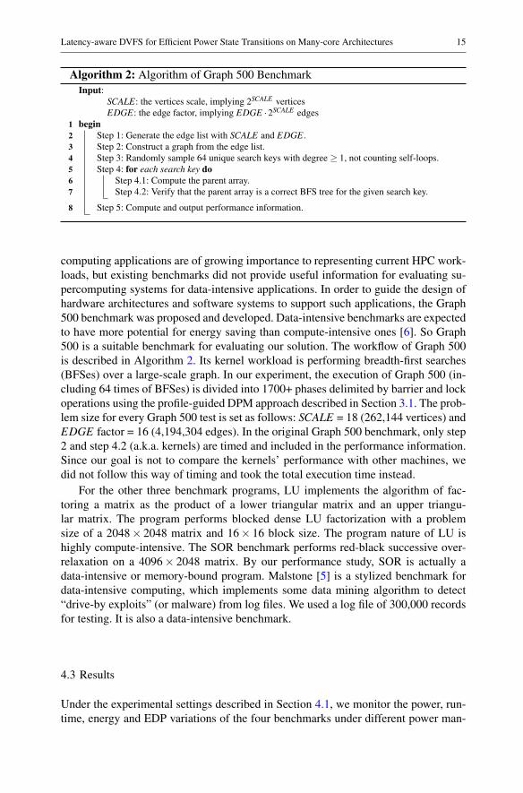
Algorithm 2: Algorithm of Graph 500 BenchmarkInput:
SCALE: the vertices scale, implying 2SCALE verticesEDGE: the edge factor, implying EDGE ·2SCALE edges
1 begin2 Step 1: Generate the edge list with SCALE and EDGE.3 Step 2: Construct a graph from the edge list.4 Step 3: Randomly sample 64 unique search keys with degree ≥ 1, not counting self-loops.5 Step 4: for each search key do6 Step 4.1: Compute the parent array.7 Step 4.2: Verify that the parent array is a correct BFS tree for the given search key.
8 Step 5: Compute and output performance information.
computing applications are of growing importance to representing current HPC work-loads, but existing benchmarks did not provide useful information for evaluating su-percomputing systems for data-intensive applications. In order to guide the design ofhardware architectures and software systems to support such applications, the Graph500 benchmark was proposed and developed. Data-intensive benchmarks are expectedto have more potential for energy saving than compute-intensive ones [6]. So Graph500 is a suitable benchmark for evaluating our solution. The workflow of Graph 500is described in Algorithm 2. Its kernel workload is performing breadth-first searches(BFSes) over a large-scale graph. In our experiment, the execution of Graph 500 (in-cluding 64 times of BFSes) is divided into 1700+ phases delimited by barrier and lockoperations using the profile-guided DPM approach described in Section 3.1. The prob-lem size for every Graph 500 test is set as follows: SCALE = 18 (262,144 vertices) andEDGE factor = 16 (4,194,304 edges). In the original Graph 500 benchmark, only step2 and step 4.2 (a.k.a. kernels) are timed and included in the performance information.Since our goal is not to compare the kernels’ performance with other machines, wedid not follow this way of timing and took the total execution time instead.
For the other three benchmark programs, LU implements the algorithm of fac-toring a matrix as the product of a lower triangular matrix and an upper triangu-lar matrix. The program performs blocked dense LU factorization with a problemsize of a 2048× 2048 matrix and 16× 16 block size. The program nature of LU ishighly compute-intensive. The SOR benchmark performs red-black successive over-relaxation on a 4096× 2048 matrix. By our performance study, SOR is actually adata-intensive or memory-bound program. Malstone [5] is a stylized benchmark fordata-intensive computing, which implements some data mining algorithm to detect“drive-by exploits” (or malware) from log files. We used a log file of 300,000 recordsfor testing. It is also a data-intensive benchmark.
4.3 Results
Under the experimental settings described in Section 4.1, we monitor the power, run-time, energy and EDP variations of the four benchmarks under different power man-

16 Zhiquan Lai et al.
Table 4 Results of average power, runtime, energy and EDP obtained during benchmark program execu-tions under different power management policies. The items with * are values normalized to the static800Mfigures
Static800M Latency-Unaware
Latency-Aware
Max-VSLatecy
Graph 500
AvgPower (W) 69.62 21.79 21.54 36.20Runtime (s) 365.51 692.35 535.17 481.07Energy (J) 25446.73 15086.84 11527.81 17416.17EDP (kJs) 9301.04 10445.36 6169.33 8378.41AvgPower* 1.0000 0.3130 0.3094 0.5200Runtime* 1.0000 1.8942 1.4642 1.3162Energy* 1.0000 0.5929 0.4530 0.6844EDP* 1.0000 1.1230 0.6633 0.9008
LU
AvgPower (W) 88.03 32.13 30.88 33.02Runtime (s) 32.74 71.35 33.86 66.00Energy (J) 2882.02 2292.57 1045.69 2179.34EDP (kJs) 94.36 163.58 35.41 143.83AvgPower* 1.0000 0.3650 0.3508 0.3751Runtime* 1.0000 2.1793 1.0342 2.0158Energy* 1.0000 0.7955 0.3628 0.7562EDP* 1.0000 1.7336 0.3753 1.5243
SOR
AvgPower (W) 85.39 34.42 33.19 75.81Runtime (s) 81.86 84.69 84.22 84.95Energy (J) 6989.73 2914.60 2795.43 6440.37EDP (kJs) 572.17 246.83 235.42 547.12AvgPower* 1.0000 0.4031 0.3887 0.8879Runtime* 1.0000 1.0345 1.0288 1.0378Energy* 1.0000 0.4170 0.3999 0.9214EDP* 1.0000 0.4314 0.4114 0.9562
Malstone
AvgPower (W) 90.16 37.24 27.91 38.36Runtime (s) 62.11 63.66 73.09 63.65Energy (J) 5599.97 2370.53 2040.19 2441.66EDP (kJs) 347.82 150.91 149.12 155.41AvgPower* 1.0000 0.4130 0.3096 0.4255Runtime* 1.0000 1.0250 1.1768 1.0248Energy* 1.0000 0.4233 0.3643 0.4360EDP* 1.0000 0.4339 0.4287 0.4468
agement policies. The results are shown in Table 4. Note that the results were obtainedwith the optimization target towards minimal EDP as described in Section 3.
In Table 4, “Runtime” denotes the total execution time of the benchmark program.“AvgPower” refers to the average chip power of the SCC, including the power of theCPU cores and the network-on-chip (NoC). “Energy” is the energy consumption of thechip during the execution, i.e. the product of average power and runtime, and “EDP”is the product of energy and runtime. We also present the results (the items markedwith *) normalized to the corresponding values of static800M. For ease of visualizingthe comparison, we plot the normalized values of runtime, average power, energy andEDP as histograms as shown in Fig. 4.
From the experimental results of Graph 500 (Fig. 4(a)), we can see that all thethree policies using DVFS achieved big savings in energy or EDP compared with thestatic power mode. Although the baseline profile-guided power management policy

Latency-aware DVFS for Efficient Power State Transitions on Many-core Architectures 17
(latency-unaware) achieves 40.7% energy saving, it gives the worse EDP result. Thelatency-aware policy achieves 54.7% energy saving and 33.7% EDP reduction. Thatmeans, our latency-aware DVFS algorithm achieves 23.6% and 40.9%, respectively,more energy and EDP savings than the latency-unaware policy. This is indeed the bestresult—a win-win case—that proves the effectiveness of our latency-aware DVFSalgorithm from both energy and performance viewpoints. The max-VSlatency pol-icy achieves 31.6% energy saving and 9.9% EDP reduction compared with the staticpower scheme. This implies much potential for energy saving in data-intensive appli-cations exemplified by Graph 500. Compared with max-VSLatency, our latency-awarealgorithm reduces the energy and EDP further by 33.8% and 26.4% respectively. Thisconfirms that our latency-aware DVFS algorithm is more capable of improving theDVFS efficiency than what Ioannou et al. [15] proposed.
For the LU benchmark (Fig. 4(b)), although the three power management policiesusing DVFS can all reduce the average power and energy significantly (average reduc-tion of 63.2% and 28.1% respectively), only the latency-aware policy reduces the EDPproduct (by 62.5%). On the contrary, the other two polices, latency-unaware and max-VSLatency, give the worst EDP figures (increased by 73.4% and 52.4% respectively)due to substantial performance loss.
For the SOR benchmark (Fig. 4(c)), the latency-aware policy performs better thanother policies in all aspects, including average power, runtime, energy and EDP (al-though the improvements over the latency-unaware policy are marginal for this pro-gram). Compared with static800M, it has 60.0% energy saving and 58.9% EDP re-duction, outperforming the max-VSLatency policy by saving 56.6% more energy andgiving 57.0% better EDP without observable performance degradation.
For Malstone (Fig. 4(d)), we can see all the three DVFS schemes can achievesignificant energy saving and EDP reduction. But our latency-aware DVFS schemeachieves the least EDP as desired (57.2% less than the static policy’s EDP) despite the17.7% runtime increase it costs.
In summary, compared with the static mode (static800M), our latency-aware DVFSalgorithm achieves 51.2% average EDP reduction (with 55.3% average energy saving)while the average overhead of execution time is 8.8%. Compared with the latency-unaware policy, it gives 31.3% EDP reduction, 24.0% energy saving and 15.2% lessoverhead of execution time in the average case. It also wins over the DVFS solution ofIoannou et al. [15] by an average of 42.5% further reduction in EDP and 44.9% moreenergy saving.
4.4 Analysis and Discussion
We further analyze and discuss the experimental results by linking to observationsabout the chip power variation (Fig. 5) during the execution of the benchmark pro-grams.
4.4.1 Analysis of Graph 500
Figure 5(a) shows the chip power of the SCC when Graph 500 was run under differentpower management policies. For the first 13 seconds in the figure, the performance

18 Zhiquan Lai et al.
0
0.5
1
1.5
2
Static800M Latency-Unaware Latency-Aware Max-VSLatency
Nor
mal
ized
val
ue
AvgPower*Runtime*Energy*
EDP*
(a) Graph 500
0
0.5
1
1.5
2
2.5
Static800M Latency-Unaware Latency-Aware Max-VSLatency
Nor
mal
ized
val
ue
AvgPower*Runtime*Energy*
EDP*
(b) LU
0
0.5
1
1.5
2
Static800M Latency-Unaware Latency-Aware Max-VSLatency
Nor
mal
ized
val
ue
AvgPower*Runtime*Energy*
EDP*
(c) SOR

Latency-aware DVFS for Efficient Power State Transitions on Many-core Architectures 19
0
0.5
1
1.5
2
Static800M Latency-Unaware Latency-Aware Max-VSLatency
Nor
mal
ized
val
ue
AvgPower*Runtime*Energy*
EDP*
(d) Malstone
Fig. 4 Results of average power, runtime, energy and EDP of the benchmarks running under different powermanagement policies. The values are normalized to the static800M figures
and power obtained under different policies are nearly the same. This is because theprogram is performing compute-intensive edge generation and graph construction inthat time range, where the opportunity for power saving is very limited (so, high powersetting was applied). Beyond this range, the program begins to perform breadth-firstsearches and the workload becomes more data-intensive (or memory-bound), so DPMpolicies get opportunities to lower the power with little performance loss. With ourproposed latency-aware DVFS algorithm, the DPM solution effectively avoids mostof the excessive long-latency voltage transitions. So the algorithm achieves better run-time performance. We can also see that both latency-unaware and max-VSLatencypolicies are making the chip power jump up and drop down aggressively with longspikes in the figure. However, the latency-aware policy makes the power variationmore stable, lingering in the low power range of around 20 to 30 watts.
The results obtained have confirmed that aggressive power state transitions will re-ally translate into either sizable slowdown in runtime or increase in average chip powerconsumption. Although the max-VSLatency policy tries to avoid excessive voltagetransitions by putting a fixed time gap between DVFS scheduling reference points, itmay make wrong decisions that allow non-profitable power state transitions to hap-pen while omitting those profitable ones. This is also why the chip power stays in thehigher-power region most of the time for max-VSLatency in Figure 5(a). We can con-jecture that it must have missed quite a lot of rewarding transitions from high-power tolow-power states. Therefore, compared with our latency-aware policy, although max-VSLatency gets an 11.2% performance improvement (or 10.1% runtime reduction), itconsumes 68.1% more average power.
Analysis of the Phase-based Profiles: Since our baseline DPM scheme follows aprofile-guided approach, we present the execution profile of Graph 500 to figure outthe correlation between the profile and DVFS scheduling. The profiles of the Graph500 benchmark with and without latency-awareness are shown in Fig. 6. The profilesinclude the optimal power setting (V/ f pair) for each phase. It is quite common in

20 Zhiquan Lai et al.
10
20
30
40
50
60
70
80
90
0 100 200 300 400 500 600 700
Pow
er (
Wat
t)
Time (s)
Static800MLatency-Unaware
Latency-AwareMax-VSLatency
(a) Graph 500
20
40
60
80
100
0 10 20 30 40 50 60 70 80
Pow
er (
Wat
t)
Time (s)
Static800MLatency-Unaware
Latency-AwareMax-VSLatency
(b) LU
20
40
60
80
100
0 10 20 30 40 50 60 70 80 90
Pow
er (
Wat
t)
Time (s)
Static800MLatency-Unaware
Latency-AwareMax-VSLatency
(c) SOR

Latency-aware DVFS for Efficient Power State Transitions on Many-core Architectures 21
20
40
60
80
100
0 10 20 30 40 50 60 70 80
Pow
er (
Wat
t)
Time (s)
Static800MLatency-Unaware
Latency-AwareMax-VSLatency
(d) Malstone
Fig. 5 Chip power comparison during execution under different power management policies
0 100 200 300 400 500 600 700 800 900
1000
0 200 400 600 800 1000 1200 1400 1600 1800
Freq
uenc
y (M
Hz)
Phase #
Optimal frequency setting guided by the profile for each phase (Latency-Unaware)
Latency-Unaware/core0 Latency-Unaware/core1
0 100 200 300 400 500 600 700 800 900
1000
0 200 400 600 800 1000 1200 1400 1600 1800
Freq
uenc
y (M
Hz)
Phase #
Optimal frequency setting guided by the profile for each phase (Latency-Aware)
Latency-Aware/core0 Latency-Aware/core1
Fig. 6 Comparison of the profiles with and without the latency-aware algorithm: in the upper sub-figure,we can find some aggressive DVFS decisions which cause power state transitions between different voltagelevels (referring to Table 3, frequencies of 800MHz, 533MHz and other values below 533MHz imply differ-ent corresponding voltages). After applying the latency-aware algorithm, we can see in the lower sub-figurethat these aggressive state transitions have disappeared.
SVM programming styles that the master process exhibits an execution pattern some-what different from other processes of the same parallel program. For example, themaster process usually takes up the duties of reading the input data file, allocating a

22 Zhiquan Lai et al.
shared array for all cores to access, and printing the aggregated computation result.We assume the master process is always running on core 0 and all “non-master” pro-cesses share a very similar execution pattern. In Fig. 6, “core0” and “core1” in thelegend denote the profiles of the master process and the processes running on othercores respectively.
The top sub-figure of Fig. 6 shows the profile information derived without thelatency-aware algorithm. The x-axis represents the phase number; the y-axis standsfor the optimal frequency (MHz) for the corresponding phase. As described in Sec-tion 4.1, the least voltage for 800MHz is 1.1V; for 533MHz, it is 0.9V; and for otherfrequency levels under 533MHz, it is 0.8V. We can see in the figure that there existmany excessive DVFS scheduling decisions due to the lack of latency awareness. Forexample, beyond the phase #210 or so, there are many times of frequency scalingamong different voltage levels, which could cause high voltage switching costs.
We expect the latency-aware DVFS algorithm proposed in Section 3 can avoidsuch excessive DVFS decisions. The bottom sub-figure of Fig. 6 shows the profileof Graph 500 obtained with our latency-aware algorithm enabled. We can see thatthere are much fewer DVFS decisions made among different voltage levels after ap-plying the algorithm. The DVFS decisions become more “conservative” in the caseswhen voltage scaling is needed. This proves that our proposed algorithm is capable ofchoosing the most profitable power states to switch between when the temporal effectsof voltage scaling are considered.
4.4.2 Analysis of LU
The chip power variation of the LU program execution is depicted in Fig. 5(b). Theexecution is divided into 524 phases by barriers and locks. In the figure, it is obvi-ous that the execution times obtained by the latency-unaware and max-VSLatencypolicies both increase to over a double of that obtained by the latency-aware policy.Meanwhile, the power maintained using these two policies is quite unstable, fluctu-ating fairly vigorously between 30 and 50 watts. By comparing the DVFS decisions,we find that the latency-unaware scheme keeps switching the power state frequentlybetween different voltage levels (0.9V and 0.8V). As we investigated in Section 2,such voltage scaling has a high latency cost to pay. Frequent voltage transitions arethe cause for the dismal performance and additional energy dissipation observed inFig. 4(b). Although the max-VSLatency policy avoids some of the excessive powerstate transitions and performs slightly better than the latency-unaware policy, its powerefficiency is much worse than the latency-aware policy.
4.4.3 Analysis of SOR
Figure 5(c) displays the chip power consumed by the SOR program during its exe-cution. We can see that enabling DVFS basically causes no increase in runtime, nomatter which policy is used. By inspecting the profile of this benchmark, we findthat the main portion of execution from about the 20th second to the end correspondsto a single phase performing a sorting procedure which is highly memory-bound innature—up to 98% bus utilization is noted during our performance monitoring. That
Latency-aware DVFS for Efficient Power State Transitions on Many-core Architectures 23
means for such data-intensive workload, we can slow down the frequency and/or volt-age to save energy with vanishingly small performance loss. This is also observable inFig. 4(c)—all the runtime bars are almost the same. Another interesting phenomenonobserved is that the max-VSLatency policy starts failing to make power reduction af-ter the 20th second. This is because the policy finds that the coming frequency/voltagescaling is not far away enough from the last scaling. So it skips the scaling request. Byonly one inaccurate decision, it sacrifices the vast opportunity to save power for thelong-running phase. This again implies that the strategy of moving DVFS schedulingdecisions far apart by a universal gap would be overkill. On the other hand, we cansee that both latency-aware and latency-unaware policies perform quite alike for thisbenchmark. This is because the entire execution of SOR has nine phases only—theroom is too small for latency-aware DVFS scheduling to exploit for significant im-provements to be observed. This contrasts with the very different situation of the LUprogram execution which has hundreds of phases.
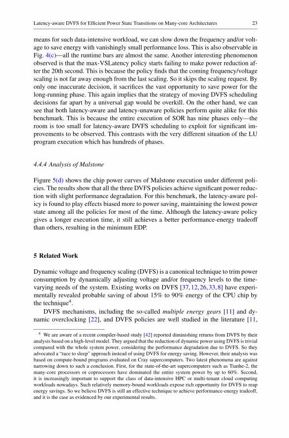
4.4.4 Analysis of Malstone
Figure 5(d) shows the chip power curves of Malstone execution under different poli-cies. The results show that all the three DVFS policies achieve significant power reduc-tion with slight performance degradation. For this benchmark, the latency-aware pol-icy is found to play effects biased more to power saving, maintaining the lowest powerstate among all the policies for most of the time. Although the latency-aware policygives a longer execution time, it still achieves a better performance-energy tradeoffthan others, resulting in the minimum EDP.
5 Related Work
Dynamic voltage and frequency scaling (DVFS) is a canonical technique to trim powerconsumption by dynamically adjusting voltage and/or frequency levels to the time-varying needs of the system. Existing works on DVFS [37,12,26,33,8] have experi-mentally revealed probable saving of about 15% to 90% energy of the CPU chip bythe technique4.
DVFS mechanisms, including the so-called multiple energy gears [11] and dy-namic overclocking [22], and DVFS policies are well studied in the literature [11,
4 We are aware of a recent compiler-based study [42] reported diminishing returns from DVFS by theiranalysis based on a high-level model. They argued that the reduction of dynamic power using DVFS is trivialcompared with the whole system power, considering the performance degradation due to DVFS. So theyadvocated a “race to sleep” approach instead of using DVFS for energy saving. However, their analysis wasbased on compute-bound programs evaluated on Cray supercomputers. Two latest phenomena are againstnarrowing down to such a conclusion. First, for the state-of-the-art supercomputers such as Tianhe-2, themany-core processors or coprocessors have dominated the entire system power by up to 60%. Second,it is increasingly important to support the class of data-intensive HPC or multi-tenant cloud computingworkloads nowadays. Such relatively memory-bound workloads expose rich opportunity for DVFS to reapenergy savings. So we believe DVFS is still an effective technique to achieve performance-energy tradeoff,and it is the case as evidenced by our experimental results.
24 Zhiquan Lai et al.
15,23,30,31,21]. Freeh et al. presented a power-efficient execution framework us-ing multiple frequency-voltage settings [11]. Ma et al. adopted control theory to pre-cisely control the power of the entire many-core chip [23]. David et al. demonstrateda power management algorithm that runs in real time and dynamically adjusts the per-formance of islands of cores to reduce power consumption while maintaining the samelevel of performance [7]. Li et al. presented a software-controlled execution schemethat considers the effects of dynamic concurrency throttling (DCT) and dynamic volt-age/frequency scaling (DVFS) in the context of hybrid programming models [21]. Loand Kozyrakis [22] studied the power-performance impact of CPU TurboMode andproposed autoturbo to dynamically manage TurboMode for modern multicore chips.However, all these pieces of work did not explore the latency behavior of DVFS, eventhough their evaluations were conducted on real multicore hardware platforms.
This paper fills the research gap by developing a novel DVFS algorithm that coun-teracts the side effects of the scaling latency. The direct inspiration for this papercomes from our study of the DVFS latency characteristics on a many-core chip. Wefound that the latency is non-negligible and varies case by case, calling for a moreintelligent DVFS scheduling algorithm to counteract its adverse effects. Some priorworks did reveal the potential problem with DVFS latency [27,28,41,15]. They arediscussed as follows.
Ravishankar et al. argued that if fine-grained DVFS support is provided, the over-heads of DVFS would scale with the number of cores in the multiprocessor system-on-chip (MPSoC) platforms [28]. There also exist a few research efforts related tocombating the DVFS overhead issue. For instance, thread motion [27] or thread mi-gration [28] was introduced into DPM schemes to reduce the DVFS overhead. Rav-ishankar et al. proposed a power-aware thread migration algorithm to dynamicallymigrate threads to appropriate cores with different and static power states. However,thread migration could make the execution environment much more complex.
Ye et al. [41] proposed reducing the number of power state transitions by introduc-ing task allocation into learning-based dynamic power management for multicore pro-cessors. However, program execution pattern usually changes according to the work-flow so that the optimal power settings for each phase of program execution are likelyto be different. Although task allocation reduces the time of DVFS scaling, it couldalso cause misses of important power saving opportunities.
Finally, Ioannou et al. [15] proposed a hierarchical DVFS controller using somephase prediction algorithm for MPI applications. We feel that their work is the closestto ours—both adopted a phase-based hierarchical power management approach andused the Intel SCC hardware for experimental evaluation. But we did the work forshared-memory programs (on Barrelfish) while they targeted MPI programs (evalu-ated on SCC Linux). In their solution, they are also aware of the non-negligible volt-age transition costs. They try to amortize the costs by making the reference points forDVFS scheduling decisions far apart. Their study found that a DVFS decision affect-ing the whole chip can take up to 6ms, and employed an empirical threshold of at least20ms between the reference points. Our study, on the other hand, reveals that the over-head can surge to over 200ms in the worst case that all voltage domains of the busychip are making concurrent voltage scaling requests, and suggests a more intelligent,fine-grained algorithm segregating scale-up and scale-down scenarios. Our previous

Latency-aware DVFS for Efficient Power State Transitions on Many-core Architectures 25
work [18] investigated DVFS latency behavior and proposed a preliminary version oflatency-aware DVFS for many-core architectures. In this paper, we extend it in twomain aspects. First, we improved our DVFS algorithm by considering the impact ofbusy-waiting phases on DVFS scaling; the very details of the algorithm (Section 3)are supplemented in this paper. Second, we provided a more thorough experimentalcomparison between our improved algorithm and the threshold-based method givenby Ioannou et al. [15]. Our novel DVFS control algorithm is proved to work better inall cases for a better balance between performance and energy.
6 Conclusion
In this paper, we investigate the latency characteristics of DVFS for many-core archi-tectures with multiple voltage domains. We find non-negligible DVFS latency on theIntel SCC many-core architecture. Based on the study, a latency-aware DVFS controlalgorithm is proposed to avoid excessive power state transitions. We implement thealgorithm into a working DVFS controller for the Barrelfish operating system plusa power management library for (virtual) shared-memory parallel programs. A thor-ough experimental evaluation using Graph 500, along with other benchmarks, wasconducted on the Intel SCC platform. The experimental results show that our latency-aware DVFS algorithm is capable of achieving 15.2% less execution time, 24.0% moreenergy saving and 31.3% better EDP in the average case than a baseline profile-guideddynamic power management (DPM) policy without latency awareness. The algorithmalso performs better than a prior DVFS scheme employing a universal time gap be-tween DVFS scheduling decisions to amortize heavy voltage scaling costs.
Acknowledgments This work is supported by Hong Kong RGC grant HKU 716712E, Program for Chang-jiang Scholars and Innovative Research Team in University (PCSIRT, No. IRT1012) and Aid Program forScience and Technology Innovative Research Team in Higher Educational Institutions of Hunan Province(No. 11JJ7003). Special thanks go to Intel China Center of Parallel Computing (ICCPC) and Beijing SoftTech Technologies Co., Ltd. for providing us their support services of the SCC platform in their Wuxi datacenters.
References
1. Top500 List - June 2014. URL http://www.top500.org/lists/2014/06/2. SCC external architecture specification (EAS) (revision 0.94). Tech. rep., Intel Labs (2010)3. The SCC programmer’s guide (revision 1.0). Tech. rep., Intel Labs (2010)4. Baumann, A., Barhamy, P., Dagandz, P.E., Harrisy, T., Isaacsy, R., Peter, S., Roscoe, T., Schüpbach, A.,
Singhania, A.: The multikernel: A new OS architecture for scalable multicore systems. In: Proceedingof ACM Symposium on Operating System Principles (SOSP) (2009)
5. Bennett, C., Grossman, R.L., Locke, D., Seidman, J., Vejcik, S.: Malstone: towards a benchmark foranalytics on large data clouds. In: Proceedings of the 16th ACM SIGKDD international conference onKnowledge discovery and data mining, pp. 145–152. ACM, 1835826 (2010)
6. Cameron, K.W., Ge, R., Feng, X.: Designing computational clusters for performance and power. Ad-vances in Computers 69, 89–153 (2007)
7. David, R., Bogdan, P., Marculescu, R., Ogras, U.: Dynamic power management of voltage-frequencyisland partitioned networks-on-chip using Intel’s single-chip cloud computer. In: Proceeding of Inter-national Symposium on Networks-on-Chip (NOCS), pp. 257–258 (2011)

26 Zhiquan Lai et al.
8. Donald, J., Martonosi, M.: Techniques for multicore thermal management: Classification and new ex-ploration. In: Proceeding of ACM/IEEE International Symposium on Computer Architecture (ISCA),pp. 78–88 (2006)
9. Fahey, J.: Home electricity use in US falling to 2001 levels (2013). URL http://bigstory.ap.org/article/home-electricity-use-us-falling-2001-levels
10. Feng, W.C., Cameron, K.: The Green500 list: Encouraging sustainable supercomputing. Computer40(12), 50–55 (2007). DOI http://doi.ieeecomputersociety.org/10.1109/MC.2007.445
11. Freeh, V.W., Lowenthal, D.K.: Using multiple energy gears in mpi programs on a power-scalable clus-ter. In: Proceedings of the tenth ACM SIGPLAN symposium on Principles and practice of parallelprogramming, pp. 164–173. ACM (2005)
12. Govil, K., Chan, E., Wasserman, H.: Comparing algorithm for dynamic speed-setting of a low-powerCPU. In: Proceedings of the 1st Annual International Conference on Mobile Computing and Network-ing (MobiCom), pp. 13–25. ACM, 215546 (1995)
13. Graph500: The Graph 500 benchmark. URL http://www.graph500.org14. Howard, J., Dighe, S., Vangal, S., Ruhl, G., Borkar, N., Jain, S., Erraguntla, V., Konow, M., Riepen,
M., Gries, M., Droege, G., Lund-Larsen, T., Steibl, S., Borkar, S., De, V., Wijngaart, R.V.D.: A 48-core IA-32 message-passing processor in 45nm CMOS using on-die message passing and DVFS forperformance and power scaling. IEEE Journal of Solid-State Circuits 46(1), 173–183 (2011)
15. Ioannou, N., Kauschke, M., Gries, M., Cintra, M.: Phase-based application-driven hierarchical powermanagement on the single-chip cloud computer. In: Proceeding of the 20th International Conferenceon Parallel Architectures and Compilation Techniques (PACT) (2011)
16. Iyer, A., Marculescu, D.: Power efficiency of voltage scaling in multiple clock, multiple voltage cores.In: Proceedings of the 2002 IEEE/ACM International Conference on Computer-aided Design, ICCAD’02, pp. 379–386. ACM, New York, NY, USA (2002). DOI 10.1145/774572.774629. URL http://doi.acm.org/10.1145/774572.774629
17. Lai, Z., Lam, K.T., Wang, C.L., Su, J.: A power modeling approach for many-core architectures.In: Proceedings of the 10th International Conference on Semantics, Knowledge and Grids, SKG ’14(2014). (in press)
18. Lai, Z., Lam, K.T., Wang, C.L., Su, J., Yan, Y., Zhu, W.: Latency-aware dynamic voltage and frequencyscaling on many-core architectures for data-intensive applications. International Conference on CloudComputing and Big Data (CloudCom-Asia) (2013)
19. Lam, K.T., Shi, J., Hung, D., Wang, C.L., Yan, Y., Zhu, W.: Rhymes: A shared virtual memory sys-tem for non-coherent tiled many-core architectures. In: Proceedings of the 20th IEEE InternationalConference on Parallel and Distributed Systems, ICPADS ’14 (2014). (in press)
20. Li, B., Chang, H.C., Song, S.L., Su, C.Y., Meyer, T., Mooring, J., Cameron, K.: The power-performancetradeoffs of the Intel Xeon Phi on HPC applications. In: Workshop on Large-Scale Parallel Processing,LSPP ’14 (2014)
21. Li, D., Supinski, B.R.d., Schulz, M., Nikolopoulos, D.S., Cameron, K.W.: Strategies for energy-efficient resource management of hybrid programming models. IEEE Trans. Parallel Distrib. Syst.24(1), 144–157 (2013)
22. Lo, D., Kozyrakis, C.: Dynamic management of turbomode in modern multi-core chips. 20th Interna-tional Symposium on High Performance Computer Architecture (HPCA) (2014)
23. Ma, K., Li, X., Chen, M., Wang, X.: Scalable power control for many-core architectures running multi-threaded applications. In: Proceeding of ACM/IEEE International Symposium on Computer Architec-ture (ISCA) (2011)
24. Matthews, O., Zhang, M., Sorin, D.: Scalably verifiable dynamic power management. In: Proceedingsof the 20th IEEE International Symposium on High Performance Computer Architecture, HPCA ’14,pp. 579–590 (2014). DOI 10.1109/HPCA.2014.6835967
25. National Energy Administration (NEA) of China: China’s total electricity consumption in 2013. URLhttp://www.nea.gov.cn/2014-01/14/c_133043689.htm
26. Qingyuan, D., Meisner, D., Bhattacharjee, A., Wenisch, T.F., Bianchini, R.: Coscale: CoordinatingCPU and memory system DVFS in server systems. In: Proceeding of the 45th Annual IEEE/ACMInternational Symposium on Microarchitecture (MICRO), pp. 143–154 (2012)
27. Rangan, K.K., Wei, G.Y., Brooks, D.: Thread motion: Fine-grained power management for multi-coresystems. ACM/IEEE International Symposium on Computer Architecture (ISCA) (2009)
28. Ravishankar, C., Ananthanarayanan, S., Garg, S., Kennings, A.: Analysis and evaluation of greedythread swapping based dynamic power management for mpsoc platforms. 13th International Sympo-sium on Quality Electronic Design (ISQED) (2012)

Latency-aware DVFS for Efficient Power State Transitions on Many-core Architectures 27
29. Rotem, E., Mendelson, A., Ginosar, R., Weiser, U.: Multiple clock and voltage domains for chip multiprocessors. In: Proceedings of the 42nd Annual IEEE/ACM International Symposium on Microarchi-tecture, MICRO 42, pp. 459–468. ACM, New York, NY, USA (2009). DOI 10.1145/1669112.1669170.URL http://doi.acm.org/10.1145/1669112.1669170
30. Sartori, J., Kumar, R.: Proactive peak power management for many-core architectures. Tech. Rep.CRHC-07-04, University of Illinois at Urbana-Champaign (2007)
31. Simone, D.: Power management in a manycore operating system. Masters thesis (2009)32. Sinkar, A., Ghasemi, H., Schulte, M., Karpuzcu, U., Kim, N.S.: Low-cost per-core voltage domain
support for power-constrained high-performance processors. IEEE Transactions on Very Large ScaleIntegration (VLSI) Systems 22(4), 747–758 (2014). DOI 10.1109/TVLSI.2013.2257900
33. Sueur, E.L., Heiser, G.: Dynamic voltage and frequency scaling: the laws of diminishing returns. In:Proceedings of the 2010 International Conference on Power Aware Computing and Systems, pp. 1–8(2010)
34. Talpes, E., Marculescu, D.: Toward a multiple clock/voltage island design style for power-aware pro-cessors. IEEE Transactions on Very Large Scale Integration (VLSI) Systems 13(5), 591–603 (2005).DOI 10.1109/TVLSI.2005.844305
35. Trader, T.: China’s supercomputing strategy called out (2014). URL http://www.hpcwire.com/2014/07/17/dd/
36. Vogeleer, K.D., Memmi, G., Jouvelot, P., Coelho, F.: The energy/frequency convexity rule: Modelingand experimental validation on mobile devices. In: R. Wyrzykowski, J. Dongarra, K. Karczewski,J. Wasniewski (eds.) Parallel Processing and Applied Mathematics, Lecture Notes in Computer Sci-ence, pp. 793–803. Springer Berlin Heidelberg (2014). DOI 10.1007/978-3-642-55224-3_74
37. Weiser, M., Welch, B., Demers, A., Shenker, S.: Scheduling for reduced CPU energy. In: Proceedingof the 1st USENIX Conference on Operating Systems Design and Implementation (OSDI) (1994)
38. Weissel, A., Bellosa, F.: Process cruise control: Event-driven clock scaling for dynamic power man-agement. In: Proceeding of the International Conference on Compilers, Architecture and Synthesis forEmbedded Systems (CASES) (2002)
39. Wilson, L.: Average household electricity use around the world. URL http://shrinkthatfootprint.com/average-household-electricity-consumption
40. World Population Review: China population 2014. URL http://worldpopulationreview.com/countries/china-population
41. Ye, R., Xu, Q.: Learning-based power management for multi-core processors via idle period manipu-lation. In: Proceeding of the 17th Asia and South Pacific Design Automation Conference (ASP-DAC),pp. 115–120 (2012)
42. Yuki, T., Rajopadhye, S.: Folklore confirmed: Compiling for speed = compiling for energy. In: Pro-ceedings of the 26th International Workshop on Languages and Compilers for Parallel Computing,LCPC ’13 (2013)