laser tracking and tram control of a continuous …stacks.cdc.gov/view/cdc/10570/cdc_10570_ds1.pdfri...
TRANSCRIPT

RI 9319 REPORT OF INVESTIGATIONS/1990
PLEASE 00 Nor REMOVE FRCM LIBRARY
Laser Tracking and Tram Control of aContinuous Mining Machine
By Donna L. Anderson
1910* 80 * 1990YEARS
BUREAU OF MINES
UNITED STATES DEPARTMENT OF THE INTERIOR

~.s. Bureau of Mines ~
Spokane Resenrch CenterE ".- R~ •
. ".I.;) l;,omc;o;-,-!sry Ave.Srl,~~!n"l" \'./n\ [,,,ro?! ~ ....... J .• , J I J .... ,J __
Ll ~ ~~~r.~(i
Mission: As the Nation's principal conservationagency, the Department of the Interior has responsibility for most of our nationally-owned publiclands and natural and cultural resources. Thisincludes fostering wise use of our land and waterresources, protecting our fish and wildlife, preserving the environmental and cultural values ofour national parks and historical places, and providing for the enjoyment of life through outdoorrecreation. The Department assesses our energyand mineral resources and works to assure thattheir development is in the best interests of allour people. The Department also promotes thegoals of the Take Pride in America campaign byencouraging stewardship and citizen responsibility for the public lands and promoting citizen participation in their care. The Department also hasa major responsibility for American Indian reservation communities and for people who live inIsland Territories under U.S. Administration.

Report of Investigations 9319
Laser Tracking and Tram Control of aContinuous Mining Machine
By Donna L. Anderson
UNITED STATES DEPARTMENT OF THE INTERIORManuel lUjan, Jr., Secretary
BUREAU OF MINEST S Ary, Director
Library of Congress Cataloging in Publication Data:
Anderson, Donna L.Laser tracking and tram control of a continuous mining machine / by Donna L.
Anderson.
p. cm. - (Report of investigations; 9319)
Includes bibliographical references.
Sup!. of Docs. no.: 128.23:9319.
1. Mining machinery-Automatic control. 2. Mine railroads-Automatic control.3. Navigation-Data processing. 4. Optical scanners. I. Title. II. Series: Reportof investigations (United States. Bureau of Mines); 9319.
TN23.U43 [TN345] 622s-dc20 [622'.028] 90-2094 elP

CONTENTSPage
Abstract. . . . . . . . . . . . . . . . . . . . . . . . . . . . . . . . . . . . . . . . . . . . . . . . . . . . . . . . . . . . . . . . . . . . . . . . . . . 1Introduction . . . . . . . . . . . . . . . . . . . . . . . . . . . . . . . . . . . . . . . . . . . . . . . . . . . . . . . . . . . . . . . . . . . . . . . . 2System hardware 3
Laser-scanning sensors and retroreflective targets 4RS-485 communication network 6Sun workstation 6TAMME and BITBUS distributed control network 6
System software .... . . . . . . . . . . . . . . . . . . . . . . . . . . . . . . . . . . . . . . . . . . . . . . . . . . . . . . . . . . . . . . . . . 6Position and heading computation module. . . . . . . . . . . . . . . . . . . . . . . . . . . . . . . . . . . . . . . . . . . . . . . . 6
System initialization 7Lasernet data acquisition 7Angular coordinate error compensation. . . . . . . . . . . . . . . . . . . . . . . . . . . . . . . . . . . . . . . . . . . . . . . . 7Position and heading updates 8
Tram control module 8Safety checking on tram commands. . . . . . . . . . . . . . . . . . . . . . . . . . . . . . . . . . . . . . . . . . . . . . . . . . . 8Closed-loop tram control 8Interface to AMREDS . . . . . . . . . . . . . . . . . . . . . . . . . . . . . . . . . . . . . . . . . . . . . . . . . . . . . . . . . . . . 8
Test results 10Lasernet dust gallery experiments .. . . . . . . . . . . . . . . . . . . . . . . . . . . . . . . . . . . . . . . . . . . . . . . . . . . . . 10Angular coordinate accuracy test . . . . . . . . . . . . . . . . . . . . . . . . . . . . . . . . . . . . . . . . . . . . . . . . . . . . . . . 11
Angular test procedure . . . . . . . . . . . . . . . . . . . . . . . . . . . . . . . . . . . . . . . . . . . . . . . . . . . . . . . . . . . . 11Range test procedure . . . . . . . . . . . . . . . . . . . . . . . . . . . . . . . . . . . . . . . . . . . . . . . . . . . . . . . . . . . . . 12Error compensation algorithms. . . . . . . . . . . . . . . . . . . . . . . . . . . . . . . . . . . . . . . . . . . . . . . . . . . . . . 12
Position and heading tracking and tram control accuracy . . . . . . . . . . . 12Conclusions 13
ILLUSTRATIONS
1. Laser scanners on reference structure viewing targets on continuous mining machine . . . . . . . . . . . . . . . 22. Three targets in field-of-view of single laser 33. Two same targets in field-of-view of two lasers . . . . . . . . . . . . . . . . . . . . . . . . . . . . . . . . . . . . . . . . . . . 34. Lasernet guidance system components 45. Lasernet laser-scanning sensor with retroreflective targets . . . . . . . . . . . . . . . . . . . . . . . . . . . . . . . . . . . 56. Two Lasernet units on MCS mockup viewing three targets on Joy 16CM . . . . . . . . . . . . . . . . . . . . . . . . 57. Lasernet position and heading computation module 78. Tram control module. . . . . . . . . . . . . . . . . . . . . . . . . . . . . . . . . . . . . . . . . . . . . . . . . . . . . . . . . . . . . . 99. Lasernet control of Joy 16CM using AMREDS interface. . . . . . . . . . . . . . . . . . . . . . . . . . . . . . . . . . . . 10
10. Effect of target angular coordinate on Lasernet accuracy before and after correction 1111. Effect of target range on Lasernet accuracy 12
TABLES
1. Dust test results 102. Error correction test results . . . . . . . . . . . . . . . . . . . . . . . . . . . . . . . . . . . . . . . . . . . . . . . . . . . . . . . . . 123. Lasernet tracking and tram control results 13

UNIT OF MEASURE ABBREVIATIONS USED IN THIS REPORT
deg degree ms millisecond
ft foot pct percent
in inch rjs revolution per second
m meter s second
mgjm3 milligram per cubic meter

LASER TRACKING AND TRAM CONTROL OFA CONTINUOUS MINING MACHINE
By Donna L. Anderson1
ABSTRACT
This U.S. Bureau of Mines report discusses the status of a laser-based guidance system to provideposition and heading feedback and closed-loop control of tramming maneuvers for a continuous miningmachine. The system has been developed and tested at the Bureau, and is now being prepared forunderground experiments. The system hardware includes laser scanners, a sensor communication network, and host computer hardware. The system software includes a position and heading computationmodule and a tram control module. The description of the software includes discussions of laser dataacquisition, error compensation methods, position and heading determination, safety checking for continuous miner tramming, and closed-loop tram control. The accuracy of the laser scanner's data, thereliability of the lasers in a dusty environment, and the system's accuracy on tracking the position andheading of the continuous mining machine are shown in the results of experiments performed at theBureau. Conclusions are stated based on these experimental results, and further work to improve thesystem performance and prepare for underground testing is discussed.
'Electrical engineer, Pittsburgh Research Center, U.S. Bureau of Mines, Pittsburgh, PA.
2
INTRODUCTION
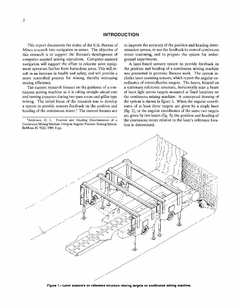
This report documents the status of the U.S. Bureau ofMines research into navigation in mines. The objective ofthis research is to support the Bureau's development ofcomputer-assisted mining operations. Computer-assistednavigation will support the effort to relocate mine equipment operators further from hazardous areas. This will result in an increase in health and safety, and will provide amore controlled process for mining, thereby increasingmining efficiency.
The current research focuses on the guidance of a continuous mining machine as it is taking straight-ahead cutsand turning crosscuts during two-pass room-and-pillar typemining. The initial focus of the research was to developa system to provide sensory feedback on the position andheading of the continuous miner.2 The current focuses are
2Anderson, D. L. Position and Heading Determination of aContinuous Mining Machine Using an Angular Position-Sensing System.BuMines IC 9222, 1989, 8 pp.
to improve the accuracy of the position and heading determination system, to use the feedback to control continuousminer tramming, and to prepare the system for underground experiments.
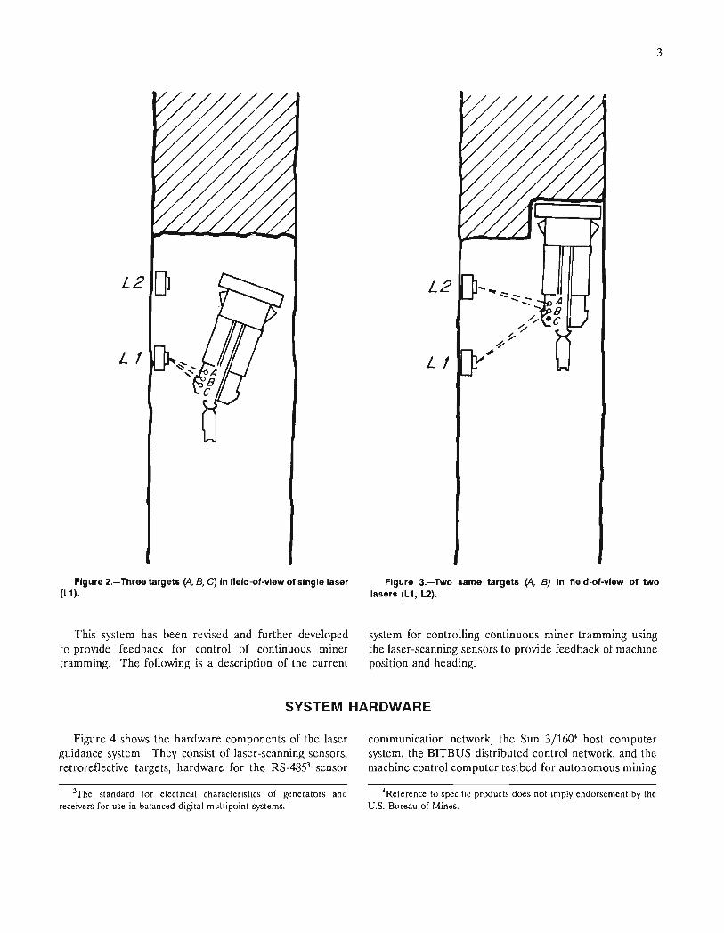
A laser-based sensory system to provide feedback onthe position and heading of a continuous mining machinewas presented in previous Bureau work. The system includes laser-scanning sensors, which report the angular coordinates of retroreflective targets. The lasers, located ona stationary reference structure, horizontally scan a beamof laser light across targets mounted at fixed locations onthe continuous mining machine. A conceptual drawing ofthe system is shown in figure 1. When the angular coordinates of at least three targets are given by a single laser(fig. 2), or the angular coordinates of the same two targetsare given by two lasers (fig. 3), the position and heading ofthe continuous miner relative to the laser's reference location is determined.
Figure 1.--t.aser scanners on reference structure viewing targets on continuous mining machine.
L2 OJ
L I
Figure 2.-Three targets (A, B, C) In f1eld-of-vlew of single laser(L1).
This system has been revised and further developedto provide feedback for control of continuous minertramming. The following is a description of the current
3
L2
L I
Figure 3.-Two same targets (A, B) In f1eld-of-vlew of twolasers (L1, L2).
system for controlling continuous miner tramming usingthe laser-scanning sensors to provide feedback of machineposition and heading.
SYSTEM HARDWARE
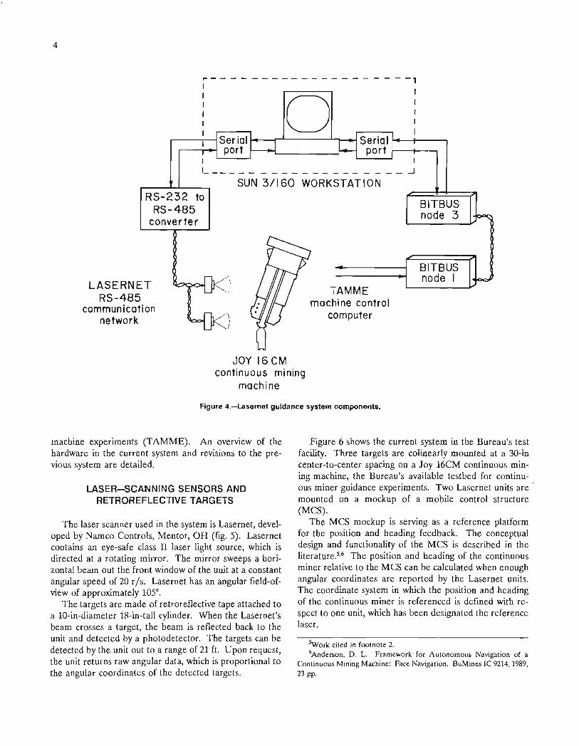
Figure 4 shows the hardware components of the laserguidance system. They consist of laser-scanning sensors,retroreflective targets, hardware for the RS-48.9 sensor
~e standard for electrical characteristics of generators andreceivers for use in balanced digital multipoint systems.
communication network, the Sun 3/16Q'l host computersystem, the BITBUS distributed control network, and themachine control computer testbed for autonomous mining
4Reference to specific products does not imply endorsement by theU.S. Bureau of Mines.
4
r----------------
o- -,
IIII
I
I I'- ...J
SUN 3/160 WORKSTATIONRS-232 to
RS-485converter
BITBUSnode 3
TAMMEmachine control
computer
LASERNETRS-485
communicationnetwork
JOY 16 eMcontinuous mining
machine
BITBUSnode I
Figure 4.-lasernet guidance system components.
machine experiments (TAMME). An overview of thehardware in the current system and revisions to the previous system are detailed.
LASER-5CANNING SENSORS ANDRETROREFLECTIVE TARGETS
The laser scanner used in the system is Lasernet, developed by Namco Controls, Mentor, OR (fig. 5). Lasernetcontains an eye-safe class II laser light source, which isdirected at a rotating mirror. The mirror sweeps a horizontal beam out the front window of the unit at a constantangular speed of 20 r/s. Lasernet has an angular field-ofview of approximately 105°.
The targets are made of retroreflective tape attached toa lO-in-diameter 18-in-tall cylinder. When the Lasernet'sbeam crosses a target, the beam is reflected back to theunit and detected by a photodetector. The targets can bedetected by the unit out to a range of 21 f1. Upon request,the unit returns raw angular data, which is proportional tothe angular coordinates of the detected targets.
Figure 6 shows the current system in the Bureau's testfacility. Three targets are colinearly mounted at a 3D-incenter-to-center spacing on a Joy 16CM continuous mining machine, the Bureau's available testbed for continuous miner guidance experiments. Two Lasernet units are .mounted on a mockup of a mobile control structure(MCS).
The MCS mockup is serving as a reference platformfor the position and heading feedback. The conceptualdesign and functionality of the MCS is described in theliterature.5•6 The position and heading of the continuousminer relative to the MCS can be calculated when enoughangular coordinates are reported by the Lasernet units.The coordinate system in which the position and headingof the continuous miner is referenced is defined with respect to one unit, which has been designated the referencelaser.
SWork cited in footnote 2.6Anderson, D. L. Framework for Autonomous Navigation of a
Continuous Mining Machine: Face Navigation. BuMines Ie 9214,1989,23 pp.
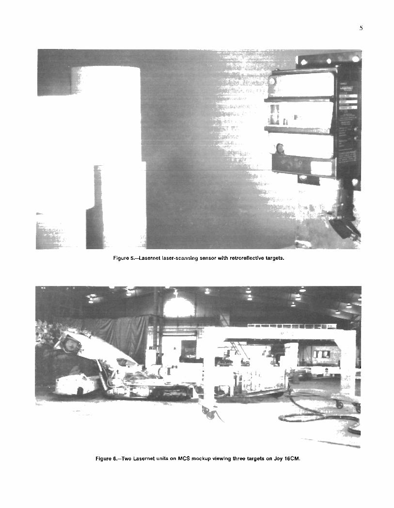
Figure 5.-Lasernet laser-scanning sensor with retroreflectlve targets.
Figure 6.-Two Lasernet units on MCS mockup viewing three targets on Joy 16CM.

6
RS-485 COMMUNICATION NETWORK
Raw angular data from the Lasernet units are requestedby and delivered to the host computer over a RS-485 communication network. The RS-485 network replaced theRS-232 communications used earlier so that multipleLasernet units can be addressed on one communicationline, and to increase the length of transmission line andthe noise tolerance. The new system takes advantage ofthe two-wire balanced differential signals and the multidrop features of RS-485 communications. All Lasernetunits are attached to common send and receive lines.Transmission lines as long as 1,200 m are possible. Also,the host computer now requires only a single RS-232serial port, which is tied into the network via a RS-232 toRS-485 interface converter developed by Namco Controls.
Each Lasernet unit on the network is assigned a uniqueaddress. The format and content of the requests from thehost computer are the same as the previous RS-232-basedsystem, except that an address precedes the request. Allunits on the netWork always operate in a passive listeningmode and receive the request; however, only the one unitspecifically addressed will respond.
Communication errors are detected by the host computer through the monitoring of a checksum provided byLasernet. These errors can occur if multiple units wereaddressed and trying to respond. Lasernet has a variablecommunication response time, which is managed by thehost computer to avoid any situation where a data collisioncould occur.
SUN WORKSTATION
A Sun 3/160 workstation is currently functioning asthe host computer, and is being used for the software development of the system. The Sun's programming includes a position and heading computation module and atram control module. The modules are coded in the "C"
programming language, and run under the UNIX operating system.
The UNIX environment was used for the formation ofthis navigational software because it is a superb system forsoftware development. However, it was not intended to beused as the fmal operating system for continuous minertram control. UNIX lacks many features of real-time control systems, such as quick and predictable interrupt response, fast task context switching, and the ability to attacheasily tasks (software) to interrupts (hardware). On theother hand, UNIX offers many advantages that make it auseful part of a distributed real-time system. For thesereasons, the position and heading and tram control software will be directly loaded to a single-board microcomputer system that runs a real-time, UNIX compatibleoperating system. This new system will allow compatibilitywith the Sun-UNIX environment, portability for in-mineexperiments, and most importantly, real-time control oftramming.
TAMME AND BITBUS DISTRIBUTEDCONTROL NETWORK
TAMME, the on-board machine control computer,executes the Joy 16CM functions requested by the Sun'stram control module. TAMME has been programmed toaccept Joy 16CM commands in the form of packets ofdigital information, decode the information, and actuatethe appropriate functions on the Joy 16CM. When thefunction has been successfully actuated, TAMME returnsan acknowledgment to the Sun.
The Sun workstation and TAMME communicate overthe BITBUS distributed control network through BITBUSnodes. Commands and acknowledgments are coded in theBOMNET machine command protocol developed by theBureau for the Joy 16CM. The BOMNET protocol,BITBUS network, and TAMME are documented in theliterature.7
SYSTEM SOFTWARE
The current software on the Sun includes a position andheading computation module and a tram control module.These modules are described in the following sections.
POSITION AND HEADING COMPUTATIONMODULE
The pOSItion and heading computation module consists of routines for initialization of Lasernet and target
parameters of the system, acqUlSltion of Lasernet rawangular data, compensation of Lasernet angular coordinates errors, and calculation of position and heading.Figure 7 shows the order of processing.
7Schiffbauer, W. H. A Microcomputer Network for AutonomousMining Research. Ch. 85 in Proceedings of 21st International Symposium on Application of Computers and Operations Research inthe Mineral Industry, ed. by A. Weiss. Soc. Min. Eng., AlME, 1989,pp. 928-935.

7
Figure 7.-lasernet position and heading computation module.
System Initialization
The system initialization routine reads a data file forsystem startup parameters. The data file includes information on Lasernet units and retroreflective targets. Foreach Lasernet unit, the data file includes the laser's location in the entry, field-of-view, range, communicationsaddress, error correction information, and polling status(indicating whether the unit is connected and active on thesystem, or a spare to be used at another time). For each
Angular Coordinate Error Compensation
The data acquisition routine polls each Lasernet unitthat is connected and operational on the RS-485 networkand gathers the raw angular data. The routine also includes timeouts in the event of communication failures,disposal af any garbage data on the network, verifieschecksums, and allows the option to take repetitive readsand average raw angular data to smooth out any erraticdata.
The routine sequences through the list of lasers generated by the system initialization routine. If a laser isactive, it reads the laser's address and sends a request forthat laser's data in the form of "#," "address," and "<cr>".If no response is obtained in 60 ms, it is assumed that acommunication failure has occurred and goes to the nextactive Lasernet. If a response is received, the routinelooks for a valid data packet. Any garbage data are discarded until good data are received or no more datawere returned. The routine verifies the data packet witha checksum comparison. Finally, the valid raw angulardata are converted to radians and the angular coordinateis stored in memory.
Lasernet Data Acquisition
target, the data file includes the target's location relativeto the machine center.
This routine makes the system easily reconfigurable tosuit different guidance tasks. To add or remove a particular Lasernet unit, the user changes the laser polling status; to relocate a unit, the user enters its new location.The other Lasernet parameters, such as field-of-view,range, communications address, and error correction datawould be altered if a new unit is added to the system. Ifthe targets were relocated on the machine, the user wouldalso enter the new target locations relative to machinecenter.
A compensation algorithm for angular coordinate errorsis utilized once all angular coordinates have been acquiredfrom a Lasernet. Extensive tests done at the Bureau onone of the units proved that the errors are a repeatablefunction of two parameters; the angular and the radial coordinates of the target.
These two parameters used by the error compensationalgorithm are easily determined. The approximate angularcoordinate of the target is given from the Lasernet unit.A trigonometric algorithm estimates the radial coordinate using two other angular coordinates given by thesame Lasernet. The parameter values are then used bythe error compensation algorithm to correct the angularcoordinate, and the compensated angular coordinate isstored in memory. The test procedures, accuracy test
Systeminitialization
Lasernetdata acquisition
Position andheading updates
Angular coordinateerror compensation
}
To tramcontrol module
~ ~
Read laserdata file ...-
1Acquire raw angular
data fromlaser network ...-
.+Convert raw data toangular coordinates
(radians)
.~Estimate target
radial coordinate
••Determinecompensated
angular coordinate
••Calculate positionand heading
I laser - 3 angle2laser- 2 angle ...-
.+Average valuesand store result
1/
~
8
results, and the error compensation algorithm are described in detail in the Test Results section of this report.
Position and Heading Updates
The continuous miner's position and heading is calculated using the compensated angular coordinates. Two algorithms are employed and are documented in detail inthe literature.8 One algorithm calculates position andheading based on the compensated angular coordinates ofthree targets from one Lasernet unit, and the other on thecoordinates of the same two targets from two Lasernetunits.
When more than the minimum compensated angularcoordinates for determination of position and heading areavailable, multiple determinations are computed. Thesemultiple position and heading determinations are averagedtogether. Updates of continuous miner position and heading are provided five times per second.
TRAM CONTROL MODULE
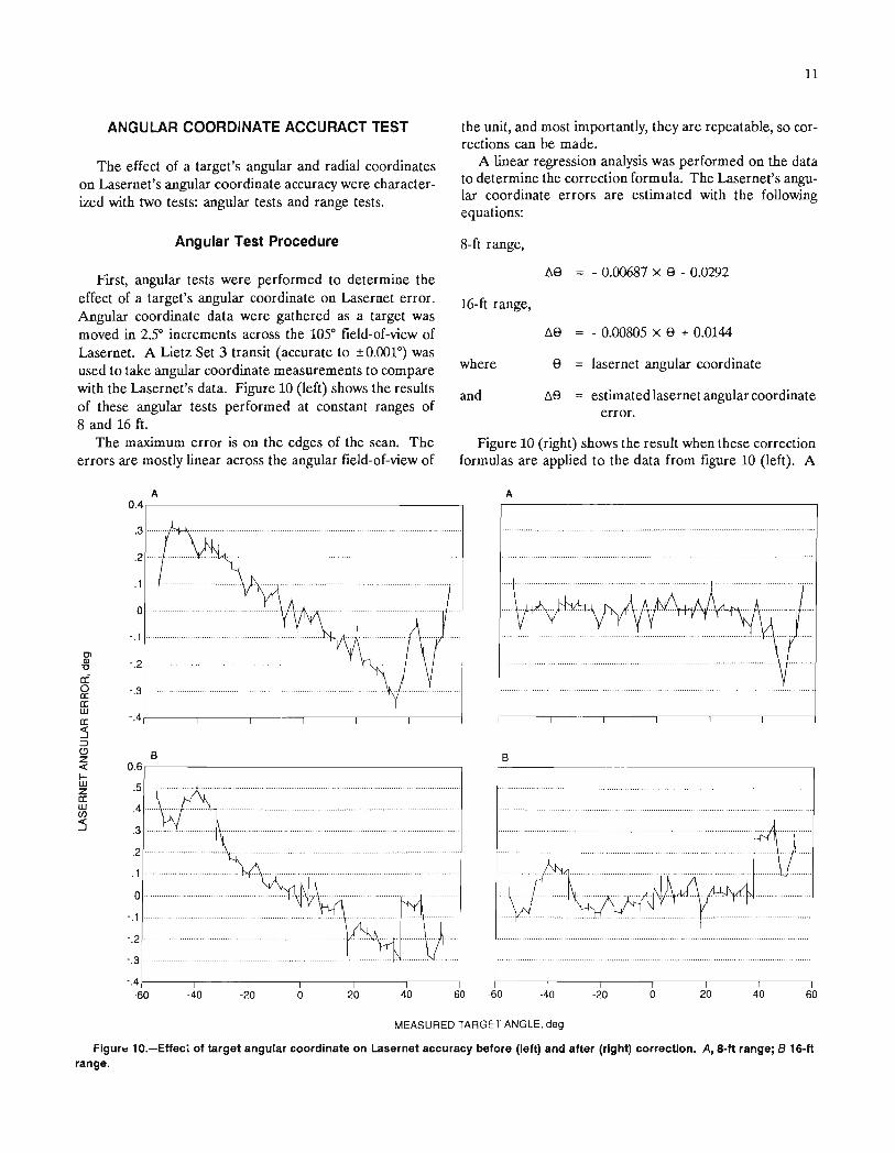
The tram control module consists of routines forchecking the safety of requested tram commands beforethey are issued, monitoring the laser's position and heading updates to effect closed-loop control of Joy 16CMtramming, and interfacing to the Autonomous Mining Research and Development System (AMREDS) to utilize itsuser, graphical, and machine interface facilities. Figure 8shows the order of processing.
Safety Checking on Tram Commands
The safety checking routine uses the machine's positionand heading determinations to check the safety of each requested tram command, and, if determined safe, it issuesthe command to the machine. These safeguards are essential because computer-assisted operations will allow thecontinuous miner operator to be located farther away fromthe face, thereby limiting the operator's vision of the facearea.
Tram commands are requested and delivered to thesafety checking routine via the AMREDS tram controlmenu (described in the Interface to AMREDS section ofthis report). A command is depicted as a Joy 16CM tramming option with a target value. Continuous miner tramming options include tram forward (both tracks forward,high or low speed), tram reverse (both tracks reverse, highor low speed), pivot (one track forward, one track reverse,low speed), turn forward (one track forward), and turn reverse (one track reverse). The target values are expressedin inches or degrees.
8Work cited in footnote 2.
When a new tram command is requested, the safetychecking routine first predicts the destination position andheading of the machine, and then checks for any potentially hazardous situations. The frrst check determineswhether the machine would hit any Lasernet units whiletramming to the destination. Because the continuousminer is in close quarters with the Lasernet units, thissafeguard is essential. Secondly, a check is made to determine if the command will result in the targets going outof the lasers' detectable range. In this situation, theposition and heading of the continuous miner wouldbecome unknown, and the tram command cannot be controlled properly. Finally, a check is made to see whetherthe machine will hit the ribs. Although there are no sensors to indicate the precise location of the ribs, an estimatecan be obtained from the Lasernet system's position. Sincethe Lasernet is initially placed in the entry with its positioncalibrated relative to the mine plan, it can define two lines,i.e., the presumed location of the rib, and 20 ft (or anydesignated distance) away, the location of a parallel rib.These estimated locations are used by the safety routine tocheck if the machine would hit the ribs.
Any tram commands determined safe are issued to themachine. Any dangerous commands will not be executed,and a warning will be sent back to the user via AMREDS.
Closed-Loop Tram Control
The closed-loop control algorithm controls machinetranslational and rotational movements. Once a tramcommand has been determined safe and issued to the machine, this routine monitors the position and headingfeedback from the Lasernet system, and issues a stop tramwhen the target value of the tram command has beenachieved.
The actuation delays associated with a stop tram foreach tramming option have been measured on our Joy'16CM. To improve control precision, a stop tram is issuedearly to compensate for these delays. For example, astop command issued during a pivot left command has atime lag of 0.46 s. The angular velocity of a pivot left is3.230° per second. Therefore, the rotational lag is 1.49°.During a command such as pivot left 10°, a stop tram willbe issued when the machine has rotated 8.51°. The Joy16CM actuation delays and tram velocities are documentedin the literature.9
Interlace to AMREDS
AMREDS was designed by Carnegie Mellon University,Pittsburgh, PA, under a Bureau contract for supporting
9Sammarco, J. J. Closed Loop Control for a Continuous MiningMachine. BuMines Rl 9209, 1988, 17 pp.

9
-------,
Automaticmachine skit
executor
IIIIIII------_.1
User selectablemachine
command menu
r---------I AMREDS
IIIIIIL _
Yes
No
Send stop tramto machine
Check compensationfor machine
actuation delays
r - - - - - - - - - - - - - - --,I
--.J
°0::IZ
°oa..8,--.J
roW(/)
go
No
Send commandto machine
Yes
Send warningto AMREDS
(9
z~ Check safetyw of the command::r:o
From position andheading computation -------..,
module
r - - - - - - - - - - - - - - .- - ---
Calcu late resu Itantmachine position
and heading
>IWu..<1:(/)
oZ<1:,~,
~,
0,0,
~I
<1:10::,1-,,
I,I,I,I,l. _
---- ....,AMREDS I
III
_.J
IIIIL _
To pos itionand headingcomputation
module
Figure 11.-Tram control module.
10
Figure 9.-lasernet control of Joy 16CM using AMREDSInterface.
net work interface
~ t
AMREDS
AMREDSuser Interface
Pos,t Ion and heading
computation module
and
tram conlrol module
o0.
o."'"(f)
O::::t P<==J
TAMME machine control computer
BITBUS network
Lasernet network
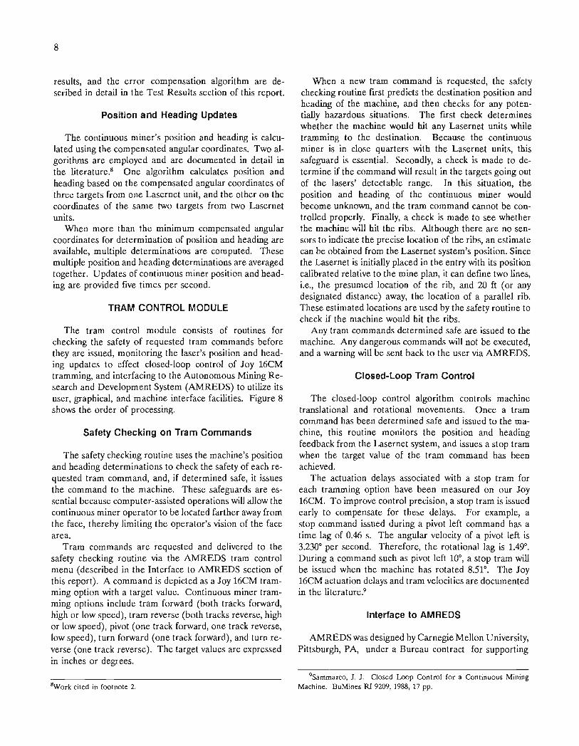
continuous miner automation research. Through the interface to AMREDS, the continuous miner guidance systemhas access to many useful routines that facilitate softwaredevelopment. The AMREDS user interface includes atram control menu for easy selection of tram commandsand a sensor-driven graphical display of the Joy 16CMcontinuous miner in an entry. A BITBUS network interface routine in AMREDS converts the machine commandsissued by the safety checking routine into packets ofdigital information, and issues them onto the BITBUSdistributed control network to be actuated by TAMME.The AMREDS skit executor mode allows a user to compose, edit, and execute a sequence of continuous minercommands.
Figure 9 shows how the Lasernet data processing andtram control software fit into AMREDS. Tram commandsare either selected from the tram control menu by a user,or read from a script automatically by the skit executor.The tram control module receives the tram command, analyzes it to determine whether it is a safe command, andsends the safe command to the BITBUS network interface,which forwards the commands to TAMME.
The updates of machine position and heading are produced by the position and heading computation module,monitored by the tram controller, and are also deliveredto the AMREDS graphical display, providing remote visualfeedback of the movement and location of the machine inthe entry.
TEST RESULTS
Experiments have been performed on the Lasernet system to improve its effectiveness and characterize itsperformance for tram control of a continuous mining machine in the mine environment. The reliability of Lasernetin a dusty environment was tested. The accuracy of Lasernet's angular coordinate reports was determined and usedin the formation of error correction equations to increasethe accuracy of the position and heading determinations.Also, the system's accuracy in tracking the position andheading of the continuous miner was determined.
LASERNET DUST GALLERY EXPERIMENTS
at which the Lasernet can detect and accurately report theangular coordinate of the target.
Table 1 shows the results of the tests. The respirabledust level dictated by Mine Safety and Health Adminis- .tration (MSHA) requirements is 2 mg/m3
• The Lasernet'sangular coordinate reports are extremely reliable up to aconcentration of 13 mg/m3
• Since the targets will be located at the back of the machine, and the Lasernet unitswill most often be located outbye the targets, dust is expected to have little effect on the Lasernet's ability todetect targets.
Table 1.-Dust test results
The effect of dust concentration on the Lasernet's ability to detect targets was tested in the experimental dustgallery at the Bureau. A target was placed in the field-ofview of a Lasernet unit at a range of 12 ft. Three dustmonitors were located so they could sample the dust alongthe path from the Lasernet to the target.
Data from the dust monitors were correlated to datafrom the Lasernet to determine the maximum level of dust
Dust concentration,mg/m3
oto 5 .5 to 10 .10 to 15 .15t02O .20 to 25 .
Target-in-viewtime, pet
10096.276.215o
11
ANGULAR COORDINATE ACCURACT TEST
The effect of a target's angular and radial coordinateson Lasernet's angular coordinate accuracy were characterized with two tests: angular tests and range tests.
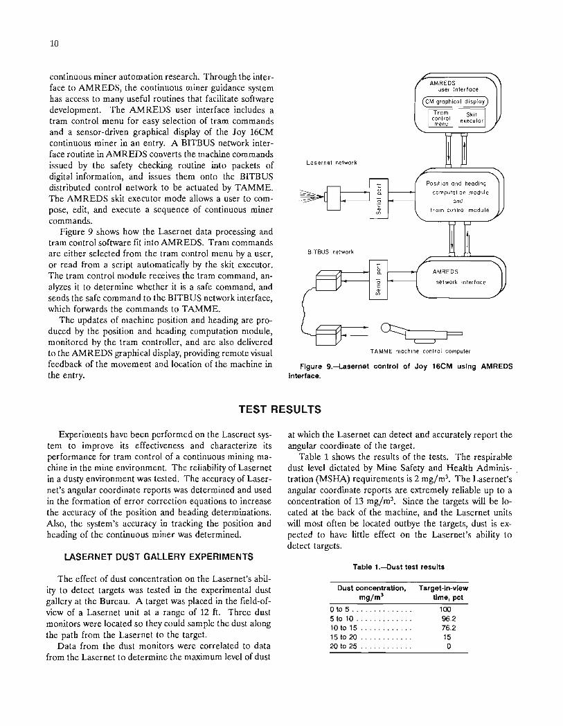
the unit, and most importantly, they are repeatable, so corrections can be made.
A linear regression analysis was performed on the datato determine the correction formula. The Lasernet's angular coordinate errors are estimated with the followingequations:
Angular Test Procedure 8-ft range,
6.8 - 0.00687 x 8 - 0.0292
16-ft range,
Figure 10 (right) shows the result when these correctionformulas are applied to the data from figure 10 (left). A
6.8 - 0.00805 x 8 + 0.0144
lasernet angular coordinate
estimated lasernet angular coordinateerror.
8
6.S
where
and
First, angular tests were performed to determine theeffect of a target's angular coordinate on Lasernet error.Angular coordinate data were gathered as a target wasmoved in 2S increments across the 105° field-of-view ofLasernet. A Lietz Set 3 transit (accurate to ±O.cXW) wasused to take angular coordinate measurements to comparewith the Lasernet's data. Figure 10 (left) shows the resultsof these angular tests performed at constant ranges of8 and 16 ft.
The maximum error is on the edges of the scan. Theerrors are mostly linear across the angular field-of-view of
A A
604020o-20-40
B
60 -604020
0
-.1
OlQl -.2··"0
a:0 -.3a:a:w -.4a::5::JCJ Bzc:( 0.6I-w .5za:w(J)
:5 .3
.2
.1 ..
0
-.1
-.2··
-.3··
-.4-60 -40 -20 0
0.4,---------------------,
MEASURED TARGET ANGLE, deg
Flgur.. 10.-Effeci of target angular coordinate on Lasernet accuracy before (left) and after (right) correction. A, 8-ft range; B 16-ftrange.

12
±0.15° error is maintained over most of the field-of-viewof the unit. The worst case was a 0.3° error on the edgeof the scan.
Range Test Procedure
The effect of a target's radial coordinate on Lasernet'sangular coordinate accuracy was determined in a secondseries of tests. Figure 11 shows the results of one of thesetests. A target was placed in the field-of-view of aLasernet unit at a constant angular coordinate. The targetwas then moved throughout the range of the Lasernetfrom 3 to 21 ft.
Analysis of all the range experiments showed that theLasernet's accuracy was only slightly affected by range upto 10 ft, with an error of ±0.05°. The worst errors,approximately 0.2°, were found at ranges of 15 and 21 ft.
ranges of 10 and 16 ft, a linear interpolation between the8- and 16-ft formulae is used; at ranges of greater than16 ft, only the 16-ft formula is used. Lasernet's angularcoordinate is then adjusted by this estimated error to yielda compensated angular coordinate.
Spot tests were performed to check the success ofthis error correction method. A target was randomlyplaced in the range and angular field-of-view of the unit.Transit measurements of the target's angular coordinateswere compared with the Lasernet's compensated angularcoordinates. Table 2 shows the results of these tests. Theoverall errors reported by the Lasernet unit were reducedby 53 pct, and each range region shows a significantamount of error correction.
Table 2.-Error correction test results
Error Compensation Algorithms farget rangeAverage error, degBefore After
correction correction
Error correction,
pet
Figure 11.-EHect of target range on Lasernet accuracy.
An algorithm to compensate for the repeatable errorswas developed based on the results of the angular andrange tests. This algorithm requires two input variables;i.e., the target's angular coordinate and the target's radialcoordinate. An estimation of the target's angular coordinate is given directly from the Lasernet unit, and an estimation of radial coordinate is calculated using two otherangular position reports from the same Lasernet unit.
The error compensation algorithm uses the formulaedetermined in the angular test procedure to estimate theLasernet angular coordinate error. At ranges less than10 ft, the 8-ft error correction formula is used; between
MEASURED TARGET RANGE, ft
58.86038.153.1
0.17 0.07.25 .10.21 .13.21 .10
Less than or equal to 10ftBetween 10 and 16 ft .Greater than or equal to 16 ft
Overall , .
The reduction in target angular coordinate errors isvery significant since these errors induce machine positionand heading errors. When propagated through the position and heading algorithms, errors in target angular coordinates will, on average, double in machine headingerrors. For example, a 0.2° error in a target's angularcoordinate will, on average, result in a 0.4° error in theheading determination. The position determination is lessaffected; nevertheless, a 0.2° error in a target angularcoordinate would result in an average of 0.2° in error inposition. Average position and heading errors are statedbecause there are many factors that affect the propagationof angular coordinate errors. A primary factor influencingerror propagation is the distance to the targets.
POSITION AND HEADING TRACKING ANDTRAM CONTROL ACCURACY
The precision of the position and heading computationmodule in tracking, and the tram control module in controlling Joy 16CM translations and rotations were tested.A series of tram commands were issued to the Joy 16CMand, at the completion of each command, transit data weregathered and compared with the updates from the positionand heading computation module.
201510
0.4OlQ)
D
a: .30a:a:
.2UJa::5::J .1(')z«f-- o·UJza:UJCIl -.1····:5
- .20 5

13
Table :J.-t.asernet tracking and tram control test results
CommandTargetvalve,
in
Translation, inTransit Lasernet
measure- reportment
Error, inLasernet Tramtracking control
CommandTargetvalue,deg
Rotation, deg Error, degTransit Lasernet Lasernet Tram
measure- report tracking controlment
Tram forward .. 40 38.88 40.63 -1.75 1.12 Pivot left . .... 7 7.44 6.79 0.65 -0.4448 46.52 49.79 -3.28 1.48 9 9.08 9.18 -.11 -.0836 34.04 35.17 -1.13 1.96 Pivot right .... 5 4.70 4.39 .31 .0334 31.78 35.35 -3.57 2.22 Turn forward
right ....... 4.5 4.41 4.39 .02 .09Tram reverse .. 48 47.18 50.11 -2.93 .82 Turn reverse
24 22.57 24.43 -1.86 1.43 right ....... 4 3.38 3.74 .14 .1236 35.38 37.40 -2.02 .6232.5 30.80 33.90 -3.10 1.7030 28.32 31.98 -3.66 1.68
Table 3 shows the results of the first series of tests.Each tram command listed was issued three times andthe data averaged. Tracking results showed an average2.59 in. error in translation, and an average 0.25° error inheading. Tram control results showed an average 1.45 in.error in translation, and an average 0.21° error in heading.
Both the tracking and tram control results are promising; however, the tram control results are inconclusive.
Since a real-time computer is not yet being used for control, the actual control precision is not yet shown withthese data. Further experiments will be conducted to further prove the tracking accuracy, and the tram control precision will be tested when the real-time computer systemis operational.
CONCLUSIONS
The status of a system to provide position and headingfeedback and closed-loop control of tramming maneuversfor a continuous mining machine has been described. Thesystem includes Lasernet laser-scanning sensors, whichreport the angular coordinates of three retroreflectivetargets. The Lasernet sensors are mounted on a referencestructure, and the Lasernet targets are mounted onboardthe continuous mining machine. The machine position andheading computation and tram control modules are programmed on a Sun 3/160 workstation, and include routines for Lasernet data acquisition, error compensation,position and heading determination, safety checking forcontinuous miner tramming, and closed-loop tram control.
Dust tests on the Lasernet sensor demonstrated thatdust in the face area would pose little, if any, restrictionson system reliability. The results of tests on a Lasernet'sangular coordinate accuracy is used in an algorithm for error compensation, which maintains a ±O.lSO target angularposition accuracy over most of the 21 ft range and lOYangular field-of-view of the sensor. The systems accuracy
in tracking the pOSItIOn and heading of a continuousmining machine was also investigated, and errors werefound on average to be 0.25° in heading and 2.59 in. inposition.
The system has been developed and tested at theBureau on a Joy 16CM continuous mining machine. Anupdate of the position and heading of the continuousminer is provided approximately five times per second.The system allows a user to select tram commands withtarget values from a tramming menu, which will then beexecuted by the continuous miner. This system is beingprepared for underground experiments.
Further work to improve the system performance andprepare for underground testing is planned. The positionand heading computation and tram control module willbe loaded to a real-time computer system to allow formore precise and reliable real-time tram control andportability for in-mine experiments. Further experimentswill be conducted at that time to determine the system'sperformance.
INT.BU.OF MINES,PGH.,PA 29215