laser marking at a glance - trumpf
TRANSCRIPT
↑CONTENT
Laser marking at a glance

↑CONTENT
Laser marking at a glance
Marking lasers perform more
and more tasks in the industry.
In this manual, you can
find out what role marking lasers
play in the different sectors.
You will learn about the technical
background of processes as
well as laser systems and receive
a guide to practical marking.
APPLICATION AREAS AND SECTORS
TR ACEABIL IT Y
CUSTOMIZATION AND DESIGN
PROCESS PREPARATION AND SURFACE TREATMENT
MEDIC AL TECHNOLOGY
AUTOMOTIVE
ELEC TRONICS
WHITE GOODS AND CONSUMER GOODS
BASICS OF LASER MARKING
METAL
PL ASTICS
OTHER NONMETALS
NATUR AL MATERIALS
PROCESS PAR AMETERS
L ASER
BEAM GUIDANCE AND FOCUSING
MARKING SYSTEMS
PROCESS REL IABIL IT Y
PRACTICAL MARKING
DEFINING THE MARKING CONTENT
ALIGNING THE POSIT ION
SELEC TING THE PAR AMETERS
DEFINING THE PROCESSES
MARKING
CHECKING QUALIT Y AND READABIL IT Y
APPLIC ATION SUPPORT AND SERVICE
1
1.1
1.2
1.3
1.4
1.5
1.6
1.7
2
2.1
2.2
2.3
2.4
2.5
2.6
2.7
2.8
2.9
3
3.1
3.2
3.3
3.4
3.5
3.6
3.7
↑CONTENT

↑CONTENT
↑CONTENT
1. APPLICATION AREAS AND SECTORS
Nowadays, it is becoming more and more common for industrial markings to be applied
with a marking laser. Lasers have established themselves as the marking tool of choice in
industry, as they are contactless, highly flexible, easy to integrate, and produce perfect
quality. From higher traceability requirements through to the raw materials, counterfeit
protection, customized products and the desire to acquire a component that functions as
its own data carrier in a smart factory — these are all trends that argue in favor of
marking lasers.
It doesn’t end there. The application spectrum of pulsed or marking lasers already
extends far beyond just marking components; these tools are now conquering new terrain
in process preparation and surface treatment.
Laser marking stands out when compared with conventional marking methods due
to quite a number of advantages, which is why it has become a firmly established
method within the industry.
The advantages at a glance:
High level of flexibility in the marking geometry
High marking quality (very clear-cut edges)
High reproducibility
No tool wear due to non contact processing (enables high quality at low
costs)
Low heat input affects material only minimally
Easy integration into fully automatic production sequences
No preparatory work or reworking necessary
Can be used on a wide range of materials (ceramics, metals,
plastics, etc.)
Very fine structures and small markings possible (into micrometer range)
Option to mark large surfaces
Can reach areas that are difficult to access
High marking speed
No expensive and potentially environmentally damaging disposable materials
necessary, e.g. ink
Environmentally friendly and waste-free
↑CONTENT
1 APPL IC AT ION AREAS AND SEC TORS
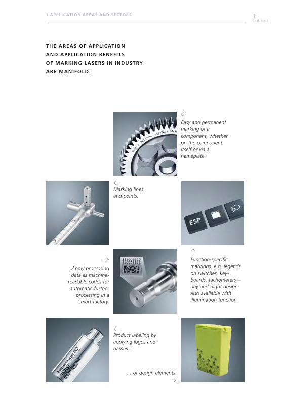
THE AREAS OF APPLICATION
AND APPLICATION BENEFITS
OF MARKING LASERS IN INDUSTRY
ARE MANIFOLD:
←
Easy and permanent marking of a component, whether on the component itself or via a nameplate.
←Marking lines and points.
→
Apply processing data as machine-
readable codes for automatic further
processing in a smart factory.
… or design elements.→
↑
Function-specific markings, e.g. legends on switches, key- boards, tachometers — day-and-night design also available with illumination function.
←Product labeling by applying logos and names ...
↑CONTENT
↑CONTENT
1 APPL IC AT ION AREAS AND SEC TORS
←
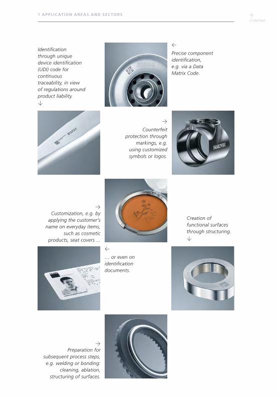
… or even on identification documents.
Identification through unique device identification (UDI) code for continuous traceability, in view of regulations around product liability. ↓
Creation of functional surfaces through structuring.↓
←
Precise component identification, e.g. via a Data Matrix Code.
→Preparation for
subsequent process steps, e.g. welding or bonding:
cleaning, ablation, structuring of surfaces.
→
Counterfeit protection through
markings, e.g. using customized symbols or logos.
→Customization, e.g. by
applying the customer’s name on everyday items,
such as cosmetic products, seat covers ...

↑CONTENT
↑CONTENT
↑CONTENT
1.1 TR ACEAB IL IT Y
1.1 TRACEABILITY
One of the reasons why it is important for industrial companies to mark their products
is that product liability laws and certifications have become stricter. In the case
of rejects and fault costs due to faulty supplier components, the costs can be legally
passed on to the party that caused them. This compels the industry to document
which elements were processed and to assign them to each order and component
accordingly. Manufacturers of security-related components in particular — such
as suppliers for the automotive and aerospace industries, for medical technology, and
also increasingly for sensor technology as well as electronics/electrical engineering —
are obliged to be able to report at any given time which of their individual components
were used within complete systems. Only a permanent, easily readable marking can
meet these requirements.
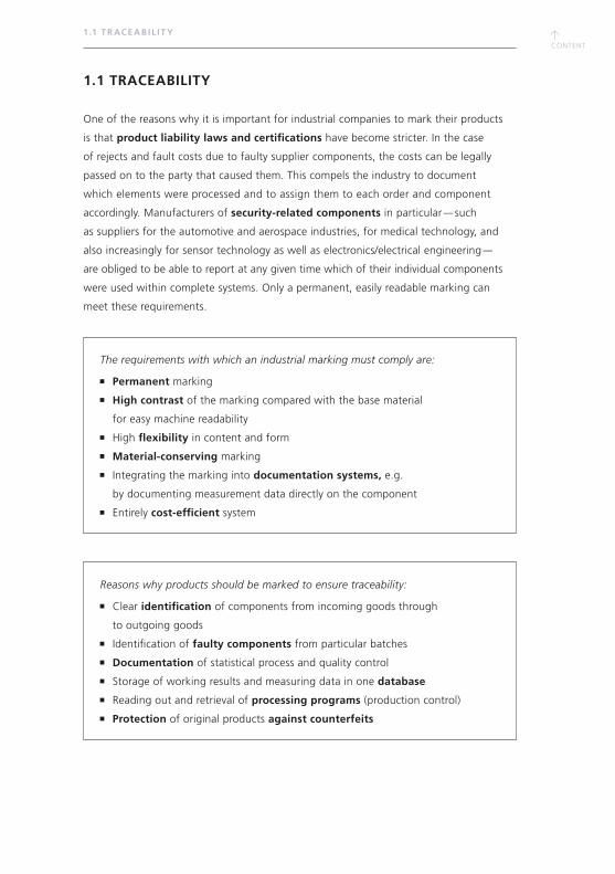
The requirements with which an industrial marking must comply are:
Permanent marking
High contrast of the marking compared with the base material
for easy machine readability
High flexibility in content and form
Material-conserving marking
Integrating the marking into documentation systems, e.g.
by documenting measurement data directly on the component
Entirely cost-efficient system
Reasons why products should be marked to ensure traceability:
Clear identification of components from incoming goods through
to outgoing goods
Identification of faulty components from particular batches
Documentation of statistical process and quality control
Storage of working results and measuring data in one database
Reading out and retrieval of processing programs (production control)
Protection of original products against counterfeits
↑CONTENT
1.1 TR ACEAB IL IT Y
WHAT TYPES OF MARKING ARE THERE?
Conventional markings on industrial components can be divided into design and text
markings as well as one-dimensional (only coded in one direction) and two-dimensional
(coded in x/y direction) types of coding. There are four principle types:
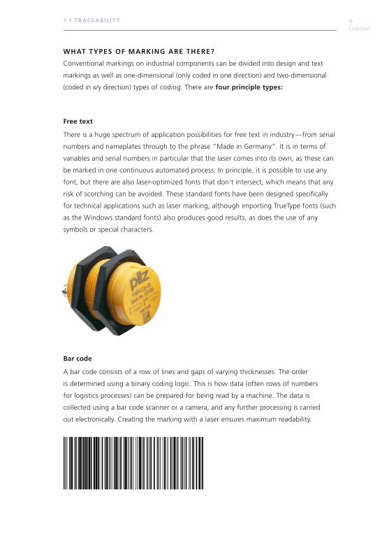
Free text
There is a huge spectrum of application possibilities for free text in industry — from serial
numbers and nameplates through to the phrase “Made in Germany”. It is in terms of
variables and serial numbers in particular that the laser comes into its own, as these can
be marked in one continuous automated process. In principle, it is possible to use any
font, but there are also laser-optimized fonts that don’t intersect, which means that any
risk of scorching can be avoided. These standard fonts have been designed specifically
for technical applications such as laser marking, although importing TrueType fonts (such
as the Windows standard fonts) also produces good results, as does the use of any
symbols or special characters.
Bar code
A bar code consists of a row of lines and gaps of varying thicknesses. The order
is determined using a binary coding logic. This is how data (often rows of numbers
for logistics processes) can be prepared for being read by a machine. The data is
collected using a bar code scanner or a camera, and any further processing is carried
out electronically. Creating the marking with a laser ensures maximum readability.

↑CONTENT
↑CONTENT
1.1 TR ACEAB IL IT Y
Data Matrix Code
Quiet zone Solid border Broken border Data storage
Data Matrix Code
The Data Matrix Code is probably the most well-known machine-readable 2D code.
It was developed by the US company International DATA Matrix in 1989, in order
to include more information into a code than had been possible with bar codes so far.
A Data Matrix Code consists of five elements: two continuous lines (solid border),
two broken lines (broken border), the actual data cells (data storage) and four light
fields that function as a quiet zone around the code. Most Data Matrix Codes
are square, although you also find rectangular ones.
Design elements and graphics
Graphics are often used for decorative purposes or for applying a company logo onto
a component, for example. The complexity of these types of graphics often varies quite
significantly. As a general rule, it is possible to import them in any conventional vector-
oriented graphic format (DXF/DWG, HPGL, IGES, etc.) and pixel format (BMP, JPG, etc.).
The software used to create marking content is equivalent to a fully fledged CAD
graphics program — for translating graphics content into laser programs.
↑CONTENT
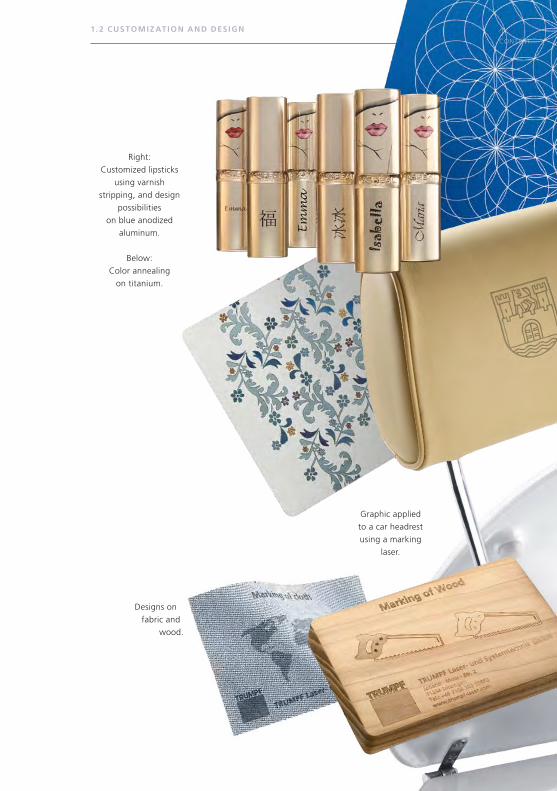
Right:
Customized lipsticks
using varnish
stripping, and design
possibilities
on blue anodized
aluminum.
Below:
Color annealing
on titanium.
Graphic applied
to a car headrest
using a marking
laser.
1. 2 CUSTOMIZ AT ION AND DES IGN
Designs on
fabric and
wood.
Vo
lksw
agen
AG
↑CONTENT
↑CONTENT
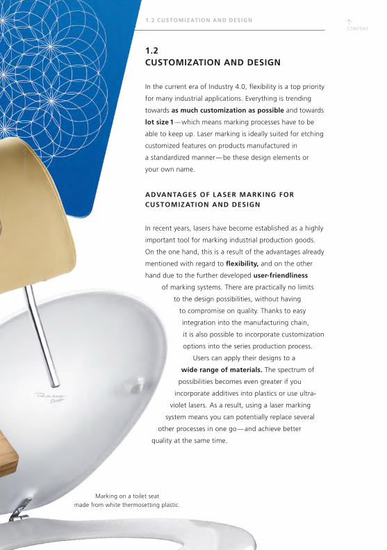
Marking on a toilet seat
made from white thermosetting plastic.
1. 2 CUSTOMIZ AT ION AND DES IGN
1.2 CUSTOMIZATION AND DESIGN
In the current era of Industry 4.0, flexibility is a top priority
for many industrial applications. Everything is trending
towards as much customization as possible and towards
lot size 1 — which means marking processes have to be
able to keep up. Laser marking is ideally suited for etching
customized features on products manufactured in
a standardized manner — be these design elements or
your own name.
ADVANTAGES OF LASER MARKING FOR CUSTOMIZATION AND DESIGN
In recent years, lasers have become established as a highly
important tool for marking industrial production goods.
On the one hand, this is a result of the advantages already
mentioned with regard to flexibility, and on the other
hand due to the further developed user- friendliness
of marking systems. There are practically no limits
to the design possibilities, without having
to compromise on quality. Thanks to easy
integration into the manufacturing chain,
it is also possible to incorporate customization
options into the series production process.
Users can apply their designs to a
wide range of materials. The spectrum of
possibilities becomes even greater if you
incorporate additives into plastics or use ultra-
violet lasers. As a result, using a laser marking
system means you can potentially replace several
other processes in one go — and achieve better
quality at the same time.
Vo
lksw
agen
AG
↑CONTENT
1. 3 PROCESS PREPAR ATION AND SURFACE TREATMENT
1.3 PROCESS PREPARATION AND SURFACE TREATMENT
Using short-pulse lasers for tasks other than classic marking applications has been the
norm for quite a long time. Thanks to their robustness and flexibility, they can also
be used for entirely different applications within the industry. The two most frequent
areas of application in terms of marking are the treatment of surfaces for preparing
subsequent joining processes and the functionalization of all types of surfaces.
WHY USE MARKING LASERS FOR PREPARING JOINING PROCESSES?
Functional layers — such as insulations or coatings for protecting surfaces — can be
challenging for joining processes like laser welding, soldering, and bonding. Although
these can sometimes be counteracted with corresponding parameterization, this has
a negative effect on the quality of the joining process. During the welding process, the
raw material of the functional layer combines with the molten metal and, thus, disturbs
the process. This can lead to spatters and inclusions. The consequences are sometimes
similar in the case of dirt layers. In the absence of an integrated laser process, it becomes
necessary to carry out complex pre- and postprocessing such as chemical cleaning
or sandblasting in order to guarantee quality.
In this situation, a marking laser serves as the ideal preparation tool. With short,
powerful pulses, it can remove protection, oxidization and functional layers, oil, grease,
and other contaminants from components just from the areas that need joining. This
method of localized cleaning makes the whole process very fast and ensures that
functional protection layers beyond the seam points remain intact. The welding process
runs more homogenously, faster, and with absolute repeatability. If a marking laser
is used in joining preparation, it can also apply a Data Matrix Code or serial number
to the component simultaneously. This takes care of both cleaning and traceability in
a single step.
At a glance — the advantages of using a marking laser as a complementary
tool in joining processes:
Easy integration into fully automatic production sequences, as all sequences
are carried out using computer control and because data
can be transferred very easily via interfaces.
No further preparatory work or reworking necessary
Option to mark large surfaces
Reach areas that are difficult to access
High processing speed
Environmentally friendly process
↑CONTENT
↑CONTENT
1. 3 PROCESS PREPAR ATION AND SURFACE TREATMENT
WHAT TYPES OF PROCESS PREPARATIONS AND SURFACE TREATMENTS ARE THERE?
Cleaning for welding preparation
With short and ultrashort pulses, marking lasers remove unwanted coatings from seam
points with utmost precision and without affecting the surface underneath. This leads to
both efficient processes and high-quality results in the subsequent welding stage.
The advantages of welding laser-cleaned components include:
Higher welding quality
Significantly fewer spatters during the welding process
Fewer pore inclusions during welding
Significantly smoother welding process
Local cleaning in a matter of seconds precisely at the seam points
High reproducibility and uniform cleaning result on the surface
Replaces time-consuming cleaning measures such as baths or sandblasting, and
can operate entirely without chemicals or other additional aids, residue-free
Removing grease and oil
In some instances, production-related grease and oil can collect on components.
It is advisable to remove these layers from the seam points to ensure a smooth and
spatter-free welding process and to guarantee high-quality results. The laser light
from the marking laser vaporizes the dirt, affecting the surface just very slightly.
Example
A typical area of application is the removal of oil residue from tubes. In just a single
pass, the marking laser can reliably vaporize the oil from all around the two ends
of the tube. The steam is transported away via a suction device and there is no need
for using compressed air.
↑CONTENT
(1) (2)
1. 3 PROCESS PREPAR ATION AND SURFACE TREATMENT
Removing corrosion and oxides
Corrosion and other forms of oxidation on the surface distort the visual appearance,
hamper any further processing (e.g. joining through bonding or welding), and restrict
the functionality. To combat these effects, the material can be vaporized with a laser
and sucked away. You simply adjust the laser power to the degree of corrosion and,
if necessary, pass over the area several times. A single pass removes corrosion of up to
100 μm thick. Using a scanner system, the removal rate is typically up to 30 cm2/s.
Cleaning molds
Using a marking laser to clean molds enables the extensive vaporizing of just the process
residue, and without wearing away the mold. Due to laser cleaning, the industry no
longer requires the use of cleaning methods that are either energy-intensive, problematic,
or cause wear, such as chemicals, dry ice, brushes, and sandblasting.
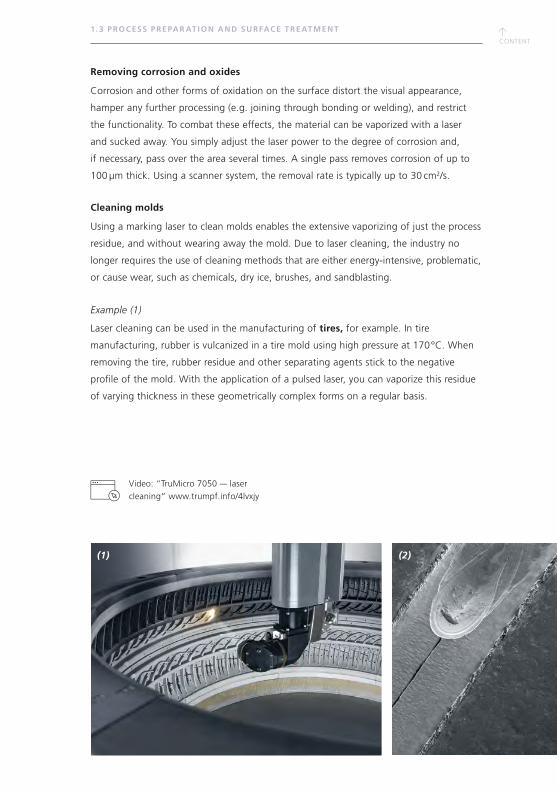
Example (1)
Laser cleaning can be used in the manufacturing of tires, for example. In tire
manufacturing, rubber is vulcanized in a tire mold using high pressure at 170 °C. When
removing the tire, rubber residue and other separating agents stick to the negative
profile of the mold. With the application of a pulsed laser, you can vaporize this residue
of varying thickness in these geometrically complex forms on a regular basis.
Video: “TruMicro 7050 — laser
cleaning” www.trumpf.info/4lvxjy
↑CONTENT
↑CONTENT
(3)
1. 3 PROCESS PREPAR ATION AND SURFACE TREATMENT
Decoating
In welding, galvanizing and applying nickel plating and anticorrosion layers can lead to
spatters and pore inclusions. To ensure that the process is smooth and to guarantee
high-quality results, it is advisable to remove these layers from the seam points. Following
the same principle, these types of layers can also be removed locally before soldering.
Example (2)
Deep-drawn, custom-cut steel sheet blanks, made up of different grades of material and
sheet thicknesses tailored blanks, are protected against corrosion with a 10 to 20 μm
thick layer of aluminum-silicon alloy (AlSi). During welding, the protection layer
causes spatters and porosity, which means that the connection is not necessarily secure.
For this reason, it nevitable to target and ablate the AlSi layer from just the seam points,
without affecting the base layer material underneath. Using short laser pulses makes it is
possible to ablate the layer with a processing speed of more than 5 cm2 /s.
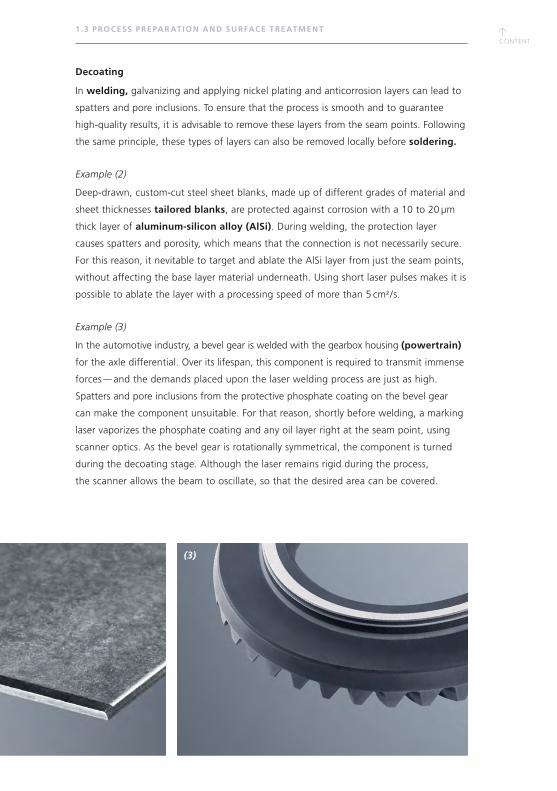
Example (3)
In the automotive industry, a bevel gear is welded with the gearbox housing (powertrain)
for the axle differential. Over its lifespan, this component is required to transmit immense
forces — and the demands placed upon the laser welding process are just as high.
Spatters and pore inclusions from the protective phosphate coating on the bevel gear
can make the component unsuitable. For that reason, shortly before welding, a marking
laser vaporizes the phosphate coating and any oil layer right at the seam point, using
scanner optics. As the bevel gear is rotationally symmetrical, the component is turned
during the decoating stage. Although the laser remains rigid during the process,
the scanner allows the beam to oscillate, so that the desired area can be covered.
↑CONTENT
(1)
1. 3 PROCESS PREPAR ATION AND SURFACE TREATMENT
(2)
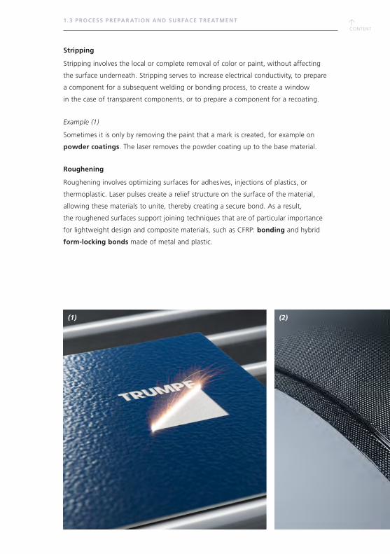
Stripping
Stripping involves the local or complete removal of color or paint, without affecting
the surface underneath. Stripping serves to increase electrical conductivity, to prepare
a component for a subsequent welding or bonding process, to create a window
in the case of transparent components, or to prepare a component for a recoating.
Example (1)
Sometimes it is only by removing the paint that a mark is created, for example on
powder coatings. The laser removes the powder coating up to the base material.
Roughening
Roughening involves optimizing surfaces for adhesives, injections of plastics, or
thermoplastic. Laser pulses create a relief structure on the surface of the material,
allowing these materials to unite, thereby creating a secure bond. As a result,
the roughened surfaces support joining techniques that are of particular importance
for lightweight design and composite materials, such as CFRP: bonding and hybrid
form-locking bonds made of metal and plastic.
↑CONTENT
↑CONTENT
(3)
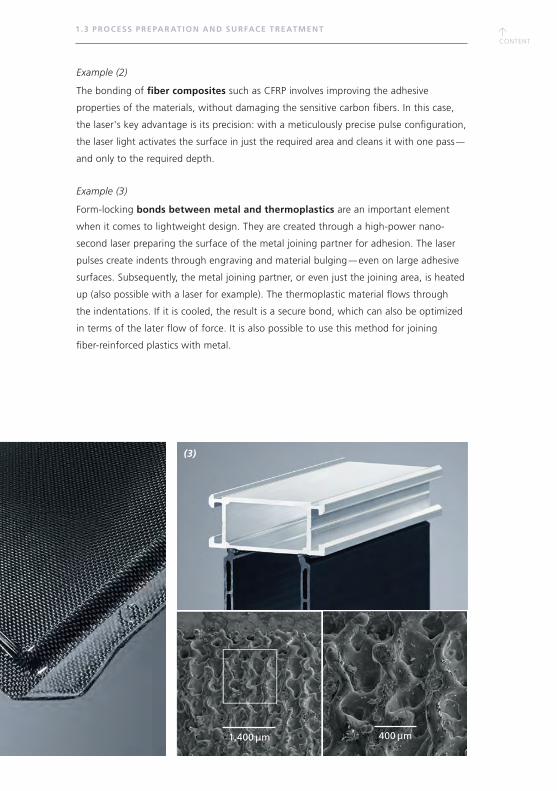
400 μm1,400 μm
1. 3 PROCESS PREPAR ATION AND SURFACE TREATMENT
Example (2)
The bonding of fiber composites such as CFRP involves improving the adhesive
properties of the materials, without damaging the sensitive carbon fibers. In this case,
the laser's key advantage is its precision: with a meticulously precise pulse configuration,
the laser light activates the surface in just the required area and cleans it with one pass —
and only to the required depth.
Example (3)
Form-locking bonds between metal and thermoplastics are an important element
when it comes to lightweight design. They are created through a high-power nano-
second laser preparing the surface of the metal joining partner for adhesion. The laser
pulses create indents through engraving and material bulging — even on large adhesive
surfaces. Subsequently, the metal joining partner, or even just the joining area, is heated
up (also possible with a laser for example). The thermoplastic material flows through
the indentations. If it is cooled, the result is a secure bond, which can also be optimized
in terms of the later flow of force. It is also possible to use this method for joining
fiber-reinforced plastics with metal.

↑CONTENT
(1)
1. 3 PROCESS PREPAR ATION AND SURFACE TREATMENT
CHANGING TRIBOLOGICAL PROPERTIES
With laser pulses, it is easy to engrave tiny structures into the
material, either to reduce friction (for reducing wear or lubricant
consumption) or to actively increase friction (for antirotation locking
or for a higher surface pressure). In this case, the laser-induced
structures are either cells, pockets, lines, or spirals.
Example (1)
Typical application areas of laser structuring for reducing friction
include the running surfaces of cylinders and the bearing seats
of shafts. In this case, grease lubricant cells are applied. It is also
possible to structure the inside of tubes, whereby the laser light
shines diagonally into the tube, structuring the surface. This is
facilitated by the step-by-step adjustment of the focus level via
internal defocusing.
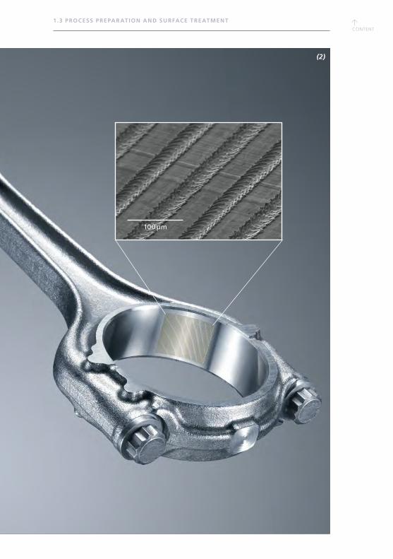
Example (2)
A typical application area of using laser structuring for increasing
friction is the bearing seat of a connecting rod in a drive.
The ridge structure increases the surface pressure of the bearing
shells at the large end of the connecting rod and decreases
the risk of slipping at high torques.
1.0 mm
↑CONTENT
↑CONTENT
(2)
1. 3 PROCESS PREPAR ATION AND SURFACE TREATMENT
100 μm

↑CONTENT
↑CONTENT
↑CONTENT
1. 4 MEDIC AL TECHNOLOGY
1.4 MEDICAL TECHNOLOGY
PARTICULAR CHALLENGES OF THIS SECTOR
Qualification
Quality management in the medical technology industry is strict. Amongst other things,
it also comprises validating any process that occurs within the production process.
One part of this validation stage involves qualifying any equipment used — known as
equipment qualification (EQ). Every piece of machinery, even if it was only used on
the periphery of the production process, is checked according to the strictest technical
standards. And of course, this is also the case for marking lasers. An equipment
qualification is usually divided into the following qualification stages:
Design qualification (DQ) outlines the requirements the machinery needs to comply
with and how this is to be achieved. This is often illustrated within specifications.
Installation qualification (IQ) verifies whether a machine complies with the
documented requirements, such as scope of functions, and whether it has been
installed correctly and all necessary accompanying documents are present.
Operation qualification (OQ) verifies whether the machine functions correctly
within the selected work environment. This stage includes checking that the system,
including all its individual settings, function according to the operational specifications.
Performance or process qualification (PQ) checks whether the machine carries
out the process within the process boundaries in a statistically safeguarded manner,
according to the specifications.
Manufacturers like TRUMPF can support customers with these qualifications, by
offering standardized packages for the IQ and OQ, for example. This gives the user
the advantage of receiving the necessary documentation straightaway.
Implementing the UDI requirements
Important markets like the US, China, and the EU place high demands on the trace-
ability of medical technology. The key word here is unique device identification (UDI).
Although the details of regulations vary, one thing is always clear: it is mandatory
for medical products to be marked with a code that contains any relevant information
(e.g. manufacturer, batch number, production date).
UDISoftware SolutionGLOBAL
UDI DATABASE (01)40565520000025(21)53256
MARKING
LASER
IMAGEPROCESSING
1
1
2
3
4
56
7
↑CONTENT
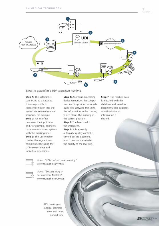
UDI marking on
surgical stainless
steel and laser
marked tube.
1. 4 MEDIC AL TECHNOLOGY
Steps to obtaining a UDI-compliant marking
Step 1: The software is
connected to databases.
It is also possible to
input information into the
system via external manual
scanners, for example.
Step 2: An interface
processes the input data
and, for example, connects
databases or control systems
with the marking laser.
Step 3: The UDI module
creates the regulations-
compliant code using the
UDI-relevant data and
individual extensions.
Step 4: An image-processing
device recognizes the compo-
nent and its position automat-
ically. The software transmits
the information to the control,
which places the marking in
the correct position.
Step 5: The laser marks
the workpiece.
Step 6: Subsequently,
automatic quality control is
carried out via a camera,
which reads and evaluates
the quality of the marking.
Step 7: The marked data
is matched with the
database and saved for
documentation purposes — with additional
information if
desired.
Video: “Success story of
our customer Miethke”
www.trumpf.info/0hyjw5
Video: “UDI-conform laser marking”
www.trumpf.info/tv7f8w
↑CONTENT
↑CONTENT
Traceability must be guaranteed
across the entire supply chain
and the entire lifespan of the
product. The code should be readable
for both machines and humans. It is essential
that the user has marking software that can
provide all of the necessary features. Therefore, it
must be able to master common standards such
as GS1, HIBC, or ISBT 128 and include the necessary
interfaces for importing all of the required data and,
if necessary, also be able to reexport these for any relevant
database.
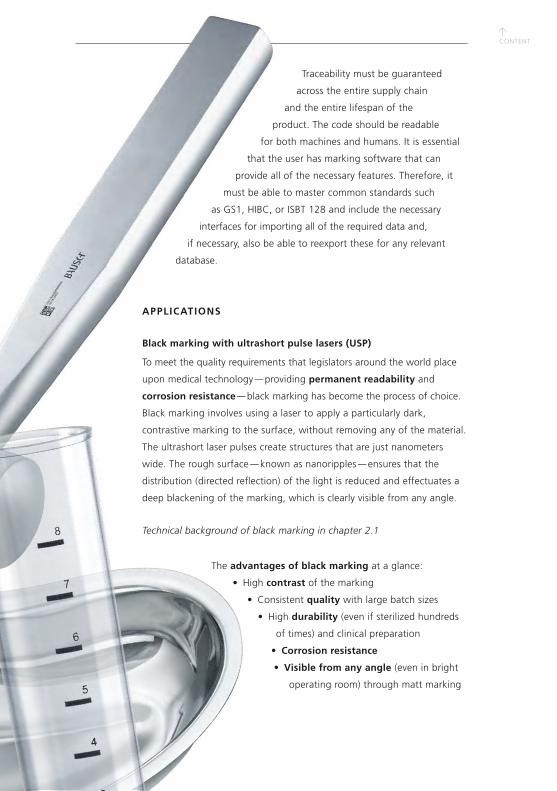
APPLICATIONS
Black marking with ultrashort pulse lasers (USP)
To meet the quality requirements that legislators around the world place
upon medical technology — providing permanent readability and
corrosion resistance — black marking has become the process of choice.
Black marking involves using a laser to apply a particularly dark,
contrastive marking to the surface, without removing any of the material.
The ultrashort laser pulses create structures that are just nanometers
wide. The rough surface — known as nanoripples — ensures that the
distribution (directed reflection) of the light is reduced and effectuates a
deep blackening of the marking, which is clearly visible from any angle.
Technical background of black marking in chapter 2.1
The advantages of black marking at a glance:
• High contrast of the marking
• Consistent quality with large batch sizes
• High durability (even if sterilized hundreds
of times) and clinical preparation
• Corrosion resistance
• Visible from any angle (even in bright
operating room) through matt marking

↑CONTENT
↑CONTENT
↑CONTENT
1.5 AUTOMOTIVE
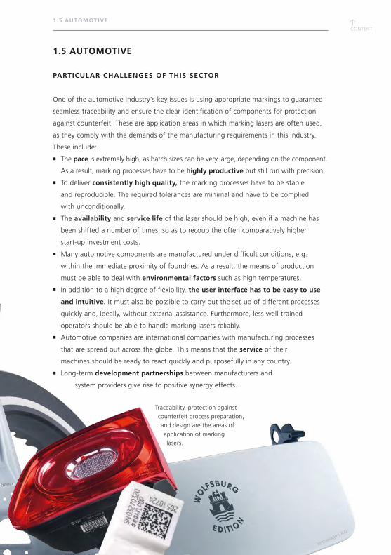
1.5 AUTOMOTIVE
PARTICULAR CHALLENGES OF THIS SECTOR
One of the automotive industry's key issues is using appropriate markings to guarantee
seamless traceability and ensure the clear identification of components for protection
against counterfeit. These are application areas in which marking lasers are often used,
as they comply with the demands of the manufacturing requirements in this industry.
These include:
The pace is extremely high, as batch sizes can be very large, depending on the component.
As a result, marking processes have to be highly productive but still run with precision.
To deliver consistently high quality, the marking processes have to be stable
and reproducible. The required tolerances are minimal and have to be complied
with unconditionally.
The availability and service life of the laser should be high, even if a machine has
been shifted a number of times, so as to recoup the often comparatively higher
start-up investment costs.
Many automotive components are manufactured under difficult conditions, e.g.
within the immediate proximity of foundries. As a result, the means of production
must be able to deal with environmental factors such as high temperatures.
In addition to a high degree of flexibility, the user interface has to be easy to use
and intuitive. It must also be possible to carry out the set-up of different processes
quickly and, ideally, without external assistance. Furthermore, less well-trained
operators should be able to handle marking lasers reliably.
Automotive companies are international companies with manufacturing processes
that are spread out across the globe. This means that the service of their
machines should be ready to react quickly and purposefully in any country.
Long-term development partnerships between manufacturers and
system providers give rise to positive synergy effects.
Traceability, protection against
counterfeit process preparation,
and design are the areas of
application of marking
lasers.
Volkswagen AG
↑CONTENT
1.5 AUTOMOTIVE
APPLICATIONS
Clear labeling for traceability and protection against counterfeit
The complex topic of traceability brings with it several application examples from
the automotive sector. The one encountered most frequently is surely the application
of Data Matrix Codes (DMC), although 1D bar codes are also still used. The
application of serial numbers, texts, logos, and certificate seals — intended for
component identification — also belong to the core applications in terms of
traceability.
The processes that are generally used for this are engraving
and — depending on the material — annealing or foaming, and color
changing. A typical example is light / white DMCs applied onto dark
plastic surfaces.
This is the method used for marking almost every component in a
vehicle. A well-known example of this is the vehicle identification
number (VIN), which has a clear identification purpose. In order to protect
against manipulation, the VIN is applied to several areas of a vehicle and is
always engraved to at least 300 µm conforming to standards, which ensures
that it is readable at all times. A challenge for the marking process is that engraved
areas are usually painted over afterwards, which is not allowed to impact negatively on
the marking quality. A great advantage of the laser here is its non-contact use, and
therefore freedom from wear, in comparison to mechanical processes such as needle
engraving. Using lasers, peripheral devices such as robots are not subject to strain
and their life is greatly extended. A further example for a similar type of
marking is shift stamping. Shift stamping involves engraving data about the
component and the shift onto any part that comes out of the press
plants, and is how an even larger quantity of data can find its way
into a vehicle. What all of these points have in common is
that handling the production data can be made more efficient
by implementing a holistic approach. In this regard, modern
production software and databases contribute a vast
number of useful functions, which makes handling
the data much easier.
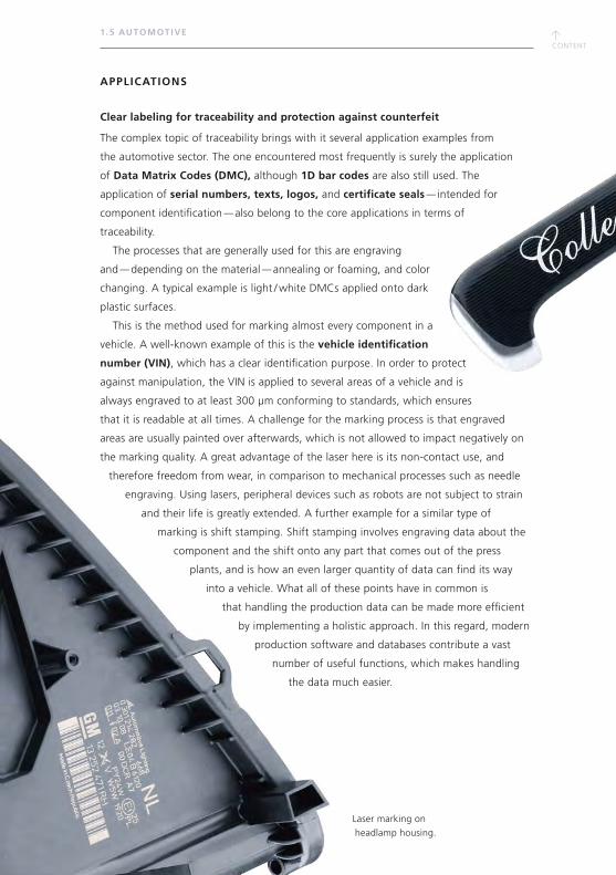
Laser marking on
headlamp housing.

↑CONTENT
↑CONTENT
1.5 AUTOMOTIVE
Smart Factory / production management
Due to the megatrend towards Industry
4.0, there is still a significant amount of
hidden potential in this area. The next logical
step would be an intelligent production process
that applies and reads out codes, in order to be able to control
the next production steps independently. So in this instance, it is not
the result of the marking process that is the focus, but rather the marking
is more of an aid in the production management. To be able to leverage all of the
opportunities afforded by intelligent production, numerous marking lasers need to
be integrated into the production chain, ideally with as little hassle as possible.
DESIGN AND CUSTOMIZATION
Above and beyond producing components that have a functional role, lasers also
play a huge part in automotive manufacturing when it comes to customization.
Some manufacturers give their customers the option of adding individual embellish-
ments to their car, for example by adding design elements to headrests, interior
doors, glove compartments, and other areas. This is usually achieved via color change.
In the premium sector in particular, a significant number of decorative markings are
applied to leather, wood, or fabrics. The huge challenge in this regard is having
to work with natural materials — grained wood, for example, is not the most even
material for applying markings. The solution is to use intricate parameterization,
so that the desired result can be achieved without damaging the material.
However, there are other design elements — also applied with a marking laser —
that serve a particular purpose. This includes the day-and-night designs of operating
elements, such as tachometers or switches.
In any case, regardless of whether the designs are a decorative addition or have an
optimization function, it is obligatory for the marking process to have stable process
parameters and tight tolerances.
Laser-marked trim and tachometer
with day-and-night design,
created by ablating several
layers of plastic.
↑CONTENT
1.5 AUTOMOTIVE
PROCESS PREPARATION AND SURFACE PROCESSING
Marking lasers can be used for many purposes
other than the actual marking process:
Cleaning and ablation for joining preparation
Structuring for bonding and
coating preparation
Creating tribological surfaces
Roughening for metal-plastic bonds
in lightweight design
Electromobility
Due to the increasing demand for electromobility,
manufacturers of electric motors are looking for more
productive processes that are easy to automate.
This is why short-pulsed lasers are being used more
and more in this area.
Coating preparation
When battery cells are filled, there is the risk that battery
acid and anode or cathode materials will leak and cause
contamination. A laser can clean and structure these
areas in just one process step. This allows any subsequent
coating processes — for electrical insulation for
example — to run smoothly.
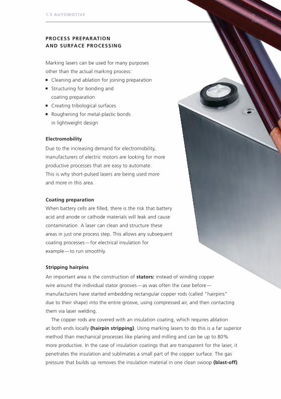
Stripping hairpins
An important area is the construction of stators: instead of winding copper
wire around the individual stator grooves — as was often the case before —
manufacturers have started embedding rectangular copper rods (called “hairpins”
due to their shape) into the entire groove, using compressed air, and then contacting
them via laser welding.
The copper rods are covered with an insulation coating, which requires ablation
at both ends locally (hairpin stripping). Using marking lasers to do this is a far superior
method than mechanical processes like planing and milling and can be up to 80%
more productive. In the case of insulation coatings that are transparent for the laser, it
penetrates the insulation and sublimates a small part of the copper surface. The gas
pressure that builds up removes the insulation material in one clean swoop (blast-off).
↑CONTENT
↑CONTENT
1.5 AUTOMOTIVE
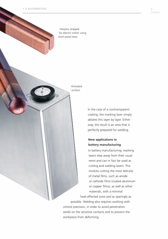
In the case of a nontransparent
coating, the marking laser simply
ablates this layer by layer. Either
way, the result is an area that is
perfectly prepared for welding.
New applications in
battery manufacturing
In battery manufacturing, marking
lasers step away from their usual
remit and can in fact be used as
cutting and welding lasers. This
involves cutting the most delicate
of metal films, such as anode
or cathode films (coated aluminum
or copper films), as well as other
materials, with a minimal
heat-affected zone and as sparingly as
possible. Welding also requires working with
utmost precision, in order to avoid penetration
welds on the sensitive contacts and to prevent the
workpiece from deforming.
Hairpins stripped
for electric motor using
short-pulse laser.
Activated
surface.

↑CONTENT

↑CONTENT
↑CONTENT
1.6 ELEC TRONICS
1.6 ELECTRONICS
PARTICULAR CHALLENGES OF THIS SECTOR
The particular demands in electronic applications make the case for the increased
use of marking lasers:
Electronic components are very sensitive. Process reliability, calculated energy
input, and adhering to tolerances are therefore imperative.
Electronic components are exposed to extreme conditions, which means
that markings need to be highly durable.
Electronic components consist of different materials, which requires the use of
different wavelengths, pulse durations, and power classes to ensure that the
most appropriate beam source can always be used for the right process.
Electronic components are often produced in large quantities. As a result, productivity
is extremely important and reliant on lasers that are both robust and have
a high uptime. They should also be as compact as possible and be equipped
with several interfaces for flexible fields of application.
APPLICATIONS
Marking
In the electronics sector, components are always marked with a Data Matrix Code,
which is the most frequent way in which marking lasers are used in this area. This involves
marking different types of materials that have different requirements, using a number
of different processes.
Marking lasers are also used in electronics to apply functional markings,
such as nameplates, CE marks, and batch numbers.
DESIGN AND CUSTOMIZATION
To date, apart from the manufacturer’s logo, design and customization have only played
a small part in the manufacturing of industrial electronic components. Functional
markings are more important when it comes to mass-manufactured products, such
as plugs, cables, and switches. Nonetheless, when there is a call for decorative elements,
marking lasers are also the tool of choice in the electronics industry. The recommended
product for this type of application is a UV laser, as it creates the marking using a
photochemical effect instead of just heat input. This method also enables markings
to be applied to flame-retardant materials.
↑CONTENT
1.6 ELEC TRONICS
PROCESS PREPARATION AND SURFACE TREATMENT
You can also use marking lasers in production steps in a manner
that you might never have guessed was possible, such as
preparing all manner of materials for joining. The laser’s task
in this case is the roughening, structuring, or cleaning
of surfaces, as joining partners prepared in this way adhere
together much better.
Marking lasers for joining
A similarly new application in the electronics sector with a vast
amount of potential is using nanosecond-pulsed marking lasers
for welding. The short pulses allow you to join sensitive and thin
components such as metal films more or less without any heat
input, and consequently without any distortion or deformation.
At the same time, using a marking laser for joining processes
permits a high degree of conductivity. In battery manufacturing,
this is exemplified by nano-pulsed marking lasers applying
several pulses one after the other to a weld point. At a
microlevel, it is possible to tell that this is no common weld
(no intermetallic phases), but rather the pulses generate
a type of mini hook-and-pile fastener (= form fit), enabling
the joining partners to join together mechanically, and
any contact resistance is kept to a minimum. In this way,
contacting different types of metals (e.g. aluminum
with copper) does not pose a problem, and metal films
and membranes can be joined without
becoming distorted.
Furthermore, it is also
possible to cut films
with a laser.
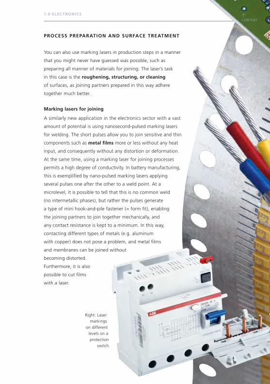
Right: Laser
markings
on different
levels on a
protection
switch.
↑CONTENT
↑CONTENT
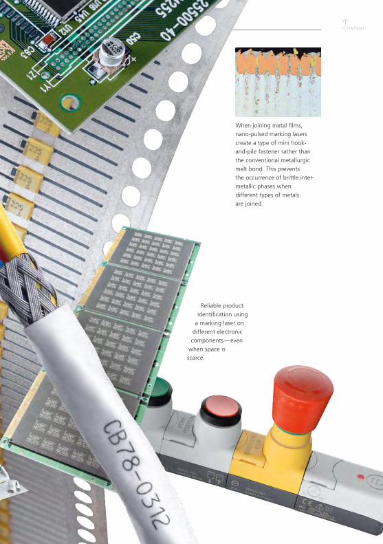
Reliable product
identification using
a marking laser on
different electronic
components — even
when space is
scarce.
When joining metal films,
nano-pulsed marking lasers
create a type of mini hook-
and-pile fastener rather than
the conventional metallurgic
melt bond. This prevents
the occurrence of brittle inter-
metallic phases when
different types of metals
are joined.

↑CONTENT
↑CONTENT
↑CONTENT
1.7 WHITE GOODS AND CONSUMER GOODS
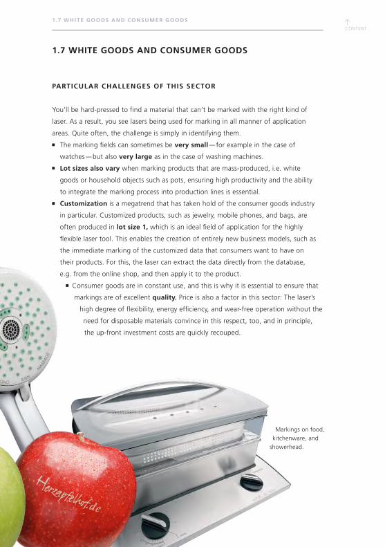
Markings on food,
kitchenware, and
showerhead.
1.7 WHITE GOODS AND CONSUMER GOODS
PARTICULAR CHALLENGES OF THIS SECTOR
You’ll be hard-pressed to find a material that can’t be marked with the right kind of
laser. As a result, you see lasers being used for marking in all manner of application
areas. Quite often, the challenge is simply in identifying them.
The marking fields can sometimes be very small — for example in the case of
watches — but also very large as in the case of washing machines.
Lot sizes also vary when marking products that are mass-produced, i.e. white
goods or household objects such as pots, ensuring high productivity and the ability
to integrate the marking process into production lines is essential.
Customization is a megatrend that has taken hold of the consumer goods industry
in particular. Customized products, such as jewelry, mobile phones, and bags, are
often produced in lot size 1, which is an ideal field of application for the highly
flexible laser tool. This enables the creation of entirely new business models, such as
the immediate marking of the customized data that consumers want to have on
their products. For this, the laser can extract the data directly from the database,
e.g. from the online shop, and then apply it to the product.
Consumer goods are in constant use, and this is why it is essential to ensure that
markings are of excellent quality. Price is also a factor in this sector: The laser’s
high degree of flexibility, energy efficiency, and wear-free operation without the
need for disposable materials convince in this respect, too, and in principle,
the up-front investment costs are quickly recouped.
↑CONTENT
1.7 WHITE GOODS AND CONSUMER GOODS
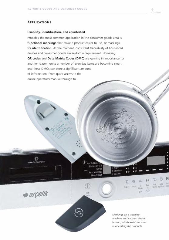
Markings on a washing machine and vacuum cleaner button, which assist the user in operating the products.
APPLICATIONS
Usability, identification, and counterfeit
Probably the most common application in the consumer goods area is
functional markings that make a product easier to use, or markings
for identification. At the moment, consistent traceability of household
devices and consumer goods are seldom a requirement. However,
QR codes and Data Matrix Codes (DMC) are gaining in importance for
another reason: quite a number of everyday items are becoming smart
and these DMCs can store a significant amount
of information. From quick access to the
online operator’s manual through to

↑CONTENT
↑CONTENT
1.7 WHITE GOODS AND CONSUMER GOODS
Razor housing,
tap and pan:
laser markings for
product designation,
conditions of use,
and protection
against counterfeit.
service-related notifications. Machine and smart-
phone-readable markings that are linked to
a database may be the solution. Markings in the
material or in particular locations that serve
as a form of protection against counterfeit are
also a category in their own right. Furthermore,
there is currently a trend in the food industry
for using lasers to apply a marking straight onto
the skin of fruits and vegetables — for example
an organic seal or other information. This is a way
of avoiding problematic packaging, and there is
an additional aesthetic benefit for the customer.
DESIGN AND CUSTOMIZATION
It is within the consumer goods industry that
design plays a particularly major role, as
it is a way for brands to stand out from
the competition and to offer their
customers aesthetic added value.
Marking lasers are becoming more and more
important in this regard, as they can be used
on almost any kind of material. Another trend is
the customization of goods — using your own
signature, for example — no matter whether on a
mobile phone, tablet, bag, or water bottle. This is
also an area of application for marking lasers, as lot
size 1 poses no challenge for these items. Finally,
event organizers at trade fairs, launches, parties, and
other special events can use marking lasers directly
on-site to impress their visitors and customers by
presenting them with a customized gift.

0123456789012345678901234567890123456789
0123456789012345678901234567890123456789
0123456789012345678901234567890123456789
0123456789012345678901234567890123456789
0123456789012345678901234567890123456789
0123456789012345678901234567890123456789
↑CONTENT
↑CONTENT
↑CONTENT
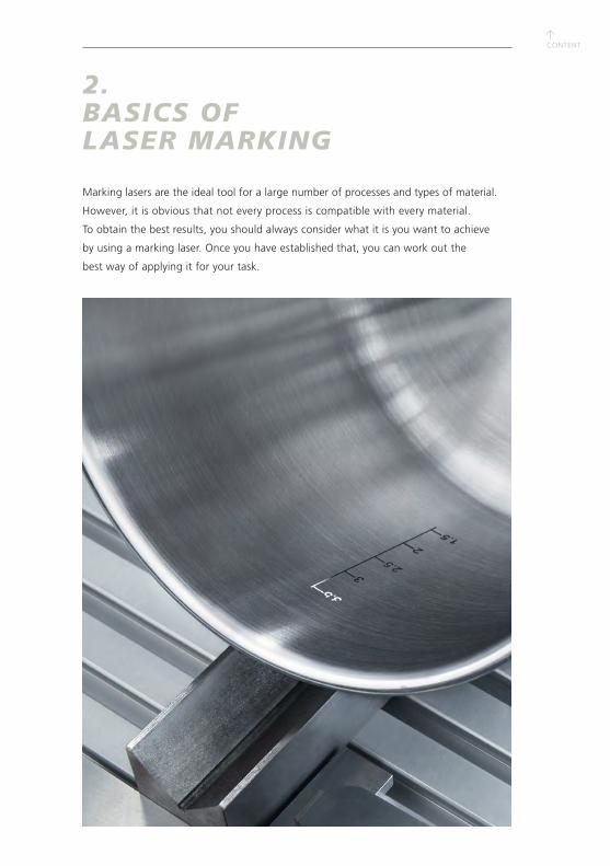
2. BASICS OF LASER MARKING
Marking lasers are the ideal tool for a large number of processes and types of material.
However, it is obvious that not every process is compatible with every material.
To obtain the best results, you should always consider what it is you want to achieve
by using a marking laser. Once you have established that, you can work out the
best way of applying it for your task.
↑CONTENT
2.1 METAL
Metals are characterized by their fixed lattice structure and free electrons, which is
what gives them an opaque appearance and enables them to conduct electrical
currents. When a laser beam hits the surface of a metal, a certain percentage of the
light is absorbed and there is an interaction with the electrons. Depending on the
intensity and exposure time of the laser light, the absorbed light increases the surface
temperature or causes the material to melt and evaporate.
DEEP ENGRAVING
In tool manufacturing and mold making or when marked components still require
reworking or additional painting, laser engravings need to be applied deeper into
the material — into the millimeter range. Typical applications include injection
molding tools as well as punching and embossing tools, for example. Deep
engraving has also proved useful for engraving vehicle identification numbers.
2 .1 METAL
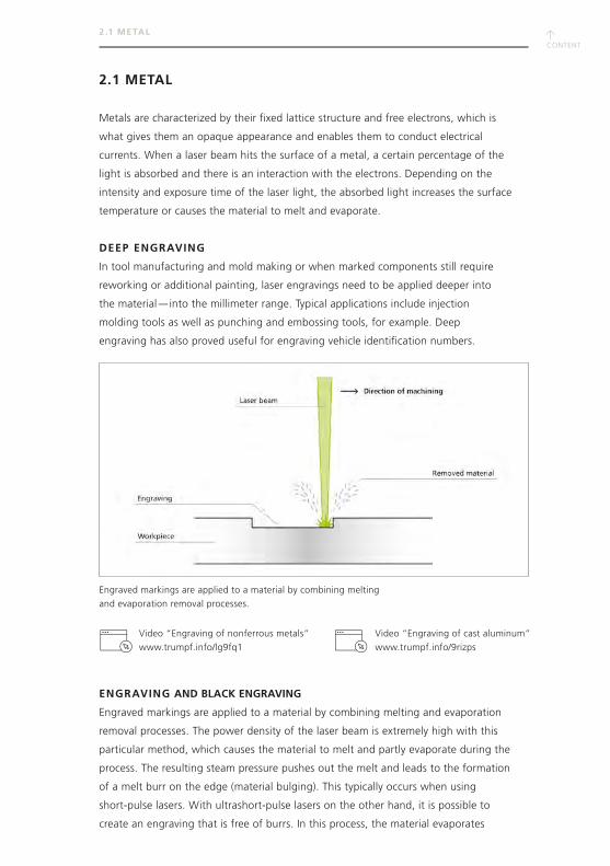
ENGRAVING AND BLACK ENGRAVING
Engraved markings are applied to a material by combining melting and evaporation
removal processes. The power density of the laser beam is extremely high with this
particular method, which causes the material to melt and partly evaporate during the
process. The resulting steam pressure pushes out the melt and leads to the formation
of a melt burr on the edge (material bulging). This typically occurs when using
short-pulse lasers. With ultrashort-pulse lasers on the other hand, it is possible to
create an engraving that is free of burrs. In this process, the material evaporates
Video “Engraving of nonferrous metals”
www.trumpf.info/lg9fq1
Video “Engraving of cast aluminum”
www.trumpf.info/9rizps
Engraved markings are applied to a material by combining melting
and evaporation removal processes.

↑CONTENT
↑CONTENT
2 .1 METAL
straightaway and creates a depression — the engraving, which is an extremely
wear-resistant type of marking. In the case of metals, the interaction of the molten
base material with the atmospheric oxygen leads to the formation of oxides which
are different in color. The surface, which is generally very rough, absorbs a lot of
light, and this is why the markings are usually black in appearance, or — depending
on the material — dark gray (aluminum) or dark brown (steel, brass, copper). Due to
their dark color, these markings are often referred to as “black engravings”.
Embossing punch with deep engraving. Black and white engraving for a Data Matrix Code.
Video “Engraving of galvanized steel”:
www.trumpf.info/efsro4
WHITE ENGRAVING
Applying a white engraving involves structuring the surface in a way that causes the
material to melt only slightly. The result is a smooth, highly reflective surface, which
in the case of certain materials such as galvanized steel has the appearance of a
white marking. Due to the low penetration depth, the coating remains intact and so
does its corrosion-resistance properties. This type of white engraving has a particular
advantage when applied to dark metals such as hardened steel as the high contrast
improves the readability of the marking. Furthermore, as the penetration depth only
extends into the micrometer range, it is also suitable for engraving component
surfaces that would be too greatly affected by a conventional engraving process.
ANNEALING AND BLACK MARKING WITH ULTRASHORT-PULSE LASERS
Annealing heats the material locally to just below its melting point. This generates
oxide layers on the surface of the workpiece which are associated with metallic
annealing colors. The contrast and the color depend on the thickness of the oxide
layer, and the quality of the surface remains completely unaffected. It is also the
preferred method whenever a precision fit is required or there is a need to avoid
material bulging. You can only anneal metals that change color when under the
influence of heat and oxygen, i.e. steels and titanium, but not aluminum or
nonferrous metals. It is also not possible to anneal carbide metals and achieve a dark
↑CONTENT
contrast. In this instance, it's only possible to create a light discoloration using a
nanosecond laser but a black marking with an ultrashort-pulse laser.
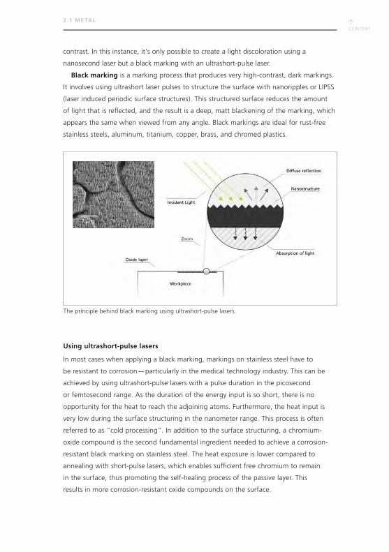
Black marking is a marking process that produces very high-contrast, dark markings.
It involves using ultrashort laser pulses to structure the surface with nanoripples or LIPSS
(laser induced periodic surface structures). This structured surface reduces the amount
of light that is reflected, and the result is a deep, matt blackening of the marking, which
appears the same when viewed from any angle. Black markings are ideal for rust-free
stainless steels, aluminum, titanium, copper, brass, and chromed plastics.
Using ultrashort-pulse lasers
In most cases when applying a black marking, markings on stainless steel have to
be resistant to corrosion — particularly in the medical technology industry. This can be
achieved by using ultrashort-pulse lasers with a pulse duration in the picosecond
or femtosecond range. As the duration of the energy input is so short, there is no
opportunity for the heat to reach the adjoining atoms. Furthermore, the heat input is
very low during the surface structuring in the nanometer range. This process is often
referred to as “cold processing”. In addition to the surface structuring, a chromium-
oxide compound is the second fundamental ingredient needed to achieve a corrosion-
resistant black marking on stainless steel. The heat exposure is lower compared to
annealing with short-pulse lasers, which enables sufficient free chromium to remain
in the surface, thus promoting the self-healing process of the passive layer. This
results in more corrosion-resistant oxide compounds on the surface.
7 μm
2 .1 METAL
The principle behind black marking using ultrashort-pulse lasers.
↑CONTENT
↑CONTENT
2 .1 METAL
Process qualification
To ensure that the readability and durability of black markings are long-lasting, even
when they come into contact with harsh cleaning agents and high temperatures
as in the case of medical technology devices, it is advisable to use targeted
passivation. In this case, an acid bath consisting of nitric acid or citric acid removes
highly reactive components from the surface (e.g., free iron ions) and encourages
the quick formation of a new and clean chromium oxide layer, for even better
corrosion resistance. The surface is cleaned simultaneously during this process, and
sulfurs are dissolved. The aim must always be to create a laser marking that can
withstand the passivation process and any continual cleaning processes. With the
precise selection of parameters, passivation may even no longer be needed. Using an
ultrashort-pulse laser is the best solution in this regard. However, a number of factors
need to be taken into consideration, which can be roughly summarized as follows:
The chemical composition of the material
The surface quality of the material
The purity of the surface
The potential passivation process
The following approach is recommended as the best way of evaluating these
considerations and factoring them in when designing your process:
1. Study of the parameters (potentially with different types of lasers)
2. Analysis of the corrosion resistance and passivation stability (no fading of the marking)
3. Definition of a process window
4. Correlation between the laser parameters, the structure of the oxide layer,
and corrosion resistance
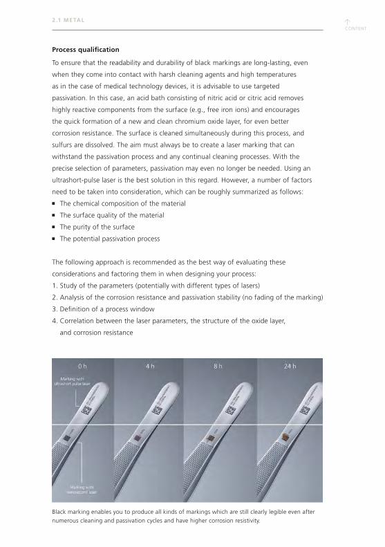
Black marking enables you to produce all kinds of markings which are still clearly legible even after
numerous cleaning and passivation cycles and have higher corrosion resistivity.
↑CONTENT
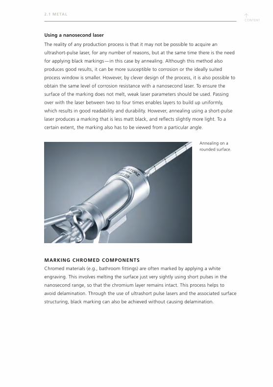
Using a nanosecond laser
The reality of any production process is that it may not be possible to acquire an
ultrashort-pulse laser, for any number of reasons, but at the same time there is the need
for applying black markings — in this case by annealing. Although this method also
produces good results, it can be more susceptible to corrosion or the ideally suited
process window is smaller. However, by clever design of the process, it is also possible to
obtain the same level of corrosion resistance with a nanosecond laser. To ensure the
surface of the marking does not melt, weak laser parameters should be used. Passing
over with the laser between two to four times enables layers to build up uniformly,
which results in good readability and durability. However, annealing using a short-pulse
laser produces a marking that is less matt black, and reflects slightly more light. To a
certain extent, the marking also has to be viewed from a particular angle.
MARKING CHROMED COMPONENTS
Chromed materials (e.g., bathroom fittings) are often marked by applying a white
engraving. This involves melting the surface just very sightly using short pulses in the
nanosecond range, so that the chromium layer remains intact. This process helps to
avoid delamination. Through the use of ultrashort pulse lasers and the associated surface
structuring, black marking can also be achieved without causing delamination.
2 .1 METAL
Annealing on a
rounded surface.
↑CONTENT
↑CONTENT
ANODIZED COATINGS
Markings on anodized or galvanized materials are often applied by removing the
surface layer until you reach the base material. As anodized coatings are usually
dark in color, the final marking is light in contrast and easy to identify. In the case of
transparent or naturally anodized aluminum, it is also possible to penetrate the
transparent anodized layer and to apply the marking on the boundary layer without
damaging the material. This involves marking beneath the actual surface, so the
result is fully corrosion-resistant and also very high in contrast (black).
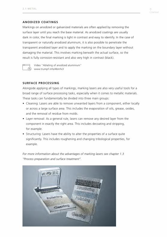
SURFACE PROCESSING
Alongside applying all types of markings, marking lasers are also very useful tools for a
broad range of surface processing tasks, especially when it comes to metallic materials.
These tasks can fundamentally be divided into three main groups:
• Cleaning: Lasers are able to remove unwanted layers from a component, either locally
or across a large surface area. This includes the evaporation of oils, grease, oxides,
and the removal of residue from molds.
• Layer removal: As a general rule, lasers can remove any desired layer from the
component in exactly the right area. This includes decoating and stripping,
for example.
• Structuring: Lasers have the ability to alter the properties of a surface quite
significantly. This includes roughening and changing tribological properties, for
example.
For more information about the advantages of marking lasers see chapter 1.3
“Process preparation and surface treatment”.
2 .1 METAL
Video “Ablating of anodized aluminium”
www.trumpf.info/4bmfx3
↑CONTENT
2.2 PLASTICS
Plastics are synthetically created, organic materials. They are made up of hydrocarbon
compounds, which are formed into macromolecules. The only exception are organic
silicon compounds. Plastics are subdivided into three groups according to their inner
structure.
THERMOPLASTICS
Thermoplastics consist of filamentary macromolecules that intertwine and do not have
any crosslinks. At room temperature, thermoplastics are hard. However, when exposed
to increasing temperatures, they first become soft, then take on a liquid form, and then
disintegrate. In a soft or liquid state, they can be molded into almost any desired shape.
THERMOSETTING PLASTICS
Thermosetting plastics comprise of macromolecules that are closely interlinked at a
number of different crosslinking points. When they are heated, their mechanical
properties change only very slightly, as the crosslinks do not allow the macromolecules to
shift. If thermosetting plastics are heated to a very high temperature, they disintegrate
without initially becoming soft or fluid.
ELASTOMERS
Elastomers are plastics with rubber-elastic properties. They are built up of macromol-
ecules that are interlinked in a wide mesh structure. When subjected to heat, the
rubber-elastic properties change only slightly. If heated too much, elastomers also
disintegrate without first taking on a liquid state.
ADDITIVES
The base structures of plastics contain all kinds of different additives:
Fillers such as carbon black, quartz, and glass fibers
Processing aids such as lubricants
Additives such as chemical stabilizers or flame retardants
Soluble organic dyes
Chromophoric pigments
The combination of the additives influences how well a laser is able to mark a plastic.
Quite often, a slight change to an additive — for example a dye — can bring about a
considerable improvement in the marking properties. The crucial factor is that it must
always be possible for the material to absorb the wavelength of the laser.
2 . 2 PL AST ICS
↑CONTENT
↑CONTENT
MARKING LASER PROCESS
There are four different ways in which lasers can be used for marking plastics:
Color change of the surface (discoloration, bleaching, or carbonizing)
Engraving (removing material from the matrix material on the surface)
Surface change (foaming or melting)
Ablation of layers (e.g., paint)
ABSORPTION CHARACTERISTICS
The manner in which the laser beam interacts with the material can vary greatly. The
important thing when using a marking laser is that the material has sufficient capacity
to absorb the light. In the case of metals, most of the light is reflected. With plastics,
on the other hand, light absorption and the transmission or diffuse reflection of the
light are of greater significance. As plastics do not have much heat conductivity, the
energy loss during the marking process is very low. This enables you to apply markings
to plastics with significantly greater speed than in the case of metals.
The macromolecular basic structure of plastics — the matrix — generally absorbs light
within the ultraviolet and far infrared ranges of the spectrum. The different additives
absorb light at different ranges along the wavelength spectrum. Additives such as
carbon black absorb light in the near infrared range, which means they can also absorb
the wavelength of a solid-state laser. Dyes, on the other hand, absorb light in the visible
light range. As you can acquire lasers with different wavelengths, you can select the
ideal wavelength for the relevant material.
ADDITIVES
It is advisable to mix certain industrial plastics with laser-sensitive additives to meet
the requirements of good readability and high-quality marking. These additives
change the chemical composition of the plastics, thus adapting the material to the
particular application or product. The specific optical, thermal, physical, and electrical
characteristics of the plastics remain largely intact. Laser additives are usually
color-neutral. They can consist, for example, of passive pigments — in the form of
tiny mica platelets — which are mixed into the material in a very low concentration.
This improves the absorption of the laser radiation of a certain wavelength (usually
designed for 1,064 nm) in the material. In addition to the color contrast, it is also
possible to increase the processing speed through laser additives.
WAVELENGTHS
The role of the laser wavelength is always a crucial factor in the marking of synthetic
materials, especially if you want to select the most suitable laser for a specific
application. Absorption is heavily influenced by the types of additives that are
incorporated. You have a greater choice of plastics that lend themselves well to being
2 . 2 PL AST ICS
↑CONTENT
2 . 2 PL AST ICS
marked if you use a solid-state laser with a double frequency (532 nm, green) or triple
frequency (355 nm, UV), which also often produces better results than the standard
systems with a wavelength of 1,064 or 1,030 nm.
WHAT TYPE OF PLASTICS CAN BE MARKED USING CONVENTIONAL
SHORT-PULSE LASERS WITH A WAVELENGTH OF 1,064 NM?
Good marking results
without additives
Average marking results without additives, but good marking results with laser addi-
tives (color-dependent characteristics)
Not possible to mark, or only with special additives
ABSPC
PPSUPBT
PBTPStyrene (SAN)
PEEKUREA
PSPI
PETPPOMPPSASA
PESPEIPESPEPA
PVCTPE
PolyesterPU
Polyolefine (PEHD, PP)
PMMAPTFE
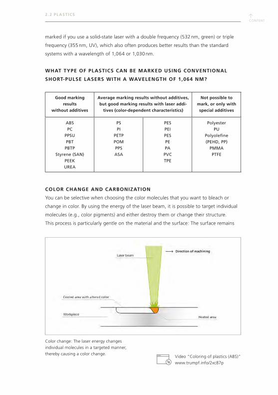
COLOR CHANGE AND CARBONIZATION
You can be selective when choosing the color molecules that you want to bleach or
change in color. By using the energy of the laser beam, it is possible to target individual
molecules (e.g., color pigments) and either destroy them or change their structure.
This process is particularly gentle on the material and the surface: The surface remains
Color change: The laser energy changes
individual molecules in a targeted manner,
thereby causing a color change.Video “Coloring of plastics (ABS)”
www.trumpf.info/2xc87p
↑CONTENT
↑CONTENT
2 . 2 PL AST ICS
largely intact and smooth. If material and wavelength are well matched (e.g., by using
laser-sensitive active pigments), it is possible to achieve the same effect even in the case
of 1,064 nm. However, with this wavelength, the plastic usually already carbonizes in
the matrix. During the carbonization process, the carbon-based plastic practically burns
(i.e. carbonizes) on the surface. Carbonization is often used for marking light-colored
plastics with a penetration depth of up to 200 μm. In the case of transparent materials
(e.g., polycarbonate), there is partly a type of shadow effect in the depression, depending
on the laser light transparency and the penetration depth of the laser radiation.
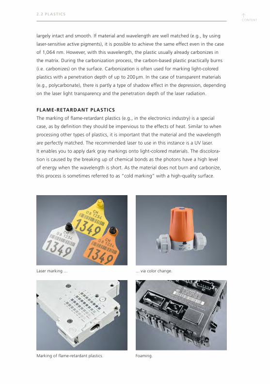
FLAME-RETARDANT PLASTICS
The marking of flame-retardant plastics (e.g., in the electronics industry) is a special
case, as by definition they should be impervious to the effects of heat. Similar to when
processing other types of plastics, it is important that the material and the wavelength
are perfectly matched. The recommended laser to use in this instance is a UV laser.
It enables you to apply dark gray markings onto light-colored materials. The discolora-
tion is caused by the breaking up of chemical bonds as the photons have a high level
of energy when the wavelength is short. As the material does not burn and carbonize,
this process is sometimes referred to as “cold marking” with a high-quality surface.
Foaming.Marking of flame-retardant plastics.
Laser marking ... ... via color change.
↑CONTENT
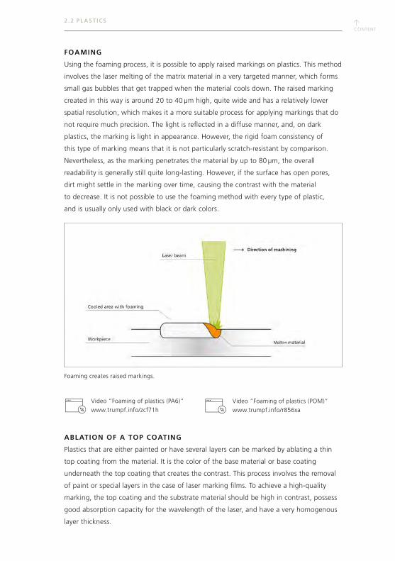
FOAMING
Using the foaming process, it is possible to apply raised markings on plastics. This method
involves the laser melting of the matrix material in a very targeted manner, which forms
small gas bubbles that get trapped when the material cools down. The raised marking
created in this way is around 20 to 40 μm high, quite wide and has a relatively lower
spatial resolution, which makes it a more suitable process for applying markings that do
not require much precision. The light is reflected in a diffuse manner, and, on dark
plastics, the marking is light in appearance. However, the rigid foam consistency of
this type of marking means that it is not particularly scratch-resistant by comparison.
Nevertheless, as the marking penetrates the material by up to 80 μm, the overall
readability is generally still quite long-lasting. However, if the surface has open pores,
dirt might settle in the marking over time, causing the contrast with the material
to decrease. It is not possible to use the foaming method with every type of plastic,
and is usually only used with black or dark colors.
ABLATION OF A TOP COATING
Plastics that are either painted or have several layers can be marked by ablating a thin
top coating from the material. It is the color of the base material or base coating
underneath the top coating that creates the contrast. This process involves the removal
of paint or special layers in the case of laser marking films. To achieve a high-quality
marking, the top coating and the substrate material should be high in contrast, possess
good absorption capacity for the wavelength of the laser, and have a very homogenous
layer thickness.
2 . 2 PL AST ICS
Foaming creates raised markings.
Video “Foaming of plastics (PA6)”
www.trumpf.info/zcf71hVideo “Foaming of plastics (POM)”
www.trumpf.info/r856xa
↑CONTENT
↑CONTENT
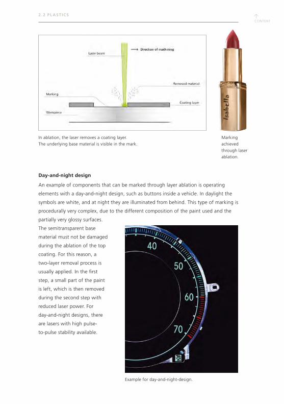
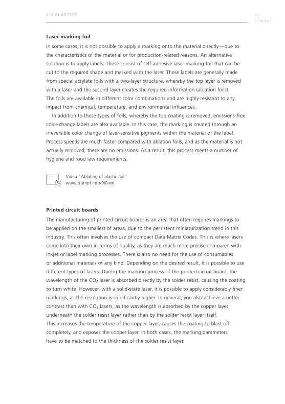
Day-and-night design
An example of components that can be marked through layer ablation is operating
elements with a day-and-night design, such as buttons inside a vehicle. In daylight the
symbols are white, and at night they are illuminated from behind. This type of marking is
procedurally very complex, due to the different composition of the paint used and the
partially very glossy surfaces.
The semitransparent base
material must not be damaged
during the ablation of the top
coating. For this reason, a
two-layer removal process is
usually applied. In the first
step, a small part of the paint
is left, which is then removed
during the second step with
reduced laser power. For
day-and-night designs, there
are lasers with high pulse-
to-pulse stability available.
Marking
achieved
through laser
ablation.
2 . 2 PL AST ICS
Example for day-and-night-design.
In ablation, the laser removes a coating layer.
The underlying base material is visible in the mark.
↑CONTENT
2 . 2 PL AST ICS
Laser marking foil
In some cases, it is not possible to apply a marking onto the material directly — due to
the characteristics of the material or for production-related reasons. An alternative
solution is to apply labels. These consist of self-adhesive laser marking foil that can be
cut to the required shape and marked with the laser. These labels are generally made
from special acrylate foils with a two-layer structure, whereby the top layer is removed
with a laser and the second layer creates the required information (ablation foils).
The foils are available in different color combinations and are highly resistant to any
impact from chemical, temperature, and environmental influences.
In addition to these types of foils, whereby the top coating is removed, emissions-free
color-change labels are also available. In this case, the marking is created through an
irreversible color change of laser-sensitive pigments within the material of the label.
Process speeds are much faster compared with ablation foils, and as the material is not
actually removed, there are no emissions. As a result, this process meets a number of
hygiene and food law requirements.
Printed circuit boards
The manufacturing of printed circuit boards is an area that often requires markings to
be applied on the smallest of areas, due to the persistent miniaturization trend in this
industry. This often involves the use of compact Data Matrix Codes. This is where lasers
come into their own in terms of quality, as they are much more precise compared with
inkjet or label marking processes. There is also no need for the use of consumables
or additional materials of any kind. Depending on the desired result, it is possible to use
different types of lasers. During the marking process of the printed circuit board, the
wavelength of the CO2 laser is absorbed directly by the solder resist, causing the coating
to turn white. However, with a solid-state laser, it is possible to apply considerably finer
markings, as the resolution is significantly higher. In general, you also achieve a better
contrast than with CO2 lasers, as the wavelength is absorbed by the copper layer
underneath the solder resist layer rather than by the solder resist layer itself.
This increases the temperature of the copper layer, causes the coating to blast off
completely, and exposes the copper layer. In both cases, the marking parameters
have to be matched to the thickness of the solder resist layer.
Video “Ablating of plastic foil”
www.trumpf.info/9i0axd
↑CONTENT
↑CONTENT
2.3 OTHER NONMETALS
In addition to metals and plastics, ceramics and sintered mixed materials can also be
marked with the laser. The primary advantages of this process are revealed where
mechanical processes reach their limits due to the high material hardness. Uniform
marking on natural materials such as wood, leather, and fruits is often difficult
because of the sometimes variable absorption behavior.
The processes vary as much as the materials. Ceramics and other brittle-hard materials
such as semiconductors are engraved, ablated, and drilled. Glass can also receive
subsurface marking. Fiber composite materials are ablated and drilled. Color changes
predominate in natural materials, and in isolated cases (e.g. leather), even perforations
are possible.
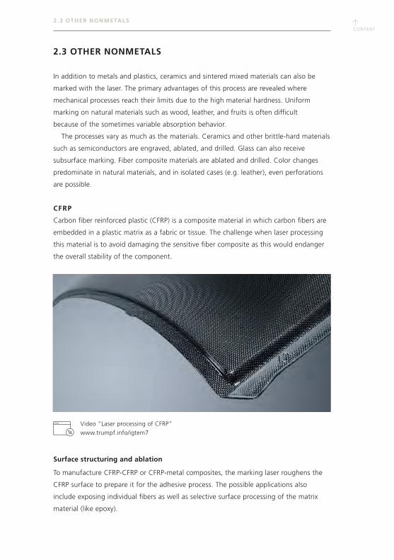
CFRP
Carbon fiber reinforced plastic (CFRP) is a composite material in which carbon fibers are
embedded in a plastic matrix as a fabric or tissue. The challenge when laser processing
this material is to avoid damaging the sensitive fiber composite as this would endanger
the overall stability of the component.
Surface structuring and ablation
To manufacture CFRP-CFRP or CFRP-metal composites, the marking laser roughens the
CFRP surface to prepare it for the adhesive process. The possible applications also
include exposing individual fibers as well as selective surface processing of the matrix
material (like epoxy).
2 . 3 OTHER NONMETALS
Video “Laser processing of CFRP”
www.trumpf.info/igtem7
↑CONTENT
Infrared laser light makes it possible to realize attractive ablation rates with acceptable
quality. However, there is a significant heat-affected zone, because the fiber material
absorbs the infrared laser light almost completely. At the green wavelength, the quality
is significantly better, but the ablation rates are somewhat lower. The best quality is
produced by ultraviolet lasers.
Marking
Lettering, codes, or logos can be marked in CFRP using color change or engraving.
The same conditions apply to engraving as to ablation. A color change is usually
produced in the plastic matrix. The selection of parameters depends on the matrix
material. Generally, the UV laser achieves good results, but the contrast usually
stays somewhat low.
GLASS
Because of its transparency and its amorphous surface structure, glass is a difficult
material for laser marking. Infrared laser light is as good as not absorbed. There is only
an interaction when the laser beam is extremely focused on the workpiece or the peak
pulse power is very high, as in the case of the ultrashort-pulse laser. Processing with
ultrashort-pulse lasers is also possible with IR lasers at a wavelength of 1,030 nm.
That is due to the interaction between the laser radiation and the material, which is very
different from processing with long pulses. In the case of glass, free carriers are first
created by multiphoton absorption which then continues to absorb laser radiation
and creates many new free electrons caused by impacts like an avalanche (also called
avalanche ionization). These processes are very fast in comparison to heat conduction
processes. Frequency-tripled lasers with a wavelength of 355 nm are used in short-
pulse lasers. The glass also absorbs the laser light from this UV laser very well because
of the high-energy photons.
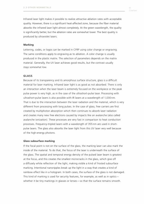
Glass subsurface marking
If the focal point is not on the surface of the glass, the marking laser can also mark the
inside of the material. To do that, the focus of the laser is underneath the surface of
the glass. The spatial and temporal energy density of the pulsed laser beam is greatest
at the focus, and this creates the smallest microcracks in the glass, which give off
a diffusely white reflection of the light, making visible a kind of frosted subsurface
marking. Intentional nanoripples break up the light in a way that creates a kind of
rainbow effect like in a hologram. In both cases, the surface of the glass is not damaged.
This kind of marking is used for security features, for example, as well as in optics —
whether it be tiny markings in glasses or lenses — so that the surface remains smooth.
2 . 3 OTHER NONMETALS
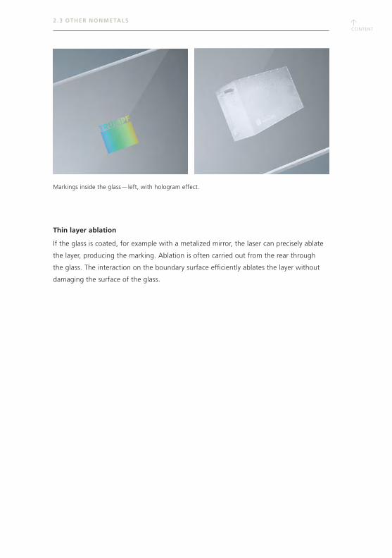
↑CONTENT
↑CONTENT
2 . 3 OTHER NONMETALS
Thin layer ablation
If the glass is coated, for example with a metalized mirror, the laser can precisely ablate
the layer, producing the marking. Ablation is often carried out from the rear through
the glass. The interaction on the boundary surface efficiently ablates the layer without
damaging the surface of the glass.
Markings inside the glass — left, with hologram effect.
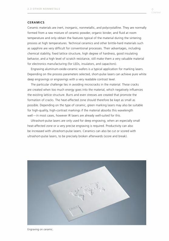
↑CONTENT
2 . 3 OTHER NONMETALS
CERAMICS
Ceramic materials are inert, inorganic, nonmetallic, and polycrystalline. They are normally
formed from a raw mixture of ceramic powder, organic binder, and fluid at room
temperature and only obtain the features typical of the material during the sintering
process at high temperatures. Technical ceramics and other brittle-hard materials such
as sapphire are very difficult for conventional processes. Their advantages, including
chemical stability, fixed lattice structure, high degree of hardness, good insulating
behavior, and a high level of scratch resistance, still make them a very valuable material
for electronics manufacturing (for LEDs, insulators, and capacitors).
Engraving aluminum-oxide-ceramic wafers is a typical application for marking lasers.
Depending on the process parameters selected, short-pulse lasers can achieve pure white
deep engravings or engravings with a very readable contrast level.
The particular challenge lies in avoiding microcracks in the material. These cracks
are created when too much energy goes into the material, which negatively influences
the existing lattice structure. Burrs and even stresses are created that promote the
formation of cracks. The heat-affected zone should therefore be kept as small as
possible. Depending on the type of ceramic, green marking lasers may also be suitable
for high-quality, high-contrast markings if the material absorbs this wavelength
well — in most cases, however IR lasers are already well-suited for this.
Ultrashort-pulse lasers are only used for deep engraving, when an especially small
heat-affected zone or a very precise engraving is required. Productivity can also
be increased with ultrashort-pulse lasers. Ceramics can also be cut or scored with
ultrashort-pulse lasers, to be precisely broken afterwards (score and break).
Engraving on ceramic.
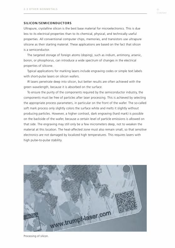
↑CONTENT
↑CONTENT
2 . 3 OTHER NONMETALS
SILICON/SEMICONDUCTORS
Ultrapure, crystalline silicon is the best base material for microelectronics. This is due
less to its electrical properties than to its chemical, physical, and technically useful
properties. All conventional computer chips, memories, and transistors use ultrapure
silicone as their starting material. These applications are based on the fact that silicon
is a semiconductor.
The targeted storage of foreign atoms (doping), such as indium, antimony, arsenic,
boron, or phosphorus, can introduce a wide spectrum of changes in the electrical
properties of silicone.
Typical applications for marking lasers include engraving codes or simple text labels
with short-pulse lasers on silicon wafers.
IR lasers penetrate deep into silicon, but better results are often achieved with the
green wavelength, because it is absorbed on the surface.
To ensure the purity of the components required by the semiconductor industry, the
components must be free of particles after laser processing. This is achieved by selecting
the appropriate process parameters, in particular on the front of the wafer. The so-called
soft mark process only slightly colors the surface white and melts it slightly without
producing particles. However, a higher contrast, dark engraving (hard mark) is possible
on the backside of the wafer, because a certain level of particle emissions is allowed on
that side. The engraving may still only be a few micrometers deep, not to weaken the
material at this location. The heat-affected zone must also remain small, so that sensitive
electronics are not damaged by localized high temperatures. This requires lasers with
high pulse-to-pulse stability.
Processing of silicon.
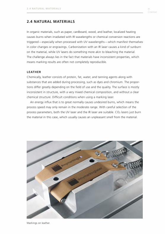
↑CONTENT
2 . 4 NATUR AL MATER IALS
2.4 NATURAL MATERIALS
In organic materials, such as paper, cardboard, wood, and leather, localized heating
causes burns when irradiated with IR wavelengths or chemical conversion reactions are
triggered — especially when processed with UV wavelengths — which manifest themselves
in color changes or engravings. Carbonization with an IR laser causes a kind of sunburn
on the material, while UV lasers do something more akin to bleaching the material.
The challenge always lies in the fact that materials have inconsistent properties, which
means marking results are often not completely reproducible.
LEATHER
Chemically, leather consists of protein, fat, water, and tanning agents along with
substances that are added during processing, such as dyes and chromium. The propor-
tions differ greatly depending on the field of use and the quality. The surface is mostly
inconsistent in structure, with a very mixed chemical composition, and without a clear
chemical structure. Difficult conditions when using a marking laser.
An energy influx that is to great normally causes undesired burns, which means the
process speed may only remain in the moderate range. With careful selection of the
process parameters, both the UV laser and the IR laser are suitable. CO2 lasers just burn
the material in this case, which usually causes an unpleasant smell from the material.
Markings on leather.
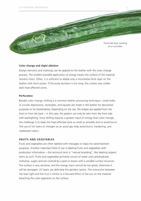
↑CONTENT
↑CONTENT
2 . 4 NATUR AL MATER IALS
Color change and slight ablation
Design elements and markings can be applied to the leather with the color change
process. The smallest possible application of energy means the surface of the material
remains intact. Often, it is sufficient to ablate only a micrometer-thick layer on the
leather with short pulses. If the pulse duration is too long, this creates very visible,
dark heat-affected zones.
Perforation
Besides color change, drilling is a common leather processing technique — small holes
or circular depressions, rectangles, and squares are made in the leather for decorative
purposes or for breathability. Depending on the use, the shapes are applied from the
front or from the back — in this case, the pattern can only be seen from the front side
with backlighting. Since drilling requires a greater input of energy than color change,
the challenge is to keep the heat-affected zone as small as possible and to avoid burns.
The use of UV lasers or nitrogen as an assist gas help avoid burns, hardening, and
unpleasant odors.
FRUITS AND VEGETABLES
Fruits and vegetables are often labeled with messages or logos for advertisement
purposes. Another important field of use is labeling fruits and vegetables with
production information — the technical term is “natural branding”, like labeling organic
items as such. Fruits and vegetables primarily consist of water and carbohydrates
(cellulose, sugar) and are covered by a peel or leaves with a variable surface structure.
The surface is very sensitive, and the energy input cannot be too great, otherwise it
will be damaged. UV lasers are definitely the gentlest option. The interaction between
the laser light and the fruit is similar to a focused effect of the sun on the material:
bleaching the color pigments on the surface.
Food-safe laser marking
on a cucumber.
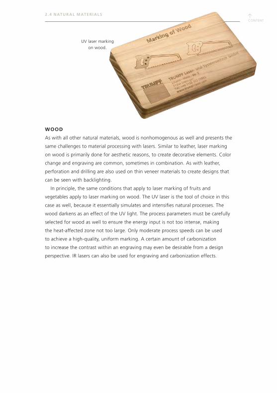
↑CONTENT
2 . 4 NATUR AL MATER IALS
UV laser marking
on wood.
WOOD
As with all other natural materials, wood is nonhomogenous as well and presents the
same challenges to material processing with lasers. Similar to leather, laser marking
on wood is primarily done for aesthetic reasons, to create decorative elements. Color
change and engraving are common, sometimes in combination. As with leather,
perforation and drilling are also used on thin veneer materials to create designs that
can be seen with backlighting.
In principle, the same conditions that apply to laser marking of fruits and
vegetables apply to laser marking on wood. The UV laser is the tool of choice in this
case as well, because it essentially simulates and intensifies natural processes. The
wood darkens as an effect of the UV light. The process parameters must be carefully
selected for wood as well to ensure the energy input is not too intense, making
the heat-affected zone not too large. Only moderate process speeds can be used
to achieve a high-quality, uniform marking. A certain amount of carbonization
to increase the contrast within an engraving may even be desirable from a design
perspective. IR lasers can also be used for engraving and carbonization effects.
↑CONTENT
↑CONTENT
2 .5 PROCESS PAR AMETERS
2.5 PROCESS PARAMETERS
Is a marking laser economical for a certain application? There are two important
factors in answering this question: process speed and quality. Process speed can
simply be measured in time, and the following criteria apply to quality:
• Contrast: The marking should stand out well from the color of the
base material.
• Homogenity: The color of the marking should be uniform over the entire
typeface area.
• Contour accuracy and sharpness of detail: The contours of the marking
should match the required design as closely as possible. Details must be
replicated sufficiently.
• Positioning accuracy: The position of the marking should match the
required value.
• Durability: The marking must be resistant to scratches and abrasions.
It cannot have microcracks and must be resistant to corrosion.
• Absence of burrs: High-quality engravings often must not have any burrs,
otherwise reworking will be necessary.
How can the desired quality be achieved? By balancing the interaction of the essential
process parameters. These are presented below.
PULSE REPETITION FREQUENCY / REPETITION RATE
In short-pulse lasers, the pulse frequency determines the frequency of pulse repetition.
They go from several kilo- up to the megahertz range. For Q-switched solid-state lasers,
the following rule applies: For high repetition rates, the pulse duration is longer and
the peak pulse power is low. The pulse duration is shorter and the peak pulse power is
high when the repetition rate is low.
PULSE LENGTH
The pulse duration is the time between the beginning and the end of an impulse
measured in seconds. Marking lasers usually have a pulse duration in the nano-,
pico-, or femtosecond range. For fiber lasers that are designed as oscillator amplifier
systems (MOFPA), pulse duration adjustment is more flexible with respect to the pulse
repetition frequency, because the pulse duration is determined by the seed pulse.
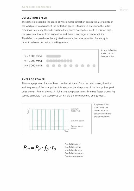
↑CONTENT
2 .5 PROCESS PAR AMETERS
DEFLECTION SPEED
The deflection speed is the speed at which mirror deflection causes the laser points on
the workpiece to advance. If the deflection speed is too low in relation to the pulse
repetition frequency, the individual marking points overlap too much. If it is too high,
the points are too far from each other and there is no longer a connected line.
The deflection speed must be adjusted to match the pulse repetition frequency in
order to achieve the desired marking results.
AVERAGE POWER
The average power of a laser beam can be calculated from the peak power, duration,
and frequency of the laser pulses. It is always under the power of the laser pulses (peak
pulse power). Rule of thumb: A higher average power normally makes faster processing
speeds possiblee, if the workpiece can handle the corresponding energy input.
At low deflection
speeds, points
become a line.
Pp = Pulse power
Ep = Pulse energy
tp = Pulse duration
ƒp = Pulse frequency
Pm = Average power
For pulsed solid-
state lasers the
maximum pulse
power exceeds the
excitation power.
Pm = Ep = Pp · tp Pp · ƒp · tp
Maximum pulse power
Excitation power
Average output power
Time
Pow
er
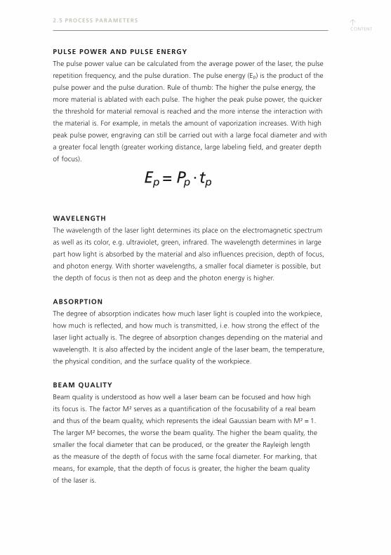
↑CONTENT
↑CONTENT
2 .5 PROCESS PAR AMETERS
PULSE POWER AND PULSE ENERGY
The pulse power value can be calculated from the average power of the laser, the pulse
repetition frequency, and the pulse duration. The pulse energy (Ep) is the product of the
pulse power and the pulse duration. Rule of thumb: The higher the pulse energy, the
more material is ablated with each pulse. The higher the peak pulse power, the quicker
the threshold for material removal is reached and the more intense the interaction with
the material is. For example, in metals the amount of vaporization increases. With high
peak pulse power, engraving can still be carried out with a large focal diameter and with
a greater focal length (greater working distance, large labeling field, and greater depth
of focus).
WAVELENGTH
The wavelength of the laser light determines its place on the electromagnetic spectrum
as well as its color, e.g. ultraviolet, green, infrared. The wavelength determines in large
part how light is absorbed by the material and also influences precision, depth of focus,
and photon energy. With shorter wavelengths, a smaller focal diameter is possible, but
the depth of focus is then not as deep and the photon energy is higher.
ABSORPTION
The degree of absorption indicates how much laser light is coupled into the workpiece,
how much is reflected, and how much is transmitted, i.e. how strong the effect of the
laser light actually is. The degree of absorption changes depending on the material and
wavelength. It is also affected by the incident angle of the laser beam, the temperature,
the physical condition, and the surface quality of the workpiece.
BEAM QUALITY
Beam quality is understood as how well a laser beam can be focused and how high
its focus is. The factor M² serves as a quantification of the focusability of a real beam
and thus of the beam quality, which represents the ideal Gaussian beam with M² = 1.
The larger M² becomes, the worse the beam quality. The higher the beam quality, the
smaller the focal diameter that can be produced, or the greater the Rayleigh length
as the measure of the depth of focus with the same focal diameter. For marking, that
means, for example, that the depth of focus is greater, the higher the beam quality
of the laser is.
Pm = Ep = Pp · tp Pp · ƒp · tp

↑CONTENT
d0
Focal length ƒ
2 zRƒ
zRƒ
dƒ√2 rƒ―
Ф(z) z
2 .5 PROCESS PAR AMETERS
FOCAL LENGTH
The focal length of the focusing optics indicates the distance between the center of the
optics and the focal point of an ideal parallel beam and thus determines the working
distance between the laser and workpiece. Rule of thumb: The shorter the focal length,
the stronger the beam is focused and the smaller the focal diameter and Rayleigh
length. However, the marking field size also changes. The shorter the focal length,
the smaller the labeling field.
RAYLEIGH LENGTH AND DEPTH OF FOCUS
The beam expands according to the focus. The Rayleigh length indicates the distance
to the focus at which the beam cross-section area doubles and the intensity is halved.
The doubled Rayleigh length is often referred to as depth of focus. For example, a large
depth of focus allows for a high positioning tolerance of the workpiece or the marking
of curved surfaces.
FOCAL DIAMETER
The focal diameter is the place where the laser beam has its smallest cross section.
Rule of thumb: The smaller the focal diameter, the higher the power density in the focal
point. However, this must be adapted to the procedure. And the smaller the focus area,
the finer and more precise the material can be processed.
dƒ = · · —4·λ
π —ƒd0
M 2
dƒ = Focal diameter
λ = Wavelength
ƒ = Focal length
d0 = Raw beam diameter
at focal lens
M2 = Beam quality
zRƒ = Rayleighlength
dƒ = Focal diameter
λ = Wavelength
M2 = Beam quality
zRƒ = · · —4·λ
π —1dƒ2
M2
↑CONTENT
↑CONTENT
2 .5 PROCESS PAR AMETERS
FOCUS POSITION
Ideally, the focus should be exactly on the workpiece surface — this is influenced by the
working distance and focal length. Whether the focus deviates from its ideal position
during marking is critical or less critical, depending on the material and process, but can
also be desired, for example to achieve larger line widths or to reduce the energy density
of sensitive materials, for example to produce annealing marks and to only heat the
material.
PROCESSING GEOMETRY (LINE SPACING, HATCHING)
Each instance of processing leaves a wider or narrower track with a specific geometry in
the material. This does not have to correspond exactly to the focal diameter, but must be
taken into account, for example, when marking bar codes or Data Matrix Codes with a
certain correction distance in the module size. With filled contours, lines with a certain
line spacing (or possibly also a line overlap) are juxtaposed. The area energy and thus
also the process result can be adjusted by different distances of the hatches.
ENERGY DENSITY (FLUENCE)
Fluence is the energy over the area of a laser pulse. Together with absorption, it
determines how strongly laser light and material interact. Depending on the material,
a certain threshold fluence must be exceeded so that the material can be ablated by
the laser (ablation threshold).
POWER DENSITY ( INTENSITY)
The power density a laser beam — also called intensity — is the power per area; it is
highest in the focal point. Higher power and smaller focal diameters produce a higher
irradiance. This allows high processing speeds to be achieved.
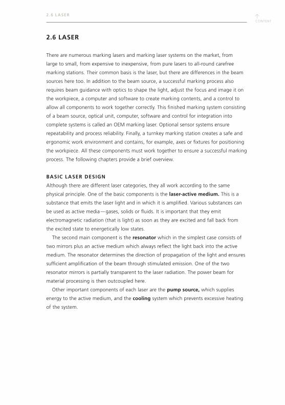
↑CONTENT
2.6 LASER
There are numerous marking lasers and marking laser systems on the market, from
large to small, from expensive to inexpensive, from pure lasers to all-round carefree
marking stations. Their common basis is the laser, but there are differences in the beam
sources here too. In addition to the beam source, a successful marking process also
requires beam guidance with optics to shape the light, adjust the focus and image it on
the workpiece, a computer and software to create marking contents, and a control to
allow all components to work together correctly. This finished marking system consisting
of a beam source, optical unit, computer, software and control for integration into
complete systems is called an OEM marking laser. Optional sensor systems ensure
repeatability and process reliability. Finally, a turnkey marking station creates a safe and
ergonomic work environment and contains, for example, axes or fixtures for positioning
the workpiece. All these components must work together to ensure a successful marking
process. The following chapters provide a brief overview.
BASIC LASER DESIGN
Although there are different laser categories, they all work according to the same
physical principle. One of the basic components is the laser-active medium. This is a
substance that emits the laser light and in which it is amplified. Various substances can
be used as active media — gases, solids or fluids. It is important that they emit
electromagnetic radiation (that is light) as soon as they are excited and fall back from
the excited state to energetically low states.
The second main component is the resonator which in the simplest case consists of
two mirrors plus an active medium which always reflect the light back into the active
medium. The resonator determines the direction of propagation of the light and ensures
sufficient amplification of the beam through stimulated emission. One of the two
resonator mirrors is partially transparent to the laser radiation. The power beam for
material processing is then outcoupled here.
Other important components of each laser are the pump source, which supplies
energy to the active medium, and the cooling system which prevents excessive heating
of the system.
2 .6 L ASER
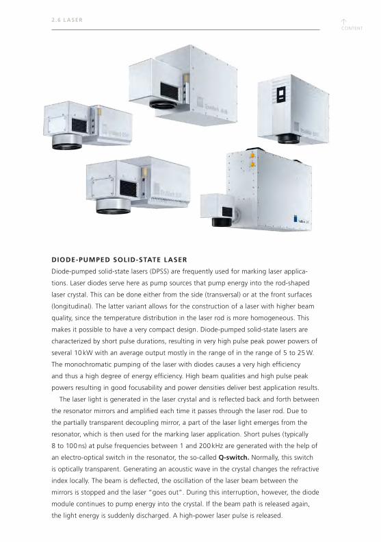
↑CONTENT
↑CONTENT
2 .6 L ASER
DIODE-PUMPED SOLID-STATE LASER
Diode-pumped solid-state lasers (DPSS) are frequently used for marking laser applica-
tions. Laser diodes serve here as pump sources that pump energy into the rod-shaped
laser crystal. This can be done either from the side (transversal) or at the front surfaces
(longitudinal). The latter variant allows for the construction of a laser with higher beam
quality, since the temperature distribution in the laser rod is more homogeneous. This
makes it possible to have a very compact design. Diode-pumped solid-state lasers are
characterized by short pulse durations, resulting in very high pulse peak power powers of
several 10 kW with an average output mostly in the range of in the range of 5 to 25 W.
The monochromatic pumping of the laser with diodes causes a very high efficiency
and thus a high degree of energy efficiency. High beam qualities and high pulse peak
powers resulting in good focusability and power densities deliver best application results.
The laser light is generated in the laser crystal and is reflected back and forth between
the resonator mirrors and amplified each time it passes through the laser rod. Due to
the partially transparent decoupling mirror, a part of the laser light emerges from the
resonator, which is then used for the marking laser application. Short pulses (typically
8 to 100 ns) at pulse frequencies between 1 and 200 kHz are generated with the help of
an electro-optical switch in the resonator, the so-called Q-switch. Normally, this switch
is optically transparent. Generating an acoustic wave in the crystal changes the refractive
index locally. The beam is deflected, the oscillation of the laser beam between the
mirrors is stopped and the laser “goes out”. During this interruption, however, the diode
module continues to pump energy into the crystal. If the beam path is released again,
the light energy is suddenly discharged. A high-power laser pulse is released.
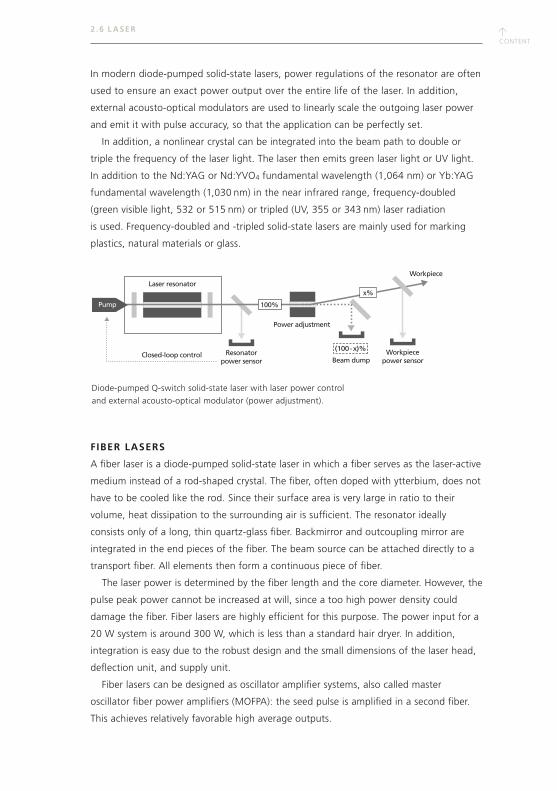
↑CONTENT
In modern diode-pumped solid-state lasers, power regulations of the resonator are often
used to ensure an exact power output over the entire life of the laser. In addition,
external acousto-optical modulators are used to linearly scale the outgoing laser power
and emit it with pulse accuracy, so that the application can be perfectly set.
In addition, a nonlinear crystal can be integrated into the beam path to double or
triple the frequency of the laser light. The laser then emits green laser light or UV light.
In addition to the Nd:YAG or Nd:YVO4 fundamental wavelength (1,064 nm) or Yb:YAG
fundamental wavelength (1,030 nm) in the near infrared range, frequency-doubled
(green visible light, 532 or 515 nm) or tripled (UV, 355 or 343 nm) laser radiation
is used. Frequency-doubled and -tripled solid-state lasers are mainly used for marking
plastics, natural materials or glass.
FIBER LASERS
A fiber laser is a diode-pumped solid-state laser in which a fiber serves as the laser-active
medium instead of a rod-shaped crystal. The fiber, often doped with ytterbium, does not
have to be cooled like the rod. Since their surface area is very large in ratio to their
volume, heat dissipation to the surrounding air is sufficient. The resonator ideally
consists only of a long, thin quartz-glass fiber. Backmirror and outcoupling mirror are
integrated in the end pieces of the fiber. The beam source can be attached directly to a
transport fiber. All elements then form a continuous piece of fiber.
The laser power is determined by the fiber length and the core diameter. However, the
pulse peak power cannot be increased at will, since a too high power density could
damage the fiber. Fiber lasers are highly efficient for this purpose. The power input for a
20 W system is around 300 W, which is less than a standard hair dryer. In addition,
integration is easy due to the robust design and the small dimensions of the laser head,
deflection unit, and supply unit.
Fiber lasers can be designed as oscillator amplifier systems, also called master
oscillator fiber power amplifiers (MOFPA): the seed pulse is amplified in a second fiber.
This achieves relatively favorable high average outputs.
2 .6 L ASER
(100-x)%
Laser resonator
Power adjustment
Pump
Resonatorpower sensor Beam dump
100%
x%
Workpiecepower sensor
Workpiece
Closed-loop control
Diode-pumped Q-switch solid-state laser with laser power control
and external acousto-optical modulator (power adjustment).
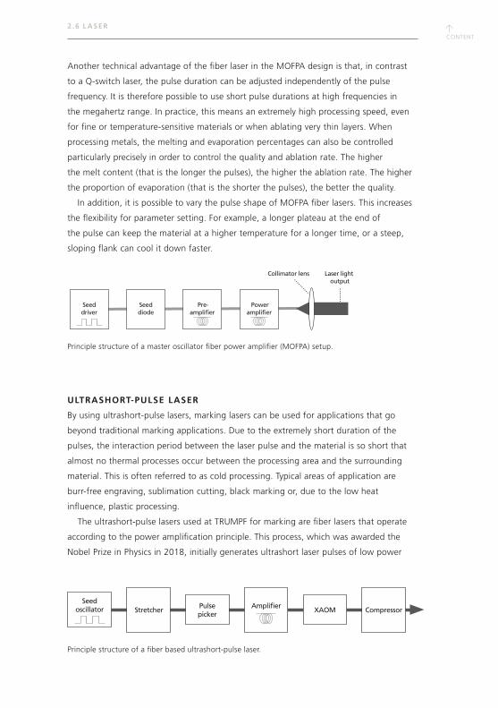
↑CONTENT
↑CONTENT
2 .6 L ASER
Another technical advantage of the fiber laser in the MOFPA design is that, in contrast
to a Q-switch laser, the pulse duration can be adjusted independently of the pulse
frequency. It is therefore possible to use short pulse durations at high frequencies in
the megahertz range. In practice, this means an extremely high processing speed, even
for fine or temperature-sensitive materials or when ablating very thin layers. When
processing metals, the melting and evaporation percentages can also be controlled
particularly precisely in order to control the quality and ablation rate. The higher
the melt content (that is the longer the pulses), the higher the ablation rate. The higher
the proportion of evaporation (that is the shorter the pulses), the better the quality.
In addition, it is possible to vary the pulse shape of MOFPA fiber lasers. This increases
the flexibility for parameter setting. For example, a longer plateau at the end of
the pulse can keep the material at a higher temperature for a longer time, or a steep,
sloping flank can cool it down faster.
ULTRASHORT-PULSE LASER
By using ultrashort-pulse lasers, marking lasers can be used for applications that go
beyond traditional marking applications. Due to the extremely short duration of the
pulses, the interaction period between the laser pulse and the material is so short that
almost no thermal processes occur between the processing area and the surrounding
material. This is often referred to as cold processing. Typical areas of application are
burr-free engraving, sublimation cutting, black marking or, due to the low heat
influence, plastic processing.
The ultrashort-pulse lasers used at TRUMPF for marking are fiber lasers that operate
according to the power amplification principle. This process, which was awarded the
Nobel Prize in Physics in 2018, initially generates ultrashort laser pulses of low power
StretcherPulsepicker
XAOM CompressorSeed
oscillator Amplifier
Seeddriver
Seeddiode
Pre-amplifier
Poweramplifier
Laser light output
Collimator lens
Principle structure of a fiber based ultrashort-pulse laser.
Principle structure of a master oscillator fiber power amplifier (MOFPA) setup.
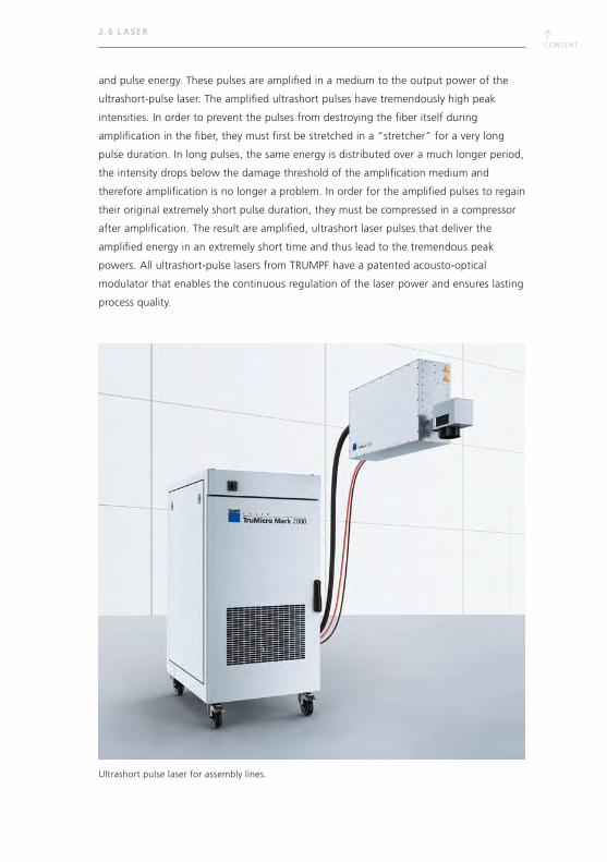
↑CONTENT
and pulse energy. These pulses are amplified in a medium to the output power of the
ultrashort-pulse laser. The amplified ultrashort pulses have tremendously high peak
intensities. In order to prevent the pulses from destroying the fiber itself during
amplification in the fiber, they must first be stretched in a “stretcher” for a very long
pulse duration. In long pulses, the same energy is distributed over a much longer period,
the intensity drops below the damage threshold of the amplification medium and
therefore amplification is no longer a problem. In order for the amplified pulses to regain
their original extremely short pulse duration, they must be compressed in a compressor
after amplification. The result are amplified, ultrashort laser pulses that deliver the
amplified energy in an extremely short time and thus lead to the tremendous peak
powers. All ultrashort-pulse lasers from TRUMPF have a patented acousto-optical
modulator that enables the continuous regulation of the laser power and ensures lasting
process quality.
2 .6 L ASER
Ultrashort pulse laser for assembly lines.
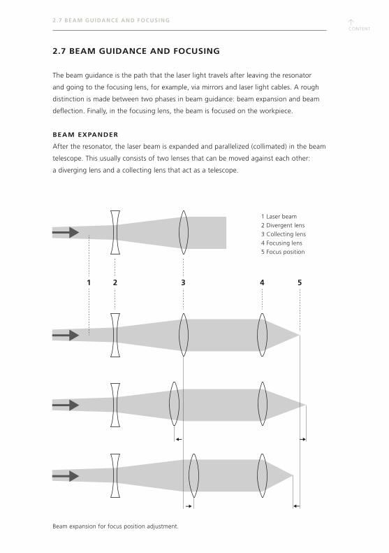
↑CONTENT
↑CONTENT
2 .7 BEAM GUIDANCE AND FOCUSING
2.7 BEAM GUIDANCE AND FOCUSING
The beam guidance is the path that the laser light travels after leaving the resonator
and going to the focusing lens, for example, via mirrors and laser light cables. A rough
distinction is made between two phases in beam guidance: beam expansion and beam
deflection. Finally, in the focusing lens, the beam is focused on the workpiece.
BEAM EXPANDER
After the resonator, the laser beam is expanded and parallelized (collimated) in the beam
telescope. This usually consists of two lenses that can be moved against each other:
a diverging lens and a collecting lens that act as a telescope.
1 Laser beam
2 Divergent lens
3 Collecting lens
4 Focusing lens
5 Focus position
1 2 3 4 5
Beam expansion for focus position adjustment.
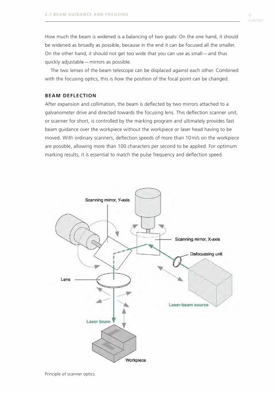
↑CONTENT
2 .7 BEAM GUIDANCE AND FOCUSING
How much the beam is widened is a balancing of two goals: On the one hand, it should
be widened as broadly as possible, because in the end it can be focused all the smaller.
On the other hand, it should not get too wide that you can use as small — and thus
quickly adjustable — mirrors as possible.
The two lenses of the beam telescope can be displaced against each other. Combined
with the focusing optics, this is how the position of the focal point can be changed.
BEAM DEFLECTION
After expansion and collimation, the beam is deflected by two mirrors attached to a
galvanometer drive and directed towards the focusing lens. This deflection scanner unit,
or scanner for short, is controlled by the marking program and ultimately provides fast
beam guidance over the workpiece without the workpiece or laser head having to be
moved. With ordinary scanners, deflection speeds of more than 10 m/s on the workpiece
are possible, allowing more than 100 characters per second to be applied. For optimum
marking results, it is essential to match the pulse frequency and deflection speed.
Principle of scanner optics.
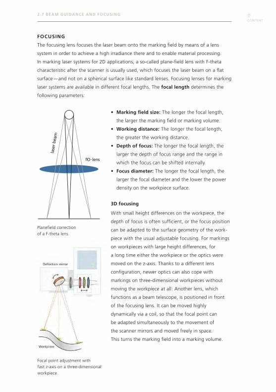
↑CONTENT
↑CONTENT
lase
r be
am
fO-lens-
2 .7 BEAM GUIDANCE AND FOCUSING
Planefield correction
of a F-theta lens.
Focal point adjustment with
fast z-axis on a three-dimensional
workpiece.
FOCUSING
The focusing lens focuses the laser beam onto the marking field by means of a lens
system in order to achieve a high irradiance there and to enable material processing.
In marking laser systems for 2D applications, a so-called plane-field lens with F-theta
characteristic after the scanner is usually used, which focuses the laser beam on a flat
surface — and not on a spherical surface like standard lenses. Focusing lenses for marking
laser systems are available in different focal lengths. The focal length determines the
following parameters:
• Marking field size: The longer the focal length,
the larger the marking field or marking volume.
• Working distance: The longer the focal length,
the greater the working distance.
• Depth of focus: The longer the focal length, the
larger the depth of focus range and the range in
which the focus can be shifted internally.
• Focus diameter: The longer the focal length, the
larger the focal diameter and the lower the power
density on the workpiece surface.
3D focusing
With small height differences on the workpiece, the
depth of focus is often sufficient, or the focus position
can be adapted to the surface geometry of the work-
piece with the usual adjustable focusing. For markings
on workpieces with large height differences, for
a long time either the workpiece or the optics were
moved on the z-axis. Thanks to a different lens
configuration, newer optics can also cope with
markings on three-dimensional workpieces without
moving the workpiece at all: Another lens, which
functions as a beam telescope, is positioned in front
of the focusing lens. It can be moved highly
dynamically via a coil, so that the focal point can
be adapted simultaneously to the movement of
the scanner mirrors and moved freely in space.
This turns the marking field into a marking volume.

↑CONTENT
2 . 8 MARKING SYSTEMS
2.8 MARKING SYSTEMS
The spectrum of laser marker systems ranges from mobile laser devices to automated
processing stations. Small, cost-effective solutions and fully equipped, high-end systems
offer the right solution for every requirement, depending on the marking task, the
component volume and the lot size. The laser marker systems do not differ significantly
in their basic structure. The following describes which components belong to a marking
laser system and which equipment is necessary for different applications.
LASER CLASS 1
Marking lasers must be certified according to laser class 1 so that they can be used
without additional safety measures. Sophisticated safety concepts with intelligent
monitoring sensors ensure this at all times. The work area is secured by a safety door
that closes during marking and guarantees safe working. A coated safety window,
specially designed for the corresponding wavelength, can be installed in the housing to
provide viewing.
EXHAUST SYSTEM
Particles that damage the lungs when inhaled can occur, especially during ablative
engraving. That is why exhaust systems are required in laser marking systems. The filter
system consists of a prefilter and a particle filter with activated carbon. The exhaust
nozzle sucks in vapors and particles, which are then fed into the filter pack via a hose.
Using suitable software, the exhaust system can be switched on with the marking
system and switched off again after the control program has ended.
AXES
The z-axis supports the positioning of the laser head and the setting of the exact focus
position. The machining process can be adapted to the component requirements by
using other optionally available axis systems. For example, when marking larger surfaces,
it may be necessary to move the part in two directions — this is referred to as surface
segmentation. The workpiece holders are mounted on linear axes. Optional rotary axes
allow for marking, even on cylindrical workpieces (rotary axis segmentation).
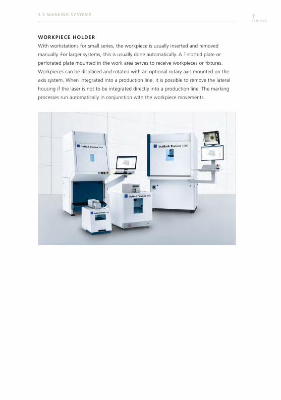
↑CONTENT
↑CONTENT
2 . 8 MARKING SYSTEMS
WORKPIECE HOLDER
With workstations for small series, the workpiece is usually inserted and removed
manually. For larger systems, this is usually done automatically. A T-slotted plate or
perforated plate mounted in the work area serves to receive workpieces or fixtures.
Workpieces can be displaced and rotated with an optional rotary axis mounted on the
axis system. When integrated into a production line, it is possible to remove the lateral
housing if the laser is not to be integrated directly into a production line. The marking
processes run automatically in conjunction with the workpiece movements.
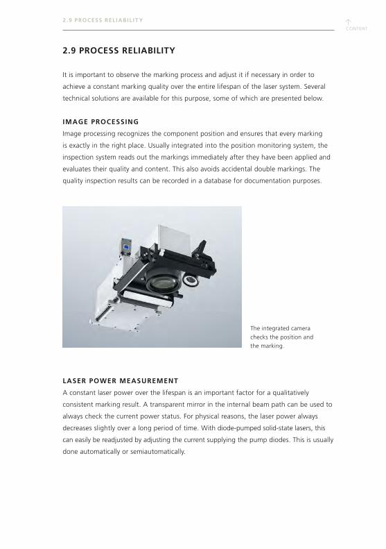
↑CONTENT
2 .9 PROCESS REL IAB IL IT Y
2.9 PROCESS RELIABILITY
It is important to observe the marking process and adjust it if necessary in order to
achieve a constant marking quality over the entire lifespan of the laser system. Several
technical solutions are available for this purpose, some of which are presented below.
IMAGE PROCESSING
Image processing recognizes the component position and ensures that every marking
is exactly in the right place. Usually integrated into the position monitoring system, the
inspection system reads out the markings immediately after they have been applied and
evaluates their quality and content. This also avoids accidental double markings. The
quality inspection results can be recorded in a database for documentation purposes.
LASER POWER MEASUREMENT
A constant laser power over the lifespan is an important factor for a qualitatively
consistent marking result. A transparent mirror in the internal beam path can be used to
always check the current power status. For physical reasons, the laser power always
decreases slightly over a long period of time. With diode-pumped solid-state lasers, this
can easily be readjusted by adjusting the current supplying the pump diodes. This is usually
done automatically or semiautomatically.
The integrated camera
checks the position and
the marking.

↑CONTENT
↑CONTENT
2 .9 PROCESS REL IAB IL IT Y
LASER POWER CONTROL
If the ambient temperature fluctuates, this can also have an effect on the laser power
and thus on the marking result. A modern laser power control therefore decouples a
defined percentage of laser power from the beam path inline and measures it using
photodiodes. A control circuit then automatically adjusts the pump power of the diodes,
so that marking quality stays constant for the entire service life.
CONDITION BASED MONITORING
Sensor systems and the appropriate interfaces for reading out various information, such
as the TruMark OPC/UA interface Condition Based Monitoring, are used to achieve a
continuous and comprehensive status analysis of the laser and marking process in the
sense of Industry 4.0. This information includes laser condition data and process
parameters such as laser power or air temperature during cooling. Warning messages
indicate the need for action at an early stage, and error messages become visible
immediately — in this way, failures can be rectified quickly or even avoided altogether,
preventing unexpected interruptions in production.
↑CONTENT

↑CONTENT
↑CONTENT
3. PRACTICAL MARKING
So you have chosen your materials and decided which marking process you need to use.
Now comes the practical stage: when switching on your TRUMPF marking laser system,
the TruTops Mark control software starts up automatically via the control computer.
The intuitive user interface makes it easier to access the following:
CAD editor
Setting and management of laser parameters
Interfaces
Easy marking on the fly
Sequence programming
Diagnostics tool
This set of tools enables you to carry out all of the steps required for applying the
marking content to the workpiece.
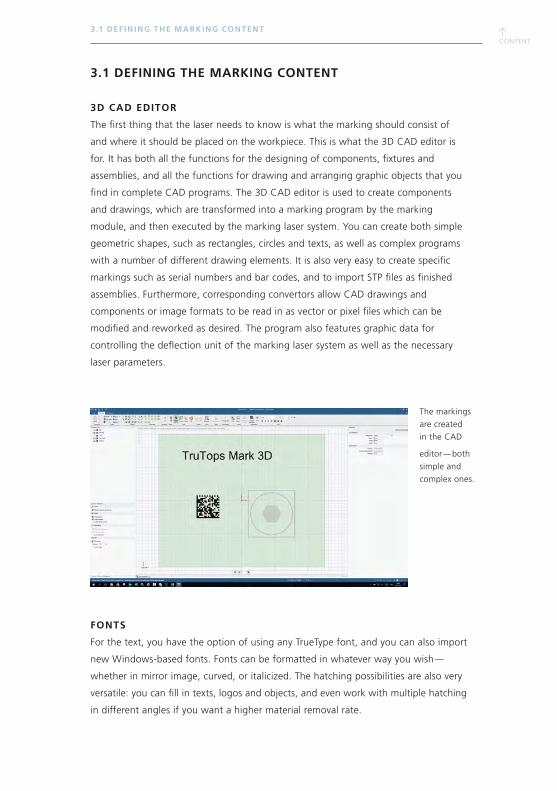
↑CONTENT
3.1 DEFINING THE MARKING CONTENT
3D CAD EDITOR
The first thing that the laser needs to know is what the marking should consist of
and where it should be placed on the workpiece. This is what the 3D CAD editor is
for. It has both all the functions for the designing of components, fixtures and
assemblies, and all the functions for drawing and arranging graphic objects that you
find in complete CAD programs. The 3D CAD editor is used to create components
and drawings, which are transformed into a marking program by the marking
module, and then executed by the marking laser system. You can create both simple
geometric shapes, such as rectangles, circles and texts, as well as complex programs
with a number of different drawing elements. It is also very easy to create specific
markings such as serial numbers and bar codes, and to import STP files as finished
assemblies. Furthermore, corresponding convertors allow CAD drawings and
components or image formats to be read in as vector or pixel files which can be
modified and reworked as desired. The program also features graphic data for
controlling the deflection unit of the marking laser system as well as the necessary
laser parameters.
FONTS
For the text, you have the option of using any TrueType font, and you can also import
new Windows-based fonts. Fonts can be formatted in whatever way you wish —
whether in mirror image, curved, or italicized. The hatching possibilities are also very
versatile: you can fill in texts, logos and objects, and even work with multiple hatching
in different angles if you want a higher material removal rate.
The markings
are created
in the CAD
editor — both
simple and
complex ones.
3 .1 DEF IN ING THE MARKING CONTENT
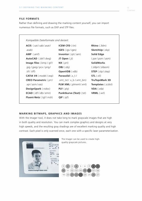
↑CONTENT
↑CONTENT
FILE FORMATS
Rather than defining and drawing the marking content yourself, you can import
numerous file formats, such as DXF and STP files.
MARKING BITMAPS, GRAPHICS AND IMAGES
With the Imager tool, it does not take long to mark grayscale images that are high
in both quality and resolution. You can mark complex graphics and designs at very
high speeds, and the resulting gray shadings are of excellent marking quality and high
contrast. Each pixel is only scanned once, each one with a specific laser parameterization.
The Imager can be used to create high-
quality grayscale pictures.
3 .1 DEF IN ING THE MARKING CONTENT
1 62 73 84 95
10 1511 1612 1713 1814
19 2420 2521 2622 2723
Kompatible Dateiformate sind derzeit:
ACIS (.sat /.sab /.asat /
.asab)
AMF (.amf)
AutoCAD (.dxf /.dwg)
Image files (.bmp /.gif /
.jpg /.jpeg /.pcx /.png /
.tif / .tiff)
CATIA V4 (.model /.exp)
CREO Parametric (.prt /
.xpr /.asm /.xas)
DesignSpark (.rsdoc)
ECAD (.idf /.idb /.emn)
Fluent-Netz (.tgf /.msh)
ICEM CFD (.tin)
IGES (.igs /.iges)
Inventor (.ipt /.iam)
JT Open (.jt)
NX (.prt)
OBJ (.obj)
OpenVDB (.vdb)
Parasolid (.x_t /
.xmt_txt / .x_b /.xmt_bin)
PLM XML (.plmxml /.xml)
PLY (.ply)
Punktkurve (Text) (.txt)
QIF (.qif)
Rhino (.3dm)
SketchUp (.skp)
Solid Edge
(.par /.psm /.asm)
SolidWorks
(.sldprt /.sldasm)
STEP (.stp /.step)
STL (.stl)
TruTopsMark 3D
Templates (.scdot)
VDA (.vda)
VRML (.wrl)
↑CONTENT
3 .1 DEF IN ING THE MARKING CONTENT
VARIABLES
The text or value used in the data object can be defined as a fixed and invariable object
(“static object”) or as a variable. Variables (e.g., serial numbers) are not filled with the
content until the marking stage. When you run the marking program, the variable text is
generated from constants, a keyword (such as the current date), a serial number, or a
variable that has already been created. You can either merge several objects together
(keywords, constants, variable), or transfer the variable directly to the marking system
via the external interface.
BAR CODES
The variable data can simply be coded as a one- or two-dimensional bar code. Bar code
types differ in terms of the symbols that can be used, the coding, and the length of
the desired text. With TruTops Mark, it is possible to generate numerous different bar
codes, square and rectangular Data Matrix Codes and DMRE codes (also in accordance
with the GS1 standard), and QR codes. Together they form a sequence of different
symbol sizes, with which you can code small and large amounts of data efficiently.
The laser can select the formats automatically, and scanning devices are able to
differentiate between them automatically.
CONTROL WITH EXTERNAL DATA COMMUNICATION
TruTops Mark can be controlled via different interfaces using external data communication.
The integrated interface can be used to incorporate variable production data online into
a predefined marking program. With TruTops Mark, you have the following options for the
control-side integration of the marking laser system into existing manufacturing systems:
TLV
Digital I/O
TCP/IP
Profibus
Profinet
EtherNet/IP
EtherCAT
ACTIVEX TRUTOPS MARK COMPONENT
The ActiveX software component for TruTops Mark facilitates integration by means of
ActiveX data exchange. Predefined tag-length-value commands can simply be integrated
into the customer’s process environment.

↑CONTENT
↑CONTENT
3 . 2 AL IGNING THE POSIT ION
3.2 ALIGNING THE POSITION
The marking field is the area that the laser is able to mark, i.e. the area that is covered
by the scanner. The size of the marking field depends on the machine configuration
and is set in the marking interface according to the chosen optics.
Using 3D hardware (TruMark 6030), it is possible to generate markings on 3D surfaces —
in this case, a marking field becomes a marking volume with an additional z-component.
A suitable workpiece holder for the components ensures that these are always in
exactly the right position. However, this type of fixture is not needed every time, as the
marking application is noncontact and thus, does not apply any force to the component.
With the pilot laser, it is very easy to align the marking. The pilot laser emits a
low-power red light via the laser optics. For the positioning, the marking processes are
simulated on the workpiece using the pilot laser, before the actual marking is applied.
For the positioning,
the pilot laser simulates
the marking.
Wrapped marking
content for a 3D marking.
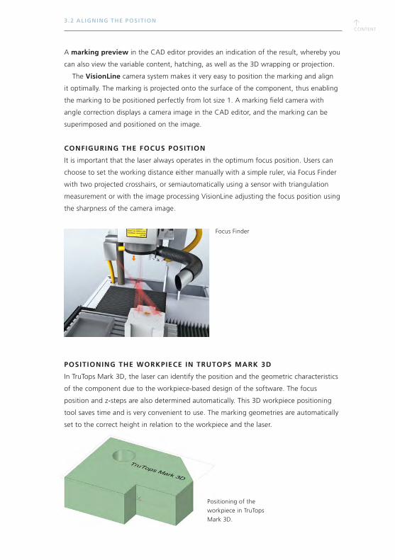
↑CONTENT
3 . 2 AL IGNING THE POSIT ION
A marking preview in the CAD editor provides an indication of the result, whereby you
can also view the variable content, hatching, as well as the 3D wrapping or projection.
The VisionLine camera system makes it very easy to position the marking and align
it optimally. The marking is projected onto the surface of the component, thus enabling
the marking to be positioned perfectly from lot size 1. A marking field camera with
angle correction displays a camera image in the CAD editor, and the marking can be
superimposed and positioned on the image.
CONFIGURING THE FOCUS POSITION
It is important that the laser always operates in the optimum focus position. Users can
choose to set the working distance either manually with a simple ruler, via Focus Finder
with two projected crosshairs, or semiautomatically using a sensor with triangulation
measurement or with the image processing VisionLine adjusting the focus position using
the sharpness of the camera image.
POSITIONING THE WORKPIECE IN TRUTOPS MARK 3D
In TruTops Mark 3D, the laser can identify the position and the geometric characteristics
of the component due to the workpiece-based design of the software. The focus
position and z-steps are also determined automatically. This 3D workpiece positioning
tool saves time and is very convenient to use. The marking geometries are automatically
set to the correct height in relation to the workpiece and the laser.
Focus Finder
Positioning of the
workpiece in TruTops
Mark 3D.
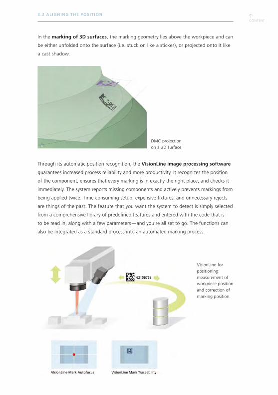
↑CONTENT
↑CONTENT
3 . 2 AL IGNING THE POSIT ION
In the marking of 3D surfaces, the marking geometry lies above the workpiece and can
be either unfolded onto the surface (i.e. stuck on like a sticker), or projected onto it like
a cast shadow.
Through its automatic position recognition, the VisionLine image processing software
guarantees increased process reliability and more productivity. It recognizes the position
of the component, ensures that every marking is in exactly the right place, and checks it
immediately. The system reports missing components and actively prevents markings from
being applied twice. Time-consuming setup, expensive fixtures, and unnecessary rejects
are things of the past. The feature that you want the system to detect is simply selected
from a comprehensive library of predefined features and entered with the code that is
to be read in, along with a few parameters — and you’re all set to go. The functions can
also be integrated as a standard process into an automated marking process.
DMC projection
on a 3D surface.
VisionLine for
positioning:
measurement of
workpiece position
and correction of
marking position.
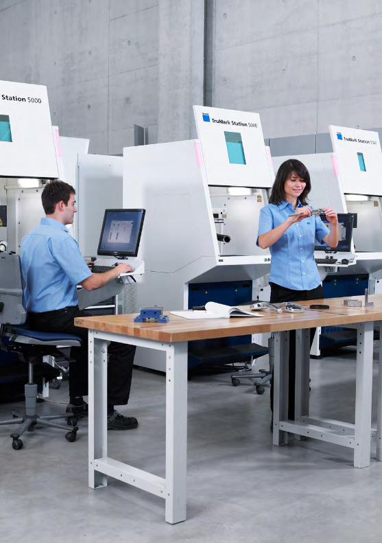
↑CONTENT

↑CONTENT
↑CONTENT
3 . 3 SELEC T ING THE PAR AMETERS
3.3 SELECTING THE PARAMETERS
NAVIGATOR
The Navigator assists users in finding the right laser parameters for their marking task
in the fastest way possible. The only thing left to do is to choose the material that you
want to mark. Each type of material is assigned to one or more different processes
(e.g., engraving, annealing, color change). The objects that are marked as a test field
are freely selectable objects in freely selectable dimensions. The test field is marked
onto a workpiece. In this way, you can select the parameter with the required contrast
or desired quality for subsequent markings.
MAGIC 5
In the case of the Magic 5 option, the software already knows the physical characteristics
of the laser, and the configuration is stored automatically. This means that inexperienced
operators do not need any knowledge of lasers to apply markings. There is a slide control
bar that enables you to apply light-dark contrasts onto metal or plastic, without having to
adjust the individual laser parameters manually.
The Navigator
helps users
to find the
right laser
parameters.
Simple light-dark
contrasts using
the slide control bar
in Magic 5.

↑CONTENT
The software also features a parameters library/global parameters table via which
parameters that have been used once can be transferred to new marking files. This is also
possible for different types of hatching and variables, and accelerates the processing.
APPLICATION SERVICE
Processes are influenced by a host of different parameters, and knowing how to adjust
these parameters means you can optimize your processes accordingly. TRUMPF provides
users with personal assistance in this respect — either in our application centers, over the
phone with the Technical Service or on-site.
3 . 3 SELEC T ING THE PAR AMETERS
↑CONTENT
↑CONTENT
3 . 4 DEF IN ING THE PROCESSES
3.4 DEFINING THE PROCESSES
SEQUENCE PROGRAMMING
The sequence program can control all of the machine functions in connection with
a TruMark Station. These sequence programs can be written or changed via the editing
mode.
The visual software program QuickFlow was developed so that the process routine
is easy to create. Using a simple pick-and-drop system, you can create programs that
control the entire marking cycle from start to finish. You can also take advantage
of even more flexible and comprehensive possibilities, by using the WSTX sequence
programming used for the TruTops Mark Module Interface.
TRUTOPS MARK MODULE INTERFACE (TTM-MI)
This human-machine interface enables you to make specific adjustments to the software,
and is how communication is programmed between the laser (TruTops Mark) and other
systems, databases, tools, and robots.
Standardized module interfaces for different requirements are easy to incorporate
into any production process. These include:
Basic module for basic functions such as loading, saving, marking and axis
commands, variables, marking preview, status/errors, cycle time
Scanning module for scanning input data, multiple scan inputs, GS1 standard check
Database module for connecting to databases using the database assistant and
for running database commands (available: SQL Server, OLEDB, Oracle, MySQL,
SQLite, PSQL)
Camera module for the VisionLine functionality, autofocus function, reading out
function, etc.
Specific UDI module for marking medical devices, which enables the configuration
of the device identifier (DI) and production identifier (PI). This makes it possible to
produce UDI-Codes according to standards as GS1, HIBC oder ISBT 128.
If the standardized modules are not suitable, new modules can also be programmed
that are perfectly customized to your requirements.
In this way, users can use fully automated processes and profit from the elimination
of error sources. The entire process, including the process results, can be stored
in a database.
For more information about this process please see chapter 1.4 “Medical technology”.

↑CONTENT
3 . 4 DEF IN ING THE PROCESSES
↑CONTENT
↑CONTENT
3 .5 MARKING
3.5 MARKING
WORKSTATIONS
When a laser marks products that are produced on a mass-scale and in an automated
way, it (i.e. the processing station) is integrated into the production system. The system
is usually a solution that has been customized for the customer. The types of systems
that are most practical in this sense are systems that are modular and can be adapted
to specific requirements. The ideal systems for both small series and a wide component
spectrum are independent workstations in which the workpiece is often inserted
and removed manually. They comprise the laser, a self-contained working area with
a workpiece holder and exhaust system, and the operating interface with a screen,
keyboard and mouse via which the process is controlled.
Marking machines are available in many different versions to cater for workpieces
of different shapes and sizes. The workpiece holder is movable, in the event that you
need to mark large surfaces. The holder can move the workpiece along one or two
axes (area segmentation) and also rotate it (rotary axis segmentation), if required.
IMAGE AREA SEGMENTATION
Workpiece pallets can be marked in one go — including any variable data that is applied
to every component. You can also use short focal lengths to create fine line widths
at a high throughput. For this, the marking field is moved along, segment by segment,
by the x- and y-axes.
For the image area segmentation you can choose from two options:
The segmentation for the x-/y-axes allows you to mark large workpiece
areas beyond the marking field (i.e. the palletization of workpieces). The size
of the segment can be freely defined, row by row and column by column.
With the segmentation for a rotary axis, it is possible to apply circum-
ferential markings on cylindrical workpieces. The size of the segments and the
angle can be defined freely. The program is created in the editor interface.
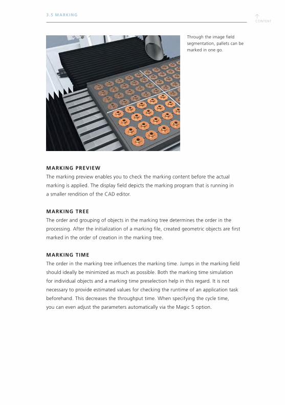
↑CONTENT
3 .5 MARKING
MARKING PREVIEW
The marking preview enables you to check the marking content before the actual
marking is applied. The display field depicts the marking program that is running in
a smaller rendition of the CAD editor.
MARKING TREE
The order and grouping of objects in the marking tree determines the order in the
processing. After the initialization of a marking file, created geometric objects are first
marked in the order of creation in the marking tree.
MARKING TIME
The order in the marking tree influences the marking time. Jumps in the marking field
should ideally be minimized as much as possible. Both the marking time simulation
for individual objects and a marking time preselection help in this regard. It is not
necessary to provide estimated values for checking the runtime of an application task
beforehand. This decreases the throughput time. When specifying the cycle time,
you can even adjust the parameters automatically via the Magic 5 option.
Through the image field
segmentation, pallets can be
marked in one go.
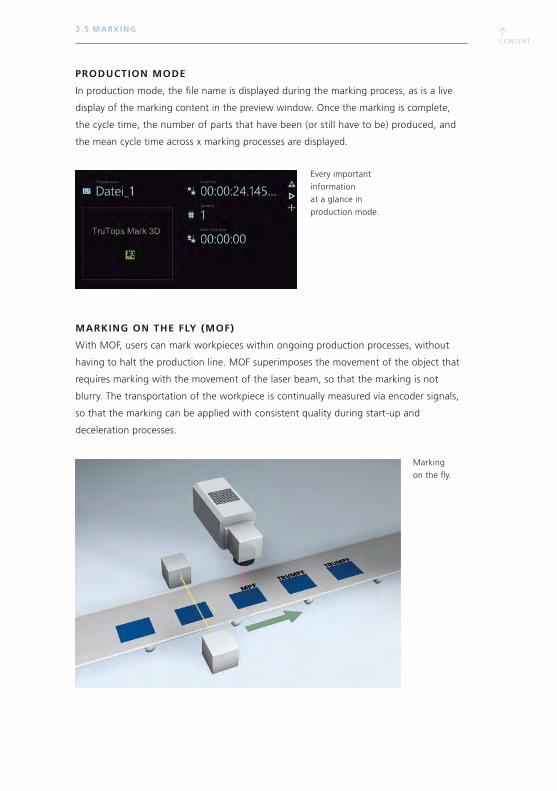
↑CONTENT
↑CONTENT
3 .5 MARKING
PRODUCTION MODE
In production mode, the file name is displayed during the marking process, as is a live
display of the marking content in the preview window. Once the marking is complete,
the cycle time, the number of parts that have been (or still have to be) produced, and
the mean cycle time across x marking processes are displayed.
MARKING ON THE FLY (MOF)
With MOF, users can mark workpieces within ongoing production processes, without
having to halt the production line. MOF superimposes the movement of the object that
requires marking with the movement of the laser beam, so that the marking is not
blurry. The transportation of the workpiece is continually measured via encoder signals,
so that the marking can be applied with consistent quality during start-up and
deceleration processes.
Marking
on the fly.
Every important
information
at a glance in
production mode.
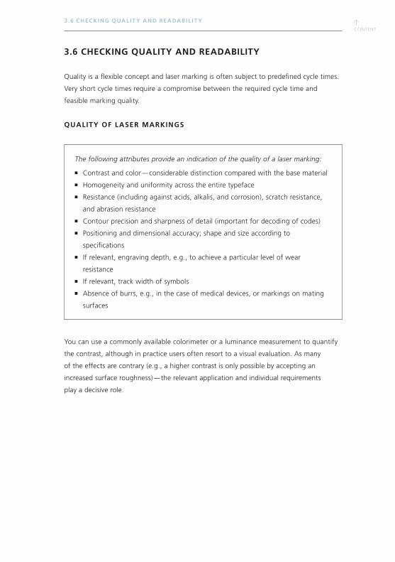
↑CONTENT
3 .6 CHECKING QUAL IT Y AND READABIL IT Y
3.6 CHECKING QUALITY AND READABILITY
Quality is a flexible concept and laser marking is often subject to predefined cycle times.
Very short cycle times require a compromise between the required cycle time and
feasible marking quality.
QUALITY OF LASER MARKINGS
The following attributes provide an indication of the quality of a laser marking:
Contrast and color — considerable distinction compared with the base material
Homogeneity and uniformity across the entire typeface
Resistance (including against acids, alkalis, and corrosion), scratch resistance,
and abrasion resistance
Contour precision and sharpness of detail (important for decoding of codes)
Positioning and dimensional accuracy; shape and size according to
specifications
If relevant, engraving depth, e.g., to achieve a particular level of wear
resistance
If relevant, track width of symbols
Absence of burrs, e.g., in the case of medical devices, or markings on mating
surfaces
You can use a commonly available colorimeter or a luminance measurement to quantify
the contrast, although in practice users often resort to a visual evaluation. As many
of the effects are contrary (e.g., a higher contrast is only possible by accepting an
increased surface roughness) — the relevant application and individual requirements
play a decisive role.
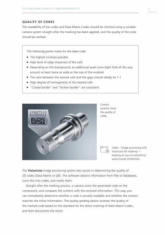
↑CONTENT
↑CONTENT
3 .6 CHECKING QUAL IT Y AND READABIL IT Y
QUALITY OF CODES
The readability of bar codes and Data Matrix Codes should be checked using a suitable
camera system straight after the marking has been applied, and the quality of the code
should be verified.
The following points make for the ideal code:
The highest contrast possible
High level of edge sharpness of the cells
Depending on the background, an additional quiet zone (light field all the way
around, at least twice as wide as the size of the module)
The ratio between the lasered cells and the gaps should ideally be 1:1
High degree of homogeneity of the lasered cells
”Closed border“ and ”broken border“ are consistent
The VisionLine image processing system also assists in determining the quality of
2D codes (Data Matrix or QR). The software obtains information from files or databases,
turns this into codes, and marks them.
Straight after the marking process, a camera scans the generated code on the
component, and compares the content with the received information. This way, you
can immediately determine whether a code is actually readable and whether the content
matches the initial information. The quality grading option assesses the quality of
the marked code based on the standard for the direct marking of Data Matrix Codes,
and then documents the result.
Camera
systems check
the quality of
codes.
Video: “Image processing with
VisionLine for marking — keeping an eye on everything”
www.trumpf.info/ltnhea
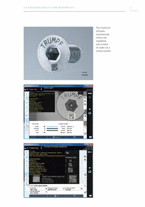
1 mm
↑CONTENT
3 .6 CHECKING QUAL IT Y AND READABIL IT Y
The VisionLine
software
automatically
checks the
readability
and content
of codes via a
camera system.
↑CONTENT
↑CONTENT
3 .7 APPL IC AT ION SUPPORT AND SERVICE
3.7 APPLICATION SUPPORT AND SERVICE
TRUMPF LASER APPLICATION CENTER
Our service starts before users have even decided on a particular laser, as the TRUMPF
application labs located across the globe assist with the decision-making process.
This is where engineers work with the customer to establish processes and equipment,
with the help of prototype components and a requirements catalog. For this, we
carry out tests with lasers from the entire product range, so as to establish the best
combination of marking quality and processing time.
The following are possible in the TRUMPF Laser Application Center:
Full access to the TRUMPF machinery
Tests with all types of lasers
Tests with all focal lengths
Machine demonstrations
Application tests and process development
Checking of processing quality, e.g., the verification of codes
TRUMPF TRAINING COURSES
TRUMPF offers users a variety of different training courses, so that they understand
how to operate their laser in the best way possible. There are training courses for all
qualification levels — from beginner through to seasoned laser users.
Advantages of TRUMPF training courses:
Take a course directly on the machine
Theoretical and practical content — depending on your requirements
Novice through to expert level
Global network of training centers

↑CONTENT
REMOTE SERVICES
With TRUMPF’s monitoring and analysis products, users can maintain an overview of
their equipment and processes at all times. Statuses and processes can be monitored in
real time, thus enabling you to avoid instances of machine and production standstill.
They can also assist in identifying opportunities for improvement that could enable you
to reduce your production times and costs.
GLOBAL SUPPORT
TRUMPF has a global service network that offers everything from installation and
maintenance through to repairs. Many problems can be solved via Remote Diagnostics.
However, in the event of a more serious problem, a service engineer can address it on-site.
3 .7 APPL IC AT ION SUPPORT AND SERVICE

Iden
t-N
o. 2
4934
24_2
0190
6 –
Con
tent
sub
ject
to
chan
ge w
itho
ut n
otic
e
TRUMPF is certified to ISO 9001
(Find out more: www.trumpf.com/s/quality)
TRUMPF Laser- und Systemtechnik GmbHwww.trumpf.com