laser induced aluminum surface breakdown model … laser induced aluminum surface breakdown model...
TRANSCRIPT

ESI-TR-02-06-25
Laser Induced Aluminum Surface Breakdown Model
Final Report
Contract Number: H-33325D
Prepared for
National Aeronautics and Space Administration
George C. Marshall Space Flight CenterMarshall Space Flight Center, AL 35812
by
Y. S. Chen, J. Liu and S. Zhang
Engineering Sciences, Inc.1900 Golf Road, Suite D
Huntsville, AL 35802(256) 883-6233
June 25,2002
https://ntrs.nasa.gov/search.jsp?R=20020058228 2018-06-30T00:49:22+00:00Z
Laser Induced Aluminum Surface Breakdown Model
PROJECT SUMMARY
Laser powered propulsion systems involve complex fluid dynamics,
thermodynamics and radiative transfer processes. Based on an unstructured
grid, pressure-based computational aerothermodynamics platform, several sub-
models describing such underlying physics as laser ray tracing and focusing,
thermal non-equilibrium, plasma radiation and air spark ignition have been
developed. This proposed work shall extend the numerical platform and existing
sub-models to include the aluminum wall surface Inverse Bremsstrahlung (IB)
effect from which surface ablation and free-electron generation can be initiated
without relying on the air spark ignition sub-model. The following tasks will be
performed to accomplish the research objectives.
An aluminum surface ablation-ionization model is developed to provide
surface temperature rise and the generation of seed electron concentration in the
laser focal region that is required for initiate the air breakdown process. A
simplified heat conduction equation is employed to calculate the temperature
evolution of the aluminum surface, which is in tern used for the calculation of
aluminum ionization near the surface.
The coupling of the aluminum surface breakdown model with the
computational fluid dynamics model developed for pulse laser supported
propulsion system allows the simulation to start without the assumption of using
a spark ignition heat source. Benchmark testing of the present model for laser
Lightcraft model-200 has shown the effectiveness of the present model. The
only remaining tunable modeling constant of the present model is in calculating
the effective laser absorption coefficient based on the level of ionization of air
plasma.
INTRODUCTION
Currently, NASA's aim of operating low cost launch and space vehicles
requires the research and development of advanced propulsion technologies and
concepts. One plausible advanced concept is the utilization of off-board pulsed
laser power source to propel small payload (e.g. 100kg) into earth orbit. The
merit of the laser-propelled vehicles is in its high efficiency (do not need to carry
fuel) and high specific impulse. Previous SDIO research led to the invention of
the one of the laser powered launch vehicle concept - the Laser Lightcraft
concept, currently being tested at the High Energy Laser Test System Facility,
White Sands Missile Range, New Mexico. Although the spin-stabilized small
scale Lightcraft model (invented by Myrabo) has been flown successfully up to an
altitude of 30 meters using a 10 kW pulsed-laser at 10 Hz, many technical issues
need to be addressed before an optimized design of the vehicle and its operation
can be achieved.
The purpose of this study is to establish the technical ground for modeling
the physics of laser powered pulse detonation phenomenon. The principle of the
laser power propulsion is that when high-powered laser is focused at a small
area near the surface of a thruster, the intense energy causes the electrical
breakdown of the working fluid (e.g. air) and forming high speed plasma (known
as the inverse Bremsstrahlung, IB, effect). The intense heat and high pressure
created in the plasma consequently causes the surrounding to heat up and
expand until the thrust producing shock waves are formed. This complex
process of gas ionization, increase in radiation absorption and the forming of
plasma and shock waves will be investigated in the development of the present
numerical model. In the first phase of this study, laser light focusing, radiative
absorption and shock wave propagation over the entire pulsed cycle are
modeled. The model geometry and test conditions of known benchmark
experiments such as those in Myrabo's experiment will be employed in the
numerical model validation simulations. The calculated performance data (e.g.
coupling coefficients) will be compared to the test data. Plans for the numerical

modeling of the detailed IB effect will also be described in the proposed
investigation. The final goal will be the design analysis of the full-scale laser
propelled flight vehicle using the present numerical model.
In previous study, Engineering Sciences, Inc. has developed a laser
powered launch vehicle performance analysis tool based on its in-house flow and
radiation codes. UNIC-UNS unstructured-grid flow code and GRADP-UNS
unstructured-grid radiation code are two advanced numerical models. Many
complex engineering design problems related to fluid dynamics and radiative
heat transfer have been solved using these two codes. High-temperature
thermodynamics and plasma dynamics models have been developed with
benchmark data validations presented for laser powered launch vehicles. The
development work has included transient shock capturing algorithm using
unstructured-grid method with dynamic local refinement and coarsening adaptive
grid strategy. High temperature thermodynamics and plasma gas dynamics
physics are modeled and validated. Non-equilibrium radiation model with the
effects of gas breakdown and laser energy absorption has also been addressed
and modeled. These advanced thermodynamics and radiation models serve as
the fundamental building blocks for the present model development and for the
ultimate utilization of the laser powered launch vehicle performance analysis tool
in real designs.
In the present research, the development work for modeling the
mechanisms for initializing the aluminum surface ablation and ionization due to
focused laser energy is completed and tested for a laser Lightcraft model-200.
At the start of the laser pulse, the beams are focused at a small area on the
aluminum surface of the test vehicle. Part of the energy is absorbed by the
material and causes to overcome the bounding energy of the molecules.
According to Harada [1-4], this process is accounted for through stopping power
that is caused by collisions between ions and atoms of the material. Since the
energy source is different in the present application that laser beam instead of
ion beam is the energy source, the energy source modeling would consider the
absorption of radiative energy at the wall surface. In the present case, the energy

absorbed, as output from the radiation model, is used to calculate the heat
conduction and energy balance at the wall surface through which the ablation
rates of the aluminum material from the surface is calculated. The ionization of
the ablated material is then initiated by using the Saha-Eggert equation under the
thermal and chemical equilibrium assumption [4]. The developed model is
described below.
COMPUTATIONAL FLUID DYNAMICS MODEL
Governing Equations
For The Continuity, Navier-Stokes and Energy (Total Enthalpy) Equations,
can be written in a Cartesian tensor form:
)d p + puj = 0 (1)dt
Z( Zlll - _'/V(V2 2) /dt -ff-i-+O_< +Q" +dxs t, P, )
dt -I- _Xj 3 _ e-O_Xj)-t-Qr--Qec
(3)
(4)
where p is the fluid density, u; is the fh Cartesian component of the velocity, p is
the static pressure, _ is the fluid viscosity, Pr is the Prandtl number, H is the gas
total enthalpy and V stands for the sum of velocity squared. In Eqo (4), kb, ne, Te,
2e, Qr, Qv and Qec are the Boltzmann's constant, electron number density,
electron temperature, electron thermal conductivity, radiative heat source from
laser absorption and radiative transfer, vibrational-translation energy transfer
source term, and the energy transfer due to eletron/particle elastic collisions,
respectively. The shear stress z;jcan be expressed as:
5
The species conservation equation is expressed as:
where Yi is the f,h species mass fraction, D is the mass diffusivity, ov is the
turbulent Schmidt number, and (_b, is the chemical reaction rate for species i
respectively.
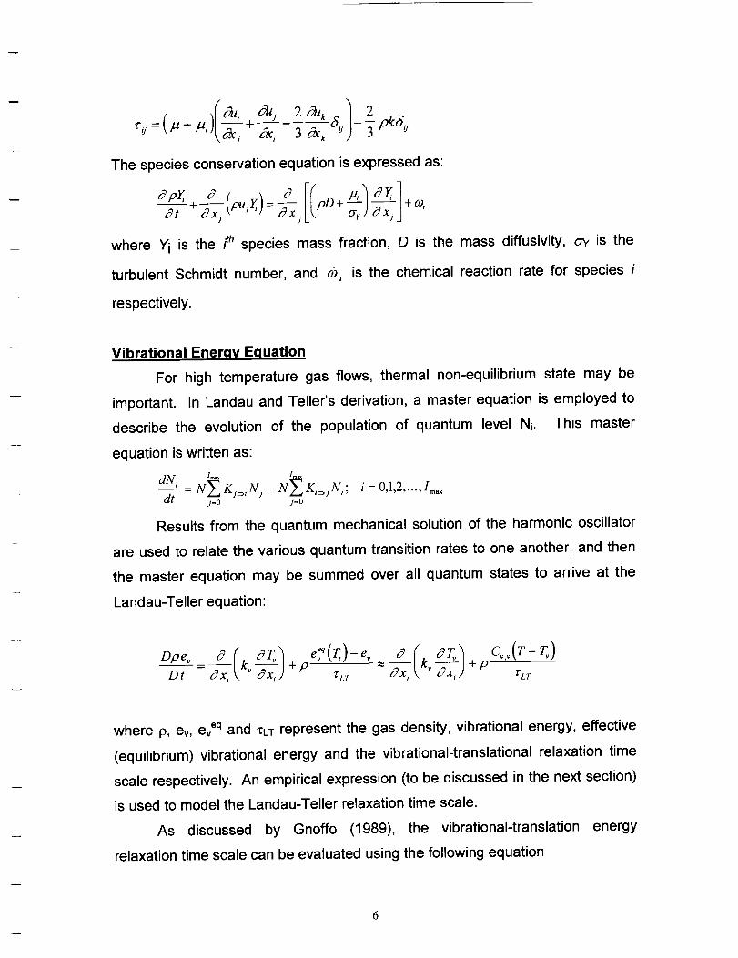
Vibrational Enerqv Equation
For high temperature gas flows, thermal non-equilibrium state may be
important. In Landau and Teller's derivation, a master equation is employed to
describe the evolution of the population of quantum level N_. This master
equation is written as:
dN, N_ K,=,N, - N Z K,=jN,, i 0,1,2 ..... Im_dt j=o j=o
Results from the quantum mechanical solution of the harmonic oscillator
are used to relate the various quantum transition rates to one another, and then
the master equation may be summed over all quantum states to arrive at the
Landau-Teller equation:
Dpe, " I _ toe_q(TI)-e" 0 ( "T_I C,,(T-T,)Dt - c_x, k. 3x,) + rvr ~ Sx, k.-_x,) + p ' rLr
where p, ev, eveq and *Lm represent the gas density, vibrational energy, effective
(equilibrium) vibrational energy and the vibrational-translational relaxation time
scale respectively. An empirical expression (to be discussed in the next section)
is used to model the Landau-Teller relaxation time scale.
As discussed by Gnoffo (1989), the vibrational-translation energy
relaxation time scale can be evaluated using the following equation
6
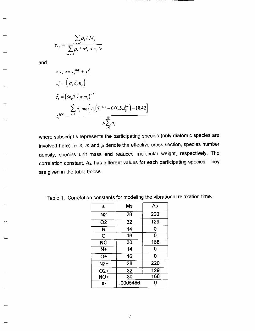
s=mol.
rLr-- _"p, IM, <r,.>s=mol.
and
c_ =(8kbT/ rcm,) ',2
10
'_-_n_ exp[A,(T -''3 -0.015p_:')-18.421
Z- mw _ J=]• lO
p_--_ njJ=l
where subscript s represents the participating species (only diatomic species are
involved here), o;, n, m and fl denote the effective cross section, species number
density, species unit mass and reduced molecular weight, respectively. The
correlation constant, As, has different values for each participating species. They
are given in the table below.
Table 1. Correlation constants for modeling the vibrational relaxation time.
s Ms As
N2 28 220
02 32 129
N 14 0
O 16 0
NO 30 168
N+ 14 0
O+ 16 0
N2+ 28 220
02+ 32 129
NO+ 30 168
e- .0005486 0
7
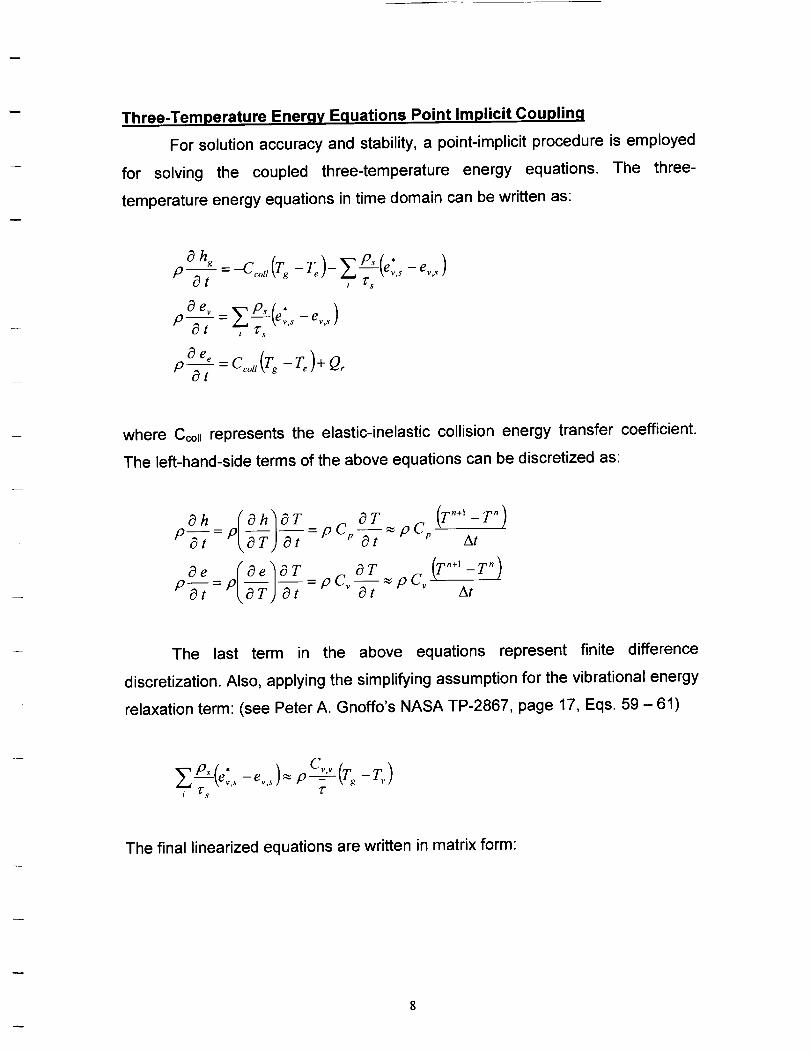
Three-Temperature Enerav Eauations Point Implicit Couplinq
For solution accuracy and stability, a point-implicit procedure is employed
for solving the coupled three-temperature energy equations. The three-
temperature energy equations in time domain can be written as:
__ /__p,(e.,. ,v,-ev )Pat , _s
p--=at
where Cco, represents the elastic-inelastic collision energy transfer coefficient.
The left-hand-side terms of the above equations can be discretized as:
_h (_h_T OT (T"+'-T ")
P_-=P _--__ )-ET=pc_ o--T=pc_ At
The last term in the above equations represent finite difference
discretization. Also, applying the simplifying assumption for the vibrational energy
relaxation term: (see Peter A. Gnoffo's NASA TP-2867, page 17, Eqs. 59 -61)
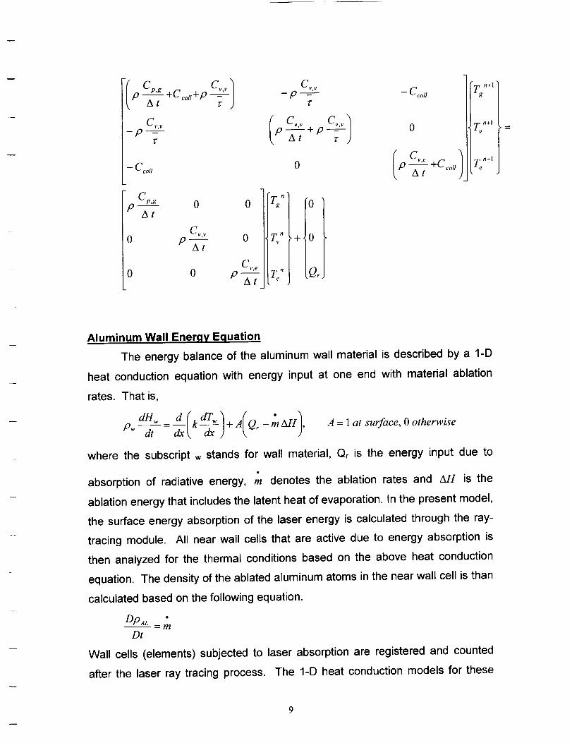
The final linearized equations are written in matrix form:
Ip Cpg Cv.v_-2-;-,_,V
--p_
Z"
-- C coll
Cp,gp-- 0 0
At
C¢,Y
0 p-At
0 0
0
Cv e
p-f-;
Cy,t/
p -T
Ip i..,_+ PAt
0
, o
Iv" .+,0
L" Q, )
-- C coll
0
I Cv,ep
• n+l
Zv n+l
Te n+l
Aluminum Wall Energy Equation
The energy balance of the aluminum wall material is described by a 1-D
heat conduction equation with energy input at one end with material ablation
rates. That is,
A = 1 at surface, 0 otherwise
where the subscript w stands for wall material, Qr is the energy input due to
absorption of radiative energy, m denotes the ablation rates and _sr is the
ablation energy that includes the latent heat of evaporation. In the present model,
the surface energy absorption of the laser energy is calculated through the ray-
tracing module. All near wall cells that are active due to energy absorption is
then analyzed for the thermal conditions based on the above heat conduction
equation. The density of the ablated aluminum atoms in the near wall cell is than
calculated based on the following equation.
DP aL "-m
Dt
Wall cells (elements) subjected to laser absorption are registered and counted
after the laser ray tracing process. The 1-D heat conduction models for these
wall points are solved for the wall surface temperature evolution. The outside
wall is assumed to be always isothermal at 300 K. For simplicity, the aluminum
atom generation is ignored in the present model. It is found that only the
calculation of electron concentration production rate is important for initiating the
air breakdown process.
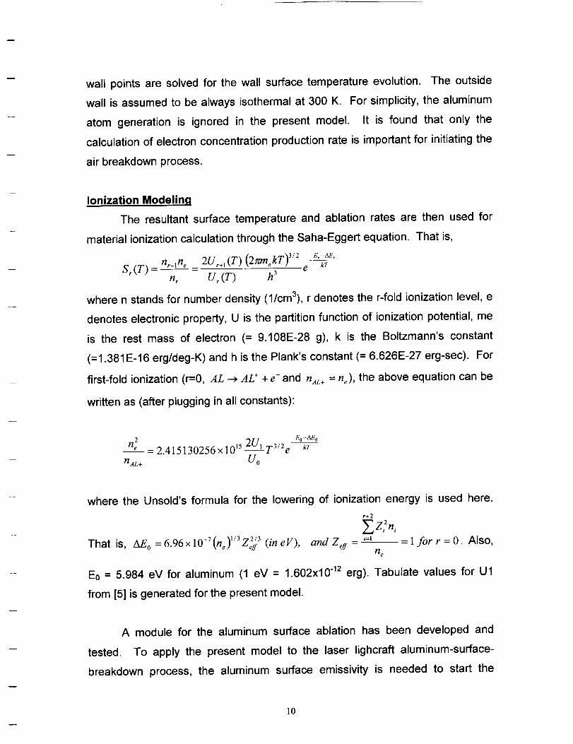
Ionization Modeling
The resultant surface temperature and ablation rates are then used for
material ionization calculation through the Saha-Eggert equation. That is,
Sr(T ) = nr+'ne - 2Ur+'(T) (27zmekT)3/2 e L;-E,nr U_ (T) h 3
where n stands for number density (1/cm3), r denotes the r-fold ionization level, e
denotes electronic property, U is the partition function of ionization potential, me
is the rest mass of electron (= 9.108E-28 g), k is the Boltzmann's constant
(=1.381E-16 erg/deg-K) and h is the Plank's constant (= 6.626E-27 erg-sec). For
first-fold ionization (r=0, AL _ AL + + e-and n,4_ = he), the above equation can be
written as (after plugging in all constants):
n e _ 2.415130256x 1015 "-'l T3/2 eFI AL + Uo
E o- Mi.okT
where the Unsold's formula for the lowering of ionization energy is used here.
That is, AE o = 6.96x 10 -7 (Fie) '/372/3 (in eV),"-'eft
r+2
and Z eff -- _=1
FIe
-- - l for r = O. Also,
E0 = 5.984 eV for aluminum (1 eV = 1.602x10 -12 erg). Tabulate values for Ul
from [5] is generated for the present model.
A module for the aluminum surface ablation has been developed and
tested. To apply the present model to the laser lighcraft aluminum-surface-
breakdown process, the aluminum surface emissivity is needed to start the
10
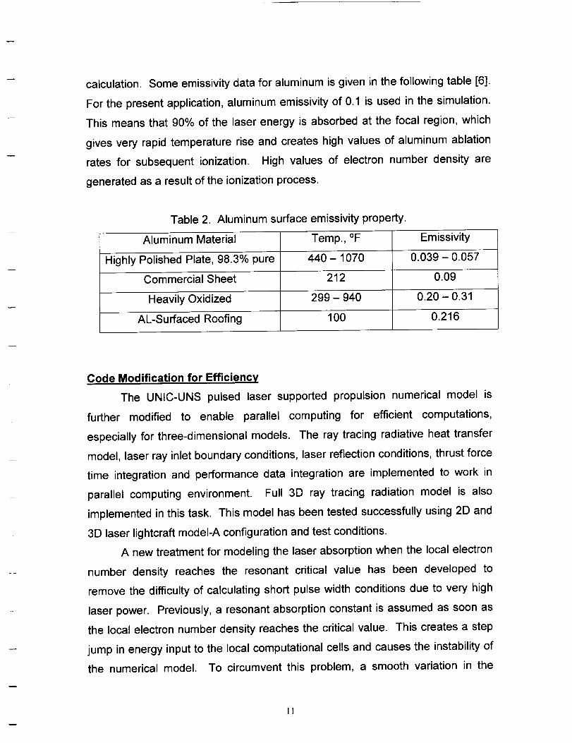
calculation. Some emissivity data for aluminum is given in the following table [6].
For the present application, aluminum emissivity of 0.1 is used in the simulation.
This means that 90% of the laser energy is absorbed at the focal region, which
gives very rapid temperature rise and creates high values of aluminum ablation
rates for subsequent ionization. High values of electron number density are
generated as a result of the ionization process.
Table 2. Aluminum surface emissivity property.
Aluminum Material Temp., °F Emissivity
Highly Polished Plate, 98.3% pure 440 - 1070 0.039 - 0.057
Commercial Sheet 212 0.09
Heavily Oxidized 299 - 940 0.20 - 0.31
AL-Surfaced Roofing 100 0.216
Code Modification for Efficiency
The UNIC-UNS pulsed laser supported propulsion numerical model is
further modified to enable parallel computing for efficient computations,
especially for three-dimensional models. The ray tracing radiative heat transfer
model, laser ray inlet boundary conditions, laser reflection conditions, thrust force
time integration and performance data integration are implemented to work in
parallel computing environment. Full 3D ray tracing radiation model is also
implemented in this task. This model has been tested successfully using 2D and
3D laser lightcraft modeI-A configuration and test conditions.
A new treatment for modeling the laser absorption when the local electron
number density reaches the resonant critical value has been developed to
remove the difficulty of calculating short pulse width conditions due to very high
laser power. Previously, a resonant absorption constant is assumed as soon as
the local electron number density reaches the critical value. This creates a step
jump in energy input to the local computational cells and causes the instability of
the numerical model. To circumvent this problem, a smooth variation in the
!!

energy absorption is assumed before the laser rays reach the plasma resonance
front. This smooth absorption function is constructed based on the electron
number density. Preliminary calculation using this treatment showed increased
integrated thrust coupling coefficients for normal pulse width cases. Test for a
short pulse-width case (with 1 microsecond pulse width) has shown good stability
of the computational model. Fine-tuning of this treatment is necessary to anchor
the modeling constants for its applicability over a selected range of pulse widths
and power levels. Further research is required to test the present model for
Lightcraft performance calculations with short pulse width conditions.
MODEL-200 PERFORMANCE ALANYSlS
The present model is tested for the laser Lightcraft Model-200-3/4 and
compared with experimentally measured data for a range of laser power levels.
Two models are used for comparison purpose. The spark ignition model is used
to provide the baseline of the predictions. Then, the same cases are computed
with the present aluminum-surface breakdown/ionization model. The same laser
absorption model based on a single ionization formula [7] modified by a tabulated
augmentation factor described by Raizer [8] used to simulate multiple ionization
effects.
The impulse thrust of the laser Lightcraft Model-200-3/4 was tested using
a 10 kW CO2 pulse laser, which can provide up to 800J for each single pulse, of
the Pulsed Laser Vulnerability Test System at the High Energy Laser System
Test Facility, White Sands Missle Range, NM. The laser pulse energy was
measured with a calorimeter with an estimated uncertainty of + 10 J in total laser
energy delivered. Several variations of the basic Laser Lightcraft design (Model-
200 series) similar to those described in Ref. 9 and 10 were tested
experimentally. The test results of the 6061-T6 all aluminum Model #200-3/4
vehicle with 18 ps pulse width [10] are chosen for this study. The impulse
measurements were conducted with a pendulum apparatus, which has an
estimated impulse measurement uncertainty of 1% or better [9,10].
12

A hybrid unstructured mesh system, shown in figure 1, was generated for
the present computation. Also shown, as yellow spots, in figure 1 are the laser
traces from the downstream side of the vehicle. Figure 2 shows a close-up view
in the cowl region that reveals the hybrid grid arrangement. The element and
node numbers for this grid are 26,142 and 14,441 respectively. For spark
ignition model, 25% of laser power is assumed as the initial heat source near the
focal region. The spark heat source region is bounded by the laser traces and a
radius of 1.355 mm from the focal point of the parabolic optical surface of the
vehicle. The spark heat source is turned off when the air plasma reaches the
self-sustain state (specified as when laser energy absorption efficiency reaches
15%).
8
6
4
2
>. 0
-2
-4
-6
-8
Figure 1.
-5 0 5X
Mesh system and laser traces for the Model-200-3/4 laser Lightcraft.
13

For the present model, the spark ignition model is totally eliminated. The
aluminum surface breakdown/ionization model replaces the air plasma initiation
process. Assuming that the aluminum surface emissivity of 0.1, 90 percent of the
laser energy is therefore used for the heat-up and breakdown of the aluminum
near the focal region. One-dimensional heat conduction equation for the
aluminum wall segments, where laser energy absorption is registered, is solved
for the time history of the aluminum surface conditions. Surface breakdown and
ionization process is then calculated based on the aluminum surface conditions.
This provides the electron species production rate in the near wall region, which
is responsible for initiating the air plasma. As a result of this model, the surface
heat-up time and ionization time scale is directly proportional to the input laser
power and the focus condition of laser beam (i.e. better focus produces faster
heat-up and plasma iginition).
>..
5.5
5
4.5
4
3.50 0.5 1 1.5 2
X
Figure 2. Close-up view of the grid in the cowl region.
]4
\
In the numerical computations, the initial time step size is specifed at 0.05
microseconds and linearly increased to 1 microsecond between 50 to 500
microseconds. This arrangement allow better time resolution for accuracy at the
start-up due to expected fast temperature and pressure rise near the focal region
and allow better computing time as the blast wave expands and its strength
weakened. During every time marching step, the point implicit chemistry solution
procedure and the three-temperature coupled equations are solved with reduced
time step size based on the chemistry time scale. This multiple time stepping for
chemistry is realized to provide the time accuracy for the species equations and
has shown great improvement in the smoothness of the flowfield.
During the course of performing the computations, it was found that the
pressure and velocity fields near the axis had developed spurious oscillations as
the solution proceeded beyond 100 microseconds. The source of this anomaly
was traced to be stemming from the cumulative round-off errors in computational
cell volume and area calculations. This error becomes obvious for transient flow
with quiescent freestream conditions, which is the case for the present
application. A better-structured pressure-smoothing scheme is therefore
introduced to damp out these background oscillations. Further test of the new
scheme has shown good results.
The flowfield solution plots of density, pressure, Mach number, heavy gas
temperature, vibrational temperature and electron temperature, for the 400J case
at 10 microseconds time level are shown in Figure 3. The laser traces are also
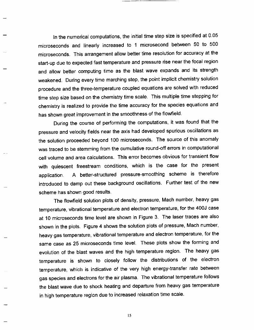
shown in the plots. Figure 4 shows the solution plots of pressure, Mach number,
heavy gas temperature, vibrational temperature and electron temperature, for the
same case as 25 microseconds time level. These plots show the forming and
evolution of the blast waves and the high temperature region. The heavy gas
temperature is shown to closely follow the distributions of the electron
temperature, which is indicative of the very high energy-transfer rate between
gas species and electrons for the air plasma. The vibrational temperature follows
the blast wave due to shock heating and departure from heavy gas temperature
in high temperature region due to increased relaxation time scale.
15

7
6
5
4
3
2
1>-
0
-1
-2
-3
-4
-5
-6
7
6
5
4
3
2
1
0
-1
-2
-3
-4
-5
-6
>.
-7 -6 -5 -4 -3 -2 -1 0 1 2 3 4 5 6 7X
(a) Density, kg/m 3
-7-6 -5 .4 -3 -2-1 0 1 2 3 4 5 6 7X
(b) Pressure, ATM
Figure 3. Flowfield solution for 400 J laser energy case at 10 i_sec.
]6

>-
>.
7
6
5
4
3
2
1
0
-1
-2
-3
-4
-5
-6
7
6
5
4
3
2
1
0
-1
-2
-3
-4
-5
-6
-7 -6 -5 -4 -3 -2-1 0 1 2 3 4 5 6 7X
(c) Mach Number
-7 -6 -5 -4 -3 -2 -1 0 1 2 3 4 5 6 7X
(d) Heavy Gas Temperature, K
Figure 3. (Continued) Flowfield solution for 400 J laser energy case at 10 psec.
]7

)-
>.
7
6
5
4
3
2
1
0
-1
-2
-3
4
-5
-6
7
6
5
4
3
2
1
0
-1
-2
-3
-4
-5
-6
-7 -6 -5 -4 -3 -2 -1 0 1 2 3 4 5 6 7X
(e) Vibrational Temperature, K
-7 -6 -5 -4 -3 -2 -1 0 1 2 3 4 5 6 7X
(f) Electron Temperature, K
Figure 3. (Concluded) Flowfield solution for 400 J laser energy case at 10 _sec.
18

At the beginning, as the shock wave develops, negative thrust is produced
due to the shape of cowl inner surface. Later, the shock wave hits the upstream
corner of the cavity. As indicated in Figure 4 (a), the pressure level is increased
to 41 ATM due to shock reflection off the upstream corner in the cavity. The
high-pressure region is attached to the parabolic optical surface. During this time
period for the high-pressure wave to travel along the optical surface, the positive
thrust is produced and can be referred to as thrust-producing period. As the
shock wave expands to wrap around the cowl outer surface and leaves the tip of
the optical surface, negative contribution to the thrust will resume until the thrust
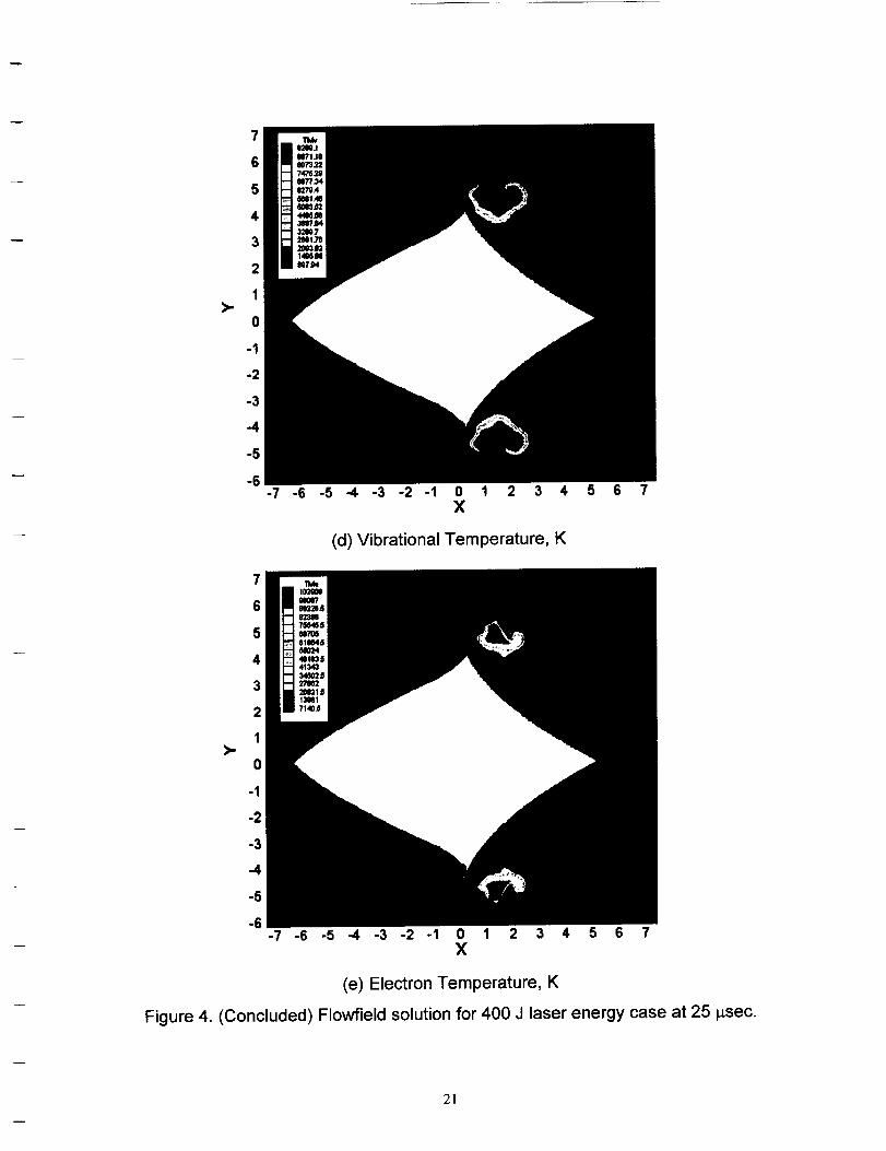
curve levels off. The evolution of the time-integrated thrust curves for different
power levels of the laser is shown in Figure 5 for the present model using
aluminum surface breakdown model to initiate the air plasma. The final vehicle
thrust coefficients (expressed as coupling coefficient) are then recorded based
on the level-off thrust curves and used for data comparisons.
>-
7
6
5
4
3
2
1
0
-1
-2
-3
-4
-5
-6
P40,9719
3e2077
3_A_3P
329404 Aiu
24Jl27 _;) _ " Lnl
10_-_z .,,_y% /-/15W40 _ "% _ j
e_12 / \
hJJJlJJJJlJJJJlJJJllllllltl]tl]llllll]Jh Jl]llltlhlltlJllllll_lllllllll
-" -6 -5 -4 -3 -2-1 0 1 2 3 4 5 6 7X
(a) Pressure, ATM
Figure 4. Flowfield solution for 400 J laser energy case at 25 i_sec.
]9

>.
>.
7
6
5
4
3
2
1
0
-1
-2
-3
-4
-5
-6
7
6
5
4
3
2
1
0
-1
-2
-3
-4
-5
-6
-7-6 -5 -4 -3 -2-1 0 1 2 3 4 5 6 7X
(b) Mach Number
-7-6 -5 -4 -3 -2-1 0 1 2 3 4 5 6 7X
(c) Heavy Gas Temperature, K
Figure 4. (continued) Flowfield solution for 400 J laser energy case at 25 psec.
2o
>.
7
6
5
4
3
2
1
0
-1
-2
-3
-4
-5
-6
7
6
5
4
3
2
1
0
-1
-2
-3
-4
-5
-6
-7 -6 -5 -4 -3 -2 -1 0 1 2 3 4 5 6 7X
(d) Vibrational Temperature, K
-7 -6 -5 -4 -3 -2 -1 0 1 2 3 4 5 6 7X
(e) Electron Temperature, K
Figure 4. (Concluded) Flowfield solution for 400 J laser energy case at 25 t_sec.
21
22 _-_ J075
20 _ J200_ ,1300
ltlOO
Zm
..IG.:DOO
12
10
8
6
4
2
0
-2
0 0.001 0.002 0.003 0.004
TIM E (sec)
Figure 5. Integrated coupling coefficient time history for different laser input
energy of 75J, 200J, 300J and 400J.
The predicted coupling coefficients for the 75J, 200J, 300J and 400J
cases are 2.03, 12.7, 14.6 and 15.21 respectively with the present model. These
results are consistently lower than the predicted values of the previous model
using the spark ignition mechanism. This is understandable since the laser
absorption coefficient was tuned for the spark ignition model. Further tuning of
the absorption coefficient is needed to fit the present model predictions to the
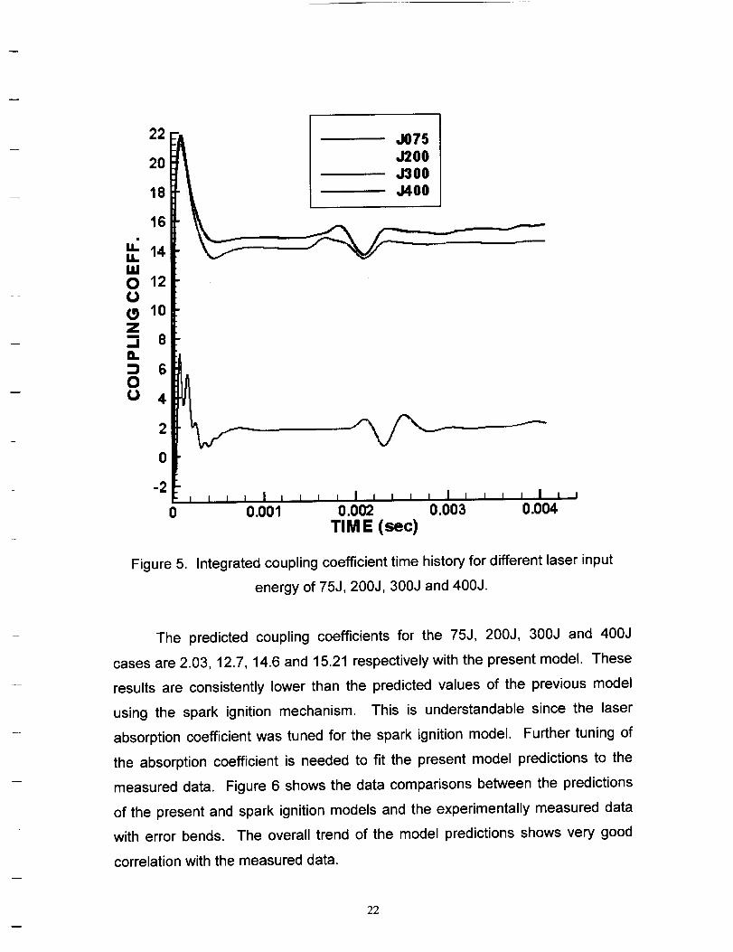
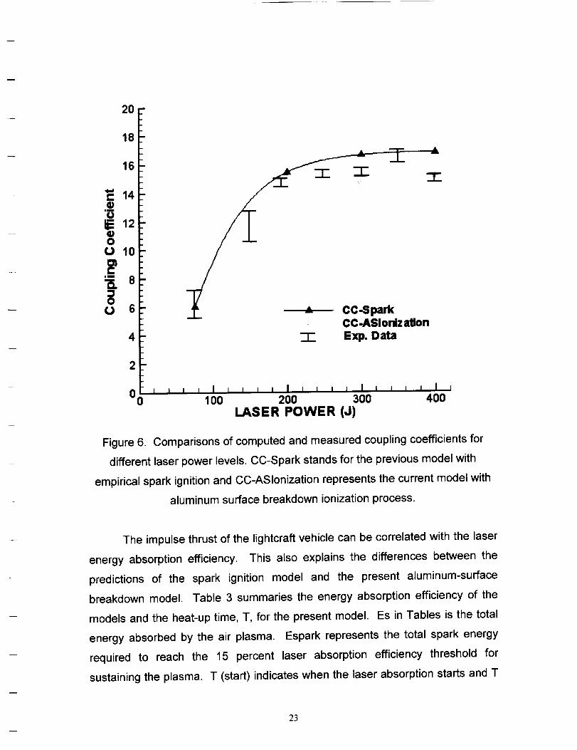
measured data. Figure 6 shows the data comparisons between the predictions
of the present and spark ignition models and the experimentally measured data
with error bends. The overall trend of the model predictions shows very good
correlation with the measured data.
22
20-
18
16
14
1210
4
2
0 0 ' ,
-" CC.SparkCC-ASIoniz ation
-I- Exp. Data
100 200 300 400
LASER POWER (J)
Figure 6. Comparisons of computed and measured coupling coefficients for
different laser power levels. CC-Spark stands for the previous model with
empirical spark ignition and CC-ASIonization represents the current model with
aluminum surface breakdown ionization process.
The impulse thrust of the lightcraft vehicle can be correlated with the laser
energy absorption efficiency. This also explains the differences between the
predictions of the spark ignition model and the present aluminum-surface
breakdown model. Table 3 summaries the energy absorption efficiency of the
models and the heat-up time, T, for the present model. Es in Tables is the total
energy absorbed by the air plasma. Espark represents the total spark energy
required to reach the 15 percent laser absorption efficiency threshold for
sustaining the plasma. T (start) indicates when the laser absorption starts and T
23
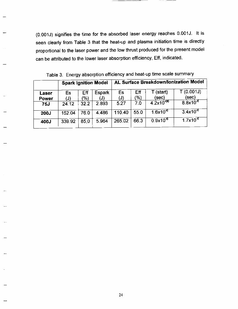
(0.001J) signifies the time for the absorbed laser energy reaches 0.001J. It is
seen clearly from Table 3 that the heat-up and plasma initiation time is directly
proportional to the laser power and the low thrust produced for the present model
can be attributed to the lower laser absorption efficiency, Eft, indicated.
Table 3. Energy absorption efficiency and heat-up time scale summary
Spark Ignition Model
Laser Es
Power (J)75J 24.12
200J 152.04
400J 339.92
Eft
(%)32.2
76.0
85,0
AL Surface Breakdown/Ionization Model
Espark Es(J) . (J)
2.893 5.27
4.486 110.40
5.964 265.02
Eft T (start)(%) (sec)7.0 4.2x10 -°6
55.0 1.6x10 .6
66.3 0.9x10 .6
T (0.001J)(sec)
8.8x10 e
3.4xl 0.6
1.7x10 -6
24

CONCLUSIONS
In the present study, an aluminum surface breakdown/ionization model
has been developed and tested for a laser Lightcraft launch vehicle design. The
aluminum surface temperature rise due to laser energy input has been modeled
using a one-dimensional heat conduction equation with laser radiation heat
source applied on the wall surface. An averaged emissivity of 0.1 is assumed for
the aluminum surface. The subsequent ionization process near the aluminum
surface is calculated based on the wall surface conditions obtained for every time
step. This provides the needed electron generation source term near the laser
focal region to initiate the air plasma and the associated blast waves. The
present model has been demonstrated to replace the need for an artificial spark
ignition mechanism as used in the previous model. Hence, this research has
provided one step further in making the present analytical model as a true
predictive tool for laser supported propulsion system with reduced empiricism.
Benchmark testing of the laser Lightcraft Model-200-3/4 has demonstrated
the effectiveness of the present model in predicting the integrated coupling
coefficient of the vehicle. The predicted trend is in good agreement with the
previous model and the measured data. Further tuning of the modeling
constants in estimating the laser absorption coefficient is needed to really fit the
present predictions with the measured data. The current development work has
laid a concrete foundation for future research in advanced propulsion concepts
that may involve short pulses of high intensity energy sources such as
microwave, electromagnetism, etc.
25

REFERENCES
1. Harada, Nob., Kagihiro, M., Shinkai, H., Jiang, W. and Yatsui, K., "Flyer
Acceleration by Ablation Plasma Using an Intense Pulsed Ion Beam," AIAA
99-3485, 30 th Plasmadynamics and Lasers Conference, 28 June - 1 July,
1999, Norfolk, VA.
2. Harada, Nob., Yazawa, M., Kashine, K., Jiang, W. and Yatsui, K., "Numerical
Simulation of Foil Acceleration by Intense Pulsed Ion Beam," AIAA 2000-
2272, 31 stAIAA Plasmadynamics and Lasers Conference, 19-22 June, 2000,
Denver, CO.
3. Harada, Nob., "Acceleration of Multi-Layer Foil by Intense Pulsed Ion Beam,"
AIAA 2001-3005, 32 nu AIAA Plasmadynamics and Lasers Conference, 11-14
June, 2001, Anaheim, CA.
4. Harada, Nob., (Private Communication), September, 2001.
5. Drawin, Hans-Werner and Felenbok, Paul, Data for Plasmas in Local
Thermodynamic Equilibrium, Gauthier-Villars, Editeur, Paris, 1965.
6. Reynolds, William C., and Perkins, Henry C., En.qineerin.q Thermodynamics,
McGraw-Hill Book Company, New York, NY, 1970.
7. Raizer, Y.P., and Tybulewicz, A., "Laser-Induced Discharge Phenomena",
.
.
10.
Studies in Soviet Science, Edited by Vlases, G.C., and Pietrzyk, Z.A.,
Consultants Bureau, New York, 1977.
Zel'dovich, Y.B., and Raizer, Y.P., "Physics of Shock Waves and High
Temperature Hydrodynamic Phenomena", Vol. 1, Edited by Hayes, W.D., and
Probstein, R.F., Academic Press, New York and London, 1966.
Myrabo, L.N., Messitt, D.G., and Mead, F.B., Jr., "Ground and Flight Tests of
a Laser Propelled Vehicle," AIAA Paper 98-1001, Jan., 1998.
Mead, F.B., Jr., and Myrabo, L.N., Messitt, D.G., "Flight and Ground Tests of
a Laser-Boosted Vehicle," AIAA Paper 98-3735, July, 1998.
26

1. ^GENCYUSEONLY_ _) _. REPORTOATE & REPORTTYPEN_ODATES_:)VEREOJune 2512002 Final Report
4. TITLEN_ SUBTm.ELaser Induced Aluminum Surface Breakdown Model
e. mJTHOa(S)Yen-Sen Chen, Jiwen Liu and Sijun Zhang
7. pF.aFOgmlNO_TION I_=(S) N_ON)ORESS(SS)
Engineering Sciences, Inc.1900 Golf Road, Suite D, Huntsville, AL 35802
9. SPONSORING_WX_iTO_AGENCYNAME(S)ANDADDRESS(F.S)
George C. Marshall Space Flight CenterMarshall Space Flight Center, AL 35812
5. FUNDINGNUMBERS
H-33325D
8. PERFORMING_TONREPORTNUMBERS
10. _NGAGENCY REPORT NUMBER
11. SUPPLEMENTARY NOTES
Ten-See Wang / Technical Monitor
121. DISTRIBUTION/AVAILABILITY STATEMENT 12b. DISTRIBUTION COOE
13. ABSTRACT(Maxmmn200wonal
Laser powered propulsion systems involve complex fluid dynamics, thermodynamics and
radiative transfer processes. Based on an unstructured grid, pressure-based computational
aerothermodynamics platform, several sub-m:Odels describing such underlying physics as
laser ray tracing and focusing, thermal non-equilibrium, plasma radiation and air spark
ignition have been developed. This proposed work shall extend the numerical platform and
existing sub-models to include thealuminum wall surface Inverse Bremsstrahlung (IB) effect
from which surface ablation and free-electron generation can be initiated without relying on
the air spark ignition sub-model. The following tasks will be performed to accomplish the
research objectives.
14. SUBJECTTERMS
Laser Propulsion Analysis, Aluminum Surface Breakdown, Ionization Modeling
17. SECURITYCLASSIFICATION18. SECURITYCLASSIFICATION19. SECURITYCLASSIFICATION," OFTHISPAGE OFABSTRACT
Unclassified Unclassified Unclassified
NSN 7540 - 01 - 280 - 5500
IS. NUMBER OF PAGES
7,716. PRICE COOE
Hac-C.omputet Oenerated
20. LIMITATION OF ABSTRACT
Unlimited
swmHI Fon_2M (Raw24M))P_ byN_I_S_L23_-1e
27