laser ignition application in a space experiment · laser ignition application in a space...
TRANSCRIPT

NASA Technical Memorandum 106133 .7./f
Laser Ignition Application in a Space Experiment
Larry C. Liou and Dennis E. Culley
Lewis Research Center
Cleveland, Ohio
Prepared for the
OE/LASE '93 Conference
sponsored by the Society of Photo-Optical Instrumentation Engineers -
Hilton/Airport Marriott
Los Angeles, California, January 19-20, 1993
I IASA
(NASA-TM- i06133) LASER IGNITION
APPLICATION _N A SPACE EXPERIMENT
(NASA) 15 p
G3/29
N93-25337
Uncles
0160257
https://ntrs.nasa.gov/search.jsp?R=19930016148 2018-08-19T21:20:39+00:00Z

Laser ignition application in a space experiment
Larry C. Liou
Dennis E. Culley
NASA Lewis Research Center
21000 Brookpark RoadCleveland, Ohio 44135
ABSTRACT
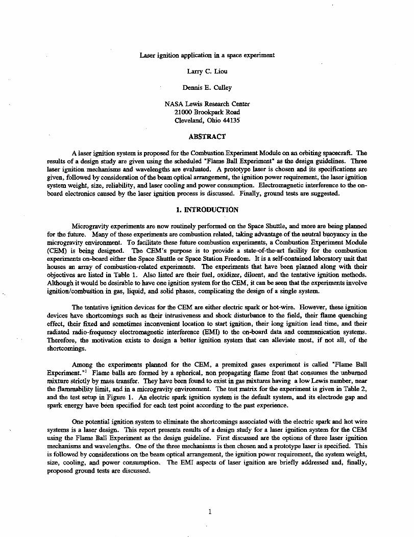
A laser ignition system is proposed for the Combustion Experiment Module on an orbiting spacecraft. The
results of a design study are given using the scheduled "Flame Ball Experiment" as the design guidelines. Three
laser ignition mechanisms and wavelengths are evaluated. A prototype laser is chosen and its specifications are
given, followed by consideration of the beam optical arrangement, the ignition power requirement, the laser ignition
system weight, size, reliability, and laser cooling and power consumption. Electromagnetic interference to the on-
board electronics caused by the laser ignition process is discussed. Finally, ground tests are suggested.
1. INTRODUCTION
Microgravity experiments are now routinely performed on the Space Shuttle, andmore are being planned
for the future. Many of these experiments are combustion related, taking advantage of the neutral buoyancy in the
microgravity environment. To facilitate these future combustion experiments, a Combustion Experiment Module
(CEM) is being designed. The CEM's purpose is to provide a state-of-the-art facility for the combustionexperiments on-board either the Space Shuttle or Space Station Freedom. It is a self-contained laboratory unit that
houses an array of combustion-related experiments. The experiments that have been planned along with their
objectives are listed in Table 1. Also listed are their fuel, oxidizer, diluent, and the tentative ignition methods.
Although it would be desirable to have one ignition system for the CEM, it can be seen that the experiments involve
ignition/combustion in gas, liquid, and solid phases, complicating the design of a single system.
The tentative ignition devices for the CEM are either electric spark or hot-wire. However, these ignition
devices have shortcomings such as their intrusiveness and shock disturbance to the field, their flame quenching
effect, their fixed and sometimes inconvenient location to start ignition, their long ignition lead time, and their
radiated radio-frequency electromagnetic interference (EMI) to the on-board data and communication systems.
Therefore, the motivation exists to design a better ignition system that can alleviate most, if not all, of the
shortcomings.
Among the experiments planned for the CEM, a premixed gases experiment is called "Flame Ball
Experiment. "1 Flame balls are formed by a spherical, non propagating flame front that consumes the unburned
mixture strictly by mass transfer. They have been found to exist in gas mixtures having a low Lewis number, near
the flammability limit, and in a mierogravity environment. The test matrix for the experiment is given in Table 2,
and the test setup in Figure 1. An electric spark ignition system is the default system, and its electrode gap and
spark energy have been specified for each test point according to the past experience.
One potential ignition system to eliminate the shortcomings associated with the electric spark and hot wire
systems is a laser design. This report presents results of a design study for a laser ignition system for the CEM
using the Flame Ball Experiment as the design guideline. First discussed are the options of three laser ignition
mechanisms and wavelengths. One of the three mechanisms is then chosen and a prototype laser is specified. This
is followed by considerations on the beam optical arrangement, the ignition power requirement, the system weight,
size, cooling, and power consumption. The EMI aspects of laser ignition are briefly addressed and, finally,
proposed ground tests are discussed.

2. LASER IGNITION MECHANISM OPTIONS
There are three mechanisms for laser ignition: (1) photochemical, (2) thermal ignition, and (3) Laser
Induced Spark (LIS). In photochemical ignition, laser photons dissociate the target molecules into highly reactive
radical species. These radicals then initiate the rapid chemical chain reaction, or combustion. Photochemical
ignition requires a close match between the laser excitation wavelength and the target molecule's absorption
wavelength in order for dissociation to occur. Only radiation of sufficient energy at these matching (resonant)
wavelengths can bring about dissociation and start the combustion successfully and efficiently. For example, to
dissociate oxygen molecules, 02, wavelength of 157 nm (F laser line) or 193 nm (ArF laser line) can be used.
Photochemical ignition requires only a small amount laser energy, typically less than a millijoule for O2/I-I2and some
02 and hydrocarbon mixtures. TM In comparison with other ignition mechanisms, photochemical ignition can be used
to ignite mixtures at lower pressure and closer to the flammability limits, so long as a sufficient amount of reactive
radicals can be generated from the target molecules. Unfortunately, however, photochemical ignition requires
energetic laser photons, usually at a wavelength of less than 700 nm, where compact and light weight diode lasers
for flight applications are not available.
The second mechanism, thermal ignition, 5 uses a laser beam to increase the kinetic energy, in either
translational, rational, or vibrational form, of the target molecules. As a result, the molecular bonds are eventually
broken and chemical reactions take place. The ignition delay time is typically longer compared to the other two
laser ignition mechanisms, and close matching between the laser wavelength and the target molecule's absorptionwavelength is needed. This mechanism is unique in that it can easily be used to ignite combustibles in combination
of solid, liquid, and gas phases. However, heating of the material is mostly done with infrared lasers, and not allof these lasers are available for flight applications.
In LIS ignition, a laser beam is focused to create a plasma kernel, or spark, via either multiphotonabsorption, or the inverse bremstrahlung process. 6 This spark emits light, heat, and a shock wave to the surrounding
medium, supplying energy to initiate combustion. LIS ignition is mainly a thermal chemical process in which the
heat generated in both the laser spark and the emanating shock wave is responsible for ignition. To produce sparks
for ignition, laser beams are typically pulsed at a Q-switch pulse duration of ~10 nanoseconds, and focused, to
provide the high power density (W/cm 2) required. Infrared (10.6/zm) and near infrared (1.06/zm) are only two
of the many wavelengths that have been used to ignite 02/H 2 and hydrocarbon mixtures. LIS ignition is less
selective in its laser wavelength than the other two mechanisms. In fact, so long as this laser power density, or
irradiance, at the focus is sufficiently high to generate heat for ignition, it matters little what laser wavelength is
used. This could be a major convenience when applying this ignition concept in a flight experiment, since powerful
pocket-sized infrared diode lasers, weighing just a few pounds, are now widely available. LIS ignition has mostly
been applied to ignite gaseous mixtures, although in one instance it was used successfully to ignite liquid fuel. 7 One
shortcoming of Lis however, is that it tends to generate shock waves in gaseous mixtures and eject particles from
liquids and solids, which may interfere with the experiment.
As mentioned before, it would be desirable to have a single laser ignition mechanism/system for the entire
matrix of experiments planned for the CEM. Because of the reasons described above, LIS ignition is probably not
appropriate for solid fuel ignition which two of the CEM experiments require. But photochemical and thermal
ignition remain to be candidates for the CEM single laser ignition system sought after. However, for either concept,more research still needs to be done to identify the optimal laser wavelength to use. In the event that one optimal
wavelength is not possible, a laser with a widely tunable wavelength has to be used. At the present state of the art,
the ability to build such a widely tunable laser suitable for a space mission is questionable.
2

Consideringtheignitionsystemonlyforthe Flame Ball Experiment, the photochemical ignition mechanismis the best theoretical choice because of its ability to ignite near-limit, low pressure, low temperature, gaseous
mixtures. However, a UV laser for flight is not commercially available currently. Therefore, LIS ignition is
recommended for the Flame Ball Experiment. It is believed that LIS is capable of ignition at all of the test pointsof the Flame Ball Experiment because of its similarities to electric sparks, which have achieved ignition at these
conditions. Furthermore, reliable, compact, light weight, and low-cost near infrared lasers are commercially
available for LIS generation. A prototype near-infrared laser comparable to a commercial model has been adopted
for this design effort and is described in the following section.
3. DESIGN CONSIDERATIONS
In this section, some design aspects of an LIS ignition system for the Flame Ball Experiment are
considered. First, a prototype laser is specified for the system. Then, based on this laser, a beam path arrangement
is proposed, followed by the laser ignition energy estimate and considerations related to the weight, size, power
consumption, and cooling of the laser ignition system. Finally, the potential EMI radiated by the system isdiscussed.
3.1. Specifications for the selected laser system
The prototype ignition system laser configuration is described below:
Wavelength:
Energy per Pulse:Pulse Duration:
Beam Diameter:
laser Head Dimension:
Power Supply Dimension:
Nominal Weight:
Power Consumption:
Cooling Requirement:
1064 um
2O0 mJ
10 ns
6mm
28 cm (L) x 5 cm (W) x 5 cm (H)
25 cm (L) x 10 cm (W) x 8 cm (H)
4.5 Kg
20 W (Average) at 28 VDCAIR
These specifications have been selected based on commercial availability.
3.2. Beam path optical arrangement
Given the laser specifications, one possible physical arrangement of the laser and optics relative to the
combustion chamber is shown in Figure 2. The laser and optics unit can be conveniently attached to the test
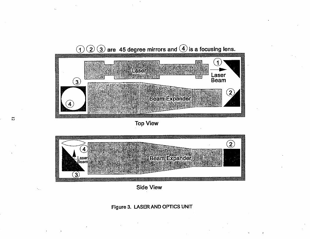
chamber with its beam entering the chamber via an optical window. The laser and optics unit is shown in greater
detail in Figure 3. In this design, the laser beam is turned 3 times by the three mirrors, first expanded by a beam
expander and then focused into the test chamber. The multiple turns of the beam allow for a compact laser and
optics unit design. Of course, many other possibilities of arranging the beam path also exist. Note that, in the
arrangement shown, the beam is expanded in order to provide a smaller focal spot. A small focal spot is needed
to attain a laser power density high enough to create laser sparks.
3.3. Ignition energy/power
Given the prototype laser and optics unit, it should be considered whether the laser beam power is sufficient
for igniting the mixtures in the Flame Ball Experiment. Presently, there is no general model available for predicting
the energy requirement in laser ignition. However, it has been shown in the past that the amount of laser energy
required for ignition is comparable to the electric spark ignition, s The electric spark ignition energy requirement
for the Flame Ball Experiment has been given in Table 2. From the table we can see that the maximum value is
lO0 mJ. Taking this into account, all that is required is that the LIS ignition system provides at least the same
amount of energy, E=_= lO0 mJ, at the spark location as the electric spark system does. Furthermore, we need to

makesurethatthelaserbeampowerdensity(W/cm2)at the focus is high enough to create a breakdown in the gas
and create sparks. The breakdown threshold has been recorded for many gases in the past. 9 A nominal value of
= 1.0 x 10 H W/cm 2 will be used here.
The calculation given below shows that the prototype laser ignition system provides sufficient energy ( >
E_ ) and power ( > I_. ) for the Flame Ball Experiment. The calculation uses 200 mJ of laser pulse energy with
a pulse duration of l0 nsec and a laser wavelength of 1.06/_m. Other input values are: expanded beam diameterof 1.8 cm, a focal length of 25.4 cm, and an worst-ease, 8% average energy loss on each of the seven optical
elements in the laser beam path due to absorption and reflection.
E/ea, 1-ai)(1-a2)(1-a.s)...
'_Vhere Eft=laser energy at the focus
E_= laser output = 200 mJ
a, a2,a3...a5= loss factor = 0.08
Afco_e =- area of the focal spot
Dfo_= diameter of the focal spot
D_= expanded beam diameter = 1.8 cmf= focal length = 25.4 cm
_= laser wavelength = 1.06/tm
If_-- area power density, or irradiance
t_= laser pulse duration = 10 nsec.
E_=118mJ>Effija= 100mJ
lf_s=4 × l Ol2W/cm 2>lffi_ = l × l Oll W]cm 2
As mentioned previously, laser ignition requires roughly the same amount of energy as the conventional
electric spark systems. This fact can be used for estimating purposes, but in order to find the accurate amount of
laser energy required under specific conditions, actual tests are necessary. After all, LIS ignition is quite different
from electric sparks. In LIS ignition, the energy is deposited in a smaller volume in a shorter period of time. A
laser pulse (typically 10 ns) is 1000 times shorter than the discharge duration of electric sparks. These differences
enhance ignition, but also produce opposite effects. They enhance ignition because their small volume for energy
deposition decreases the surface heat loss, and their short energy deposition duration enables a higher peak
temperature for activating the chemical reaction, while allowing less time for heat loss. But, if laser sparks are too
small, the surface contact area becomes too small for sufficient energy transfer to the surrounding unreacted
molecules for ignition. Plus, if the temperature is overly high, the radiation heat loss becomes excessive. Energy
loss can also occur in the strong point-source blast wave generated by a tightly focused laser beam.
4

3.4. Weight, size, power consumption, and cooling
The LIS ignition system is appropriate for the Flame Ball Experiment partly because of the following
practical reasons: The total weight (4.5 kilograms for laser systems plus 0.5 kilograms for optics unit) and size (see
Section 3.2.) of the laser ignition system are competitive to the common electric spark and hot wire ignition systems.
The power consumption of 29 Watts at 28 VDC is reasonable on-board a spacecraft. The air required for cooling
is minimal and can be easily accommodated.
3.5. Electromagnetic interference (EMI)
On any flight system depending largely on its radio ground communication to function, and in the present
case, in the CEM which relies heavily on the electronic instrumentation to collect data, the electromagnetic noise
has to be kept at a minimum. Electric spark systems typically emit electromagnetic waves exceeding allowable
levels. This can be seen in Figure 4, where the allowable emission level is exceeded at all frequencies lower than
500 MHz. This is so because of the tremendous time rate of change of the electrical current (di/dt, to which EMI
is proportional) flowing in the circuit. The distancebetween the electrodes and, indeed; the entire uushielded circuit
path, serve as an antenna for the emitted electromagnetic waves.
One important reason for evaluating the laser ignition concept for the Flame Ball Experiment is the potential
lower level of EMI caused by the LIS ignition process. Laser sparks contain a large number of fast moving ions
and free electrons caused by the inverse bremstrahlung effect. Rapid motion and change of motion of the free
electrons normally would create an electromagnetic field. However, since laser sparks are generated in a volume
much smaller than the electric sparks, i.e., they have a much smaller antenna for emission, it is believed that LIS
ignition will not cause significant EMI to the surroundings.
4. GROUND TESTS
Ground testing is recommended to verify the proposed laser ignition system. The ability of the system to
ignite and generate flame balls should be verified for all mixtures of the Flame Ball Experiment. Initial testing can
be done in an ordinary laboratory, but final testing has to be carried out in microgravity where the flame balls can
exist. Since many of the mixtures for the Flame Ball Experiment are near their flammability limit and may be onlyignitable in mierogravity where buoyancy does not exist, an elaborate method has to be used to judge from the
laboratory test results as to whether or not the ignition would occur had the test been conducted in microgravity.
One suggested method is to compare the amount of combustion products caused by the laser sparks to that caused
by an electric spark discharging the energy known previously to cause ignition in microgravity. If the laser ignited
amount of combustion products is the same as or higher than the latter, it could be concluded that ignition would
occur in mierogravity and the laser ignition system is adequate. Gas chromatography and mass spectrometry are
two techniques that can be used to detect the amount of combustion products. Also, some simple tests should be
run to verify the amount of EMI associated with the LIS ignition system.
5. CONCLUSIONS
The primary goal of this effort is to design a single laser ignition system for the combustion experiment
module (CEM). A laser ignition systems can offer many advantages: They are non-intrusive, non-flame quenching,
capable of ignition at strategic locations, and believed to cause minimal EMI. Unfortunately, results described in
this report have shown that, at the present time, a single laser ignition system for the Combustion Experiment
Module is difficult to design. In order to eventually achieve this goal, additional research must be done and/or a
widely tunable, flight qualified laser has to be developed.
However, it is much easier and entirely possible to design a laser ignition system for the individual
experiments planned for the Combustion Experiment Module. Among the various laser ignition mechanisms, laser
induced spark ignition is thought to be the most suitable candidate for the Flame Ball Experiment. It is so primarily
because: (1) It is capable of ignition at all test points in the test matrix; (2) Its laser system is commercially available
in a light weight and compact package; and (3) its operation is simple. Using the prototype laser ignition system,
energy analysis indicates that energy and power provided for ignition are adequate at all test points of the Flame
Ball Experiment. Further, the weight, size, power consumption, and cooling requirement of the laser ignition
system are competitive relative to the conventional electric spark and hot-wire systems, and the EMI caused by the
laser ignition system is believed to be minimal.
Ground testing, both in gravity and microgravity, is recommended to verify the proposed laser ignition
system. Special means are required to extrapolate the gravity test results to the mierogravity application. One
suggestion is to compare the gravity test results using the LIS ignition system to those using an electric spark system
set at the energy levels known to cause ignition previously in microgravity. EMI tests are also recommended forLIS.
6

•6. REFERENCES
1. P.D. Ronney, K.N. Whaling, A. Abbud-Madrid, J.L. Gatto, and V.L. Pisowicz, "Stationary Premixed Flames
in Spherical and Cylindrical Geometries," Submitted to AIAA Journal, November, 1992.2. A.W. Miziolek, R.C. Sausa, "Photochemical Ignition Studies: I. Laser Ignition of Flowing Premixed Gases,"
US Army Ballistic Research Laboratory Technical Report BRL-TR-2644, Febuary, 1985.3. B.E. Forth, A.W. Miziolek, "Photochemical Ignition Studies: II. Oxygen-Atom Two-Photon Resonance Effects,"
US Army Ballistic Research Laboratory Technical Report BRL-TR-2740, June, 1986.4. B.E. Foreh, A.W. Miziolek, "Photochemical Ignition Studies: HI. Ignition by Efficient and Resonant Multipboton
Photochemical Formation of Microplasmas," US Army Ballistic Research Laboratory Technical Report BRL-TR-
2809, June, 1987.
5. R.A. Hill, "Ignition-Delay Times in Laser Initiated Combustion," Applied Optics, Vol. 20, pp. 2239-2242, 1981.6. Y.P. Raizer, Laser-Induced Discharge Phenomena, Plenum Publishing Corporation, New York, 1977.
7. E.K. Dabora, "Laser Ignition of Liquid Fuel Drops," presented at the 7th ICOGER, G6ttingen, Federal Republic
of Germany, August 20-24, 1979, Copyright to AIAA, 1980.
8. P.D. Ronney, "Laser Versus Conventional Ignition of Flames," Submitted to SPIE, January, 1993.
9. J.F. Ready, Effects of High-Power Laser Radiation, Academic Press, New York, 1971.

OO
Table 1.
!!lii!!!i! !iiiiii i!iiiiiiiiiltiliiiiliiifiiiiiiiiiiii!f!iiliPremixed Gases Understand the influence of
Gas Jet
DropletCombustion
Pool Fires
Solid Surface
Smoldering
EXPERIMENTS PLANNED FOR THE CEM
i ii :E._E:..BMIE.N._iiii_,llii/i!iii i !! .....ii i
Lewis number and radiation in
!flame propogation.
To understand the soot
formation, oxidation, radiative
properties, physico-chemical
_henomena, and flamestructure of diffusion flames.
Investigate burn rate,
evaporation rate, and species
concentration profile.
Investigate ignition and flame
spread characteristics.
Understand the mechanisms
which cause flames to
propogate over solid fuels.
Understanding and prediction
of smoldering.
GAS
LIQUID
•SOLID
H2, CH4
CH4, C2H4,
02/N2, CO2,SF6
02/N2
iiiiiiil_N ITile:Niiii_
Electric Spark
Electric Spark,C3H8 Hot Wire
C7H16,CH3OH
C3H7OH,C4H9OH,C10H24
PMMA,PAPER
FOAM
02/He
02/N2
02/N2, He,CO2
02/N2
Electric Spark,Hot Wire
Hot Wire
Hot Wire
Hot Wire

Table 2.
iiiiiiili iilii1
2
3
4
5
6
FLAME BALL EXPERIMENT TEST MATRIX
iltiiiiitiiiiiiiiii ! ii i Ei i iiiiiiiiiiiiiiiiiiiiiiiiiiiiiiiii iii iiiiiiiiii!illlllllililliifllllililiill i !lil!lii/llllii!iiiil!i!ii!iiliiiiillllil!l i!i i!t l
H2: 4.00,
H2: 3.80,
H2: 3.60,
H2: 3.40,
H2: 6.00,
N2: 75.83,
N2: 75.99,
N2:76.15,
02:20.17 1 atm
02:20.21 1 atm
02:20.25
N2: 76.31, 02:20.29i
C02: 82.00, 02:12.00
H2: 5.67, C02: 83.00, 02:11.33
7 H2: 5.33, C02: 83.00, 02:10.67
C02: 83.00, 02:11.338
9
H2: 5.00,
H2: 6.67,
1 atm
1 atm
1 atm
1 atm
1 atm
1 atm
1 atm
ili10 mm /. 25 mJ
12
13
10 mm / 50 mJ
10 m m / 75 mJ
10mm / 100mJ
5 mm / 25 mJ
5 mm / 50 mJ
5 mm / 75 mJ
5 m m / 100 mJ
SF6: 80.00, 02:13.33 2 mm / 25 mJ
10 H2: 6.33, SF6: 81.00, 02:12.67 1 atm 2 mm / 50 mJ
11 H2: 6.00, SF6: 82.00, 02:12.00 1 atm 2 mm / 75 mJ
SF6: 83.00, 02:11.33 1 atm 2 mm / 100 mJ
14
SF6: 80.00, 02:13.33
H2: 5.67,
H2: 6.67,
H2: 6.33, SF6: 81.00, 02:12.67
H2: 6.00, SF6: 82.00, 02:12.00
H2: 5.67, SF6: 83.00, 02:11.33
CH4: 10.00, SF6: 70.00, 02:20.00
CH4: 9.67, SF6: 71.00, 02:19.33
CH4: 9.33, SF6: 72.00,
3atm lmm / 25mJ
3atm lmm / 50mJ
3 atm 1 m m / 75 mJ
3 atm
1 atm
1 atm
02:18.67 1 atm
02:18.00 1 atm
15
16
17
18
19
20 CH4: 9.00, SF6: 73.00,
1 mm / 100 mJ
2mm / 25mJ
2 m m / 50 mJ
2 mm / 75 mJ
2 mm / 100 mJ

RADIOMETERTCRAKE
GAS SAMPLINGSYSTEM
ELECTRIC
SPARK
IGNITION
SYSTEM
GASSUPPLY
©
............ _// ............
\ !k /i !
//
I TEST CHAMBER
Figure 1. FLAME BALL EXPERIMENT TEST SETUP

Optical Window I
ILlS IGNITION " ISYSTEM LASER i' AND OPTICS UNITI
GASSUPPLY
• RADIOMETER TCRAKE
../
/...."
j'
/'
/\/ \
E '\\\
\\
\\\
\ \\
'\ \
'.,..\\
CAMERA
",,..
GAS SAMPLINGSYSTEM
/
/!
//
!/
!/
/
TEST CHAMBER
Figure 2. FLAME BALL EXPERIMENT USING A LIS IGNITION SYSTEM
to
(_ ( / _ are 45 degree mirrors and (_ is a focusing lens.
Top View
Side View
Figure 3. LASER AND OPTICS UNIT

°°°°°°°1°°--°°°° °-°°q. °.o
°°°°°°°..°°°°°°._°°
.°°°° ° °_°°°. ° °°°_°°.....
.... ° i°°°°°°. _=• °.°°..°°-°
.
°°°°. 0°. ..... _.• °°.....°°°
°
..°° °°°°°.° °--°. °°°..._°°..Q°
°
°
.
- ° .
• .° .... °.°°°°._....... ° °.° _.
.... °°° .... . °.°.--- ...
....... .°°°°°°
° °.° .. °_°°° °.°° °.'...°..
°.°°. .
; ...... : .......... _...• ".o
° ° °° °° ° ¢ .. °°°°° - _.
:- -5
°.._. •
....°.°.°
°.°%.
°°°°°°-°° • ....
....... je°::-:-
°°° .... i°°_°°
°
°°
.°.
.......- 0
..° ....
...... °
°°°-
°.°°°°°|°°
°°°°
° °
. .
. ° °
°.°.°°. .°°.
°.°° .... ° .....
.... ° .... °°o°°
°°°-.°_°°..
°°°,
°° ....
..... ° .... °
.... °°°o.°°
.
.
° ° °
CO
13
_E_
,,I--I
NI
_E_
L',I
V
LLII'-_J
r_O
UJ-JLLI.-!
<o
<
0n,!1
Z0u
£0u
UJ
0i
l-l,,IJZ£.0<
0
I'-"0Iii--Iiii
0,)Im
Ii

Form ApprovedREPORT DOCUMENTATION PAGE OMB NO. 0704-0188
Public reporting burden for this collection of information is estimated to average 1 hour per response, including the time for reviewing instructions, searching existing data sources,
gathering and maintaining the data needed, and completing and reviewing the collection of information. Send comments regarding this burden estimate or any other aspect of this
collection of information, including suggestions for reducing this burden, to Washington Headquarters Services, Directorate for Information Operations and Reports, 1215 Jefferson
Davis Highway, Suite 1204, Arlington, VA 22202-4302, and to the Office of Management and Budget, Paperwork Reduction Project (0704-0188), Washington, DC 20503.
1. AGENCY USE ONLY (Leave blank) 2. REPORT DATE 3. REPORT TYPE AND DATES COVERED
April 1993 Technical Memorandum
4. TITLE AND SUBTITLE
Laser Ignition Application in a Space Experiment
6. AUTHOR(S)
Larry C. Liou and Dennis E. Culley
7. PERFORMING ORGANIZATION NAME(S) AND ADDRESS(ES)
National Aeronautics and Space Administration
Lewis Research Center
Cleveland, Ohio 44135-3191
9. SPONSORING/MONITORING AGENCY NAME(S) AND ADDRESS(ES)
National Aeronautics and Space Administration
Washington, D.C. 20546-0001
5. FUNDING NUMBERS
WU-694--03-08
8. PERFORMING ORGANIZATIONREPORT NUMBER
E-7805
10. SPONSORING/MONITORINGAGENCY REPORTNUMBER
NASA TM-106133
11. SUPPLEMENTARY NOTES
Prepared for the OE/LASE '93 Conference, sponsored by the Society of Photo-Optical Instrumentation Engineers - Hilton/
Airport Marriott, Los Angeles, California, January 19-20, 1993. Responsible person, Larry C. Liou, (216) 977-7433.
12a. DISTRIBUTION/AVAILABILITY STATEMENT
Unclassified - Unlimited
Subject Category 29
12b. DI:S]RIBUTION CODE
13. ABSTRACT (Maximum 200 words)
A laser ignition system is proposed for the Combustion Experiment Module on an orbiting spacecraft. The results of a
design study are given using the scheduled "Flame Ball Experiment" as the design guidelines. Three laser ignition
mechanisms and wavelengths are evaluated. A prototype laser is chosen and its specifications are given, followed by
consideration of the beam optical arrangement, the ignition power requirement, the laser ignition system weight, size,
reliability, and laser cooling and power consumption. Electromagnetic interference to the onboard electronics caused by
the laser ignition process is discussed. Finally, ground tests are suggested.
14. SUBJECT TERMS
Laser; Ignition; Combustion; Space experiment; Microgravity
17. SECURITY CLASSIFICATIONOF REPORT
Unclassified
18. SECURITY CLASSIFICATIONOF THIS PAGE
Unclassified
NSN 7540-01-280-5500
19. SECURITYCLASSIFICATIONOF ABSTRACT
Unclassified
15. NUMBER OF PAGES
1416. PRICE CODE
A0320. LIMITATION OF ABSTRACT
Standard Form 298 (Rev. 2-89)Prescribedby ANSI Std. Z39-18298-102