laser drilling and cutting in the thermal and ablative
TRANSCRIPT
UCRL-CR-121337 Pt 3 SIC B307948
Laser Drilling and Cutting in the Thermal and Ablative Regimes - Part I11
S. V. Garnov V. P. Pashinin
June 29,1995
DISCLAIMER
This report was prepared as an account of work sponsored by an agency of the United States Government. Neither the United States Government nor any agency thereof, nor any of their employees, make any warranty, express or implied, or assumes any legal liability or responsibility for t he accuracy, completeness, or usefulness of any information, apparatus, product, or process disclosed, or represents that its use would not infringe privately owned rights. Reference herein to any specific commercial product, process, or service by trade name, trademark, manufacturer, or otherwise does not necessarily constitute or imply its endorsement, recommendation, or favoring by the United States Government or any agency thereof. The views and opinions of authors expressed herein do not necessarily state or reflect those of the United States Government or any agency thereof.
DISCLAIMER
Portions of this document may be illegible in electronic image products. Images are produced from the best available original document.
Material Support Agreement Number B307948
“Laser Drilling and Cutting in the Thermal and Ablative Regimes - Part HI” First Quarterly Report
Center of Beam Microtechnologp; General F’hysics Instihrte Moscow, Russia
1995

2
A solid state Nd:YAG laser setup producmg m i c r o s e c o n d and submicrosecond laser pulses at 1064 nm wavelength for the faser ablation errperiments have been W e d and upgraded.
Stable, temporariiy and sp6ally smooth and homogeneous laser pulses m the pulse width range varied &om 200 mosecmds - 5 microaecoads, with a maximum output energyvalue as high as 300 miliijouls at arepetition rate of 1 - 10 Hzhave been obtained.
The photographs showing temporal and spatial dislriiution of pulses genersted along with the laser principle scheme are demonstrated and descn'bed.
Director of center of Beam Microtechlogy at General Physics Institute
d S.V. Garnov, Lead Author << Lead Author
3
1. Micrwecmd laser setu~: brief description and wincide of omration.
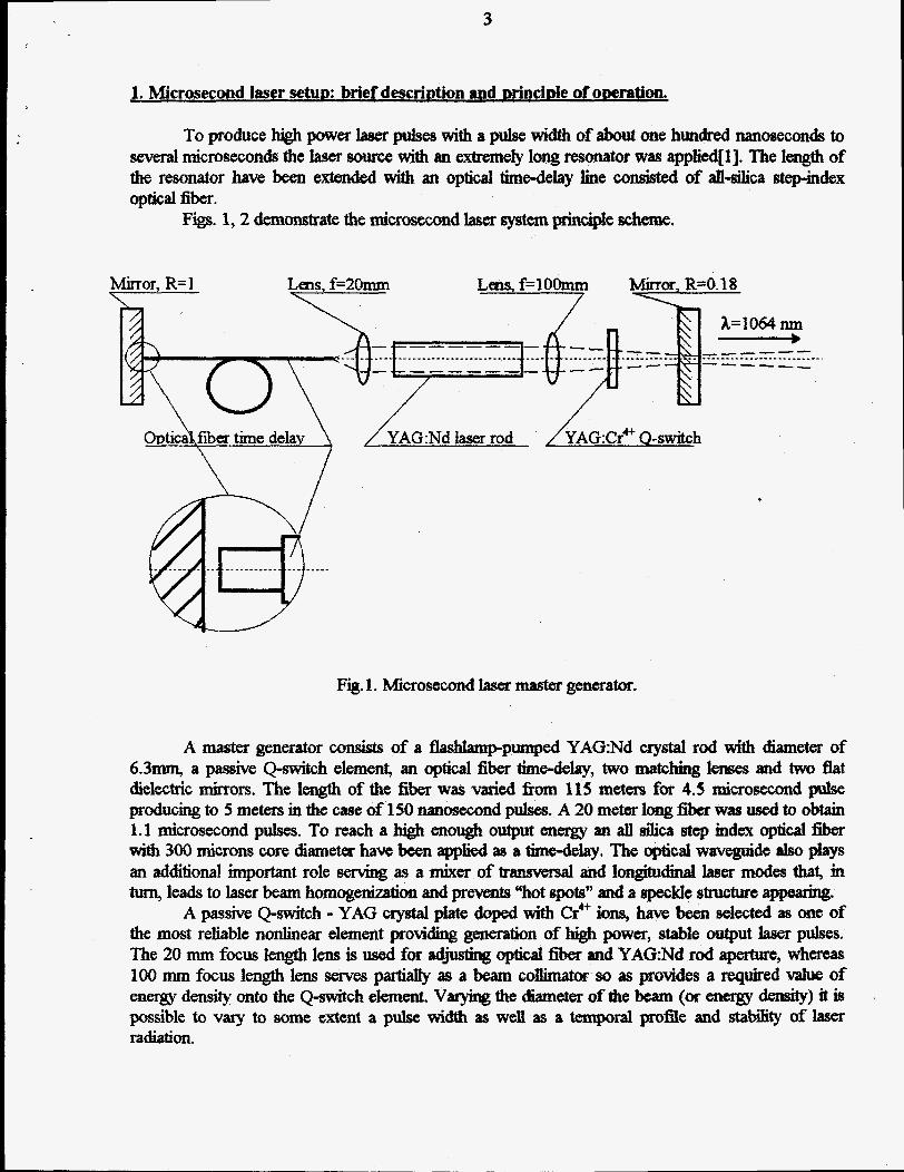
To produce high power laser pulses with a pulse width of about one hundred nanoseconds to several microseconds the laser source with an extremely long resonator was applied[l]. The length of the resonator have been extended with an optical time-defay line wnshted of atl4Iica step-index optical fiber.
Figs. 1,2 demonstrate the microsecond laser system principle scheme.
Mirror R=l .i--?--
Lens. f=Zfhnm 7
Lens, f=lOOmm ;
Mirror, R=O.18
c- m------
Opticakfiba time delay \ \ /
/ YAG:Nd laser I
Fig. 1. Microsecond laser master generator.
A master generator ConSisI of a aashtamp-pumped YAc3:Nd crystal rod with diameter of 6.3- a passive Q-switcb element, an optical fiber timedelay, two matching h s e s and two flat dielectric mirrorS. The length of the fiber was varied from 115 meters for 4.5 rrdcrosecond pulse producing to 5 metem in the case of 150 Nmosecond pulses. A 20 meter long fiber was used to obtain 1.1 microsecond pulses. To reach a high enough output energy iin all silica step index optic& fiber with 300 microns core &metes have been applied as a timedelay. The Meal waveguide also plays an additional important role serving as a mixer of t r b and longitudinal laser modes that, m turn, leads to laser beam homogenization and prevents “hot ,pots” and a speckle structure appearin@;.
A passive Q-switch - YAG crystal plate doped with Cr4’ ions, have been selected as one of the most reIiable nonlinear dement providing generation of high power, stable output laser putseS. The 20 mm focus length lens is used for &&sting optieal fiber and YAG:Nd rod aperhae, whereas 100 mm focus length lens saves parhlly as a beam collimator so as provides a required value of energy density onto the Q-switch element. Varying the diameter of the beam (or eneqy derrsity) it is possible to vary to some extent a pulse width as well as a temporal profile and stabsty of laser radiation.
4
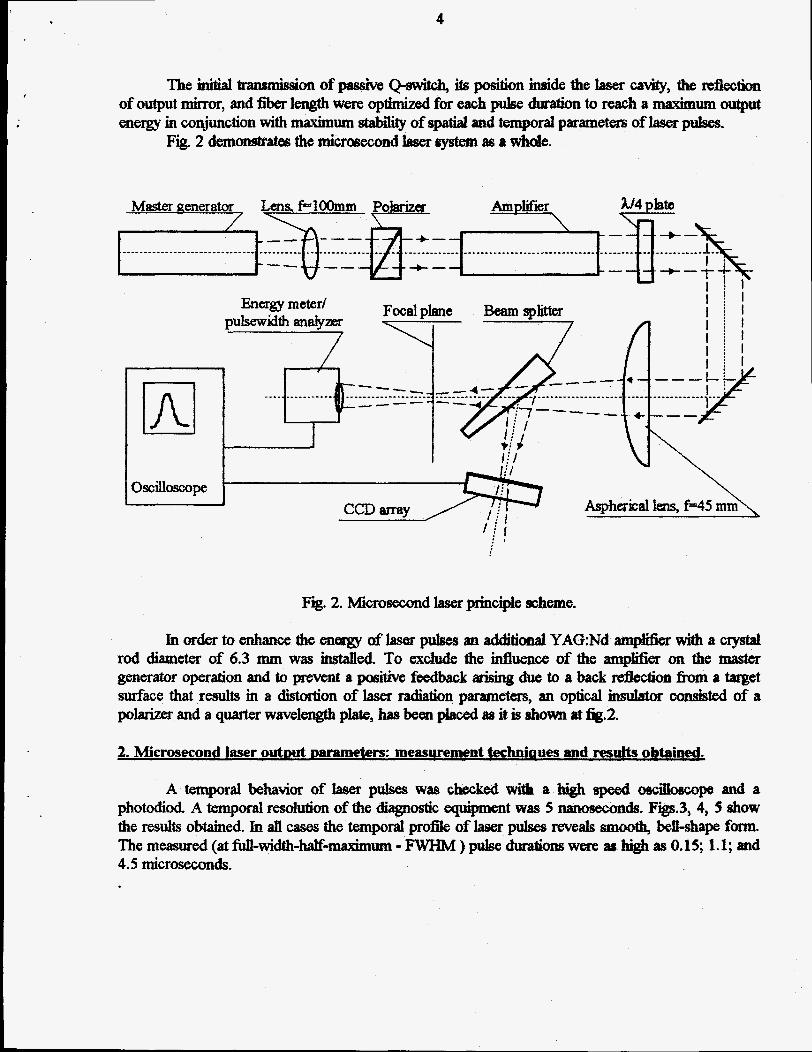
The initial transmhsion of pasaivs Q-swhh, its position h i d e the laser cavity, the reflection of output mirror, and fiber length were optimized for each pulse dwration to reach a maximum output energy in conjunction with maximum &ab%ty of spatial and temporal parametem of laser pulses.
Fig. 2 demonstrates the ndcrasecond laser system as a W e .
+--- -----_
oscill-pe
Fig. 2. Microsecond laser pzhciple scheme.
Inordertoenhancetheenerrgyof~pulsesanadditionatYAG:Ndanzpfi6ier~acrystrtl rod diameter of 6.3 mm was hstaIled. To exclude the influence of the amplifier on the master generator ojxxation and to prevent a positive feedback arising due to a back reflection h m a met sdace that r d t s m a distortion of laset. radhtkm parameters, an optical insutator m i s t e d of a polarizer and a quarter wavelength plate, has been placed as it is shorn at fig.2.
2. Microsecond laser outmt Daramefe rs: maswement techniaues and resub obtained.
A temporal behavior of I;tser pulses was checked with a high speed osdbscope and a photodid. A temporal resolution of the diagnostic equipment was 5 nanoseconds. Figs.3,4,9 show the results obtained. In all cases the temporal pro% of h e r pulses reveats smooth, beil-shape fonn. The measured (at fidl-width-M-&uin - FWHM ) p u b durations were as high as 0.15; 1.1; and 4.5 microseconds.

5
Fi3. Tempml dkMmlkm of 150 nanosecond laser pulses. Scale - 100 xu/&.
Fig. 4. Tempotal distribution of 1.1 microseoond farrer pulses. Scale - 500 nddiv
6
!
I I
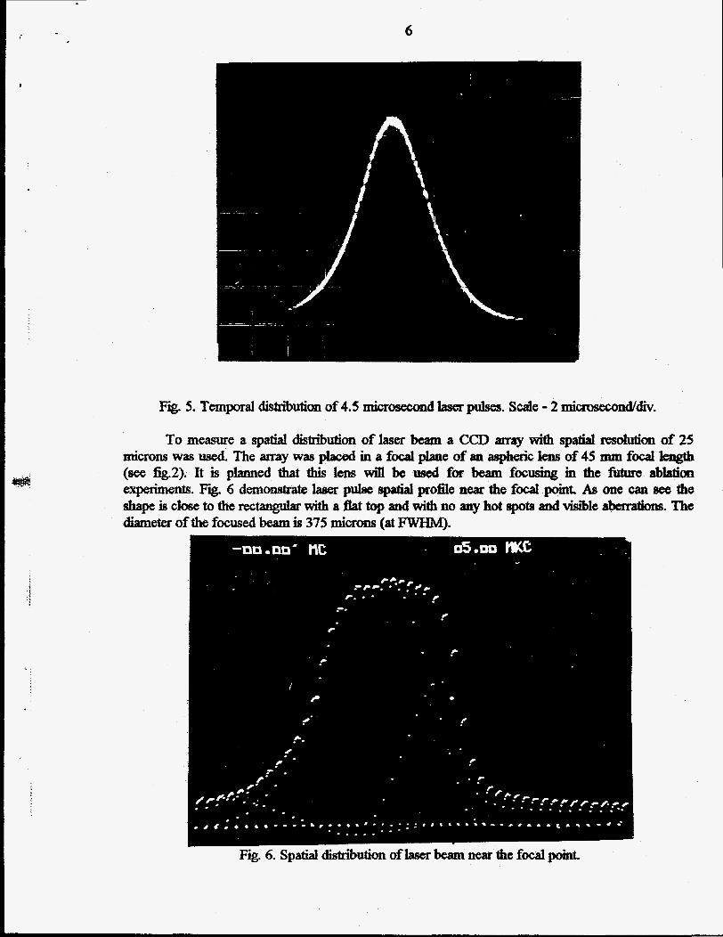
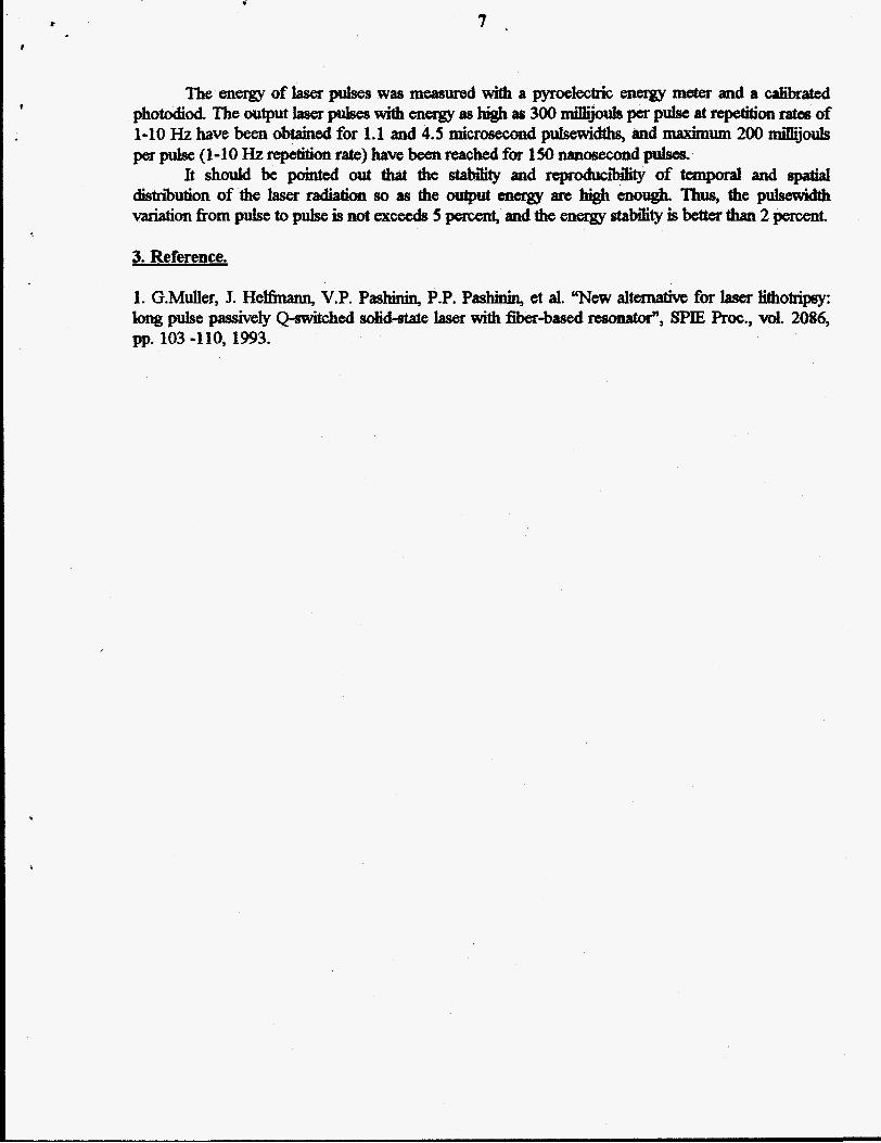
Fig. 5. Temporal dktriiution of 4.5 I I . l i c r o s e c o n d laser pulses. Scale - 2 mi-&&.
To measure a spatial dist&ution of laser beam a CCD amy with Spatiat Tesohlfion of 25 microns was used The array was placed in a focal w e of an aspheric €ens of 45 mm focaI length (see fig.2). It is planned that this lens win be used fm beam focusiag in the firture ablation experiments. Fig. 6 demonstrate laser pulse spatial p o s e near the f d pomt. As one can see the ahape is croSe to the rectangular with a flat top and with no any hot spots andvisr'be aberrations. The diameter of the focused beam is 375 microns (at FWHM).
.- .
..
r
?
The energy oflaser pulses was measured with a pyroelectric energy lELefef and a cplibtated photodioa The output laser pukes with enwas highas 300 &.&per pulse at repetition rata of 1-10 Hz have been obtained for 1.1 and 4.5 microsecond pulsewicttha and maximum 200 di jouls ~ p u l s e ( 1 - 1 O H z ~ ~ ~ ~ ) ~ e b e e n ~ h ~ f o r 1 5 0 n a n d p u l s e s .
It should be pointed out that the stability and reproctucr'bility of temporal and spatia distriion of the laser radiation so as the output cttergy are high enough. Thus, the pulsewidth d m f i o m pulse topulse is not excetds 5 percent, and the energy stabilityis better durn 2 percent.
?
3. Reference.
1. G.Muller, J. HeEinann, V.P. Pasbinin, P.P. Pashinin, et al. "New dternathe for laser fithotripsy: pulse passively Q+mit&ed diddate laser with fiber-bd re-, SPJE Proc., vol. 2086,
p ~ . 103 -110,1993.
c