laser doppler flowmetry - biopac · laser doppler flowmetry (or simply “ldf”) is an established...
TRANSCRIPT

PRODUCT SHEET
[email protected] [email protected] www.biopac.com
BIOPAC Hardware | Laser Doppler Flowmetry | Page 1 - 19 Updated: 12.1.2018
LASER DOPPLER FLOWMETRY (LDF) - click page number to jump to section LDF100C Laser Doppler Flowmetry Module: Controls & Specifications - page 2 TSD140 Series Laser Doppler Probes, Options, Handling, Applying, Quick Setup, Intro - page 4 LDFCAL Calibration Kit - page 6 LDF Calibration Procedure - page 7 Software Setup - page 8 Connecting Probes – page 9 LDF Safety & Warnings, Storage, Maintenance & Cleaning - page 12 Troubleshooting - page 14 LDF – Basic Principles - page 17
Sample blood perfusion data acquired with the LDF100C
Laser Doppler Flowmetry (or simply “LDF”) is an established and reliable method for the measurement of blood perfusion in microvascular research. Most LDF applications are concerned with monitoring the competence of regional (microvascular) blood supply following trauma, degenerative and pathological disease, surgical intervention and drug therapy.
LDF measurements are performed with the Laser Doppler Flowmetry module (LDF100C) and a wide range of fiber-optic based probes (TSD140 series) in order to access the tissue. Probes include small and lightweight probes for (non-invasive) skin and tissue surface measurements and needle type probes for direct (invasive) measurements within tissue, such as muscle and organ. Double-sided adhesive rings (ADD200 series) can be used to attach surface type probes to tissue; one size of ring fits both standard and miniature surface probes
LDF Calibration requires a calibration kit (LDFCAL), which includes a motility standard and positioning device to hold a probe in the solution during calibration. The motility standard comprises a carefully controlled solution of microspheres undergoing Brownian motion, which provides a standard calibration value of 1000 BPU ±5% at 21° C.
Unpacking LDF Components
IMPORTANT: It is essential that the Warnings and Cautions are fully understood before the LDF100C is used.
1. Inspect the packaging for damage before unpacking the component(s). • If the outer packaging or carton is wet or damaged in any way, immediately notify the shipping agent and
file a claim. It is the receiver’s duty to notify the specific carrier’s local office. In the event of any damage, please save the shipping carton as evidence.
2. Unpack the component(s) and check the part(s) against the enclosed packing slip. 3. Remove the packaging and check for signs of obvious damage or defect either to the main body of the
LDF100C module or the TSD140 series laser Doppler probes. • Contact BIOPAC Systems, Inc. for replacement of any damaged component.
PRODUCT SHEET
[email protected] [email protected] www.biopac.com
BIOPAC Hardware | Laser Doppler Flowmetry | Page 2 - 19 Updated: 12.1.2018
LDF100C Laser Doppler Flowmetry Module The LDF100C is a laser Doppler microvascular perfusion module that is capable of monitoring red blood cell (erythrocyte) perfusion in the microcirculation of a tissue. This module uses a Laser Doppler Flowmetry technique.
• Microvascular blood perfusion is indicated on the AcqKnowledge software display in relative units called Blood Perfusion Units (BPU).
• In common with all LDF devices, quantitative measurements of tissue blood perfusion in absolute units (e.g. ml/min/g of tissue) are not possible with the LDF100C.
The LDF100C laser Doppler microvascular perfusion module works by illuminating tissue with low power laser light using a probe (TSD140 series) containing optical fiber light guides. Laser light from one fiber is scattered within the tissue and some is scattered back to the probe. Another optical fiber collects the backscattered light from the tissue and returns it to the module. Most of the light is scattered by tissue that is not moving but a small percentage of the returned light is scattered by moving red blood cells. The light returned to the module undergoes signal processing to extract the signal related to the moving red blood cells.
The LDF100C is not a medical device. It is not designed for the diagnosis, mitigation or treatment of disease in humans. Flow/flux/perfusion has the SAME meaning—this manual and the module uses the term “flow.”
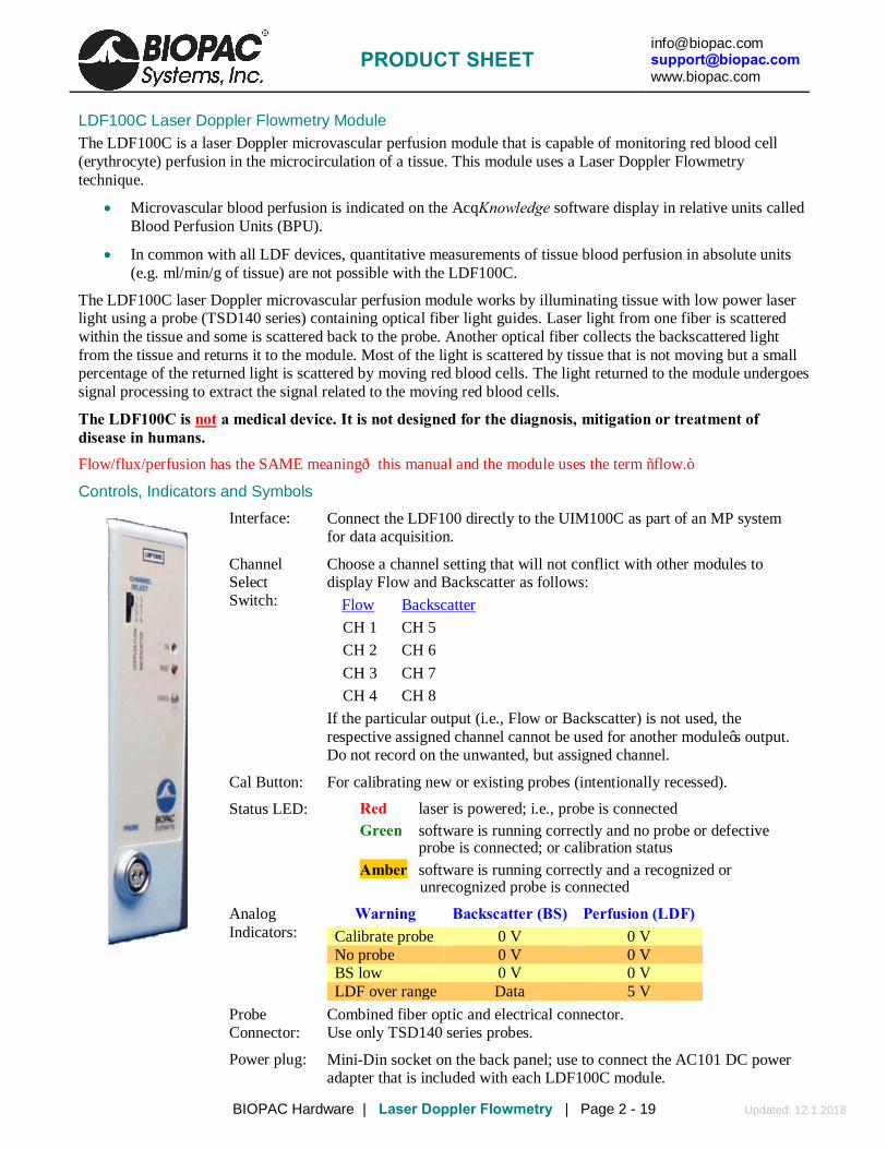
Controls, Indicators and Symbols
Interface: Connect the LDF100 directly to the UIM100C as part of an MP system for data acquisition.
Channel Select Switch:
Choose a channel setting that will not conflict with other modules to display Flow and Backscatter as follows:
Flow Backscatter CH 1 CH 5 CH 2 CH 6 CH 3 CH 7 CH 4 CH 8
If the particular output (i.e., Flow or Backscatter) is not used, the respective assigned channel cannot be used for another module’s output. Do not record on the unwanted, but assigned channel.
Cal Button: For calibrating new or existing probes (intentionally recessed).
Status LED: Red laser is powered; i.e., probe is connected Green software is running correctly and no probe or defective
probe is connected; or calibration status Amber software is running correctly and a recognized or
unrecognized probe is connected
Analog Indicators:
Warning Backscatter (BS) Perfusion (LDF) Calibrate probe 0 V 0 V No probe 0 V 0 V BS low 0 V 0 V LDF over range Data 5 V
Probe Connector:
Combined fiber optic and electrical connector. Use only TSD140 series probes.
Power plug: Mini-Din socket on the back panel; use to connect the AC101 DC power adapter that is included with each LDF100C module.
PRODUCT SHEET
[email protected] [email protected] www.biopac.com
BIOPAC Hardware | Laser Doppler Flowmetry | Page 3 - 19 Updated: 12.1.2018
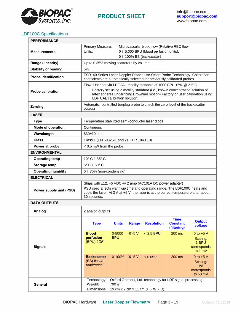
LDF100C Specifications PERFORMANCE
Measurements Primary Measure: Microvascular blood flow (Relative RBC flow Units: 0 – 5,000 BPU (blood perfusion units); 0 – 100% BS (backscatter)
Range (linearity) Up to 0.35% moving scatterers by volume
Stability of reading 5%
Probe identification TSD140 Series Laser Doppler Probes use Smart Probe Technology. Calibration coefficients are automatically selected for previously calibrated probes
Probe calibration
Flow: User set via LDFCAL motility standard of 1000 BPU ±5% @ 21° C Factory set using a motility standard (i.e., known concentration solution of
latex spheres undergoing Brownian motion) Factory or user calibration using LDF CAL calibration solution.
Zeroing Automatic, controlled (unplug probe to check the zero level of the backscatter output)
LASER Type Temperature stabilized semi-conductor laser diode
Mode of operation Continuous
Wavelength 830±10 nm
Class Class 1 (EN 60825-1 and 21 CFR 1040.10)
Power at probe < 0.5 mW from the probe
ENVIRONMENTAL
Operating temp 10° C – 35° C
Storage temp 5° C – 50° C
Operating humidity 0 – 70% (non-condensing)
ELECTRICAL
Power supply unit (PSU)
Ships with ±12, +5 VDC @ 2 amp (AC101A DC power adapter) PSU spec affects warm-up time and operating range. The LDF100C heats and cools the laser. At 3 A at +5 V, the laser is at the correct temperature after about 30 seconds.
DATA OUTPUTS
Analog 2 analog outputs
Signals
Type Units Range Resolution Time
Constant (filtering)
Output voltage
Blood perfusion (BPU) LDF
0-5000 BPU
0 -5 V < 2.5 BPU 200 ms
0 to +5 V Scaling: 1 BPU
corresponds to 1 mV
Backscatter (BS) tissue remittance
0-100% 0 -5 V ≤ 0.05% 200 ms 0 to +5 V Scaling:
1% corresponds
to 50 mV
General Technology: Oxford Optronix, Ltd. technology for LDF signal processing Weight: 790 g Dimensions: 19 cm x 7 cm x 11 cm (H × W × D)

PRODUCT SHEET
[email protected] [email protected] www.biopac.com
BIOPAC Hardware | Laser Doppler Flowmetry | Page 4 - 19 Updated: 12.1.2018
TSD140 Series Probes
The TSD140 series offers a wide range of laser Doppler probes that interface with the LDF100C module. Probes are designed to allow the local monitoring of blood perfusion from almost any tissue type. All probes contain optical fibers, which are used to direct low power laser light to and from the tissue. Three types of probes (surface, needle, and disposable) and a driver are stocked for the LDF100C; other probes styles are available. Standard cable length for all probes is 3 m. Single fiber probes have an overall length of 30-100 cm and require the use of TSD148; they can be cut to any length with a sharp scalpel.
Probe cable lengths between 1 m and 8 m and needle and needle probes with shaft lengths of between 10 mm to 70 mm may be custom ordered. Contact BIOPAC Systems, Inc. for more information.
Probe Options SURFACE Designed for skin and exposed tissue blood flow monitoring. Ideal for noninvasive measurements
from skin or organ surfaces. The signal delivery fiber intersects the probe body at a right angle, making the probes easy to secure to the skin or tissue surface. Made from Tempalux.
TSD140 Cutaneous blood flow anywhere on the skin surface.
TSD142 Micro-vascular skin blood flow in the digits.
TSD143 Small animal work, including post-operative monitoring, i.e., reconstructive surgery (suturable).
TSD146 Small animal work and general tissue surface monitoring (this is a non-suturable version of the TSD143).
NEEDLE Designed for invasive and endoscopic blood flow monitoring of tissue. Needle probes can be used both for noninvasive monitoring from the surface of tissues (by positioning the tip in contact/close proximity to the tissue) or for invasive placement and monitoring from regions within tissues. The signal delivery fiber terminates flush with the top of the needle, making the probes easy to insert into tissue. Made from medical grade stainless steel.
TSD144 Microvascular blood flow measurements. Typically positioned using a micromanipulator clamp over soft tissues such as brain and muscle.
TSD145 Micro-vessel or micro-vascular blood flow within skin, muscle, tumor and organ tissues. Fine probe diameters facilitate blood flow measurements from only a small number of capillaries.
DISPOSABLE Designed for safe, continuous, invasive microvascular blood flow monitoring. Composed of a polymethyl methacrylate core and a tough fluorinated polymer cladding. Incorporate a coupling bead to interface with the TSD148 single fiber driver for connection to the LDF100C module.
TSD147A/AL Blood flow measurements under the skin (use a standard 22G ID cannula to insert directly into tissue). TSD147A is 30 cm long, TSD147AL is 100 cm long.
MRI Use: MR Safe TSD147A/AL Components – MRI chamber room; cable only: Fiber Optic Cable: Polymethyl methacrylate core & tough fluorinated polymer cladding
PRODUCT SHEET
[email protected] [email protected] www.biopac.com
BIOPAC Hardware | Laser Doppler Flowmetry | Page 5 - 19 Updated: 12.1.2018
DRIVER
TSD148 This is a precision-machined coupling system for interfacing the TSD147 series single fiber probes to the LDF100C. The TSD148 consists of a compact laser driver housed in a non-metallic Tempalux housing, terminated with a 2-meter cable for connection to the LDF100C module.
Handling TSD140 Series Probes
TSD140 series probes must be handled with care. Failure to do this may result in breakage of the internal optical fibers, scratching the polished probe ends or separation of the cable from the probe ends or connectors.
Do not use a worn or damaged probe. The optical fibers used in the TSD140 series probes are glass and have a diameter of 125 μm. The fibers are flexible and can be bent; however, it is recommended that they are not subjected to bends with a radius less than 30 mm.
The connectors on TSD140 series probes must be kept clean and free from dust. Connectors should be inspected before each use. Dust can be removed from the connectors using a good quality ‘air-duster.’
Check the integrity of TSD140 series probes by holding the probe end to a source of bright diffuse light (e.g. a lamp) and inspecting the connector end. Two bright spots of light of equal intensity should be visible from the pins within the connector.
Applying Probes to Tissue Surface Surface probes may be attached to tissue using double-sided adhesive rings (such as ADD204 or
ADD208). Alternatively, the miniature suturable probe can be sutured directly into position.
Needle Needle probes can be secured in a micromanipulator assembly or stand and placed above the tissue. Depending on the tissue, fine needle probes may be introduced directly into tissue after first ensuring an appropriate superficial incision has been made. Alternatively, a suitable introducer or catheter should be used. All needle style probes can optionally be secured in a micromanipulator assembly or stand.
• Bear in mind that all needle probes have a blunt end and may cause some degree of tissue trauma when inserted directly into tissue without using a suitable introducer.
Single fiber The insertable probe can be inserted into tissue using a standard 2G ID cannula. These probes can be cut to the desired length with a sharp scalpel. The single fiber probes require the TSD148 driver.
It is important to control the relative movements of the tissue (induced by breathing, etc.) with respect to the probe to reduce artifact in the perfusion signal. Allowing the supported probe to lightly come into contact with the surface of the tissue can reduce these artifacts. Under some conditions it may be best to hold the probe in position by hand.
It is essential to ensure that the pressure on the tissue is minimal, otherwise local occlusion of the microvasculature may result.
Avoid direct illumination of the measurement site from external lighting sources and direct sunlight. Excessive ambient lighting at the probe site can disturb the blood perfusion reading. If erroneous readings due to excessive ambient lighting levels are suspected, cover the attached probe and measurement area with a light piece of opaque material.
● Place the LDF100C module on a flat surface close to the point of measurement; note that the standard probe cable length is 3 m.
● The probe can be placed in or on tissue at any stage, either prior to or following connection to the LDF100C. Allow the module to warm up with a probe attached before taking any measurements.
● The probe can be exchanged for another at any stage without the need to first switch off the LDF100C.
PRODUCT SHEET
[email protected] [email protected] www.biopac.com
BIOPAC Hardware | Laser Doppler Flowmetry | Page 6 - 19 Updated: 12.1.2018
● The probe does not need to be disconnected from the LDF100C prior to turning off the LDF100C.
Quick Set up and Use Guide Place the LDF100C module on a flat surface close to the point of measurement. Connect the AC101 to the LDF100C and plug the AC101 into a properly grounded AC Mains socket.
● When the module is powered (immediately after the double beep) the analog outputs both go to 0 V (half scale) for 3 sec and then to 0 V for a further 3 sec before outputting data.
Allow the instrument to warm up for 5 minutes before making any measurements. Select a probe to make measurements with and connect it respecting the correct orientation. If no probe is
connected to the LDF100C module, the Flow analog output will be held at 0 V and the Backscatter output at 0 volts. The status LED will be green when no probe is connected.
Introduction to Probe Calibration The LDF100C system incorporates proprietary Smart Sensor technology that enables the module to recognize a previously calibrated probe and to automatically apply the necessary probe calibration coefficients. This alleviates the need to re-calibrate a probe every time a different probe is plugged in to the module. The module ‘recognizes’ a specific probe every time the probe is plugged in. When probes are ordered at the same time as the LDF100C, BIOPAC will calibrate the LDF100C to the ordered probes with a “motility standard” before shipping the items. If a probe has previously been calibrated then there is generally no need to re-calibrate that probe. However, when probes are purchased separately they will require calibrating before use using an LDF CAL calibration kit. When the calibration procedure ends, the calibration data is automatically stored in the module. The calibration data is automatically retrieved every time that particular probe is connected to the module. LDFCAL Calibration Kit
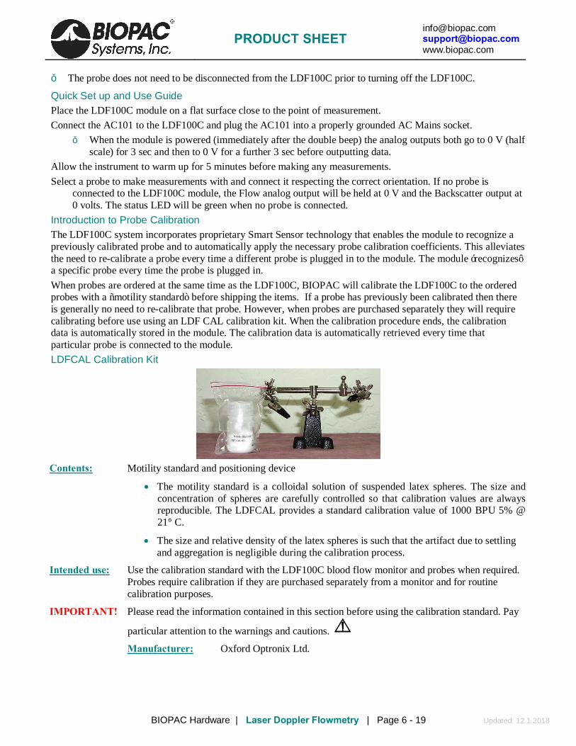
Contents: Motility standard and positioning device
• The motility standard is a colloidal solution of suspended latex spheres. The size and concentration of spheres are carefully controlled so that calibration values are always reproducible. The LDFCAL provides a standard calibration value of 1000 BPU 5% @ 21° C.
• The size and relative density of the latex spheres is such that the artifact due to settling and aggregation is negligible during the calibration process.
Intended use: Use the calibration standard with the LDF100C blood flow monitor and probes when required. Probes require calibration if they are purchased separately from a monitor and for routine calibration purposes.
IMPORTANT! Please read the information contained in this section before using the calibration standard. Pay
particular attention to the warnings and cautions.
Manufacturer: Oxford Optronix Ltd.

PRODUCT SHEET
[email protected] [email protected] www.biopac.com
BIOPAC Hardware | Laser Doppler Flowmetry | Page 7 - 19 Updated: 12.1.2018
Probe Calibration Procedure—TSD140-TSD147 ● To calibrate the single fiber driver adapter (TSD148), refer to the next section.
To perform a new probe calibration, a Calibration Kit (LDFCAL) is required, which contains a motility standard and a positioning device. The parameters are automatically stored and recalled when that particular probe is subsequently connected.
Every probe is supplied with a probe identification number (Probe ID) on the probe box label. The number is between 5 and 36 and must be unique for the probes used; using two probes with the same ID will result in invalid calibration data being used.
Calibration errors may occur if probes with the same probe identification number are used. Contact BIOPAC for advice if multiple probes have the same ID number.
The motility standard has a 3-month shelf life, so it’s best to order only when required. The expiration date is indicated on the label. The solution must not be used beyond this date, as it will produce misleading values due to the aggregation of the latex spheres.
Do not use the motility standard in ambient temperatures below 15° C or above 25° C.
Store the motility standard within the temperature range 3 – 25° C. Do not freeze the solution.
Never attempt to re-fill the bottle with spilt solution. Errors may arise as a result of contamination.
Do not dilute the motility standard.
It is essential that the calibration procedure be performed on a stable and vibration-free surface. This is very important, any movement or vibration during the calibration procedure, however slight, is likely to result in erroneous calibration data.
1. Connect the probe to the front panel of the blood flow monitor.
2. Gently swirl the bottle to disperse the contents.
3. Open the bottle and allow the contents to settle for one minute before proceeding.
4. Carefully position the probe in the solution. This is best achieved by holding the probe cable within the jaws of the clamp and carefully lowering the active area of the probe into the center of the solution.
IMPORTANT! Keep the active surface of the probe as far as possible from the edge of the bottle. The probe should be supported in such a way that it does not swing or move while it is in the solution.
Read through all the instructions first before proceeding.
5. Press the CAL button on the front panel of the LDF100C once and then press the CAL button again within 10 seconds to confirm calibration. To end calibration at this point, wait 10 seconds and the calibration process will time out and stop. If proceeding, there will be one long beep.
IMPORTANT! Any vibration or movement during this period will invalidate the calibration procedure.
6. An audible double beep indicates a successful calibration.

PRODUCT SHEET
[email protected] [email protected] www.biopac.com
BIOPAC Hardware | Laser Doppler Flowmetry | Page 8 - 19 Updated: 12.1.2018
• A series of audible beeps (long beep followed by a pause and then a number of rapid beeps) indicates a failed calibration. The number of rapid beeps equates to the error code—refer to Troubleshooting for more information on the error codes.
Driver Calibration Procedure— TSD148 ● To calibrate a probe (TSD140-TSD147), refer to the preceding section.
1. IMPORTANT! Read the following information before attempting to calibrate the single fiber probe
connecting adapter. Refer to calibration standard instructions for precautions to be taken.
2. Unscrew Part A.
3. Pull off Part B. (Note: This is a tight fit and may need to be twisted while it is pulled.)
4. Connect the single fiber adapter into the front panel of the blood flow monitor.
5. Gently swirl the bottle to disperse the contents before use. Open the bottle and allow the contents to settle for one minute before proceeding.
6. Carefully position Part C of the adapter in the solution. This is best achieved by holding the adapter cable within the jaws of the clamp and carefully lowering Part C into the center of the solution.
IMPORTANT! Keep the active surface of the probe as far as possible from the edge of the bottle. The adapter cable should be supported in such a way that it does not swing or move while in the solution. Follow the calibration procedure detailed in the preceding section.
7. Clean Part C to remove residual calibration solution by washing and wiping using water or 70% IMS or IPA. Allow Part C to dry before reassembling the adapter by pushing Part B onto Part C and then attaching Part A.
Software Setup (AcqKnowledge 4.1 and higher) In AcqKnowledge versions 4.1 and higher, use Module Setup to select the LDF100C hardware and automatically set the scaling.
1. Launch AcqKnowledge, choose “LDF100C” from the “What type of module should be added?” dialog and click “Add.”
(If Module Setup does not appear automatically, go to the MP menu > Set Up Data Acquisition > Channels and click the “View by Modules” button. Then click “Add a New Module.”)

PRODUCT SHEET
[email protected] [email protected] www.biopac.com
BIOPAC Hardware | Laser Doppler Flowmetry | Page 9 - 19 Updated: 12.1.2018
2. Make sure the Channel Select setup dialog is set to “1-5” and click OK. (“Flow” will be assigned Channel A1 and “Backscatter” will be assigned Channel A5.)
Software Setup (AcqKnowledge 4.0 and earlier) AcqKnowledge must be set to scale the input values to the correct units for LDF measurements. Access the Scaling Parameters dialog under MP menu>Set Up Data Acquisition > Channels >Setup, and set the parameters for “Flow” (Channel A1) and “Backscatter” (Channel A5) as follows: Flow (A1)
Input Scale Units Cal1 5 5000 BPU Cal2 0 0
Backscatter (A5)
Input Scale Units Cal1 5 100 % Cal2 0 0
Connecting Probes to the LDF100C Very carefully remove the probe from its protective case and check that the Probe Connector is clean and free from dust. The TSD140 series probes plug into the front of the LDF100C module, which contains the laser source, sensitive photo-detection and signal processing circuitry. All probes are standardized using a reference motility standard (LDFCAL) consisting of latex microspheres undergoing Brownian motion. Connect the LDF100C module to a power source and then switch ON.
• The LED status indicator will be illuminated in Amber. (When the probe is not inserted, the indicator will illuminate Green only.)
• The start-up beeps are the same whether a probe is connected or not and whether a probe is calibrated.
• Analog indicators
● no probe: BS = 0 V, LDF = 0 V
● uncalibrated probe: BS = 0 V, LDF = 0 V
Select a TSD140 series probe. Plug the TSD140 probe into the “PROBE” connector located on the front panel of the LDF100C, taking care to
orient the connector plug with respect to the socket. Align the probe and push the connector firmly home into the socket until a click is heard.
4. After a short delay, the module will enter Trend Mode, and the AcqKnowledge software display should show blood perfusion values as XXXX BPU (where XXXX is a number in the range 0-5000 units) and backscatter as % (a percentage).
Since the LDF100C is a light-based measurement system, random values may appear on the software display while probes are not attached to tissue. When the probe is in the air, the module will set the analog outputs to BS = 0 V, LDF = 0 V instead of outputting random values.

PRODUCT SHEET
[email protected] [email protected] www.biopac.com
BIOPAC Hardware | Laser Doppler Flowmetry | Page 10 - 19 Updated: 12.1.2018
No warm up period is required after connecting a probe if the module was already ON. If the module was not ON, allow 30 seconds minimum for warm up.
Disconnect To disconnect the probe plug from the front panel socket, gently pull the connector by the ribbed part of the connector.
Attempting to remove the connector by any other part of the probe (for example, by pulling the cable sleeving) will cause irreparable damage to the probe.
TSD140 Series Probes Storage & Cleaning When not in use, TSD140 series probes for the LDF100C should be stored in the probe box with the optical fiber coiled neatly. Following sterilization, probes should be stored unopened in the packaging in which they were sterilized. Cleaning Probes are cleaned prior to packing and shipment. It is recommended that the probe end on all new probes be wiped with a soft cloth, preferably one that does not shed fibers, dampened with a solution of 70% alcohol in water. Probes should be cleaned immediately after use as it is easier to remove soiling and particulate matter before it dries onto surfaces. Visually inspect the probe end, cable and connector.
• If there is no visible soiling, wipe the probe end and cable with a soft cloth dampened with a solution of 70% alcohol in water. Allow the alcohol to dry completely before using the probe.
• If there is visible soiling, clean the probe with warm water containing a mild detergent. To ensure that all soiling and particulate matter is removed, keep the probe beneath the surface of the cleaning solution and rub it carefully with a soft cloth or brush. Avoid immersing the probe connector in the cleaning solution. Rinse the probe end and cable in clean water. Wipe the probe end and cable with an absorbent cloth and leave the probe to dry completely.
Disinfection To disinfect TSD140 series probes, immerse the probe end and cable (for the disinfectant manufacturer’s recommended immersion times) in:
• 2% glutaraldehyde (Cidex® OPA) • 70% alcohol in water
Sterilization Some of the TSD140 series dedicated perfusion probes may be sterilized by moist heat (steam). They are capable of withstanding an autoclave cycle of 134° C for 3 minutes. With care a TSD140 series probe can be expected to survive between 10 – 20 sterilization cycles.
TSD140 series probes must be cleaned prior to sterilization.
It is the responsibility of the user to validate the sterility of TSD140 series probes after sterilization.
The TSD140 series probe should be packaged to maintain sterility after processing. The packaging material used should be appropriate for sterilization by steam, e.g. a tray within a pouch. The dimensions of the base of the tray should not be smaller than 15 cm x10 cm for a standard length probe.
1. Place the probe in the tray in a neat coil. • Starting at the connector end, tape the connector to the base of the tray using autoclave tape. Coil
the probe onto the tray and lay the probe end in the center of the coil. Autoclave tape may be used to secure the cable to the tray. Do not use tape on the probe end. Do not rest the connector on the cable as it is heavy and may distort the cable.

PRODUCT SHEET
[email protected] [email protected] www.biopac.com
BIOPAC Hardware | Laser Doppler Flowmetry | Page 11 - 19 Updated: 12.1.2018
2. Seal the tray into a pouch designed to withstand sterilization by steam. 3. Use only a validated autoclave to sterilize the TSD140
series probes. • Probes can be immersed in a non-corrosive sterilizing
solution, such as 2% Glutaraldehyde (Cidex® OPA) or in a low-temperature, ethylene-oxide gas sterilization chamber. The maximum temperature to which older style probes can be exposed is 60° C.
Probe Identification The LDF100C system incorporates proprietary Smart Sensor technology that enables the module to recognize a previously calibrated probe and to automatically apply the necessary probe calibration coefficients. This alleviates the need to re-calibrate a probe every time a different probe is plugged in to the module. The module ‘recognizes’ a specific probe every time the probe is plugged in.
New Probe If a new (previously uncalibrated) probe is connected to the LDF100C module, then the module’s Flow and Backscatter outputs will be at 0 V. To take measurements, the probe must be calibrated (see following section on calibrating probes) or removed and replaced by a recognized probe. The status LED will be amber when a probe, recognized or unrecognized, is connected to the LDF100C.
Temperature Out of Range (Single beep every 16 seconds) This warning will sound if the laser temperature is below the minimum or above the maximum for stable operation. It may occur during the warm-up period if the ambient temperature is low—this is normal and not a cause for concern. If this occurs during operation, the instrument should be moved to a cooler or warmer environment depending on the ambient temperature. With the temperature out of range, output signals will continue to be generated but may no longer be within the calibrated tolerance of the system and should be interpreted with caution. If the environmental temperature is below 25° C and this message occurs repeatedly soon after power-on, then a fault may have occurred; please contact BIOPAC Systems, Inc. for further advice.

PRODUCT SHEET
[email protected] [email protected] www.biopac.com
BIOPAC Hardware | Laser Doppler Flowmetry | Page 12 - 19 Updated: 12.1.2018
TSD140 Series Probe Specifications Part # Style Suturable Body
Dimensions Angle of Laser
Delivery & Collection
Skin & Tissue Monitoring
TSD140 Standard surface. Reusable, may be
autoclaved.
no 8 mm (high) x 17 mm (dia)
Right angle to probe body
yes
TSD142 Digit surface. Reusable, may be
autoclaved.
no 10 mm (high) x 17 mm (dia)
Right angle to probe body
yes
TSD143 Suturable Miniature surface. Reusable, may be autoclaved.
yes 5 mm (high) x 12 mm (dia)
Right angle to probe body
yes
TSD144 Needle. Reusable, may be autoclaved.
no 25 mm (long) x 1 mm (dia)
Straight Invasive and endoscopic
TSD145 Fine needle. Reusable, may be autoclaved.
no 25 mm (long) x 0.5 mm (dia)
Straight Invasive and endoscopic
TSD146 Miniature surface. Reusable, may be
autoclaved.
no 5 mm (high) x 12 mm (dia)
Right angle to probe body
yes
TSD147A* Disposable, insertable single fiber. Single-use
recommended.
no 30 cm (long) x 0.5 mm (dia)
Straight Insert via 22G ID cannula
TSD147AL*
Disposable, insertable single fiber. Single-use
recommended.
no 100 cm (long) x 0.5 mm (dia)
Straight Insert via 22G ID cannula
Part # Style Used with Body
Dimensions Connection Type Cable Length
TSD148 Single fiber Driver TSD147A TSD147AL
28 mm (long) x 8 mm (dia)
In-line single fiber connector
3 meters
*Requires the TSD148 Single Fiber Driver for operation with the LDF100C. LDF Safety This section contains important safety information related to the general use of the LDF100C laser Doppler perfusion module. Important safety information also appears throughout the LDF100C and TSD140 series sections as Warnings and Cautions.
! Warning A warning indicates the possibility of injury to the operator.
A caution indicates a condition that may lead to equipment damage and/or malfunction.
LDF100C incorporates semiconductor laser diode devices operating in continuous mode and emitting invisible laser radiation at a nominal operating wavelength of 830 nm. The maximum output power at the probe tip is less than 0.5 mW. Laser light emitted from the optical fiber is highly divergent. Although the characteristics of the laser radiation place the LDF100C device within the “Class 1” classification users should avoid directing the laser radiation onto the eye. Applying the probe to any tissue OTHER THAN THE EYE is harmless, even over prolonged time periods.
Warnings ! Warning Never apply an LDF100C probe directly to the eye. The laser beam may cause permanent
damage to the retina.
! Warning Do not attempt to use the LDF100C if it is damaged or does not operate as described in this manual. There is a risk of electrical shock or other injury. The module must be returned to BIOPAC for repair.
PRODUCT SHEET
[email protected] [email protected] www.biopac.com
BIOPAC Hardware | Laser Doppler Flowmetry | Page 13 - 19 Updated: 12.1.2018
Cautions for the Module
Do not attempt to operate the LDF100C in the vicinity of imaging or therapeutic equipment that emits ionizing radiation or produces a strong magnetic field as the performance of the module may be affected. Extra long probes are available that allow the LDF100C module to be operated at a safe distance from such equipment.
Do not attempt to autoclave, pressure sterilize, or expose to radiation, any part of the module.
Do not attempt repairs to the LDF100C module or TSD140 series probes. Only BIOPAC trained personnel should undertake repairs.
Do not use the LDF100C in the presence of strong or changing ambient lighting levels as this may result in erroneous measurements and artifacts.
Do not use probes, cables and other accessories unless supplied by BIOPAC, otherwise serious damage may result.
Do not mishandle the module; use extreme care at all times.
Do not use the module in the presence of flammable anesthetics, which represent an explosive hazard.
Cautions for the Probes
Do not drop, pull, stretch or apply mechanical shock to a TSD140 series probe. Permanent damage to the probe may result.
Do not apply tension to the probe cable. Permanent damage to the probe may result.
Do not soak or immerse the probe in any corrosive liquid solution. Permanent damage to the probe may result.
Do not mishandle. Handle the probes with great care to avoid breaking the optical fibers, scratching the polished ends or separating the probe ends or connectors from the fibers.
Maintenance User Responsibility
Never use a defective product. Replace parts that are missing, broken, worn or damaged in any way immediately. This product (or its components) should be repaired only by BIOPAC Systems, Inc. trained engineers. Any exceptions to this recommendation must be made using written instructions supplied by BIOPAC Systems, Inc. If service is not provided by BIOPAC Systems, Inc. (or its appointed agents) then the user of this product will have the sole responsibility for any losses incurred as a result of unauthorized maintenance, improper repair, alterations or damage.
LDF100C ! Warning Only BIOPAC technical staff should remove the cover of the LDF100C module. There are no
user-serviceable parts inside. Inspect the module regularly for signs of wear and tear.

PRODUCT SHEET
[email protected] [email protected] www.biopac.com
BIOPAC Hardware | Laser Doppler Flowmetry | Page 14 - 19 Updated: 12.1.2018
Checking TSD140 Series Probes Inspect TSD140 series probes regularly to check the integrity of the internal optical fibers.
• A simple check is to hold the probe end to a source of bright diffuse light (e.g. a lamp) while visually inspecting the connector end. Two bright spots of light of equal intensity should be visible from the two large pins within the connector.
LDF100C Storage & Cleaning When not in use, the LDF100C module should ideally be stored at room temperature, although it may be stored between 5° C to 50° C. When returning from extremes of temperature, it is important to allow the module to stabilize at room temperature before use.
To clean the surface of the module: wipe lightly with a dry, lint-free cloth. Or wipe lightly with a soft cloth dampened with a commercial, nonabrasive cleaner, or use a low-pressure air line to blow dust free, or carefully clean with a suitable vacuum cleaner.
To disinfect the module, wipe the surface with a soft cloth dampened with a solution of 70% alcohol in water.
! Warning Do not spray, pour or spill any liquid on the LDF100C module, its accessories, connectors, switches or openings.
Troubleshooting ! Warning Only BIOPAC technical staff should remove the cover of the LDF100C module. There are no
user-serviceable parts inside.
Use of controls or adjustments or performance of procedures other than those specified herein may result in hazardous radiation exposure.
Contact [email protected] for problems using the LDF100C.
Beep & Led Guide Beep LED Indication Two beeps Off Initializing with no probe. Two beeps Red Initializing with a probe connected. — Green Instrument ready for use; no probe connected. — Amber Instrument operating correctly with probe connected. Single beep every 16 seconds
Amber or green Laser temperature out of range (too hot or too cold).
Double beeps
Alternating amber/red, synchronized with beeps
Calibration button was pressed, awaiting confirmation. Note If the calibration button was pressed in error, wait 10
seconds for normal operation to resume. To confirm calibration, press the calibration button again during that 10-second period.
Long beep Alternating amber/red Calibration in progress. Double beep Amber Calibration successful. Long beep followed by a number of short beeps indicating the error.
Alternating red/amber, synchronized with error code beeps
Calibration failed. Error: 1, 2, 3, 4, 7 Incorrect probe position or malfunctioning probe.
Reposition probe in motility standard and repeat calibration procedure.
Error: 5, 6 Vibration or movement of probe or cable. Ensure LDFCAL motility standard is on a vibration-free surface and eliminate probe and cable movement; repeat calibration procedure.
Single beep Amber Calibration aborted (probe removed or calibration button pressed).

PRODUCT SHEET
[email protected] [email protected] www.biopac.com
BIOPAC Hardware | Laser Doppler Flowmetry | Page 15 - 19 Updated: 12.1.2018
Reducing Signal Artifact
Certain environmental conditions and probe application and positioning errors can affect laser Doppler blood perfusion readings.
Irrespective of the probe used, it is important to reduce the possibility of signal artifact, noise and signal dropout in the blood perfusion reading. The presence of motion artifact noise in the blood perfusion signal is often due to relative movements of the tissue (e.g. induced by breathing) with respect to the probe and/or probe cable movements. To minimize artifact, allow the probe to come into contact with the tissue such that the probe and tissue ‘move together’ and ensure that the cables do not move. It may be helpful to secure the probe cable to the table with adhesive tape at intervals.
It is also essential to ensure that undue probe pressure is not applied to the tissue, otherwise local occlusion of the microvasculature may result in a corresponding reduced blood perfusion reading.
Excessive ambient lighting at the probe measurement site can also disturb the blood perfusion reading. Avoid direct illumination of the measurement site from external lighting sources and direct sunlight. If erroneous readings due to excessive ambient lighting levels are suspected, cover the attached probe and measurement area with a light piece of opaque material.
In summary, avoid the following situations:
• Probe movement relative to the tissue.
• Movement of the probe cables.
• Strong ambient lighting sources such as surgical lights, fluorescent lights and direct sunlight.
• Changing ambient lighting.
Loss of signal due to excessive tissue occlusion could occur for the following reasons:
• Excessive probe pressure on the tissue.
• The formation of a hematoma (blood clot) within the tissue.
Electro-Magnetic Interference
With the proliferation of radio-frequency transmitting equipment and other sources of electrical noise in research environments (e.g. mobile phones, electrical appliances), high levels of such interference due to close proximity or strength of a source may result in disruption of performance of this device.
Erratic readings, cessation of operation or other incorrect functioning may indicate electro-magnetic interference to the module. If this occurs, survey the location of use to determine the source of the disruption and take actions to eliminate it:
• Turn equipment off in the vicinity of the module to isolate the equipment generating the electromagnetic interference.
• Relocate the other device(s).
• Increase the separation between the interfering equipment and the LDF100C module.
For further information and assistance contact BIOPAC.

PRODUCT SHEET
[email protected] [email protected] www.biopac.com
BIOPAC Hardware | Laser Doppler Flowmetry | Page 16 - 19 Updated: 12.1.2018
Possible Errors & Suggestions A. There is no response to the Power On button and the Power On LED indicator fails to light green.
The power adapter may not be properly connected to the LDF100C or to the Mains outlet, or it may not be functioning. Check all connections. If possible, try another adapter with the same specification; the adapter must have the same specification to maintain electrical safety.
B. There is no double beep upon power on and/or the initial beep does not occur.
If the power on indicator is not lit, the power supply may not be working. Notify institution service personnel to check and if necessary, replace with the same type and rating of adapter. If the power on indicator is lit, the module has failed the power on self-test. Do not use the module. Contact BIOPAC.
C. There is a continuous sound upon power on. The module has failed the power-on self-test. Do not use the module. Contact BIOPAC.
D. The Temp. Out of Range beep sequence is emitted (an audible beep every 16 seconds).
This is normal during the warm-up period and not indicative of a fault.
Warning sounds if the laser temperature is above or below the range for stable operation. If this occurs, the instrument should be moved to warmer or cooler environment for proper operation. Output signals (analog voltage outputs and serial data) will be generated but should be interpreted with caution.
If the environmental ambient temperature is below 25° C and this error occurs repeatedly soon after power-on, then a fault may have occurred—contact BIOPAC for further advice.
E. The status LED remains green even though there is a probe connected. This is likely a problem with the probe. If a spare probe is available, replace the probe connected to the module with the spare probe. It may be possible to determine which probe is faulty.
If the problem can’t be resolved, contact BIOPAC.
F. The analog outputs are both 0 V.
This might occur a) when the probe is connected to the LDF100C; b) due to a low backscatter signal; and c) because probe calibration is required. Follow the instructions for probe calibration given in section 4.12.
G. Pressing the CAL button for probe calibration does not emit a double beep to indicate a probe calibration is under way.
The calibration process has failed to start. Try pressing the CAL button again. If there is still no response, contact BIOPAC.
H. The Error beep sequence (varying number of beeps) is emitted.
Probe calibration has failed. There are 7 series of error beeps used to indicate the reason for calibration failure. Beep sequences are explained below:
Error: 1, 2, 3, 4, 7 Incorrect probe position or malfunctioning probe.
Reposition probe in motility standard and repeat calibration procedure.
Error: 5, 6 Vibration or movement of probe or cable.
Ensure LDFCAL motility standard is on a vibration-free surface and eliminate probe and cable movement; repeat calibration procedure.
I. The BPU values are erratic.
The probe may have become detached, check and replace if required. Tissue movement may be excessive. The probe cable may be moving; re-route the cable and/or secure that cable at intervals using adhesive tape. There may be local electro-magnetic interference —see previous page.
PRODUCT SHEET
[email protected] [email protected] www.biopac.com
BIOPAC Hardware | Laser Doppler Flowmetry | Page 17 - 19 Updated: 12.1.2018
J. The analog output signal is zero.
There may be a cable problem. Check that the cable attached to the analog output connector(s) is correctly configured. Notify institution service personnel and request that they check that i) the cable is correct and ii) the output signal(s) are available on the pins of the connector(s).
If the problem cannot be resolved, contact BIOPAC.
Obtaining Technical Assistance For technical information and assistance or to order additional probes and accessories, please contact BIOPAC. When calling BIOPAC for technical support, it is helpful to have the serial number of the LDF100C module and/or TSD140 series probes and the version of AcqKnowledge software.
• The serial number of the LDF100C module can be found on the back panel.
• Probe serial numbers can be found on the cable label and Probe ID numbers are on the probe box.
• The AcqKnowledge software version appears under the About menu in the software.
Returning LDF Components Contact BIOPAC for shipping instructions including a Returned Materials Authorization (RMA) number and a RMA Declaration (including decontamination of equipment) form.
Pack the module in its original shipping carton. If the original carton is not available, wrap the module securely using bubble wrap and pack it in a strong box surrounded by polystyrene chips and/or suitable foam inserts.
A probe should be returned in the probe storage box. If returning a probe on its own, wrap the probe storage box in bubble wrap and pack it in a strong box.
Use a recognized courier company for the return of the module and probes.
Warranty BIOPAC warrants that this device is free from defects in both materials and workmanship.
THE ABOVE WARRANTIES ARE IN LIEU OF ALL WARRANTIES, EITHER EXPRESS OR IMPLIED, INCLUDING ANY WARRANTY OF MERCHANTABILITY OR FITNESS FOR A PARTICULAR PURPOSE.
The user shall determine suitability for use of this device for any procedure. BIOPAC shall not be liable for incidental or consequential loss or damages of any kind.
Principles of Laser Doppler Flowmetry What does the LDF100C measure?
The LDF100C is a laser Doppler blood flow (perfusion) module whose primary purpose is to measure real-time microvascular red blood cell (or erythrocyte) flow (perfusion) in tissue. Perfusion is sometimes also referred to as red blood cell flux. Laser Doppler signals from the tissue are recorded in BPU (Blood Perfusion Units) which is a relative units scale defined using a carefully controlled motility standard comprising a suspension of latex spheres undergoing Brownian motion.
The LDF100C laser Doppler flow module employs a technique called laser Doppler Flowmetry (LDF) and works by illuminating the tissue under observation with low power laser light from a probe containing optical fiber light guides. Laser light from one fiber is scattered within the tissue and some is scattered back to the probe. Another optical fiber collects the backscattered light from the tissue and returns it to the monitor. Most of the light is scattered by tissue that is not moving but a small percentage of the returned light is scattered by moving red blood cells. The light returned to the monitor undergoes signal processing to extract the signal related to the moving red blood cells. Microvascular blood flow (perfusion) is indicated in the AcqKnowledge software display in relative units called Blood Perfusion Units (BPU).
The LDF technique offers substantial advantages over other methods in the measurement of microvascular blood perfusion.

PRODUCT SHEET
[email protected] [email protected] www.biopac.com
BIOPAC Hardware | Laser Doppler Flowmetry | Page 18 - 19 Updated: 12.1.2018
• Studies have shown that it is both highly sensitive and responsive to local blood perfusion and is also versatile and easy to use for continuous monitoring.
• The LDF100C is potentially noninvasive (since the TSD140 series probe is not actually required to touch the surface of the tissue) and in no way harms or disturbs the normal physiological state of the microcirculation.
• The small probe dimensions enable it to be employed in experimental environments not readily accessible using other techniques.
Measurements obtained by LDF are intrinsically of a relative nature. Although such measurements are proportional to flow, the factor of proportionality will be different for different tissues.
Blood Perfusion Signal and the BPU. The primary function of the LDF100C is to produce a blood perfusion output signal that is proportional to the red blood cell flow (perfusion). This represents the transport of blood cells through microvasculature and is defined as:
Microvascular Flow (Red Blood Cell Flux) = Number of blood cells moving in
the tissue sampling volume x Mean velocity of these cells
Microvascular blood perfusion therefore, is the product of mean blood cell velocity and mean blood cell number concentration present in the small measuring volume of tissue under illumination from the probe. For the LDF100C, microvascular blood perfusion is indicated in the AcqKnowledge software display in relative units called Blood Perfusion Units (BPU). All LDF100C devices have been calibrated with a constant, known motility standard so that, for a given perfusion situation, all LDF100C probes will read the same value of blood perfusion expressed in blood perfusion units (BPU).
The standard Blood Perfusion output on the LDF100C has been optimally filtered with a time constant of 200 ms to give a clean and smooth looking signal while being able to respond to dynamic changes and pulsatile blood flow. This output is available as a continuous analog voltage for recording purposes via the MP system.
Backscatter Signal (BS)
The LDF100C also produces a signal, which is proportional to the total light remitted or backscattered from the tissue. This is called the Backscatter Signal (BS) and is available as an analog voltage output for recording purposes via the MP system. The backscatter is expressed as a percentage fraction of the laser light remitted from the tissue from the percentage of the maximum analog output possible for the backscatter signal. For example, in highly perfused tissues, the BS will be low due to increased photon absorption. Situations where the BS signal is close to zero may indicate that the probe has come into contact with whole blood. This could cause the BPU reading to saturate since the system is no longer monitoring microvascular perfusion.
What is the Meaning of Zero and Negative BPU?
The zero (0.00 V) reading of the LDF100C has been obtained by calibrating the system against a special static scattering material where no movements occur. In such cases the back-scattered light processed by the LDF100C contains no Doppler shifted frequency components and a true zero is obtained. In a true physical sense, ‘noise’ around zero can be both positive and negative, thus it is possible that a small negative reading (of up to –10 BPU) can be observed in conditions of zero perfusion.
A zero reading indicates zero motion both in the measuring volume under examination and artifactual motion arising from relative movements between the probe and the measuring volume. During in vivo measurements, rarely is an absolute zero obtained. Even during total occlusion of tissue blood perfusion, there is often some small, residual motion of blood cells trapped in the vessels, as well as some small muscle and tissue movement in the measuring volume. Even after surgical removal of tissue, localized cell movement and Brownian motion may still occur in the severed blood vessels.

PRODUCT SHEET
[email protected] [email protected] www.biopac.com
BIOPAC Hardware | Laser Doppler Flowmetry | Page 19 - 19 Updated: 12.1.2018
What volume of tissue does the LDF100C measure?
LDF defines a flow (perfusion) parameter from information contained in the optical spectrum of light remitted from the tissue. The actual measurement sampling volume or depth can only be determined by identifying precisely which blood vessels and erythrocytes have interacted with the remitted light, which in turn, is principally dependant on two parameters; namely the optical scattering and optical absorption coefficients of the tissue under observation. Since both of these coefficients are entirely dependent on the site of observation and perfusion of the microvasculature at the time of measurement, it is impossible to determine the actual sampling volume/depth at any tissue site. Generally speaking, for well-perfused tissue such as muscle, the mean sampling depth has been estimated to be in the region 0.5-1.0 mm with a concomitant sampling volume in the region 0.3-0.5 mm3. For cutaneous measurements, the sampling depth is likely to be in the range 1.0 – 1.5 mm. These estimates have been obtained heuristically through many years of experience and are based on both in vitro observations and mathematical modeling of photon diffusion through “imaginary tissues” using Monte-Carlo techniques.