lanl cad standards manual std-342-300 · lanl cad standards manual std-342-300 section 300 -...
TRANSCRIPT

LANL CAD Standards Manual STD-342-300 Section 300 - Symbols and Conventions Rev. 5, 3/6/2019
Page 1 of 37
TABLE OF CONTENTS
301 SYMBOLS ............................................................................................................................................. 6
1.0 Where to Use Symbols ......................................................................................................................... 6
2.0 Size of Symbols .................................................................................................................................... 6
3.0 Symbol Types ....................................................................................................................................... 6
4.0 Symbol Usage ....................................................................................................................................... 6
302 CIVIL DRAWINGS ................................................................................................................................ 6
1.0 Drawing Preparation/ ............................................................................................................................ 6
2.0 Grading and Site Plans ......................................................................................................................... 7
3.0 Landscaping Plans ................................................................................................................................ 8
4.0 Utility Plans ........................................................................................................................................... 8
5.0 Road Plans ............................................................................................................................................ 9
6.0 Road Profiles ......................................................................................................................................... 9
7.0 Road, Parking Lot, & Site Grading Cross Sections (looking up-station) ............................................... 9
8.0 Storm Drain Plans ............................................................................................................................... 10
9.0 Storm Drain (profile) ............................................................................................................................ 10
10.0 Sanitary Sewer Plans .......................................................................................................................... 10
11.0 Sanitary Sewer Profiles ....................................................................................................................... 11
12.0 Water Supply and Distribution ............................................................................................................ 11
13.0 Radioactive Liquid Waste, Caustic, Acid, and Chemical Plans and Profiles ...................................... 11
14.0 Civil Symbols ....................................................................................................................................... 12
303 STRUCTURAL DRAWINGS ............................................................................................................... 12
1.0 General................................................................................................................................................ 12
2.0 Foundation Plans ................................................................................................................................ 12
3.0 Designation of Column Lines .............................................................................................................. 13
4.0 Structural Steel Framing Drawings ..................................................................................................... 13

LANL CAD Standards Manual STD-342-300 Section 300 - Symbols and Conventions Rev. 5, 3/6/2019
Page 2 of 37
5.0 Structural Steel Shapes ...................................................................................................................... 13
6.0 Reinforced Concrete ........................................................................................................................... 13
7.0 Reinforced Concrete Drawings ........................................................................................................... 13
8.0 Structural Steel Drawings.................................................................................................................... 13
304 ARCHITECTURAL DRAWINGS ......................................................................................................... 14
1.0 Drawing Preparation ........................................................................................................................... 14
2.0 Life Safety/Code Analysis Plans ......................................................................................................... 14
3.0 Demolition Plans ................................................................................................................................. 14
4.0 Floor Plans .......................................................................................................................................... 15
5.0 Floor Finish Plans ............................................................................................................................... 16
6.0 Reflected Ceiling Plans ....................................................................................................................... 16
7.0 Roof Plans For Construction ............................................................................................................... 16
8.0 Building Elevations .............................................................................................................................. 17
9.0 Building Sections ................................................................................................................................. 18
10.0 Enlarged Details and Plans ................................................................................................................. 18
11.0 Floor Plans of Record (FPR) ............................................................................................................... 18
12.0 Roof Plan of Record (RPRs) ............................................................................................................... 24
13.0 Miscellany ........................................................................................................................................... 25
14.0 Emergency Evacuation Diagrams (EED) ........................................................................................... 26
15.0 Architectural Symbols ......................................................................................................................... 27
305 FIRE PROTECTION DRAWINGS ...................................................................................................... 27
1.0 Drawing Design Preparation ............................................................................................................... 27
2.0 Building Architectural and Structural Features ................................................................................... 27
3.0 Emergency Lighting ............................................................................................................................ 28
4.0 Fire Alarm Systems ............................................................................................................................. 28
5.0 Special Extinguishing Systems ........................................................................................................... 28
6.0 Sprinkler Systems ............................................................................................................................... 29

LANL CAD Standards Manual STD-342-300 Section 300 - Symbols and Conventions Rev. 5, 3/6/2019
Page 3 of 37
7.0 Water Supplies .................................................................................................................................... 30
8.0 Other Systems .................................................................................................................................... 30
306 PLUMBING DRAWINGS..................................................................................................................... 30
1.0 General................................................................................................................................................ 30
2.0 Plumbing Systems .............................................................................................................................. 31
3.0 Isometrics and Schematics ................................................................................................................. 31
307 MECHANICAL DRAWINGS ................................................................................................................ 32
1.0 Mechanical Drawings .......................................................................................................................... 32
2.0 Process Flow Diagrams (PFDs) & Piping & Instrument Diagrams (P&IDs) ....................................... 32
3.0 Mechanical Equipment List ................................................................................................................. 34
4.0 Mechanical Symbols ........................................................................................................................... 34
308 ELECTRICAL DRAWINGS ................................................................................................................. 35
1.0 General................................................................................................................................................ 35
2.0 One-Line Diagrams ............................................................................................................................. 35
3.0 Electrical Equipment Plans ................................................................................................................. 35
4.0 Wiring Diagrams .................................................................................................................................. 36
5.0 Electrical Schematics .......................................................................................................................... 36
6.0 Electrical Schedules ............................................................................................................................ 36
7.0 Lightning Protection System (LPS) ..................................................................................................... 36
309 ATTACHMENTS ................................................................................................................................. 37
Attachment 1: Historically Used Drawing Numbers ......................................................................................... 37
310 APPENDICES ..................................................................................................................................... 37
Appendix A: (NOT USED) ................................................................................................................................ 37
Appendix B: General Symbols Chart ............................................................................................................... 37
Appendix C: Civil Symbols Chart ..................................................................................................................... 37
Appendix D 1-3: Fire Protection Symbols Chart .............................................................................................. 37
Appendix E 1-3: Mechanical Symbols Chart .................................................................................................... 37

LANL CAD Standards Manual STD-342-300 Section 300 - Symbols and Conventions Rev. 5, 3/6/2019
Page 4 of 37
Appendix F 1-3: Electrical Symbols Chart ....................................................................................................... 37
Appendix G 1-4: P&ID and PFD Symbols Chart .............................................................................................. 37
Appendix H: (NOT USED) ................................................................................................................................ 37
Appendix I: Architectural Symbols Chart ......................................................................................................... 37
Appendix J: Plumbing Symbols Chart .............................................................................................................. 37
Appendix K: Welding Symbols Chart ............................................................................................................... 37

LANL CAD Standards Manual STD-342-300 Section 300 - Symbols and Conventions Rev. 5, 3/6/2019
Page 5 of 37
RECORDS OF REVISION
Rev. Date Description POC OIC
0 06/29/99 Document rewritten and reformatted to support LIR 220-03-01, Facility Engineering Manual. This chapter supersedes LANL Facility Engineering Standards Drafting Manual, Vol. 2, Rev. 7, dated 4/17/98.
Danny Nguyen,
PM-2
Dennis McLain,
FWO-FE
1 10/29/01 Symbols - generated & on-line; Civil – expanded; Structural – slight modification; Architectural, Mechanical, Electrical - expanded greatly; Mechanical and Electrical - also refer to LEM new examples.
Richard Trout,
FWO-SEM
Mitch S. Harris,
FWO-SEM
2 07/15/02 Add new subsections (7.0 & 8.0) on Record Floor Plans. Correct Layering Table. Minor editorial changes as indicated by revision bars.
Richard Trout,
FWO-SEM
Kurt Beckman,
FWO-SEM
3 09/16/04 Added requirements for evacuation route diagrams, various plans: life safety, demolition, reflective ceiling, floor and roof plans of record; lightning protection drawings, plumbing and fire drawings. Addition of Attachment 1. Change from LEM to ESM (Engineering Standards Manual). Other editorial changes as noted by revision bars.
Richard Trout,
FWO-DECS
Gurinder Grewal,
FWO-DO
3
Chg 1
09/26/05 Minor change. Corrected grid lines on Fig. 303-1 and organizational name changes.
Richard A. Trout,
ENG-DECS
Gurinder Grewal,
ENG-CE
4 10/27/06 Administrative changes only. Organization and contract reference updates from LANS transition. IMP and ISD number changes based on new Conduct of Engineering IMP 341. Master Spec number/title updates. Other administrative changes.
Richard Trout,
FM&E-DES
Kirk Christensen,
CENG
5 03/06/19 Replaced “Drafting” with “CAD” in section title and throughout document. Updated and/or expanded all subsections including FPRs and EEDs. Updated Att. 1 on historical numbers; eliminated or moved Att. 2 (Existing Facility Mod Process), App. A (Plot Limits, etc.), and App. H on title blocks.
Scott Richardson, ES-EPD
Larry Goen,
ES-DO
PLEASE CONTACT THE CAD STANDARDS POC for upkeep, interpretations, and variance issues

LANL CAD Standards Manual STD-342-300 Section 300 - Symbols and Conventions Rev. 5, 3/6/2019
Page 6 of 37
Note: CSM requirements are additive to any in ESM and discrepancies/conflicts between this and ESM must be brought to CSM POC attention (otherwise, default is that most stringent applies).
301 SYMBOLS
1.0 WHERE TO USE SYMBOLS
Use standard symbols on all drawings, whenever possible. Guidance: The use of symbols can reduce the drawing time and clarify the drawings by the elimination of unnecessary details.
2.0 SIZE OF SYMBOLS
Guidance: Symbol sizes can vary according to their use on drawings made “to scale” or “not to scale.” The size of symbols on drawings “not to scale” is dependent upon the complexity and aesthetics of the drawings.
3.0 SYMBOL TYPES
The LANL CAD Symbols Library is not intended to be a complete listing of all possible symbols required for a project. Symbols may be created if not available in the LANL CAD Symbols Library, National CAD Standards symbols or other industry standard symbols. The Library’s symbols can be revised via controlled revisions by the CAD Standards Manual POC with Standards Manager approval and without a Manual revision.
All symbols used in a discipline’s drawing set shall be listed on the discipline’s legend sheet. Identify symbols generated that are not in the LANL CAD Symbols Library on the discipline legend with a (NS) “non-standard” located to the right of the symbol description.
CAUTION: At time of writing, the acronyms associated with a small set of component symbols differs between the CSM Symbols Library and those prescribed by ESM Chapter 1 Section 230. The latter (Section 230) shall be used preferentially where the two conflict.1
4.0 SYMBOL USAGE
Symbols generated in the LANL symbol library are drawn 1:1. Insert accordingly, consistently, and to the proper size in relation to the drawing.
Do not explode symbols with text to meet text requirement in Section 200 (212).
Symbols generated are from various National Standards. When discrepancies in symbols occur in the National Standards, only one was selected to be placed in the library.
Symbols are revised on a regular basis. LANL will only indicate symbol revisions by notating the new revision number and date on the affected appendix, not on each individual symbol.
302 CIVIL DRAWINGS
1.0 DRAWING PREPARATION/
A. Draw to scale and show north arrow symbol. Show dimensions including elevations in feet and decimals of a foot.
B. Prepare the site design from a current site survey tied to known LANL survey control referenced to the New Mexico State Plan Coordinate System (NMSPC), central zone, North American Datum of 1983 (NAD83), and National Geodetic Vertical Datum of
1 Among other reasons, this ensures that the modifications that LANL makes to selected ISA 5.1 symbols (e.g., FE@ for final element) is utilized.

LANL CAD Standards Manual STD-342-300 Section 300 - Symbols and Conventions Rev. 5, 3/6/2019
Page 7 of 37
1929 (NGVD29) mean sea level elevations. Provide appropriate drawing scale to clearly identify the project construction limits, planimetric features, and proposed improvements. Provide additional sheets with match lines if necessary. Include in the plan information necessary for layout of all elements of the new project.
Show in the site plan, new and existing planimetric features such as buildings, roads, sidewalks, parking areas, fences, large trees, underground and overhead utilities, manholes, surface and underground drainage features surface and underground utility features, and all other site features pertinent to the specific project.
C. Refer to the mechanical drawings for lift stations, sumps, valves, etc. Include in the civil drawings site utilities outside building perimeters. Electrical/communications site plans may be separated from the utilities plans providing they are carefully coordinated.
D. Show in the site grading design, existing and new features including existing ground and finish grade contours clearly annotated at appropriate intervals; spot elevations at critical points within the site grading; finish grades/slopes for drainage features (ponds, ditches, etc.). show other site improvements such as roads, sidewalks, retaining walls, drainage structures; test hole boring locations; and borehole data (if available).
E. Include in the landscape and/or terrain management plan, a list of plant materials, fences, signs, erosion control measures, irrigation systems, berms, screens, gravel areas, lights, and other landscape features, amenities, and structures.
F. Provide plan and profile drawings for existing and new utility systems within the project. Show the appropriate stationing for both the plan and the profile, stations at critical features, rim and invert elevations, pipe slopes, and appropriate spot elevations as determined necessary for construction. Prepare design plan and profiles for: sanitary sewers, storm drains, steam and condensate lines, roadways, drainage channels, and other site utility facilities as required.
G. Prepare earthwork cross sections for: roadways, parking lots and site grading.
H. Prepare profiles or cross-sections for locations where new underground utility runs cross other existing utilities. Show new utility lines as continuous in profile with break lines provided to show changes in direction. Stationing for gravity sewers, storm drains and drainage channels shall progress up gradient where possible. Progress stationing from left to right on the drawing, preferably with the north arrow pointing up or to the right side of the drawing.
1. Reproduce the soil boring logs and required notes on the drawings. Show borehole locations in plan view with accurate state plane coordinates, surface elevations and stratigraphic depth information.
2.0 GRADING AND SITE PLANS
Include the following:
A. Existing utilities including type, size, and locations from field survey information.
B. Existing permanent structures, roadways, fences, walks, retaining walls, and any additional planimetric features to clearly identify the work area.
1. Manhole invert and rim elevations for existing sewers, storm drains, electrical manholes, and all other manhole types.
2. New construction, items to be removed, and limits of work. Provide a site removal plan if appropriate.
3. Clearing and grubbing areas.
LANL CAD Standards Manual STD-342-300 Section 300 - Symbols and Conventions Rev. 5, 3/6/2019
Page 8 of 37
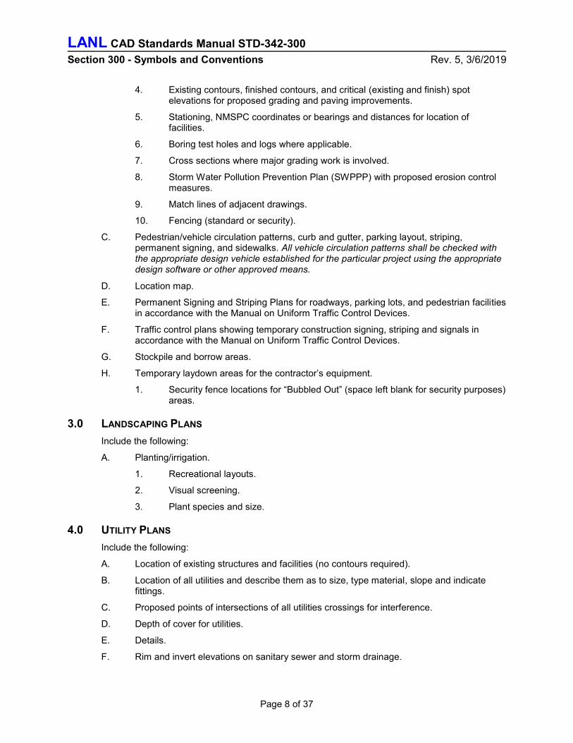
4. Existing contours, finished contours, and critical (existing and finish) spot elevations for proposed grading and paving improvements.
5. Stationing, NMSPC coordinates or bearings and distances for location of facilities.
6. Boring test holes and logs where applicable.
7. Cross sections where major grading work is involved.
8. Storm Water Pollution Prevention Plan (SWPPP) with proposed erosion control measures.
9. Match lines of adjacent drawings.
10. Fencing (standard or security).
C. Pedestrian/vehicle circulation patterns, curb and gutter, parking layout, striping, permanent signing, and sidewalks. All vehicle circulation patterns shall be checked with the appropriate design vehicle established for the particular project using the appropriate design software or other approved means.
D. Location map.
E. Permanent Signing and Striping Plans for roadways, parking lots, and pedestrian facilities in accordance with the Manual on Uniform Traffic Control Devices.
F. Traffic control plans showing temporary construction signing, striping and signals in accordance with the Manual on Uniform Traffic Control Devices.
G. Stockpile and borrow areas.
H. Temporary laydown areas for the contractor’s equipment.
1. Security fence locations for “Bubbled Out” (space left blank for security purposes) areas.
3.0 LANDSCAPING PLANS
Include the following:
A. Planting/irrigation.
1. Recreational layouts.
2. Visual screening.
3. Plant species and size.
4.0 UTILITY PLANS
Include the following:
A. Location of existing structures and facilities (no contours required).
B. Location of all utilities and describe them as to size, type material, slope and indicate fittings.
C. Proposed points of intersections of all utilities crossings for interference.
D. Depth of cover for utilities.
E. Details.
F. Rim and invert elevations on sanitary sewer and storm drainage.

LANL CAD Standards Manual STD-342-300 Section 300 - Symbols and Conventions Rev. 5, 3/6/2019
Page 9 of 37
5.0 ROAD PLANS
Include the following:
A. Geometric plan and profile, pavement markings, surfacing, thickness, cross section, and traffic control devices.
B. Operational plan for vehicular circulation is required showing turnaround movements, ingress and egress.
C. Centerline location, coordinates, or bearing and distances.
D. Stationing.
E. Curve data (show delta (D), radius (R), tangent (T), length (L), chord bearing (CH), point of curvature (PC), point of intersections (PI), and point of tangency (PT).
F. PC and PT stationing.
G. PI coordinates.
H. Typical roadway sections with pavement type and thickness, base and sub-grade materials, cross slopes, and taper details.
I. Drainage culverts, size and type, ditches, and hillside interceptor benches and slopes. Include flowline elevations at culverts and slopes.
J. Utility crossings.
K. Horizontal alignment design parameters.
6.0 ROAD PROFILES
Include the following:
A. Ground line (existing ground at centerline of road).
B. Finished grade (top of finished surface at centerline).
C. Left and right curb profiles (if required).
D. Longitudinal grades in percentages.
E. Elevations at station intervals and vertical curves including: vertical point of curvature (VPC), vertical point of intersection (VPI), and vertical point of tangency (VPT).
F. Elevations along vertical curve and tangents (if required).
G. Vertical alignment design parameters.
H. Drainage culverts & utility crossings.
7.0 ROAD, PARKING LOT, & SITE GRADING CROSS SECTIONS (LOOKING UP-STATION)
Include the following:
A. Stationing, scales, and earthwork requirements.
B. Centerline and/or baseline location.
C. Existing ground line (phantom line type).
D. Finished grade surface and bottom of base course (continuous line type).
E. Annotate cut and fill slopes.
F. Ditch sections and structural features such as drop inlets, culverts, etc.

LANL CAD Standards Manual STD-342-300 Section 300 - Symbols and Conventions Rev. 5, 3/6/2019
Page 10 of 37
8.0 STORM DRAIN PLANS
Include the following:
A. Existing underground structures including size, type, and location. (To be relocated or removed.)
B. Existing storm drains, culverts, inlets, and outfall structures.
C. Existing utilities.
D. New storm drain location (including coordinates, distances, and bearings), stationing, curve data (show D, R, T, L, PC, PI and PT), manholes, transitions, and junction structures.
E. Catch basin locations. (Tie to curb returns or centerline road stationing/offset), type, size,
invert elevations).
F. Pipe length, size, type, pipe slope, and end inverts.
G. Utilities crossings - water, sewer, gas, steam, electric, telephone, etc.
H. Unique trenching, shoring, benching, and/or backfill requirements.
9.0 STORM DRAIN (PROFILE)
Include the following:
A. Ground line (existing ground at centerline of storm drain).
B. Street names, building designations, and existing structures.
C. Existing underground utilities including sizes, types, interferences, and elevations.
D. Centerline stationing, match lines, manholes, structures, design slopes, flow rates, and grade changes.
E. Storm drain slope (ft./ft.), invert elevations, length, size, type of pipe, centerline stationing, direction of connecting pipe inlets, and transition structures.
F. Parallel existing storm drains.
G. Parallel existing utilities.
H. Concrete or other encasement for utility crossings.
I. Details of crossings with existing utilities.
10.0 SANITARY SEWER PLANS
Include the following:
A. Existing underground utilities, size, type, and location.
B. Proposed sewer centerline geometry (coordinates, distances, and bearings), stationing, curve data (show D, R, T, L, PL, PI and PT), manholes (type and all callouts from standard drawings), and sizes.
C. Encasement of sewer.
D. Curbs, driveways, and sidewalks to be removed and replaced.
E. Fire hydrants, valves, meters or other utility appurtenances to be relocated.

LANL CAD Standards Manual STD-342-300 Section 300 - Symbols and Conventions Rev. 5, 3/6/2019
Page 11 of 37
11.0 SANITARY SEWER PROFILES
Include the following:
A. Existing ground line and proposed cover along center line of sewer.
B. Substructures and/or utilities (parallel or crossing) including size, type, rim and invert elevations (excavated and checked, if required).
C. Centerline stationing, match lines, manholes, structures, design slopes, flow capacity, and grade changes.
D. Sewer profile slope and elevations, (ft/ft) and (ft), length, type, and diameter of pipe, centerline stationing, and direction of connecting inlets or Y branches.
E. Parallel existing storm drains.
F. Encasement for sewers.
G. Details of crossings with existing utilities.
12.0 WATER SUPPLY AND DISTRIBUTION
Include the following:
A. Location of all structures and facilities.
B. Location, size and type of domestic water lines, valves, valve pits, meters, etc.
C. Location, size and type of fire water lines, hydrants, post indicator valves, PRV’s, storage tanks, valves, valve boxes, meters, and pits.
D. Coordinates at all angle points of distribution lines.
E. Bearing and distance between PI's.
F. Show existing utilities and structures along alignment.
G. Show section cut including invert elevations at all utility crossings.
H. Horizontal/vertical alignment design parameters.
I. Typical trench sections, bedding, and backfill requirements.
J. Restrained fittings and/or thrust block locations and calculations.
K. Horizontal geometry including curve data, if required, D, R, T, L, PC, PI and PT.
13.0 RADIOACTIVE LIQUID WASTE, CAUSTIC, ACID, AND CHEMICAL PLANS AND PROFILES
Include the following:
A. Existing ground line and proposed cover over the piping.
B. Substructures and/or utilities (parallel or crossing) including size, type, rim and invert elevations (excavated and checked, if required).
C. Piping profile slope and elevations, (ft./ft.) and (ft.), length and type of pipe, size, station size, and direction of connecting inlets or Y branches.
D. Monitoring system instrument and control
E. Location of control valves, type, model number, and access requirements.
F. Centerline stationing, match lines, manholes, structures, design slopes, flow capacity, and grade changes.
G. Encasement for piping.
LANL CAD Standards Manual STD-342-300 Section 300 - Symbols and Conventions Rev. 5, 3/6/2019
Page 12 of 37
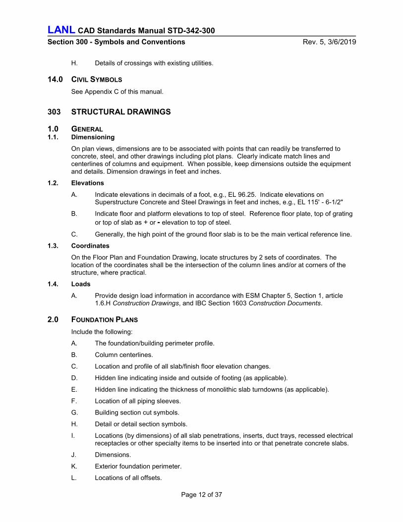
H. Details of crossings with existing utilities.
14.0 CIVIL SYMBOLS
See Appendix C of this manual.
303 STRUCTURAL DRAWINGS
1.0 GENERAL 1.1. Dimensioning
On plan views, dimensions are to be associated with points that can readily be transferred to concrete, steel, and other drawings including plot plans. Clearly indicate match lines and centerlines of columns and equipment. When possible, keep dimensions outside the equipment and details. Dimension drawings in feet and inches.
1.2. Elevations
A. Indicate elevations in decimals of a foot, e.g., EL 96.25. Indicate elevations on Superstructure Concrete and Steel Drawings in feet and inches, e.g., EL 115' - 6-1/2"
B. Indicate floor and platform elevations to top of steel. Reference floor plate, top of grating
or top of slab as + or - elevation to top of steel.
C. Generally, the high point of the ground floor slab is to be the main vertical reference line.
1.3. Coordinates
On the Floor Plan and Foundation Drawing, locate structures by 2 sets of coordinates. The location of the coordinates shall be the intersection of the column lines and/or at corners of the structure, where practical.
1.4. Loads
A. Provide design load information in accordance with ESM Chapter 5, Section 1, article 1.6.H Construction Drawings, and IBC Section 1603 Construction Documents.
2.0 FOUNDATION PLANS
Include the following:
A. The foundation/building perimeter profile.
B. Column centerlines.
C. Location and profile of all slab/finish floor elevation changes.
D. Hidden line indicating inside and outside of footing (as applicable).
E. Hidden line indicating the thickness of monolithic slab turndowns (as applicable).
F. Location of all piping sleeves.
G. Building section cut symbols.
H. Detail or detail section symbols.
I. Locations (by dimensions) of all slab penetrations, inserts, duct trays, recessed electrical receptacles or other specialty items to be inserted into or that penetrate concrete slabs.
J. Dimensions.
K. Exterior foundation perimeter.
L. Locations of all offsets.

LANL CAD Standards Manual STD-342-300 Section 300 - Symbols and Conventions Rev. 5, 3/6/2019
Page 13 of 37
M. Locations of all slab/floor depressions.
N. Expansion joints.
3.0 DESIGNATION OF COLUMN LINES
On the Plot Plan and Foundation Drawings, locate structures by coordinates or orthogonal offsets. The location of the base point coordinate shall be the intersection of the column lines in the northeast corner of the structure, where practical. The column line bearing and offset distance, or coordinate of an alternate column line intersection point shall be designated, see CSM Section 200 (201.5.).
4.0 STRUCTURAL STEEL FRAMING DRAWINGS
Framing Plans and Framing Elevations are schematic drawings. Show the centerlines of steel framing members as solid heavy lines stopping short of the member they frame into. Only show partial outlines of webs, flanges, and legs of members when necessary for clarity.
5.0 STRUCTURAL STEEL SHAPES
Label structural steel construction, per AISC 326, Detailing for Steel Construction.
6.0 REINFORCED CONCRETE
Symbols commonly used on reinforced concrete drawings are:
# To indicate size of deformed bar
Ø Plain rounds
@ Spacing center to center
Direction in which bars extend
Limits of area covered by bars
7.0 REINFORCED CONCRETE DRAWINGS
7.1 General
In general, the drafting practices shown in the SP-066 “ACI Detailing Manual” published by the American Concrete Institute are acceptable.
7.2 Reinforcing
A. Call-out of bars should be in one view where practical.
B. Note bar spacing in inches, and inch marks are not to be used, e.g., #6 @ 18.
C. Detailing of reinforcing is to be in accordance with ACI 318 or ACI 349.
8.0 STRUCTURAL STEEL DRAWINGS
8.1 General
A. The drawings shall be in accordance with AISC 360 and AISC 341.
8.2 Connection Guidance
A. Projects should be shop-welded and field-bolted where possible.

LANL CAD Standards Manual STD-342-300 Section 300 - Symbols and Conventions Rev. 5, 3/6/2019
Page 14 of 37
8.3 Welding
A. Make welding details and notes clear and complete. Provide the size, type, length, and spacing. Draw standard symbols and notations in accordance with the American Welding Society's standards AWS A3.0, “Standard Welding Terms and Definitions”, and AWS A2.4, “Standard Symbols for Welding, Brazing and Nondestructive Examination”.
304 ARCHITECTURAL DRAWINGS
1.0 DRAWING PREPARATION
A. Show all building “plan” drawings at scales, orientation and with a north arrow shown in accordance with Section 200 of this manual.
B. All drawing dimensions are to be in conformance with Section 200 of this Manual.
C. All building elevations are preferably to be drawn in the same scale as the building plan drawings.
D. Indicate main floor as 100’-0” elevation on plan.
E. Where plans involve the addition to, or modification of, an existing structure, the existing structure plans shall be verified as “As-Found” with corresponding building information included.
2.0 LIFE SAFETY/CODE ANALYSIS PLANS
Including but not limited to the following:
A. Occupancy Type and Group.
B. Construction Type.
C. Required separations, if any
D. Maximum exit travel distance allowed and provided.
E. Show exits clearly and indicate number required and provided.
F. Travel paths from furthest distance allowed and provided.
G. Maximum common path of travel distance allowed and provided.
H. Maximum dead end corridor, if any, allowed and provided.
I. Pull station locations.
J. Fire extinguisher and cabinet locations.
K. Emergency phone locations, if any.
L. Plumbing Fixture counts, required and provided.
3.0 DEMOLITION PLANS
Including but not limited to the following:
A. Limits of demolition.
B. Show particulate, noise, and visual barriers as well as pedestrian traffic control barriers.
C. Clearly note all equipment and material being removed or abandoned in place.
D. Show evacuation paths from demolition area.
E. Dimensions as required.

LANL CAD Standards Manual STD-342-300 Section 300 - Symbols and Conventions Rev. 5, 3/6/2019
Page 15 of 37
4.0 FLOOR PLANS
Include the following:
A. Perimeter walls drawn to scale.
B. Column centerlines and exterior building columns.
C. Interior walls drawn to scale.
D. Plumbing fixtures and centerlines.
E. Permanent partitions and walls.
F. Locations of windows and width drawn to scale.
G. Locations of doors with handing, size (width) and type of movement drawn to scale.
H. Building section cut symbols.
I. Detail section cut symbols.
J. Enlarged plan and/or elevation identification symbols.
K. Wall, interior elevation, detail symbols.
L. Room numbers, symbols, and names (in renaming, check with a Derivative Classifier for impact).
M. Cabinetry locations, length and width drawn to scale.
N. Mechanical, electrical, plumbing and fire protection equipment locations and rooms shown.
O. Detail, interior elevation and section symbols shown drawn as per the requirements of this manual.
P. Areas of enlarged plan views shall be identified and referenced.
Q. Finished floor elevation.
R. Overhead soffits and suspended equipment.
S. Dimensions.
T. Overall building with building additions to include existing building.
U. Building offsets.
V. Interior fixtures not dimensioned elsewhere.
W. Sleeves in cast-in-place concrete walls.
X. Door number symbols.
Y. Window type symbols.
Z. Wall type symbols.
AA. Floor drains.
BB. Fire extinguisher cabinets.
CC. Housekeeping pads.
DD. Equipment (stoves, sinks, tables, etc.)
EE. Stairs and railings with arrows indicating direction of up and down.
FF. Ramps and railings with arrows indicating direction of slope.
GG. Raised or recessed floor areas.

LANL CAD Standards Manual STD-342-300 Section 300 - Symbols and Conventions Rev. 5, 3/6/2019
Page 16 of 37
HH. Toilet partitions.
II. Fire walls and rating (see Fire Protection section 308 and Symbols (Appendix D-1) of this Section.
5.0 FLOOR FINISH PLANS
Including but not limited to the following:
A. Show patterns of floor finishes.
B. Dimensions as required.
C. Ramps, stairs, raised floor, and recessed floor areas.
D. Housekeeping pads.
E. Walls, columns, and toilet partitions.
F. Section and detail cuts.
G. Room names and numbers.
H. Notes as required.
6.0 REFLECTED CEILING PLANS
Including but not limited to the following:
A. Show all ceiling finishes.
B. All exposed structural materials.
C. Layout of light fixtures.
D. Direction and pattern of suspended ceiling.
E. Finished ceiling elevations.
F. Dimensions as required.
G. Soffits and chases.
H. Sklylights.
I. Section and detail cuts.
J. Room names and numbers.
K. Notes as required.
7.0 ROOF PLANS FOR CONSTRUCTION
Including but not limited to the following:
A. Show access areas.
B. Overall dimensions.
C. Roof type (construction type).
D. Show slope direction and magnitude.
E. Pitch.
F. Roof drains.
G. Overhangs with dimensions.
H. Penetrations and type (plumbing, HVAC, etc.)
LANL CAD Standards Manual STD-342-300 Section 300 - Symbols and Conventions Rev. 5, 3/6/2019
Page 17 of 37
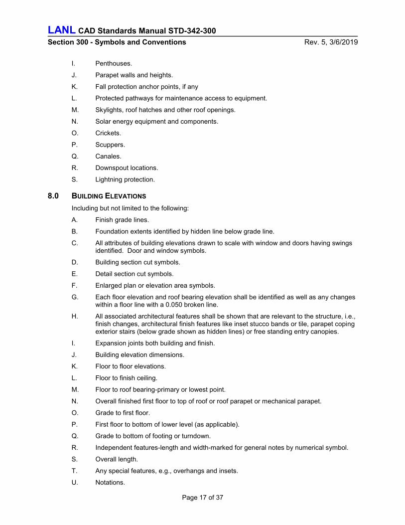
I. Penthouses.
J. Parapet walls and heights.
K. Fall protection anchor points, if any
L. Protected pathways for maintenance access to equipment.
M. Skylights, roof hatches and other roof openings.
N. Solar energy equipment and components.
O. Crickets.
P. Scuppers.
Q. Canales.
R. Downspout locations.
S. Lightning protection.
8.0 BUILDING ELEVATIONS
Including but not limited to the following:
A. Finish grade lines.
B. Foundation extents identified by hidden line below grade line.
C. All attributes of building elevations drawn to scale with window and doors having swings identified. Door and window symbols.
D. Building section cut symbols.
E. Detail section cut symbols.
F. Enlarged plan or elevation area symbols.
G. Each floor elevation and roof bearing elevation shall be identified as well as any changes within a floor line with a 0.050 broken line.
H. All associated architectural features shall be shown that are relevant to the structure, i.e., finish changes, architectural finish features like inset stucco bands or tile, parapet coping exterior stairs (below grade shown as hidden lines) or free standing entry canopies.
I. Expansion joints both building and finish.
J. Building elevation dimensions.
K. Floor to floor elevations.
L. Floor to finish ceiling.
M. Floor to roof bearing-primary or lowest point.
N. Overall finished first floor to top of roof or roof parapet or mechanical parapet.
O. Grade to first floor.
P. First floor to bottom of lower level (as applicable).
Q. Grade to bottom of footing or turndown.
R. Independent features-length and width-marked for general notes by numerical symbol.
S. Overall length.
T. Any special features, e.g., overhangs and insets.
U. Notations.

LANL CAD Standards Manual STD-342-300 Section 300 - Symbols and Conventions Rev. 5, 3/6/2019
Page 18 of 37
V. Materials and types.
W. Special identifications.
X. Height elevations of window sills.
Y. Horizontal dimensions as required.
9.0 BUILDING SECTIONS
Include the following:
A. Drawn to minimum scale of 1/4” = 1’ 0” preferably 3/8” = 1’ 0”
B. All sectioned architectural / structural building systems and large components shown.
C. All background architectural elevation features shown (interior elements).
D. Primary systems materials section symbols shown.
E. Vertical dimensions.
F. Foundation to floor dimensions.
G. Floor to floor dimensions.
H. Floor system thickness.
I. Primary bearing heights.
J. Elements not vertically dimensioned elsewhere.
K. Notations & Symbols.
L. System or component call-outs.
M. Circled and referenced to enlarged detail as required.
10.0 ENLARGED DETAILS AND PLANS
Include the following:
A. Material Detailed information that cannot be accommodated on a smaller scaled drawing.
B. Materials or components sectioned to show materials symbolically.
C. Components shown are sized and located to scale.
D. Background components or features.
E. All materials and components are to be noted and, where applicable, notations shall include height above grade as in plan view.
11.0 FLOOR PLANS OF RECORD (FPR)
11.1 General Guidance
A. FPR are used as a technical baseline drawing for Infrastructure Planning, Facility Planning, Space Utilization, Emergency Response, Emergency Evacuation Plans, Interior Design, As-Built Record Floor Plans, and Information drawings for outside Architects/Engineers for the development of construction drawings to existing facilities, geo-spatial information for Geographic Information Systems, and Title II design. (See §101.3.D, “Reference Drawings: General Definitions”)
11.2 Usage
A. FPRs are not intended for use as construction drawings. FPRs are used as a baseline drawing for conducting and developing the following:

LANL CAD Standards Manual STD-342-300 Section 300 - Symbols and Conventions Rev. 5, 3/6/2019
Page 19 of 37
1. Infrastructure Planning.
2. Facility Planning.
3. Space Utilization.
4. Emergency Response.
5. Emergency Evacuation Diagrams.
6. Interior design including systems furniture.
7. As-Built Record Floor Plans.
8. Information drawings for outside Architects/Engineers for the development of construction drawings to existing facilities.
9. Geo-spatial information for Geographic Information Systems.
11.3 Classification of Drawings
A. Classification:
1. All drawings shall be submitted to a LANL Derivative Classifier/Reviewing Official (DC/RO) for determination prior to official release.
11.4 Verification of Accuracy
A. New and existing facilities:
1. All FPRs may be reviewed and verified for accuracy through the FPR Design Review process (contact Infrastructure Planning – Space Management & Facility Planning).
11.5 Types of FPRs
A. New Facility:
1. The FPR for a new facility shall be based on the As-Built Construction documents developed by the Subcontractor of the new facility.
a. If no As-Built drawings are available, the new facility shall be field validated to an As-Found condition.
B. New Addition (or modification) to existing facility:
1. The FPR for the addition or remodel of an existing facility shall be based on the construction documents developed by the contractor of the work.
2. After construction is complete and As-Built Construction documents are available, the new addition or remodel shall be field validated to its As-Found condition by using the Infrastructure Planning validation process.
3. Generate the FPR in accordance with this manual. This is to include modifications to buildings including room numbering, structure, room and wall configuration, and door and window removal/relocation.
C. Existing facility with no FPR:
1. Field-validate the As-Found conditions of the facility using Facility Planning and space validation processes.
2. Generate drawings in accordance with this manual.
D. Existing facility with current FPR:
1. Revise the existing FPR in accordance with this manual.
11.6 Format
A. Drafting:
LANL CAD Standards Manual STD-342-300 Section 300 - Symbols and Conventions Rev. 5, 3/6/2019
Page 20 of 37
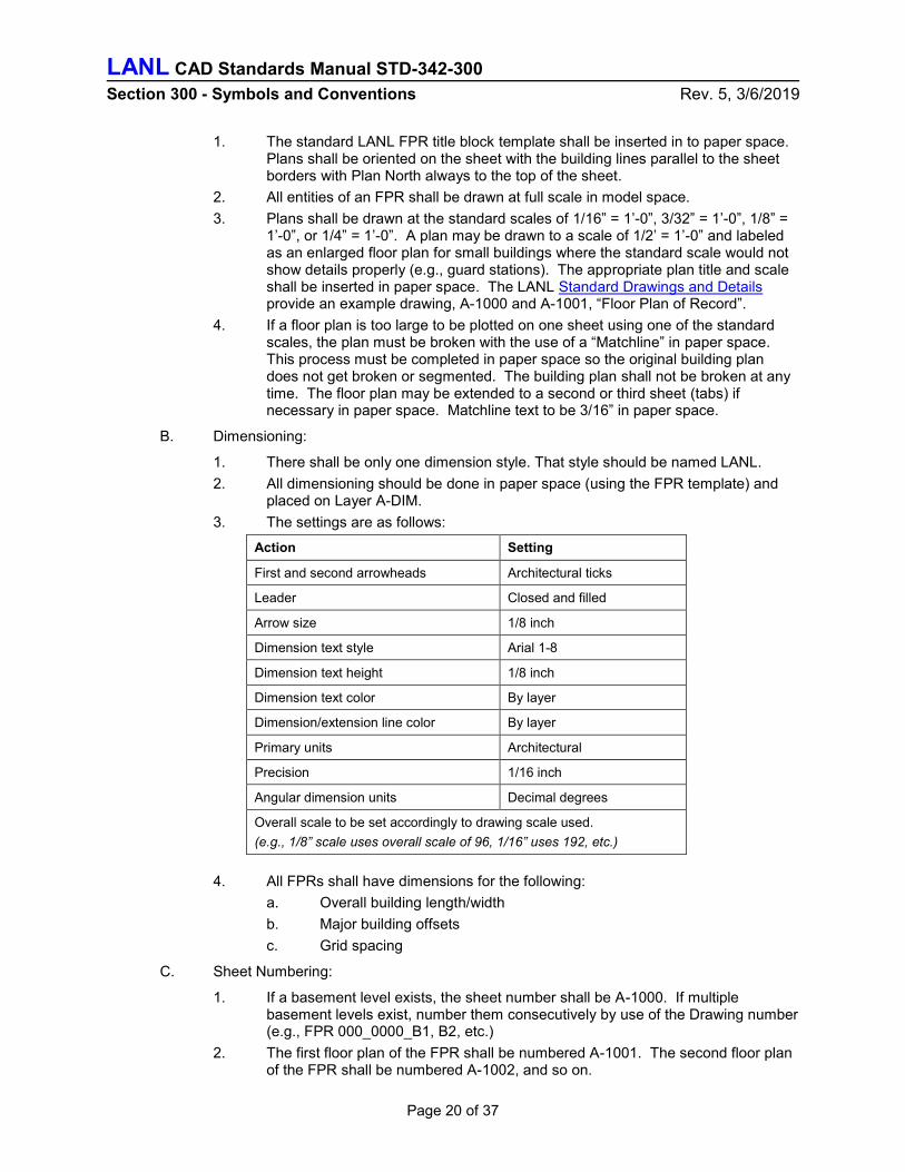
1. The standard LANL FPR title block template shall be inserted in to paper space. Plans shall be oriented on the sheet with the building lines parallel to the sheet borders with Plan North always to the top of the sheet.
2. All entities of an FPR shall be drawn at full scale in model space.
3. Plans shall be drawn at the standard scales of 1/16” = 1’-0”, 3/32” = 1’-0”, 1/8” = 1’-0”, or 1/4” = 1’-0”. A plan may be drawn to a scale of 1/2’ = 1’-0” and labeled as an enlarged floor plan for small buildings where the standard scale would not show details properly (e.g., guard stations). The appropriate plan title and scale shall be inserted in paper space. The LANL Standard Drawings and Details provide an example drawing, A-1000 and A-1001, “Floor Plan of Record”.
4. If a floor plan is too large to be plotted on one sheet using one of the standard scales, the plan must be broken with the use of a “Matchline” in paper space. This process must be completed in paper space so the original building plan does not get broken or segmented. The building plan shall not be broken at any time. The floor plan may be extended to a second or third sheet (tabs) if necessary in paper space. Matchline text to be 3/16” in paper space.
B. Dimensioning:
1. There shall be only one dimension style. That style should be named LANL.
2. All dimensioning should be done in paper space (using the FPR template) and placed on Layer A-DIM.
3. The settings are as follows:
Action Setting
First and second arrowheads Architectural ticks
Leader Closed and filled
Arrow size 1/8 inch
Dimension text style Arial 1-8
Dimension text height 1/8 inch
Dimension text color By layer
Dimension/extension line color By layer
Primary units Architectural
Precision 1/16 inch
Angular dimension units Decimal degrees
Overall scale to be set accordingly to drawing scale used.
(e.g., 1/8” scale uses overall scale of 96, 1/16” uses 192, etc.)
4. All FPRs shall have dimensions for the following:
a. Overall building length/width
b. Major building offsets
c. Grid spacing
C. Sheet Numbering:
1. If a basement level exists, the sheet number shall be A-1000. If multiple basement levels exist, number them consecutively by use of the Drawing number (e.g., FPR 000_0000_B1, B2, etc.)
2. The first floor plan of the FPR shall be numbered A-1001. The second floor plan of the FPR shall be numbered A-1002, and so on.

LANL CAD Standards Manual STD-342-300 Section 300 - Symbols and Conventions Rev. 5, 3/6/2019
Page 21 of 37
3. If it is necessary to break up the building into two or more sections with matchlines, the drawing numbering and tab numbering shall be assigned as follows:
a. B1.1 – Basement level one (first section)
b. B1.2 –Basement level one (second section)
c. B2.1 – Sub Basement (first section)
d. B2.2 – Sub Basement (second section)
e. First floor (first section)
f. First floor (second section)
g. 02.1 – Second floor (first section)
h. 02.2 – Second floor (second section)
D. Drawing Electronic File Convention:
1. All FPR drawing files shall be named as follows:
[Floor Plan of Record]_[Technical Area]_[Building Number]_[Floor]
Example: FPR_03_0410_01
E. Grid References:
1. Grids shall match that of the original construction documents.
2. Column Line designations shall be shown on all sides of drawing as follows:
a. Horizontally, by letter, starting with “A” (from left to right).
b. Vertically, by number, starting with “1” (from top to bottom).
c. Letters ‘I’ and ‘O’ shall not be used.
3. The column grid lines shall extend through the entire drawing to the corresponding bubble.
4. FPR symbols and text shall be in accordance with the following standards:
a. Grid bubble size of 1/2” diameter, 0.40 mm line width
b. The grid line shall be a line type of “CENTER”, having line width of 0.18 mm.
c. The grid line shall be color 13.
d. The grid designator text shall be 1/4 inch high.
e. The grid bubble must be attribute.
F. Font Styles and Text Size Requirements:
1. Notes and all other text shall use the style named “Arial x-x” or Arial Black “x-x” using an Arial or Arial Black font. (Unless otherwise specified in this manual)
2. Text shall be 1/8” high minimum (including dimensions).
G. Text used for dimensioning shall be in the “Arial x-x” text style, and shall be minimum 1/8” text height.
H. Text shall be oriented so that it reads horizontally from left to right and/or vertically from bottom to top.
I. Only the following text styles shall be used in any FPR drawing (all other styles must be purged from the drawing):
1. Arial x-x
2. Arial Black x-x

LANL CAD Standards Manual STD-342-300 Section 300 - Symbols and Conventions Rev. 5, 3/6/2019
Page 22 of 37
3. Swis721 Blk BT (for title block logo)
4. Standard
J. Font width factor shall be 1.0 for all text
K. Line Weights:
1. All layers shall be given one of the following line weights (See layer table 304-1 for assignments):
a. 0.18 mm
b. 0.25 mm
c. 0.35 mm
d. 0.40 mm
e. 0.70 mm
f. 0.80 mm (matchline only)
11.7 Polylines Guidelines
A. The “GROS” layer will show the total constructed area of a building. Polylines are to be drawn in accordance with the standard method for measuring floor area in office buildings as outlined in ANSI/BOMA Z65.1 (2010 or later, with LANL-specific adaptations).
B. The “RM” layer will show usable area and all common areas. Polylines are constructed per ANSI/BOMA Z65.1, and shall outline the following areas:
1. All building common areas
2. Building service areas
3. Building amenity areas
4. Major vertical penetrations
5. Utility space
6. Office areas
C. Polylines are to be in accordance with FPR update and Archibus linking process by Space Management and Facility Planning.
11.8 Required Plan Elements
A. Exterior and interior wall construction type, thickness, and room number.
B. Retaining walls and thickness attached to building.
C. Columns and column center lines (Grid lines and numbers).
D. Permanent walls (rooms, hallways, corridors and vestibules) with room numbers.
E. Doors and door swing.
F. Windows – operable configuration addressed per keyed notes.
G. Wall openings that allow passage from one room to another and start at the floor line.
H. Stairways and attached handrails (include stair room number) (show direction of travel – up or down).
I. Utility chases.
J. Exterior wall louvers.
K. Pads at exterior door (concrete and wood).
L. Interior and exterior ramps. Show direction of slope, handrails, and curbs as required by code.
LANL CAD Standards Manual STD-342-300 Section 300 - Symbols and Conventions Rev. 5, 3/6/2019
Page 23 of 37
M. Attached docks and canopies.
N. Ladders – both interior and exterior.
O. Elevators and elevator numbers.
P. Built-in millwork and attached equipment.
Q. Floor pits, trenches, and numbers.
R. Toilet room partitions and fixtures (plumbing etc.).
S. Overall building dimensions, wall thickness, and outside landing/dock dimensions.
T. Mezzanines and room numbers.
U. Fire wall location and identified with symbols per Appendix D-1 and D-2 (Fire Protection symbols).
V. Raised or recessed floor areas.
W. Systems furniture offices and cubicles.
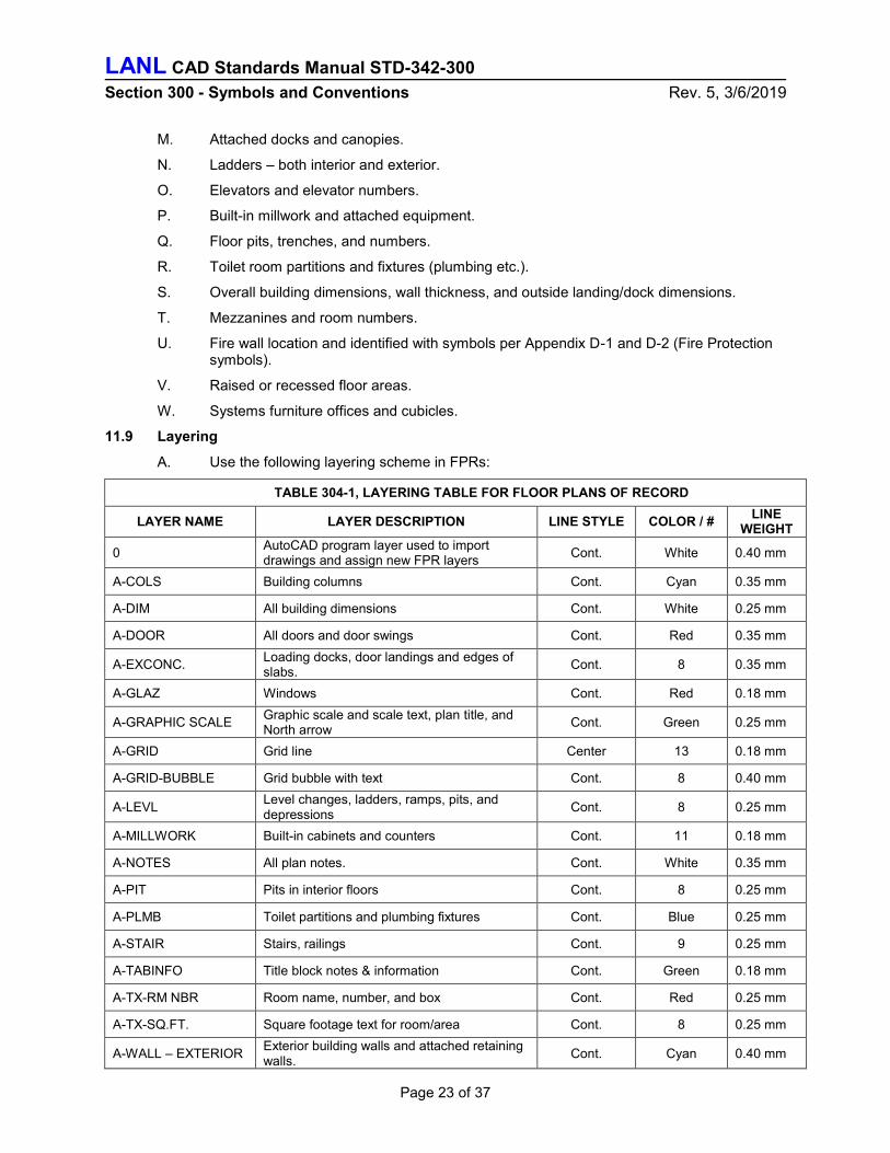
11.9 Layering
A. Use the following layering scheme in FPRs:
TABLE 304-1, LAYERING TABLE FOR FLOOR PLANS OF RECORD
LAYER NAME LAYER DESCRIPTION LINE STYLE COLOR / # LINE
WEIGHT
0 AutoCAD program layer used to import drawings and assign new FPR layers
Cont. White 0.40 mm
A-COLS Building columns Cont. Cyan 0.35 mm
A-DIM All building dimensions Cont. White 0.25 mm
A-DOOR All doors and door swings Cont. Red 0.35 mm
A-EXCONC. Loading docks, door landings and edges of slabs.
Cont. 8 0.35 mm
A-GLAZ Windows Cont. Red 0.18 mm
A-GRAPHIC SCALE Graphic scale and scale text, plan title, and North arrow
Cont. Green 0.25 mm
A-GRID Grid line Center 13 0.18 mm
A-GRID-BUBBLE Grid bubble with text Cont. 8 0.40 mm
A-LEVL Level changes, ladders, ramps, pits, and depressions
Cont. 8 0.25 mm
A-MILLWORK Built-in cabinets and counters Cont. 11 0.18 mm
A-NOTES All plan notes. Cont. White 0.35 mm
A-PIT Pits in interior floors Cont. 8 0.25 mm
A-PLMB Toilet partitions and plumbing fixtures Cont. Blue 0.25 mm
A-STAIR Stairs, railings Cont. 9 0.25 mm
A-TABINFO Title block notes & information Cont. Green 0.18 mm
A-TX-RM NBR Room name, number, and box Cont. Red 0.25 mm
A-TX-SQ.FT. Square footage text for room/area Cont. 8 0.25 mm
A-WALL – EXTERIOR Exterior building walls and attached retaining walls.
Cont. Cyan 0.40 mm
LANL CAD Standards Manual STD-342-300 Section 300 - Symbols and Conventions Rev. 5, 3/6/2019
Page 24 of 37
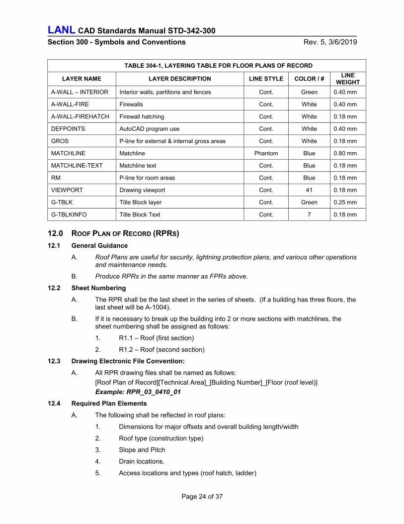
TABLE 304-1, LAYERING TABLE FOR FLOOR PLANS OF RECORD
LAYER NAME LAYER DESCRIPTION LINE STYLE COLOR / # LINE
WEIGHT
A-WALL – INTERIOR Interior walls, partitions and fences Cont. Green 0.40 mm
A-WALL-FIRE Firewalls Cont. White 0.40 mm
A-WALL-FIREHATCH Firewall hatching Cont. White 0.18 mm
DEFPOINTS AutoCAD program use Cont. White 0.40 mm
GROS P-line for external & internal gross areas Cont. White 0.18 mm
MATCHLINE Matchline Phantom Blue 0.80 mm
MATCHLINE-TEXT Matchline text Cont. Blue 0.18 mm
RM P-line for room areas Cont. Blue 0.18 mm
VIEWPORT Drawing viewport Cont. 41 0.18 mm
G-TBLK Title Block layer Cont. Green 0.25 mm
G-TBLKINFO Title Block Text Cont. 7 0.18 mm
12.0 ROOF PLAN OF RECORD (RPRS)
12.1 General Guidance
A. Roof Plans are useful for security, lightning protection plans, and various other operations and maintenance needs.
B. Produce RPRs in the same manner as FPRs above.
12.2 Sheet Numbering
A. The RPR shall be the last sheet in the series of sheets. (If a building has three floors, the last sheet will be A-1004).
B. If it is necessary to break up the building into 2 or more sections with matchlines, the sheet numbering shall be assigned as follows:
1. R1.1 – Roof (first section)
2. R1.2 – Roof (second section)
12.3 Drawing Electronic File Convention:
A. All RPR drawing files shall be named as follows:
[Roof Plan of Record][Technical Area]_[Building Number]_[Floor (roof level)]
Example: RPR_03_0410_01
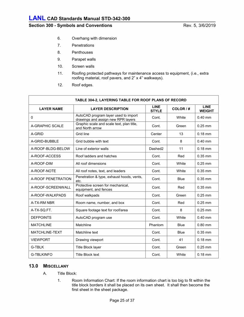
12.4 Required Plan Elements
A. The following shall be reflected in roof plans:
1. Dimensions for major offsets and overall building length/width
2. Roof type (construction type)
3. Slope and Pitch
4. Drain locations.
5. Access locations and types (roof hatch, ladder)
LANL CAD Standards Manual STD-342-300 Section 300 - Symbols and Conventions Rev. 5, 3/6/2019
Page 25 of 37
6. Overhang with dimension
7. Penetrations
8. Penthouses
9. Parapet walls
10. Screen walls
11. Roofing protected pathways for maintenance access to equipment, (i.e., extra roofing material, roof pavers, and 2” x 4” walkways).
12. Roof edges.
TABLE 304-2, LAYERING TABLE FOR ROOF PLANS OF RECORD
LAYER NAME LAYER DESCRIPTION LINE
STYLE COLOR / #
LINE WEIGHT
0 AutoCAD program layer used to import drawings and assign new RPR layers
Cont. White 0.40 mm
A-GRAPHIC SCALE Graphic scale and scale text, plan title, and North arrow
Cont. Green 0.25 mm
A-GRID Grid line Center 13 0.18 mm
A-GRID-BUBBLE Grid bubble with text Cont. 8 0.40 mm
A-ROOF-BLDG-BELOW Line of exterior walls Dashed2 11 0.18 mm
A-ROOF-ACCESS Roof ladders and hatches Cont. Red 0.35 mm
A-ROOF-DIM All roof dimensions Cont. White 0.25 mm
A-ROOF-NOTE All roof notes, text, and leaders Cont. White 0.35 mm
A-ROOF PENETRATION Penetration & type, exhaust hoods, vents, etc.
Cont. Blue 0.35 mm
A-ROOF-SCREENWALL Protective screen for mechanical, equipment, and fences
Cont. Red 0.35 mm
A-ROOF-WALKPADS Roof walkpads Cont. Green 0.25 mm
A-TX-RM NBR Room name, number, and box Cont. Red 0.25 mm
A-TX-SQ.FT. Square footage text for roof/area Cont. 8 0.25 mm
DEFPOINTS AutoCAD program use Cont. White 0.40 mm
MATCHLINE Matchline Phantom Blue 0.80 mm
MATCHLINE-TEXT Matchline text Cont. Blue 0.35 mm
VIEWPORT Drawing viewport Cont. 41 0.18 mm
G-TBLK Title Block layer Cont. Green 0.25 mm
G-TBLKINFO Title Block text Cont. White 0.18 mm
13.0 MISCELLANY
A. Title Block:
1. Room Information Chart: If the room information chart is too big to fit within the title block borders it shall be placed on its own sheet. It shall then become the first sheet in the sheet package.

LANL CAD Standards Manual STD-342-300 Section 300 - Symbols and Conventions Rev. 5, 3/6/2019
Page 26 of 37
B. Key Plan:
1. If the building must be broken using matchlines, then a key plan is required that reflects which portion of the building is shown on any given sheet.
a. Key plans shall be located at the upper right corner of the title block, and shall utilize a 3 inch by 5 inch area.
b. A corresponding Title Bar shall be associated with each key plan. It shall be entitled “Key Plan”, contain a North arrow, and shall specify that the key plan doesn’t conform to a scale by notating “No Scale”.
c. Key Plans and FPR drawings shall be oriented identically.
C. Title Block Usage:
1. LANL FPR title blocks should be used for internal use only. If the drawing file should be sent to external recipients, the LANL FPR title block should be removed from the drawing file.
14.0 EMERGENCY EVACUATION DIAGRAMS (EED) 2
A. Use the most current floor plan of record (FPR) to generate an emergency evacuation diagram.
B. Verify accuracy of FPR prior to generating EED. Correct deficiencies in FPR and submit the corrected FPR to Space Management and Facility Planning to be incorporated into the Archibus system (LANL internal).
C. Evacuation route diagrams shall include the following:3
1. Fire extinguisher locations
2. Fire alarm/pull station locations
3. Evacuation routes (primary in Green, continuous line type with flow arrows, secondary route when applicable in Red, dashed line type).4
4. Assembly area locations (Primary and Secondary as required) (Coordinated by Security and Emergency Operations).
5. Legend of symbols.
6. Exit sign locations
7. “YOU ARE HERE” notation with a solid red circle 1/4 inch in diameter.
8. Shelter In Place locations
9. Emergency telephone (special applications only)
10. Handicap access
11. No exit (special applications only)
D. EEDs shall:
1. Be drawn to scale and must be legible – stories are to be broken up into evacuation areas when necessary however they may be shown on a single sheet per story if legible.
2 ASTM E-2238-12 Standard Guide for Evacuation Route Diagrams as modified by LANL SEO, FP-DO authorities and applicable codes requirements.
3 This list is minimum requirements and is sufficient for most cases. Certain customers may request additional items (such as AED locations) and these can be accommodated. The legend shown on an EED must be edited for the specific application as needed. 4 Primary and secondary evacuation routes/assembly areas are special applications; certain locations at LANL have different routes/assembly areas for specific reasons, such as separation of Anti-C personnel from Non Anti-C personnel (e.g., PF-4) or different routes/assembly areas due to prevailing wind direction at time of the emergency (e.g., RLW). These are not often used and primary routes are the minimum; judgement must be used and the secondary routes/assembly areas should be deleted from the legend if not used.

LANL CAD Standards Manual STD-342-300 Section 300 - Symbols and Conventions Rev. 5, 3/6/2019
Page 27 of 37
2. Be drawn on “D” size paper, plotted on ANSI C (17” x 22”) paper in landscape orientation and laminated/framed per LANL’s picture framing Just-In-Time (JIT) subcontractor criteria.
3. Show orientation that coincides with the orientation of the viewer.
15.0 ARCHITECTURAL SYMBOLS
A. Symbols used in preparation of Architectural drawings are to comply with the National CAD Standards.
B. Also, use the National CAD Standards symbols for:
1. Materials and surfaces in Large scale section and Graphic representation.
2. Materials and surfaces in Small scale Plan Views and Graphic representation.
305 FIRE PROTECTION DRAWINGS
1.0 DRAWING DESIGN PREPARATION
A. Draw to scale and show north arrow symbol. Show dimensions, including elevations in feet and decimals of a foot.
B. Include on drawings, plans and site plans existing features such as buildings, roads, walks, parking areas, large trees, underground and overhead utilities, valve boxes, water meters, fire hydrants, pressure reducing valves, backflow preventers, thrust blocks, valve pits, and other features pertinent to the specific project.
C. The types of plans required for preparing a fire protection drawing set include floor plans, reflected ceiling plans, elevations, sections, isometrics, schematics and schedules. Reflected ceiling plans should show locations of lights, diffusers and other devices installed at the ceiling. Related plans should show ductwork layout. Include within each set of drawings all symbols, legends, and notes needed to understand everything shown on the drawings. See 2.0 below.
D. The information to be shown on the working plans for installing fire protection systems is listed in 3.0 through 7.0 below. Related information that is normally handled in other drawing sets is listed in 8.0 below.
E. Support the information shown on the drawings with a detailed Bills of Materials listing numbers and types of all devices provided. The Bill of Materials can be incorporated on the drawings or can be separate. It should match the manufacturers’ literature submitted for the project.
F. Fire protection project drawings include those showing building structural features, emergency lighting, fire alarm systems, special extinguishing systems, sprinkler systems, and fire protection water supplies. For some projects, other types of drawings could be included.
G. Fire protection symbols (Appendix D) are per NFPA 170.
2.0 BUILDING ARCHITECTURAL AND STRUCTURAL FEATURES
A. Show in plans the building architectural and structural features relating to fire and explosion resistance. These features include, but are not limited to:
1. Location of fire barriers (walls/floors/ceilings)
2. Material, thickness, and rating of fire barriers
3. Location and height of parapets
4. Roof construction
5. Rated fire doors/hatches
6. Penetrations of fire barriers and any protection provided for those penetrations

LANL CAD Standards Manual STD-342-300 Section 300 - Symbols and Conventions Rev. 5, 3/6/2019
Page 28 of 37
7. Fire- or explosion-resistant construction details including fireproofing on structural members
8. Location, construction, and size of concealed spaces, attics, closets, bathrooms, and other small enclosures
9. Locations and heights of unrated walls and partitions
B. Some of these features will need to be coordinated with Site, Structural, and Architectural drawings. Some of these features will also need to be shown on the drawings for Sprinklers, Egress Routes, and Special Extinguishing Systems.
3.0 EMERGENCY LIGHTING
A. Include in plans for emergency lighting all the elements required by NFPA 101. Plans should cover the following:
1. Type of lighting provided
2. Location of lights
3. Conduit routing
4. Dedicated outlets
5. Wiring schematic
6. Type of back-up power provided
4.0 FIRE ALARM SYSTEMS
A. The fire alarm system designer should prepare working plans that show the features required by NFPA 72. Drawing requirements for fire alarm systems are identified in the LANL Master Specification for fire alarm systems and include:
1. Locations and types of all fire detectors (heat, smoke, flame, gas detection, etc.).
2. Locations of manual pull stations.
3. Location and type of fire alarm panel and auxiliary panels.
4. Locations of notification appliances.
5. Candela rating of visible notification appliances.
6. Locations and types of remote annunciators and graphics interfaces.
7. Fire alarm zone schedules, designations and descriptions.
8. Conduit type and routing.
9. Fire alarm riser diagram.
10. Point-to-point wiring schematics between the panel and all devices.
11. Device addresses.
12. Location of walls, partitions, sound attenuation materials, and other building construction features that affect placement of fire alarm system components.
13. Sprinkler and special extinguishing system points to be monitored (water flow switches, water pressure switches, special agent discharge, valve tamper, etc.).
14. Air handling plenums with smoke detection/shutdown.
15. Components interlocked with the fire alarm system, such as elevators, dampers, fire doors, smoke doors, special extinguishing systems.
16. Sequence of operation logic diagram or narrative description.
17. Battery calculations.
5.0 SPECIAL EXTINGUISHING SYSTEMS
A. Special extinguishing systems include both water– and non-water–based systems arranged specifically to protect a particular hazard. These systems include:

LANL CAD Standards Manual STD-342-300 Section 300 - Symbols and Conventions Rev. 5, 3/6/2019
Page 29 of 37
1. Clean agent
2. CO2 (not an agent typically utilized at LANL)
3. Deluge
4. Dry chemical
5. Foam
6. Foam-Water
7. Preaction
B. The special extinguishing system designer should prepare working plans that show the features described in the appropriate NFPA codes, including NFPA 11, NFPA 11A, NFPA 12, NFPA 15, NFPA 16, NFPA 17, NFPA 17A, NFPA 18, and NFPA 2001. Include in the plans all structural details that could have an effect on nozzle positioning. This would include the geometry of the room and the hazard being protected.
C. Include complete information on the detection systems, including types of detectors, locations of detectors, and control logic for alarm and agent release. Also include wiring schematics and calculations for battery back-up power. Calculations for the extinguishing agent itself are usually prepared separately from the plans.
6.0 SPRINKLER SYSTEMS
A. The sprinkler system designer should prepare working plans that show the features required by NFPA 13. When inside standpipes and/or hose connections are included in the project, also include the relevant information from NFPA 14.
B. Drawing requirements for sprinkler systems are identified in the LANL Master Specifications for sprinkler systems and include:
1. Sprinkler head information: makes, models, manufacturer, date of manufacture, type, temperature rating, K-factor, RTI, pendent/upright/sidewall, etc.
2. Sprinkler head locations.
3. Number of each type of sprinkler, number of sprinklers per floor, and total number of sprinklers.
4. Pipe type, sizes, lengths, and locations.
5. Dimensions between sprinkler heads, between branch lines, and from end sprinkler heads to the nearest wall(s).
6. Types, sizes and locations of all fittings.
7. Locations of low point drains.
8. Types, sizes, and locations of all valves, including control (shut-off) valves, alarm check valves, dry pipe valves, backflow preventers, etc.
9. Point of connection to existing sprinkler systems.
10. Locations of hydrants and fire department connections.
11. All auxiliary piping and trim, including piping to water motor gongs, and all drains and inspector’s test connections.
12. Capacity in gallons of dry pipe systems.
13. Pitch of all piping for dry systems.
14. Hydraulic design, hydraulic reference points, outline of the calculated areas, and hydraulic demands for nameplate data. (Sprinkler hydraulic calculations are usually prepared separately from the plans.)
15. Locations of water flow alarms and valve tamper devices
16. Locations of hose connections and standpipes
17. Elevations of pipes and sprinklers above finished floor

LANL CAD Standards Manual STD-342-300 Section 300 - Symbols and Conventions Rev. 5, 3/6/2019
Page 30 of 37
18. Earthquake bracing (Seismic calculations are usually prepared separately from the plans.)
C. Include in the plans all structural details that could have an effect on sprinkler head positioning. This would include, but not be limited to, beams, drop ceilings, soffits, full- and partial-height partitions, and any other potential obstructions to sprinkler discharge. Show structural details in elevation or isometric view, or on plan views with elevations called out.
7.0 WATER SUPPLIES
A. Incorporate in plans for fire protection water supplies the information from the appropriate NFPA codes, including NFPA 13, NFPA 14, NFPA 20, NFPA 22, and NFPA 24. Include plans for the following:
1. Underground Mains in streets and at facility
2. Pumps
3. Tanks
4. Hydrants
5. Control and sectional valves.
8.0 OTHER SYSTEMS
A. Life safety analysis, including egress routing and determination of travel distances, shall normally be shown in the Architectural drawing set.
B. Fire and smoke dampers for building HVAC systems, access doors to HVAC dampers, ventilation systems for areas containing vapors, and smoke control systems shall normally be shown in the Mechanical drawing set. Fuel-fired equipment shall also be in the Mechanical set.
C. Emergency lighting is normally shown in the electrical lighting drawing(s).
D. Lightning protection, building and process back-up power systems, and electrical equipment for hazardous areas shall normally be shown in the Electrical drawing set.
E. Process Safety Controls, including P&IDs, shall normally be shown in the Instrumentation and Controls drawing set.
306 PLUMBING DRAWINGS
1.0 GENERAL
A. Water distribution and waste/vent disposal systems shall be shown on the same plan as they occur servicing the fixtures on the floor represented.
B. Waste lines shall be drawn – continuous line type, 0.8 mm.
C. Vent lines shall be drawn – dashed line type, 0.35 mm.
D. All line types on plumbing systems shall have breaks indicating the type of systems (e.g., - RD -, - S -, - CA -, -- V --, etc.)

LANL CAD Standards Manual STD-342-300 Section 300 - Symbols and Conventions Rev. 5, 3/6/2019
Page 31 of 37
2.0 PLUMBING SYSTEMS5
A. Plumbing systems are comprised of:
1. Water: potable, non-potable, grey, soft, distilled, deionized, chilled drinking fountain, make-up.
2. Compressed Air 6
3. Natural Gas
4. Waste: sanitary, roof drain, overflow roof drain, septic, indirect drains, acid, industrial
5. Fuel oil
6. Petroleum
7. Vacuum
8. Steam and Condensate
9. Vent
Note: Some systems listed above that are connected to plumbing equipment may require interface coordination with other disciplines. These interfaces may need to be reflected in System Design Descriptions (SDD), if applicable.
3.0 ISOMETRICS AND SCHEMATICS
A. Isometrics and schematics shall depict the following:
1. Pipe size
2. Pipe material
3. Direction of flow
4. System type (V=vent, S=sanitary waste, etc.)
5. Equipment/fixture identifier
6. Room numbers where equipment/fixture is located
7. Location of piping by keyed note
8. Access panels
9. Slope with pitch arrow including fall expressed in fraction-of-an-inch per foot length of pipe (on main runs)
B. Isometrics shall appear in the P-9000 series, schematics/diagrams in the P-6000 series.
C. Isometrics/diagrams for new systems shall show the entire system layout. Several systems may appear on the same sheet.
D. Plumbing equipment schedules shall appear in the P-7000 series.
E. Plumbing fixture/equipment identifier system:
P-1 water closets
P-2 urinals
P-3 lavatories
P-4 showers
P-6 kitchen sinks
P-7 service (janitor) sinks
P-8 water heaters
P-9 hose bibs
5 American Society of Plumbing Engineers 6 If CA were to be associated with a particular piece of equipment (as a pneumatic system, say) then it would be treated as process or equipment related

LANL CAD Standards Manual STD-342-300 Section 300 - Symbols and Conventions Rev. 5, 3/6/2019
Page 32 of 37
P-5 drinking fountains/water coolers
P-10 to P-? user defined
Note: Use suffixes to depict variations to the fixture selection (i.e., P-3A counter top handicap, P-3B wall hung, P-4A handicap, P-7A pedestal type, etc.)
307 MECHANICAL DRAWINGS
1.0 MECHANICAL DRAWINGS
A. Mechanical Drawings are to include plans, elevations, sections, details, and equipment schedules/lists to clearly define the mechanical requirements of the project.
B. For symbols used in Plans, Sections, Elevations, Details, and Isometrics, use the standard mechanical symbols found in this manual’s Appendices E1 to E3.
C. Use double-line piping in highly congested areas as necessary to clarify the construction.
D. Use double-line ductwork to greatest extent possible. Show diffusers, grilles, and registers with sizes, flow rates and directions of flow noted on the drawings or in a schedule. Indicate all thermostats/sensors, duct mounted controls, control panels, etc., on the ductwork drawings.
E. Place fire protection piping drawings on separate sheets and do not include with other piping system drawings, except as may be specifically permitted on Sketches.
F. Include control diagrams and sequence of operations in the I&C “J” series drawing set.
G. Individual large scale mechanical equipment room plan and sections as well as mechanical details shall fully detail the design.
H. Draw mechanical equipment to scale with required maintenance and tube removal spaces outlined.
I. Indicate the outline of electrical equipment, including working space clearance, on the mechanical drawings (equipment room, plans, etc.).
2.0 PROCESS FLOW DIAGRAMS (PFDS) & PIPING & INSTRUMENT DIAGRAMS (P&IDS)
A. Refer to the PFD/P&ID CAD Symbol Library, Appendix G1-G4 of this manual, for CAD symbols to be used in PFD and P&ID.
B. On PFDs and P&IDs indicate (at a minimum) the items as defined in the ESM, I&C Chapter 8, App I. Text to be 1/8” high, 0.35 mm (0.015”) thick.
C. P&IDs may extend beyond the drawing field for clarity purposes only. Refer to LANL CAD Standards Manual, Section 202, Title Blocks.
D. Do not cross control runs. Break secondary signals, not the process line.
E. Make flow arrows 1/4 inch.
F. Process Flow Diagram and P&ID Layering Convention from UDS as modified for LANL use:

LANL CAD Standards Manual STD-342-300 Section 300 - Symbols and Conventions Rev. 5, 3/6/2019
Page 33 of 37
LAYER NAME DESCRIPTION COLOR LINE WIDTH
MI-PC Main and/or Primary instrument supply or process
13-14 0.70 mm (0.030”)
MI-SE Secondary Systems = Bypasses 1-4 0.50 mm (0.02”)
MI-SY Symbol inserted from the symbol or created on the sheet, plan breaks, continuation flags
7 0.35 mm (0.015”)
MI-TX Text typed or inserted 7 0.35 mm (0.015”)
MI-PS Pneumatic signals 5-8 0.35 mm (0.015”)
MI-ES Electric, electromagnetic, sonic signals 5-8 0.35 mm (0.015”)
MI-HS Hydraulic signals 5-8 0.35 mm (0.015”)
MI-US Undefined signals 5-8 0.35 mm (0.015”)
MI-HT Heat trace 5-8 0.35 mm (0.015”)
MI-SL Software or data link, internal system links 5-8 0.35 mm (0.015”)
MI-EL Mechanical links 5-8 0.35 mm (0.015”)
MI-CT Capillary tube 5-8 0.35 mm (0.015”)
MI-WB Wall barrier 5-8 0.35 mm (0.015”)
MI-EX Existing equipment, systems, components, lines, text, symbols, etc.
9 0.25 mm (0.010”)
MI-BL Buried lines 9 0.25 mm (0.010”)
G. The system flow should generally be from left to right and from top to bottom.
H. Draw PFDs & P&IDs to a scale of 1:1 but labeled as “scale: none” on the drawing.
I. For systems having various parameters of operation it is recommended on PFDs that a “Parameter Chart” be shown. The chart should appear on the bottom of the drawing designated for Keyed Notes and General Notes. Layer Text to be 1/8 inch in height, chart outline and vertical columns to be 0.50 mm, 0.025 mm for horizontal lines. Example of a parameter chart as follows:
Condition #1 = maximum allowable working condition; Condition #2 = normal operating condition; Condition #3 = minimal allowable working condition.
Figure 305-1, Parameter Chart (used when appropriate)
J. Use table form, using parameters at identified locations on process lines as “Keyed Notes.”

LANL CAD Standards Manual STD-342-300 Section 300 - Symbols and Conventions Rev. 5, 3/6/2019
Page 34 of 37
K. PFDs may also warrant a mass flow/balance table.
CAUTION: At time of writing, the acronyms associated with a small set of component symbols differs between the CSM Symbols Library and those prescribed by ESM Chapter 1 Section 230. The latter (Section 230) shall be used preferentially where the two conflict.7
L. For symbols required for a PFD and/or P&ID not found in the General Instrument or Function Symbols legend, refer to ISA 5.1. If a symbol is created for a specific project not found in ISA 5.1, create the symbol, and add the symbol to the Symbol Legend.
M. New layers shall follow AIA layering convention per NCS for system specific layouts (e.g., compressed air, radioactive liquid waste, tritium, etc.).
3.0 MECHANICAL EQUIPMENT LIST
Example:
Figure 305-2, Mechanical Equipment List Format
A. Provide a mechanical equipment list for all projects.
B. Provide an equipment list for each individual discipline set (HVAC, plumbing, fire protection, etc.) and locate the sheet in the discipline drawing set as outlined in Section 210 of this manual.
C. Indicate mechanical equipment items by an item number in a diamond. The item numbers shall be in sequence for the entire mechanical drawing set.
D. Note in the “FURN. BY” column, if the equipment is furnished by the sub-contractor (SUBCONTR) or Government Furnished Equipment (GFE).
4.0 MECHANICAL SYMBOLS
A. Use applicable graphics symbols on drawings and include a mechanical legend on the first sheet of the mechanical drawing set.
B. Pipe fitting symbols are depicted without a joint connection symbols. The joint symbol is optional; however, the symbols should be consistent throughout the entire mechanical drawing set. It is also preferred to note the type of joint (welded, soldered, flanged, etc.) in the specification and not by use of a symbol.
C. Where weld symbols are shown, make welding details and notes clear and complete. Draw standard symbols and notations in accordance with the American Welding Society's standards AWS A3.0, Standard Welding Terms and Definitions, and AWS A2.4, Standard Symbols for Welding, Brazing and Nondestructive Examination. Several basic welding symbols are contained in Appendix K.
7 Among other reasons, this ensures that the modifications that LANL makes to selected ISA 5.1 symbols (e.g., FE@ for final element) is utilized.

LANL CAD Standards Manual STD-342-300 Section 300 - Symbols and Conventions Rev. 5, 3/6/2019
Page 35 of 37
308 ELECTRICAL DRAWINGS
1.0 GENERAL
A. Refer to ESM Chapter 7, Section D5000, for discussion of development of a typical one-line diagram and Standard Drawing D5000-2 Example One-Line Diagram.
B. Use Example Drawing D5000-1, Legend and General Notes, as the starting point for the electrical drawing set legend.
2.0 ONE-LINE DIAGRAMS
A. Use symbols and blocks in accordance with Appendix F of this manual.
B. Make text 1/8” high, 0.35 mm (0.015 inches) thick. Exceptions:
1. Panel designations (i.e., SWB-A, PP-1, etc.) shall be 3/16 inch, AutoCAD font Arial Black.
2. Items listed in Section 212.2.G.
C. One-line diagrams may extend beyond the drafting field (Reference Section 202) for clarity purposes only.
D. Existing conditions to be 0.25 mm (0.010 inches) line width, new conditions to be 0.70 mm (0.030 inches) line width.
E. Avoid crossing circuit runs.
F. Use conventional CAD standards if one-line diagram continues to another sheet.
G. Line type for existing conditions: Phantom for conduit wiring and equipment - dashed for enclosures.
H. Line type for new conditions: Continuous for conduit, wiring and equipment - dashed for enclosures.
I. Organize drawing to be read from top to bottom. Text read horizontally or vertically, read from the right side of the sheet.
J. Input data on separate layers (use AIA CAD layering convention). Refer to Section 211, Basic Line Widths, for line weight and type.
EXISTING & NEW
Text
Wiring
Conduit
Enclosures
Equipment
K. Equipment shall be associated with the room number in which it is located.
3.0 ELECTRICAL EQUIPMENT PLANS
A. Show working clearances for all electrical distribution equipment.
B. Show equipment plans on separate drawings as follows:
1. Power Plan
a. Major electrical distribution equipment, motors, and major electrical loads
2. Receptacle Plan
a. Receptacles and circuiting
b. Locations of the branch circuit panels

LANL CAD Standards Manual STD-342-300 Section 300 - Symbols and Conventions Rev. 5, 3/6/2019
Page 36 of 37
3. Lighting Plan
a. Lighting fixtures, switches, and circuiting
b. Emergency and exit lighting fixtures and circuiting
c. Location of the branch circuit panels
4. Special Systems Plan
a. Telecommunications outlets
b. Telecommunications rooms
c. Fire Alarm System
d. Security equipment
C. Use standard symbols and blocks in accordance with Appendix F of this manual.
4.0 WIRING DIAGRAMS
A. Refer to ESM Chapter 7, Example Drawing D5020-1, Motor Control Wiring Diagrams.
B. Show the connection of an installation or its component devices, controllers’, and equipment.
C. A wiring diagram may cover internal or external connections, or both, and shall contain such detail as is needed to make or trace connections that are involved. It usually shows the general physical arrangement of devices and device elements and also accessory items such as terminal blocks, fuses, power supplies, etc.
5.0 ELECTRICAL SCHEMATICS
A. Requirements: Use standard symbols and blocks in accordance with Appendix F of this manual.
B. Guidance:
1. Refer to ESM Chapter 7, Example Drawing D5020-1, Motor Control Wiring Diagrams and D5000-2, One Line Diagrams.
2. Schematic diagrams show, by means of graphic symbols, the electrical connections and functions of a specific circuit arrangement. The schematic diagram facilitates tracing the circuit and its functions without regard to the actual physical size, shape, or location of the component device or parts.
3. Schematics are intended to show major components and the flow of electrical power and control.
4. Schematics are not intended to show wire sizes or terminations, etc.
6.0 ELECTRICAL SCHEDULES
A. Refer to ESM Chapter 7, Section D5010, article 2.6, Figure D5010-1 or its successor, for typical schedules.
B. Use standard symbols and blocks in accordance with this manual.
7.0 LIGHTNING PROTECTION SYSTEM (LPS)
A. Use the lightning protection symbols furnished in this manual.
B. Use existing roof plans of record (RPR) or generate new drawings to indicate LPS.
C. Reference other disciplines if coordination is required either in Key Notes or General Notes.
LANL CAD Standards Manual STD-342-300 Section 300 - Symbols and Conventions Rev. 5, 3/6/2019
Page 37 of 37
D. Show LPS for: stacks, VTRs, mechanical equipment, roof drains, ladders, hatches, and access ways, etc. Basis: NFPA 780.
309 ATTACHMENTS
Attachment 1: Historically Used Drawing Numbers
310 APPENDICES
Appendix A: (NOT USED)
Appendix B: General Symbols Chart
Appendix C: Civil Symbols Chart
Appendix D 1-3: Fire Protection Symbols Chart
Appendix E 1-3: Mechanical Symbols Chart
Appendix F 1-3: Electrical Symbols Chart
Appendix G 1-4: P&ID and PFD Symbols Chart
Appendix H: (NOT USED)
Appendix I: Architectural Symbols Chart
Appendix J: Plumbing Symbols Chart
Appendix K: Welding Symbols Chart