landscape for technical assistance,...
TRANSCRIPT

LandscapeDripline
The Next Generationof Inline Tubing
Design andInstallation
Guide
For Technical Assistance,Call Toll Free1-800-247-3782
Rain Bird Corporation970 West Sierra Madre Avenue, Azusa, CA 91702Phone: (626) 963-9311 Fax: (626) 812-3411Specification Hotline: 1-800-458-3005 (U.S. only)Rain Bird Technical Services (800) 247-3782 (U.S. only)
Rain Bird International, Inc.145 North Grand Avenue, Glendora, CA 91741Phone: (626) 963-9311 Fax: (626) 963-4287www.rainbird.comRain Bird BBS: (520) 741-6153
Recycled Paper.
Rain Bird. Conserving More Than Water
® Registered Trademark of Rain Bird Sprinkler Mfg. Corp.©1999 Rain Bird Sprinkler Mfg. Corp. 1/00
D39212B

Design Guide
Table of Contents
Section Page
Introduction to Landscape Dripline ......................................... 1Benefits of Low-Volume Irrigation ........................................................................ 1
Landscape Dripline: A Better Inline Tubing ......................................................... 1
A Closer Look at Landscape Dripline.................................................................... 2
Site Analysis .............................................................................. 3Dense Versus Sparse Planting Scheme .................................................................. 3
Water Source ............................................................................................................ 4
Filtration Requirement ............................................................................................ 4
Pressure Regulation ................................................................................................. 5
Use Insert or Compression Fittings........................................................................ 5
Soil Type .................................................................................................................. 7
Elevation Changes ................................................................................................... 8
Designing Your Grid .................................................................. 9Select Landscape Dripline ...................................................................................... 9
Determine Maximum Lateral Lengths ................................................................... 9
Determine Lateral Line Spacing ............................................................................ 10
Supplemental Watering ........................................................................................... 11
Guidelines For Zoning a Landscape Dripline Grid .............................................. 12
Calculating Flow ..................................................................................................... 12
Calculating Precipitation Rates .............................................................................. 13
No Need To Install Line Flushing Valves .............................................................. 13
No Need To Install Air Relief Valves .................................................................... 13
Pressure Compensation ........................................................................................... 14
Stakes and Staples ................................................................................................... 14
Landscape Dripline System Components .............................. 15
i

Landscape Dripline
Introduction to Landscape Dripline
Benefits of Low-Volume IrrigationA low-volume irrigation system typically applies water slowly, at low pressure,at or near the root zones of plant material. Whether referred to as drip, trickle,micro-irrigation or low-volume, these systems feature emission devices that ap-ply water in gallons per hour (GPH) as opposed to the gallons per minute(GPM) of a conventional overhead irrigation system. Typically, low-volumesystems also require filtration and pressure regulation.
Low-volume irrigation can greatly reduce or eliminate water waste while pro-moting healthier plant growth because you can:
• Match the water application to the specific needs of each plant.
• More closely match the application rate to the soil's infiltration rate.
• Apply water directly to the root zone to reduce overspray and evaporation.
Low-volume systems also reduce or eliminate runoff on walks and paved areas,and overthrow onto windows and walls. Rain Bird's Xerigation® line of dripproducts offers a full range of water-saving choices for many non-turfgrasslandscape applications, including control zone components, distribution compo-nents, emission devices and tools.
For complete performance and technical specifications, please see Rain Bird'sLandscape Irrigation Products Catalog or visit Rain Bird's website atwww.rainbird.com. The website also includes written specifications and detaildrawings in downloadable files.
Landscape Dripline: A Better Inline TubingInline emitter tubing is polyethylene distribution tubing with emitters pre-installedat the factory at preset intervals. Rain Bird's Landscape Dripline goes furtherthan competitive inline tubing products because it provides unmatched clogresistance, lowers installation costs and is backed by Rain Bird support.
• Rain Bird's patented ADI inline emitter pressure compensates bylengthening the flow path instead of reducing its size.
• Built-in pressure compensation ensures consistent flow from eachinline emitter throughout the entire length of the tubing and throughoutits 8 - 60 PSI (0,5 - 4,0 Bars) operating range.
• The critical flow path size, of Landscape Dripline is significantlylarger than the competitors.
1

Design Guide
Figure 1: The Landscape Dripline System
The following guide explains and illustrates how to design, install, operate andmaintain Landscape Dripline for utmost reliability. To begin, gather informationabout the site to be irrigated with Landscape Dripline as discussed in the fol-lowing sections.
2
Introduction (continued)
A Closer Look at Landscape DriplineThe Landscape Dripline system is a closed-loop system or grid of inline emittertubing that, when properly spaced, delivers full coverage to planted areas. Thereare several factors that will influence which flow rate, emitter and lateral spac-ing, length of lateral and configuration you choose, including:
• Soil type—clay, loam or sand.
• Planting scheme—dense, sparse or mixed plantings.
• Topography—sloped or flat.
Landscape Dripline's unique design makes it easy to install and maintain because:
• Emitters are pre-installed and the tubing is easily rolled out to fitany shape or contour. You can add single-outlet emitters to waterindividual plants.
• You can use compression, insert or loc fittings to install.
Lateral lines
PVC or polyethylene header or manifold
Planted area
�
�
�
�
�
Wetted area
�
Inline emitters
�
�
Compression orinsert fittings
�
�
From water source
Shutoff valve
Filter
Control valve
PressureRegulator
�
��
�
�
Tubing End Closureor Figure 8
�

Landscape Dripline
Site Analysis
Dense Versus Sparse Planting SchemeThe first step in the design process is to define the planting scheme. Denseplantings are those where the space between the plants' mature canopies isless than two feet (0.6m). Sparse plantings are spaced 3' - 4' (.9–1.2m) apart.Sparse plantings are typically best irrigated by a flexible system of individualemission devices such as single- and multi-outlet emitters and/or micro bub-blers that deliver a precise amount of water directly to the plant's root zone.For detailed information, refer to Rain Bird's complete Low-Volume LandscapeIrrigation Design Manual.
In a dense planting, it is not cost-effective to irrigate each individual plant.Dense plantings are more effectively irrigated by emission devices that supplya precise amount of water across the entire planted area. Landscape Driplinecan be installed in a grid configuration (see figure 1), to wet the entire plantedarea, it can be thought of as “broadcast drip”. The technique is similar to spraysprinkler systems in that the intent is to provide 100 percent coverage. Theprecipitation rate of a Landscape Dripline system is generally lower than spraysystems so watering times are longer but application efficiency is higher andthere is no overspray or runoff.
The Landscape Dripline watering grid can be easily retrofitted to accommodateindividual plants requiring more water. Simply connect supplemental inline tub-ing rings to the Landscape Dripline grid or insert emitters into Landscape Dripline(see figure 15) to provide the needed extra water. Trees should be irrigated on aseparate valve (circuit) because of their higher water requirements. The differ-ence in water requirements increases even more over time as the plants mature.
Dense planting of closelyspaced shrubs with groundcover below and irrigatedwith Landscape Dripline.
Sparse planting of widelyspaced shrubs with no groundcover below and irrigatedwith traditional drip.
Figure 2: Dense Versus Sparse Planting and Watering Schemes
3

Design Guide
Figure 2
Site Analysis (continued)
Water SourceNote the type of water source, the water meter size and location, the serviceline size and length, and the static water pressure. Static water pressure shouldbe measured at the point of connection. Your water purveyor may also be ableto provide information about your water source.
Caution About Water QualityDirty water (reclaimed, reused, well, effluent, high mineral content, etc.) can bea problem for any irrigation system. Even though Landscape Dripline has un-surpassed clog resistance, a filter at the point of connection is required toscreen out larger contaminants before they become a problem.
Filtration RequirementLandscape Dripline requires 120-mesh (125-micron) filtration compared to140-mesh or 150-mesh filtration required by today's conventional inline tubingproducts. When using water from sources containing primarily particulate con-taminates and low amounts of organic contaminates it is cost effective to installan Automatic Filter Kit (see figure 3) near the point of connection, upstream ofthe remote-control valve(s) (see figure 7). This 150 PSI rated kit is available in1", 1/2" and 2" sizes and consists of a Rain Bird Y-Filter, PEB valve and allnecessary fittings. When connected to a multi-program controller, the valve actsas an automatic flush valve, ensuring regular, scheduled flushing of the Y-Filter.The union facilitates access to the stainless steel screen inside the Y-Filter bodyif manual cleaning is required. A choice of a 30, 50, 100, 150 or 200 mesh stain-less steel screen is available. When the water supply is suchthat it contains organic contaminates, a sand media filtershould be used for your system.
4
Figure 3: AF-100 Automatic Filter Kit (automatic flushing)

Landscape Dripline
Site Analysis (continued)
Figure 6: XCZ-075,Control Zone Kit
When a significant distance exists betweenthe system's primary filter and the LandscapeDripline grid, a control zone kit acts as a second-ary filter to protect the grid against contaminationthat could be caused by a break in the sub-main.In these cases, we recommend using one of RainBird's Control Zone Kits. These kits consists ofball valves, Y-filters, remote control or anti-syphon valves, pressure regulators and nipples.(see figures 5, 6 and 7).
Pressure RegulationLandscape Dripline should have an operating pressure of no more than60 PSI (4 Bar). If static pressure is higher than 60 PSI (4 Bar) at the startof the Landscape Dripline run, a pressure regulator is required.
It is recommended that pressure regulators be installed as close to the plantingarea as possible to assure that the desired pressure is available for a LandscapeDripline watering zone (see figure 8).
Use Insert or Compression FittingsChoose either Rain Bird LD16 Series insert fittings, LOC fittings, Universalfittings or Rain Bird 600CF Series compression fittings when installing andconnecting Rain Bird's Landscape Dripline. While insert fittings are designed tobe used up to 45 PSI (3 Bars) without clamps, compression fittings can be usedup to 60 PSI (4 Bars) without the need for any clamps and are recommended forhot weather climates to provide maximum retention strength.
5
Figure 5:XACZ-075,ControlZone Kit
Figure 7: XCZ-100 COM,Control Zone Kit

Design Guide
Water Meter
Approved BackflowPreventer
Automatic Filter Kit
PVC Main Line
Control Zone Kit:Shut-Off Ball ValvValvV eY-FilterElectric Control ValvValvV ePressure
Landscape DriplineLaterals
Polyethylene orPVC Header
Ball Valve or Threaded Flush Cap
Center Feed ExampleEnd Feed Example
Flush Valve
Site Analysis (continued)
Figure 8: System Configuration
6

Landscape Dripline
7
Site Analysis (continued)
Soil TypeSoil type will greatly affect the spacing of Landscape Dripline emitters andlaterals, and the irrigation schedule.
Clay/Fine Mostly clay. When dry, it forms hard lumps or clods. Whendamp, it is flexible and can be molded into shapes.
Loam/Medium A moderate amount of sand and very little clay. Whendry, it breaks easily. When wet, it forms a lump.
Sand/Coarse Soil particles are loose, sandy grains. Squeeze it in yourhand. If it's dry, it will fall apart as soon as you open your hand. If it'sdamp, it will form a lump and then crumble easily when you touch it.
The following table can be used as a general guide to spacing. Actual spacing isdetermined by the width of the planted area, evenly divided. See the next section,“Designing Your Grid."
Soil Preparation (very important)An inline tubing system relies on the soil to evenly spread water throughout theplanting area. The more homogeneous the soil in the planting area, the more uni-form the water distribution. Therefore, compacted soil must be tilled to an 8" to 12"(20 - 30 cm) depth and should be irrigated to field capacity prior to planting.
Flow Rate:06 = 0.6 GPH (2,3 lph)09 = 0.9 GPH (3,4 lph)
Length of Tubing:100 = 100' (30,5 m)250 = 250' (76,3 m)
500 = 500' (152,4 m)1,000 = 1,000' (305,0 m)
Model:LandscapeDripline
Emitter Spacing:12 = 12" (30,5 cm)18 = 18" (45,7 cm)24 = 24" (61,0 cm)
Figure 10: Landscape Dripline ChoicesLD-09-12-100
Landscape Dripline comes in a variety of flow rates, spacings and coil lengths tomeet the needs of a variety of soil types and conditions.
Figure 9: Determining Emitter and Lateral Spacings
Soil Type Emitter Spacing Lateral Spacing
Clay/Fine 24" 24"
Loam/Medium 18" 18"
Sand/Course 12" 12"

Design Guide
Site Analysis (continued)
Elevation ChangesThe topography of a site will affect the application and flow of water. Thedesign of the system must take into account any banks, slopes, berms or depres-sions on the site since runoff may occur with slopes of 3% or greater. Use thefollowing criteria to install a Landscape Dripline system on a slope:
• Dripline laterals should follow the contours of the slope wheneverpossible.
• An air/vacuum relief valve should be installed perpendicular to theLandscape Dripline grid and at the highest point.
• Install Landscape Dripline at normal spacing within the top two-thirdsof the slope.
• Install Landscape Dripline at 25% greater spacing within the bottomone-third of the slope.
• When elevation change is 10' (3 m) or more, zone the bottom one-thirdof the slope separately from the rest of the slope to provide greater lowline drainage control.
Figure 11: Installation of Landscape Dripline on a Slope
Top of Slope
Toe of Slope
Top 2/3 Normal Spacing
Bottom 1/3 Spacing Plus 25%
Top Separated from Toe
8
Landscape Dripline
Designing Your Grid
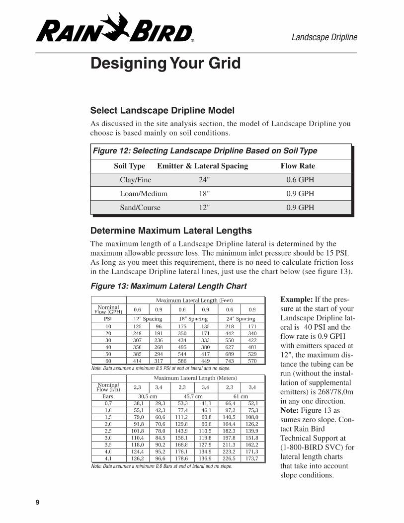
Select Landscape Dripline ModelAs discussed in the site analysis section, the model of Landscape Dripline youchoose is based mainly on soil conditions.
Figure 13: Maximum Lateral Length Chart
Determine Maximum Lateral LengthsThe maximum length of a Landscape Dripline lateral is determined by themaximum allowable pressure loss. The minimum inlet pressure should be 15 PSI.As long as you meet this requirement, there is no need to calculate friction lossin the Landscape Dripline lateral lines, just use the chart below (see figure 13).
Example: If the pres-sure at the start of yourLandscape Dripline lat-eral is 40 PSI and theflow rate is 0.9 GPHwith emitters spaced at12", the maximum dis-tance the tubing can berun (without the instal-lation of supplementalemitters) is 268'/78,0min any one direction.Note: Figure 13 as-sumes zero slope. Con-tact Rain BirdTechnical Support at(1-800-BIRD SVC) forlateral length chartsthat take into accountslope conditions.
Figure 12: Selecting Landscape Dripline Based on Soil Type
Soil Type Emitter & Lateral Spacing Flow Rate
Clay/Fine 24" 0.6 GPH
Loam/Medium 18" 0.9 GPH
Sand/Course 12" 0.9 GPH
9
Note: Data assumes a 0,6 Bars at end of and slope.
Note: Data assumes a 8.5 PSI end of and
Maximum Lateral Length (Meters)l) 2,3 3,4 2,3 3,4 2,3 3,4
Bars 30,5 45,7 cm 61 cm0,7 29,3 53,3 41,1 66,4 52,11,0 55,1 42,3 77,4 46,1 97,2 75,31,5 79,0 60,6 111,2 60,8 140,5 108,02,0 91,8 70,6 129,8 96,6 164,4 126,22,5 101,8 78,0 143,9 110,5 182,3 139,93,0 110,4 84,5 156,1 119,8 197,8 151,83,5 118,0 90,2 166,8 127,9 211,3 162,24,0 124,4 95,2 176,1 134,9 223,2 171,3
173,7
Maximum Lateral (Feet)l
Fl PH) 0.6 0.9 0.6 0.9 0.6 0.9
PSI 12" Spacing 18" Spacin 4" acing
10 125 96 175 135 17120 249 191 350 171 442 34030 307 236 434 333 550 42240 350 268 495 380 627 48150 385 294 544 417 689 529
414 570

Design Guide
Designing Your Grid (continued)
Determine Lateral Line SpacingUse the following steps to calculate Landscape Dripline lateral spacing.
Figure 15: Equal Lateral Line Spacing
Figure 14: Lateral Line Spacing Calculations
EndFeed
* The edge offset is 2" from hardscape and 4" from non-hardscape.
10
Follow the example below to determine the space between lateral lines:
To Get This: Do This: Calculations Totals
1. Width of the planted area Measure the width in feet 5 feet
2. Width of planted area in inches: Multiply feet by 12 to get inches 5' x 12" = 60 inches
3. Actual width of the grid: Subtract edge offset (multiply 2 x 2 = 4)* 60" - 4" = 56 inches
4. No. of spaces between laterals: Divide grid width by emitter spacing (12", 18", 24") 56" ÷ 12" = 4.6 spaces
5. Actual no. of spaces: Round up to the next whole number 4.6 = 5 spaces
6. Actual space between lateral lines: Divide grid width by number of spaces in grid 56"÷5 spaces = 11.2"
7. No. of lateral line rows in the grid: Add one to no. of spaces 5 + 1 = 6 rows
Use the worksheet below to determine the space between lateral lines for your system:
To Get This: Do This: Calculations Totals
1. Width of the planted area Measure the width in feet
2. Width of planted area in inches: Multiply feet by 12 to get inches
3. Actual width of the grid: Subtract edge offset (multiply 2 x 2 = 4)*
4. No. of spaces between laterals: Divide grid width by emitter spacing (12", 18", 24")
5. Actual no. of spaces: Round up to the next whole number
6. Actual space between lateral lines: Divide grid width by number of spaces in grid
7. No. of lateral line rows in the grid: Add one to no. of spaces
Equal
Width of planted area
�
�
Equal
Equal
Equal
Equal
�
�
�
�
�
�
�
�
�
�
�
�
�
�
Offset from
edge: 2” from hardscape, 4” from
planting beds

Landscape Dripline
Designing Your Grid (continued)
Supplemental WateringOccasionally, plants within the Landscape Dripline watering grid will requiresupplemental irrigation. When Xeri-Bug emitters are inserted into the grid, the ad-ditional flow must be taken into consideration. For example, if 5 GPH of the flow isadded to the grid through the addition of Xeri-Bug emitters, the length of the later-als must be reduced by 5 GPH plus a safety factor of 20 percent (1 GPH in this ex-ample) which brings the total flow adjustment to 6 GPH. See the following example:
1. Divide the adjusted flow by the flow rate of the Landscape Dripline emitterto determine how many inline emitters it takes to equal this adjusted flow:
6 GPH (adjusted flow) ÷ 0.9 GPH (emitter flow rate) = 6.7 or 7 emitters
2. Multiply the number of emitters by the spacing of the Landscape Driplinebeing used:
7 emitters x 12" emitter spacing = 84" length of tubing
3. To convert inches into feet:
84" ÷ 12" = 7'
4. Adjust the possible maximum lateral length by 7'. From figure 12, at 45 PSI,the maximum lateral length for 0.9 GPH and 12" emitter spacing is 236'. Toget the adjusted maximum length of tubing:
236' - 7' = 229'
Figure 16: Supplemental Watering Layout (see note at top of page)
11
Note: If yourgrid designdoes not needto considersupplementalwatering, godirectly topage 12,"CalculatingFlow." Usethis section ifyou are usingLandscapeDripline in amixed plantingscheme.
Dense ground cover planting (shown in gray) irrigated with Landscape Dripline.
�Manual flush valve
�
Rain Bird Control ZoneKit XCZ-075 (3/4”)
Sparse shrub planting (shown in white) irrigated with supplemental single-outletemitters connected to Rain Bird Landscape Dripline tubing. Emitters use Rain Bird1/4” distribution tubing, TS-025 stakes and DBC-025 bug caps.

Design Guide
Designing Your Grid (continued)
12
Figure 17: Landscape Dripline Lateral Flow Per 100' (GPM)
Guidelines For Zoning a Landscape Dripline GridOnce you know the total flow of your grid (30 GPM in this example), determine the number ofzones and their respective sizes using the information in the chart below.
* Based on maximum velocity of 5' per second. ** Per 100' of tubing.
Follow the example below to determine the flow rate:
To Get This: Do This: Calculations Totals
1. Length of tubing in feet: Determine the total length in feet from grid 2,000 feet
2. Length of tubing in inches: Multiply feet by 12 to get inches 2,000' x 12" = 24,000 inches
3. No. of emitters in the zone: Divide length by emitter spacing (12", 18", 24") 24,000" ÷12" = 2,000 emitters
4. Total no. of emitters: Round up to next whole number 2,000 = 2,000 emitters
5. Flow rate in GPH: Multiply no. of emitters by flow rate (0.6 or 0.9 GPH) 2,000 x 0.9 = 1,800 GPH
6. Flow rate in GPM: Divide GPH by 60 to get gallons per minute 1,800 ÷ 60 = 30 GPM
Use the worksheet below to determine the flow rate for your system:
To Get This: Do This: Calculations Totals1. Length of tubing in feet: Determine the total length in feet from grid
2. Length of tubing in inches: Multiply feet by 12 to get inches
3. No. of emitters in the zone: Divide length by emitter spacing (12", 18", 24")
4. Total no. of emitters: Round up to next whole number
5. Flow rate in GPH: Multiply no. of emitters by flow rate (0.6 or 0.9 GPH)
6. Flow rate in GPM: Divide GPH by 60 to get gallons per minute
Figure 19: Determining Maximum Flow Per Zone
Sch. 40 PVC Max. Flow* PSI Loss** Poly pipe Max. Flow* PSI Loss**Header Size GPM Header Size GPM
1/2" 4.7 GPM 7.7 PSI 1/2" 4.7 GPM 8.8 PSI
3/4" 8.3 GPM 5.6 PSI 3/4" 8.3 GPM 6.3 PSI
1" 13.5 GPM 4.2 PSI 1" 13.5 GPM 4.8 PSI
1-1/2" 33.9 GPM 2.9 PSI 1-1/2" 31.8 GPM 2.9 PSI
2" 52.4 GPM 1.9 PSI 2" 52.4 GPM 2.2 PSI
Calculating FlowUse the following chart, or the steps below to calculate the flow rate of this LandscapeDripline zone. For this example we will assume coarse soil and Landscape Driplinemodel: LD-09-12-500.
Figure 18: Flow Rate Calculations
.6 GPH
Emitter Flow
.9 GPH
GPM/100'
1.0 GPM
1.5 GPM
.67 GPM
1.0 GPM
.50 GPM
12" Spacing 18" Spacing 24" Spacing
.75 GPM

Landscape Dripline
Designing Your Grid (continued)
13
Calculating Precipitation RatesUse the following steps to calculate the precipitation rate and station runtime. Precipitation rate is the rate at which Landscape Dripline applies wa-ter to the soil. ET is water loss from the soil and plants.
1. Determine ET (evapotranspiration)To determine ET, call your local agricultural extension or farm advisor or usethe Daily ET Rates chart (see figure 20) to determine ET in your area. For ourexample, we will use 0.2" per day, which is the ET for Los Angeles.
2. Calculate PR (Precipitation Rate)
231.1 (a fixed number in formula) x 0.9 GPH (emitter flow rate) =12" (emitter spacing) x 11.2" (row spacing from figure 13, page 10)
3. Calculate Station Run Time
Daily ET: 0.2" per day = 0.13 hours x 60 minutes = 7.8 or 9 minutesPrecipitation rate: 1.5" per hour
Atlanta, GA .24Boston, MA .20Buffalo, NY .20Bismark, ND .20Denver, CO .18Detroit, MI .20Honolulu, HI .20Houston, TX .27Kansas City, MO .21Las Vegas, NV .30Los Angeles, CA .20Louisville, KY .20Palm Springs, CA .37Pensacola, FL .26Portland, OR .18Phoenix, AZ .30Seattle, WA .15
Inches Per Day
Figure 20: DailyET Rates
1.5"per hr.(rounded)
12
18
24
12
18
24
0.96
0.69
0.28
1.44
0.6 0.9
1.03
0.41
Emitter Spacing Lateral Spacing
Emitter Flow Rate
Figure 21: Landscape Dripline Grid Precipitation Rates (in/hr)

Design Guide
Designing Your Grid (continued)
Figure 24: Spacing of Stakes or Staples
Soil Type Stake Spacing Additional Stakes
Clay/Fine 4'-6' (1.2-1.8 m) Before & after every turn
Loam/Medium 3'-5' (0.9-1.5 m) Before & after every turn
Sand/Course 2'-3' (0.6-0.9 m) Before & after every turn
Figure 22: Two outlet ports function as back up air relief valves.
14
Pressure CompensationBecause of Rain Bird's ADI technology, Landscape Dripline pressure compen-sates without reducing the size of the emitter flow path. This feature is the pri-mary reason Landscape Dripline delivers unsurpassed clog resistance. Since itis pressure compensating, the first emitter on the line will apply the sameamount of water as the last emitter on the line. Another advantage to LandscapeDripline is that it flushes without the use of a low-pressure flow spike that un-duly complicates the design process.
Stakes and StaplesLandscape Dripline requires the use of stakes or staples to install it securely tothe ground. Use the following table as a guide for staking:

Landscape Dripline
Landscape Dripline System Components
Rain Bird Compression Fittings, Universal Fittings, LOC Fittings and Barb Fittings.
Rain Bird 1800-RETRO provides 200-meshfiltration and 30-psi pressure regulation as apoint-of-connection for LD tubing.
Rain Bird LD-Series Landscape Dripline.
Rain Bird AF Series Automatic Filter Kits(1", 1-1/2" and 2" models shown).
Rain Bird Control Zone Kits.
15

LandscapeDripline
The Next Generationof Inline Tubing
Design andInstallation
Guide
For Technical Assistance,Call Toll Free1-800-247-3782
Rain Bird Corporation970 West Sierra Madre Avenue, Azusa, CA 91702Phone: (626) 963-9311 Fax: (626) 812-3411Specification Hotline: 1-800-458-3005 (U.S. only)Rain Bird Technical Services (800) 247-3782 (U.S. only)
Rain Bird International, Inc.145 North Grand Avenue, Glendora, CA 91741Phone: (626) 963-9311 Fax: (626) 963-4287www.rainbird.comRain Bird BBS: (520) 741-6153
Recycled Paper.
Rain Bird. Conserving More Than Water
® Registered Trademark of Rain Bird Sprinkler Mfg. Corp.©1999 Rain Bird Sprinkler Mfg. Corp. 1/00
D39212B