landform degradation and slope processes - brown … · journal of geophysical research, vol. 106,...
TRANSCRIPT

JOURNAL OF GEOPHYSICAL RESEARCH, VOL. 106, NO. El2, PAGES 33,223-33,240, DECEMBER 25, 2001
Landform degradation and slope processes on Io' The Galileo view
ß
Jeffrey M. Moore, • Robert J. Sullivan,- Frank C. Chuang, • James W. Head III, 4 Alfred S. McEwen s Moses P Milazzo, s Brian E Nixon, 4 Robert T Pappalardo, 4'6 Paul M. Schenk, 7 and Elizabeth P. Turtle s
Abstract. The Galileo mission has revealed remarkable evidence of mass movement and
landform degradation on Io. We recognize four major slope types observed on a number of intermediate resolution t-250 m pixel -t) images and several additional textures on very high resolution (-10 m pixel- ) images. Slopes and scarps on Io often show evidence of erosion, seen in the simplest form as alcove-carving slumps and slides at all scales. Many of the mass movement deposits on Io are probably mostly the consequence of block release and brittle slope failure. Sputtering plays no significant role. Sapping as envisioned by McCauley et al. [1979] remains viable. We speculate that alcove-lined canyons seen in one observation and lobed deposits seen along the bases of scarps in several locations may reflect the plastic de- formation and "glacial" flow of interstitial volatiles (e.g., SO2) heated by locally high geo- thermal energy to mobilize the volatile. The appearance of some slopes and near-slope sur- face textures seen in very high resolution images is consistent with erosion from sublimation- degradation. However, a suitable volatile (e.g., H2S) that can sublimate fast enough to alter Io's youthful surface has not been identified. Disaggregation from chemical decomposition of solid S20 and other polysulfur oxides may conceivably operate on Io. This mechanism could degrade landforms in a manner that resembles degradation from sublimation, and at a rate that can compete with resurfacing.
1. Introduction
Mass movement and landtbrm degradation reduces topog- raphic relief by moving surface materials to a lower gravita- tional potential. Landform degradation commonly involves a reduction in material strength (e.g., loss or weakening of an interparticle binding agent or decrease in mechanical strength allowing disintegration or plastic deformation) and transport of this material under the influence of gravity. The identifi- cation of specific landform types associated with mass movement and landform degradation permits inferences about local sediment particle size and abundance, the nature of the binding cement, and transportation processes. Generally, mass movements on Earth can be classified in terms of the
particle sizes and the speed of the material moved during transport [Sharpe, 1939; k'arnes, 1958, 1978; Coates, 1977].
• NASA Ames Research Center, Mofl•tt Field, California. 2 Center for Radiophysics and Space Research, Cornell University,
Ithaca, New York. '• Department of Geological Sciences, Arizona State University,
Tempe, Arizona. 4 Department of Geological Sciences, Brown University, Providence,
Rhode Island.
s Lunar and Planetary Laboratory, University of Arizona, Tucson, Ari- zona.
6 Now at Astrophysical and Planetary Sciences Department, University of Colorado, Boulder, Colorado.
7Lunar and Planetary Institute, Houston, Texas.
Copyright 2001 by the American Geophysical Union.
Paper number 2000JE001375. 0148-0227/01/2000J E001375509.00
Such classification schemes have been used to characterize
mass movements on Mercury, Venus, the Moon, Mars, and the Galilean satellites [e.g., Sharp, 1973; Ma/in and Dzurisin, 1977; Malin, 1992; Schenk and Bulmer, 1998; Moore et al., 1999; Chuang and Greeley, 2000]. The character of extrater- restrial movements can only be inferred fi'om the resulting de- posits' morphologies since resolution is nearly always insuffi- cient to observe individual particles within the deposits.
With few exceptions, details of slope modification on Io generally are not obvious in Voyager images. Voyager l im- ages of Io revealed steep slopes on the flanks of isolated mountains, along interior walls of calderas, and as scarps within plains units. McCauley et al. [1979] and Schaber [1982] reported observations of arcuate or digitate scarps, es- pecially those in the south polar region, that suggested that some slopes on Io were subject to recession by mass wasting. Schaber [1982] reported lobate scarps along the flanks of some mountains which he noted resembled large landslides. Schenk and Bulmer [1998] recognized and discussed in detail a large debris apron along the southernmost flank of Euboea Montes, evaluated, in part, fi'om a stereo-derived topography model. Schaber [1982] observed the absence of slumps in caldera walls and proposed that this was strong evidence tbr substantial wall strength.
In most cases, Galileo images acquired at <200 m pixel '• resolution and high incidence angle and/or in stereo were re- quired to reveal landtbrms on icy Galilean satellites charac- teristic of mass movement [e.g., Moore et al., 1999; Chuang and Greeley, 2000]. This is also true fbr Io. Here we report observations made during the first three close Galileo fiybys (I24, I25, and I27) of that satellite, which took place in late 1999 and early 2000. In this study we identity and describe
33,223

33,224 MOORE ET AL.' MASS WASTING ON IO
;..:?
/...// .
ß 2'5 km ß
Figure 1. A mosaic of the Tvashtar caldera complex (centered at •-60øN, 120øW) shows four volcanic vents in this area, one of which was erupting during the I25 flyby, creating the pixel bleed seen on the image. Three of the four vents are distributed across the floor of the depression that, in turn, is partly enclosed within a plateau rising,•l km above the surrounding plains. Along scarps of this plateau several different slope types are seen. Boxes indicate the locations of subsequent figures used to illustrate individual slope types (numbered by figure). The letter "A" marks the location of alcove-rimmed canyons discussed in the text. (Mosaic is composed of images 25I•040 and 2510041 with nominal resolutions of 183 m pixel '• superposed on a portion of a 1.3 km pixel -•, global mosaic ac- quired during orbit C21. The view is oblique. Illumination is fi'om the left. North is up.)
slope morphologies seen in the new images of Io that are in- dicative of slope degradation and mass wasting and develop working hypotheses tbr the processes and materials involved in the evolution of these landforms.
2. Observations and interpretations The I24, I25, and I27 Io observations show several distinct
degradation styles of slopes associated with mountain sides, caldera walls, and plateau margins, but degradational style does not always correlate directly with tectonic or vol- canological setting. We begin with the rich variety of slope morphologies in the area of Tvashtar Catena (•63øN, 123øW) seen in observations 25ISGIANTS01 and 27ISTVASHT01
(which also provide stereo information), then turn to other Galileo observations elsewhere on Io where similar slope morphologies are f•)und. Finally, we discuss two very high
"resolution observations that, while very selective in coverage, offer additional insights into slope degradation on Io.
The I25 mosaic of the Tvashtar caldera complex (Figure 1) shows four recently active volcanic vents in this area, one of
which was erupting during the I25 flyby [McEwen et al., 2000]. Three of the four vents are distributed across the floor of a 70 x 170 km depression that, in turn, is partly enclosed within a plateau rising about a kilometer above the surround- ing plains [McEwen eta!., 2000; Dtrtle eta!., this issue], Four distinct slope morphologic types are tbund along the caldera walls and the extensive inward and outward t•tcing walls of the plateau margins. These morphologies, described in detail below, reflect four different styles or states of slope degradation and may also reflect variations in material strength and/or susceptibility to modification processes. These morphologies also are seen elsewhere on the planet in other Galileo observations.
2.1. Type U Slopes
The southeastern vent of the Tvashtar complex is a kidney- shaped pit with a tlat floor spanning about 30 x 60 km (Figure 2). The steep walls lining this pit generally lack deep alcoves or alternating spurs and gullies. Consistent with interpreta- tions of similar pits by many previous workers, this pit proba-
MOORE ET AL.' MASS WASTING ON IO 33,225
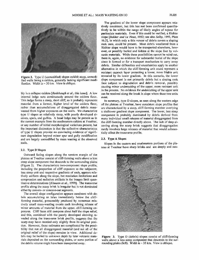
Figure 2. Type U (unmodified) slopes exhibit steep, unmodi- fled walls lining a caldera, generally lacking significant modi- fication. Width is --- 30 km. View is oblique.
bly is a collapse caldera [Radebaugh eta!., this issue]. A low internal ledge runs continuously around the caldera floor. This ledge forms a steep, short clift; so it probably represents material fi'om a tbrmer, higher level of the caldera floor, rather than accumulations of disaggregated debris mass- wasted t¾om higher exposures on the walls. We characterize type U slopes as relatively steep, with poorly developed al- coves, spurs, and gullies. A basal ledge may be present as in the current example from the southeastern caldera at Tvashtar, or any number of initial morphological variations present, but the important distinction is that the collective characteristics of type U slopes provide no convincing evidence of signifi- cant degradation beyond minor spur and gully modification and are largely unmodified by mass wasting at the observed scale.
2.2. Type D Slopes
Outward facing slopes along the western margin of the plateau at Tvashtar consist of cliff-lbrming walls above a less steep slope component that descends to the surrounding plains (Figure 3). The characteristic two-component slope profile, including the proportion of cliff exposure to the subjacent, less steep unit and respective gradients of each, appears rela- tively uniform along the slope, but resolution limitations and compression and radiation artifacts in the images limit quan- titative determinations [K!aasen eta!., 1999]. The transverse profile along the scarp brink is irregular but is not dominated either by convex- or concave-out segments.
The overall slope configuration appears consistent with de- bris accumulating as talus immediately below the cliff- tbrming material, presumably produced by numerous rela- tively small mass-wasting events each involving release of minor amounts of material t¾om the upper, cliff-forming ex- posures. Cliff t•.ces still compose about half the slope reliet; and this, combined with the poorly developed alcoving re- vealed along the transverse brink profile, suggests that the scarp may have receded only slightly from its original posi- tion. However, these estimates are complicated by the possi- bility that not all disaggregated material (and not all of the original relief of the slope) remains in view. Additional de- bris may be buried to unknown depth by later volcanic mate- rials deposited on the surrounding plains, or some portion of the debris volume might have been transported away.
The gradient of the lower slope component appears rela- tively consistent, but this has not been confirmed quantita- tively to be within the range of likely angles of repose particulate materials. Even if this could be verified, a Richter slope [Bakker and Le tteux, 1952; see also Selby, 1993, Plate 16.2], in which only a thin veneer of debris covers a sloping rock core, could be present. Most debris weathered from a Richter slope would have to be transported elsewhere, how- ever, or possibly buried and hidden at the slope foot by vol- canic materials. While these possibilities cannot be ruled out, there is, again, no evidence tbr substantial burial of the slope since it tbrmed or tBr a transport mechanism to carry away debris. Similar difficulties and uncertainties apply to another alternative in which the cliff-tbrming unit could represent a resistant caprock layer protecting a lower, more friable unit revealed by its lower gradient. In this scenario, the lower slope component is not primarily debris but a sloping rock t•.ce subject to degradation and debris removal, possibly causing minor undercutting of the upper, more resistant unit in the process. No evidence tbr undercutting of the upper unit can be resolved along the break in slope where these two units meet.
In summary, type D slopes, as seen along the western edge of the plateau at Tvashtar, have consistent slope profiles that are characterized by a steep, cliftZtbrming member overlying a shallower gradient slope component. The lower, less steep component is probably dominated by debris derived fi'om many individual small releases of material disaggregated from the cliff-lbrming member directly above. The lack of deep al- coving along the scarp brink suggests that disaggregation rarely involves large releases of material that would substan- tially affect the transverse profile.
2.3. Type A Slopes
Slopes in the eastern and southeastern portions of the pla- teau at Tvashtar have sharp brinks and are deeply and con-
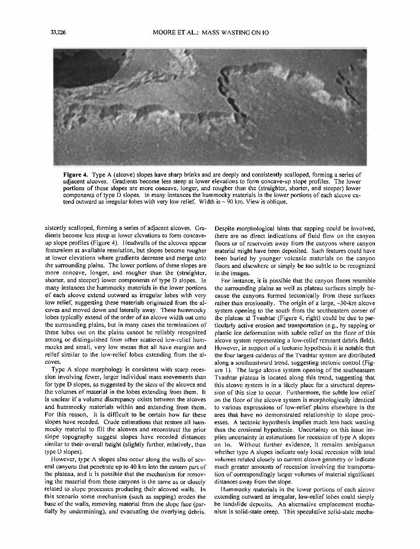
Figure 3. Type D (debris) slopes consist of cliff-forming walls above a less-steep component that descends to the sin- rounding plains (left). Width is --- 35 km. View is oblique.
33,226 MOORE ET AL ß MASS WASTING ON IO
Figure 4. Type A (alcove) slopes have sharp brinks and are deeply and consistently scalloped, tbrming a series of adjacent alcoves. Gradients become less steep at lower elevations to tbrm concave-up slope profiles. The lower portions of these slopes are more concave, longer, and rougher than the (straighter, shorter, and steeper) lower components of type D slopes. In many instances the hummocky materials in the lower portions of each alcove ex- tend outward as irregular lobes with very low telleft Width is- 90 kin. View is oblique.
sistently scalloped, tbrming a series of adjacent alcoves. Gra- dients become less steep at lower elevations to tbrm concave- up slope profiles (Figure 4). Headwalls of the alcoves appear featureless at available resolution, but slopes become roughel' at lower elevations where gradients decrease and merge onto the surrounding plains. The lower portions of these slopes are more concave, longer, and rougher than the (straighter, shorter, and steeper) lower components of type D slopes. In many instances the hummocky materials in the lower portions of each alcove extend outward as irregular lobes with very low reliet} suggesting these materials originated fi'om the al- coves and moved down and laterally away. These hummocky lobes typically extend of the order of an alcove width out onto the surrounding plains, but in many cases the terminations of these lobes out on the plains cannot be reliably recognized among or distinguished fi'om other scattered low-relief hum- mocks and small, very low mesas that all have margins and relief similar to the low-relief lobes extending from the al- coves.
Type A slope morphology is consistent with scarp reces- sion involving ti•wer, larger individual mass !novements than tbr type D slopes, as suggested by the sizes of the alcoves and the volumes of material in the lobes extending fi'om them. It is unclear if a volume discrepancy exists between the alcoves and hummocky materials within and extending I¾om them. For this reason, it is difficult to be certain how tb.r these slopes have receded. Crude estimations that restore all hum- mocky material to till the alcoves and reconstruct the prior slope topography suggest slopes have receded distances similar to their overall height (slightly thrthcr, relatively, than type D slopes).
However, type A slopes also occur along the walls of sev- eral canyons that penetrate up to 40 km into the eastern part of the plateau, and it is possible that the mechanism tbr remov- ing the material fi'om these canyons is the same as or closely related to slope processes producing their alcoved walls. In this scenario some mechanism (such as sapping) erodes the base of the walls, removing material t?om the slope face (par- tially by undermining), and evacuating the overlying debris.
Despite morphological hints that sapping could be involved, there are no direct indications of fluid flow on the canyon floors or of reservoirs away t¾om the canyons where canyon material might have been deposited. Such ligatures could have been buried by youngel' volcanic materials on the canyon floors and elsewhere or simply be too subtle to be recognized in the images.
For instance, it is possible that the canyon floors resemble the surrounding plains as well as plateau surthces simply be- cause the canyons tbrmed tectonically fi'om these surthces rather than erosionally. The origin of a large, -30-km alcove system opening to the south ti-om the southeastern corner of the plateau at Tvashtar (Figure 4, right) could be due to par- ticularly active erosion and transportation (e.g., by sapping or plastic ice detbrmation with subtle relief on the floor of this alcove System representing a low-relief remnant debris field). However, in support of a tectonic hypothesis it is notable that the tbur largest calderas of the Tvashtar system are distributed along a southeastward trend, suggesting tectonic control (Fig- ure 1). The large alcove system opening of the southeastern Tvashtar plateau is located along this trend, suggesting that this alcove system is in a likely place tbra structural depres- sion of this size to occur. Furthermore, the subtle low relief on the tloor o1' the alcove system is morphologically identical to various expressions of low-relief plains elsewhere in the area that have no demonstrated relationship to slope proc- esses. A tectonic hypothesis implies much less back wasting than the erosional hypothesis. Uncertainty on this issue im- plies uncertainty in estimations tbr recession of type A slopes on Io. Without further evidence, it remains ambiguous whether type A slopes indicate only local recession with total volumes related closely to current alcove geometry or indicate much greater amounts of recession involving the transporta- tion of correspondingly larger volumes of material significant distances away ti'om the slope.
Hummocky materials in the lower portions of each alcove extending outward as irregular, low-relief lobes could simply be landslide deposits. An alternative emplacement mecha- nism is solid-state creep. This speculative solid-state mecha-

MOORE ET AL.: MASS WASTING ON IO 33,227
'Figure 5. Type T (terraced) slopes are characterized by subparallel terracing at higher elevations and (in most cases) hummocky material ending at distinct, sometimes convex-up, lobate margins at lower elevations. (a) Prominent terracing along the scarp t•ce. (b) Less t•ce terracing but small prominent parallel scarps behind the main scarp. Figure 5a is --- 55 km wide, and Figure 5b is --35 km wide. The view is oblique.
nism might involve contributions from a ballistically em- placed volatile component in pyroclastic deposits, which, al- ter accumulating on slopes to a threshold thickness, could en- able movement of the entire deposit, including debris shed fi'om the slope itself; downslope under its own weight, analo- gous in some ways to water-ice-cored active rock glaciers on Earth. This process will be considered in more detail in sec- tion 3.4.
2.4. Type T Slopes
Type T slopes are characterized by subparallel terracing at higher elevations and (in most cases) hummocky material ending at distinct, sometimes convex-up, lobate margins at lower elevations but there are wide variations within this
category. Type T slopes at Tvashtar are most prominent along the southern-to-western inward facing walls of the pla- teau, and along the southwestern outward-lhcing walls (Figure 5a). Less prominent examples are found along eastern inward t•cing plateau walls (Figure 5b). The relative size of the lower hummocky component varies considerably with loca- tion and seems correlated with the degree of terracing. The hummocky unit extends up to 20 km fi'om the western inward t•cing walls where terracing is most developed, extends <10 km fi'om the southern inward thcing walls and is not t•)und at all along the foot of the eastern inward thcing wall. In the latter case, where terracing is also much less prominent, the lower hummocky unit may have been much smaller or lower to begin with, then was buried by volcanic materials from the adjacent calderas. Burial might also truncate the exposures of other hummocky deposits elsewhere around the walls rim- ming the large 70 x 170 km depression. Along the southwest- ern outward thcing walls, the hummocky component with convex-up margins is so prominent that it composes more of the total slope relief than the subparallel terracing t•rther up- slope.
Type T slope morphology is consistent with brittle fhilure, coherent slumping, and in some instances partial rotation of
slope walls, producing terraces and minor scarps near the head of the failure surt•ce. Slope material is transported down and laterally away to form hummocky deposits with margins that are resolved as convex-up in the largest cases. Subparallel terracing on type T slopes is the most consistent morphological distinction fi'om type A slopes (which are marked by alcoves at their higher elevations) and indicates a different mass-wasting style. Multiple terracing of type T slopes suggests that slope recession in these locations is a progressive process involving many separate large t•ilures.
In contrast, there are no indications of even minor terracing behind the alcoves of type A scarps, suggesting that alcove- creating slope t•ilures there are singular events or at least much smaller and/or rarer. This could mean that destabilizing ellEcts such as removal of toe material or raising of relief (e.g., by lowering the base level) occur more frequently along type T slopes. If so, this would be consistent with most type T slopes at Tvashtar occurring along inward thcing plateau margins, where the base level might be subject to fluctuations fi'om activity in the magma chamber system beneath the cal- deras. The series of t•ilures creating the type T slope along the southwestern outward thcing margin is harder to under- stand. The hummocky run-out deposit here is especially prominent, and subparallel terracing occurs as much as 50 km back fi'om the slope margin. Portions of the plateau appear to have broken up in response to lateral tensional stresses, with uplitl of the plateau margin as a possible stress source.
2.5. Slope Exposures at Other Localities
Many slopes on Io have morphologies similar to the four slope types described above in the Tvashtar area. Type A slopes, variations of type T slopes, and perhaps type U slopes are found along plateau margins and mountain sides seen in the Zal Montes and its surroundings (25ISTERM01 and 27ISZALTRM01 Galileo observations). The Zal Montes (Figure 6) consist of a 60 x 150 km plateau and a higher-relief complex ridge trending SSE tbr 200 km 'Turtle et al., this is-

33,228 MOORE ET AL.: MASS WASTING ON IO
Figure 6. A plateau in the Zal Montes located at •42øN, 77øW exhibiting two types of slopes (images 2510060 and 2510061, 260 m pixel-•). Type A slopes are tbund near "A," and type T slopes are located near "T." The view is oblique. Illumination is fi'om the letl. North is toward tl•e top letl.
sue]. A 120-km-diameter caldera lies between these con- structs. The area is seen closer to the terminator in the 260 m
pixel '• 125 observation, which also includes an isolated un- named mountain to the southwest, but the 335 m pixel -• I27 observation (Figure 7) has more complete coverage of the higher-relief SSE trending mountain ridge. Type A slopes are prominently displayed along the northern margin of the pla- teau; the viewing geometry shows characteristic lobate de- posits extending up to 30 km fi'om individual alcoves (Figure 6). Subtle albedo patterns on the plains beyond the lobate de- posits could mark where fluid-like material has flowed fi'om the type A slopes. However, these patterns also are very similar to those commonly tbund elsewhere on plains t•r t?om slopes and so may simply be lava flows. Shallow troughs and swales on the southeastern part of the plateau transform near the southern margin into terraces of type T slopes. Hum- mocky lobes (thicker and more extensive than those associ-
ated with type A slope alcoves on the other side of the pla- teau) extend 40 km to the south from these terraced scarps.
Subtle near-horizontal lineations mark west thcing slopes of the northern end of the higher-relief mountain ridge in the Zal Montes (Figure 7). These could represent remnants of layered plains material uplitled with the main mountain mass [Schenk and Bulmer, 1998; Turtle et aL, this issue]. Alternatively, these t•atures could mark the locations of slump terraces typi- cal of type T slope degradation. For this scenario we specu- late that the massif progressively shed relatively weaker near- surt•ce materials aside during uplift as it emerged at the sur- thee; the original surthce materials progressively shoved aside by the steep, emerging massif peak are the terraced, lower gradient materials composing the lower portion of the moun- tainside. Extended hummocky run-out deposits are absent t?om the plains at the tbot of this slope, but there are two pos- sible explanations: (1) slumping materials simply may not

MOORE ET AL.: MASS WASTING ON IO 33,229
Figure 7. A ridge in the Zal Montes located at-35øN, 73øW. Note the subtle near-horizontal lineations mark west facing slopes of the northern end of the higher-relief mountain ridge, which could mark the locations of slump terraces typical of type T slope degradation (images 2710059 and 2710060, 335 m pixel-I). The view is oblique. Illumination is fi'om the bottom lett. North is toward the top leit.
have been shoved laterally very tkr as the massif emerged at the surIkce and/or (2) longer run-out landslide deposits may have been generated either during massif upliI• or later degra- dation of the slope but they may have been covered or eroded away by subsequent volcanic eruptions (e.g., by lava flowing north along the tbot of the slope from a small adjacent cal- dera).
Two mountain complexes associated with Gish Bar Patera are captured in the eastern half of the 480-570 m pixel -• 24ISAMSKGI01 observation (Figure 8). Variations of type T slope degradation are found on all of these features. A pla- teau extends westward from the larger mountain complex near Gish Bar Patera. This plateau has a lobate, digitate western margin that may be a landslide deposit. As discussed previ- ously tbr the smaller isolated mountain to the northeast, an alternative hypothesis tbr this type of morphology involves massif uplit• disturbing a much weaker overlying surface layer where the massif emerges from the surt•tce. The alter- native explanation was also explored by Schenk and Bulmer [1998] for a t•ature associated with the Euboea Montes. Continued uplitl results in the weaker surthce materials being partly raised and partly compressed laterally as they are gradually shed aside. This process produces relatively high- relief mountain slopes with two elements: a steeper, upper component con'esponding to the massif itself (probably with a minimum of adhered debris fi'om originally overlying surt•ce
materials); and a lower, less steep component consisting of a series of partly compressed, tilted, and potentially unstable slumps of what were originally surface deposits, covering the lower flanks of the uplifted massif and extending outward onto the surrounding plains. Few details are exposed on the slab-like, almost tkmtureless upper flanks of this mountain complex, similar to the upper flanks of the smaller isolated mountain to the northeast. Skythia Mons is a more extended, lower-relief structure than the mountains around Gish Bar
Patera. The flanks of Skythia Mons display alternating grooves and ridges oriented only approximately perpendicular to local gradient (Figure 9). Minor examples of these stria- tions along the eastern lower flanks might owe part of their character to expressions of internal layering, but elsewhere, especially along the southeast margin, this texture does not convincingly suggest exposures of horizontal strata. Instead, the striations along the southeast margin define arcuate (con- cave outward) patterns that are expressed at lower elevations as a series of shallow alcoved terraces with arcuate scarps. Perhaps structural disturbances are largely responsible tbr the striated relief around the margin of this prominent plateau, and along the southeast margin these disturbances have caused back wasting of the plateau by slumping of the flanks.
The margins of Shamshu Mons (Figure 10), imaged at 342 m pixel -• during I27, show evidence of type A slope degrada- tion but with morphological variations perhaps linked to ob-

33,230 MOORE ET AL.' MASS WASTING ON IO
Figure 8. The mountain complex near Gish Bar Patera (im- ages 2410111 and 2410117,-•500 m pixel'•). The plateau at left has a lobate, digitate western margin interpreted as a land- slide deposit. The view is oblique. Illumination is fi'om the lefL North is roughly up.
scuration by lava flows. Unlike type A slopes in many other places, alcoves along the northwest tkcing 11ank of Shamshu Mons have flat floors with no traces of low-relief lobes ex-
tending fi'om them. Lava apparently has flowed northeast fi'om a small caldera into the trough between the alcoves and an outlying, parallel ridge, burying the lower portions of the alcoves and tbl'ming their flat floors.
Very high resolution images with resolutions <10 m pixel '• were also obtained by Galileo, but these images cover an ex- tremely small portion of the satellite so their content is almost certainly not truly representative of the entire surtkce or proc- esses that occur there. Nevertheless, these images begin to show more of the actual geological complexity of the surtkce than more widespread, lower-resolution images can. Chaac caldera scarp (Figure 11) is captured in two images of the---9 m pixel '• 271SCHAAC_01 observation. Most of the scarp length captured in the images consists of a very steep cliff- tbrming member extending fi'om a sharp brink at the plateau edge right down to the caldera floor; shadow measurements indicate this cliff-tbrming member has a total relief of 2.8 km and descends at a gradient of around 70 ø [Radebattgh eta!., this issue]. The walls are dimly lit by scattered light in
shadow. The cliffs appear massive, with tbw hints of layering or of gullies or other features consistent with mass wasting. At lower resolution this would probably be identified as a type U (largely unmodified) slope. In some places, cliflk de- scend only about three fourths of the way to the caldera floor betbre changing abruptly to a component with a much lower gradient that descends the remainder of the total relief of the slope. The relatively consistent gradient of this lower compo- nent suggests that it could be debris accumulated from many small releases from cliff-tbrming material immediately above. However, several details suggest that an explanation as talus might be too simplistic. The interpretation of the lower- component material as talus would be more secure if there were corresponding cavities or gullies immediately above to suggest where this volume of material originated, but the scarp brinks appear as continuous in these locations as else- where along the walls where cliffs extend all the way down to the caldera floor. In one area the putative talus has an albedo pattern that cannot be explained easily as a shadows t¾om the clifik above but might be consistent with fingers of dark talus slumping down older, brighter exposures of the same unit in minor stability adjustments. It is not clear why at some point in the past portions of this putative talus would have been brighter, but complications associated with caldera activity could be involved. There are bright patches immediately ad- jacent on the caldera floor, and whatever brightened this por- tion of the caldera floor might also have brightened the puta- tive talus unit at one time; subsequent releases fi'om the cliff- tk)rming unit would be darker and would gradually cover bright deposits on the talus beginning at the higher elevations immediately below the clifik.
Figure 9. Striations along the southeast margin of Skythia Mons (•26øN, 97øW) define arcuate (concave outward) pat- terns that are expressed at lower elevations as a series of shallow alcoved terraces with arcuate scarps, which may be the result of back wasting of the plateau by slumping of the flanks (image 2410110, ---500 m pixel-•). The view is oblique. Illumination is fi'om the letL North is roughly up.

MOORE ET AL.' MASS WASTING ON IO 33,231
Figure 10. Margins of Shamshu Mons (-•12øS, 72øW), show evidence of type A slope degradation but with mor- phological variations caused by the lower portions of these slopes being obscured by lava flows (images 2710065 & 2710066, 342 m pixel'•). The view is oblique. Illumination is l¾om the upper letl. North is toward the upper right.
Ridge sets seen on some mountain flanks, such as Hi'iaka Montes (Figure 12), appear interleaved or en echelon. Ridges bitBrcate in some cases and have convex to convex-ramp ter- minations. Ridges in cross-trend profile appear rounded and may be the surface expression of folds. The morphology of individual ridges and the arrangement of ridge sets might best be interpreted as the manitOstation of compressional folds in a surt•ce layer overlying a shallow decollement, or perhaps a ductile subsurt•ce [Pappalardo and Greeley, 1995]. This ridge texture is most pronounced on slopes, which suggests that they t•)rmed by gravity sliding of a detached surt•ce layer. The orientation of ridges is always perpendicular to gradient where this texture is found. If Io's mountains tbrm by the tilting of preexisting crustal blocks, the shallower ridged facet may be the original (formerly flat) premountain surthce. Cumulative successions of plume fallout, SO2 con- densates, landslide material, and lava flows probably t•)rm stacks of thin, areally extensive layers within the plains. If such stacks of material have weak layer-to-layer contacts, they would be susceptible to del•)rmation and detachment when tilted. Schenk and Bulmer [1998] proposed a similar configuration as a contributor to mountain landslides on lo.
Figure 13 shows one image t?om an 1 l-image observation of a very small portion of Ot Mons obtained at very high resolution (9 m pixel -•) and low sun that we interpreted as a close-up view of ridge texture on mountain flanks such as is shown in Figure 12. Preencounter pointing predicted that
Figure 13 is located on the north flank of Ot Mons, but un- tbrtunately, the best available lower resolution context is a •-2 km pixel -• image acquired during the El4 encounter (Figure 14). In the high-resolution images the surface is covered by E-W trending ridges ---1-2 km long and 0.25-0.5 km wide. Just as with the ridges seen elsewhere at lower resolution (e.g., Figure 12), the Ot Mons ridges exhibit pinches and swells. Unlike the ridges in Figure 12, some of the Ot ridges appeared breached or disrupted. These breaches or disrup- tions take the lbrm of steep-walled amphitheaters. These am- phitheaters are often elongate and trend the same direction as the ridges. The floors of the amphitheaters are often covered with dark material that might have moved downslope to ac- cumulate there. Ten'acing within the walls of the amphithea- ters might be layering exposed by the amphitheater-k)rming process. If the Ot Mons flank ridges are indeed anticlinal ridges, such ridges commonly have extensional l•atures along their crests [Pappalardo and Greeley, 1995]. We speculate that the amphitheaters have t•)rmed initially as anticline cre- stal fi'actures and subsequently were widened into amphi- theaters by an erosional process that involves the disaggrega- tion of the outcrop.
During the 127 encounter, several 5.5 m pixel 'l images were acquired to look t•)r evidence of layering and to investigate Io's erosional processes. These images show complex pat- terns with pronounced variations in texture and albedo (Figure 15). Further complicating the interpretations is the fact that

33,232 MOORE ET AL ß MASS WASTING ON IO
Figure 11. A portion of the Chaac caldera scarp illustrating a type U slope (top two images are located at ---12øN, 1
158øW, images 2710009 and 2710010, ---9 m pixel- ). Most of the scarp length consists of a very steep clif•:•brming member (mostly in shadow) extending t?om a sharp brink at the plateau edge (at right) down to the caldera floor (at let•); shadow measurements indicate that this clit]:t•)rming member has a total relief of 2.8 km and descends at a gradient of around 70 ø. The walls are dimly lit by scattered light in shadow, but the clifi• appear massive, with only flew hints of layering, or of gullies or other fieatu!'es consistent with mass wasting. •Illumination is high and fi'om the right tbr the top two fi'ames. The lower image (image 2710036, ---180 m pixel' ) provides context. The bold boxes locate the top two fi'ames. Illumination is high and fi'om the let• tbr the context •?ame. North is roughly up.
MOORE ET AL' MASS WASTING ON IO 33,233
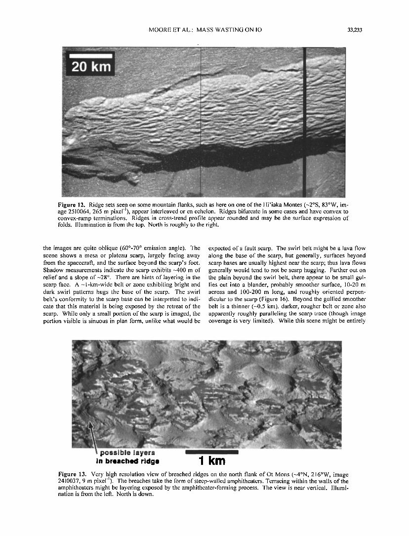
Figure 12. Ridge sets seen on some mountain flanks, such as here on one of the Hi'iaka Montes (---2øS, 83øW, im- age 2510064, 265 m pixel-I), appear interleaved or en echelon. Ridges bitercate in some cases and have convex to convex-ramp terminations. Ridges in cross-trend profile appear rounded and may be the surf•.ce expression of tblds. Illumination is fi'om the top. North is roughly to the right.
the images are quite oblique (60o-70 ø emission angle). The scene shows a mesa or plateau scarp, largely facing away from the spacecraft, and the surface beyond the scarp's foot. Shadow measurements indicate the scarp exhibits •400 m of relief and a slope of •28 ø. There are hints of layering in the scarp f•.ce. A •-l-km-wide belt or zone exhibiting bright and dark swirl patterns hugs the base of the scarp. The swirl belt's conformity to the scarp base can be interpreted to indi- cate that this material is being exposed by the retreat of the scarp. While only a small portion of the scarp is imaged, the portion visible is sinuous in plan form, unlike what would be
expected of a l•.ult scarp. The swirl belt might be a lava flow along the base of the scarp, but generally, surl•ces beyond scarp bases are usually highest near the scarp; thus lava flows generally would tend to not be scarp hugging. Farther out on the plain beyond the swirl belt, there appear to be small gul- lies cut into a blander, probably smoother surface, 10-20 m across and 100-200 m long, and roughly oriented perpen- dicular to the scarp (Figure 16). Beyond the gullled smoothen' belt is a thinner (---0.5 km), darker, rougher belt or zone also apparently roughly paralleling the scarp trace (though image coverage is very limited). While this scene might be entirely
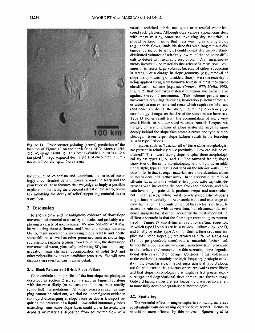
Figure 13. Very high resolution view of breached ridges on the north flank of Ot Mons (•4øN, 216øW, image ß -!
2410037, 9 m pnxel ). The breaches take the form of steep-walled amphitheaters. Terracing within the walls of the amphitheaters might be layering exposed by the amphitheater-forming process. The view is near vertical. Illumi- nation is from the leti. North is down.
33,234 MOORE ET AL.: MASS WASTING ON IO
Figure 14. Preencounter pointing (arrow) prediction of the location of Figure 13 on the north flank of Ot Mons (•-4øN, 215øW, image 1410013). This best available context is a •-2.6 km pixel image acquired during the El4 encounter. Illumi- nation is fi'om the right. North is up.
the product of volcanism and tectonism, the series of seem- ingly circumffential belts or zones beyond the scarp and the plan trace of these tEatums that we judge to imply a possible explanation involving the erosional retreat of the scarp, possi- bly involving the decay of relief-supporting material in the scarp face.
3. Discussion
Io shows clear and unambiguous evidence of downslope movement of material at a variety of scales and probably em- ploying a variety of mechanisms. We now consider what may be producing these difik•rent landtbrms and surtkce textures. On lo, mass movements involving block release and brittle slope tkilure, as well as other processes such as sputtering, sublimation, sapping erosion I?om liquid SO2, the downslope movement of warm, plastically deIbrming SO2 ice, and disag- gregation I¾om chemical decomposition of solid S20 and other polysulfur oxides are candidate processes. We will next discuss these mechanisms in some detail.
3.1. Block Release and Brittle Slope Failure
Characteristic slope profiles of the four slope morphologies described in section 2 are summarized in Figure 17, along with the most likely (or at least the simplest, most readily supported) interpretations. Although processes such as sap- ping cannot be ruled out, we find no unambiguous evidence tbr liquid discharging at slope fiaces or debris transport re- quiring the presence of a liquid. Low-relief hummocky lobes extending from some slope faces could either be avalanche deposits or materials deposited from solid-state flow of a
volatile enriched debris, analogous to terrestrial water-ice- cored rock glaciers. Although observations appear consistent with mass wasting processes involving dry materials, it should be kept in mind that mass wasting involving fluids (e.g., debris flows, landslide deposits with long run-out dis- tances lubricated by a fluid) could potentially involve thinly distributed volumes of relatively low relief that could be diffi- cult to detect with available resolution. "Dry" mass move- ments involve slope materials that release in many small vol- umes or in fewer large volumes because of either a reduction in strength or a change in slope geometry (e.g., removal of slope toe by lowering of a caldera floor). Here the term dry is being applied using a well-known terrestrial mass movement classification scheme [e.g., see Coates, 1977; Malin, 1992, Figure 2] that compares material cohesion and particle size against speed of movement. This scheme groups mass movements requiring fluidizing lubrication (whether from air or water) to one extreme and those which require no lubricant (and hence are dry) at the other. Figure 17 shows how slope morphology changes as the size of the slope fiailure increases. Type D slopes result fi'om the accumulation of many very small, block- or boulder-sized releases fi'om cliff exposures. Larger, coherent fiailures of slope materials reaching more deeply behind the slope fiace create alcoves and type A mor- phology. Even larger slope failures result in the terracing seen in type T slopes.
In places such as Tvashtar all of these slope morphologies are present in relatively close proximity. How can this be ex- plained? The inward facing slopes display three morphologi- cal styles: types U, A, and T. The outward fiacing slopes show two of the same morphologies, A and T, plus an addi- tional style, type D, that is not seen on the interior walls. One possibility is that stronger materials are more abundant closer to the caldera than fiarther away. In this scenario the ratio of silicate lavas to more volatile-rich pyroclastic deposits de- creases with increasing distance fi'om the calderas, and sili- cate lavas might potentially produce steeper and more coher- ent linear scarps, while volatile-rich pyroclastic deposits might tbrm potentially more unstable walls and encourage al- cove tbrmation. The contribution of this fiactor is difficult to
assess or rule out with current data, but circumstantial evi- dence suggests that it is not necessarily the most important. A different scenario is that the tbur slope morphologies summa- rized in Figure 17 also define an evolutionary/time sequence, in which type U slopes are least evolved, tbllowed by type D, and finally by either type A or T. Such a time sequence im- plies that steep slopes (1) are created as cliff-like scarps and (2) then progressively deteriorate as materials fiarther back behind the slope face are weakened somehow fi'om proximity to the surfiace environment. In this scenario, slope degrada- tional style is a t•nction of age. Considering that volcanism at the calderas is certainly the high-frequency geologic activ- ity in the Tvashtar area, it is not surprising that type U slopes are tbund closer to the calderas where renewal is most likely and that slope morphologies that might reflect greater expo- sure age and degradational development are further away. Outward facing slopes are less frequently disturbed so are left to more t•11y develop degradational morphologies.
3.2. Sputtering
The potential effect of magnetospheric sputtering increases substantially with decreasing distance fi'om Jupiter. Hence Io should be most affected by this process. Sputtering at Io

MOORE ET AL.' MASS WASTING ON IO 33,235
Scarp
Figure 15. Very high resolution images (5.5 m pixel 'l, images 2710005 and 2710006) showing a mesa or plateau scarp, largely t•cing away t?om the spacecrat•, and the surface beyond the scarp's tbot (---32øN, 193øW, see context map at top left). Shadow measurements indicate the scarp exhibits -400 m of relief and a slope of-•28 ø. There are hints of layering in the scarp face. While this scene might be entirely the product of volcanism and tectonism, the series of seemingly circumfrential belts or zones beyond the scarp and the plan trace of these t•atures suggest the possibility that it could also be the consequence of erosional retreat of the scarp, possibly involving the decay of relief-supporting material in the scarp face. Original perspective highly oblique (---70ø). Images reprojected to a common point perspective view similar to that fi'om the spacecratL Illumination is t?om the right. North is up.
would have a negligible erosional effect on silicates, such as basalt, and some ett•ct on sulfur allotropes [Johnson, 1990]. Sputtering-induced erosion on Io would be most pronounced on exposures of unprotected SO2 [Johnson, 1990]. As such, the amount of erosion of SO2 due to sputtering over the age of Io's surt•ce (generally accepted as not greater than ---1 Myr [e.g., Johnson and Soderblom, 1982]) determines the maxi- mum erosion sputtering can cause on Io. Johnson [1990], in his summary of sputtering studies, gives a value of 5 x 10 • molecules cm '2 s '• tk)r the maximum sputter erosion rate of SO_, on Io. Over a million years this would result in a surtb. ce lowering of---I m tbr uncontaminated massive SO2 ice (-1.5 g cm '3) or---3 m tbr uncontaminated porous SO2 snow. Surtiace modification on this scale would probably be undetectable even in the highest resolution (-5 m pixel '•) Galileo images of
Io. Thus other processes must dominate landtbrm erosion ob- served by Galileo.
3.3. Sapping
A sapping mechanism involving liquid SO2 was proposed by McCauley et al. [1979] to explain the irregular erosional scarps and bright deposits in layered terrains imaged by Voy- ager 1. Similar morphologies on Earth and Mars have been interpreted as due to the release of water to the surt•ce com- bined with mass wasting [e.g., Carr, 1995]. Liquid water is highly unlikely on Io, but SO2 will become liquid at some depth, depending on the iothermal gradient (probably highly variable in space and time). Artesian pressures would drive liquid SO2 to escape through cracks, fissures, or permeable

33,236 MOORE ET AL.: MASS WASTING ON IO
km
Figure 16. An orthographically projected excerpt from a portion of the right image (image 2710006) in Figure 15 showing what appear to be small gullies (see arrows) cutting into a blander, probably smoother surface. The gul- lies are 10-20 m across and 100-200 m long and are roughly oriented perpendicular to the scarp. Illumination is from above. North is to the left.
layers along the edges of scarps. The escape of SO• to the Ionian surt•ce (-•10 -• bar pressure) would cause vaporization, and an exit velocity of more than 350 m s'•; the SO• would snow back onto the surface up to 70 km from the vent. This is entirely consistent with the diffuse white deposits seen ex- tending from the base of many irregular scarps on Io (see il- lustrations of McCatdey et al. [ 1979]).
As discussed previously, deep alcoves into the plateau near Tvashtar Catena (Figure 1, see A) might have tbrmed by sap- ping. Canyons ---1 km deep [Turtle eta!., this issue] extend up to 40 km into the plateau. The rectangular pattern of alcove- rimmed troughs in the Tvashtar plateau resembles "fi'etted" erosion along the highlands-lowlands boundre3, on Mars. The fi'etted morphology of this part of the Tvashtar plateau might be an example of liquid SO• exploiting and enlarging struc- tural patterns of weakness (e.g., joints and fractures), causing disaggregation and further back wasting into the plateau. Sapping due to liquid water has been proposed tbr the initial channalization of fretted channels on Mars [e.g., Milton, 1973; Cart, 2001]. If the sapping interpretation is correct, this suggests that SO• became liquid at a depth of I km or less when these canyons t•)rmed (perhaps continuing to the pre- sent). However, liquid SO• is modeled to usually occur at depths f•tr below 4 km [Leone and •ilson, 1999], so liquid SO2 at depths _<1 km may not be common. If sapping occurs,
it must rely on locally high geothermal energy to mobilize the liquid SO2. As the Tvashtar region currently is undergoing widespread volcanic activity, such geothermal energy is probably available. New high-resolution images of these canyons are planned lbr the I31 encounter (August 2001) to get a closer look at the morphology and to search for evidence of changes in the canyon walls.
3.4. Plastic Deformation
One of the possible emplacement mechanisms tbr the low- relief lobes extending fi'om alcoves along type A slopes is solid-state flow. This could involve plastic deformation of material with interstitial volatiles (e.g., SO=), somewhat analogous to glacial flow of water ice or ice-cored rock gla- ciers on Earth. Like liquid SO2 sapping, this mechanism also would need a local concentration of geothermal energy to sotlen the SO2 ice. Plastic deformation and "glacial" creep of interstitial water ice has been proposed for the formation of fretted terrain on Mars [e.g., Sharp, 1973; Squyres, 1978; Lucchitta, 1984; Cart, 1995]. It is claimed than in the Mar- tian case plastic det•)rmation of warm water ice would not necessarily cut channels or obviously streamline obstacles, and that ice might simply flow outward onto plains. Analo- gous processes on Io involving a different volatile would leave tEw lasting traces at the resolutions of the Galileo

MOORE ET AL.' MASS WASTING ON IO 33,237
Type U (unmodified) :• ...................... :•'
Figure 17. Stylized profiles of different slope types discussed in the text along with interpretive restorations of their evolu- tion.
Tvashtar and Zal Montes observations, except flow lobes where movement was not topographically restricted. Similar morphologic arguments have been made t•)r the hypothesis that some Martian terrains, such as the fi'etted terrain and large lobate aprons are substantially the result of warm de- forming ice [e.g., Squyres, 1978; Carr, 1995]. An analogous process might be occurring on Io, but with a different "ice" volatile, that of SO2.
Could solid SO2 flow downslope, or simply outward under its own weight, if sufficiently warmed fi'om below? Although experimental stress-strain data lbr solid SO2 is unknown to us, results fi'om recent solid CO2 delbrmation experiments imply that SO2 may behave plastically at temperatures approaching its melting point (198 K). Figure 18 is a plot from Durham et al. [1999] showing the flow of several ices, including their re-
behavior at temperatures normalized by their melting tem- peratures intermediate between H20 and CO2. In any case, H20 is apparently the stifl•st cosmically abundant ice [e.g., Durham et al., 1999]; hence SO2 ice will 11ow more readily than H20 ice at a given fi'action of its melting temperature. As warm H20 ice flows readily over very geologically short timescales, it is reasonable to assume sufficiently warm SO2 ice will also.
3.5. Sublimation Degradation
Sublimation degradation is the result oF disaggregation of relief-lbrming materials through the loss of their cohesive but ultimately volatile, rock-lbrming matrix or cement [Moore et al., 1996]. Sublimation degradation has been proposed as an agent of kilometer-scale landlbrm modification on Io [Moore eta!., 1996] and other Galilean satellites [Moore et al., 1999; Chuang and Greeley, 2000]. Sublimation processes relevant to (noncometary) bodies containing volatiles in their surlhce layers have been modeled by a number of researchers [Lebof- sky, 1975; Purves and Piicher, 1980; Squyres, 1979; Spencer 1987; Colwell et ai., 1990; Moore et al., 1996, 1999].
Moore et ai. [1996], in their pre-Galileo study, proposed that in the case of Io's polar regions (the area of highest- resolution coverage by the Voyager missions) only H2S, sub- limating l?om slopes that lhce the Sun and have thin lags, is volatile enough to cause the observed erosion. They con- cluded that SO2 is not a viable candidate as an agent of ero- sion for high-latitude landtbrms. Models used by Moore et al. [1996], however, did indicate that SO2 might sublimate quickly enough under a very thin (<5 cm), very low albedo (<0.05) lag to modit•y equatorial landtbrms on scales that might be observed in high-resolution(of order of 10 m pixel '•) Galileo images. Moore et ai. [1996] predicted that H2S sur- l•ce ice would be unambiguously detected on Io, particularly at the poles. This prediction, however, has not been borne out.
It is worth noting that a number of observations are consis- tent with the occasional presence of volcanically-released H2S
10'" 1.0
T•,I T Figure 18. Plot from Durham et al. [1999] showing the flow
cent results lbr CO2. Both SO2 and CO2 exhibit van der of several ices. Stress is normalized by the shear modulus (/t.) Waals intermolecular bonding. However, the configuration of and the temperature is normalized by the melting tempera- CO2 molecules is linear, and that of SO2 is not, and so SO2 ture(T,,). SO2 ice flow may fall between that of H20 and will be more polar than CO2. Thus SO2 ice may exhibit flow CO2. See discussion in text.
33,238 MOORE ET AL.: MASS WASTING ON IO
but not stable H2S f¾ost deposits. Nash and Howell [1989] presented spectroscopic evidence fbr the transient occurrence of condensed H2S on lo, but microwave observations f•.iled to detect atmospheric H2S, suggesting abundances below 10 © bar [Le!louch eta!., 1990]. Observations by the Space Tele- scope Imaging Spectrograph (STIS) revealed enhanced H1 Lyman-o½ emission near Io's poles, perhaps due to Iogenic hy- drogen [Roessler eta!., 1999], but detailed analysis of the data has shown that it is reflected solar radiation attenuated by an SO2 atmosphere concentrated near the equator [œeldman e! a!., 2000]. Russell and Kivelson [this issue] present evidence fbr the temporally variable presence of H2S + in Io's exosphere. However, all these H2S sightings give very little support fbr substantial H2S deposits in the near surf•.ce.
As was noted in section 2.5 the amphitheaters among the ridges seen on Ot Mens (Figure 13) are apparently being en- larged by some erosion process, in which case the dark mate- rial seen on their floors may be erosional detritus. The ap- pearance of amphitheater walls is consistent with sublimation- degradation [Moore eta!., 1996, 1999], as are the putatively identified differentially eroded layers seen at high resolution along the SE edge of the Isum plateau (Figure 15). As these features do not appear to be presently associated with local, very low albedo material, the role of SO2 sublimation in their erosion is probably small.
3.6. Disaggregation From Chemical Decomposition
An erosional process that so f•.r has had little discussion in Io studies is disaggregation f¾om thermally induced chemical decomposition. Hapke [1989] and Hapke and Graham [1989] discussed S20 and polysulfur oxide (PSO) and their potential contribution to spectra of Io surf•.ce materials. In the course of explaining why they thought S20 and PSO might be pre- sent on Io's surf•.ce, they reviewed the temperature-dependent behavior of these materials. Hapke [1989] stated that S20 and
the emplacement and subsequent decomposition of S20/PSO- rich layers on timescales compatible with the age of Io's sur- f•.ce and at a size scale that would be within the resolution of
Galileo images. Disaggregation fi'om thermally induced chemical decompo-
sition of solid S20/PSO should degrade landfbrms in a man- ner that resembles erosion f¾om sublimation. If the disaggre- gation-causing heat is primarily solar, typical landfbrms that might be produced are rimless, irregularly shaped pits, un- evenly retreating scarps [e.g., Moore eta!., 1996, 1999] and surfaces reminiscent of glacial ablation surt•tces such as fields of cones or mounds [e.g., Malin and Zimbelman, 1986]. Geethermally induced S20/PSO disaggregation might also fbrm pits, voids, and other collapse features. The erosionally enlarged amphitheaters of the Ot Mens ridge crests (Figure 11) and the putatively identified differentially eroded layering and other surf•.ce textures seen in the along the SE edge of the Isum plateau (Figures 15 and 16) are good candidates fbr ero- sional expressions that are consistent with, though not proof of, S20/PSO disaggregation. The S20/PSO disaggregation hypothesis, however, is an intriguing explanation fbr ero- sional morphologies on Io, which could be attributable to sublimation but are not so ascribed due to the absence of a
suitable volatile.
3.7. Implications for Volatile Abundances in Io's Upper Crust
Both the eroded layered terrain and the long-lived Prome- theus-type plumes indicate that the upper crust of Io is rich in volatiles. Hapke [1989] proposed a model in which surface of Io is dominantly basaltic with only thin (---1 lum) coatings of PSO, S:O, and SO2, but McEwen and Lunine [1990] protested that such a model could not account tbr the volcanic activity and that volatiles must be much more abundant in Io's upper crust. This view is strengthened by evidence that Prome-
PSO could be fbrmed when SO2 gas is exposed to a dissocia- theus-type plumes are produced by interactions between sill- tive environment such as the high temperatures associated with hot erupting magma. Recent observations [McEwen e! al., 1998] of very hot magmas on Io imply that the conditions fbr S20 and PSO fbrmation •.nd deposition exist and may be common. Hapke [1989] notes that S20 is stable if the tem- perature is less than about 115 K. As the temperature rises above this value, solid SO2 does not sublimate directly but in- stead disproportionates into S:O and PSO. Hapke [1989] goes on to note that the transition t¾om S•_O to PSO does not occur at a fixed temperature but over a range fi'om -115 to ---170 K. Hapke and Graham [1989] report that PSO can fbrm on surfaces with temperatures as high as 300 K, and it can exist in a lnetastable state even at this temperature fbr months. Hapke [1989] comments that as the temperature rises fi'om 115 K, PSO repolymerizes continuously into chains of in- creased S:O ratio, with attendant production of copious quan- tities of SO2 and a considerable decrease in volume. Thus as PSO warms it disaggregates.
-1
Hapke [1989] estimates that globally as much as 50 •tm yr of S20 from volcanoes may be deposited on Io, which would result in a layer 5 cm thick in 103 years. Much thicker depos- its might be expected in the vicinity of a long-erupting vol- cano. The S20/PSO deposits would probably be interlayered with dust-sized sulfur and silicate particles. S20/PSO-rich deposits could be susceptible to decomposition over a wide range of temperatures both due to solar insolation and geo- thermal heating. The rates of this decomposition would allow
cate lava and near-surface SO2 or sulfur in the surrounding plains extending hundreds of kilometers fi'om the primary vents [McEwen eta!., 1998; Kieffer eta!., 2000; Milazzo e! a!., this issue]. The eroded layered terrain imaged by Voy- ager in Io's south polar region also suggests a volatile-rich composition because the plateau materials appear to be com- pletely removed in some manner [Schaber, 1982]. The high- resolution Galileo images support this impression, as dis- cussed above. Both the Galileo and Voyager observations suggest more voluminous removal of plateau materials at high latitudes, but the low Sun images near the equator are very limited in coverage. We should expect greater volatiles at high latitudes where the surt•ce is coolel', and this view is supported by mapping of tbrward scattering surface units in- terpreted as fi'esh SO2 fi'ost [Geissler eta!., this issue]. The Prometheus-type plumes have an equatorial concentration, but this is probably controlled by the lava eruption styles [McE- •ven eta!., 2000]. However', note that there are many long- lived eruptions that do not produce plumes, so presumably the upper crust has been depleted of volatiles in these regions. In summary, the evidence suggests that Io's upper crust is rich in volatiles, at least in places, at all latitudes.
4. Conclusions
1. We recognize foul' major slope types observed on a number of intermediate resolution (-250 m pixel '•) images

MOORE ET AL.: MASS WASTING ON IO 33,239
and several additional textures on very high resolution (-10 m pixel -•) images. Slopes and scarps on Io ohen show evidence of erosion, seen in the simplest tbrm as alcove-arving slumps and slides at all scales. Many steep slopes on Io probably de- grade through dry mass-wasting processes such as block re- lease and brittle slope t•ilure.
2. Sputtering probably plays no role in the erosion of Io's surface at the scale seen even in the highest-resolution im- ages.
3. A sapping mechanism involving liquid SO,,, proposed by McCauley et al. [1979] to explain the irregular erosional scarps and bright deposits in layered terrains imaged by Voy- ager 1, may have ibrmed the rectangular pattern of alcove- rimmed troughs in the Tvashtar plateau (classified as a mani- festation of type A slopes in this paper), which resemble fi'et- ted plateau erosion on Mars. If the sapping explanation is correct, this suggests that SO2 became liquid at a depth of 1 km or less when these canyons ibrmed (perhaps continuing to the present). If sapping is, in thct, taking place, it must rely on locally high geothermal energy to mobilize the liquid SO2.
4. Fretted erosion along portions of the Tvashtar plateau could also reflect plastic detbrmation and glacial flow of in- terstitial volatiles (e.g., SO2) that exploit and enlarge struc- tural patterns of weakness (e.g..joints and fi'actures), causing disaggregation and t•rther back wasting into the plateau. This mechanism also relies on locally high geothermal energy to mobilize the volatile. Alcoves with lobes emerging from them seen elsewhere on the satellite may have tbrmed in a similar manner.
5. The appearance of some slopes and near-slope surface textures seen in very high resolution images is consistent with erosional styles that could be attributed to sublimation- degradation. However, it is difiScult to identi(y a suitable volatile (e.g., H2S) that can sublimate lhst enough to alter Io's youthful surt:ace.
6. Disaggregation from chemical decomposition of solid S20 and other polysult•r oxides may conceivably operate on Io. This mechanism could degrade landtbrms in a manner that resembles degradation from sublimation and at a rate comparable to that of resurthcing.
Acknowledgements. This investigation was funded by NASA's Galileo Project. We are grateful ibr the comments of an anonymous reviewer. Thanks goes to Pam Engebretson for her help with figure preparation.
References
Bakker, J.P., and J.W.N. Le Heux, A remarkable new geomophologi- cal law, Proc. K. Ned. Akade. Wet., Ser. B Phys. Sci., 55, 399- 410, 554-571, 1952.
Cart, M.H., The Martian drainage system and the origin of networks and fi'etted channels, d. Geophys. Res., 100, 7479-7507, 1995.
Cart, M.H., Mars Global Surveyor observations of Martian fretted terrain, d. Geophys. Res., in press, 2001.
Chuang, F.C., and R. Greeley, Large mass movements on Callisto, d. Geophys. Res., 10.5, 20,227-20,244, 2000.
Coates, D.R., Landslide perspectives, Rev. Eng. Geol., 3, 3-28, 1977. Colwell, J.E., B.M. Jakosky, B.J. Sandor, and S.A. Stern, Evolution
of topography on comets. II. Icy craters and trenches, Icaurs, 85, 205-215, 1990.
Durham, W.B., S.H. Kirby, and L.A. Stern, Steady-state flow of solid CO2: Preliminary results, Geophys. Res. Lett., 26, 3493-3496, 1999.
Feldman, P.D., D.F. Strobel, H.W. Moos, K.D. Retherford, B.C. Wolven, M.A. McGrath, F.L. Roesler, R.C. Woodward, R.J. Oliv-
ersen, and G.E. Ballester, Lyman-•: imaging of the SO2 distribu- tion on Io, Geophys. Res. Lett., 27, 1787-1790, 2000.
Geissler, P., A. McEwen, C. Phillips, D. SimoneIll, R. Lopes-Gautier, and S. Doute, Galileo imaging of SO2 frosts on Io, d. Geophys. Res., this issue.
Hapke, B., The surt•tce of Io: A new model, Icarus, 79, 56-74, 1989. Hapke, B., and F. Graham, Spectral properties of condensed phases
of disulthr monoxide, polysulfur oxide, and irradiated sulfur, Ica- rus, 79, 47-55, 1989.
Johnson, R.E., Energetic Charged-Particle Interactions with Atmos- pheres and Surfaces, Phys. Chem. Space, vol. 19, 232 pp., Springer-Verlag, New York, 1990.
Johnson, T.V., and L.A. Soderblom, Volcanic eruptions on Io: Im- plications tbr surt•tce evolution and mass loss, in Satellites of Ju- piter, edited by D. Morrison, pp. 634-646, Univ. of Ariz. Press, Tucson, 1982.
Johnson, T.V., D.L. Matson, D.L. Blaney, G.J. Veeder, and A. Da- vies, Stealth plumes on Io, Geophys. Res. Lett., 22, 3293-3296, 1995.
Kieffer, S.W., R. Lopes-Gautier, A. McEwen, W. Smythe, L. Kesz- thelyi, and R. Carlson, Prometheus: Io's wandering plume, Sci- ence, 288, 1204-1208, 2000.
Klaasen, K.P., et al., Calibration and performance of the Galileo Solid-State hnaging system in Jupiter orbit, Opt. Eng., 38, 1178- 1199, 1999.
Lebofsky, L.A., Stability of frosts in the solar system, Icarus, 25, 205-217, 1975.
Lellouch, E., M. Belton, I. de Pater, S. Gulkis, and T. Encrenaz, Io's atmosphere from microwave detection of SO2, Nature, 346, 639- 641, 1990.
Leone, G., and L. Wilson, The geothermal gradient of Io, Lunar Planet. Sci. [CD-ROM], ,YX,¾, Abstract 1358, 1999.
Lucchitta, B.K., Ice and debris in the fretted terrain, Mars, Proc. Lu- nar Planet. Sci. Conf 14 •', Part 2, d. Geophys. Res., 89, suppl., B409-B418, 1984.
Malin, M.C., Mass movements on Venus: Preliminary results from Magellan cycle I observations, d. Geophys. Res., 97, 16,337- 16,352, 1992.
Malin, M.C., and D. Dzurisin, Landform degradation on Mercury, the Moon, and Mars: Evidence from crater depth/diameter relation- ships, d. Geophys. Res., 82, 376-388, 1977.
Malin, M.C., and J.R. Zimbelman, Surface morphology of cometary nuclei, Lunar Planet. Sci., XVII, 512-513, 1986.
McCauley, J.F., B.A. Smith, and L.A. Soderblom, Erosional scarps on Io, Nature, 280, 736-738, 1979.
McEwen, A.S., and J.I. Lunine, Comment on "The surt•tce of Io: A new model" by Bruce Hapke, Icarus, 84, 268-274, 1990.
McEwen, A.S., et al., High-telnperature silicate volcanism on Jupi- ter's moon Io, Science, 281, 87-90, 1998.
McEwen, A.S., et al., Galileo at Io: Results from high-resolution im- aging, Science, 288, 1193-1198, 2000.
Milizzo, M.P., L.P. Keszthelyi, and A.S. McEwen, Observations and initial modeling of lava-SO2 interactions at Prometheus, Io, d. Geophys. Res., this issue.
Milton, D.J., Water and processes of degradation in the Martian land- scape, d. Geophys. Res., 78, 4037-4047, 1973.
Moore, J.M., M.T. Mellon, and A.P. Zent, Mass wasting and ground collapse in terrains of volatile-rich deposits as a solar system-wide geological process: The pre-Galileo view, Icarus, 122, 63-78, 1996.
Moore, J.M., et al., Mass lnovement and landtbrm degradation on the icy Galilean satellites: Results from the Galileo nominal mission, Icarus, 140, 294-312, 1999.
Nash D.B., and R.R. Howell, Hydrogen sulfide on Io: Evidence from telescopic and laboratory int?ared spectra, Science 244, 454-457, 1989.
?appalardo, R. T., and R. Greeley, A review of the origins of sub- parallel ridges and troughs: Generalized morphological predic- tions from terrestrial models, d. Geophys. Res., 100, 18,985- 19,007, 1995.
Purves, N.G., and C.B. Pilcher, Thermal migration of water on the Galilean satellites, Icarus, 43, 51-55, 1980.
Radebaugh, J., L.P. Keszthelyi, A. S. McEwen, E.P. Turtle, W.L. Jaeger, M. Milazzo, and the Galileo SSI Team, ?aterae on Io: A new type of volcanic caldera?, d. Geophys. Res., this issue.
Roessler, F.L., H.W. Moos, R.J. Oliversen, R.C. Woodward Jr., K.D. Retherford, F. Scherb, M.A. McGrath, W.H. Smyth, P.D. Feld-

33,240 MOORE ET AL.: MASS WASTING ON IO
man, and D.F. Strobel, Far-ultraviolet imaging spectroscopy of Io's atmosphere with HST/STIS, Science 283, 353-357, 1999.
Russell, C.T., and M.G. Kivelson, Evidence for sulfer dioxide, suitor monoxider, and hydrogen sulfide in the Io exosphere, J. Geophys. Res., this issue.
Schaber, G.G., The geology of Io, in Satellites of Jupiter, edited by D. Morrison, pp. 556-597, Univ. of Ariz. Press, Tucson, 1982.
Schenk, P.M., and M.H. Bulmer, Origin of mountains on Io by thrust faulting and large-scale mass movements, Science, 279, 1514- 1517, 1998.
Selby, M. J., Hillslope Materials and Processes, 2nd ed., pp. 365- 369, Oxford Univ. Press, New York, 1993.
Sharp, R.P., Mars: Fretted and chaotic terrains, d. Geophys. Res., 78, 4073-4083, 1973.
Sharpe, C.F.S., Landslides and Related Phenomena, 137 pp., Cooper Square, New York, 1939.
Spencer, J.R., Thermal segregation of water ice on the Galilean sat- ellites, Icarus, 69, 297-313, 1987.
Squyres, S.W., Martian fretted terrain: Flow of erosional debris, Ica- rus, 34, 600-613, 1978.
Squyres, S.W., The evolution of dust deposits in the Martian north polar region, Icarus, 40, 244-261, 1979.
Turtle, E. P., et al., Mountains on Io: High-resolution Galileo obser- vations, initial interpretations, and formation models, J. Geophys. Res., this issue.
Varnes, D.J., Landslide types and processes, in Landslides and Engi- neering Practice, edited by E.B. Eckel, pp. 20-47, Nat. Acad. of Sci., Nat. Res. Counc. Highway Res. Board, Washington, D.C., 1958.
Varnes, D.J., Slope movement types and processes, in Landslide,
Analysis, and Control, edited by R.L. Shuster and R.J. Kriszek, pp. 11-33, Nat. Acad. of Sci., Nat. Res. Counc. Transp. Res. Board, Washington, D.C., 1978.
F.C. Chuang, Department of Geological Sciences, Arizona State University, Tempe, AZ 85287.
J.W. Head Ill and B.E. Nixon, Department of Geological Sciences, Brown University, Box 1846, Providence, RI 02912. (j ames _head_I I I • br own. ed u)
A.S. McEwen, M. Milazzo, and E.P. Turtle, Lunar and Planetary Laboratory, University of Arizona, 1629 East University Blvd., Tucson, AZ 85721. (mcewen•pirl.lpl.arizona.edu; mmilazzo•pirlmail.lpl. arizona.edu; turtle•pirlmail.lpl.arizona. edu)
J.M. Moore, Space Sciences Division, NASA Ames Research Center, MS 245-3, Moffett Field, CA 94035-1000. ([email protected]. gov)
R.T. Pappalardo, Astrophysical and Planetary Sciences Department, Campus Box 392, University of Colorado, Boulder, CO 80309-0392. (pappalardo•lasp.colorado.edu)
P.M. Schenk, Lunar and Planetary Institute, 3600 Bay Area Boulevard, Houston, TX 77058. (schenk•lpi.usra.edu)
R.J. Sullivan, Center tbr Radiophysics and Space Research, Cornell University, 308 Space Sciences Building, Ithaca, NY 14853- 6801. (sullivan•cuspi f. tn. cornell.edu)
(Received September 5, 2000; revised February 15, 2001; accepted March 12, 2001.)