lake istokpoga observatory
TRANSCRIPT
Lake Istokpoga Observatory
(Rev. 28 Oct 2020)
After serving in the U.S. Air Force for eight years and six more years traveling as an engineer for a company in up-state New York our family was more than ready to settle down. We moved to Miami, Florida where we lived for 24 years.
My interest in astronomy goes back to my youth but never had the time to actually pursue the hobby. In early 1973 my wife gave me a 60mm Tasco for Christmas to observe comet Kohoutek and that was enough to renew my interest in astronomy and telescopes. I continued to use my tiny Tasco to observe with in the Everglades and then built a couple small telescopes from kits.
At least the hobby would lead me to meet friendly people and eventually this would help when a job change was imminent. My first amateur telescope making project, with the help of our mid-night foreman at work, enabled me build a small Newtonian from a kit. After a couple more attempts making telescopes the local club encouraged me build a larger instrument and so on. While working nightshift we would go up on the roof of our 8-story building during breaks or lunch time to observe. The roof had high walls and was secure, so three of us put telescopes up there to stay. Over those years, until hurricane Andrew nearly blew us off the map, we made a lot of telescopes and I still have three of them.
After moving to Miami in early 1973 I visited the Miami Museum and Space Transit Planetarium where I met some Southern Cross Astronomical Society (S.C.A.S.) folks, including the president of the Society, Bill Douglass. They invited me to their monthly meeting and use their observatory on the roof of the museum. I returned occasionally and began to attend the monthly meetings until 1986 when the SCAS moved to the Florida International University and I slowly slacked off participating in the early 1990’s.
Shortly after joining the SCAS I bought an 8” SCT and began to observe more often. The SCAS had a great Amateur Telescope Making (ATM) group, so in the mid-1970’s I set out to build some moderate sized telescopes and then bought a 6” f/4 from a member, Bobby Riefer, to use for astrophotography. Not much to say about this telescope except it was first owned by a local Miami amateur and then me and some years later I gave it to my son and, then when he went off to the Navy he sold it to a friend who sold it to a friend of mine and then he gave it back to me!
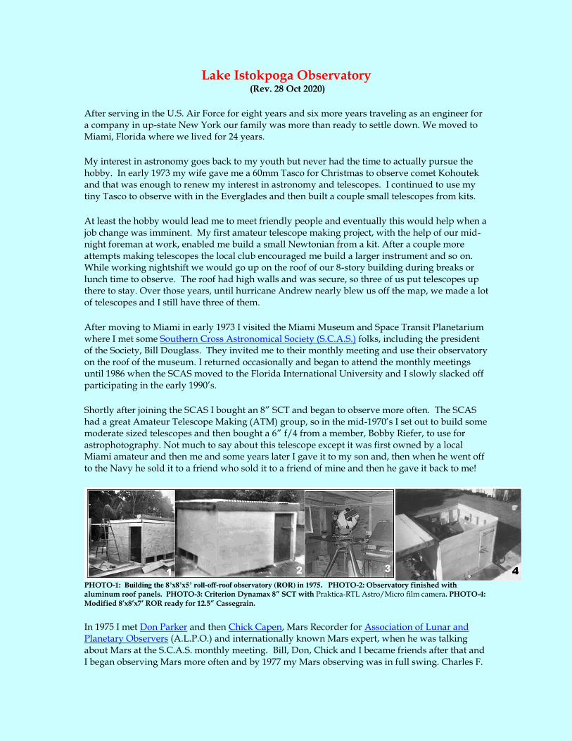
PHOTO-1: Building the 8’x8’x5’ roll-off-roof observatory (ROR) in 1975. PHOTO-2: Observatory finished with aluminum roof panels. PHOTO-3: Criterion Dynamax 8” SCT with Praktica-RTL Astro/Micro film camera. PHOTO-4: Modified 8’x8’x7’ ROR ready for 12.5” Cassegrain.
In 1975 I met Don Parker and then Chick Capen, Mars Recorder for Association of Lunar and Planetary Observers (A.L.P.O.) and internationally known Mars expert, when he was talking about Mars at the S.C.A.S. monthly meeting. Bill, Don, Chick and I became friends after that and I began observing Mars more often and by 1977 my Mars observing was in full swing. Charles F.

("Chick") Capen gave a second talk on Mars at the Southern Cross Astronomical Society meeting in February 1979 and urged both Parker and me to help him with the A.L.P.O. Mars Section. We had been contributing observations to him for a few years and soon thereafter we both became assistant Mars Recorders. After talking with Chick about his life I suddenly remembered his name in an old book that I had from my high school days, Men, Rockets, and Space Rats, [Lloyd Mallan, (C)1955, Pub. Julian Messner, Inc., pp50, 51-54] and [Secrets of Space Flight, Lloyd Mallan, (C)1956, pp45, 94]. These books had a great influence on me and may have changed my life.
Evolution of the 6-inch f/4 Newtonian Telescope
Since I acquired this telescope from Robby Riefer in 1975 almost everything on this scope has been replaced or refigured. A simple fast Newtonian with a 24.25” (615.95 mm) focal length primary and was refigured by Richard A. Fagin sometimes in the 1970’s. Originally it was on an Edmunds Scientific 85-108 equatorial mount and wooden tripod with no motor drive. Then attached to Parks heavy equatorial mount and steel pier with a Mathis 10” polar drive fitted with a home made plate and attachment hardware to the end of the polar axis. It is now mounted onto a “Chicago Mount,” as we called them made by Al Novak, and has a Mathis 8.40” polar drive.
Evolution of the 6” f/4 telescope: 1975, 1980, 2001, 2008. LEFT: 6” f/4 in 1975. CENTER-LEFT: Refigured primary mirror and refurbished. CENTER-RIGHT: New aluminum tube. RIGHT: Mounted on the so-called “Chicago Mount” that is used by a neighbor for Lunar and deep sky observing and me for Solar Observing. This drive features a Thomas Mathis 8.40-inch worm gear drive using a 1/2-RPM Hurst motor [Transmission ratio: (20/54) (1/266) = 0.5 / 718.2 = 1 / 1436.4].
Using a Sky Instruments' AE-FOCH is a 2-inch x 0.75" high helical focuser (plus 0.25”) with an E & W Optical, Inc. 1.5-inch quartz secondary mirror. This mirror was glued to an aluminum tube machined to fit the spider and holder collimating block with the end machined to 45 degrees. Eliminating the secondary holder shell the clear aperture becomes 1.5” (25% obstruction) yielding a linear image diameter of 0.4571-inch (1.1-degree field) at the focal point with a contrast factor (CF) of 2.64:1. (NOTE: an unobstructed telescope yields a CF of 5.25 : 1). This is mounted to a thin wall, 7.125-inch O.D. aluminum tube (7” inside diameter)," then the secondary to focal point distance of 4.5625 inches. [See: Design a Newtonian Telescope. Also, go see Mel Bartel's neat site: Diagonal Off-Axis Illumination Calculator ].

LEFT: The 1.5-inch secondary mirror in holder with no overlap rim. RIGHT: Mel Bartels’ Secondary Mirror Off-Axis
Illumination Diagram
The secondary section contains Novak secondary support (spider) and secondary mirror holder, a 1.5-inch fused Quartz secondary mirror from an old optical company, E & W Optical, Inc., and Orion low profile helical focuser. The primary section has a 6 x 1-inch Pyrex mirror refigured by Richard Fagin and Novak primary cell.
The old configuration using a 1.83”secondary (30.5% obstruction) yielded a linear image diameter of
0.9166-inch (2.2-degree field) at the focal point with a contrast factor (CF) of 1.97:1. For Solar Observing I use the 6” f/4 with a full aperture Baader Solar Filter. At times I attached the solar filter to cardboard aperture mask to use on my larger telescope and serves to shade the observer from the Sun.

Nothing fancy around here; for Solar observing with either the 6” telescope this Baader
Solar Filter setup works fine. RIGHT: Rebuilt mount.

12.5-INCH CASSEGRAIN TELESCOPE OPTICAL DESIGN
By the late 1970’s our motley group of telescope makers to the SCAS began to experiment with different types of telescopes and I then built a 12.5-inch f/16.5 Cassegrain reflector. The optics
were made by our local optician, Richard Fagin. I also increased the height of my 8’x8’ roll-off-
roof observatory on our back patio to accommodate the larger telescope. The aluminum roof panels were replaced with wood and tar paper then painted with “Thermal-Coat, Latex acrylic paint” that rendered the observatory much cooler during the day time.
LEFT: My first 12.5” f/16.5 Cassegrain telescope in the roll-off roof observatory with Chick Capen and others. RIGHT:
Modified 12.5” f/30 Cassegrain telescope with aluminum tube.
The first version of the 12.5” f/16.5 Classical Cassegrain performed fairly well however, the heavy fiberglass tube would hold heat for a long time and then develop tube currents, so observing with this arrangement was difficult to say the least. Also, it had a large 3.5” secondary mirror that reduced image contrast, so Fagin made a new 1.97” secondary mirror figured for a longer effective focal ratio, to f/30, and shorter back focus. After replacing the 38-lb fiberglass tube with a 16-lb thin-wall aluminum tube the heat problems went away and the telescope would be ready for use within a few minutes of opening up the observatory. Tube assembly weight 57 pounds.

Cut away diagram of final results for the 12.5-inch f/4 – f/30 system: a 16% obstruction from the secondary mirror delivering
0.8794-inch linear image field (484 arcsec) with a contrast factor (CF) of 3.77 : 1, whereas a CF of 5.25 : 1 is an unobstructed
system. . NOTE: contrast factor is discussed later in this article.
The Equatorial Mount: This Park’s mount was cast from aluminum and came with 1.5-inch chromium steel shafts. The polar assembly has 0.5"x 6" flanges at the top end and after milling a circular area in the flange a Timken bearing was installed. The rear end of the housing was milled to fit a Timken bearing. Also, the top and bottom of the declination housing did not have enough material to install bearings so I added a thin disk of Teflon (0.03" thick) to the bottom to separate these surfaces to act as a bearing. Then a 3/8th-inch aluminum disk was machined to fit the shaft in the 0.5"x 6" flange at the top of the declination shaft and bolted to the flange with a ball bearing inserted between the flange and the aluminum disk. A thin sheet Teflon as inserted between the flanges to stabilize the declination axis. The Teflon surface provided roller bearing smoothness anyway. The pier is a 6” OD x 48” H water pipe and mount weighs approximately 183 pounds.
Using a discarded 1-pound, 6” diameter coffee can and a centered 1.5” wooden dowel lead was melted and poured into the can to 5.75” high to form a counterweight and another to 2.5” high. Both counterweights were used and weighed 89 pounds. The telescope tube center of gravity is about 14 inches from the primary end. The 19-long saddle has been completely made with wood and reinforced with 1/2-inch steel rods to tighten the saddle base.
.
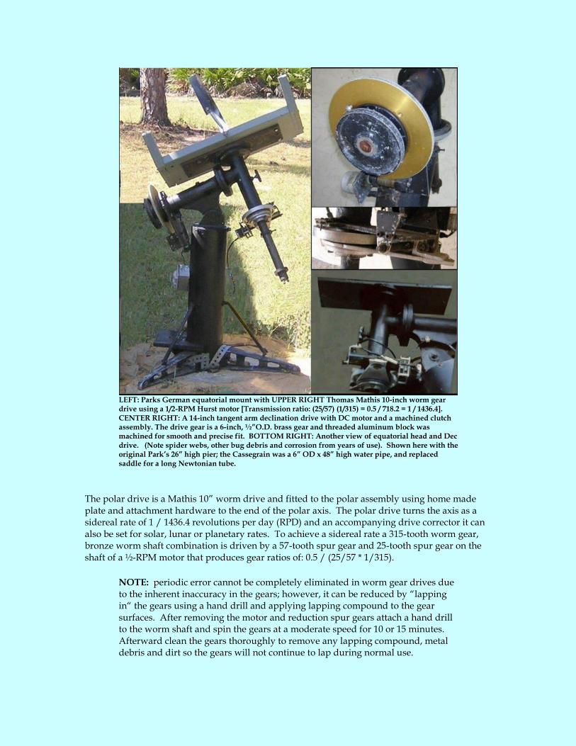
LEFT: Parks German equatorial mount with UPPER RIGHT Thomas Mathis 10-inch worm gear drive using a 1/2-RPM Hurst motor [Transmission ratio: (25/57) (1/315) = 0.5 / 718.2 = 1 / 1436.4]. CENTER RIGHT: A 14-inch tangent arm declination drive with DC motor and a machined clutch assembly. The drive gear is a 6-inch, ½”O.D. brass gear and threaded aluminum block was machined for smooth and precise fit. BOTTOM RIGHT: Another view of equatorial head and Dec drive. (Note spider webs, other bug debris and corrosion from years of use). Shown here with the original Park’s 26” high pier; the Cassegrain was a 6” OD x 48” high water pipe, and replaced saddle for a long Newtonian tube.
The polar drive is a Mathis 10” worm drive and fitted to the polar assembly using home made plate and attachment hardware to the end of the polar axis. The polar drive turns the axis as a sidereal rate of 1 / 1436.4 revolutions per day (RPD) and an accompanying drive corrector it can also be set for solar, lunar or planetary rates. To achieve a sidereal rate a 315-tooth worm gear, bronze worm shaft combination is driven by a 57-tooth spur gear and 25-tooth spur gear on the shaft of a ½-RPM motor that produces gear ratios of: 0.5 / (25/57 * 1/315).
NOTE: periodic error cannot be completely eliminated in worm gear drives due to the inherent inaccuracy in the gears; however, it can be reduced by “lapping in“ the gears using a hand drill and applying lapping compound to the gear surfaces. After removing the motor and reduction spur gears attach a hand drill to the worm shaft and spin the gears at a moderate speed for 10 or 15 minutes. Afterward clean the gears thoroughly to remove any lapping compound, metal debris and dirt so the gears will not continue to lap during normal use.

Also, a 14-inch radius tangent arm declination drive was machined using scarp metal. The tangent arm slips into the adjustable aluminum/cork clutch assembly and attached to the declination shaft. A ½”- 13 screw was machined from braze stock to fit inside a threaded aluminum block and associated hardware to drive the arm back and forth to adjust the declination axis. To avoid backlash and to move the axis north or south a 3/8th-inch hardened bolt is tightly fitted into a slot milled in the tangent arm end. A DC motor and homemade reduction gear box for designed for a 7-arcsec/minute drive rate. Some of the materials used in this drive were scrape aluminum metal and components left over from old flight simulator modifications. This drive has operated successfully for nearly three decades and still works fine today.
Around that time period I began building electronic telescope drive correctors to control the polar axis speed and made several for myself and friends. The first units were made similar to the popular “Saxton circuit” that was available from Willmann-Bell [Saxton, 1975] and later modified by me for better stability and DC outputs for declination control. This unit is still in use today after more than 35 years use.
Capt. Vernon P. Saxon Electronic Speed Control for Clock Drives as described in the January 1975
S&T, pages 50-52.
12.5-INCH NEWTONIAN TELESCOPE OPTICAL DESIGN
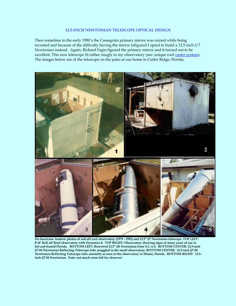
Then sometime in the early 1980’s the Cassegrain primary mirror was ruined while being recoated and because of the difficulty having the mirror refigured I opted to build a 12.5-inch f/7 Newtonian instead. Again, Richard Fagin figured the primary mirror and it turned out to be excellent. This new telescope fit rather snugly in my observatory (see: unique roof caster system). The images below are of the telescope on the patio at our home in Cutler Ridge, Florida.
Pre hurricane Andrew photos of roll-off roof observatory (1979 - 1992) and 12.5” f/7 Newtonian telescope. TOP LEFT: 8’x8’ Roll off Roof observatory with Dynamics 8. TOP RIGHT: Observatory showing signs of many years of use in hot and humid Florida. BOTTOM LEFT: Borrowed 12.5” f/6 Newtonian from S.C.A.S. BOTTOM CENTER: 12.5-inch f/7.04 Newtonian Reflecting Telescope tube snuggled in the small observatory. BOTTOM CENTER: 12.5-inch f/7.04 Newtonian Reflecting Telescope tube assembly as seen in the observatory in Miami, Florida. BOTTOM RIGHT: 12.5-inch f/7.04 Newtonian. Note: not much room left for observer!

The 12.5-inch f/7 Newtonian can be seen in the figure below. It was made from a 15.125-inch O.D. by 92" long thin wall (0.060) aluminum tube rolled and welded by a local business. A local aircraft salvage yard supplied the precision-machined titanium jet engine rings used as end supports for tube. These rings also help conform the tube and make centering of the tube components very easy. The entire tube is lined with 1/8th-inch cork purchased from a local hardware store and glued in place then painted flat black. The cork lining helps insulate the inside of the telescope from tube currents and also provides a rough finish to reduce light scatter.
A Park’s German equatorial mount that was purchased back in the mid-1970’s for a 12.5" f/30 Cassegrain discussed in the above and subsequently used for this 12.5" f/7 Newtonian with a shorter pier tube. The focuser stands 6.8 feet (92 inches) from the ground and requires a 6-foot ladder or platform to reach the focuser. The 12.5-inch diameter (88-inch focal length) primary for this telescope was made by a local optician Richard Fagin. The total weight of the tube assembly is 74 pounds that includes misc hardware, the finder and rings, titanium end rings, secondary, holder and spider, primary mirror and cell with aluminum tube, cork and glue. Total OTA and saddle weighs 94 pounds.
12.5-inch f/7.04 Newtonian Telescope on Parks mount in Lake Placid, Florida.
The low profile helical focuser with 1-1/4” adapter, primary cell, secondary holder and spider were purchased from Kenneth F. Novak & Co. If this focuser is mounted on the outside of the tube the minimum height and adapter is 1.25”. In this configuration the distance from secondary mirror to focal plane in this tube would have been 9.0625” (add 0.25”); but to reduce the height by more than ½-inch the focuser was mounted from the inside of the telescope tube resulting in a focuser height of only 0.75” (+0.25”) and rendering secondary mirror to focal plane to 8.3125” + 0.25” for 8.5625” (See Figure below). A word of caution: make sure the inside drawtube does

interfere with the optical path when mounting any focuser on a Newtonian telescope. The 1.52-inch quartz secondary was purchased from E & W Optical, Inc. and the secondary holder rim was milled down from 0.125” to 0.03125” resulting in a clear aperture of 1.4575”. The linear image diameter is 0.2672-inch (10.4-arcmin) with a contrast factor (CF) of 4.19 : 1
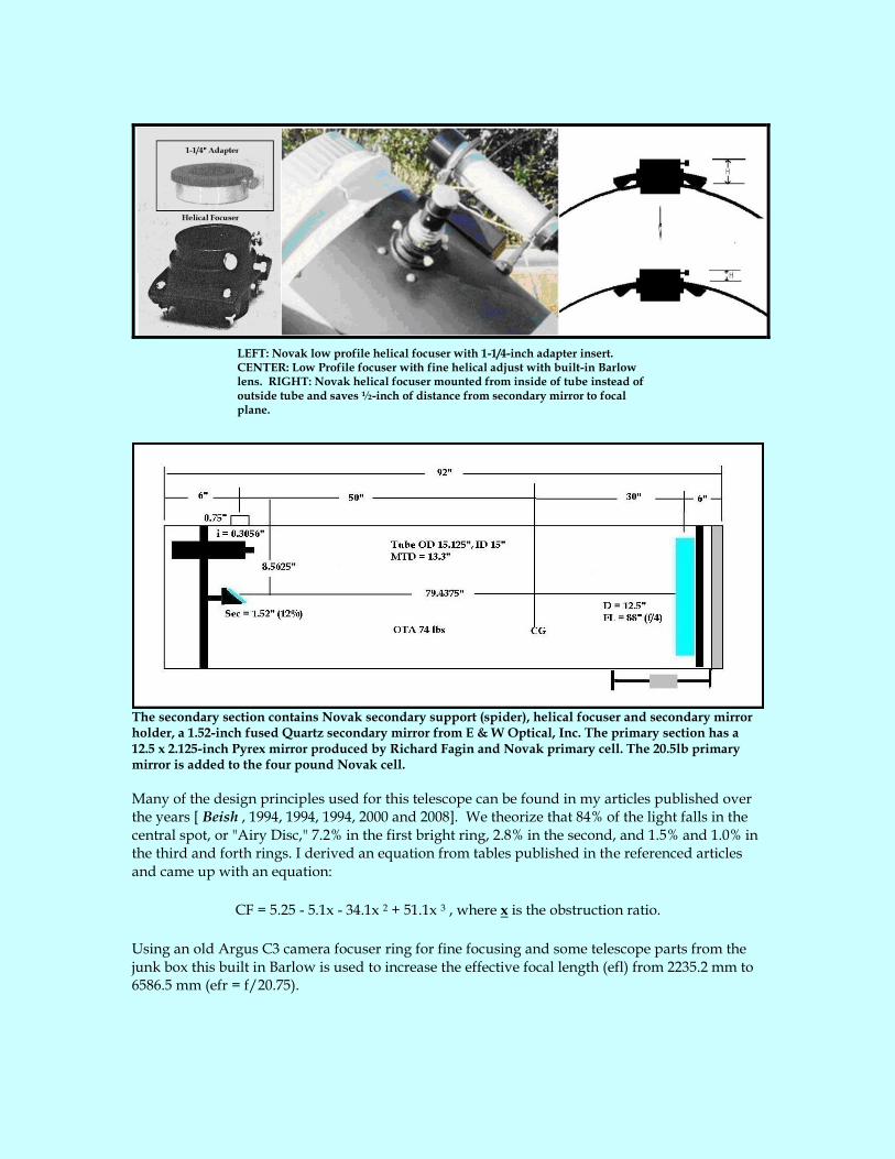
LEFT: Novak low profile helical focuser with 1-1/4-inch adapter insert. CENTER: Low Profile focuser with fine helical adjust with built-in Barlow lens. RIGHT: Novak helical focuser mounted from inside of tube instead of outside tube and saves ½-inch of distance from secondary mirror to focal plane.
The secondary section contains Novak secondary support (spider), helical focuser and secondary mirror holder, a 1.52-inch fused Quartz secondary mirror from E & W Optical, Inc. The primary section has a 12.5 x 2.125-inch Pyrex mirror produced by Richard Fagin and Novak primary cell. The 20.5lb primary mirror is added to the four pound Novak cell.
Many of the design principles used for this telescope can be found in my articles published over the years [ Beish , 1994, 1994, 1994, 2000 and 2008]. We theorize that 84% of the light falls in the central spot, or "Airy Disc," 7.2% in the first bright ring, 2.8% in the second, and 1.5% and 1.0% in the third and forth rings. I derived an equation from tables published in the referenced articles and came up with an equation:
CF = 5.25 - 5.1x - 34.1x 2 + 51.1x 3 , where x is the obstruction ratio.
Using an old Argus C3 camera focuser ring for fine focusing and some telescope parts from the junk box this built in Barlow is used to increase the effective focal length (efl) from 2235.2 mm to 6586.5 mm (efr = f/20.75).

LEFT: Drawing of built-in Barlow lens and Argus C3 focusing ring. CENTER: Photo of built-in
Barlow lens that fits into Novak helical focuser with 1-1.4-inch adapter removed. RIGHT: Baader Solar Filter with cardboard mask for 12.5” tube.
The Equatorial Mount: The equatorial head is the same as the Park’s mount described in 12.5” f/30 Cassegrain telescope section above except with the original 26” high pier. The telescope tube center of gravity is about 30 inches from the primary end. The 30-long saddle has been completely made with wood and reinforced with 1/2-inch steel rods to tighten the saddle base. The saddle and pier is a 6” OD x 26” tall steel pipe and mount weighs approximately 158 pounds.
LEFT: Accutrack Model 4402 Drive Corrector. Selected and variable A/C output for RA drive and switched DC output for declination drive. RIGHT: Saxon Electronic Speed Control used for the
Cassegrain telescope.

16-INCH TELESCOPE OPTICAL DESIGN
My larger Mars observing instrument is a simple truss tube 16-inch f/6.91 Newtonian telescope (110.5-inch focal length) that I began to build sometime in late 1987 and was completed sometime in early 1991. I chose a light weight simple truss tube design because of the good thermal tracking, light weight and aesthetic appeal. The light shield is thin aluminum flashing material wrapped inside and screwed to the trusses.
New 16-inch, 110.5-inch focal length Newtonian (f/6.9) mounted onto old home backyard patio. Shown in
Cutler Ridge, Florida observing site.
The upper end of the telescope tube is made using a titanium jet engine ring (18.875” x 17.125” x 1.75”) found at a salvage yard and contains a Novak secondary support (spider) and 2” secondary mirror holder. Holes were drilled to fit the Novak secondary and spider. The truss assembly is made from eight 1 x 96-inch (0.05” walls) hardened aluminum tubes purchased from a local hardware store and cut to the proper length for the truss section length of 77.5”. To prevent the tubes from collapsing each tube end is filled with a 0.9-inch aluminum plug with holes drilled to fit high-grade 1/4-28 bolts. A bucket of aircraft quality hardware, such as ¼-28 bolts and nuts, were also found at the salvage yard and bought by the pound; that reduced the cost of the rings and bolts considerably.
A new 2-inch x 0.75" high Sky Instruments' AE-FOCH is a helical focuser is mounted to the 0.25" thick aluminum plate and bolted to the titanium ring. A Novak secondary spider and holder with the rim milled down from 0.125" to 0.0625" has 2-inch fused Quartz secondary mirror purchased from E & W Optical, Inc. The clear aperture of the secondary is 1.875". To calculate the image and secondary diameters I used a tube diameter of 18.75" with a focuser height of 0.75" that resulted in a secondary to focal plane distance of 10.375 inches.
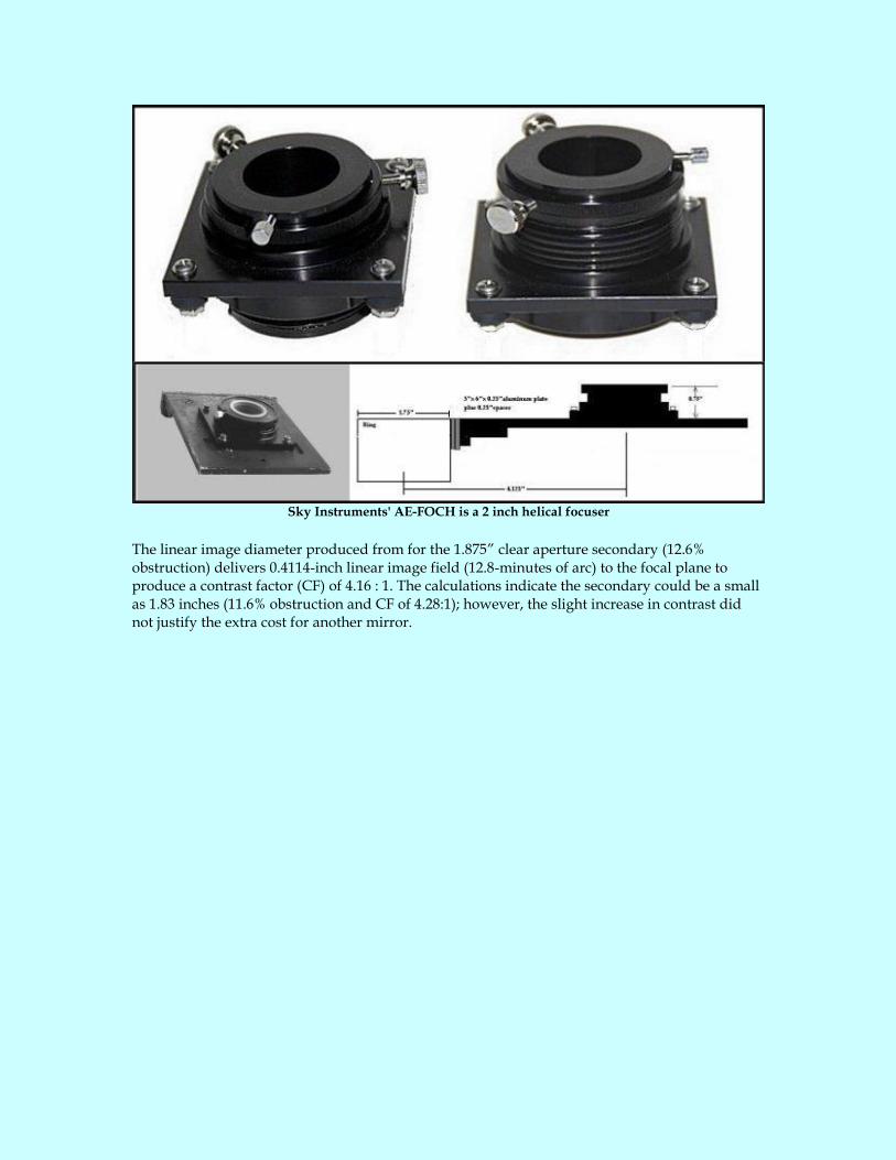
Sky Instruments' AE-FOCH is a 2 inch helical focuser
The linear image diameter produced from for the 1.875” clear aperture secondary (12.6% obstruction) delivers 0.4114-inch linear image field (12.8-minutes of arc) to the focal plane to produce a contrast factor (CF) of 4.16 : 1. The calculations indicate the secondary could be a small as 1.83 inches (11.6% obstruction and CF of 4.28:1); however, the slight increase in contrast did not justify the extra cost for another mirror.

TOP LEFT: the secondary section is a titanium jet engine ring, found in a local metal junkyard near the airport, and attaches to the trusses using 2-inch aluminum angles. TOP CENTER: The truss section is made up of eight one-inch aluminum O.D. tubes with 0.050-inch wall thickness. TOP RIGHT: The primary tube housing is an old discarded telescope tube rolled from 1/8th-inch aircraft quality aluminum. BOTTOM: Weight distribution/balance for the OTA and Saddle.
The 16” x 3” Pyrex primary mirror (produced by Dan Joyce) and 8-pound Novak primary cell is housed in the 23-lb, 18.25” x 33.5” rolled tube made from 1/8th-inch thickness aircraft quality aluminum that was welded inside and outside. The finished truss tube is 113.875 inches long. Had mirror coated at Spectrum Optical in Deltona, FL (http://www.spectrum-coatings.com/).
To assemble the truss tube a wooden lathe was constructed using a chain link fence post fitted into two plywood circles that were plugged into each end of the primary mirror tube assembly in order to center and balance all components. After construction the entire assembly was tightened and leveled to make sure all optical components would be centered within the telescope tube. The finished tube weighs 110.8 pounds with the optical components installed. If a closed in 18" x 112" x 0.125" aluminum tube it would weigh ~154 lbs. Open tube truss system designed to reduce weight by ~60%. The primary housing weighs 80.5 pounds, truss section weighs 15.2 lbs and saddle and weights weigh 71 pounds; so the OTA and saddle weigh 181.8 pounds.
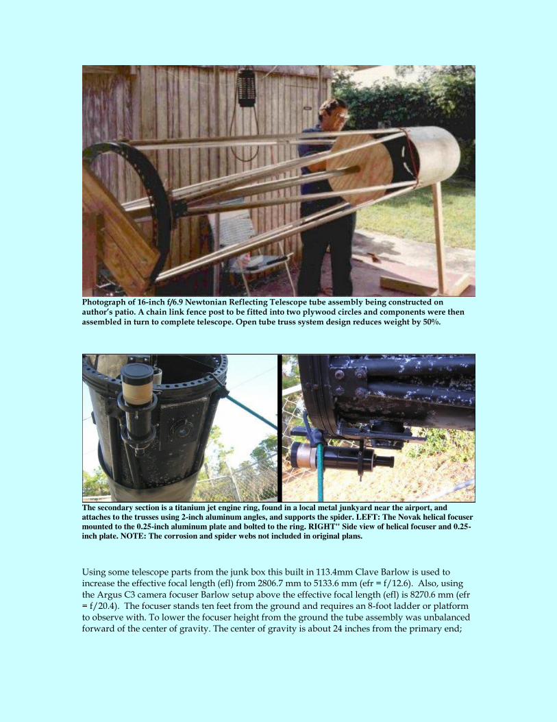
Photograph of 16-inch f/6.9 Newtonian Reflecting Telescope tube assembly being constructed on author’s patio. A chain link fence post to be fitted into two plywood circles and components were then assembled in turn to complete telescope. Open tube truss system design reduces weight by 50%.
The secondary section is a titanium jet engine ring, found in a local metal junkyard near the airport, and
attaches to the trusses using 2-inch aluminum angles, and supports the spider. LEFT: The Novak helical focuser
mounted to the 0.25-inch aluminum plate and bolted to the ring. RIGHT" Side view of helical focuser and 0.25-
inch plate. NOTE: The corrosion and spider webs not included in original plans.
Using some telescope parts from the junk box this built in 113.4mm Clave Barlow is used to increase the effective focal length (efl) from 2806.7 mm to 5133.6 mm (efr = f/12.6). Also, using the Argus C3 camera focuser Barlow setup above the effective focal length (efl) is 8270.6 mm (efr = f/20.4). The focuser stands ten feet from the ground and requires an 8-foot ladder or platform to observe with. To lower the focuser height from the ground the tube assembly was unbalanced forward of the center of gravity. The center of gravity is about 24 inches from the primary end;
so, to offset the imbalance 46 pounds of lead counterweight (14”x4”x2” bar) was added to the aft end of the 24" long saddle. The original saddle base plate was too long so it was replaced with a shorter 24” x 14” x 4”plywood structure, glued and bolted from end to end with 5/8th drill rod, steel end plates. The saddle cradles are made from a 24”x20”x0.5” aluminum tube from a junk yard that was cut and shapes then sandwiched between ¾-in plywood layers and with an edge support by a 2” wide by 1/8th inch aluminum strip. A 1”x1” round Teflon spacer is screwed to the saddle cradles that holds the primary tube in place and allows it to rotate when necessary.
THE MOUNT
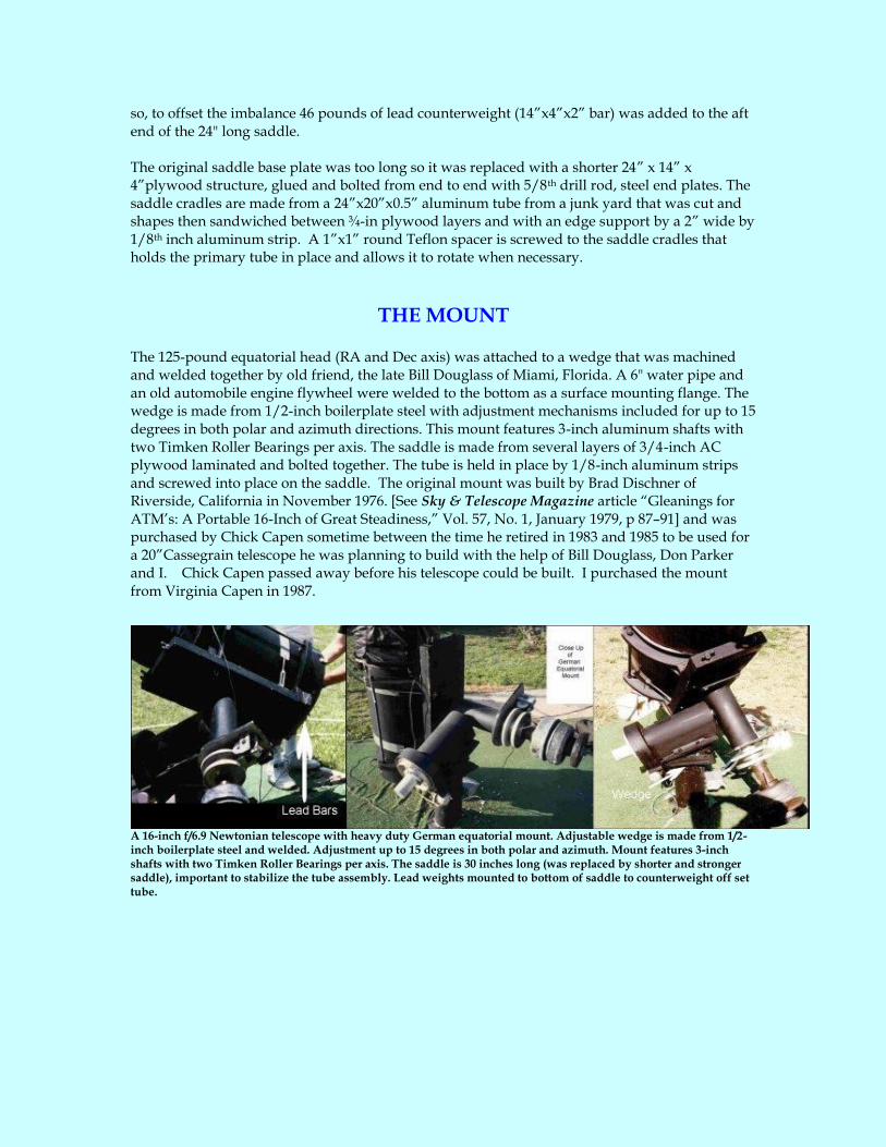
The 125-pound equatorial head (RA and Dec axis) was attached to a wedge that was machined and welded together by old friend, the late Bill Douglass of Miami, Florida. A 6" water pipe and an old automobile engine flywheel were welded to the bottom as a surface mounting flange. The wedge is made from 1/2-inch boilerplate steel with adjustment mechanisms included for up to 15 degrees in both polar and azimuth directions. This mount features 3-inch aluminum shafts with two Timken Roller Bearings per axis. The saddle is made from several layers of 3/4-inch AC plywood laminated and bolted together. The tube is held in place by 1/8-inch aluminum strips and screwed into place on the saddle. The original mount was built by Brad Dischner of Riverside, California in November 1976. [See Sky & Telescope Magazine article “Gleanings for ATM’s: A Portable 16-Inch of Great Steadiness,” Vol. 57, No. 1, January 1979, p 87–91] and was purchased by Chick Capen sometime between the time he retired in 1983 and 1985 to be used for a 20”Cassegrain telescope he was planning to build with the help of Bill Douglass, Don Parker and I. Chick Capen passed away before his telescope could be built. I purchased the mount from Virginia Capen in 1987.
A 16-inch f/6.9 Newtonian telescope with heavy duty German equatorial mount. Adjustable wedge is made from 1/2-inch boilerplate steel and welded. Adjustment up to 15 degrees in both polar and azimuth. Mount features 3-inch shafts with two Timken Roller Bearings per axis. The saddle is 30 inches long (was replaced by shorter and stronger saddle), important to stabilize the tube assembly. Lead weights mounted to bottom of saddle to counterweight off set tube.
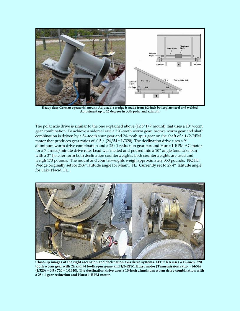
Heavy duty German equatorial mount. Adjustable wedge is made from 1/2-inch boilerplate steel and welded.
Adjustment up to 15 degrees in both polar and azimuth.
The polar axis drive is similar to the one explained above (12.5" f/7 mount) that uses a 10" worm gear combination. To achieve a sidereal rate a 320-tooth worm gear, bronze worm gear and shaft combination is driven by a 54-tooth spur gear and 24-tooth spur gear on the shaft of a 1/2-RPM motor that produces gear ratios of: 0.5 / (24/54 * 1/320). The declination drive uses a 9" aluminum worm drive combination and a 25 : 1 reduction gear box and Hurst 1-RPM AC motor for a 7-arcsec/minute drive rate. Lead was melted and poured into a 10” angle food cake pan with a 3” hole for form both declination counterweights. Both counterweights are used and weigh 173 pounds. The mount and counterweights weigh approximately 350 pounds. NOTE: Wedge originally set for 25.6º latitude angle for Miami, FL. Currently set to 27.4º latitude angle for Lake Placid, FL.
Close-up images of the right ascension and declination axis drive systems. LEFT: RA uses a 12-inch, 320 tooth worm gear with 24 and 54 tooth spur gears and 1/2-RPM Hurst motor [Transmission ratio: (24/54) (1/320) = 0.5 / 720 = 1/1440]. The declination drive uses a 10-inch aluminum worm drive combination with a 25 : 1 gear reduction and Hurst 1-RPM motor.
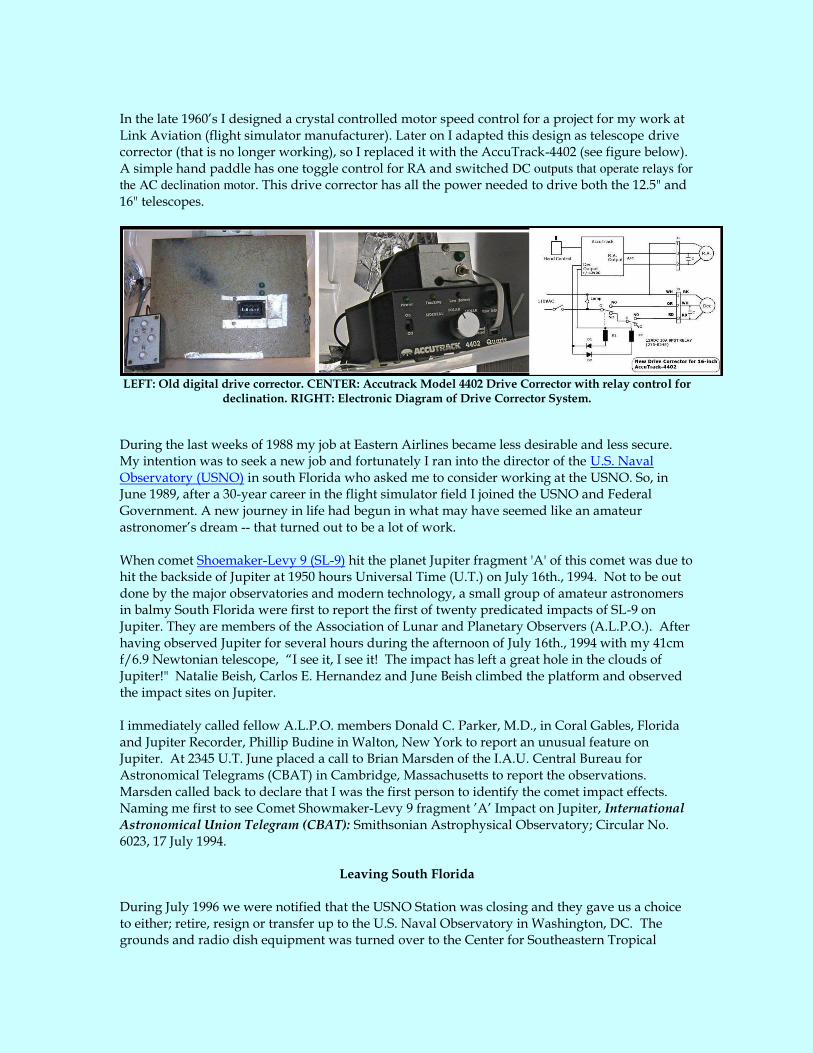
In the late 1960’s I designed a crystal controlled motor speed control for a project for my work at Link Aviation (flight simulator manufacturer). Later on I adapted this design as telescope drive corrector (that is no longer working), so I replaced it with the AccuTrack-4402 (see figure below). A simple hand paddle has one toggle control for RA and switched DC outputs that operate relays for
the AC declination motor. This drive corrector has all the power needed to drive both the 12.5" and 16" telescopes.
LEFT: Old digital drive corrector. CENTER: Accutrack Model 4402 Drive Corrector with relay control for
declination. RIGHT: Electronic Diagram of Drive Corrector System.
During the last weeks of 1988 my job at Eastern Airlines became less desirable and less secure. My intention was to seek a new job and fortunately I ran into the director of the U.S. Naval Observatory (USNO) in south Florida who asked me to consider working at the USNO. So, in June 1989, after a 30-year career in the flight simulator field I joined the USNO and Federal Government. A new journey in life had begun in what may have seemed like an amateur astronomer’s dream -- that turned out to be a lot of work. When comet Shoemaker-Levy 9 (SL-9) hit the planet Jupiter fragment 'A' of this comet was due to hit the backside of Jupiter at 1950 hours Universal Time (U.T.) on July 16th., 1994. Not to be out done by the major observatories and modern technology, a small group of amateur astronomers in balmy South Florida were first to report the first of twenty predicated impacts of SL-9 on Jupiter. They are members of the Association of Lunar and Planetary Observers (A.L.P.O.). After having observed Jupiter for several hours during the afternoon of July 16th., 1994 with my 41cm f/6.9 Newtonian telescope, “I see it, I see it! The impact has left a great hole in the clouds of Jupiter!" Natalie Beish, Carlos E. Hernandez and June Beish climbed the platform and observed the impact sites on Jupiter. I immediately called fellow A.L.P.O. members Donald C. Parker, M.D., in Coral Gables, Florida and Jupiter Recorder, Phillip Budine in Walton, New York to report an unusual feature on Jupiter. At 2345 U.T. June placed a call to Brian Marsden of the I.A.U. Central Bureau for Astronomical Telegrams (CBAT) in Cambridge, Massachusetts to report the observations. Marsden called back to declare that I was the first person to identify the comet impact effects. Naming me first to see Comet Showmaker-Levy 9 fragment ’A’ Impact on Jupiter, International Astronomical Union Telegram (CBAT): Smithsonian Astrophysical Observatory; Circular No. 6023, 17 July 1994.
Leaving South Florida During July 1996 we were notified that the USNO Station was closing and they gave us a choice to either; retire, resign or transfer up to the U.S. Naval Observatory in Washington, DC. The grounds and radio dish equipment was turned over to the Center for Southeastern Tropical

Advanced Remote Sensing (CSTARS) (http://www.cstars.miami.edu/). After living in the Miami area for over 24 years we finally left for the northeast. As of October 1996 I had only 4 years and 9 months away from retirement, so we moved south of Washington in Virginia and I reported to work at the U.S. Naval Observatory Time Service Engineering department on September 15, 1996.
During the years from August 1996 my participating in astronomical meetings became less frequent and numerous. However, continuing my astronomy interests I participated in observing programs at the observatory occasionally with our mathematician, Jim DeYoung, using the 12-inch, 26-inch Clark refractors and a 24-inch Cassegrain. Jim and I would observe Mars using these telescopes before and/or after duty hours; however, as an employee of the Federal Government I hesitated in sending my reports to ALPO and other amateur organizations for obvious reasons. So my observations of Mars during the 1996-97, 1998-99 and early 2000-01 apparitions are not published.
In January 1998 we drove down to Miami, Florida to visit friends and did some house hunting in Lake Placid. Dropped off the 16” mirror at Spectrum Optical in Deltona, FL and it was shipped to me in Dale City, VA later in the Spring of 1998. Sometime in 2001 I submitted retirement papers and began terminal leave on May 18, 2001 (Officially retried June 30, 2001) and moved back to Florida.

Back Home in Florida
Before retiring in mid-2001 my wife and I searched around central Florida for a secluded area away from the crowded city life. I was interested in finding a place where good "astronomical seeing" conditions for Solar System observing and a fairly dark sky that was good enough for deep sky object observing as well [see: Astronomical Seeing]. After several years of searching we found a quaint little town called Lake Placid, Florida that is located about eighty miles south of Orlando and 75 miles from either coast of Florida. It was with nervous trepidation that we selected a retirement home in central Florida.
Our home and observatory is located about 30 miles northwest of Lake Okeechobee in Lake Placid, Florida. We are a few miles northeast of this small farming and citrus growing town and a mile west of the 27,700 square-acre Lake Istokpoga (a mouth full to pronounce). Much of this region is covered with pine trees and by orange groves.
Photo-1: Typical view of the street we live on with only a few homes out here in the outback. Note: No street lights! Photo -2: Temporary telescope setup in south yard for observing Mars during 2001. Photo -3: Forest area from my driveway looking east toward Lake Istokpoga, approximately one mile away. (This is Federal Government land and will probably never be developed). The cloud at the horizon is a typical cumulus nimbus (thunderstorm) building up in the afternoon. Photo -4: South-side yard with 16” telescope in dog cage. Photo -5: North-side yard with 12.5” telescope
moved after observing cage installed. The prevailing winds in this region tend to be from the east over the big lake during most seasons. However, in winter the winds may be from the north and northwest over the central Florida landmass and becomes more turbulent. Lake breezes are common here and tend to cause temperature inversion layers over the coastal areas up to a few miles inland. These inversions stabilize the air from a few yards above the surface to around 1,500 to 2,000 feet altitude. Above this altitude the air may be variable and winds are usually either directly from the east or south east from the sea. Since this lake is a shallow 12 feet deep, the "lake effect" from the easterly winds over the warm water moderates the air above my home and provides a stable conditions to observe in. After observing for two years now it is clear that we made the right choice to move to this community. After a few years away from telescopic observing I returned to observing Mars in February 2012 and found the prevailing winds most often came from the southeast passing over Lake Okeechobee and Lake Istokpoga rendering the sky very stable.

MUSICAL TELESCOPES
A temporary site was selected to observe Mars during the 2001 apparition and the location worked out very well. The "seeing" here proved to be excellent and the sky is very dark. Since my smaller telescope was easier to set up a home-built 12.5-inch f/7 Newtonian was assembled in the north side yard and used to observe Mars during the Great 2001 Dust Storm! The pier was found to be too close to the house and rendered Mars hidden from view during the 2001 and 2003 apparitions. I began construction on a new observing site on the north side of our house in Lake Placid, Florida. A concrete base was poured with the help of my friend Don Parker, who drove up from Miami to stay with us over that weekend and we finished the project on August 24, 2002. However, the telescope was found to be too close to the house and rendered Mars hidden from view during part of the 2003 apparition. After clearing away some overhanging trees this site has been rendered excellent for observing deep sky objects with the 12.5-inch telescope, so sometime in the future it will be mounted permanently.
A true friend, Don Parker, mixing concrete and ready to fill the hole in the August heat of Florida!
A hole dug in sand 4-feet deep Bottom is 3.5 x 3.5-feet square and top is 2 x 2-feet square (truncated pyramid). Frame in place is ¾"x24"x18" CDX plywood. CENTER: Rebar (steel reinforcing rods) welded into box frame to be used installed in hole and frame. RIGHT: Hole now is framed with Rebar cage in place and ready for pouring concrete.
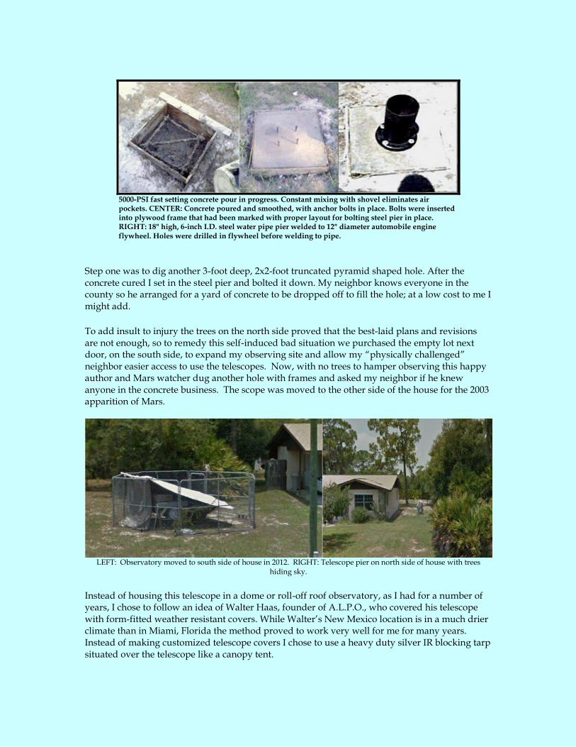
5000-PSI fast setting concrete pour in progress. Constant mixing with shovel eliminates air pockets. CENTER: Concrete poured and smoothed, with anchor bolts in place. Bolts were inserted into plywood frame that had been marked with proper layout for bolting steel pier in place. RIGHT: 18" high, 6-inch I.D. steel water pipe pier welded to 12" diameter automobile engine flywheel. Holes were drilled in flywheel before welding to pipe.
Step one was to dig another 3-foot deep, 2x2-foot truncated pyramid shaped hole. After the concrete cured I set in the steel pier and bolted it down. My neighbor knows everyone in the county so he arranged for a yard of concrete to be dropped off to fill the hole; at a low cost to me I might add.
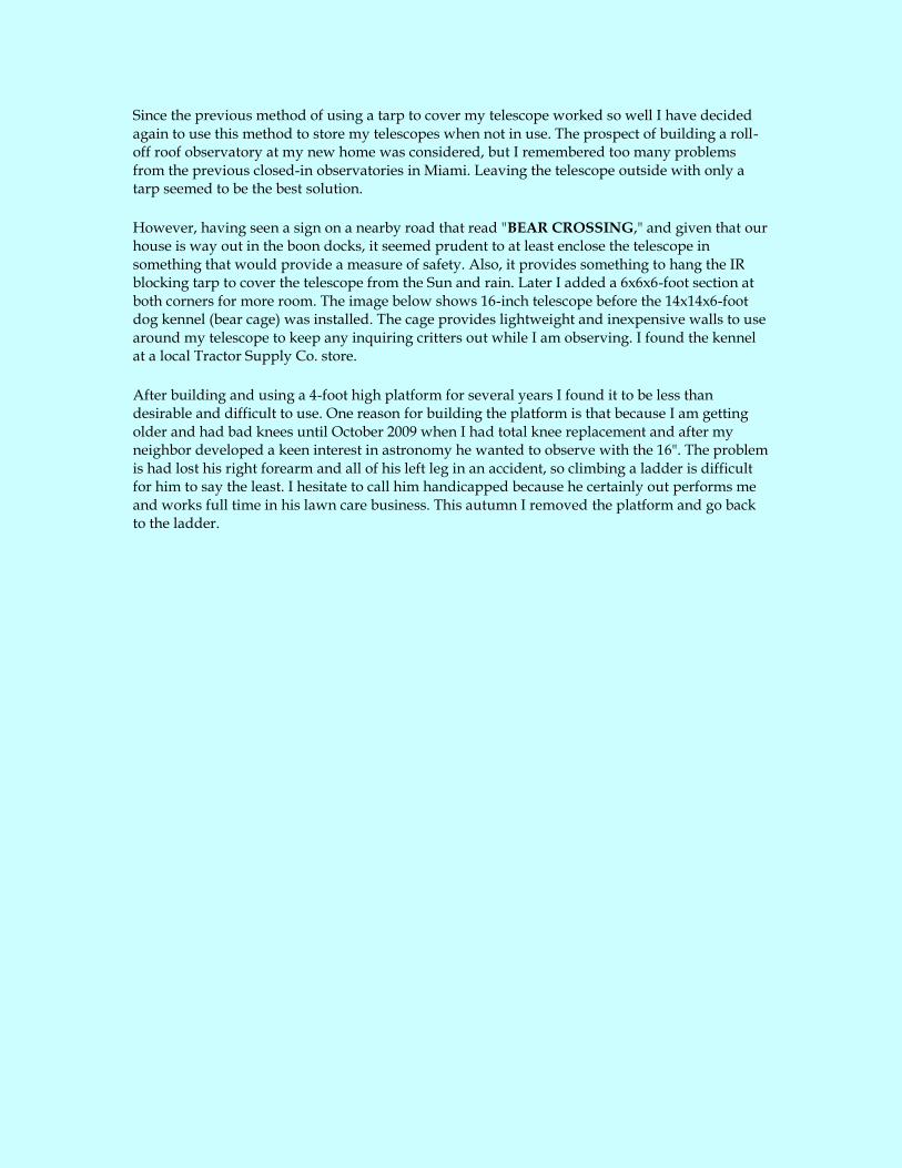
To add insult to injury the trees on the north side proved that the best-laid plans and revisions are not enough, so to remedy this self-induced bad situation we purchased the empty lot next door, on the south side, to expand my observing site and allow my “physically challenged” neighbor easier access to use the telescopes. Now, with no trees to hamper observing this happy author and Mars watcher dug another hole with frames and asked my neighbor if he knew anyone in the concrete business. The scope was moved to the other side of the house for the 2003 apparition of Mars.
LEFT: Observatory moved to south side of house in 2012. RIGHT: Telescope pier on north side of house with trees
hiding sky.
Instead of housing this telescope in a dome or roll-off roof observatory, as I had for a number of years, I chose to follow an idea of Walter Haas, founder of A.L.P.O., who covered his telescope with form-fitted weather resistant covers. While Walter’s New Mexico location is in a much drier climate than in Miami, Florida the method proved to work very well for me for many years. Instead of making customized telescope covers I chose to use a heavy duty silver IR blocking tarp situated over the telescope like a canopy tent.
Since the previous method of using a tarp to cover my telescope worked so well I have decided again to use this method to store my telescopes when not in use. The prospect of building a roll-off roof observatory at my new home was considered, but I remembered too many problems from the previous closed-in observatories in Miami. Leaving the telescope outside with only a tarp seemed to be the best solution.
However, having seen a sign on a nearby road that read "BEAR CROSSING," and given that our house is way out in the boon docks, it seemed prudent to at least enclose the telescope in something that would provide a measure of safety. Also, it provides something to hang the IR blocking tarp to cover the telescope from the Sun and rain. Later I added a 6x6x6-foot section at both corners for more room. The image below shows 16-inch telescope before the 14x14x6-foot dog kennel (bear cage) was installed. The cage provides lightweight and inexpensive walls to use around my telescope to keep any inquiring critters out while I am observing. I found the kennel at a local Tractor Supply Co. store.
After building and using a 4-foot high platform for several years I found it to be less than desirable and difficult to use. One reason for building the platform is that because I am getting older and had bad knees until October 2009 when I had total knee replacement and after my neighbor developed a keen interest in astronomy he wanted to observe with the 16". The problem is had lost his right forearm and all of his left leg in an accident, so climbing a ladder is difficult for him to say the least. I hesitate to call him handicapped because he certainly out performs me and works full time in his lawn care business. This autumn I removed the platform and go back to the ladder.
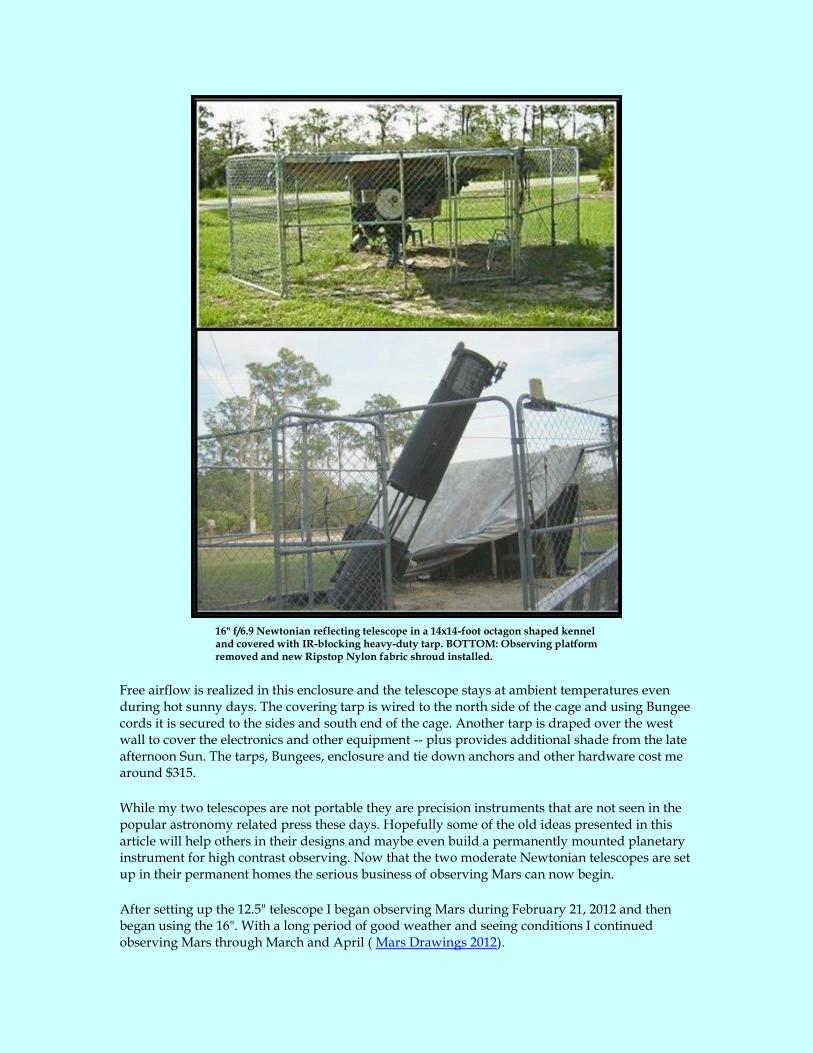
16" f/6.9 Newtonian reflecting telescope in a 14x14-foot octagon shaped kennel and covered with IR-blocking heavy-duty tarp. BOTTOM: Observing platform removed and new Ripstop Nylon fabric shroud installed.
Free airflow is realized in this enclosure and the telescope stays at ambient temperatures even during hot sunny days. The covering tarp is wired to the north side of the cage and using Bungee cords it is secured to the sides and south end of the cage. Another tarp is draped over the west wall to cover the electronics and other equipment -- plus provides additional shade from the late afternoon Sun. The tarps, Bungees, enclosure and tie down anchors and other hardware cost me around $315.
While my two telescopes are not portable they are precision instruments that are not seen in the popular astronomy related press these days. Hopefully some of the old ideas presented in this article will help others in their designs and maybe even build a permanently mounted planetary instrument for high contrast observing. Now that the two moderate Newtonian telescopes are set up in their permanent homes the serious business of observing Mars can now begin.
After setting up the 12.5" telescope I began observing Mars during February 21, 2012 and then began using the 16". With a long period of good weather and seeing conditions I continued observing Mars through March and April ( Mars Drawings 2012).

LEFT: Telescope Farm Growing. RIGHT: 12.5" with Baader solar filter.
Air pollution is on the increase and will very well decrease our seeing conditions in the future, but does not seem to be a big problem here yet. Although we do see numerous clouds they are usually the "fair weather" cumulus type and have little effect on seeing. The closest highway to my property is about 5 miles away so a cloud of auto exhaust does not drift over this far.
All said and done, this telescope works great and holds collimation perfectly. It even survived hurricane Andrew and was in prefect optical alignment when remounted. I had a lot of help from friends around the ATM world. Well, of course it wasn’t out in the storm -- just lying on the living room floor in 3 inches of water! Enough said about storms!
NOTE: Many of the parts used to build the telescopes described in this article were available from Kenneth F. Novak & Co. Unfortunately, Kenneth passed away some years back and his company is not longer in business. Too bad, his superb and inexpensive telescope parts were widely used in the ATM world.
Now that video is available using the webcam and laptop PC my neighbor and I can now sit on the ground under a mosquito net and observe planets without standing for long periods of time or climbing ladders. Technology makes it possible for anyone to enjoy observing without a lot of effort. A useful item I have found to be the best method for avoiding mosquito bites is the “No-See-Um Bug Jacket” from Campmor (http://www.campmor.com/Product___82170).
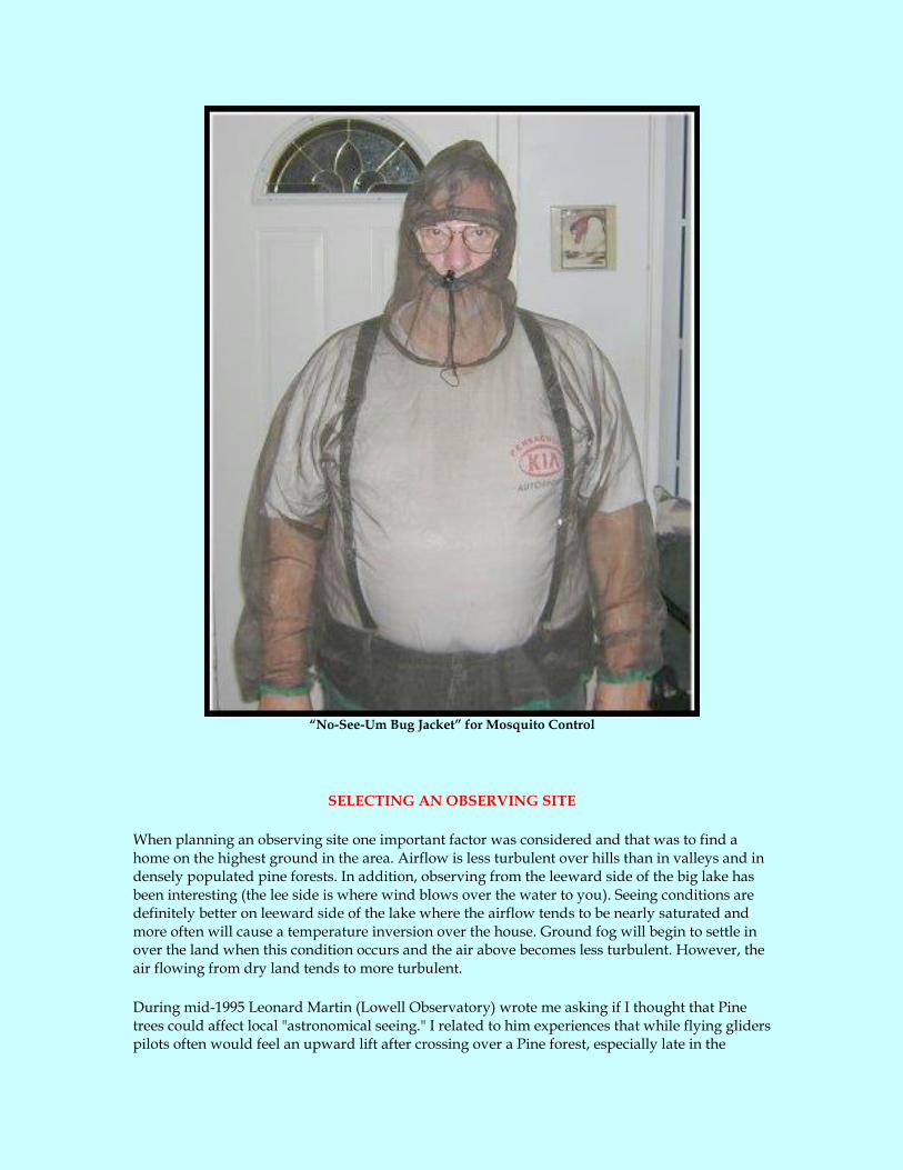
“No-See-Um Bug Jacket” for Mosquito Control
SELECTING AN OBSERVING SITE
When planning an observing site one important factor was considered and that was to find a home on the highest ground in the area. Airflow is less turbulent over hills than in valleys and in densely populated pine forests. In addition, observing from the leeward side of the big lake has been interesting (the lee side is where wind blows over the water to you). Seeing conditions are definitely better on leeward side of the lake where the airflow tends to be nearly saturated and more often will cause a temperature inversion over the house. Ground fog will begin to settle in over the land when this condition occurs and the air above becomes less turbulent. However, the air flowing from dry land tends to more turbulent.
During mid-1995 Leonard Martin (Lowell Observatory) wrote me asking if I thought that Pine trees could affect local "astronomical seeing." I related to him experiences that while flying gliders pilots often would feel an upward lift after crossing over a Pine forest, especially late in the

afternoon or early evening. Glider pilots are always looking for "thermals," as we call them, to provide lift to increase altitude. Leonard wrote that he understood and attributed the bad seeing he would experience after pointing the telescope over the Pine trees next to the dome. He told me that he had been "campaigning against trees for some time" and that he wanted to have the tall pine trees adjacent to the 24" dome cut down; but local environmentalists and animal rights groups would not allow Lowell to do it. So, users of the big refractor would just have to put up with the problem.
Years ago I would setup my telescope in a camping ground in the Everglades where the typical camp sites would be located in a clearing no larger than 30 or 40 feet across and was surrounded by Pine trees. Using binoculars and a telescope I could see the turbulent waves rising from the trees against the glow of light pollution from Miami and Homestead. The effect from the turbulence on stars was obvious and spoiled the "seeing" above the trees.
Trees radiate heat and emit vapors at nightfall, therefore spoiling the air immediately above them. Pine trees are among the worst offenders and I try to avoid setting up a telescope in a densely populated pine forest. The main force that disrupts the air above the forest comes from vertical air circulation within the trees that is conducted up through the tree trunks and from the thick layer of the dead pine needles (biomoss) under them. This biomoss also releases heat plumes, therefore adds to the turbulence. The only saving grace is if you set up your telescope upwind from the trees.
While this area is populated with tall Florida pine trees they are not densely packed so as to cause air turbulence. Much of the ground is covered with pine cones and needles; however, the biomoss is only a few inches deep here compared with a much thicker layer in dense forests. Most of the land area here is covered by orange groves and the millions of orange trees have little effect on the air quality. During evenings in the late summer months thunderstorms increase in number and severity here in south central Florida, so one must be patient and know when and when not to haul the telescope out. While the landscape is fairy flat so the observer has no problem seeing those high cumulonimbus (anvil shaped thunderstorm clouds) coming. By late autumn the sky beings to be less cloudy and fewer thunderstorms will occur.
The activity of the local surface boundary layer is quite interesting to record around my home in Lake Placid. Since moving here records of the outside air temperature (OAT) changes have been made from around 4 a.m. until 9 a.m. There is a definite cycle that occurs an hour before Sunrise when the OAT decreases a few degrees. It remains steady for a few hours then gradually increases until around mid-morning and then begins to increase more rapidly. A ground fog develops after the OAT decreases and the fog rolls over my home that is located on a 21-meter ridge and westward down a slight incline to a shallow valley. This valley is several miles wide and then meets another ridge a few miles away.
When living in Dade Country, Florida, we would experience turbulent seeing conditions during wintertime when cold fronts would roll in from the northwest. Surprisingly the seeing would be very good right before the front, but would decrease to nearly zero for at least 48 hours afterward. This is because the upper wind and clouds cross the Miami area from the northwest and the lower air masses flow in a perpendicular direction or from 45 to 90 degrees from the upper winds. The mixing of the two air systems then causes turbulence at the point where the two air masses meet.
In central Florida these conditions are less severe when cold fronts pass over us so seeing doesn’t seem to be effected as much. This may be because Lake Placid is located almost centered of the
state where it is widest and the large number of lakes in the region moderate the lower air lasses more so that it does further south of here. Also, when cold fronts pass the higher clouds can be seen to moved from the southwest across the state to the northeast; however, unlike the winds of southeast Florida, the lower wind and cloud systems cross in the exact opposite direction in central part of the state.
[Addendum: See: NOAA El Niño Page and Climate Prediction Center]
The weather in Florida apparently is affected by the two ocean-atmosphere systems in the tropical Pacific called El Niño and La Niña. El Niño apparently began to strengthen during mid-2004 and weakened in early 2005. After El Niño weakened in early 2005 there was a period of “normal” ocean temperatures in the equatorial Pacific then La Niña was noticed in mid-2007. By the end of May 2008 La Niña began to weaken and the Pacific Ocean returned to “normal” and remained so until the summer of 2009 when El Nino began to develop and continued through May 2010. La Nina then began shortly thereafter in July 2010 and continues through March 2011.
It seems like these two conditions affect our weather here in Florida and after a fairly long drought beginning after the 2004-2005 El Niño and the 2007 La Niña periods ended, the drought seemed to be gradually ending with the onslaught of summer thunderstorms in 2008. However, “mother nature” threw us a curve ball and the drought continued until May 2009 when the rains returned in full fury. The winter of 2009-2010 started off with average temperatures lower than “normal” then turned unseasonably colder than normal in January 2010 and with above average rain fall and continued through February 2010. Weather conditions appeared "normal" during March though November 2010, then it turned cold again in December then we had a 9-day period of cold mornings when temperatures fell to 32 degrees and below
South Florida observers have long noted that “astronomical seeing” appears to vary from very good to not so good and some equate this to the El Niño/La Niña cycles. Current thinking is that “seeing’ improves after an El Niño/La Niña period has ended. Often during El Nino cycles the southern jet stream will move southward over central and south Florida causing our “seeing” to be less than desirable [see: Astronomical Seeing].
SUMMARY
For most of our lives we have little choice in selecting an observing site. We must provide for our family and go where the jobs are, find available housing, shopping, transportation, etc., and this usually means living in large metropolitan areas. Even if our choices are limited we can usually make our home a better place to observe from by following a few rules in studying micrometeorology. This deals with the atmosphere a few yards above the ground. A study of our neighborhood is important in determining what obstructions are close by that will cause turbulence about our telescopes.
In the past several experienced planetary observers complained to me about their bad seeing at their home. While at the time I had not reason to doubt them it occurred to me to ask where their telescope was setup for observing. Inevitably they would tell me that their telescope had to be rolled out of a garage onto an asphalt driveway where they would observe. This is probably the worst surface to setup a telescope on because after dark, when it begins to cool off, plumes of warmer air will boil up for the surface spoiling telescopic viewing. When they followed my advice; to just move off the blacktop and into the grass, their complaining of bad seeing went away.

So, much of what I have written here is about a person who retires and has more control over where they live. However, much of this article will guide you to a better understanding of the conditions you will need to improve you situation even if you cannot be blessed with the sky in which I live under.
I have found the conditions for telescopic observing here in central Florida, around Highlands County, first rate year round. During the 2001, 2003 and 2005 apparitions of Mars I began to observe the planet nearly every afternoon and evening. On average the seeing ranged from 5 to 7 during less than excellent conditions and 8 to 10 during most of the observing sessions (using the ALPO Mars Section seeing scale from 0 to 10, where 0 is the worst and 10 is perfect).
The sky at night is generally very dark and the visible stars on clear nights can range from magnitudes from 6.5 to 7.5, depending on the relative humidity of course. The humidity usually runs 50% during spring to 45% to 75% in summer and 45% to 50% in autumn and as low as 30% during the winter. Temperatures can be high during July and August and range from 80 to 100 during the mid-afternoon; however, during 2002 the cloudy/rainy season has been much cooler. The temperature has ranged from 71º F in the early morning to around 85º F during late afternoon. From mid-October through mid-May temperatures may range from 35º F on cold nights to the lower 60’s at night and 75º during the day. Again we experienced an unusual cold weather period during November 2009 and again in January 2010 and December 2010 when temperatures fell below 32 degrees for weeks at a time.
With the many lakes in the area the weather is moderate and is less tropical than Southeast Florida or closer to the coasts. The topography in the area where I live is well suited for astronomical observing and the easterly breezes from large lakes form a stable atmosphere for excellent "astronomical seeing." The rolling hills and ridges that run north and south through the center of Florida provide much area for building higher elevation observing sites. The sparsely populated forest of pine trees and large orange groves in the region has little effect on the atmosphere.
After living in south Florida for nearly 20 years before a hurricane actually hit us we survived the category-5 hurricane Andrew on August 24, 1992 and were fortunate to live there for several more years without another storm. After moving north to central Florida we had hoped to never see another large hurricane again, but that was not to be. In 2004 we saw hurricanes Charley, Frances and Jeanne, then in 2005 hurricane Wilma! While these storms were not as strong as Andrew the memories of that hurricane left us nervous. Then in September 2017 we had hurricane “Irma” that damaged many homes in our area, including minor damages to our home.
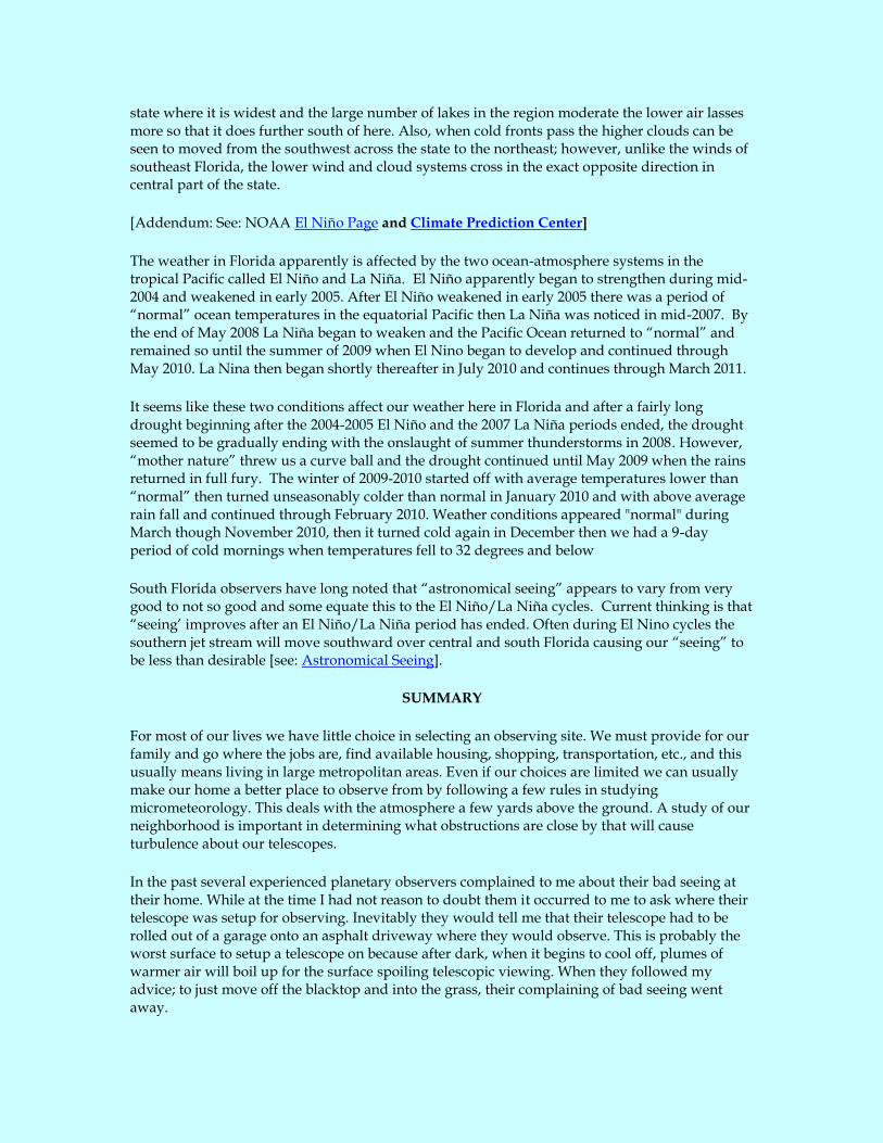
LIGHT POLLUTION: In an effort to curb light pollution the Astronomical Society of Highlands County, Florida several local amateur astronomers of the Palm Beaches (headed by Kye Ewing) and the Highlands County Audubon Society waged a campaign to enlist the help from the Highlands County Commission to reduce light pollution in our area. Area newspapers published articles [BALDRIDGE, KONKOLY and TUFFLEY, 2009] in support of the group and from my perspective our effort appeared to pay off with a decrease in apparent sky glow in my western sky. To support this theory see the image below ripped from Google Earth with the light pollution overlay from 2007, 2011 and then 2018.
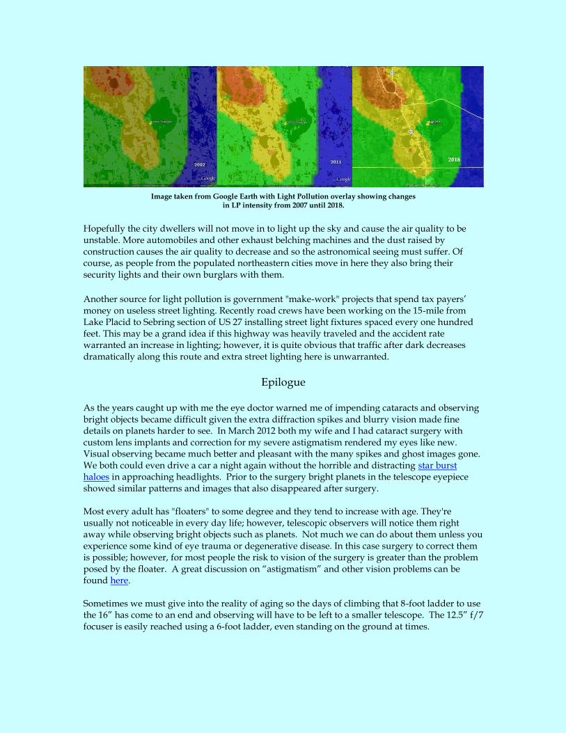
Image taken from Google Earth with Light Pollution overlay showing changes in LP intensity from 2007 until 2018.
Hopefully the city dwellers will not move in to light up the sky and cause the air quality to be unstable. More automobiles and other exhaust belching machines and the dust raised by construction causes the air quality to decrease and so the astronomical seeing must suffer. Of course, as people from the populated northeastern cities move in here they also bring their security lights and their own burglars with them.
Another source for light pollution is government "make-work" projects that spend tax payers’ money on useless street lighting. Recently road crews have been working on the 15-mile from Lake Placid to Sebring section of US 27 installing street light fixtures spaced every one hundred feet. This may be a grand idea if this highway was heavily traveled and the accident rate warranted an increase in lighting; however, it is quite obvious that traffic after dark decreases dramatically along this route and extra street lighting here is unwarranted.
Epilogue
As the years caught up with me the eye doctor warned me of impending cataracts and observing bright objects became difficult given the extra diffraction spikes and blurry vision made fine details on planets harder to see. In March 2012 both my wife and I had cataract surgery with custom lens implants and correction for my severe astigmatism rendered my eyes like new. Visual observing became much better and pleasant with the many spikes and ghost images gone. We both could even drive a car a night again without the horrible and distracting star burst haloes in approaching headlights. Prior to the surgery bright planets in the telescope eyepiece showed similar patterns and images that also disappeared after surgery. Most every adult has "floaters" to some degree and they tend to increase with age. They're usually not noticeable in every day life; however, telescopic observers will notice them right away while observing bright objects such as planets. Not much we can do about them unless you experience some kind of eye trauma or degenerative disease. In this case surgery to correct them is possible; however, for most people the risk to vision of the surgery is greater than the problem posed by the floater. A great discussion on “astigmatism” and other vision problems can be found here. Sometimes we must give into the reality of aging so the days of climbing that 8-foot ladder to use the 16” has come to an end and observing will have to be left to a smaller telescope. The 12.5” f/7 focuser is easily reached using a 6-foot ladder, even standing on the ground at times.
Time marches on and as we grow older it is inevitable that a time will come when systematic observing will end and we must either scale down our telescope time or just quit observing all together. Climbing the 8-foot ladder to reach the eyepiece of my 16” f/6.9 Newtonian telescope has become more difficult and it is time to dissemble it and store it away. The dissembled tube assembly can be temporarily stored on my back patio; however, the heavy duty mount for the 16” telescope as well as the heavy Parks mount used for the 12.5” f/7 Newtonian must remain in place until a suitable storage shed can be made available. It is time to scale down my telescope time to casual observing with my 6” f/4 telescope. On March 25, 2017 I started to dissemble the 16” f/6.9 Newtonian to temporarily store it on the patio. The mount needed some rust removable and painting, so after that I then installed the saddle from the Parks mount to use with the 12.5” f/7 Newtonian. This scope is shorter and easier to use.
16” f/6.9 Newtonian dissembled.
Given that most amateur astronomers have opted to purchase or build light weight, portable large aperture telescopes it is inevitable that interest in my equipment has fallen by the wayside so they may very well remain in storage or donated to some organization that can use them. All good things must come to an end. The cage is gone as of March 01, 2018 when a young couple from Okeechobee drove up and picked it up. Little by little the Lake Istokpoga Observatory is disappearing.

Any suggestions or comments please e-mail me at CONTACT ME.
CURRICULUM VITAE
Reference
Beish, J.D, (2008); Astronomical Seeing, Mars Observers Café, Internet Web Page index.html
Beish, J.D, (2008). Practical Calculations for the Newtonian Secondary Mirror , Mars Observers Café, Internet Web Page. ED BALDRIDGE, (2009), “County to consider lighting ordinance,” The News Sun, March 12, 2009
JIM KONKOLY, (2009), “County Commissioners Looking Into Regulating Lighting,” Highlands Today, March 11, 2009:
CHRISTOPHER TUFFLEY, (2009), “Let there be dark,” The News Sun, Friday, July 03, 2009
Saxon, Capt. Vernon P. (1975), “An Electronic Speed Control for Clock Drives,” S&T, January.