labour-based methods and technologies for … · technologies for employment-intensive construction...
TRANSCRIPT

Labour-based methods andtechnologies for employment-intensive construction works
A cidb guide to best practice
Best Practice Guideline – Part 4-7
Water-bound Macadam

Confronting joblessness
This set of best practice guidelines for labour-based construction represents a significantinvestment of leadership by the South AfricanConstruction Industry “to spearhead jobcreation and skills development so that ourgrowing economy is increasingly accessible toall citizens”
(Minister Stella Sigcau, SA ConstructionIndustry – Status Report 2004).
In finalising this set as a tool for designers andpractitioners, the Construction IndustryDevelopment Board (cidb) has assembled theknowledge and experience given freely byindustry through a consultative process thatcommenced in 1996.
Taking forward this process, the cidb haspublished these guidelines in fulfilment of itsmandate to “establish and promote bestpractice… and the improved performanceof… participants in the construction deliveryprocess”.
“We have made the firm commitment toconfront the challenges of poverty andjoblessness. We have made the solemnpledge that we will do everythingpossible to achieve the goal of a betterlife for all our people.”
President Thabo Mbeki, 18 May 2004 – launch of the Expanded Public Works
Programme.
Labour-based methods and technologies foremployment-intensive construction works
In this set: (colour coded)
Part 1An overview of labour-based technologies andmethods in employment-intensive works
Part 2Labour-based construction methods2.1 Labour-based construction methods for
earthworks
Part 3Labour-based methods for materialsmanufacture3.1 Precast concrete products, bricks and block
making3.2 The BESA building system
Part 4Labour-based construction technologies4.1 Labour-based open channel flow
technology4.2 Rubble masonry dam construction
technology4.3 Rubble masonry concrete arch bridge
construction technology4.4 Foamed bitumen gravel4.5 Cast in situ block pavement4.6 Emulsion-treated gravel4.7 Water-bound Macadam4.8 Slurrybound and composite Macadam
construction4.9 Labour-based construction methods for
unsealed roads
These best practice guidelines are supported bythe Expanded Public Works Programme (EPWP),which directs a significant and increasing pro-portion of South Africa’s public investmenttowards a labour-intensive programme ofconstruction, drawing the unemployed intoproductive work and providing access to skillsdevelopment.
The guidelines draw on international experienceand are endorsed by Engineers Against Poverty(EAP), an international development NGO esta-blished by leading UK engineering institutions.EAP is working to ensure that the engineeringindustry remains at the forefront of efforts toreduce and eventually eliminate global poverty.

Overview of best practice labour-based guidelines 2
1. Introduction 3
2. Materials and specifications 6
3. Practical aspects 9
4. Structural design 13
5. Plant and equipment 13
6. Construction 14
7. Quality control 19
8. Specialist literature 20
Acknowledgements 25
cidb is a public entity established in terms of the CIDBAct, 2000 to provide strategic direction for sustainablegrowth, reform and improvement of the constructionsector and its enhanced role in the country’s economy.In pursuit of this aim cidb partners with stakeholdersand regulates the construction industry around acommon development agenda underpinned by bestpractice procurement and project processes.
Construction Industry Development BoardPrivate Bag X14, Brooklyn Square, 0075 Tel: 27 12-481 9030 Fax: 27 12-343 7153 E-mail: [email protected] Website www.cidb.org.za
ISBN: 0-621-35565-8 Printed March, 2005
Labour-based methods and technologies for employment-intensive construction works
A cidb guide to best practice
Best Practice Guideline – Part 4-7
Water-bound MacadamEdition
of CIDB document1032March 2005
ST1
Contents

Part 4 – Labour-based construction technologies
The South African White Paper Creating an Enabling Environment forReconstruction, Growth and Development in the Construction Industry(1999) expresses a vision for public-sector delivery aimed at optimising
employment opportunities through labour-intensive construction. This can berealised in the delivery of infrastructure through the adoption, where technicallyand economically feasible, of:• labour-based methods of construction and manufacture where labour,
utilising hand tools and light equipment, is preferred to the use of heavyequipment for specific activities; and
• labour-based technologies where there is a shift in balance between labourand equipment in the way the work is specified and executed for selectedworks components.
Appropriate specifications and labour-based technologies are required tooptimise employment opportunities generated per unit of expenditure. Theabsence of adequate design information on labour-based technologiesfrequently limits the choices available in project design. As a result labour-basedtechnologies are often approached circumspectly and conservatively.
These best practice guidelines present current state-of-the-art practices in a widerange of labour-based construction methods, manufacturing methods andtechnologies which have been successfully utilised in South Africa in recent years.They are intended to provide sufficient technical information on such methodsand technologies to enable those responsible for the design of projects to makeconfident and informed choices on their use in projects.
The cidb best practice guidelines establish desirable and appropriate standards,processes, procedures and methods relating to the implementation ofemployment-intensive works using:• labour-based construction methods for earthworks;• labour-based methods for materials manufacture; and• labour-based construction technologies.
Following a process of peer review and public comment cidb has published theguidelines in Government Gazette No 27352 on 11 March 2005.
The guidelines can be downloaded from the cidb website www.cidb.org.za freeof charge and can be obtained in hard-copy from cidb or the South AfricanInstitution of Civil Engineering (SAICE), website www.civils.org.za, at the cost ofprinting and postage.
Overview of the best practice labour-based guidelines

1.1 Background
Macadam-type pavement layers have been used successfully in South Africa formany decades. Macadam-type pavement layers traditionally refer to a layer ofalmost single-sized stone (usually 53mm nominal size for recent projects) in whichthe voids are filled with a dry, cohesionless fine aggregate filler. With the growingneed for superior performance, a variety of modifications have been introduced,which include filling the voids with bitumen, slurry, etc.
A macadam layer essentially consists of a stone skeleton of which the voids arefilled with another material. The stone skeleton, because of its single size, haslarge amounts of voids but has a high shear strength. If confined properly, acrucial requirement for macadam base courses, the stone skeleton forms the‘backbone’ of the macadam and is largely responsible for the strength of theconstructed layer. The material used to fill the voids provides lateral stability tothe stone skeleton but adds little bearing capacity. This structure also gives water-bound macadam its good resistance to water as it drains well and the stoneskeleton is less susceptible to the water present in the layer.
A water-bound macadam (WM) refers to a method of construction wherebywater is used to force fine material into the voids during compaction. Withproper construction control, and a phased construction procedure, the water-bound macadam offers a suitable labour intensive method for road construction.
1.2 Origins of macadam construction (Hefer, 1997)
The origins of macadam-type pavement construction can be traced back to aperiod between 1750 and 1830 during which two Scottish engineers, ThomasTelford and John Louden McAdam were active in developing and promoting theirrespective road-building techniques in England. Telford used fairly large stones(75 mm long, 125 mm wide and 325 mm high) to build a foundation layer on alevel roadbed. The heights of these large stones decreased from the centre-lineto the edge of the roadway to create a slight camber. Smaller stones were driveninto the open voids on the surface of this layer and any projecting points werebroken off. A 100 – 200 mm thick layer of small broken stone was then placed ontop of the foundation layer. McAdam simply used layers of broken stones, noneof whose dimensions exceeded 25 mm and these layers were placed directly onthe roadbed. The broken stone was angular andconsolidated under traffic. McAdam recommendedthat the road be raised above the surroundingground to improve drainage. A layer of smallbroken stones, spread on the surface of the road,was used by both road-builders. These stones werebroken down further and compacted by traffic toproduce a solid, smooth riding surface. Figure 1illustrates the difference between the approachesused by Telford and McAdam.
Neither Telford nor McAdam used any fine filler inthe voids of the stone layer and it is not clear whenthis practice originated. Macadam construction wasboosted by the invention of the stone crusher andsteamroller in the 1860s but, in essence, the processremained labour-intensive.
Increased motorised-vehicle traffic at the turn of the century created dust andsurface disintegration problems because of higher vehicle speeds and increased
3labour-based methods and technologies
1. Introduction
Part 4-7 – Waterbound macadam
This document is mainly compiled from:Guidelines for the Selection, Design andConstruction of Water-bound MacadamBase Layers, Guideline Document DP-2000/5, published by Transportek CSIR.The development of this guideline docu-ment was sponsored by the GautengDepartment of Transport and PublicWorks, Directorate Design and theSouth African National Road AgencyLimited.
Note
Figure 1: Telford and McAdam pavements

friction between tyre and pavement. This led to the development of tarpenetration macadams.
1.3 The history of macadam pavements in South Africa
Macadam pavement construction went through various phases in South Africa.Several provincial road authorities and major municipalities constructedmacadam pavements until the 1960s and even as late as the 1970s. Thereafter theuse of water-bound macadam declined in favour of materials which were moreeasily placed by machine.
However, the use of water-bound macadam did notonly decline in South Africa, but did so all over theworld. In the developed world where wagesincreased dramatically, the use of water-boundmacadam has practically disappeared. But even inother developing countries, the mechanisationtrend has also lead to much reduced use of thistechnique.
The good in-service record of macadam pavementsin the former Transvaal (Burrow, 1975) and in thewet climate of Natal caused the interest in this typeof construction to be retained and gave rise toseveral attempts during the 1980s to mechanise theconstruction of macadam layers. These attemptsvaried from using motorised graders to spread andlevel the coarse aggregate and sand spreaders andmechanical brooms to spread and cause the fine
aggregate filler to penetrate (Horak, 1983), to laying the coarse aggregate withmodified pavers (Roux and Otte, 1993, McCall et al, 1990).
A new generation of macadam-type materials evolved in South Africa during thelate 1980s and 1990s. The process started with the development of partiallypenetrated macadams (Roux and Otte, 1993) in Natal. The need for job creationand empowerment through labour-intensive road construction projects andcontractor development led to the development of slurry-bound and compositemacadams that were used on several pilot projects by the Greater JohannesburgMetropolitan Council (Horak et al, 1995). A distinction is therefore made betweenthe macadam material types outlined in 1.4 and 1.5.
1.4 Conventional types of macadam
Dry-bound macadam (DM): The voids in a layer of almost single-sized stone(usually 53 mm nominal size for recent projects) arefilled with a dry, cohesionless fine aggregate filler.The voids are filled with filler through the use ofcompaction equipment only, and no water is used(see Figure 2).
Water-bound macadam (WM): Two water-boundprocesses have been identified in literature. It seemsthat the term ‘water-bound’ is generally used todescribe a dry-bound macadam which has been‘slushed’ after all the voids have been filled with dryfiller. The slushing process consists of saturating themacadam layer (coarse and fine aggregate) by
a c i d b – g u i d e t o b e s t p r a c t i c e
Part 4 – Labour-based construction technologies
Mechanised construction of pavement layers using continuously gradedcrushed stone gained favour for a number of reasons listed by Horak (1983),and influenced by the following: • a trend to emulate the mechanisation of the industry in Europe and the
USA where labour was scarce. In part this was prompted by the belief thatprogress resulted from mechanisation. This in turn led to policies and reg-ulations designed to foster mechanisation;
• the large tax incentives that were allowed in respect of the purchase ofnew plant (Cohen, 1989; Lansdown, 1988);
• the introduction of a wage determination for the construction industry,which caused a substantial increase in the cost of labour;
• the difficulty which was experienced in mechanisation of the water-boundmacadam process (Horak, 1983:10s); and
• government policy which actively discouraged the use of labour in urbanSouth Africa.
Why mechanisation gained favour
Figure 2: Dry and water-bound macadam
4

spraying it with water, after which a number ofpasses are made with a steel drum roller, forcing theexcess fines to the surface of the layer, from whichthey are then swept away (see Figure 2).
A completely wet process has been used in KwaZulu-Natal in cases where the climate did not allow thefine filler to dry out sufficiently to flow into thevoids of the macadam layer (Roux and Otte, 1993;McCall et al, 1990). The fines were spread using achip spreader and washed into the coarse aggregatelayer with water-jets from a spray-bar.
Penetration macadam (PM): Fine aggregate is notused to fill the voids between the coarse aggregateof a penetration macadam layer. Hot tar is pouredover the coarse aggregate layer and flows into thevoids, coating the large aggregate in the process.The voids are, however, not filled completely by thetar (see Figure 3).
1.5 New generation macadam
Partially penetrated macadam (PPM): A dry- orwater-bound macadam layer is constructed in theusual way but, instead of the excess fines beingswept off the surface of the layer, some of the fillerin the open voids at the top of the layer is also sweptaway. A very rough surface, with the coarseaggregate projecting from the layer, is obtained.Slurry is then applied with a slurry-box to fill theseopen voids on the surface of the layer. Slurrypenetration is normally relatively shallow for thistype of macadam (see Figure 4).
Slurry-bound macadam (SM): As in the case ofpenetration macadam, no fines are used to fill thevoids of slurry-bound macadam. A slurry, producedfrom crusher sand (or a mixture of crusher sand andnatural sand) and emulsion, is forced into the voidsbetween the coarse aggregate of this type ofmacadam layer. (see Figure 5).
The slurry therefore performs the function of the tarin a penetration macadam. All the voids are filledwith slurry in the case of a slurry-bound macadam,in contrast to the partial filling of the voids in apenetration macadam layer.
Composite macadam (CM): Composite macadamconsists of a lower portion of dry- or water-boundmacadam (usually of a nominal 53 mm stone size)and of a top portion consisting of a slurry-boundmacadam (usually of a nominal 26 or 37 mm stonesize) (see Figure 6).
labour-based methods and tech-
nologies
Part 4-7 – Waterbound macadam
Figure 3: Penetration macadam
Figure 4: Partially penetrated macadam
Figure 5: Slurry-bound macadam
Figure 6: Composite macadam
5
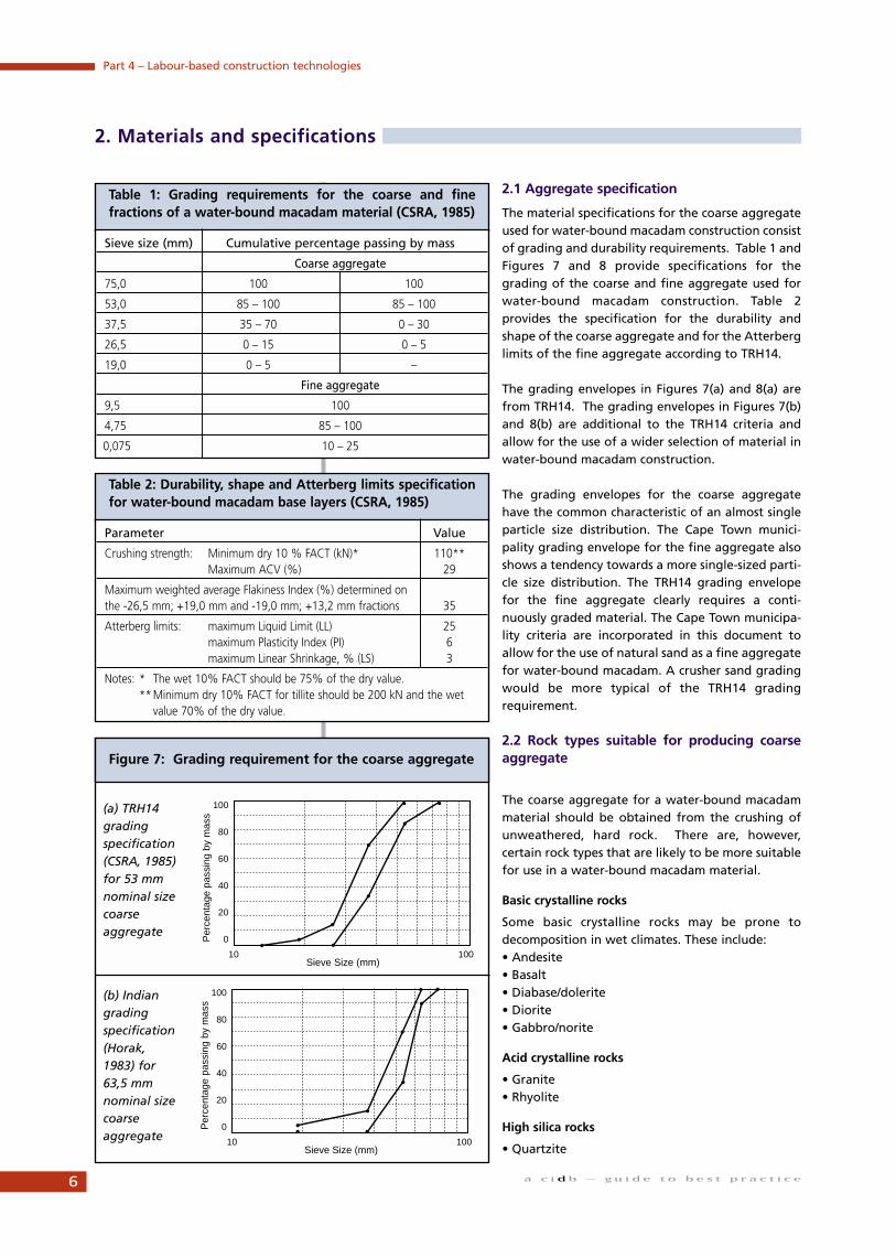
2.1 Aggregate specification
The material specifications for the coarse aggregateused for water-bound macadam construction consistof grading and durability requirements. Table 1 andFigures 7 and 8 provide specifications for thegrading of the coarse and fine aggregate used forwater-bound macadam construction. Table 2provides the specification for the durability andshape of the coarse aggregate and for the Atterberglimits of the fine aggregate according to TRH14.
The grading envelopes in Figures 7(a) and 8(a) arefrom TRH14. The grading envelopes in Figures 7(b)and 8(b) are additional to the TRH14 criteria andallow for the use of a wider selection of material inwater-bound macadam construction.
The grading envelopes for the coarse aggregatehave the common characteristic of an almost singleparticle size distribution. The Cape Town munici-pality grading envelope for the fine aggregate alsoshows a tendency towards a more single-sized parti-cle size distribution. The TRH14 grading envelopefor the fine aggregate clearly requires a conti-nuously graded material. The Cape Town municipa-lity criteria are incorporated in this document toallow for the use of natural sand as a fine aggregatefor water-bound macadam. A crusher sand gradingwould be more typical of the TRH14 gradingrequirement.
2.2 Rock types suitable for producing coarseaggregate
The coarse aggregate for a water-bound macadammaterial should be obtained from the crushing ofunweathered, hard rock. There are, however,certain rock types that are likely to be more suitablefor use in a water-bound macadam material.
Basic crystalline rocks
Some basic crystalline rocks may be prone todecomposition in wet climates. These include:• Andesite• Basalt• Diabase/dolerite• Diorite• Gabbro/norite
Acid crystalline rocks
• Granite• Rhyolite
High silica rocks
• Quartzite
a c i d b – g u i d e t o b e s t p r a c t i c e
Part 4 – Labour-based construction technologies
2. Materials and specifications
Table 1: Grading requirements for the coarse and finefractions of a water-bound macadam material (CSRA, 1985)
Sieve size (mm) Cumulative percentage passing by mass
Coarse aggregate
75,0 100 100
53,0 85 – 100 85 – 100
37,5 35 – 70 0 – 30
26,5 0 – 15 0 – 5
19,0 0 – 5 –
Fine aggregate
9,5 100
4,75 85 – 100
0,075 10 – 25
Table 2: Durability, shape and Atterberg limits specificationfor water-bound macadam base layers (CSRA, 1985)
Parameter Value
Crushing strength: Minimum dry 10 % FACT (kN)* 110**Maximum ACV (%) 29
Maximum weighted average Flakiness Index (%) determined on the -26,5 mm; +19,0 mm and -19,0 mm; +13,2 mm fractions 35
Atterberg limits: maximum Liquid Limit (LL) 25maximum Plasticity Index (PI) 6maximum Linear Shrinkage, % (LS) 3
Notes: * The wet 10% FACT should be 75% of the dry value.**Minimum dry 10% FACT for tillite should be 200 kN and the wet
value 70% of the dry value.
Figure 7: Grading requirement for the coarse aggregate
(a) TRH14gradingspecification(CSRA, 1985)for 53 mmnominal sizecoarseaggregate
(b) Indiangradingspecification(Horak,1983) for63,5 mmnominal sizecoarseaggregate
100
80
60
40
20
0
10 100Sieve Size (mm)
Per
cent
age
pass
ing
by m
ass
100
80
60
40
20
0
10 100Sieve Size (mm)
Per
cent
age
pass
ing
by m
ass
6
Arenaceous rocks
• Quartzitic sandstone
Argillaceous rocks
Only sufficiently ‘baked’ argillaceous rocks, such asMalmesbury shale, will probably be suitable(‘Malmesbury Shale’ is in fact a misnomer, as thisrock is actually hornfels and neither shale normudstone). In general, rocks from this group are notstrong enough for use in base layers and are seldomcrushed commercially.
Carbonate rocks
• Dolomite
Diamictites
• Tillite
Granite and quartzite, especially if they come frommine dump-rock, could contain excessive quantitiesof sulphide minerals. These minerals have adistinctive shiny appearance and colour, such as ironpyrite, which is gold-coloured; marcasite, which issilver-coloured and copper pyrite, which has aniridescent gold, red and green colour. Theseminerals decompose easily in the presence of water and air to form mainlysulphuric acid. The acid products are not stable and change into sulphate saltswhich may cause blistering of the surfacing. If a relatively pervious water-boundmacadam is built with clearly visible quantities of these minerals present in thecoarse aggregate, it is recommended that expert opinion be obtained, should theuse of this material be contemplated.
Although tillites have performed well in water-bound macadam base layersunder Heavy Vehicle Simulator (HVS) testing in KwaZulu-Natal (Roux and Otte,1993; Wright and Hess, 1988), the strength requirement for the use of thismaterial in base layers is increased to a minimum dry 10 per cent FACT of 200 kN,the wet 10% FACT being 70% of the dry value (CSRA, 1985).
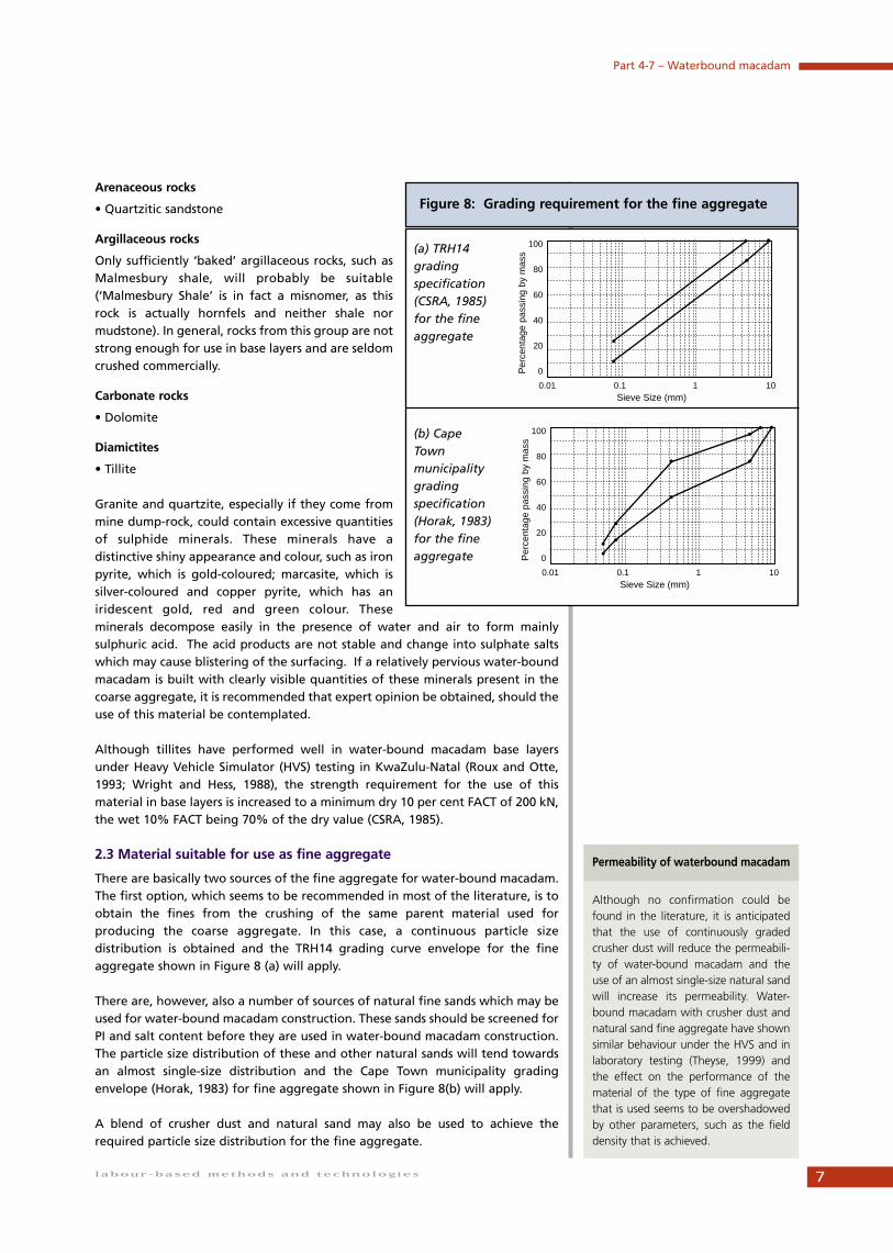
2.3 Material suitable for use as fine aggregate
There are basically two sources of the fine aggregate for water-bound macadam.The first option, which seems to be recommended in most of the literature, is toobtain the fines from the crushing of the same parent material used forproducing the coarse aggregate. In this case, a continuous particle sizedistribution is obtained and the TRH14 grading curve envelope for the fineaggregate shown in Figure 8 (a) will apply.
There are, however, also a number of sources of natural fine sands which may beused for water-bound macadam construction. These sands should be screened forPI and salt content before they are used in water-bound macadam construction.The particle size distribution of these and other natural sands will tend towardsan almost single-size distribution and the Cape Town municipality gradingenvelope (Horak, 1983) for fine aggregate shown in Figure 8(b) will apply.
A blend of crusher dust and natural sand may also be used to achieve therequired particle size distribution for the fine aggregate.
labour-based methods and technologies
Part 4-7 – Waterbound macadam
Figure 8: Grading requirement for the fine aggregate
(a) TRH14gradingspecification(CSRA, 1985)for the fineaggregate
(b) CapeTownmunicipalitygradingspecification(Horak, 1983)for the fineaggregate
Although no confirmation could befound in the literature, it is anticipatedthat the use of continuously gradedcrusher dust will reduce the permeabili-ty of water-bound macadam and theuse of an almost single-size natural sandwill increase its permeability. Water-bound macadam with crusher dust andnatural sand fine aggregate have shownsimilar behaviour under the HVS and inlaboratory testing (Theyse, 1999) andthe effect on the performance of thematerial of the type of fine aggregatethat is used seems to be overshadowedby other parameters, such as the fielddensity that is achieved.
Permeability of waterbound macadam
100
80
60
40
20
0
0.01 10Sieve Size (mm)
Per
cent
age
pass
ing
by m
ass
0.1 1
100
80
60
40
20
0
0.01 10Sieve Size (mm)
Per
cent
age
pass
ing
by m
ass
0.1 1
7

2.4 Relaxation of the TRH14 material specifications
The relaxation of the TRH14 material specifications may be viewed in terms ofdeviations from the grading requirements for the coarse and fine aggregatesand/or deviations from the strength and plasticity requirements for the coarseand fine aggregates respectively. Such relaxations should only be considered forlow volume roads. Expert opinion should be consulted whenever the use ofmarginal materials is considered.
In terms of deviations from the grading requirements for the coarse aggregate,the grading envelopes specified by most institutions seem to agree to a greatextent. The impetus for deviating from this basic grading specification seems tobe small, as the coarse aggregate is basically a manufactured material whoseparticle size distribution can be controlled. The grading specifications for the fineaggregate seem to have been adapted by local road authorities to suit thenatural sands available in specific areas. In view of the previous comment on therelatively small effect that the grading of the fine aggregate has on thebehaviour of the water-bound macadam under repeated loading, a deviationfrom the grading requirement for the fine aggregate does not seem critical.Adjustment of the grading envelope for the fine aggregate, such as the exampleshown in Figure 8, to suit locally available sands may therefore be allowed, withdue consideration being given to the effect that this may have on thepermeability of the composite material.
Although it has been suggested that the strength requirement for the largeaggregate may be too stringent (Roux and Otte, 1993), Horak (1983) reported achange in the grading of the coarse aggregate under HVS testing and Philips(1994) reported that fracturing of the coarse aggregate occurred under vibratorycompaction. It is therefore recommended that the TRH14 strength requirementsfor the coarse aggregate be adhered to.
Hefer (1997) investigated the performance of seven water-bound macadampavements in the Johannesburg area, all of which performed well. Of these, thefine aggregate in five of the water-bound macadam base layers had PI values inexcess of the specified value of 6, with values as high as 9 and 11 in some cases.Horak (1983) recommended a range of values for the PI of the fine aggregatebetween 4 and 9, the intention being that the higher PI material should be usedto reduce the water permeability of the top portion of the water-boundmacadam base layer.
8 a c i d b – g u i d e t o b e s t p r a c t i c e
Part 4 – Labour-based construction technologies
3.1 The use of water-bound macadam in wet areas
Water-bound macadam is one of the preferred base layer types in the wet climateof the eastern part of South Africa. HVS test results (Roux and Otte, 1989) andrecent laboratory test results (Theyse, 1999) indicate that water-bound macadamloses static shear strength and deforms to a significantly greater extent at highsaturation levels than at low saturation levels. It is therefore desirable to keepthe saturation level of even a water-bound macadam base layer as low as possiblein order to ensure best performance.
Although this has not been confirmed by experimental results, the permeabilityof water-bound macadam should presumably be a function of the particle sizedistribution of the fine aggregate. A water-bound macadam layer with acontinuously graded fine aggregate such as crusher sand should have a lowerpermeability than a water-bound macadam layer with an almost single-sized fineaggregate filler. It is therefore recommended that a continuously graded fineaggregate should be used as far as possible to prevent water from entering thebase layer. If, on the other hand, it is foreseen that, despite all precautions, thewater-bound macadam layer will have to perform some drainage function, thepermeability of the water-bound macadam should be sufficient to allow thewater to drain away, but not high enough to cause the transportation of the finesfrom the layer. A natural sand filler is the appropriate choice in this case.
Complete saturation of the layer with the associated high pore-pressure undertraffic loading should be avoided at all cost. Side-drains provided for drainingaway construction water should be able to accommodate the in-service drainageof the layer but these must be maintained properly.
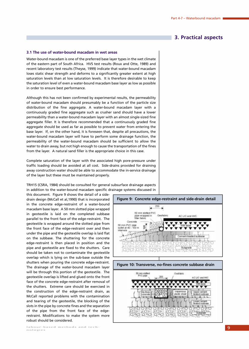
TRH15 (CSRA, 1984) should be consulted for general subsurface drainage aspectsin addition to the water-bound macadam specific drainage systems discussed inthis document. Figure 9 shows the detail of a side-drain design (McCall et al,1990) that is incorporatedin the concrete edge-restraint of a water-boundmacadam base layer. A 50 mm slotted pipe wrappedin geotextile is laid on the completed subbaseparallel to the front face of the edge-restraint. Thegeotextile is wrapped around the slotted pipe fromthe front face of the edge-restraint over and thenunder the pipe and the geotextile overlap is laid flaton the subbase. The shuttering for the concreteedge-restraint is then placed in position and thepipe and geotextile are fixed to the shutters. Careshould be taken not to contaminate the geotextileoverlap which is lying on the sub-base outside theshutters when pouring the concrete edge-restraint.The drainage of the water-bound macadam layerwill be through this portion of the geotextile. Thegeotextile overlap is lifted and glued onto the frontface of the concrete edge-restraint after removal ofthe shutters. Extreme care should be exercised inthe construction of the edge-restraint drain, asMcCall reported problems with the contaminationand tearing of the geotextile, the blocking of theslots in the pipe by concrete fines and the separationof the pipe from the front face of the edge-restraint. Modifications to make the system morerobust should be considered.
labour-based methods and tech-
nologies
Part 4-7 – Waterbound macadam
3. Practical aspects
Figure 9: Concrete edge-restraint and side-drain detail
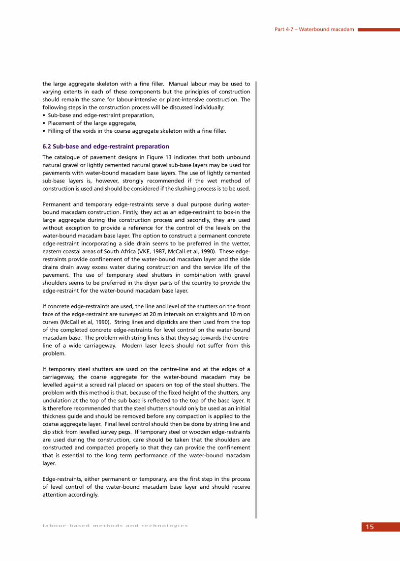
Figure 10: Transverse, no-fines concrete subbase drain
9

Figure 10 shows a section through a sub-base drainfor a water-bound macadam base layer consisting ofa transverse no-fines concrete strip, wrapped infilter fabric. The sub-base drain is easier to constructand more robust than the edge-restraint drain. Thistype of no-fines concrete drain should not be usedin the base layer, as crushing of the concrete willoccur during compaction of the water-boundmacadam base layer.
The side-drain and concrete edge-restraint shown inFigure 9 has been used successfully in KwaZulu-Natal (VKE, 1987) with a slight modification. Thedrainage pipe was moved to the bottom centre partof the concrete edge-restraint and no-fines concretewas used for the edge-restraint. As the drainagepipe and geotextile did not become clogged withconcrete fines, this system performed exceptionallywell, allowing all the construction water to drainaway under saturated conditions. The only problemwith this design was that the no-fines concrete didnot bond well to the cemented sub-base and thatthe edge-restraints moved laterally duringplacement of the base layer. It is suggested thatmetal spikes be driven into the sub-base and thatthe no-fines concrete be poured around theprotruding spikes. The suggested modified design isshown in Figure 11. Although this design performed
reasonably well during construction, there is concern that the no-fines concretewill be crushed if it is exposed to traffic loading. Figure 12 shows anotheralternative for the design of the edge-restraint drain normally used with blockpaving (Visser, personal communication).
3.2 Field density specification, compaction and quality control
The purpose of setting a certain minimum level for the density of a pavementlayer is to ensure that an adequate bearing strength is achieved. Althoughbearing strength is the desired parameter, density is a convenient parameter tomeasure under field conditions and in the laboratory and the relationshipbetween bearing strength and density can easily be confirmed from laboratorytest results. The field density specifications for water-bound macadam are basedon the apparent density of the coarse and fine aggregate combined. TRH14(CSRA 1985) makes provision for two water-bound macadam classes whosedensity requirements are:• WM1 88 – 90% of apparent density• WM2 86 – 88% of apparent density
Potgieter, Hattingh and Schultz (1997) described the four stages of water-boundmacadam compaction summarised in the list below and described how theselevels of densification could be achieved.
Loose: Loose material after placement.
Orientated: The orientation of the large aggregate is adjusted to achieve anoptimum packing pattern of the coarse and fine aggregates. This level may beachieved with light rollers.
10 a c i d b – g u i d e t o b e s t p r a c t i c e
Part 4 – Labour-based construction technologies
Figure 11: Modified VKE edge-restraint and side-draindesign
Figure 12: Block paving type edge-restraint and side-drain design

Interlocked: The large aggregate is locked into an optimum packing pattern.According to Potgieter, Hattingh and Schultz, this is the highest level ofdensification that can be achieved during construction by using heavy (12 tonne)rollers.
Densified: The air voids in the layer are minimised through the optimum packingpattern of the coarse and fine aggregates. According to Potgieter, Hattingh andSchultz, this condition will be achieved for water-bound macadam under trafficloading.
It has often been said that the large aggregate provides the bearing strength ofwater-bound macadam and that the fine aggregate provides stability to thematerial. The bearing strength is achieved through the normal forces acting atthe contact points between the large aggregate particles. Maximisation of thenumber of contact points by achieving an optimal packing pattern of the coarseaggregate in an interlocked state will therefore result in maximisation of thebearing strength. This optimal packing pattern with its associated maximumnumber of contact points and normal contact forces is, however, only maintainedthrough the frictional forces at the contact points and the stabilising effect of thefine aggregate. It is therefore essential to the performance of the water-boundmacadam that an interlocked condition be achieved with a dense filling of thevoids with the fine aggregate. The current general consensus (Visser andHattingh, 1999) is that only the use of conventional heavy compaction equipment(12-tonne flat wheel roller) will ensure the desired interlocked and stablecondition of water-bound macadam.
The use of these heavy rollers also enables the slushing of the water-boundmacadam layer to remove excess fines from the layer. The slushing process issimilar to the slushing process for a G1 crushed stone base layer and will bediscussed under the construction section of this document.
Horak (1982) investigated the effect of slushing on the density of water-boundmacadam at one HVS test site. The maximum density achieved by rolling alonewas 86,5% of apparent density, while the density increased to 88,6% afterslushing and to 89,5% after trafficking. These results seem to confirm thehypothesis by Potgieter, Hattingh and Schultz and emphasise the need to achievethe maximum possible density of the water-bound macadam layer duringconstruction before the road is opened to traffic. It is therefore recommendedthat, except in areas with water shortages, water-bound macadam should beslushed to achieve the highest possible density during construction so as to avoidpost-construction compaction and deformation of the material.
The construction quality of nine roads with labour-intensively constructed water-bound macadam base layers was evaluated for the Central WitwatersrandRegional Services Council in 1994 (van Huyssteen, 1994). Only one of the 10density samples taken from these roads complied with the density specificationof 88% of apparent density for a WM1 material and one sample met the densityspecification of 86% of apparent density for a WM2 material. It is not stated whatcompaction equipment was used on these base layers, but the field density of thewater-bound macadam clearly did not meet the specifications and Van Huyssteenconcluded that inadequate inclusion of fines in the large aggregate skeleton wasthe cause of the low field density. A localised failure occurred on one of theseroads. The fines settled to the bottom of the water-bound macadam layer underthe vibratory action of traffic. The asphalt surfacing had a cobblestoneappearance (seemingly spanning from one large stone to the next) and a densecrack pattern. This same type of localised failure has been noted on several
11labour-based methods and technologies
Part 4-7 – Waterbound macadam
The density of water-bound macadam isthe single most important factor gov-erning the performance of the material.There can therefore be no compromiseon the density specification for water-bound macadam and the use of con-ventional, heavy compaction equipmentis imperative.
Density is crucial

recently constructed water-bound macadam baselayers in the Gauteng Province (Sadzik, personalcommunication).
3.3 Selection of a surfacing type
The selection of a surfacing type for water-boundmacadam is largely dictated by the riding quality ofwater-bound macadam rather than by structuralrequirements. From previous studies the followingriding qualities are typical:• Water-bound and slurry penetration macadam:
1,5 - 2,0 PSI• Asphalt wearing course on a slurry penetration
layer: 3,0 - 3,5 PSI• Asphalt wearing course on an asphalt levelling
course: 3,5 - 4,0 PSI.
According to the constructed riding quality re-quirement from TRH4, a water-bound and slurrypenetration macadam with a single or double seal
will therefore not even satisfy the riding quality requirement for a Category Droad in a rural environment. Single or double seal surface treatments aretherefore not recommended for water-bound macadam pavements.
Slurry penetration macadam has been applied successfully as a stage constructionoption to accommodate construction traffic without disturbing the base layer(Roux and Otte, 1993). An asphalt wearing course on a slurry penetrationmacadam may be applied to category D, C and less important category B roads.Important category B roads and category A roads require both asphalt levellingand wearing courses.
Although the riding quality of a water-bound or slurry penetration macadamwith a single or double seal may be sufficient for application on streets in urbanareas, an asphalt surfacing is still recommended. The turning, breaking andaccelerating motion of traffic in the urban environment may damage surfacetreatments and expose the water-bound macadam to the scouring effects ofstormwater run-off. The placement of water-bound macadam with a paver doesnot have a significantly beneficial effect on the riding quality of the material, anacceptable riding quality only being achieved when a correction layer (hot-mixasphalt or penetration slurry) and a wearing course layer are applied.
12 a c i d b – g u i d e t o b e s t p r a c t i c e
Part 4 – Labour-based construction technologies
Inadequate filling of the voids in the water-bound macadam layer with fineaggregate and subsequent failure of the layer to meet the density specifica-tion therefore seem to be a significant problem resulting in the localized fail-ure of the water-bound macadam base layer. The construction process ofwater-bound macadam may itself lead to high spatial variability in density.The uneven spreading of the fine aggregate can result in lean patches witha lower density than that of the surrounding area and even below the spec-ified density. A density test that can be applied at a large number of pointson the layer is therefore required. The rondavel density test (Horak, 1983) isregarded as the most appropriate type of density test for water-boundmacadam. Unfortunately, this test, which is a type of sand replacement test,is cumbersome and not suited to frequent application. Nuclear density read-ings are quicker and easier to obtain. It is therefore suggested that a nucleardensity device be calibrated against the rondavel test for each specific proj-ect. The nuclear density readings could then be done at short intervals, withrondavel control tests being carried out at longer intervals. The holes for thenuclear probe should be drilled through a metal footplate to prevent themacadam layer from being disturbed.
Achieving uniform density

The purpose of structural pavement design is to make an unbiased estimate ofthe bearing capacity of layered pavement systems of different types. If thebearing capacity of a specific design is under- or overestimated in relation to thebearing capacity of alternative designs, the particular design will respectively beunfairly penalised or promoted during the economic analysis. A structural designmethod that will assess the bearing capacity of different pavement typesaccording to the same set of rules is therefore required. A mechanistic-empiricaldesign method has the potential to do this. SANRA (2000) presents a mechanistic-empirical design model for water-bound macadam material based on HeavyVehicle Simulator (HVS) and laboratory test results. This design model was usedfor the design of the structural pavement layers shown in the pavement designcatalogue in Figure 13.
The catalogue indicates the minimum material quality and layer thicknessrequirement for each combination of road category and design bearing capacity.Construction tolerances should be added to these minimum requirements toensure that the constructed layers are never thinner than the minimumrequirement given in the catalogue. The catalogue also allows the use of doubleand Cape Seals for combinations of low design-bearing capacity and for lessimportant road categories. This reflects the minimum requirement from astructural design viewpoint. A hot-mix asphalt surfacing may be required fromfunctional considerations and the reader is referred to the previous section of thisdocument for selection of an appropriate surfacing.
13labour-based methods and technologies
Part 4-7 – Waterbound macadam
4. Structural design
Figure 13: Structural design catalogue for waterbound macadam bases
ROAD PAVEMENT CLASS AND DESIGN BEARING CAPACITY (80 KN AXLES/LANE)
CATEGORY ESO.003 ESO.01 ESO.003 ESO.01 ESO.003 ES1 ES3 ES10 ES30 ES100
0.1-0.3x10⁴ 0.3-1.0x10⁴ 1.0-3.0x10⁴ 3.0-10x104 0.1-0.3x10⁶ 0.3-1.0x10⁶ 1.0-3.0x10⁶ 3.0-10x106 10-130x106 30-100x106 Foundation
A: Major interurban 30A 30A 50A
freeways and roads.125 125 150
(95% approximate 150C3125C3 150C3
design reliability) 125C3 150C3
B: Interurban S 30A 30A150G7
collectors and major125 125 125
150G9rural roads.
125C4 150C4 125C4
(90% approximate S S 125C4 G10
design reliability)100 125
150G6 150G5
C: Lightly S S 30A
trafficked100 100 125
rural roads 100C4 125C4 125C4
and strategic S S S 30A
roads. design100 100 100 125
reliability)100G6 125G6 150G5 150G5
D: Light pavement S S150G9
structures, rural75WM2* 100
access roads. 100C4` 100C4 G10(50% approximate S S S
design reliability)100 100 100
100G7 100G6 125G6
Symbol A denotes AG. AC. or AS.
AO, AP may be recommended as a surfacing measure for improved skid resistance when wet or to reduce water spray
S denotes Double Surface Treatment (seal or combinations of seal and slurry)
S1 denotes Single Surface Treatment
* If seal is used, increase C4 and G5 subbase thickness to 200 mm.
Most likely combinations of road category and design bearing capacity.

Designs were developed for two design cases. The first case consists of a WM2water-bound macadam base layer constructed on a granular sub-base orrelatively thin or weak cement-treated sub-base. The base layer is at 84% ofapparent density because of the relatively weak compaction anvil provided by thesub-base. The second case consists of a WM1 water-bound macadam base layerconstructed on a sufficiently strong compaction anvil consisting of at least 125mmof cement-treated material and the base density is 88% of apparent density.
The following plant and equipment is required:• 12 ton steel wheel roller compactor: for compacting aggregate and working
fines into voids,• Steel shuttering:for edge-restraint and thickness control during construction, • Steel rakes and shovels and wheelbarrows: for transporting, levelling and
placing aggregate,• Screeds which are used between the top of the steel shuttering and the top
of the side drain or the top of the inside edge of the concrete gutter toobtain the pre-compaction level,
• Steel gauges which are placed on top of the steel shuttering and edge ofconcrete to obtain the uniform loose level before compaction and to ensurethat the correct final compacted level is obtained,
• Water tank and heavy duty hose and fittings for the supply of water andslushing of fines.
6.1 Loss of previous generation skills
The success of early water-bound macadam construction in South Africadepended largely on the skills of the road-builders of the time. Meticulousattention was paid to the detail of each step of the construction process. Withtime and as a result of the increasing use of continuously graded crushed stonefor base layer construction, these skills were lost to the road-building industry.The interest in water-bound macadam construction was revived when job-creation became a national priority because water-bound macadam constructionis well suited to labour-intensive methods. By this time, however, the earlier skillof water-bound macadam construction had faded and with new, inexperiencedemerging contractors entering the road-building industry, the risk associatedwith water-bound macadam construction increased. It is therefore stronglyrecommended that the construction process for water-bound macadamconstruction be broken down into as many steps as possible, with the contractorand consultant paying the greatest attention to every detail of each step. As
many checks as possible should also be built into theprocess to enable the quality of the product to bemonitored continuously. It is not possible to gothrough the steps of water-bound macadamconstruction carelessly and still achieve a highquality product.
The construction of water-bound macadam may bedivided into two components, namely the placementof the large aggregate, and the filling of the voids in
14 a c i d b – g u i d e t o b e s t p r a c t i c e
Part 4 – Labour-based construction technologies
6. Construction
Three processes have been identified from the literature for filling the voidsin the large aggregate matrix:• dry method (hence the name dry-bound macadam),• a dry method, with slushing of the layer to remove excess fines once all
the voids have been filled,• a wet method, by which the fines are actually washed into the full depth
of the base layer with water.
Three processes for filling the voids
5. Plant and equipment
the large aggregate skeleton with a fine filler. Manual labour may be used tovarying extents in each of these components but the principles of constructionshould remain the same for labour-intensive or plant-intensive construction. Thefollowing steps in the construction process will be discussed individually:• Sub-base and edge-restraint preparation,• Placement of the large aggregate,• Filling of the voids in the coarse aggregate skeleton with a fine filler.
6.2 Sub-base and edge-restraint preparation
The catalogue of pavement designs in Figure 13 indicates that both unboundnatural gravel or lightly cemented natural gravel sub-base layers may be used forpavements with water-bound macadam base layers. The use of lightly cementedsub-base layers is, however, strongly recommended if the wet method ofconstruction is used and should be considered if the slushing process is to be used.
Permanent and temporary edge-restraints serve a dual purpose during water-bound macadam construction. Firstly, they act as an edge-restraint to box-in thelarge aggregate during the construction process and secondly, they are usedwithout exception to provide a reference for the control of the levels on thewater-bound macadam base layer. The option to construct a permanent concreteedge-restraint incorporating a side drain seems to be preferred in the wetter,eastern coastal areas of South Africa (VKE, 1987, McCall et al, 1990). These edge-restraints provide confinement of the water-bound macadam layer and the sidedrains drain away excess water during construction and the service life of thepavement. The use of temporary steel shutters in combination with gravelshoulders seems to be preferred in the dryer parts of the country to provide theedge-restraint for the water-bound macadam base layer.
If concrete edge-restraints are used, the line and level of the shutters on the frontface of the edge-restraint are surveyed at 20 m intervals on straights and 10 m oncurves (McCall et al, 1990). String lines and dipsticks are then used from the topof the completed concrete edge-restraints for level control on the water-boundmacadam base. The problem with string lines is that they sag towards the centre-line of a wide carriageway. Modern laser levels should not suffer from thisproblem.
If temporary steel shutters are used on the centre-line and at the edges of acarriageway, the coarse aggregate for the water-bound macadam may belevelled against a screed rail placed on spacers on top of the steel shutters. Theproblem with this method is that, because of the fixed height of the shutters, anyundulation at the top of the sub-base is reflected to the top of the base layer. Itis therefore recommended that the steel shutters should only be used as an initialthickness guide and should be removed before any compaction is applied to thecoarse aggregate layer. Final level control should then be done by string line anddip stick from levelled survey pegs. If temporary steel or wooden edge-restraintsare used during the construction, care should be taken that the shoulders areconstructed and compacted properly so that they can provide the confinementthat is essential to the long term performance of the water-bound macadamlayer.
Edge-restraints, either permanent or temporary, are the first step in the processof level control of the water-bound macadam base layer and should receiveattention accordingly.
15labour-based methods and technologies
Part 4-7 – Waterbound macadam

6.3 The placement of the coarse aggregate
The placement of the coarse aggregate may be done from stockpiles by handlabour using coal forks (Horak, 1983) (see Figures 14 and 15), with a heavy grader(VKE, 1987) if the coarse aggregate is dumped on the sub-base or by mechanicalpaver (McCall et al, 1990). The use of a mechanical paver in the case studyreported by McCall resulted in slightly better riding qualities on the surfaced roadthan the labour-intensive and plant-intensive methods.
Several authors (Horak, 1983; VKE, 1987; McCall, 1990 and VKE & McCutcheonand Associates, 1999) agree that about 33% reduction in the thickness of theloose, coarse aggregate should be allowed for during compaction. Spacers of therequired height are therefore placed on the edge-restraints and the coarseaggregate is spread to the top of the spacers by the preferred method. Beforeany compaction is done on the coarse aggregate layer, a level surface finishshould be obtained. This is done by filling in lean spots by hand labour and byremoving excess material from high spots. An uneven surface of the loose coarseaggregate layer before compaction will result in an uneven surface aftercompaction.
If the coarse aggregate stockpile is dumped directly onto the sub-base, ondelivery, it is desirable to move the entire stockpile during spreading, as otherwisethe partial compaction at the bottom of the stockpile heap will lead to greaterundulations of the final surface. Also there may be some fines within the coarsematerial that will fall to the bottom of the heap and interfere with the beddingof the coarse aggregate onto the sub-base.
One of the aspects of early water-bound macadam construction which washighlighted by Horak (1983) was that the maximum layer thickness constructed inone lift should not exceed twice the size of the coarse aggregate. This was doneto assist in the proper penetration of the layer with the fine aggregate.
Once a level surface is achieved on the loose, coarse aggregate layer, the spacersare removed from the concrete edge-restraints or the temporary shutters areremoved totally. The furrows left by the temporary shutters are then filled withloose aggregate. The coarse aggregate layer is now ready for compaction. Horak(1983) often referred to the use of 12 ton, 3-wheel rollers for the compaction ofthe coarse aggregate layer. Other sources (VKE, 1987 and McCall et al, 1990)mention the use of 8 ton tandem rollers and McCall specifically mentioned thebreaking of an unweathered dolerite coarse aggregate with an Aggregate
a c i d b – g u i d e t o b e s t p r a c t i c e
Part 4 – Labour-based construction technologies
Figure 14: Spreading of the coarse aggregate between temporary edge restraints
16

Crushing Value (ACV) of 14,4% under a 12 ton, 3-wheel roller. Phillips (1994) also reported thecrushing of the coarse aggregate under a vibratoryroller. Ideally, trial sections should be constructed todetermine the degradation of the coarse aggregateunder 12 ton or vibratory compaction. If degrada-tion of the coarse aggregate proves to be aproblem, 8 ton tandem rollers should be used.
Rolling should always be towards the higher side: ifcambered, rolling starts at the sides and progressestowards the centre; if super-elevated, it starts at thelow side and progresses upwards. If gravel shouldersare used, the drum of the roller should overlap ontothe shoulder to ensure proper confinement. Afterthe initial compaction passes the surface of the layeris again rectified by hand. Rolling is continued untilno movement of the coarse aggregate is visibleunder the rollers and the coarse aggregate is keyed in. The stone layer is then‘locked up’. It should be note that if lock-up is not achieved and the fines arespread and slushed, the shape and level of the base will be distorted by eachsubsequent operation. Lock-up ensures higher stability of the coarse aggregateand less distortion of the final surface.
6.4 Filling of the voids in the coarse aggregate with fine aggregate
The fine aggregate is spread on the keyed-in coarse aggregate layer by handusing shovels or by mechanical chip-spreader (see Figure 16). The thickness of theloose filler placed in one application should not exceed 25mm and should beevenly distributed. If the material is slightly moist, it should be left to dry beforevibratory compaction is applied to enable the fine aggregate to filter down intothe coarse aggregate layer. The process of successive applications of fineaggregate and vibratory compaction is continued until the layer is choked withfine aggregate. If the dry process is selected, the construction process stops at thispoint. The dry method is appropriate for arid areas where very little water isavailable for construction. In this case, water-bound macadam constructionshould compare favourably with the construction of a continuously gradedmaterial which will require compaction water.
If slushing is selected, the choked layer is watered and compaction should thenresume, working from the highest to the lowestpoint. Drainage outlets should be inspected toensure that the construction water drains freelyfrom the layer. The excess fines should be slushedfrom the layer and broomed to the side of the layer(see Figure 17). After completion of the slushingprocess, the layer should be left to dry and thenbroomed again.
McCall et al (1990) mentioned the use of a 24 tonpneumatic roller for the slushing process and VKE(1987) indicated that the use of a 24 ton pneumaticroller had no significant effect on the slushingprocess. Density results (Horak, 1982) from water-bound macadam base layers seem to indicate that adensity of 84% to 86% of apparent density may be
labour-based methods and tech-
nologies
Part 4-7 – Waterbound macadam
Figure 15: Levelling the loose coarse aggregate beforecompaction
Figure 16: Spreading of the fine aggregate
17

achieved with vibratory compaction using the drymethod and that a density up to 88% may beachieved if the layer is slushed and that this will befurther increased by trafficking to between 88%and 90% of apparent density. This seems to corres-pond well with Potgieter, Hattingh and Schultz’stheory of orientation, interlock and densification.
After the fine aggregate is applied to fill the voids,the layer is then ready to be primed. A blanket ofloose filler may be left on top of the layer to preventkick-out of the coarse aggregate under constructiontraffic but all loose material must be broomed offbefore the prime is applied. In general it is notrecommended that traffic is allowed on the water-bound macadam layer before the surfacing layer isapplied. This can be costly and difficult under somecircumstances. If it is foreseen that it will be difficultto prevent traffic (including construction traffic)using the road, the possibility of applying a slurrylayer across the water-bound macadam should beconsidered. This is also costly but will be cheaperthan having to do major reconstruction of thewater-bound macadam layer. McCall et al (1990)reported on the use of a slurry penetration layer inthe top portion of a water-bound macadam base
layer that was opened to construction traffic within four hours of constructionwith no damage to the base layer.
To summarise, the following list of important aspects which should be monitoredclosely during the construction process, is provided:• The edge-restraints, either permanent or temporary, form the first step in the
process of level control of the water-bound macadam base layer and shouldreceive attention accordingly,
• The maximum layer thickness constructed in one lift should not exceed twicethe size of the coarse aggregate,
• If the surface of the loose coarse aggregate layer is uneven beforecompaction, this will result in an uneven surface after compaction,
a c i d b – g u i d e t o b e s t p r a c t i c e
Part 4 – Labour-based construction technologies
Figure 17: Washing-in of the fines during thecompletely wet process
A completely wet process – KwaZulu-Natal
A completely wet process has been used in KwaZulu-Natal on twooccasions (VKE, 1987 and McCall et al 1990) when the fine aggregatewould not dry sufficiently to flow freely into the coarse aggregatelayer. A water cart with a modified spray bar was used to blast thefine aggregate into the voids with water jets. Again, if this techniqueis used, the drainage outlets should be inspected to ensure that theconstruction water drains from the base layer.
Figure 18: A completed road, showing the waterbound macadam layer after compaction, priming andsurfaced with a thin asphalt
18

• After the initial compaction passes, the surfaceof the coarse aggregate layer is again rectifiedby hand,
• Rolling is continued until no movement of thecoarse aggregate is visible under the rollers andthe coarse aggregate is keyed-in.
• The thickness of the loose filler placed in oneapplication should not exceed 25 mm and shouldbe evenly distributed,
• If a slushing process is used, compaction shouldstart from the highest point, working to thelowest point,
• If a slushing or completely wet process is used,drainage outlets should be inspected to ensurethat the construction water drains freely fromthe base layer,
• The layer must dry out completely before it issealed,
• A layer of loose filler material or a slurrypenetration layer may be used if the newly constructed water-boundmacadam layer has to be opened to construction traffic,
• All loose material must be broomed off before a prime is applied.
The density of the layer can be checked against the following requirements fromTRH 14:• WM1 88-90% of apparent density • WM2 86-88% of apparent density
Sand replacement tests or nuclear density measurements can be used todetermine density. However, as these tests can only be performed after the fineaggregate has been placed and the base slushed, it may be very difficult toimprove the density if the coarse aggregate was not compacted properly. Ifadditional slushing does not bring the density up to specification, then the layerwill have to be scrapped and new material brought in. It is generally very costlyto separate the coarse and fine materials for re-use. It is therefore important thatmeasures are in place to ensure that the coarse aggregate is sufficientlycompacted before the fine materials are placed. One important means of doingthis is using levels to ensure that the 33% reduction in thickness of the loose layerwas achieved.
All the geometric requirements of the specification must be checked and met:level, layer thickness, and eveness (with straight-edge tests). The cleanliness ofthe mosaic must also be checked carefully. Poor brooming will leave fines on thestone surface, which will lead to delamination of the surfacing.
19labour-based methods and technologies
Part 4-7 – Waterbound macadam
Figure 18: continued
7. Quality control
1. SANRA: The South African National Road Agency: Guidelines for theSelection, Design and Construction of Water-bound Macadam Base Layers,Draft Guideline Document DP-2000/5, Pretoria, 2000.
2. Burrow J C. 1975. Report on the investigation of existing road pavements inthe Transvaal. Pretoria: Transvaal Roads Department, Materials Branch.(Report L1/75)
3. COLTO (Committee of Land Transport Officials). 1996. Draft TRH4 1996:Structural design of flexible pavements for inter-urban and rural roads.Pretoria: Department of Transport.
4. CSRA (Committee of State Road Authorities). 1984. Draft TRH15 1984:Subsurface drainage for roads. Pretoria: Department of Transport.
5. CSRA (Committee of State Road Authorities), 1985. TRH14 Guidelines forroad construction materials. Pretoria: Department of Transport.
6. De Beer M, Kleyn E G and Savage P F. 1988. Towards A Classification Systemfor the Strength-balance of Thin Surfaced Flexible Pavements. In:Proceedings of the 1988 Annual Transportation Convention. Volume 3D,Paper 3D-4. Pretoria.
7. Hattingh J and Potgieter C J. 1999. Evaluation of the labour-intensive mac-adam construction technique. Preprint of paper presented at the 7thConference on Asphalt Pavements for Southern Africa. Victoria Falls,Zimbabwe.
8. Hefer A W. 1997. Towards design guidelines for macadam pavements M EngThesis, University of Pretoria.
9. Horak E. 1982. The recompaction of the 250 mm thick experimental water-bound macadam section at Mariannhill, Pinetown. Pretoria: CSIR NITRR.(Technical Note: TP/72/82)
10. Horak E. 1983. Watergebindemacadamplaveisels. M Eng Thesis, University ofPretoria.
11. Horak E, McCutcheon R T and Van Wijk, A J 1995. The philosophical approachto labour-intensive work in the Greater Johannesburg. In: Proceedings of the1995 Annual Transportation Convention. Volume 3C. Pretoria.
12. McCall J, Roux P and Currie R. 1990. Water-bound macadam in singlecarriageway highway construction in Natal. I n: Proceedings of the 1990Annual Transportation Convention. Volume 4C. Pretoria.
13. Phillips S D. 1994. Theoretical analysis of labour-intensive construction ofwater-bound macadam roads. PhD thesis. University of Witwatersrand.
14. Potgieter, Hattingh and Schultz Inc. 1997. Construction report: Road 2388labour-intensive test sections (macadam sections). Honeydew: Potgieter,Hattingh and Schultz Inc. (P H S Inc. document: W9632-1)
15. Roux P L and Otte J R 1993. Coarse aggregate bases. Pretoria: CSIR Trans-portek. (RDAC report: RR 88/027)
16. Theyse H L. 1995. TRH4 Revision (1995) Phase II: Mechanistic design analysisof the pavement structures contained in the TRH4 pavement designcatalogue. Pretoria: CSIR Transportek. (Service contract report: NSC 24/2).
20 a c i d b – g u i d e t o b e s t p r a c t i c e
Part 4 – Labour-based construction technologies
8. Specialist literature

17. Theyse H L. 1999. Laboratory design models for materials suited to labour-intensive construction, Volume I: Report, Pretoria: CSIR Transportek.(Confidential contract report: CR-99/038)
18. Theyse H L. 1999. First level report for HVS testing on the N1-28 near LouisTrichardt. Pretoria: CSIR Transportek. (Confidential contract report: CR-99/065)
19. Van Niekerk, Kleyn & Edwards. 1987. Completion report and photographicrecord of the construction of the layerworks for National Route 2 Section 23,Umgababa to Scottburgh. Durban: VKE Engineers.
20. Visser A T and Hattingh J. 1999. Design Guidelines for Low-Volume MacadamPavements in South Africa. In: Proceedings of the 7th InternationalConference on Low-Volume Roads. Transportation Research Record No. 1652,Volume 2.
21. VKE Engineers & McCutcheon and Associates. 1999. Report on labour-intensive work and contract development programme. Pretoria: VKEEngineers. (Contract No: SAPR N128005/2)
22. Wright B and Hess R. 1988. Evaluation of a freeway pavement incorporatinga water-bound macadam base. Pretoria: CSIR Division of Roads and TransportTechnology.
23. McCutcheon, RT and Taylor Parkins, FLM (Editors). Employment and High-Standard Infrastructure. Work Research Centre for Employment Creation inConstruction. School of Civil and Environmental Engineering, University ofthe Witwatersrand, 2003.
21labour-based methods and technologies
Part 4-7 – Waterbound macadam

22 a c i d b – g u i d e t o b e s t p r a c t i c e
Part 4 – Labour-based construction technologies
Notes

23labour-based methods and technologies
Part 4-7 – Waterbound macadam
Notes

24 a c i d b – g u i d e t o b e s t p r a c t i c e
Part 4 – Labour-based construction technologies
Notes

Major contributing organisations
Department of Public Works
Department of Transport
Department of Water Affairs and Forestry
Gautrans
South African National Roads Agency Limited
Soweto City Council
Johannesburg City Council
eThekwini Metro
Tshwane Metro
South African Federation of Civil Engineering
Contractors
South African Association of Consulting Engineers
South African Institution of Civil Engineering
University of the Witwatersrand
University of Pretoria
International Labour Organisation (Asist Programme)
CSIR Boutek and Transportek
Development Bank of Southern Africa
The South African Roads Board
Agrément South Africa
Standards South Africa
Cement and Concrete Institute
South African Bitumen Association
South African Black Technical and Allied Careers
Organisation
Concrete Manufacturing Association
Building Industries Federation of South Africa
National Economic Forum
National Housing Forum
Congress of South African Trade Unions
Plus many individuals from construction companies
This guide to best practice would not have been possiblewithout the contribution of all sectors of SA Constructionand its stakeholders, a contribution of time and leadershipmade in the interests of a better industry.
It is impossible to list all those who have made an input tothis product since the 1996 initiative between the Ministerof Public Works and Captains of Industry. The “Captains’Initiative” kick-started a number of key interventionstowards a transforming industry including a focus onlabour-based construction.
Initial conceptual work was taken forward by the Inter-ministerial Task on Construction Industry Development,which established a focus group under the leadership ofGraham Power. The Focus Group built on the experienceof pilot public works projects to develop a preliminary setof guidelines.
Building on the work of the Task Team, the cidb hasexpanded the application of technologies and methods toincrease the employment generated per unit of expendi-ture. A focus group of industry specialists and stakehold-ers has further reviewed and refined these guidelines,which are now recommended by the Expanded PublicWorks Programme in the delivery of national, provincialand municipal infrastructure,
cidb wishes to thank the many individuals whose passion,commitment and knowledge has enabled the develop-ment of this publication as a common resource in the fightagainst poverty and joblessness, both in South Africa andglobally.
A special thanks is due to Ron Watermeyer (past Presidentof the SA Institution of Civil Engineers) whose involve-ment has ensured a continuity of focus throughout theprocess.
Acknowledgements

“Like slavery and apartheid, poverty is not natural. It isman made and it can be overcome and eradicated bythe actions of human beings.”
Nelson Mandela, 2005 – Global Campaign for Action against Poverty