laboratory work - fitstaff.fit.ac.cy/eng.la/amem317/laboratory work - amem317.pdf · ntonios •...
TRANSCRIPT

Dr.
A
nto
nio
s L
on
tos
Machine Elements II Fig.: 1
Machine Elements and Analysis I – AMEM 317 (AUTO 309)
Laboratory Work
Dr. Antonios Lontos
Website: http://staff.fit.ac.cy//eng.la/ E-mail: [email protected], [email protected]
Dr.
A
nto
nio
s L
on
tos
Machine Elements II Fig.: 2
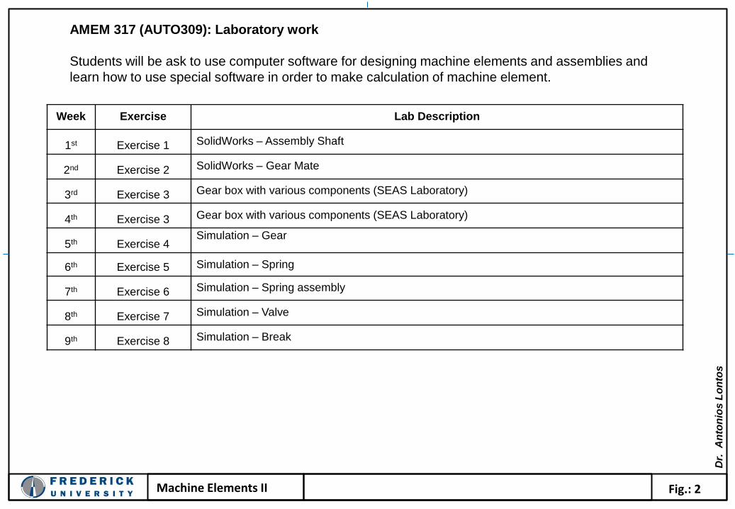
Week Exercise Lab Description
1st Exercise 1 SolidWorks – Assembly Shaft
2nd Exercise 2 SolidWorks – Gear Mate
3rd Exercise 3 Gear box with various components (SEAS Laboratory)
4th Exercise 3 Gear box with various components (SEAS Laboratory)
5th Exercise 4 Simulation – Gear
6th Exercise 5 Simulation – Spring
7th Exercise 6 Simulation – Spring assembly
8th Exercise 7 Simulation – Valve
9th Exercise 8 Simulation – Break
AMEM 317 (AUTO309): Laboratory work
Students will be ask to use computer software for designing machine elements and assemblies and
learn how to use special software in order to make calculation of machine element.
Dr.
A
nto
nio
s L
on
tos
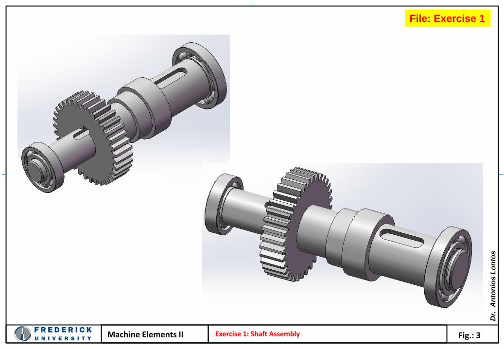
Machine Elements II Fig.: 3 Exercise 1: Shaft Assembly
File: Exercise 1

Dr.
A
nto
nio
s L
on
tos
Machine Elements II Fig.: 4 Exercise 2: Gear mate
File: Exercise 2
Straight bevel pinion 3M 18PT 36GT 20PA 20FW
Straight bevel gear 3M 36GT 18PT 20PA 20FW
Spur gear 3M 12T 20PA 12FW
Helical gear 3M 25T 45HA 20PA 20FW
Helical gear 3M 10T 45HA 20PA 20FW

Dr.
A
nto
nio
s L
on
tos
Machine Elements II Fig.: 5 Exercise 3: Design and assembly of a Gear Box
Design and assembly of a Gear Box
Each team (max 5 students) has to design the machine elements shown in the following picture. Give a name
to each component. Each team has to demonstrate one gear assembly using all the other parts from all the
teams.
Design Groups
Design Group 1: Case – Gear box
Design Group 2: Gears – Keys
Design Group 3: Caps – Screws
Design Group 4: Shafts
Design Group 5: Bearings – Spacers - Seals
Deliverables for each team:
• Draft drawings of each part (Hand sketches)
• Photos of each part at different view angles
• Construction drawings of each part
• 3D drawings each part
• One assembly manual using the drawings from other design teams

Dr.
A
nto
nio
s L
on
tos
Machine Elements II Fig.: 6 Exercise 4: Simulation case study
File: Exercise 4
Dr.
A
nto
nio
s L
on
tos
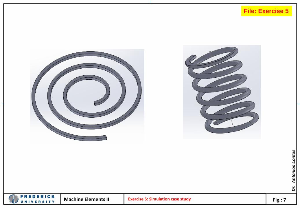
Machine Elements II Fig.: 7 Exercise 5: Simulation case study
File: Exercise 5

Dr.
A
nto
nio
s L
on
tos
Machine Elements II Fig.: 8 Exercise 6: Simulation case study
File: Exercise 6
Dr.
A
nto
nio
s L
on
tos
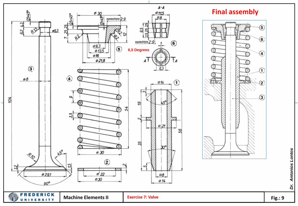
Machine Elements II Fig.: 9
Final assembly
Exercise 7: Valve
6,5 Degrees

Dr.
A
nto
nio
s L
on
tos
Machine Elements II Fig.: 10 Exercise 7: Simulation Valve
Apply Force
Apply fix boundary conditions
6,5 Degrees
File: Exercise 7

Dr.
A
nto
nio
s L
on
tos
Machine Elements II Fig.: 11 Exercise 8: Simulation case study
File: Exercise 8