laboratory chamber & tube furnaces - laboline furnaces.pdfteam of qualified engineers based at...
TRANSCRIPT

Laboratory Chamber & Tube Furnaces
OPTIONAL
CONTROL & RECORD
nanodac™
NEW
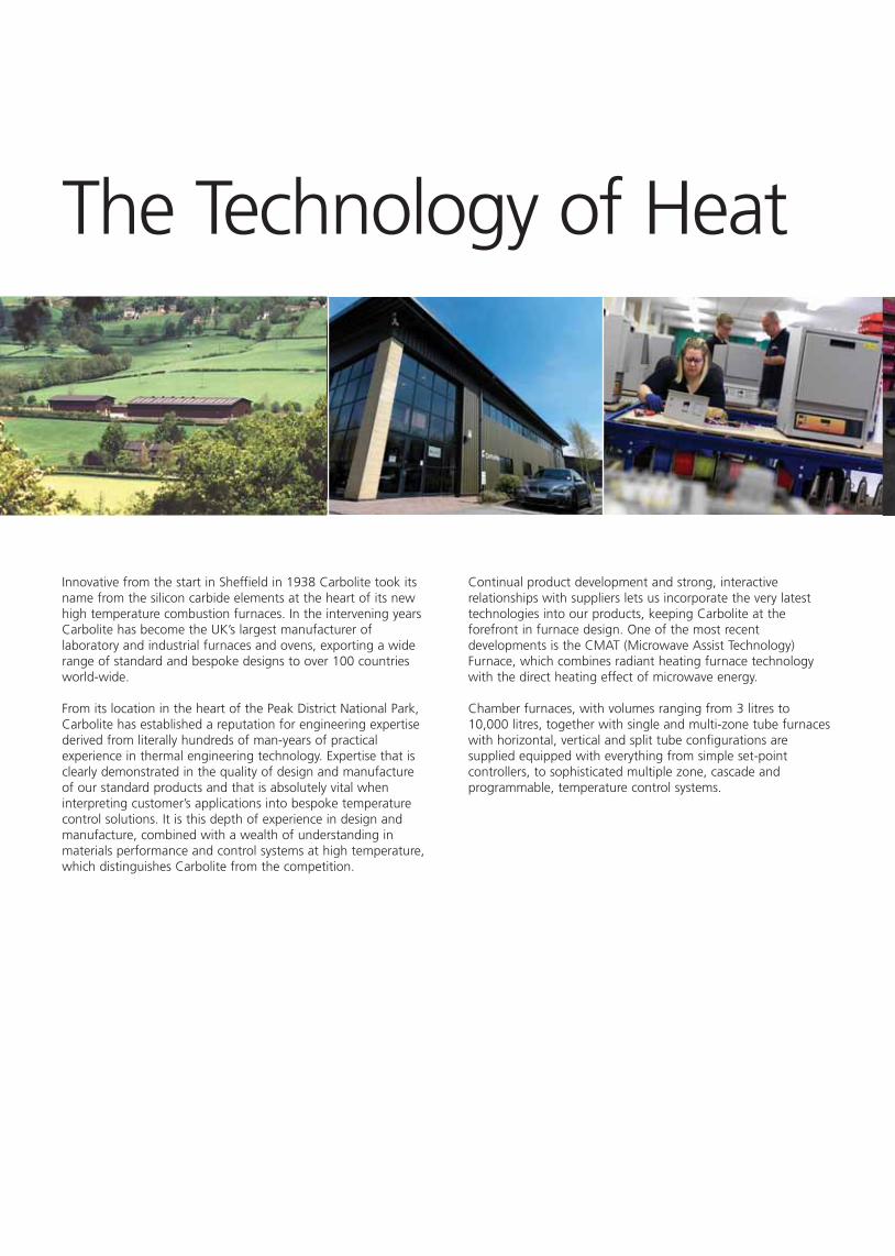
Innovative from the start in Sheffield in 1938 Carbolite took itsname from the silicon carbide elements at the heart of its newhigh temperature combustion furnaces. In the intervening yearsCarbolite has become the UK’s largest manufacturer oflaboratory and industrial furnaces and ovens, exporting a widerange of standard and bespoke designs to over 100 countriesworld-wide.
From its location in the heart of the Peak District National Park,Carbolite has established a reputation for engineering expertisederived from literally hundreds of man-years of practicalexperience in thermal engineering technology. Expertise that isclearly demonstrated in the quality of design and manufactureof our standard products and that is absolutely vital wheninterpreting customer’s applications into bespoke temperaturecontrol solutions. It is this depth of experience in design andmanufacture, combined with a wealth of understanding inmaterials performance and control systems at high temperature,which distinguishes Carbolite from the competition.
The Technology of Heat
Continual product development and strong, interactiverelationships with suppliers lets us incorporate the very latesttechnologies into our products, keeping Carbolite at theforefront in furnace design. One of the most recentdevelopments is the CMAT (Microwave Assist Technology)Furnace, which combines radiant heating furnace technologywith the direct heating effect of microwave energy.
Chamber furnaces, with volumes ranging from 3 litres to10,000 litres, together with single and multi-zone tube furnaceswith horizontal, vertical and split tube configurations aresupplied equipped with everything from simple set-pointcontrollers, to sophisticated multiple zone, cascade andprogrammable, temperature control systems.

In addition to versatile general laboratory products Carbolitealso manufacture a range of application specific furnaces forsuch uses as Clean Room installations, Strip and Rotary Hearthand Rotary Tube furnaces. As well as for standard complianttesting such as Ashing, Coal & Coke standard analysistechniques, Iron Ore Reduction, Precious Metals Assay, AsphaltBinder Analysis, Tensile Testing and much more.
Carbolite’s flexibility and capability to solve customer’s individualapplication requirements have given its products an importantplace in chemical, materials science, engineering and industrialresearch, testing and development laboratories, as well as forpilot and production scale manufacturing within aerospace,automotive, surface treatment, tooling, ceramics, glass,pharmaceutical, chemicals, plastics, engineering, electronics,mining & extraction, iron & steel, as well as coal & cokeindustries around the World.
R
Carbolite not only regularly supplies products with standardscompliant furnace designs, such as for NADCAP (AMS2750D)heat treatment processes, but can also supply fully traceablecertification for control, measurement, recording and dataacquisition devices, issued by an independent UKAS / NAMASaccredited laboratory.
All of the products featured in this catalogue and more, areavailable through an extensive worldwide network of dealersand local offices. Carbolite’s factory trained field engineersprovide a complete range of after sales support and technicaladvice and guidance on product selection is available from ateam of qualified engineers based at Hope or via our websitewww.carbolite.com

R
www.carbolite.com
Page
3 Bespoke Furnaces
4 Chamber Furnace Selection5 ELF 1100° Chamber Furnaces 6 CWF 1100°C, 1200°C & 1300°C General Purpose Chamber Furnaces7 RWF 1100°C & 1200°C Rapid Heating Chamber Furnaces8 GPC 1200°C & 1300°C Larger Capacity Laboratory Chamber Furnaces9 VCF 1200°C Top Loading Chamber Furnaces
10 HRF 750°C Air Recirculating Chamber Furnaces11 LTH 1100°C & 1200°C Top Hat Chamber Furnaces
12/13 RHF 1400°C, 1500°C & 1600°C Silicon Carbide Heated Furnaces14 MRF 16/22 CMAT 1600°C Microwave Assist Furnace15 CMAT – Carbolite Microwave Assist Technology16 HTF 1700°C & 1800°C High Temperature Chamber Furnaces17 BLF 1700°C & 1800°C Bottom Loading Furnaces
18 Ashing & Burn-off Furnaces19 AAF 1100°C Ashing & Burn-off Furnaces20 ABF 8/28 800°C Afterburner Ashing Furnace 21 GSM 1100°C Ashing & Burn-off Furnace22 AAF 12/18 1200°C Ashing-Plus Furnace 23 BWF 1100°CV & 1200°C Ashing & Burn-off Furnaces
24 Tube Furnace Selection25 MTF 900°C, 1000°C, 1200°C Wire Wound Single Zone Tube Furnaces26 CTF 1200°C Wire Wound Single Zone Tube Furnaces27 GHA 1200°C Single Zone Horizontal Tube Furnaces28 GVA 1200°C Single Zone Versatile Configuration Tube Furnaces 29 GHC 1200°C Wire Embedded Single Zone Tube Furnaces30 GVC 1200°C Wire Embedded Versatile Configuration Three Zone Tube Furnaces31 HST 1200°C Horizontal Single Zone Split Tube Furnaces32 VST 1200°C Versatile Single Zone Split Tube Furnaces33 TZF 1200°C Wire Wound Horizontal Three Zone Tube Furnaces34 EVT 1100°C Elevator Tube Furnace35 HZS & TVS 1200°C Wire Embedded Versatile Configuration Three Zone Split Tube Furnaces
36/37 STF 1500°C & 1600°C High Temperature Single Zone Tube Furnaces38 VST 1700°C High Temperature Single Zone Split Tube Furnace39 CTF 1700°C & 1800°C High Temperature Horizontal Tube Furnaces40 PVT 1800°C High Temperature Vertical Tube Furnaces41 TZF 1500°C 1600°C, 1700°C & 1800°C High Temperature Three Zone Horizontal Tube Furnace42 HVT 1200°C & 1500°C High Vacuum Tube Furnaces43 HTR 1100°C Rotary Reactor Furnaces44 SPTF Rotating Tube Furnace
45 Application Specific Furnaces46 PTC 12/20 1200°C Portable Thermocouple Calibration Furnace47 AGD 12/4 1200°C Acid Gas Determinator Furnace48 CF 1200°C Cupellation Furnaces for the Assay of Precious Metals
Options49 Temperature Control Options50 Temperature Control & Data Recording / Acquisition51 Temperature Control & Data Recording / Acquisition
52/53 Tube Furnace Options & Accessories for Air, Modified Atmosphere & Vacuum54/55 Tube Furnace Options, Work Tubes, Temperature & Chemical Compatibility
56 Tube Furnace Options, Work Tube Accessories57 Tube Furnace Options, Mounting Configurations58 Furnace Options, Working With Modified Atmosphere
- 2 -

R
www.carbolite.com
TUBE FURNACES
TUBE FURNACE OPTIONS
APPLICATION SPECIFIC FURNACES
FURNACE OPTIONS & EXTRAS
CHAMBER FURNACES
ASHING & BURN-OFF FURNACES
BESPOKE FURNACESBESPOKE FURNACES
CUPELLATION FURNACES
Construction of standard laboratory furnaces is only part of thepicture for Carbolite. We are regularly asked to design furnaceseither to meet specific the requirements of specific customer’sapplications, or to enable the use standard test methods such asthose for iron ore reduction or coal and coke testing.
Similarly when customers must perform operations withinstandards compliant regimes such as AMS 2750D or NADCAPfor heat treatment applications, then Carbolite has theexperience and skills to modify standard designs or engineerbespoke solutions in order to achieve the appropriate levels ofcompliance.
Perhaps most frequent of all is the situation where customerssee a standard model but simply require it a little larger orsmaller or to reach a higher temperature. So if you cannot seeprecisely what you need in our standard range simply get intouch.
A 4 LANE STRIP FURNACE TO OPERATE AT 1100°C
COMBINED TEST UNIT FOR ISO 4695 IRONORE REDUCIBILITY & ISO 4696-1
LOW TEMPERATURE DISINTEGRATION
TUMBLER FOR ISO 4696-1 TESTING
THERMAL CYCLING TEST FURNACE TO CYCLETHERMOCOUPLES BETWEEN UP TO 1200°C &
AMBIENT FOR 1000S OF CYCLES
LARGE CAPACITY 1200°C FURNACE WITHMODIFIED ATMOSPHERE RETORT
HIGH TEMPERATURE 1500°C SPLIT TUBE FURNACE FOR
EXTENSION TESTING
THREE ZONE 1200°C TUBE FURNACE WITH WATER COOLING
ROTATING HEARTH FURNACE
LARGER CAPACITY ROTATING TUBE FURNACE
THERMAL TEST RIG FOR THECALIBRATION OF THERMAL
INDICATOR PAINTS
- 3 -

TUBE FURNACES
TUBE FURNACE OPTIONS
APPLICATION SPECIFIC FURNACES
FURNACE OPTIONS & EXTRAS
CHAMBER FURNACESCES
ASHING & BURN-OFF FURNACES
CHAMBER FURNACES
BESPOKE FURNACES
CUPELLATION FURNACES
Temperature Control
� Carbolite furnaces are supplied as standard with accurate PID(proportional, integral and derivative) single ‘ramp to set-point’ controllers providing accurate control and negligibleovershoot of the set temperature.
� Multisegment and or multi-programme controllers areavailable as an alternative option for most models.
� Wherever a furnace will be left operating unattended, orwhere the user wishes to protect a valuable workload or thefurnace elements from damage from accidental overheating,then an over-temperature protection device is stronglyrecommended.
Application Specific & Bespoke Designs
� Carbolite both designs and builds all of the furnaces withinthe catalogue range, therefore many ‘off the shelf’modifications are available as well as fully bespokecustomised furnaces for specific customer applications.
� Carbolite can provide a variety of mechanisms for loadingand unloading items from the furnace or for the automationof temperature cycling or quenching.
Temperature
� At Carbolite all products that heat above 600°C usingradiant (rather than convection) heating are classified asfurnaces.
� Carbolite chamber furnaces are available with maximumoperating temperatures from 750°C to 1,800°C.
� The chart indicates the models with their maximumoperating temperatures and heating method.
� Continuous operation of a furnace at its maximumtemperature will reduce its working life. Continuousoperating temperature is should be approximately 100°Cbelow maximum.
� Furnaces are designed and calibrated to operate at hightemperatures. Continuous operation below furnacetemperatures (of approximately 600°C) will be less accurateand may reduce element life in high temperature furnaces.
� Each furnace has a uniform working volume; this is a threedimensional region that is controlled within the specifiedtolerances for temperature uniformity. Select a chamberwhere this uniform volume is large enough to accommodatethe item/s to be heated.
Chamber Design
� The simplest and least expensive options are frontopening designs with side hinged doors.
� Front opening ‘up and away’ vertical lifting doors keepthe heated door surface away from the operatoroffering increased operator comfort and safety.
� Where tall objects and crucibles need lifting in and outof the chamber, vertical loading chambers with heatingelements in the side are available.
� Bottom loading or ‘raised hearth’ furnaces offer theability to rapidly heat items by lifting them up into thechamber or lowering the hearth to cool them.
� For heavier loads, moving the furnace chamber using atop hat design is a more practical solution.
Modified Atmosphere
� To work with inert gases or a modified atmospherespecify one of the following modifications at the time ofordering
� A gasket sealed or sand sealed retort in a frontopening chamber furnace
� An inverted crucible on a modified hearth in a bottomloading or top hat furnace.
Selection of a Furnace
Factors for Chamber Furnace� Chamber furnaces enable larger or more awkwardly shaped loads to be heated.
� The size of the chamber and how it is to be loaded and unloaded determine which style of furnaceis best for a given application.
� For applications involving chemical vapours, gases or humidity always check with Carbolite or yourlocal dealer which furnaces and elements will be best for your application.
700
800°C
700°C
900°C
1000°C
1100°C
1200°C
1300°C
1400°C
1500°C
1600°C
1700°C
1800°C
WIRE WOUND SILICON CARBIDE MOLYBDENUM DISILICIDE
Element Type
Max
Tem
pera
ture
HRF
ELFAAF 11
CWFVCFAAF
12/18BWF11/13GSM11/8
RWFLTH
GPC 12BWF12/13
GPC 13
RHF
HTF BLF
Heat TreatmentAshing & Heat TreatmentAshing
ABF8/28
- 4 -
R
www.carbolite.com
TUBE FURNACES
TUBE FURNACE OPTIONS
APPLICATION SPECIFIC FURNACES
FURNACE OPTIONS & EXTRAS
CHAMBER FURCHAMBER FURNACESCES
ASHING & BURN-OFF FURNACES
CHAMBER FURNACES
BESPOKE FURNACES
CUPELLATION FURNACESELF Chamber Furnaces
- 5 -
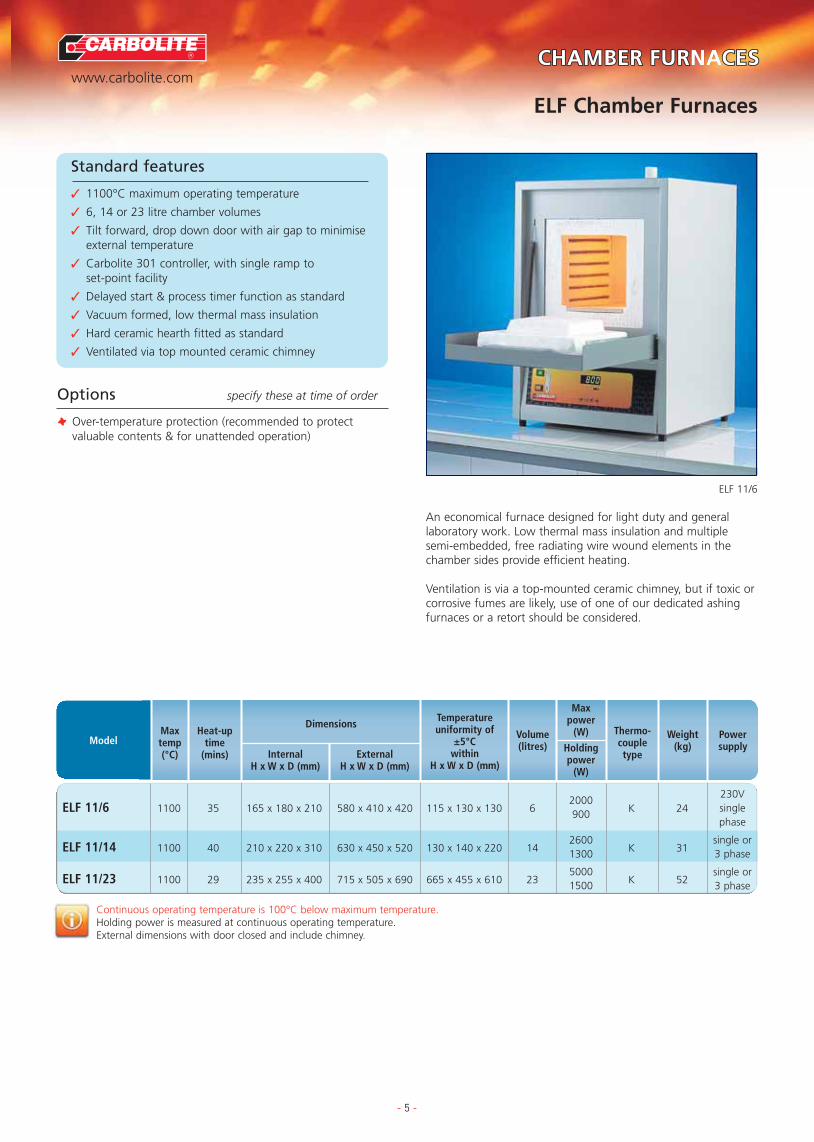
Standard features
✓ 1100°C maximum operating temperature
✓ 6, 14 or 23 litre chamber volumes
✓ Tilt forward, drop down door with air gap to minimiseexternal temperature
✓ Carbolite 301 controller, with single ramp to set-point facility
✓ Delayed start & process timer function as standard
✓ Vacuum formed, low thermal mass insulation
✓ Hard ceramic hearth fitted as standard
✓ Ventilated via top mounted ceramic chimney
ELF 11/6
Options specify these at time of order
T Over-temperature protection (recommended to protectvaluable contents & for unattended operation)
An economical furnace designed for light duty and generallaboratory work. Low thermal mass insulation and multiplesemi-embedded, free radiating wire wound elements in thechamber sides provide efficient heating.
Ventilation is via a top-mounted ceramic chimney, but if toxic orcorrosive fumes are likely, use of one of our dedicated ashingfurnaces or a retort should be considered.
Continuous operating temperature is 100°C below maximum temperature.Holding power is measured at continuous operating temperature.External dimensions with door closed and include chimney.
230Vsinglephase
single or3 phase
single or3 phase
ModelMaxtemp(°C)
Heat-uptime
(mins)
Dimensions
InternalH x W x D (mm)
ExternalH x W x D (mm)
Temperatureuniformity of
±5°Cwithin
H x W x D (mm)
Volume(litres)
Powersupply
Weight(kg)
Thermo-coupletype
Maxpower
(W)
Holdingpower
(W)
ELF 11/6 1100 35 165 x 180 x 210 580 x 410 x 420 115 x 130 x 130 62000
K 24900
ELF 11/14 1100 40 210 x 220 x 310 630 x 450 x 520 130 x 140 x 220 142600
K 311300
ELF 11/23 1100 29 235 x 255 x 400 715 x 505 x 690 665 x 455 x 610 235000
K 521500

TUBE FURNACES
TUBE FURNACE OPTIONS
APPLICATION SPECIFIC FURNACES
FURNACE OPTIONS & EXTRAS
CHAMBER FURCHAMBER FURNACESCES
ASHING & BURN-OFF FURNACES
CHAMBER FURNACES
BESPOKE FURNACES
CUPELLATION FURNACES
R
www.carbolite.com
CWF General Purpose Chamber Furnaces
- 6 -
Standard features
✓ 1100°C, 1200°C or 1300°C maximum operatingtemperature
✓ 5, 13 or 23 litre chamber volumes
✓ Up & away door keeps heated surface away from the user
✓ Carbolite 301 controller with single ramp to set-point facility
✓ Delayed start & process timer function
✓ Hard wearing alumina element carriers, furnaceentrance & hearth
✓ Energy efficient low thermal mass insulation
✓ Free radiating wire wound elements pitched foroptimum uniformity
✓ Easy access to elements & controls simplifiesmaintenance & servicing
CWF 12/13/301
Options specify these at time of order
T Over-temperature protection (recommended to protectvaluable contents & for unattended operation)
T 2 phase supply
T 8 or 20 segment programmer
T RS232 communications
T A variety of retorts & modifications are available for workingwith modified atmospheres
A modern design is combined with traditional know-how &technology, to provide a robust and reliable furnace. Easy toaccess replaceable heating modules makes maintenance simple.
Continuous operating temperature is 100°C below maximum temperature.Holding power is measured at the continuous operating temperature.
CWF 11/5 1100 30 135 x 140 x 250585 x 375 x 485
85 x 90 x 110 52400
K 30(800) 790
CWF 11/13 1100 80 200 x 200 x 325655 x 435 x 610
120 x 120 x 185 133100
K 47(905) 1500
CWF 11/23 1100 40 235 x 245 x 400705 x 505 x 675
155 x 165 x 285 237000
K 68(990) 1900
CWF 12/5 1200 35 135 x 140 x 250585 x 375 x 485
85 x 90 x 125 52400
R 30(800) 850
CWF 12/13 1200 65 200 x 200 x 325655 x 435 x 610
120 x 120 x 200 133100
R 47(905) 1550
CWF 12/23 1200 45 235 x 245 x 400705 x 505 x 675
155 x 165 x 325 237000
R 68(990) 2250
CWF 13/5 1300 40 135 x 140 x 250585 x 375 x 485
85 x 90 x 150 52400
R 30(800) 1000
CWF 13/13 1300 80 200 x 200 x 325655 x 435 x 610
120 x 120 x 225 133100
R 47(905) 1800
CWF 13/23 1300 55 235 x 245 x 400705 x 505 x 675
155 x 165 x 340 237000
R 68(990) 2500
‘Universal’ models are easily altered between single phase (220V), 3 phase+neutral (e.g. 380/220V) and delta (e.g. 220V) electrical supplies
230Vsingle phase
230V single or2 phase
Universal
230Vsingle phase
230V single or2 phase
Universal
230Vsingle phase
230V single or2 phase
Universal
ModelMaxtemp(°C)
Heat-uptime
(mins)
Dimensions
InternalH x W x D (mm)
ExternalH x W x D (mm)H (door open)
Temperatureuniformity of
±5°Cwithin
H x W x D (mm)
Volume(litres) Power supply
Weight(kg)
Thermo-coupletype
Maxpower
(W)
Holdingpower
(W)

R
www.carbolite.com
TUBE FURNACES
TUBE FURNACE OPTIONS
APPLICATION SPECIFIC FURNACES
FURNACE OPTIONS & EXTRAS
CHAMBER FURCHAMBER FURNACESCES
ASHING & BURN-OFF FURNACES
CHAMBER FURNACES
BESPOKE FURNACES
CUPELLATION FURNACESRWF Rapid Heating Chamber Furnaces
- 7 -
Standard features
✓ 1100°C or 1200°C maximum operating temperature
✓ 5, 13 or 23 litre chamber volumes
✓ Ambient to 1100°C in as little as 10 minutes
✓ Rapid thermal response from free radiating coiled wire elements
✓ Low thermal mass insulation for fast response & energy efficiency
✓ Up & away door keeps heated surface away from the user
✓ Carbolite 301 controller with single ramp to set-point & process timer
✓ Hard wearing, dust free hearth
✓ Easy access to elements & controls simplifiesmaintenance & servicing
RWF 12/5/301
Options specify these at time of order
T Over-temperature protection (recommended to protectvaluable contents & for unattended operation)
T 2 phase supply at no extra cost above 13 litres
T 8 or 20 segment programmer
T RS232 communications
T A variety of retorts & modifications is available for workingwith modified atmospheres Free radiating wire-wound elements and highly efficient low
thermal mass insulation are combined to provide a furnace forlight to medium laboratory applications where rapid thermalresponse is important.
Continuous operating temperature is 100°C below maximum temperature.Holding power is measure at continuous operating temperature.
RWF 11/5 1100 10 130 x 160 x 250585 x 375 x 485
52750
K 28230V
(800) 680 single phase
RWF 11/13 1100 11 195 x 210 x 325655 x 435 x 610
135000
K 45230V single or
(905) 1200 2 phase
RWF 11/23 1100 13 220 x 260 x 400705 x 505 x 675
239100
K 65 Universal(990) 1800
RWF 12/5 1200 12 130 x 160 x 250585 x 375 x 485
52750
R 28230V
(800) 820 single phase
RWF 12/13 1200 13 195 x 210 x 325655 x 435 x 610
135000
R 45230V single or
(905) 1450 2 phase
RWF 12/23 1200 15 220 x 260 x 400705 x 505 x 675
239100
R 65 Universal(990) 2100
‘Universal’ models are easily altered between single phase (220V), 3 phase+neutral (e.g. 380/220V) and delta (e.g. 220V) electrical supplies
ModelMaxtemp(°C)
Heat-uptime
(mins)
Dimensions
InternalH x W x D (mm)
ExternalH x W x D (mm)H (door open)
Volume(litres) Power supplyWeight
(kg)
Thermo-coupletype
Maxpower
(W)
Holdingpower
(W)

TUBE FURNACES
TUBE FURNACE OPTIONS
APPLICATION SPECIFIC FURNACES
FURNACE OPTIONS & EXTRAS
CHAMBER FURCHAMBER FURNACESCES
ASHING & BURN-OFF FURNACES
CHAMBER FURNACES
BESPOKE FURNACES
CUPELLATION FURNACES
R
www.carbolite.com
GPC Larger Capacity Laboratory Chamber Furnaces
- 8 -
Standard features
✓ 1200°C or 1300°C maximum operating temperature
✓ 36, 65, 131 or 200 litre chamber volumes
✓ Free radiating coiled wire elements
✓ Low thermal mass insulation for fast response & energy efficiency
✓ Up & away door, keeps heated surface away from the user
✓ Carbolite 301 controller, with single ramp to set-point & process timer
✓ Hard wearing refractory hearth plate, resists damage &supports heavier loads
✓ Heating elements are easily serviced from the front ofthe chamber
GPC 12/36/3216P1
Options specify these at time of order
T Over-temperature protection (recommended to protectvaluable contents & for unattended operation)
T 8 or 20 segment programmer
T RS232 communications
T A range of inconel (NiCr) retorts to work with modifiedatmospheres up to 1100°C
Designed for general workshop and laboratory use, the GPCrange has the styling and features of the laboratory furnacerange with the advantages of a larger chamber size and higherloading capacity.
Continuous operating temperature is 100°C below maximum temperature.Holding power is measured at continuous operating temperature.
GPC 12/36 1200 37 250 x 320 x 450 36 9000 R 100 Universal
GPC 12/65 1200 40 278 x 388 x 595 65 14000 R 165 3 phase
GPC 12/131 1200 150 350 x 500 x 750 131 18000 R 400 3 phase
GPC 12/200 1200 – 400 x 600 x 900 200 24000 R 518 3 phase
GPC 13/36 1300 47 250 x 320 x 450 36 9000 R 120 Universal
GPC 13/65 1300 45 278 x 388 x 595 65 14000 R 165 3 phase
GPC 13/131 1300 – 350 x 500 x 750 131 18000 R 400 3 phase
‘Universal’ models are easily altered between single phase (220V), 3 phase+neutral (e.g. 380/220V) and delta (e.g. 220V) electrical supplies
ModelMaxtemp(°C)
Heat-uptime
(mins)
Dimensions
InternalH x W x D (mm)
ExternalH x W x D (mm)H (door open)
Volume(litres) Power supplyWeight
(kg)
Thermo-coupletype
Maxpower
(W)
810 x 690 x 780(1105)
885 x 780 x 945(1245)
1652 x 1110 x 1280(2310)
Floorstanding
1702 x 1350 x 1350(2410)
Floorstanding
810 x 690 x 780(1105)
885 x 780 x 945(1245)
1652 x 1110 x 1280(2310)
Floorstanding

R
www.carbolite.com
TUBE FURNACES
TUBE FURNACE OPTIONS
APPLICATION SPECIFIC FURNACES
FURNACE OPTIONS & EXTRAS
CHAMBER FURCHAMBER FURNACESCES
ASHING & BURN-OFF FURNACES
CHAMBER FURNACES
BESPOKE FURNACES
CUPELLATION FURNACESVCF Top Loading Laboratory Chamber Furnaces
- 9 -
Standard features
✓ 1200°C maximum operating temperature
✓ 5, 10, 23 or 100 litre chamber volumes
✓ Free radiating wire elements in all 4 sides of chamber
✓ Vented top opening door
✓ Angled control panel, protected but clearly visible
✓ Carbolite 301 controller, with single ramp to set-point & process timer
✓ Thermocouple protected by ceramic sheath
✓ Top accessible elements for easy servicing
VCF 12/5/3508/P10
Options specify these at time of order
T Over-temperature protection (recommended to protectvaluable contents & for unattended operation)
T 8 or 20 segment programmer
T RS232 communications
A floor standing furnace design which is particularly suitable forapplications involving tall crucibles or heavy samples, where thetop loading format makes sample handling much easier.
Continuous operating temperature is 100°C below maximum temperature.Holding power is measured at the continuous operating temperature.
VCF 12/5 1200 102 260 x 155 x 130 52500
R 50Single
900 phase
VCF 12/10 1200 138 365 x 180 x 155 103000
R 60Single
1200 phase
VCF 12/23 1200 125 450 x 250 x 200 236000
R 130Optional
2500 Universal
VCF 12/100 1200 150 600 x 410 x 410 10015000
R 200 3 phase6000
‘Universal’ models are easily altered between 1 phase (220V), 3 phase+neutral (e.g. 380/220V) and delta (e.g. 220V) electrical supplies
ModelMaxtemp(°C)
Heat-uptime
(mins)
Dimensions
InternalH x W x D (mm)
ExternalH x W x D (mm)H (door open)
Volume(litres)
Powersupply
Weight(kg)
Thermo-coupletype
Maxpower
(W)
Holdingpower
(W)
660 x 530 x 405–
Floorstanding
765 x 555 x 430(910)
Floorstanding
850 x 600 x 500–
Floorstanding
1100 x 930 x 950–
Floorstanding
TUBE FURNACES
TUBE FURNACE OPTIONS
APPLICATION SPECIFIC FURNACES
FURNACE OPTIONS & EXTRAS
CHAMBER FURCHAMBER FURNACESCES
ASHING & BURN-OFF FURNACES
CHAMBER FURNACES
BESPOKE FURNACES
CUPELLATION FURNACES
R
www.carbolite.com
HRF Air Recirculating Chamber Furnaces
- 10 -
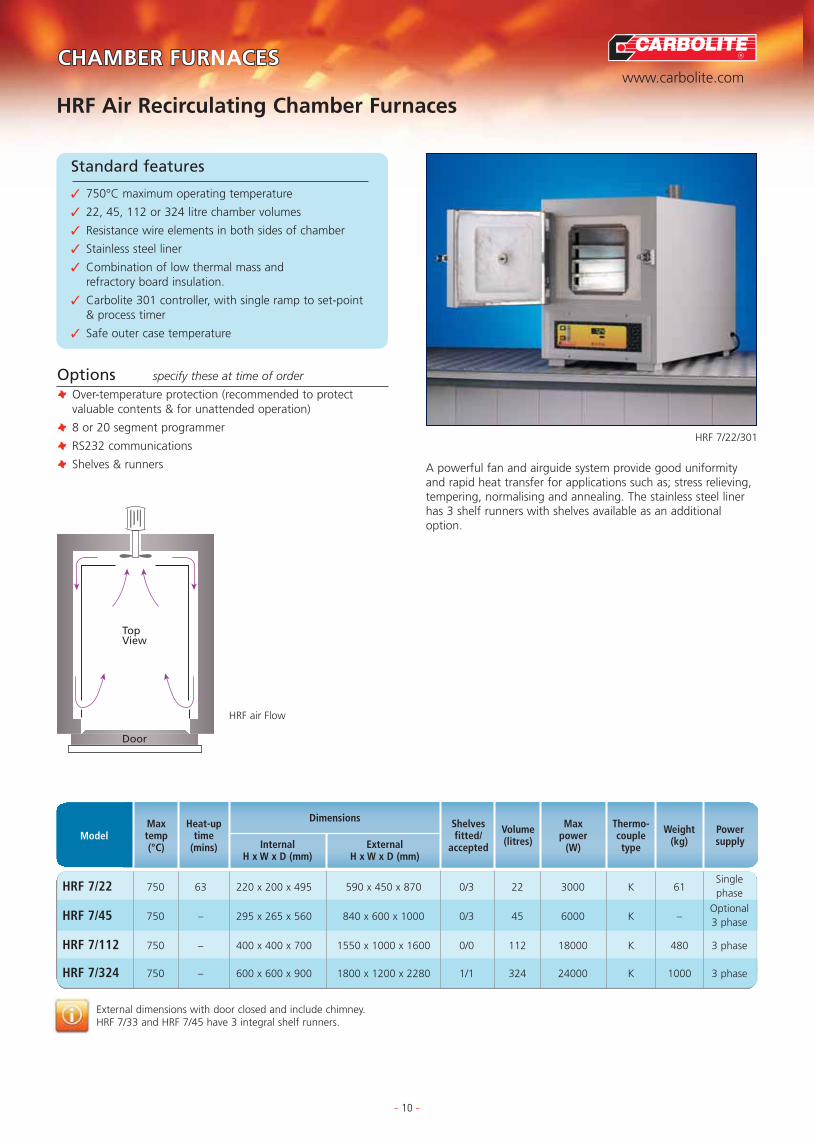
Standard features
✓ 750°C maximum operating temperature
✓ 22, 45, 112 or 324 litre chamber volumes
✓ Resistance wire elements in both sides of chamber
✓ Stainless steel liner
✓ Combination of low thermal mass and refractory board insulation.
✓ Carbolite 301 controller, with single ramp to set-point & process timer
✓ Safe outer case temperature
HRF 7/22/301
HRF air Flow
Options specify these at time of order
T Over-temperature protection (recommended to protectvaluable contents & for unattended operation)
T 8 or 20 segment programmer
T RS232 communications
T Shelves & runners A powerful fan and airguide system provide good uniformityand rapid heat transfer for applications such as; stress relieving,tempering, normalising and annealing. The stainless steel linerhas 3 shelf runners with shelves available as an additionaloption.
External dimensions with door closed and include chimney.HRF 7/33 and HRF 7/45 have 3 integral shelf runners.
HRF 7/22 750 63 220 x 200 x 495 590 x 450 x 870 0/3 22 3000 K 61Singlephase
HRF 7/45 750 – 295 x 265 x 560 840 x 600 x 1000 0/3 45 6000 K –Optional3 phase
HRF 7/112 750 – 400 x 400 x 700 1550 x 1000 x 1600 0/0 112 18000 K 480 3 phase
HRF 7/324 750 – 600 x 600 x 900 1800 x 1200 x 2280 1/1 324 24000 K 1000 3 phase
ModelMaxtemp(°C)
Heat-uptime
(mins)
Dimensions
InternalH x W x D (mm)
ExternalH x W x D (mm)
Volume(litres)
Shelvesfitted/
accepted
Powersupply
Weight(kg)
Thermo-coupletype
Maxpower
(W)
Door
TopView

R
www.carbolite.com
TUBE FURNACES
TUBE FURNACE OPTIONS
APPLICATION SPECIFIC FURNACES
FURNACE OPTIONS & EXTRAS
CHAMBER FURCHAMBER FURNACESCES
ASHING & BURN-OFF FURNACES
CHAMBER FURNACES
BESPOKE FURNACES
CUPELLATION FURNACESLTH Top Hat Chamber Furnaces
- 11 -
Standard features
✓ 1100°C or 1200°C maximum operating temperature
✓ 3.5, 31 & 49 litre chamber
✓ Rapid heating powerful free radiating wire elements &efficient low thermal mass insulation
✓ Rapid sample cooling can be achieved by raising thechamber
✓ Electrically elevated element chamber (the 3.5 litrechamber raises or lowers in 5 seconds)
✓ Chamber rises to full internal height for easy loading
✓ All around heating chamber provides maximum heattransfer & uniformity
✓ During loading, elements switch off & are fully retracted
✓ Separate control module on 2 metre conduit for 3.5, 31& 49 litre models
✓ Hard wearing ceramic hearth
✓ Two handed elevator operation, with audible alarm andemergency stop button, for operator safety (except forLTH 12/3)
LTH 11/31 + STAND
LTH 11/49
LTH 12/3
Options specify these at time of order
T Over-temperature protection (always recommended forunattended operation or protection of valuable samples)
T Optional gas inlet
T Refractory metal bell jar to improve gas usage whenworking with modified atmosphere
T 8 or 20 segment programmer
T RS232 communications
T Optional leg extension stand for LTH/31 (illustrated)
This furnace configuration enables very easy sample loading andrapid heating and cooling from lowering and raising the heatedchamber on the hearth. It is also ideal for use with a modifiedatmosphere using an inverted crucible and optional gas inlethearth.
Continuous operating temperature is 100°C below maximum temperate.
LTH 12/3 1200 —- 200 x 150655 x 410 x 540
3.5 3000 R 38Single
222 x 570 x 375 phase
LTH 11/31 1100 — 500 x 250 x 2501900 x 500 x 600
31 8000 N 3 phase370 x 225 x 375
LTH 11/49 1100 — 400 x 350 x 350 2200 x 640 x 1057 49 9000 N 3 phase
ModelMaxtemp(°C)
Heat-uptime
(mins)
Dimensions
InternalH x W x D (mm)
ExternalH x W x D (mm)
Volume(litres)
Powersupply
Weight(kg)
Thermo-coupletype
Max power (W)

TUBE FURNACES
TUBE FURNACE OPTIONS
APPLICATION SPECIFIC FURNACES
FURNACE OPTIONS & EXTRAS
CHAMBER FURCHAMBER FURNACESCES
ASHING & BURN-OFF FURNACES
CHAMBER FURNACES
BESPOKE FURNACES
CUPELLATION FURNACES
R
www.carbolite.com
Typically reaching 1400°C in under 40 minutes the RHF rangeprovides rapid heating and is ideally suited to the rigorous firingcycles demanded from laboratory furnaces.
RHF Silicon Carbide Heated Furnaces to 1600°C
- 12 -
Standard features
✓ 1400°C, 1500°C or 1600°C maximum operatingtemperature
✓ 3, 8, 15 or 35 litre chamber volumes
✓ Silicon carbide heating elements, providing long life atelevated temperatures & able to withstand the stressesof intermittent operation
✓ Carbolite 301 PID controller, with single ramp to set-point & process timer
✓ Controllers extend heating performance bycompensating for the effects of element ageing
✓ Hard wearing refractory brick hearth and door surrounds
✓ Low thermal mass chamber insulation for energyefficiency & rapid heating & cooling
RHF 16/3/3508P1
Options specify these at time of order
T 2 phase electrical supply for 3 litre models (& for RHF 14/8)
T Over-temperature protection (recommended to protectvaluable contents & for unattended operation)
T 8 or 20 segment programmer
T RS232, RS485 communications
T A range of furnace tables & floor stands are available
Power Supplies for Silicon Carbide FurnacesThe characteristics of the control systems that are used withsilicon carbide elements result in maximum power supplyrequirements that are not as intuitively derived as those forfurnaces using other heating technologies. For this reason a moredetailed description of the maximum power supply that isrequired per phase has been included in the specification table.

R
www.carbolite.com
TUBE FURNACES
TUBE FURNACE OPTIONS
APPLICATION SPECIFIC FURNACES
FURNACE OPTIONS & EXTRAS
CHAMBER FURCHAMBER FURNACESCES
ASHING & BURN-OFF FURNACES
CHAMBER FURNACES
BESPOKE FURNACES
CUPELLATION FURNACESRHF Silicon Carbide Heated Furnaces to 1600°C
- 13 -
Continuous operating temperature is 100°C below maximum temperature.Holding power is measured at the continuous operating temperature.
a1=Single 200-240V, a2=380-415V 2 phase + N, a3=200-240V 3 phase delta, b3=200-208V 3 phase delta, d3=200-220V 3 phase delta, e3=230-240V 3 phase delta, g3=380-415V 3 phase no N, h3=380-415V 3 phase + N, j3=440-480V 3 phase no N, k3=440-480V 3 phase + N
RHF 14/3 1400 33 120 x 120 x 205655 x 435 x 610
2.94500
R 42(905) 1900
RHF 14/8 1400 22 170 x 170 x 270705 x 505 x 675
7.88000
R 64(990) 3200
RHF 14/15 1400 35 220 x 220 x 310810 x 690 x 780
1510000
R 125(1105) 2900
RHF 14/35 1400 38 250 x 300 x 465885 x 780 x 945
3516000
R 179(1245) 6000
RHF 15/3 1500 45 120 x 120 x 205655 x 435 x 610
2.94500
R 46(905) 2000
RHF 15/8 1500 40 170 x 170 x 270705 x 505 x 675
7.88000
R 61(990) 3500
RHF 15/15 1500 46 220 x 220 x 310810 x 690 x 780
1510000
R 125(1105) 3000
RHF 15/35 1500 46 250 x 300 x 465885 x 780 x 945
3516000
R 178(1245) 6200
RHF 16/3 1600 42 120 x 120 x 205655 x 435 x 610
2.94500
R 42(905) 2300
RHF 16/8 1600 35 170 x 170 x 270705 x 505 x 675
7.88000
R 61(990) 4000
RHF 16/15 1600 58 220 x 220 x 310810 x 690 x 780
1510000
R 140(1105) 3500
RHF 16/35 1600 56 250 x 300 x 465885 x 780 x 945
3516000
R 179(1245) 1100
ModelMaxtemp(°C)
Heat-uptime
(mins)
Dimensions
InternalH x W x D (mm)
ExternalH x W x D (mm)H (door open)
Volume(litres)
Weight(kg)
Thermo-coupletype
Max power(W)
SupplyRequired
(W)
Power supplyrequired per phase
a1=30A, a2=15A
a1=50A, a2=25A
a1=62A, h3=22A, d3=38A
h3=35A, d3=60A, k3=35A
a1=36A, a2=18A
h3=17.5A, d3=30A, b3=38A, g3=17.5A
a1=75A, h3=25A, e3=43A
h3=35A e3=60A, g3=35A, j3=5A
a1=36A, a2=8A, a3=30A
h3=18A, e3=29A, b3=34A,g3=18A, k3=18A
a1=73A, h3=25A, a3=42A, k3=25A
h3=40A, e3=62A, g3=37A, k3=40A

TUBE FURNACES
TUBE FURNACE OPTIONS
APPLICATION SPECIFIC FURNACES
FURNACE OPTIONS & EXTRAS
CHAMBER FURCHAMBER FURNACESCES
ASHING & BURN-OFF FURNACES
CHAMBER FURNACES
BESPOKE FURNACES
CUPELLATION FURNACES
R
www.carbolite.com
MRF 16/22 CMAT Microwave Assist Technology Furnace
- 14 -
Standard features
✓ 1600°C maximum operating temperature
✓ Purpose built design, revolutionary microwave assisttechnology furnace
✓ Simultaneous direct heating of microwave susceptiblematerials & radiant heating by molybdenum disilicideelements
✓ Independent control of microwave & radiant heating
✓ 20 Segment programmable PID control
✓ Over-temperature protection
✓ Manual or programmable control of both heat sources
✓ Double safety interlock cuts power on door opening
✓ Safety limits for microwave containment to BS EN60519-6:2002 part 6.1 (emissions <5mW/cm2 @ 50mm)
MRF 16/22
Options specify these at time of order
T Ability to store & re-use additional programs
T Fixed or wheeled stands
T DAQ or graphical recorders
T Microwave test meter
T RS232 or RS485 communications
The capability to heat samples using the combined effects ofradiant heating and direct microwave heating using a purposebuilt MAT (Microwave Assist Technology) furnace.
Independent control of radiant heating and either continuous orpulsed microwave energy from 0 to 100% of output level.
MRF 16/22 1600 12 9 1.8 2450 232 x 245 x 396 1090 x 910 x 925 22 7.5 290 3 phase
ModelMaxtemp(°C)
Heat-uptime
(mins)
Dimensions
InternalH x W x D (mm)
ExternalH x W x D (mm)
Volume(litres)
Powersupply
NetWeight
(kg)
Maxdistributed
load(kg)
Radiantheatingpower(kW)
Micropower(kW)
MicroFreq’y(MHz)
from Carbolite

R
www.carbolite.com
TUBE FURNACES
TUBE FURNACE OPTIONS
APPLICATION SPECIFIC FURNACES
FURNACE OPTIONS & EXTRAS
CHAMBER FURCHAMBER FURNACESCES
ASHING & BURN-OFF FURNACES
CHAMBER FURNACES
BESPOKE FURNACES
CUPELLATION FURNACESCMAT – Carbolite Microwave Assist Technology
- 15 -
Background
Carbolite CMAT furnaces have been developed to use incombination, radiant heating elements and microwaveenergy using a method pioneered by UK technology andinnovation company C-Tech*.
Having tested prototype furnaces and kilns they soughtorganisations able to commercialise the concept in astandard furnace design. Carbolite holds the Europeanlicence to develop and commercialise this technology andfrom this has developed our CMAT furnaces. Our strongworking relationship with the North American licenceholder who offers support means that Carbolite is able tosupply the unique benefits of the MRF 16/22 world wide.
The Benefits of MAT (Microwave Assist Technology) The MRF offers the potential for improved:
V Sintering densities at lower temperatures, using lessenergy.
V Sequential removal of binder (burn-off) and sintering, by preferentially heating binders.
V Reduced energy consumption by rapid direct heating ofthe sample.
V More uniform heating effects throughout the sampleproviding similar crystal structure and phase boundaryproperties at the surface and within the sample interior.
In a conventional furnace when the surface of a sample isheated by radiation the internal volume of the sample onlyheats through conduction. The limiting speed ofconduction causes a thermal gradient to form which can
result in early surface hardening followed by cracking andbloating of the surface.
In the CMAT, sample materials which are susceptible tomicrowave interaction couple with the microwave energyto cause frictional heating at the molecular levelthroughout the volume of the sample.
To be susceptible to microwave heating a material shouldhave components which have a high dielectric potential butwhere the molecular structure produces enough frictionalresistance to these components aligning with the oscillatingmicrowave energy for frictional heating to occur.
The MRF 16/22 uses a 2.45 MHz magnetron emittingenergy at 1.8kW to generate this effect, in addition tomolybdenum disilicide radiant heating elements. Unlikedevices which simply use microwaves to heat susceptibleblocks which then radiate heat onto the sample, the CMATfurnace is able to heat the sample using both infraredradiant heat and microwaves. The MRF 16/22’s fully flexibleprogrammable controller enables the sequence, intensityand phasing (pulsed or continuous microwave) of theradiant and microwave heating effects to be combined withunmatched flexibility.
The MRF 16/22 is unique in concept yet manufactured to astandard repeatable design.
*C-Tech Innovation LimitedCapenhurst Technology ParkCapenhurstChesterCH1 6EH
HTPowerSupply
CONTROL
Time Heat

TUBE FURNACES
TUBE FURNACE OPTIONS
APPLICATION SPECIFIC FURNACES
FURNACE OPTIONS & EXTRAS
CHAMBER FURCHAMBER FURNACESCES
ASHING & BURN-OFF FURNACES
CHAMBER FURNACES
BESPOKE FURNACES
CUPELLATION FURNACES
R
www.carbolite.com
HTF High Temperature Chamber Furnaces
- 16 -
HTF 17/10/3216P1
Standard features
✓ 1700°C & 1800°C maximum operating temperature
✓ From 4 to 27 litre capacities
✓ Outstanding performance from molybdenum disilicideheating elements
✓ Up & away parallel opening door keeps hot face awayfrom user
✓ Compatible with intermittent or continuous use
✓ Advanced refractory interior, used in combination withenergy efficient low thermal mass insulation
✓ 8 Segment programmable controller with separateover-temperature protection
✓ Digital RS232 communications (HTF17/5, HTF17/10,HTF18/4 & HTF18/8)
✓ Fan cooling for low external case temperature.
Options specify these at time of order
T Optional 2 phase electrical supply for 3 litre models (& for RHF 14/8)
T 20 Segment programmable controller
T RS232 & RS485 communications (RHF17/25, HTF18/15 &HTF18/27)
T Fieldbus & Ethernet connectivity
T A range of data acquisition devices & chart recorders
Suitable for either intermittent or continuous operations, thesefurnaces provide dependable high temperature performancewith programmable control and overtemperature protection asstandard.
HTF 17/5 1700 50 158 x 150 x 225 5 4050 Standard B 109 Single
HTF 17/10 1700 44 227 x 200 x 225 10 5920 Standard B 176Single or2 phase
RHF 17/25 1700 45 300 x 275 x 300 25 9600 Option B 515 3 phase
HTF 18/4 1800 65 140 x 140 x 190 4 4650 Standard 20/40 175 Single phase
HTF 18/8 1800 56 210 x 190 x 190 8 6200 Standard 20/40 331Single or2 phase
HTF 18/15 1800 70 220 x 220 x 300 15 7900 Option 20/40 365Single,
2 or 3 phase
HTF 18/27 1800 55 300 x 300 x 300 27 8180 Option 20/40 509 3 phase
Continuous operating temperature is 100°C below maximum temperature.
ModelMaxtemp(°C)
Heat-uptime
(mins)
Dimensions
InternalH x W x D (mm)
ExternalH x W x D (mm)H (door open)
Volume(litres)
Maxpower
(W)Power supply
Weight(kg)
Thermo-coupletype
DigitalRS232Comms
HTF 18/27/3216P1
565 x 830 x 650(850)
565 x 830 x 650(850)
1800 x 1100 x 680(2600) Floor
565 x 830 x 650(850)
565 x 830 x 650(1105)
1580 x 690 x 800(1105) Floor
1610 x 780 x 945(1245) Floor
R
www.carbolite.com
TUBE FURNACES
TUBE FURNACE OPTIONS
APPLICATION SPECIFIC FURNACES
FURNACE OPTIONS & EXTRAS
CHAMBER FURCHAMBER FURNACESCES
ASHING & BURN-OFF FURNACES
CHAMBER FURNACES
BESPOKE FURNACES
CUPELLATION FURNACESBLF Bottom Loading Furnaces
- 17 -
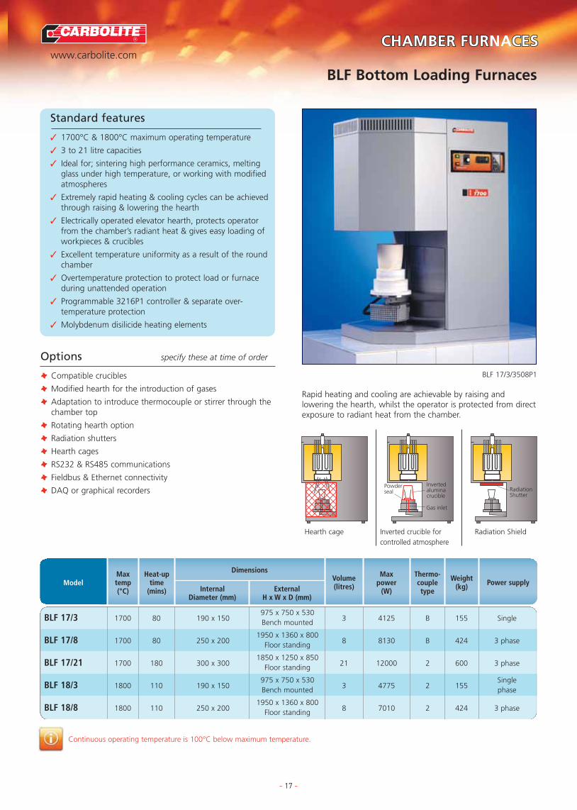
Standard features
✓ 1700°C & 1800°C maximum operating temperature
✓ 3 to 21 litre capacities
✓ Ideal for; sintering high performance ceramics, meltingglass under high temperature, or working with modifiedatmospheres
✓ Extremely rapid heating & cooling cycles can be achievedthrough raising & lowering the hearth
✓ Electrically operated elevator hearth, protects operatorfrom the chamber’s radiant heat & gives easy loading ofworkpieces & crucibles
✓ Excellent temperature uniformity as a result of the roundchamber
✓ Overtemperature protection to protect load or furnaceduring unattended operation
✓ Programmable 3216P1 controller & separate over-temperature protection
✓ Molybdenum disilicide heating elements
BLF 17/3/3508P1
Options specify these at time of order
T Compatible crucibles
T Modified hearth for the introduction of gases
T Adaptation to introduce thermocouple or stirrer through thechamber top
T Rotating hearth option
T Radiation shutters
T Hearth cages
T RS232 & RS485 communications
T Fieldbus & Ethernet connectivity
T DAQ or graphical recorders
Rapid heating and cooling are achievable by raising andlowering the hearth, whilst the operator is protected from directexposure to radiant heat from the chamber.
Continuous operating temperature is 100°C below maximum temperature.
BLF 17/3 1700 80 190 x 150975 x 750 x 530
3 4125 B 155 Single Bench mounted
BLF 17/8 1700 80 250 x 2001950 x 1360 x 800
8 8130 B 424 3 phaseFloor standing
BLF 17/21 1700 180 300 x 3001850 x 1250 x 850
21 12000 2 600 3 phaseFloor standing
BLF 18/3 1800 110 190 x 150975 x 750 x 530
3 4775 2 155Single
Bench mounted phase
BLF 18/8 1800 110 250 x 2001950 x 1360 x 800
8 7010 2 424 3 phaseFloor standing
ModelMaxtemp(°C)
Heat-uptime
(mins)
Dimensions
InternalDiameter (mm)
ExternalH x W x D (mm)
Volume(litres) Power supplyWeight
(kg)
Thermo-coupletype
Maxpower
(W)
Powderseal
Invertedaluminacrucible
Gas inlet
RadiationShutter
Hearth cage Inverted crucible forcontrolled atmosphere
Radiation Shield
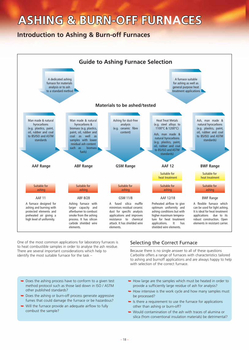
One of the most common applications for laboratory furnaces isto heat combustible samples in order to analyse the ash residue.There are several important considerations which help toidentify the most suitable furnace for the task –
Introduction to Ashing & Burn-off Furnaces
- 18 -
TUBE FURNACES
TUBE FURNACE OPTIONS
APPLICATION SPECIFIC FURNACES
FURNACE OPTIONS & EXTRAS
CHAMBER FURNACES
ASHING & BURN-OFF FURASHING & BURN-OFF FURNACESCES
BESPOKE FURNACES
CUPELLATION FURNACES
ASHING & BURN-OFF FURNACES
Selecting the Correct Furnace
Because there is no single answer to all of these questionsCarbolite offers a range of furnaces with characteristics tailoredto ashing and burnoff applications and are always happy to helpwith selection of the correct furnace.
A dedicated ashingfurnace for materials
analysis or to ash to a standard method
A furnace suitable for ashing as well as general purpose heat treatment applications
AAF Range ABF Range GSM Range AAF 12 BWF Range
Suitable for heat treatment
Suitable for heat treatment
Suitable for ashing
Suitable for ashing
Suitable for ashing
Suitable for ashing
Suitable for ashing
AAF 11 ABF 8/28 GSM 11/8 AAF 12/18 BWF Range
Guide to Ashing Furnace Selection
Materials to be ashed/tested
Man made & natural hyrocarbons
(e.g. plastics, paint, oil, rubber and coal to BS/ISO and ASTM
standards
Man made & natural hyrocarbons &
biomass (e.g. plastics, paint, oil, rubber and coal as well as samples with lower residual ash content
such as biomass fuels)
Ashing for dust-free analysis
(e.g. ceramic fibre content)
Heat Treat Metals(e.g. steel alloys to
1100°C & 1200°C)
Ash, man made & natural hyrocarbons
(e.g. plastics, paint, oil, rubber and coal to BS/ISO and ASTM
standards)
Ash, man made & natural hyrocarbons
(e.g. plastics, paint, oil, rubber and coal to BS/ISO and ASTM
standards)
A furnace designed for ashing and burning with protected elements and preheated air giving a high level of uniformity.
Ashing furnace with larger capacity and afterburner to combust smoke from the ashing process. It has silicon carbide shielded wire elements.
A fused silica muffle minimises residual ceramic dust for specific analysis applications and improves resistance to chemical attack. It has shielded wire elements.
Preheated airflow to give optimum uniformity and ashing conditions but with higher maximum tempera-ture for heat treatment applications. It has shielded wire elements.
A flexible furnace which can be used for light ashing. It is ideal for heat treatment applications due to its robust construction. Open elements in resistant carrier.
➥ Does the ashing process have to conform to a given testmethod protocol such as those laid down in ISO / ASTMother published standards?
➥ Does the ashing or burn-off process generate aggressivefumes that could damage the furnace or be hazardous?
➥ Will the furnace provide an adequate airflow to fullycombust the sample?
➥ How large are the samples which must be heated in order toprovide a sufficiently large residue of ash for analysis?
➥ How intensive is the work cycle and how many samples mustbe processed?
➥ Is there a requirement to use the furnace for applicationsother than ashing or burn-off?
➥ Would contamination of the ash with traces of alumina orsilica (from conventional insulation materials) be detrimental?

R
www.carbolite.com
TUBE FURNACES
TUBE FURNACE OPTIONS
APPLICATION SPECIFIC FURNACES
FURNACE OPTIONS & EXTRAS
CHAMBER FURNACES
ASHING & BURN-OFF FURASHING & BURN-OFF FURNACESCES
BESPOKE FURNACES
CUPELLATION FURNACES
ASHING & BURN-OFF FURNACES
AAF Ashing & Burn-off Furnaces
- 19 -
Standard features
✓ 1100°C maximum operating temperature
✓ Ideal for ashing foods, plastics, coal & otherhydrocarbon materials
✓ Designed to comply with BS 1016-104.4:1998, ISO 1171:1997, ASTM D2361-02, & ASTM D3174-04 (3 & 7 Litre models only)
✓ Wire elements are protected from chemical &mechanical damage by a hard wearing alumina based liner
✓ AAF 11/18 offers increased protection of the elementsfrom carbon & corrosive atmospheres using siliconcarbide tiles.
✓ Air inlet & tall chimney give airflow of 4 to 5 changesper minute (AAF11/3)
✓ Low chamber height holds airflow close to samples foroptimum combustion
✓ Powerful elements with graded winding compensate forheat loss due to high airflow
✓ Preheating of air before it enters the chamber givesexcellent uniformity
✓ Large floor area allows for large number of samples
✓ AAF 11/18 has two tier shelf doubling sample capacity
✓ Racks & hearth trays as belowAAF 11/7/301
TRAYS SUPPLIED WITH FURNACES
Standard accessories2 tier rack Non-perforated Perforatedsystem for sample trays sample trays LoadingModel
sample trays (qty) (qty) handlewith 80mm gap w x d (mm) w x d (mm)
AAF 11/3 – (x1) 133 x 200 – (x1)
AAF 11/7 – (x1) 163 x 326 – (x1)
AAF 11/18 (x1) – (x2) 163 x 326 (x1)
Continuous operating temperature is 100°C below maximum temperature.Holding power is measured at the continuous operating temperature.
ModelMaxtemp(°C)
Heat-uptime
(mins)
Dimensions
InternalH x W x D (mm)
ExternalH x W x D (mm)H (door open)
Volume(litres)
Powersupply
Weight(kg)
Thermo-coupletype
Max power(W)
Holdingpower
(W)
Options specify these at time of order
T 2 phase electrical supply for AAF 11/7
AAF 11/3 1100 140 90 x 150 x 250 32100
K 22 Single 1270
AAF 11/7 1100 155 90 x 170 x 455 74000
K 632300
AAF 11/18 1100 70 235 x 196 x 400 187080
K 70 Universal3500
‘Universal’ models are easily altered between single phase (220V), 3 phase+neutral (e.g. 380/220V) and delta (e.g. 220V) electrical supplies
A tall, 50mm diameter chimneypulls the air through thechamber silently and reliably.
Pre-heated air enters thechamber after circulating
around the outsideof the muffle.
585 x 375 x 485(800)
780 height to top of chimney
650 x 430 x 740(905)
1060 height to top of chimney
705 x 505 x 675(990)
1015 height to top of chimney
Single /2 phase

R
www.carbolite.com
TUBE FURNACES
TUBE FURNACE OPTIONS
APPLICATION SPECIFIC FURNACES
FURNACE OPTIONS & EXTRAS
CHAMBER FURNACES
ASHING & BURN-OFF FURASHING & BURN-OFF FURNACESCES
BESPOKE FURNACES
CUPELLATION FURNACES
ASHING & BURN-OFF FURNACES
- 20 -
Standard features
✓ 800°C maximum operating temperature – ashingchamber
✓ 28 Litre chamber volume
✓ Afterburner rated for up to 40g carbon per ashing load
✓ 3216P1 Programmable controller
✓ Independent control of afterburner temperature up to950°C
✓ Silicon carbide shielded wire wound elements
✓ Silicon carbide hearth
✓ Mesh sample trays & loading handle
ABF 8/28
ABF Afterburner Ashing Furnace
Holding power is measured at 500°C.
ABF 8/28 800 210 x 290 x 445 980x600x750 288000
K 120 Universal3828
‘Universal’ models are easily altered between single phase (220V), 3 phase + neutral (e.g. 380/220V) and delta (e.g. 220V) electrical supplies
ModelMaxtemp(°C)
Dimensions
InternalH x W x D (mm)
ExternalH x W x D (mm)
Volume(litres)
Thermo-coupletype
Max power(W)
Holdingpower
(W)
Powersupply
Weight(kg)
Options specify these at time of order
T Over-temperature protection (recommended to protectvaluable contents & for unattended operation)
T Optional dual level rack and sample trays
T Optional three phase operation
T Optional floor stand
The ABF 8/28 offers a 28 litre chamber with large floor spaceand a fan assisted pre-exhaust afterburner to combust smokebefore it exits from the chimney.
Standard accessories
Supplied with 2 tier stacking mesh sample trays (each 60 x 270 x 300) H x W x D mm and loading handle.

R
www.carbolite.com
TUBE FURNACES
TUBE FURNACE OPTIONS
APPLICATION SPECIFIC FURNACES
FURNACE OPTIONS & EXTRAS
CHAMBER FURNACES
ASHING & BURN-OFF FURASHING & BURN-OFF FURNACESCES
BESPOKE FURNACES
CUPELLATION FURNACES
ASHING & BURN-OFF FURNACES
GSM Ashing & Burn-off Furnaces
- 21 -
Standard features
✓ 1100°C maximum operating-temperature
✓ Fused quartz furnace chamber, ideal for analyses whereAl2O3 or SiO2 could contaminate test results
✓ Chamber lining offers superior containment of corrosive& aggressive vapours such as H2SO4, HNO3, HCL
✓ Moulded ceramic fibre door plug
GSM 11/8
Options specify these at time of order
T Gas Inlet for modified atmospheres (the fused quartz linerprovides improved containment)
T Sample trays & racks as below
For advice on managing corrosive oraggressive materials (within your furnace),please contact Carbolite
Continuous operating-temperature is 100°C below maximum temperature.Holding power is measured at the continuous operating-temperature.
GSM 11/8 1100 70 120 x 175 x 345 83050
K 57 Single1700
655 x 435 x 740(990)
1060mm height to top of chimney
Optional accessoriesNon-perforated
LoadingModel Inconel sample trays
handle(qty) w x d (mm)
GSM 11/8 (x1) 163 x 326 (x1)
ModelMaxtemp(°C)
Heat-uptime
(mins)
Dimensions
InternalH x W x D (mm)
ExternalH x W x D (mm)H (door open)
Volume(litres)
Powersupply
Weight(kg)
Thermo-coupletype
Max power(W)
Holdingpower
(W)
ACCESSORY SAMPLE TRAY &LOADING HANDLE

R
www.carbolite.com
TUBE FURNACES
TUBE FURNACE OPTIONS
APPLICATION SPECIFIC FURNACES
FURNACE OPTIONS & EXTRAS
CHAMBER FURNACES
ASHING & BURN-OFF FURASHING & BURN-OFF FURNACESCES
BESPOKE FURNACES
CUPELLATION FURNACES
ASHING & BURN-OFF FURNACES
- 22 -
AAF 12/18
AAF 12/18 Ashing-Plus Furnaces
Standard accessories (for use to 1000°C only)
2 tier rack system PerforatedModel for sample trays sample trays
Loading
with 80mm gap (qty) w x d (mm)handle
AAF 12/18 (x1) (x2) 163 x 326 (x1)
ACCESSORY SAMPLE TRAYS & RACK
Standard features
✓ 1200°C maximum operating temperature
✓ Ideal for ashing foods, plastics, coal & otherhydrocarbon materials
✓ The higher operating temperature makes this a flexiblegeneral purpose furnace also suitable for standardscompliant ashing.
✓ Silicon carbide tile protect the elements from carbon &corrosive atmospheres
✓ Air inlet & tall chimney give high airflow
✓ Powerful elements with graded winding compensate forheat loss due to high airflow
✓ Preheating of air before it enters the chamber givesexcellent uniformity
✓ Large floor area allows for large number of samples
✓ AAF 12/18 has two tier shelf doubling sample capacity
Continuous operating-temperature is 100°C below maximum temperature.Holding power is measured at the continuous operating-temperature.
AAF 12/18 1200 70 235 x 196 x 400 187080
K 70 Universal3500
‘Universal’ models are easily altered between single phase (220V), 3 phase+neutral (e.g. 380/220V) and delta (e.g. 220V) electrical supplies
705 x 505 x 675(990)
1015 height to top of chimney
Bench mounted
ModelMaxtemp(°C)
Heat-uptime
(mins)
Dimensions
InternalH x W x D (mm)
ExternalH x W x D (mm)H (door open)
Volume(litres)
Thermo-coupletype
Max power(W)
Holdingpower
(W)
Powersupply
Weight(kg)
R
www.carbolite.com
TUBE FURNACES
TUBE FURNACE OPTIONS
APPLICATION SPECIFIC FURNACES
FURNACE OPTIONS & EXTRAS
CHAMBER FURNACES
ASHING & BURN-OFF FURASHING & BURN-OFF FURNACESCES
BESPOKE FURNACES
CUPELLATION FURNACES
ASHING & BURN-OFF FURNACES
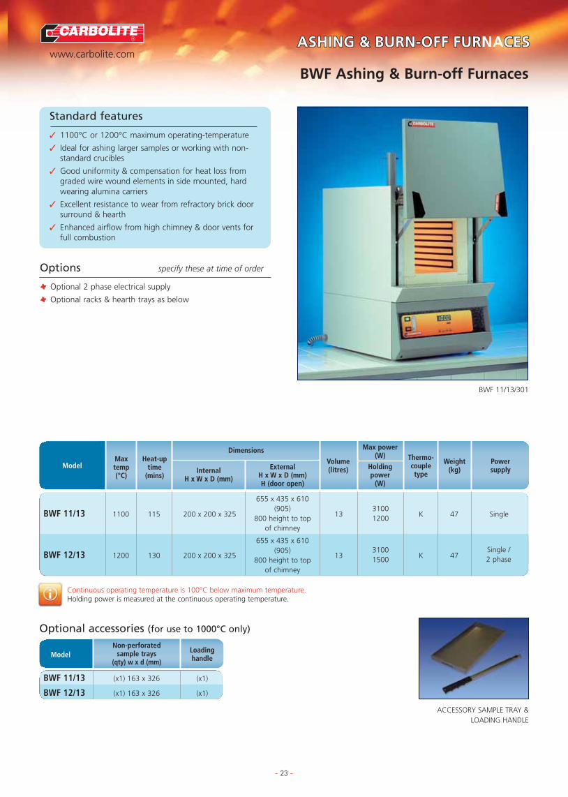
BWF Ashing & Burn-off Furnaces
- 23 -
Standard features
✓ 1100°C or 1200°C maximum operating-temperature
✓ Ideal for ashing larger samples or working with non-standard crucibles
✓ Good uniformity & compensation for heat loss fromgraded wire wound elements in side mounted, hardwearing alumina carriers
✓ Excellent resistance to wear from refractory brick doorsurround & hearth
✓ Enhanced airflow from high chimney & door vents forfull combustion
BWF 11/13/301
Options specify these at time of order
T Optional 2 phase electrical supply
T Optional racks & hearth trays as below
Continuous operating temperature is 100°C below maximum temperature.Holding power is measured at the continuous operating temperature.
Optional accessories (for use to 1000°C only)
Non-perforatedLoading
Model sample trayshandle(qty) w x d (mm)
BWF 11/13 (x1) 163 x 326 (x1)
BWF 12/13 (x1) 163 x 326 (x1)
BWF 11/13 1100 115 200 x 200 x 325 133100
K 47 Single 1200
BWF 12/13 1200 130 200 x 200 x 325 133100
K 471500
655 x 435 x 610(905)
800 height to top of chimney
655 x 435 x 610(905)
800 height to top of chimney
Single /2 phase
ModelMaxtemp(°C)
Heat-uptime
(mins)
Dimensions
InternalH x W x D (mm)
ExternalH x W x D (mm)H (door open)
Volume(litres)
Powersupply
Weight(kg)
Thermo-coupletype
Max power(W)
Holdingpower
(W)
ACCESSORY SAMPLE TRAY &LOADING HANDLE

TUBE FURTUBE FURNACESCESTUBE FURNACES
TUBE FURNACE OPTIONS
APPLICATION SPECIFIC FURNACES
FURNACE OPTIONS & EXTRAS
CHAMBER FURNACES
ASHING & BURN-OFF FURNACES
BESPOKE FURNACES
CUPELLATION FURNACES
Split Tube
� Both vertical and horizontally configured furnaces areavailable with the furnace body split and hinged along itslength.
� This enables easy access where worktubes are to be changedbetween jobs or where the furnace is to be wrapped aroundthe sample for example in tensile test rigs.
Application Specific & Bespoke DesignsRotary reactor, elevator tube and high vacuum tube furnaces arejust some of the standard variations of tube furnace availablefrom Carbolite. Many other bespoke modifications can beprovided offering alternative temperature ranges, dimensions,physical configurations, sample handling and functionality suchas rotating tubes. Simply contact Carbolite or your localdistributor for a quotation.
Temperature
� It is recommended to allow at least 100°C extra heatingrange above the desired working temperature.
� The chart below indicates the standard models available andtheir maximum operating temperatures from 900°C to1800°C.
� Different heating technologies are utilised to achieve eachgiven temperature range.
Size & Worktubes
� Some furnaces, most often those with wire wound elements,are supplied with an integral worktube, usually because theresistance wire element is wound directly onto the worktube.
� For some tube furnaces an accessory worktube is essential.
� An accessory worktube may be preferred either because ofits material properties or to protect (where there is one) theelement bearing worktube.
� See the ‘Tube Furnace Options’ section for advice onselecting the correct worktube.
Single or Three Zone
� Tube furnaces provide a high level of uniformity.
� For improved uniformity accessory end plugs or radiationshields should be purchased, especially for tube diameters > 25mm id.
� The length of the central uniform zone can be furtherincreased by adding heated zones at the ends in the form ofa three-zone furnace design.
Modified Atmosphere or Vacuum
� Tube furnaces are ideal when the sample must be heated inan inert atmosphere or a vacuum.
� A combination of end seals protected by thermal radiationshields should be considered. A longer worktube to isrequired to accommodate these.
Horizontal or Vertical
� Most Carbolite tube furnaces are available in horizontal andvertical configurations.
� When used vertically, end seals are strongly recommended tominimise the effects of convection currents through theworktube.
� In vertical configurations the furnace body is separate fromthe control module and attached by a 2 metre conduit.
Selection of a Tube Furnace
Factors for Selecting a Tube Furnace� Tube furnaces are frequently the most economical way to heat a small sample.
� Rapid temperature changes are possible by simply using a push-rod to move the sample along the lengthof the tube (although care must be taken not to cause thermal shock to the tube or sample boat).
� Additionally the work tube makes controlling the temperature uniformity and atmosphere around thespecimen much easier.
700
800°C
900°C
1000°C
1100°C
1200°C
1300°C
1400°C
1500°C
1600°C
1700°C
1800°C
WIRE WOUND
Single Single Single Three Single Three Single Single Single
SILICON CARBIDE MOLYBDENUM DISILICIDE
Element Type
Max
Tem
pera
ture
MTF*HTR (Rotary Reactor)
CTF*GHA12
HST GVA
VST
GHC362
HVTVacuum
STFTZFTZF
CTF17TZF
VST
CTFTZFPVT
HorizontalVertical* With integral worktube or Split tube design
Zones >
- 24 -

R
www.carbolite.comTUBE FURNACESCESTUBE FURNACES
TUBE FURNACE OPTIONS
APPLICATION SPECIFIC FURNACES
FURNACE OPTIONS & EXTRAS
CHAMBER FURNACES
ASHING & BURN-OFF FURNACES
BESPOKE FURNACES
CUPELLATION FURNACES
MTF Wire Wound Single Zone Tube Furnaces
- 25 -
Standard features
✓ 1000°C or 1200°C maximum operating temperature
✓ 15mm, 25mm or 38mm heated tube inner diameters
✓ 130mm, 250mm, 400mm or 850mm heated tube length
✓ Integral wirewound worktube
✓ Control module, with furnace mounted directly on top
✓ Carbolite 301 controller, with single ramp to set-point facility
✓ Delayed start / process timer function as standard
✓ Horizontal tube configuration
MTF 10/15/130
MTF 12/38/250
Options specify these at time of order
T Over-temperature protection (recommended to protectvaluable contents & for unattended operation)
T Non-permeable inner worktube to contain modifiedatmosphere
T Impervious inner worktubes to protect against chemicalattack or damage from thermal shock
T Insulation plugs & radiation shields to prevent heat loss &improve uniformity (recommended for vertical use)
T Gas injection & vacuum compatible tube end seal assemblies
Stand Options
Continuous operating temperature is 100°C below maximum temperature.Holding power is measured at the continuous operating temperature.*Uniform temperature lengths are measured with end plugs fitted.
MTF 10/15/130 1000 5 15 130265 x 150 x 175
30400
K 3 Single phase150 100
MTF 10/25/130 1000 10 25 130265 x 150 x 175
45400
K 3 Single phase150 100
MTF 12/25/250 1200 15 25 250375 x 370 x 375
60700
N 10 Single phase300 200
MTF 12/38/250 1200 25 38 250375 x 450 x 375
901000
N 15 Single phase300 300
MTF 12/25/400 1200 30 25 400430 x 370 x 375
1001000
N 10 Single phase450 200
MTF 12/38/400 1200 25 38 400430 x 450 x 375
1301500
N 15 Single phase450 300
MTF 12/38/850 1200 – 38 850430 x 900 x 375
600 2800 N – Single phase900
ModelMaxtemp(°C)
Heat-uptime
(mins)
Fixed tubeinner
diameter(mm)
Dimensions
Heatedtube
length(mm)
ExternalH x W x D (mm)
Furnace body length(mm)
*Uniformlength±5°C(mm)
Power supplyWeight(kg)
Thermo-coupletype
Maxpower
(W)
Holdingpower
(W)
Blanked Base L-stand: Vertical Use Horizontal Use Separated Controls (No Stand)
Starting with the compactMTF/9 through to the 850mmlong MTF 12/38 850, thesetube furnaces can be used byplacing samples directly intothe heated (wire wound)worktube or optionalaccessory worktubes can beused to protect the elementor work with modifiedatmospheres.
Wall Bracket

R
www.carbolite.comTUBE FURNACESCESTUBE FURNACES
TUBE FURNACE OPTIONS
APPLICATION SPECIFIC FURNACES
FURNACE OPTIONS & EXTRAS
CHAMBER FURNACES
ASHING & BURN-OFF FURNACES
BESPOKE FURNACES
CUPELLATION FURNACES
CTF Wire Wound Single Zone Tube Furnaces
- 26 -
Standard features
✓ 1200°C maximum operating temperature
✓ 65mm, 75mm or 100mm worktube inner diameters
✓ 550mm, 700mm or 900mm heated tube length
✓ Integral wirewound worktube
✓ Carbolite 301, PIP controller with digital set & display
✓ Delayed start / process timer function as standard
✓ Horizontal tube configuration
✓ Horizontal configuration with furnace located on top ofcontroller base
CTF 12/65/550
Options specify these at time of order
T Alternative ‘blank-base’ or ‘separated-base’ configurations
T Optionally configured for 2 phase electrical supply
T Non-permeable inner worktube to contain modifiedatmosphere
T Range of impervious inner worktubes to protect againstchemical attack or damage from thermal shock
T Insulation plugs & radiation shields to prevent heat loss &improve uniformity
T Gas injection & vacuum compatible tube end seal assemblies
T Over-temperature protection (recommended to protectvaluable contents & for unattended operation)
T 8 or 20 segment programmer
T RS232 communications & graphical recorders
Stand Options
Provides the advantages of a larger diameter and longerworktube than the MTF range, with the option of addingaccessory worktubes in order to use modified atmospheres or toprotect the wire wound element tube.
Continuous operating temperature is 100°C below maximum temperature.*Uniform temperature lengths are measured with end plugs fitted.** To ensure tube end temperatures that are compatible with sealing assemblies, worktubes extending beyond thestandard length are required when working with modified atmosphere. Radiation shields may also be required.
CTF 12/65/550 1200 45 65 550525 x 625 x 360
230 2000 N 25Single phase
600 or 2 phase
CTF 12/75/700 1200 45 75 700525 x 775 x 360
265 3000 N 28Single phase
750 or 2 phase
CTF 12/100/900 1200 90 100 900525 x 975 x 360
640 4500 N 35Single phase
950 or 2 phase
ModelMaxtemp(°C)
Heat-uptime
(mins)
Fixed tubeinner
diameter(mm)
Dimensions
Heatedtube
length
ExternalH x W x D (mm)
Furnace body length(mm)
*Uniformlength±5°C(mm)
Power supplyWeight(kg)
Thermo-coupletype
Maxpower
(W)
Blanked Base L-stand: Vertical Use Horizontal Use Wall Bracket Separated Controls (No Stand)
R
www.carbolite.comTUBE FURNACESCESTUBE FURNACES
TUBE FURNACE OPTIONS
APPLICATION SPECIFIC FURNACES
FURNACE OPTIONS & EXTRAS
CHAMBER FURNACES
ASHING & BURN-OFF FURNACES
BESPOKE FURNACES
CUPELLATION FURNACES
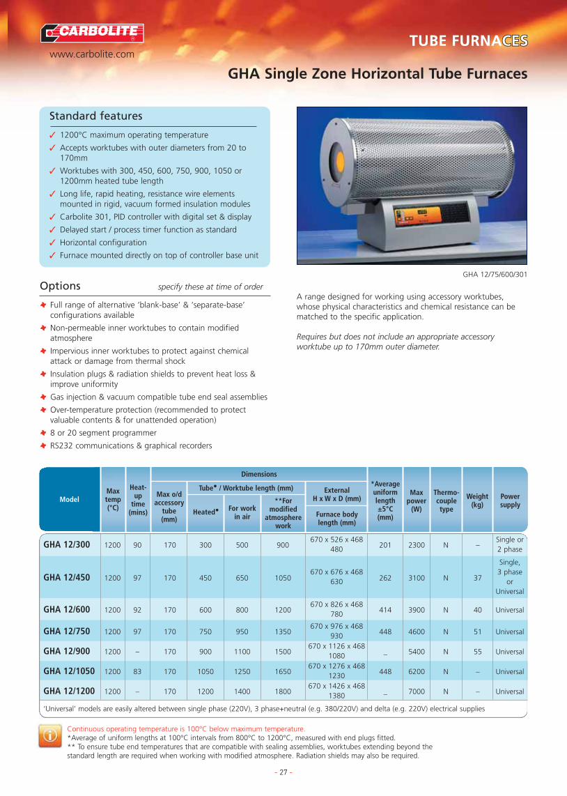
GHA Single Zone Horizontal Tube Furnaces
- 27 -
Standard features
✓ 1200°C maximum operating temperature
✓ Accepts worktubes with outer diameters from 20 to170mm
✓ Worktubes with 300, 450, 600, 750, 900, 1050 or1200mm heated tube length
✓ Long life, rapid heating, resistance wire elementsmounted in rigid, vacuum formed insulation modules
✓ Carbolite 301, PID controller with digital set & display
✓ Delayed start / process timer function as standard
✓ Horizontal configuration
✓ Furnace mounted directly on top of controller base unit
GHA 12/75/600/301
Options specify these at time of order
T Full range of alternative ‘blank-base’ & ‘separate-base’configurations available
T Non-permeable inner worktubes to contain modifiedatmosphere
T Impervious inner worktubes to protect against chemicalattack or damage from thermal shock
T Insulation plugs & radiation shields to prevent heat loss &improve uniformity
T Gas injection & vacuum compatible tube end seal assemblies
T Over-temperature protection (recommended to protectvaluable contents & for unattended operation)
T 8 or 20 segment programmer
T RS232 communications & graphical recorders
A range designed for working using accessory worktubes,whose physical characteristics and chemical resistance can bematched to the specific application.
Requires but does not include an appropriate accessoryworktube up to 170mm outer diameter.
Continuous operating temperature is 100°C below maximum temperature.*Average of uniform lengths at 100°C intervals from 800°C to 1200°C, measured with end plugs fitted.** To ensure tube end temperatures that are compatible with sealing assemblies, worktubes extending beyond thestandard length are required when working with modified atmosphere. Radiation shields may also be required.
ModelMaxtemp(°C)
Heat-up
time(mins)
Max o/daccessory
tube(mm)
Dimensions
Tube• / Worktube length (mm)
Heated• For workin air
ExternalH x W x D (mm)
Furnace bodylength (mm)
*Averageuniformlength±5°C(mm)
**Formodified
atmospherework
Powersupply
Weight(kg)
Thermo-coupletype
Maxpower
(W)
GHA 12/300 1200 90 170 300 500 900670 x 526 x 468
201 2300 N –Single or
480 2 phase
Single,670 x 676 x 468 3 phase
GHA 12/450 1200 97 170 450 650 1050 630 262 3100 N 37 orUniversal
GHA 12/600 1200 92 170 600 800 1200670 x 826 x 468
414 3900 N 40 Universal780
GHA 12/750 1200 97 170 750 950 1350670 x 976 x 468
448 4600 N 51 Universal930
GHA 12/900 1200 – 170 900 1100 1500670 x 1126 x 468
_ 5400 N 55 Universal1080
GHA 12/1050 1200 83 170 1050 1250 1650670 x 1276 x 468
448 6200 N – Universal1230
GHA 12/1200 1200 – 170 1200 1400 1800670 x 1426 x 468
_ 7000 N – Universal1380
‘Universal’ models are easily altered between single phase (220V), 3 phase+neutral (e.g. 380/220V) and delta (e.g. 220V) electrical supplies
R
www.carbolite.comTUBE FURNACESCESTUBE FURNACES
TUBE FURNACE OPTIONS
APPLICATION SPECIFIC FURNACES
FURNACE OPTIONS & EXTRAS
CHAMBER FURNACES
ASHING & BURN-OFF FURNACES
BESPOKE FURNACES
CUPELLATION FURNACES
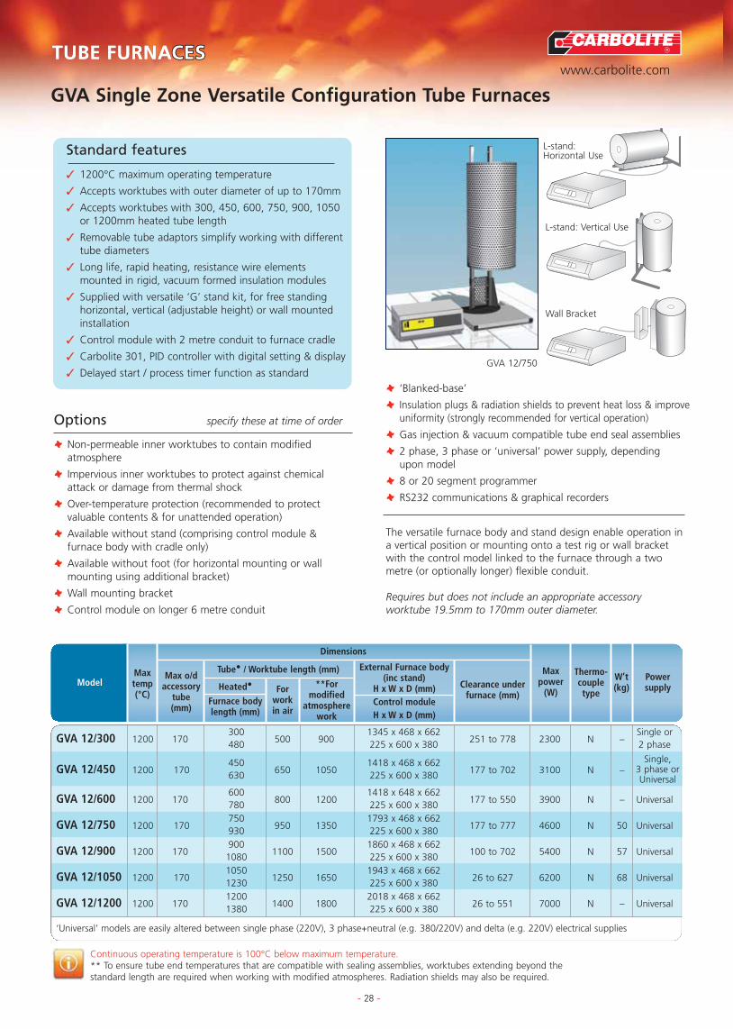
GVA Single Zone Versatile Configuration Tube Furnaces
- 28 -
Standard features
✓ 1200°C maximum operating temperature
✓ Accepts worktubes with outer diameter of up to 170mm
✓ Accepts worktubes with 300, 450, 600, 750, 900, 1050or 1200mm heated tube length
✓ Removable tube adaptors simplify working with differenttube diameters
✓ Long life, rapid heating, resistance wire elementsmounted in rigid, vacuum formed insulation modules
✓ Supplied with versatile ‘G’ stand kit, for free standinghorizontal, vertical (adjustable height) or wall mountedinstallation
✓ Control module with 2 metre conduit to furnace cradle
✓ Carbolite 301, PID controller with digital setting & display
✓ Delayed start / process timer function as standardGVA 12/750
The versatile furnace body and stand design enable operation ina vertical position or mounting onto a test rig or wall bracketwith the control model linked to the furnace through a twometre (or optionally longer) flexible conduit.
Requires but does not include an appropriate accessoryworktube 19.5mm to 170mm outer diameter.
Continuous operating temperature is 100°C below maximum temperature.** To ensure tube end temperatures that are compatible with sealing assemblies, worktubes extending beyond thestandard length are required when working with modified atmospheres. Radiation shields may also be required.
GVA 12/300 1200 170300
500 9001345 x 468 x 662
251 to 778 2300 N –Single or
480 225 x 600 x 380 2 phase
GVA 12/450 1200 170450
650 10501418 x 468 x 662
177 to 702 3100 N –630 225 x 600 x 380
GVA 12/600 1200 170600
800 12001418 x 648 x 662
177 to 550 3900 N – Universal780 225 x 600 x 380
GVA 12/750 1200 170750
950 13501793 x 468 x 662
177 to 777 4600 N 50 Universal930 225 x 600 x 380
GVA 12/900 1200 170900
1100 15001860 x 468 x 662
100 to 702 5400 N 57 Universal1080 225 x 600 x 380
GVA 12/1050 1200 1701050
1250 16501943 x 468 x 662
26 to 627 6200 N 68 Universal1230 225 x 600 x 380
GVA 12/1200 1200 1701200
1400 18002018 x 468 x 662
26 to 551 7000 N – Universal1380 225 x 600 x 380
‘Universal’ models are easily altered between single phase (220V), 3 phase+neutral (e.g. 380/220V) and delta (e.g. 220V) electrical supplies
Options specify these at time of order
T Non-permeable inner worktubes to contain modifiedatmosphere
T Impervious inner worktubes to protect against chemicalattack or damage from thermal shock
T Over-temperature protection (recommended to protectvaluable contents & for unattended operation)
T Available without stand (comprising control module &furnace body with cradle only)
T Available without foot (for horizontal mounting or wallmounting using additional bracket)
T Wall mounting bracket
T Control module on longer 6 metre conduit
Single, 3 phase orUniversal
ModelMaxtemp(°C)
Max o/daccessory
tube(mm)
External Furnace body(inc stand)
H x W x D (mm)Control module H x W x D (mm)
Clearance underfurnace (mm)
Powersupply
W’t(kg)
Thermo-coupletype
Maxpower
(W)
Dimensions
Tube• / Worktube length (mm)
Heated•
Furnace bodylength (mm)
Forworkin air
**Formodified
atmospherework
T ‘Blanked-base’
T Insulation plugs & radiation shields to prevent heat loss & improveuniformity (strongly recommended for vertical operation)
T Gas injection & vacuum compatible tube end seal assemblies
T 2 phase, 3 phase or ‘universal’ power supply, depending upon model
T 8 or 20 segment programmer
T RS232 communications & graphical recorders
L-stand: Vertical Use
L-stand: Horizontal Use
Wall Bracket

R
www.carbolite.comTUBE FURNACESCESTUBE FURNACES
TUBE FURNACE OPTIONS
APPLICATION SPECIFIC FURNACES
FURNACE OPTIONS & EXTRAS
CHAMBER FURNACES
ASHING & BURN-OFF FURNACES
BESPOKE FURNACES
CUPELLATION FURNACES
GHC Wire Embedded Three Zone Tube Furnaces
- 29 -
Standard features
✓ 1200°C maximum operating temperature
✓ Excellent uniformity results from the heated lengthdivided into 3 zones each with its own controller &thermocouple
✓ Power to the end zones is automatically adjusted tocompensate for heat loss, even without end plugs fitted
✓ Provides a longer uniform zone than that which can beachieved in a single zone tube furnace
✓ Heated tube lengths of 450, 600,750,900, 1050, or 1380m
✓ Accepts accessory worktubes with outer diameter up to170mm
✓ All three zones are controlled to the same set-point
✓ Horizontal configuration with furnace mounted ontocontrol module
✓ PID controller with single ramp to setpoint & process timer.
GHC 12/1200/3216P1 with over-temp
Options specify these at time of order
T End zones of either 150mm or 300mm long
T Insulation plugs & radiation shields to prevent heat loss &improve uniformity
T Gas injection & vacuum compatible tube end, sealassemblies
T 8 & 20 segment programmable controllers
T RS232 communications & graphical recorders
T ‘Retransmission of Setpoint’ control configuration tofacilitate programmed cooling
T Alternative furnace sizes can be supplied upon request
Three zone control provides a considerably longer uniformtemperature zone than is possible with single zone furnaces.However if a programmed controlled cooling ramp is requiredthen specify the ‘Retransmission of Setpoint’ control option atthe time of ordering.
Requires but does not include an appropriate accessoryworktube up to 170mm outer diameter.
Continuous operating temperature is 100°C below maximum temperature.Holding power is measured at the continuous operating temperature.Uniform length measured with end plugs fitted.
GHC 12/450 1200 98 170 450 750 1050672 x 676 x 468
3003100
N 6.5630 1500
GHC 12/600 1200 64 170 600 900 1200672 x 827 x 468
4403900
N 40 Universal780 1800
GHC 12/750 1200 74 170 750 1050 1350672 x 976 x 468
5004600
N 40 Universal930 2200
GHC 12/900 1200 79 170 900 1200 1500672 x 1126 x 468
6405400
N 51 Universal1080 2800
GHC 12/1050 1200 100 170 1050 1350 1650672 x 1276 x 468
8806200
N 55 Universal1230 2800
GHC 12/1200 1200 – 170 1200 1500 1800672 x 1426 x 468
–7000
N – Universal1380 3100
‘Universal’ models are easily altered between single phase (220V), 3 phase+neutral (e.g. 380/220V) and delta (e.g. 220V) electrical supplies
Singlephase orUniversal
ModelMaxtemp(°C)
Heat-up
time(mins)
Max o/daccessory
tube(mm)
ExternalH x W x D (mm)
Furnace body length(mm)
*Averageuniformlength±5°C(mm)
Powersupply
W’t(kg)
Thermo-coupletype
Dimensions
Tube• / Worktube length (mm)
Heated• For workin air
**Formodified
atmospherework
Maxpower
(W)
Holdingpower
(W)

R
www.carbolite.comTUBE FURNACESCESTUBE FURNACES
TUBE FURNACE OPTIONS
APPLICATION SPECIFIC FURNACES
FURNACE OPTIONS & EXTRAS
CHAMBER FURNACES
ASHING & BURN-OFF FURNACES
BESPOKE FURNACES
CUPELLATION FURNACES
GVC Wire Embedded Versatile Configuration Three Zone Tube Furnaces
- 30 -
Standard features
✓ 1200°C maximum operating temperature
✓ Excellent uniformity results from the heated length’sdivision into 3 zones each with its own controller &thermocouple
✓ Power to the end zones is automatically adjusted tocompensate for heat loss
✓ Provides a longer uniform zone than can be achieved in a single zone tube furnace
✓ Heated lengths of 450, 600, 750, 900, 1050, or 1380mm
✓ Accepts accessory work tubes with maximum outerdiameter of 170mm
✓ All three zones are controlled to the same set-point
✓ Vertical configuration with separate control module
✓ PID controller with single ramp to setpoint & process timer.GVC 12/750
Options specify these at time of order
T Impervious inner worktubes to protect against chemicalattack or damage from thermal shock
T Over-temperature protection (recommended to protectvaluable contents & for unattended operation)
T Available without stand (comprising control module &furnace body with cradle)
T Available without foot (for horizontal mounting or wallmounting using additional bracket)
T Wall mounting bracket
T Control module on longer 6 metre conduit
T ‘Blank base’ mounting option
T Gas injection & vacuum compatible tube end seal assemblies
T Insulation plugs & radiation shields are stronglyrecommended to prevent heat loss & improve uniformity(and are essential for vertical operation)
T 3 phase or ‘universal’ power supply, depending upon model
T 8 or 20 segment programmer
T ‘Retransmission of Setpoint’ control configuration to facilitateprogrammed cooling
T RS232 communications & graphical recorders
T Alternative furnace sizes can be supplied upon request
Providing the benefits of a three zone tube furnace in the formof an extended uniform zone together with versatile furnacemounting options and a separate control module linked througha 2 meter flexible conduit.
Requires but does not include an appropriate accessoryworktube with maximum 170mm outer diameter.
Continuous operating temperature is 100°C below maximum temperature.Holding power is measured at the continuous operating temperature.Uniform length measured with end plugs fitted.
GVC 12/450 1200 75 170450
750 1050 177 to 702 3003100
N630 1500
GVC 12/600 1200 80 170600
900 1200 177 to 550 4403900
N780 1800
GVC 12/750 1200 92 170750
1050 1350 177 to 777 5004600
N 50930 2200
GVC 12/900 1200 111 170900
1200 1500 100 to 702 6405400
N 571080 2800
GVC 12/1050 1200 122 1701050
1350 1650 26 to 627 8806200
N 681230 2800
GVC 12/1200 1200 81 1701200
1500 1800 26 to 551 –7000
N –1380 3100
‘Universal’ models are easily altered between single phase (220V), 3 phase+neutral (e.g. 380/220V) and delta (e.g. 220V) electrical supplies
1418 x 468 x 662225 x 600 x 380
1418 x 468 x 662225 x 600 x 380
1793 x 468 x 662225 x 600 x 380
1860 x 468 x 662225 x 600 x 380
1943 x 468 x 662225 x 600 x 380
2018 x 468 x 662225 x 600 x 380
Single, 3 phase orUniversal
Singlephase orUniveralSingle
phase orUniveralSingle
phase orUniveralSingle
phase orUniveralSingle
phase orUniveral
ExternalFurnace
H x W x D (mm)
Control moduleH x W x D (mm)
ModelMaxtemp(°C)
Heat-up
time(mins)
Maxo/d
access-orytube(mm)
*Averageuniformlength±5°C(mm)
Powersupply
W’t(kg)
Thermo-coupletype
Dimensions
Tube• / Worktube length (mm)
Heated•
Furnacebody
length (mm)
Forworkin air
**Formodified
atmospherework
Clearanceunder
furnace H (mm)
Maxpower
(W)
Holdingpower
(W)

R
www.carbolite.comTUBE FURNACESCESTUBE FURNACES
TUBE FURNACE OPTIONS
APPLICATION SPECIFIC FURNACES
FURNACE OPTIONS & EXTRAS
CHAMBER FURNACES
ASHING & BURN-OFF FURNACES
BESPOKE FURNACES
CUPELLATION FURNACES
HST Horizontal Single Zone Split Tube Furnaces
- 31 -
Standard features
✓ 1200°C maximum operating temperature
✓ Accepts worktubes with outer diameters up to 110mm
✓ Heated tube lengths of 200, 300, 400, 600, 900mm
✓ Furnace splits into two halves to accommodate reactorvessels, large workpieces or samples fixed into a test rig
✓ Long life, rapid heating, resistance wire elementsmounted in rigid, half cylindrical vacuum formedinsulation modules
✓ Control module with 2 metre conduit to furnace
✓ Carbolite 301 controller, with single ramp to set-point facility
✓ Delayed start / process timer function as standard
HST 12/70/600
Options specify these at time of order
T Non-permeable inner worktubes and end seal assemblies formodified atmosphere
T Impervious inner worktubes to protect against chemicalattack or damage from thermal shock
T Over-temperature protection (recommended to protectvaluable contents & for unattended operation)
T Available with ‘L’ stand kit for vertical or horizontal use
T Wall mounting bracket
T Control module on longer 6 metre conduit
T Insulation plugs & radiation shields to prevent heat loss &improve uniformity
T 2 phase, 3 phase or ‘universal’ power supply, dependingupon model
T 8 or 20 segment programmer
T RS232 communications & graphical recorders
Requires but does not include an appropriate accessoryworktube 19.5mm to 110mm outer diameter.Please specify worktube diameter when ordering split tubefurnaces.
Continuous operating temperature is 100°C below maximum temperature.*Average of uniform lengths at 100°C intervals from 800°C to 1200°C, measured with end plugs fitted.** To ensure tube end temperatures that are compatible with sealing assemblies, worktubes extended beyond thestandard length are required when working with modified atmospheres. Radiation shields may also be required.
HST 12/200 1200 45 110200
350 650350 x 325 x 410
100 1000 N 26Single or
350 225 x 600 x 380 2 phase
HST 12/300 1200 45 110300
450 750350 x 425 x 410
150 1500 N 28450 225 x 600 x 380
HST 12/400 1200 45 110400
550 850350 x 525 x 410
200 2000 N 32 Universal550 225 x 600 x 380
HST 12/600 1200 45 110600
750 1050350 x 725 x 410
300 3000 N 38 Universal750 225 x 600 x 380
HST 12/900 1200 45 110900
1050 1350350 x 1025 x 410
450 4500 N 60 Universal1050 225 x 600 x 380
‘Universal’ models are easily altered between single phase (220V), 3 phase+neutral (e.g. 380/220V) and delta (e.g. 220V) electrical supplies
Single, 3 phase
orUniversal
ModelMaxtemp(°C)
Heat-up
time(mins)
Max o/daccessory
tube(mm)
External Furnace (inc stand)
H x W x D (mm)Control module H x W x D (mm)
*Averageuniformlength±5°C(mm)
Powersupply
W’t(kg)
Thermo-coupletype
Maxpower
(W)
Dimensions
Tube• / Worktube length (mm)
Heated•
Furnace bodylength (mm)
For workin air
**Formodified
atmospherework

R
www.carbolite.comTUBE FURNACESCESTUBE FURNACES
TUBE FURNACE OPTIONS
APPLICATION SPECIFIC FURNACES
FURNACE OPTIONS & EXTRAS
CHAMBER FURNACES
ASHING & BURN-OFF FURNACES
BESPOKE FURNACES
CUPELLATION FURNACES
VST Vertical Single Zone Split Tube Furnaces
- 32 -
Standard features
✓ 1200°C Maximum operating temperature
✓ Accepts worktubes with outer diameters up to 110mm
✓ Heated lengths of 200, 300, 400, 600, 900mm
✓ Furnace hinges into two halves to accommodate reactorvessels, large workpieces or samples fixed into a test rig
✓ Long life, rapid heating resistance wire elementsmounted in rigid, half cylindrical vacuum formedinsulation modules
✓ Supplied in ‘near-hinge’ configuration complete withstand
✓ Control module with 2 metre conduit to furnace cradle
✓ Carbolite 301 controller, with single ramp to set-point facility
✓ Delayed start / process timer function as standardVST 12/600/3508P1 (near hinge)
Options specify these at time of order
T Insulation plugs & radiation shields to prevent heat loss &improve uniformity
T ‘Far-hinge’ configuration providing wider opening of furnacebody
T Non-permeable inner worktubes to contain modifiedatmosphere
T Impervious inner worktubes to protect against chemicalattack or damage from thermal shock
T Over-temperature protection (recommended to protectvaluable contents & for unattended operation)
T Control module on longer 6 metre conduit
T Gas injection & vacuum compatible tube end seal assemblies
T 3 phase or ‘universal’ power supply, depending upon model
T 8 or 20 segment programmer
T RS232 communications & graphical recorders
Continuous operating temperature is 100°C below maximum temperature.Holding power is measured at the continuous operating temperature.*Average of uniform length measured with end plugs fitted.** To ensure tube end temperatures that are compatible with sealing assemblies, worktubes extending beyond thestandard length are required when working with modified atmospheres. Radiation shields may also be required.
VST 12/200 1200 45 110200
500 800300 x 350 x 350 1000
N 24 Single 350 225 x 600 x 380 800
VST 12/300 1200 45 110300
600 900400 x 350 x 350
1500 N 25 Single450 225 x 600 x 380
VST 12/400 1200 45 110400
700 1000500 x 350 x 350 2000
N 26 Single550 225 x 600 x 380 900
VST 12/600 1200 45 110600
900 1200700 x 350 x 350 3000
N 32750 225 x 600 x 380 1100
VST 12/900 1200 45 110900
1200 15001000 x 350 x 350
4500 N 441050 225 x 600 x 380
‘Universal’ models are easily altered between single phase (220V), 3 phase+neutral (e.g. 380/220V) and delta (e.g. 220V) electrical supplies
Single, 3 phase orUniversal
Single, 3 phase orUniversal
ModelMaxtemp(°C)
Max o/daccessory
tube(mm)
Heat-up
time(mins)
Heated•
Furnace bodylength (mm)
For workin air
ExternalFurnace (inc stand)
H x W x D (mm)Control module H x W x D (mm)
**Formodified
atmospherework
Powersupply
W’t(kg)
Thermo-coupletype
Maxpower
(W)
Holdingpower
(W)
Dimensions
Tube• / Worktube length (mm)
Optionalfar-hinge
Standardnear-hinge
The free standing vertical design is ideal for wrap aroundheating applications such as extension test rigs or verticalreaction tubes. The ‘far hinge’ option opens wider for greaterflexibility in application.
Usually requires but does not include an appropriate accessoryworktube 19.5mm to 110mm outer diameter.End plugs are strongly recommended when using vertical tubefurnaces.

R
www.carbolite.comTUBE FURNACESCESTUBE FURNACES
TUBE FURNACE OPTIONS
APPLICATION SPECIFIC FURNACES
FURNACE OPTIONS & EXTRAS
CHAMBER FURNACES
ASHING & BURN-OFF FURNACES
BESPOKE FURNACES
CUPELLATION FURNACES
- 33 -
Standard features
✓
TZF Wire Wound Horizontal Three Zone Tube Furnaces
Standard features
✓ 1200°C maximum operating temperatures
✓ Excellent uniformity results from division of the heatedlength into 3 equal zones each with its own controller & thermocouple.
✓ Provides a longer uniform zone than can be achieved insingle zone tube furnace
✓ Power to the end zones is automatically adjusted tocompensate for heat loss
✓ All three zones are controlled to the same set-point
✓ Heated lengths of 400, 550, 700 or 900mm
✓ Models accepting worktubes with outer diameters of38mm to 90mm
✓ Horizontally mounted on control module base
TZF 12/75/700/3216P1
Options specify these at time of order
T Shorter end zone option to provide extended uniformlength (optionally in 2 phase configuration)
T Insulation plugs & radiation shields to prevent heat loss &improve uniformity
T Gas injection & vacuum compatible worktube end sealassemblies
T Separate control module on 2 metre or 6 metre conduit
T ‘L’ style flexible stand option for vertical or independentmounting
T 8 or 20 segment programmer
T ‘Retransmission of Setpoint’ zone control configuration forprogrammed cooling
T RS232 communications & graphical recorders
T Alternative furnace sizes can be supplied upon request
Comprising an horizontal furnace body with three zone wirewound worktube element that is equipped as standard with‘Back to Back’ zone control. It can be used directly or withaccessory worktubes.
Continuous operating temperature is 100°C below maximum temperature.Holding power is measured at the continuous operating temperature.Uniform length measured with end plugs fitted.
TZF 12/38/400 1200 25 38 400 450430 x 450 x 375
3051175
N 32 Single450 700
TZF 12/65/550 1200 45 65 550 600525 x 625 x 360
3901817
N 38Single
600 600 3 phase
TZF 12/75/700 1200 45 90 700 750525 x 775 x 360
5402755
N 46Single
750 800 3 phase
TZF 12/100/900 1200 120 90 900 950525 x 975 x 360
7544150
N 54Single or
950 1000 Universal
‘Universal’ models are easily altered between single phase (220V), 3 phase+neutral (e.g. 380/220V) and delta (e.g. 220V) electrical supplies
ModelMaxtemp(°C)
Heat-uptime
(mins)
Max o/daccessory
tube(mm)
Dimensions
Heatedtube
length(mm)
ExternalH x W x D (mm)
Furnace bodylength (mm)
Overallfurnacelength(mm)
*Uniformlength±5°C(mm)
Powersupply
Weight(kg)
Thermo-coupletype
L-stand: Vertical UseL-stand: Horizontal Use
Maxpower
(W)
Holdingpower
(W)

Continuous operating temperature is 100°C below maximum temperature.Holding power is measured at the continuous operating temperature.
R
www.carbolite.comTUBE FURNACESCESTUBE FURNACES
TUBE FURNACE OPTIONS
APPLICATION SPECIFIC FURNACES
FURNACE OPTIONS & EXTRAS
CHAMBER FURNACES
ASHING & BURN-OFF FURNACES
BESPOKE FURNACES
CUPELLATION FURNACES
EVT Elevator Tube Furnaces
Standard features
✓ 1100°C Maximum operating temperature
✓ Integral 100mm inner diameter x 400mm long, plasmasprayed IAP worktube
✓ Furnace body rises and lowers on electrically driven slidemechanism
✓ Fixed position sample holder
✓ 20 segment programmable control as standard
✓ Over-temperature protection as standard
✓ Long life, rapid heating, 1100°C resistance wireelements mounted in rigid, vacuum formed insulationmodules
✓ Furnace body mounted on integral floor / bench stand.
✓ Stand alone control module with 2 metre conduit
EVT 11/100/400
Options specify these at time of order
T Inert gas purging system
T 3 phase power supply
T RS232 communications & graphical recordersDesigned specifically for applications where the test samplemust be disturbed as little as possible whilst being introducedinto the furnace. As an additional option the furnace can befitted with an inert gas purging system to supply cooling air orinert gas into the tube as preset intervals.
EVT 11/100/400 1100 100 400 400 4001200 x 800 x 600
R - Single900 x 600 x 500
ModelMaxtemp(°C)
Heat-uptime
(mins)
Max i/daccessory
tube(mm)
External Furnace(inc stand)
H x W x D (mm)Control moduleH x W x D (mm)
Powersupply
W’t(kg)
Thermo-coupletype
Maxpower
(W)
Holdingpower
(W)
Dimensions
Tube• / Worktube length (mm)
Heated• For workin air
**Formodified
atmospherework
- 34 -

R
www.carbolite.comTUBE FURNACESCESTUBE FURNACES
TUBE FURNACE OPTIONS
APPLICATION SPECIFIC FURNACES
FURNACE OPTIONS & EXTRAS
CHAMBER FURNACES
ASHING & BURN-OFF FURNACES
BESPOKE FURNACES
CUPELLATION FURNACES
HZS & TVS Wire Embedded Versatile Configuration Three Zone Split Tube Furnaces
- 35 -
Standard features
✓ 1200°C maximum operating temperature
✓ Accepts accessory worktubes with maximum outerdiameters up to 110mm
✓ Heated length of 600mm or 900mm
✓ Versatile horizontal (HZS) or vertical (TVS) configurationfurnaces with separate control module on 2 metre conduit
✓ Furnace splits into two halves to accommodate reactorvessels, large workpieces or samples fixed into a test rig
✓ Long life, rapid heating, resistance wire elementsmounted in rigid, half cylindrical vacuum formedinsulation modules
✓ Carbolite 301 controller, with single ramp to set-pointfacility with two back to back 2132 controllers
✓ Delayed start / process timer function as standard
TVS 12/600/3216P (near hinge)
Options specify these at time of order
T With end zones either 150mm long or with threeapproximately equal length zones
T Insulation plugs & radiation shields to prevent heat loss &improve uniformity (strongly recommended for vertical tubes)
T Non-permeable inner worktubes to contain modifiedatmosphere
T Impervious inner worktubes to protect against chemicalattack or damage from thermal shock
T Over-temperature protection (recommended to protectvaluable contents & for unattended operation)
T Available with ‘L’ stand kit for vertical and horizontal use
T Wall mounting bracket
T ‘Far-hinge’ configuration alternatives for the vertical TVSrange
T Control module on longer 6 metre conduit
T Gas injection & vacuum compatible tube end seal assemblies
T 3 phase or ‘universal’ power supply
T 8 or 20 segment programmer
T RS232 communications & graphical recorders
Ranges of horizontal (HZS) and vertical (TVS) three zone splittube furnaces heated using wire wound elements. These offerthe advantages of increased uniform heated length and afurnace body capable of versatile horizontal, vertical or ‘L’ standmounting.
Requires but does not include an appropriate accessoryworktube up to 110mm outer diameter.Please indicate worktube diameter at time of ordering.
Continuous operating temperature is 100°C below maximum temperature.Holding power is measured at the continuous operating temperature.Uniform length measured with end plugs fitted.
HZS 12/600 1200 45 110600
900 1200350 x 725 x 410
5003000
N 40750 225 x 600 x 380 –
HZS 12/900 1200 45 110900
1200 1500350 x 1050 x 410
7504500
N 651050 225 x 600 x 380 1100
TVS 12/600 1200 45 110600
600 750700 x 350 x 350
5003000
N 34750 225 x 600 x 380 –
TVS 12/900 1200 45 110900
1200 10501000 x 350 x 350
7504500
N 441050 225 x 600 x 380 –
‘Universal’ models are easily altered between single phase (220V), 3 phase+neutral (e.g. 380/220V) and delta (e.g. 220V) electrical supplies
3 phase orUniversal
3 phase orUniversal
3 phase orUniversal
3 phase orUniversal
ModelMaxtemp(°C)
Heat-up
time(mins)
Max o/daccessory
tube(mm)
External Furnace
H x W x D (mm)
Control moduleH x W x D (mm)
*Averageuniformlength±5°C(mm)
Powersupply
W’t(kg)
Thermo-coupletype
Maxpower
(W)
Holdingpower
(W)
Optionalfar-hinge
Standardnear-hinge
Dimensions
Tube• / Worktube length (mm)
Heated•
Furnacebody
length (mm)
Forworkin air
**Formodified
atmospherework

R
www.carbolite.comTUBE FURNACESCESTUBE FURNACES
TUBE FURNACE OPTIONS
APPLICATION SPECIFIC FURNACES
FURNACE OPTIONS & EXTRAS
CHAMBER FURNACES
ASHING & BURN-OFF FURNACES
BESPOKE FURNACES
CUPELLATION FURNACES
- 36 -
Standard features
✓
STF High Temperature Single Zone Tube Furnaces
Standard features
✓ 1500°C & 1600°C maximum operating temperatures
✓ Using worktubes of 60 or 90mm outer diameter
✓ Accepts worktubes with 180, 450 or 610mm heatedtube length
✓ Silicon carbide heating elements
✓ Horizontal configuration
✓ Carbolite 301 controller, with single ramp to set-point facility
✓ Delayed start / process timer function as standard
STF 15/180/301 (L STAND OPTION)
Options specify these at time of order
T Available with ‘L’ stand kit or wall bracket for vertical orhorizontal use
T Available in ‘Blank-stand’ or ‘Separate-stand’ configurations
T Non-permeable inner worktubes to contain modifiedatmosphere
T Impervious inner worktubes to protect against chemicalattack or damage from thermal shock
T Over-temperature protection (recommended to protectvaluable contents & for unattended operation)
T Insulation plugs & radiation shields to prevent heat loss &improve uniformity-recommended for vertical tubes
T Gas injection & vacuum compatible tube end, sealassemblies
T 3 Phase or ‘universal’ power supply, depending upon model
T 8 or 20 Segment programmer
T RS232 communications & graphical recorders
A range of tube furnaces offering the higher temperatures thatare available from silicon carbide heating elements, with theadditional option of a vertical ‘L’ stand and separate controller ifpreferred. The user must select an accessory worktube specificto their application.
Requires but does not include an appropriate accessoryworktube 19.5mm to either 60mm or 90mm outer diameter.
Blanked Base L-stand: Horizontal Use L-stand: Vertical Use Separated Controls (No Stand)
Wall Bracket Normal Construction(Horizontal)

Continuous operating temperature is 100°C below maximum temperature.Holding power is measured at the continuous operating temperature.Uniform length measured with end plugs fitted.** To ensure tube end temperatures that are compatible with sealing assemblies, worktubes extending beyond thestandard length are required when working with modified atmospheres. Radiation shields may also be required.
R
www.carbolite.comTUBE FURNACESCESTUBE FURNACES
TUBE FURNACE OPTIONS
APPLICATION SPECIFIC FURNACES
FURNACE OPTIONS & EXTRAS
CHAMBER FURNACES
ASHING & BURN-OFF FURNACES
BESPOKE FURNACES
CUPELLATION FURNACES
- 37 -
STF High Temperature Single Zone Tube Furnaces
ModelMaxtemp(°C)
Heat-uptime
(mins)
Maxo/d
access-ory
tube(mm)
Dimensions
Tube• / Worktube length (mm)
**Formodified
atmospherework
Heated•For
workin air
ExternalH x W x D (mm)
Furnace bodylength (mm)
Uni-form
length±5°C(mm)
W’t(kg)
T/Ctype
Maxpower
(W)
SupplyRequired
(W)
Power supplyrequired per phase
a1=12A, d1=24A
a1=39A, a2=19.5A,c3=25A
a1=32A, b1=44A,a2=19.5A, f3=19.5A
a3=34A
a1=23A
a1=47A, a2=24A,h3=21A,
a3=39A, g3=21A
a1=50A, a2=25A,h3=25A, i3=27A,d3=43A, e3=46A
STF 15/180 1500 60 180 600 900500 x 600 x 375
80 1500 R 29600
STF 15/450 1500 90 450 900 1200660 x 830 x 445
3505500
R 34900 3800
STF 15/610 1500 90 610 1200 1500660 x 1130 x 445
4006000
R 451200 4200
STF 16/180 1600 60 180 600 900500 x 600 x 375
802500
R 29600 ➝
STF 16/450 1600 90 450 900 1200660 x 830 x 445
3506000
R 40900 ➝
STF 16/610 1600 90 610 1200 1500660 x 1130 x 445
4007000
R 501200 ➝
Rate will
vary
with
state of
oxidation
and age
of
elements
a1=Single 200-240V, b1=Single 200-208V, d1=Single 110-120V, a2=380-415V 2 phase + N, a3=200-240V 3 phase delta, c3=Single 200-208V 3 phase + N, d3=200-220V 3 phase delta, e3=230-240V 3 phase delta, f3=Single 220-240V 3 phase +N, g3=380-415V 3 phase no N, h3=380-415V 3 phase + N, i3=400-415 3 phase + N
STF 15/610 with over-temp
Power Supplies for Silicon CarbideFurnacesThe characteristics of the control systems that areused with silicon carbide elements result inmaximum power supply requirements that are notas intuitively derived as those for furnaces usingother heating technologies. For this reason a moredetailed description of the maximum powersupply that is required per phase has beenincluded in the specification table.

R
www.carbolite.comTUBE FURNACESCESTUBE FURNACES
TUBE FURNACE OPTIONS
APPLICATION SPECIFIC FURNACES
FURNACE OPTIONS & EXTRAS
CHAMBER FURNACES
ASHING & BURN-OFF FURNACES
BESPOKE FURNACES
CUPELLATION FURNACES
VST Vertical Single Zone Split Tube Furnaces
- 38 -
Standard features
✓ 1700°C Maximum operating temperature
✓ Heated tube length of 250mm
✓ Three models for tubes with outer diameters up to32mm, 32 to 66mm and 66 to 90mm
✓ Furnace splits into two halves to accommodate reactorvessels, large workpieces or samples fixed into a test rig
✓ Molybdenum disilicide elements to 1700°C
✓ Supplied in ‘near-hinge’ configuration complete withstand
✓ Control module with 2m conduit to furnace cradle
✓ Carbolite 3216P1 controller with 16 paired segmentprogrammability
✓ Over-temperature protection, from secondary controller
VST 17/250
Options specify these at time of order
T Non permeable inner worktubes to contain modifiedatmosphere
T Impervious inner worktubes to protect against chemicalattack or damage from thermal shock
T Control module on longer 6m conduit
T Insulation plugs & radiation shields are stronglyrecommended for high temperature vertical tube furnacesto prevent heat loss & improve uniformity.
T Gas injection & vacuum compatible tube end seal assemblies
T 20 segment programmer
T RS232 Communications & graphical recorders
The free standing vertical design is ideal for wrap aroundheating applications such as extension test rigs or verticalreaction tubes. Two hinge designs (‘near hinge or ‘far-hinge’)provide a wider opening furnace body and hence even moreapplication flexibility.
Usually requires but does not include an appropriate accessoryworktube 32mm, 66mm or 90mm maximum outer diameter.
Continuous operating temperature is 100°C below maximum temperature.Holding power is measured at the continuous operating temperature.*Average of uniform length measured with end plugs fitted** To ensure tube end temperatures that are compatible with sealing assemblies, worktubes extending beyond thestandard length are required when working with modified atmospheres. Radiation shields may also be required.
ModelMaxtemp(°C)
Max o/daccessory
tube(mm)
Heat-up
time(mins) Heated• For work
in air
External Furnace (inc stand)
H x W x D (mm)
Control module H x W x D (mm)
**Formodified
atmospherework
Powersupply
Weight(kg)
Thermo-coupletype
Maxpower
(W)
Dimensions
Tube• / Worktube length (mm)
VST 17/250/32 1700 – 32 250 550 850865 x 600 x 705
4500 B 173Single
630 x 600 x 490 phase
VST 17/250/66 1700 – 66 250 550 850865 x 600 x 705
4500 B 173Single
630 x 600 x 490 phase
VST 17/250/90 1700 – 90 250 1050 15001560 x 750 x 890
4500 B –Single
630 x 600 x 490 phase
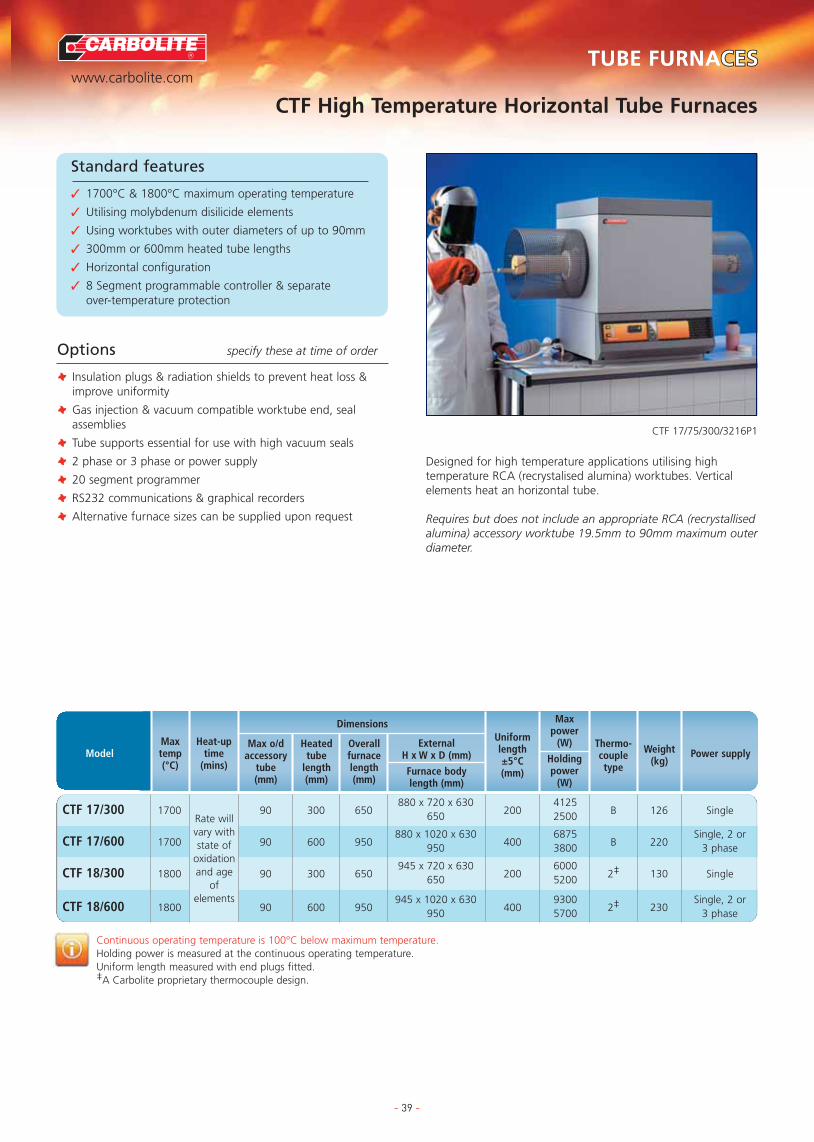
R
www.carbolite.comTUBE FURNACESCESTUBE FURNACES
TUBE FURNACE OPTIONS
APPLICATION SPECIFIC FURNACES
FURNACE OPTIONS & EXTRAS
CHAMBER FURNACES
ASHING & BURN-OFF FURNACES
BESPOKE FURNACES
CUPELLATION FURNACES
- 39 -
Standard features
✓
CTF High Temperature Horizontal Tube Furnaces
Standard features
✓ 1700°C & 1800°C maximum operating temperature
✓ Utilising molybdenum disilicide elements
✓ Using worktubes with outer diameters of up to 90mm
✓ 300mm or 600mm heated tube lengths
✓ Horizontal configuration
✓ 8 Segment programmable controller & separate over-temperature protection
CTF 17/75/300/3216P1
Options specify these at time of order
T Insulation plugs & radiation shields to prevent heat loss &improve uniformity
T Gas injection & vacuum compatible worktube end, sealassemblies
T Tube supports essential for use with high vacuum seals
T 2 phase or 3 phase or power supply
T 20 segment programmer
T RS232 communications & graphical recorders
T Alternative furnace sizes can be supplied upon request
Designed for high temperature applications utilising hightemperature RCA (recrystalised alumina) worktubes. Verticalelements heat an horizontal tube.
Requires but does not include an appropriate RCA (recrystallisedalumina) accessory worktube 19.5mm to 90mm maximum outerdiameter.
Continuous operating temperature is 100°C below maximum temperature.Holding power is measured at the continuous operating temperature.Uniform length measured with end plugs fitted.‡A Carbolite proprietary thermocouple design.
CTF 17/300 1700 90 300 650880 x 720 x 630
2004125
B 126 Single650 2500
CTF 17/600 1700 90 600 950880 x 1020 x 630
4006875
B 220Single, 2 or
950 3800 3 phase
CTF 18/300 1800 90 300 650945 x 720 x 630
2006000
2‡ 130 Single650 5200
CTF 18/600 1800 90 600 950945 x 1020 x 630
4009300
2‡ 230Single, 2 or
950 5700 3 phase
Rate willvary withstate of
oxidationand age
ofelements
ModelMaxtemp(°C)
Heat-uptime
(mins)
Max o/daccessory
tube(mm)
Dimensions
Heatedtube
length(mm)
ExternalH x W x D (mm)
Furnace bodylength (mm)
Uniformlength±5°C(mm)
Overallfurnacelength(mm)
Power supplyWeight(kg)
Thermo-coupletype
Maxpower
(W)
Holdingpower
(W)

R
www.carbolite.comTUBE FURNACESCESTUBE FURNACES
TUBE FURNACE OPTIONS
APPLICATION SPECIFIC FURNACES
FURNACE OPTIONS & EXTRAS
CHAMBER FURNACES
ASHING & BURN-OFF FURNACES
BESPOKE FURNACES
CUPELLATION FURNACES
- 40 -
Standard features
✓
PVT High Temperature Vertical Tube Furnaces
Standard features
✓ 1800°C maximum operating temperature
✓ Utilising lanthanum chromite elements (these generallyachieve slower heating rates than other elementmaterials)
✓ Using worktubes with maximum outer diameters of 60, 90, 115 or 140mm
✓ Heated lengths of 200mm or 350mm
✓ Vertical (only) configuration using the ‘L’ stand assembly
✓ Separate control module on 2 metre conduit
✓ 8 Segment programmable controller incorporating over-temperature protection
PVT 18/125/350 (with custom shortened stand)
Options specify these at time of order
T Insulation plugs & radiation shields to prevent heat loss &improve uniformity (strongly recommended for verticaltubes)
T Gas injection & vacuum compatible tube end, sealassemblies
T 20 segment programmer
T RS232 communications & graphical recorders
T Alternative furnace sizes can be supplied upon request For slower heating, high temperature applications requiring avertically orientated tube furnace body, which accepts RCA(recrystalised alumina) accessory worktubes.
Requires but does not include an appropriate RCA (recrystallisedalumina) accessory worktube 19.5mm to either 60mm, 90mm,115mm or 140mm outer diameter, depending on the model.
Note: Lanthanum chromite elements may give off smallamounts of chromium vapour in use, which can causecontamination or slight pink colouration when work is carriedout without the use of a worktube.
Continuous operating temperature is 100°C below maximum temperature.Holding power is measured at the continuous operating temperature.Uniform length measured with end plugs fitted.‡A Carbolite proprietary thermocouple design.
Rate willvary withstate of
oxidationand age
of elements
PVT 18/50/200 1800 60 200850 x 700 x 810
-5500
2‡ 2702 phase or
222 x 570 x 375 4000 3 phase
PVT 18/75/350 1800 90 3501000 x 700 x 810
-9000
2‡ 300 3 phase222 x 570 x 375 5000
PVT 18/100/350 1800 115 3501000 x 700 x 810
-6000
2‡ 400 3 phase222 x 570 x 375 5000
PVT 18/125/350 1800 140 3501000 x 700 x 810
-9300
2‡ 500 3 phase222 x 570 x 375 7000
ModelMaxtemp(°C)
Heat-uptime
(mins)
Max o/daccessory
tube(mm)
Dimensions
Heatedtube
length(mm)
ExternalFurnace
H x W x D (mm)
Control moduleH x W x D (mm)
Power supplyWeight(kg)
Thermo-coupletype
Maxpower
(W)
Holdingpower
(W)
Furnacebody
length(mm)

R
www.carbolite.comTUBE FURNACESCESTUBE FURNACES
TUBE FURNACE OPTIONS
APPLICATION SPECIFIC FURNACES
FURNACE OPTIONS & EXTRAS
CHAMBER FURNACES
ASHING & BURN-OFF FURNACES
BESPOKE FURNACES
CUPELLATION FURNACES
TZF High Temperature Three Zone Horizontal Tube Furnaces
- 41 -
Standard features
✓ 1800°C maximum operating temperature
✓ Accepts worktubes with outer diameters of up to 90mm
✓ Heated lengths of 600 or 610mm
✓ Includes end-zone controller using “back to back”control configuration
✓ Carbolite 301 controller with simple ramp to set pointsfacility (TZF 15 & TZF 16)
✓ 8 segment programmable temperature control (TZF 17 &TZF 18)
✓ Overtemperature protection (TZF 17 & TZF 18)
✓ Delayed start / process timer function as standard
TZF 15/610
Options specify these at time of order
T Non-permeable inner worktubes to contain modifiedatmosphere
T Impervious inner worktubes to protect against chemicalattack or damage from thermal shock
T Over-temperature protection (recommended to protectvaluable contents & for unattended operation) (TZF 15 & TZF 16)
T Insulation plugs & radiation shields to prevent heat loss &improve uniformity
T Control module with 2 metre conduit to furnace cradle
T Gas injection & vacuum compatible tube end seal assemblies
T 2 phase, 3 phase or ‘universal’ power supply, dependingupon model
T 20 segment programmer
T RS232 communications & graphical recorders
T ‘Retransmission of Setpoint’ control configuration tofacilitate programmed cooling
Range of silicon carbide & molybdenum disilicide heated threezone furnaces supplied with ‘Back to Back’ controls as standard.Where programmed cooling rates are required or the option ofvertical orientation is chosen then ‘Retransmission of Setpoint’control should requested at time of order.
Requires but does not include an appropriate accessoryworktube up to 90mm outer diameter.
Note: 1700°C or 1800°C furnaces have case configurationsimilar to the CTF series.
Continuous operating temperature is 100°C below maximum temperature.Uniform length measured with end plugs fitted.‡A Carbolite proprietary thermocouple design.
TZF 15/610 1500 75 90 610 900 1650 660 x 1130 x 4458000
R 444000
TZF 16/610 1600 – 90 610 900 1500 660 x 1130 x 4459150
R 1814500
TZF 17/600 1700 150 90 600 1200 1500 880 x 1020 x 6309000
B 2803800
TZF 18/600 1800 150 90 600 1200 1500 645 x 1020 x 630 9300 2‡ 280
ModelMaxtemp(°C)
Heat-uptime
(mins)External
H x W x D (mm)
Power supplyrequired per phase
W’t(kg)
T/Ctype
Maxpower
(W)
Holdingpower
(W)
Max o/daccessory
tube(mm)
Dimensions
Tube• / Worktube length (mm)
Heated• For workin air
**Formodified
atmospherework
a1=60A, h3=22A, e3=38A
c1=62A, h3=25A, e3=40A
a1=46A, b1=48A, h3=28A, e3=34A,
a1=40A, b3=30A, e3=28A, h3=24A
a1=Single 200-240V, b1=200-208V, c1= Single 220-240V, d3=200-220V 3 phase delta, e3=230-240V 3 phase delta, h3=380-415V 3 phase + N

R
www.carbolite.comTUBE FURNACESCESTUBE FURNACES
TUBE FURNACE OPTIONS
APPLICATION SPECIFIC FURNACES
FURNACE OPTIONS & EXTRAS
CHAMBER FURNACES
ASHING & BURN-OFF FURNACES
BESPOKE FURNACES
CUPELLATION FURNACES
HVTT High Vacuum Tube Furnaces
- 42 -
Standard features
✓ 1200°C & 1500°C maximum operating temperature
✓ Capable of 10-5 mbar vacuum in clean empty worktube.
✓ Complete with worktube with inner diameters of either50, 60, 80 or 75mm
✓ Worktube with heated lengths of 450mm, 550mm or 700mm
✓ Vacuum provided by two stage rotary sliding vane pump& turbo-molecular pump
✓ Manually operated roughing / backing baffle valve
✓ Pirani gauge low vacuum monitor
✓ Penning gauge high vacuum monitor
✓ Worktube connects to the vacuum system via 90°stainless steel radiused connection
✓ Access to the worktube is via removable stainless steelvacuum flange
✓ Radiation shields at both ends of worktube maintainuniformity without reducing pump speeds
✓ The vacuum system & all controls are mounted withinthe base unit
HVTT TURBO-MOLECULAR HIGH VACUUM TUBE FURNACE
Options specify these at time of order
T Overtemperature protection (recommended in all cases ofunattended operation or where valuable samples are to beprocessed)
T Vertical configurations also available
T A variety of gas backfill systems are available
T Additional safety systems for use with combustibleatmospheres
T Automatic & semi-automatic vacuum systems
A range of 5 standard units capable of high vacuum operationwhich also form a base from which bespoke customer designscan be developed in order to meet specific applicationrequirements.
Continuous operating temperature is 100°C below maximum temperature.Holding power is measured at the continuous operating temperature.
T Air or water cooled diffusion pump
T Oil-free pump options available
T Cooling water failure alarm
T Three zone control for improved uniformity
T Special vertical & custom build configurations
T 8 or 20 segment programmer
T RS232/RS484 communications & graphical recorders
HVTT 12/50/550 1200 50 550 1450 x 1700 x 6002000
N –1600
HVTT 12/60/700 1200 60 700 1450 x 1700 x 6003000
N –1800
HVTT 12/80/700 1200 80 700 1450 x 1700 x 6003500
N –2800
HVTT 15/50/450 1500 50 450 1565 x 1700 x 6005500
R –4800
HVTT 15/75/450 1500 75 450 1565 x 1700 x 6005500
R –4800
ModelMaxtemp(°C)
Worktubeinner
diameter(mm)
Dimensions
Heatedtube
length(mm)
ExternalFurnace
H x W x D (mm)
Power supplyrequired per phase
Weight(kg)
Thermo-coupletype
Max power(W)
Holdingpower
(W)
c1=14.5A
c1=18.5A
c1=21A
c1=45A, a2=26A
c1=45A, a2=26A
c1=220-240V, a2=380-415 2 phase + N

R
www.carbolite.comTUBE FURNACESCESTUBE FURNACES
TUBE FURNACE OPTIONS
APPLICATION SPECIFIC FURNACES
FURNACE OPTIONS & EXTRAS
CHAMBER FURNACES
ASHING & BURN-OFF FURNACES
BESPOKE FURNACES
CUPELLATION FURNACES
HTR Rotary Reactor Furnaces
- 43 -
Standard features
✓ 1100°C maximum operating temperature
✓ Developed in partnership with the Imperial College ofScience & Technology, London
✓ Digital PID temperature control
✓ Heating is provided by long life, rapid heating, resistancewire elements mounted in rigid, half cylindrical vacuumformed insulation modules
✓ The fluted internal surface of the reactor ensures goodmixing as the variable speed electric drive systemoscillates the reactor tube
✓ A positive break safety interlock switch cuts power tothe elements when the heating chamber is open
✓ Gas enters the reactor through a flexible silicon rubber tube
✓ A 30mm flow meter calibrated for nitrogen is provided
✓ A single seal gasket directs the reactor exhaust into aremovable stainless steel exhaust box from where a gasoutlet would enable piping to an extraction system
HTR 11/75
Options specify these at time of order
T Over-temperature protection (recommended in all cases ofunattended operation or where valuable samples are to beprocessed)
T Single or multiple flow meters calibrated for different gases
T 8 or 20 segment programmer
T RS232 communications & graphical recorders
These furnaces combine many of the advantages of fluidisedbed reactors with those of a rotary kiln. The sample can besimultaneously heated and agitated under a controlledatmosphere. This overcomes the long reaction times requiredwhen using conventional muffle furnaces or static tube under aflowing atmosphere.
Includes fused quartz reaction vessel.
Continuous operating temperature is 100°C below maximum temperature.Holding power is measured at the continuous operating temperature.
HTR 11/75 110011 75 x 100
1 to 8 315°480 x 1140 x 550 1500
K 40 Single15 50ml 800 x 1140 x 680 400
HTR 11/150 110021 150 x 200
1 to 8 315°540 x 1300 x 900 3000
K 95 Single15 700ml 950 x 1300 x 900 1000
ModelMaxtemp(°C)
Heat-uptime (mins)
Coolingtime with lid open(mins)
Reactionchamber
dimensions(mm)
& Capacity
Dimensions
Oscillationfrequencyper min
Rotation ineach
direction
ExternalH x W x D (mm)
Lid up
Lid down
Powersupply
Weight(kg)
Thermo-coupletype
Maxpower
Holdingpower
(W)
Applications
✓ Applications in lab scale calcination of materials
✓ Calcining arsenical gold ores under neutral atmospheres toremove sulphur & arsenic
✓ Analysis of sulphur ores in metallurgical slags
✓ Operation as a low temperature rotary reactor furnace toremove organic solvent from oxide pigment materials
✓ Roasting sulphide ores to convert them to oxides
✓ Determination of silica content in rice husks
✓ Low temperature calcination of of limestone & dolomite
✓ Calcining colliery spoils at up to 1000°C
Reaction Tube
Oscillation of 1 to 8 times per minute
315°

R
www.carbolite.comTUBE FURNACESCESTUBE FURNACES
TUBE FURNACE OPTIONS
APPLICATION SPECIFIC FURNACES
FURNACE OPTIONS & EXTRAS
CHAMBER FURNACES
ASHING & BURN-OFF FURNACES
BESPOKE FURNACES
CUPELLATION FURNACES
SPTF Rotating Tube Furnaces
Large and fully bespoke designs are available up to pilot plant scale (see below)
- 44 -
Standard features
✓ 1200°C, 1500°C or 1600°C maximum operatingtemperature
✓ Based upon standard CTF12/75700, CTF12/100/900, STF 15/610 or STF 16/610 standard furnaces
✓ Provides laboratory scale simulation of industrial rotarycalcining kilns
✓ Powders are heated & agitated within the tube ensuringthat all of the sample becomes exposed to theatmosphere
✓ A 0 to 5° tilting mechanism controls throughput
Options specify these at time of order
T Plain tubes are available in ceramic, quartz or heat resistantmetal alloys as well as shaped vessels in quartz & metalequipped with agitation blades.
T Variable speed drives from 1 to 10 rpm
T Vibratory feed mechanisms
T Atmosphere control systems
ROTATING TILTING SPLIT TUBE FURNACE(guards removed for illustrative purposes)

One of the natural outcomes arising from customersapproaching Carbolite to modify standard furnaces or tomanufacture completely bespoke products to meet specificapplication needs, is the growth of a range of furnaces that aredesigned for distinctive applications. Applications can rangefrom calcining powders at a laboratory scale through toassaying precious metals for marking under the InternationalHallmarking Convention.
More frequently furnaces are designed to enable testing to aspecific ISO, BS/EN or ASTM standard method.
As with all the other furnaces in the Carbolite range, thestandard design is frequently available with a wide range ofalternative voltage configurations and controller options. Thefurnaces described on these pages can also provide the basis forcustomised designs.
TUBE FURNACES
TUBE FURNACE OPTIONS
APPLICATION SPECIFIC FURNACESATION SPECIFIC FURNACESAPPLICATION SPECIFIC FURNACES
FURNACE OPTIONS & EXTRAS
CHAMBER FURNACES
ASHING & BURN-OFF FURNACES
BESPOKE FURNACES
CUPELLATION FURNACES
- 45 -
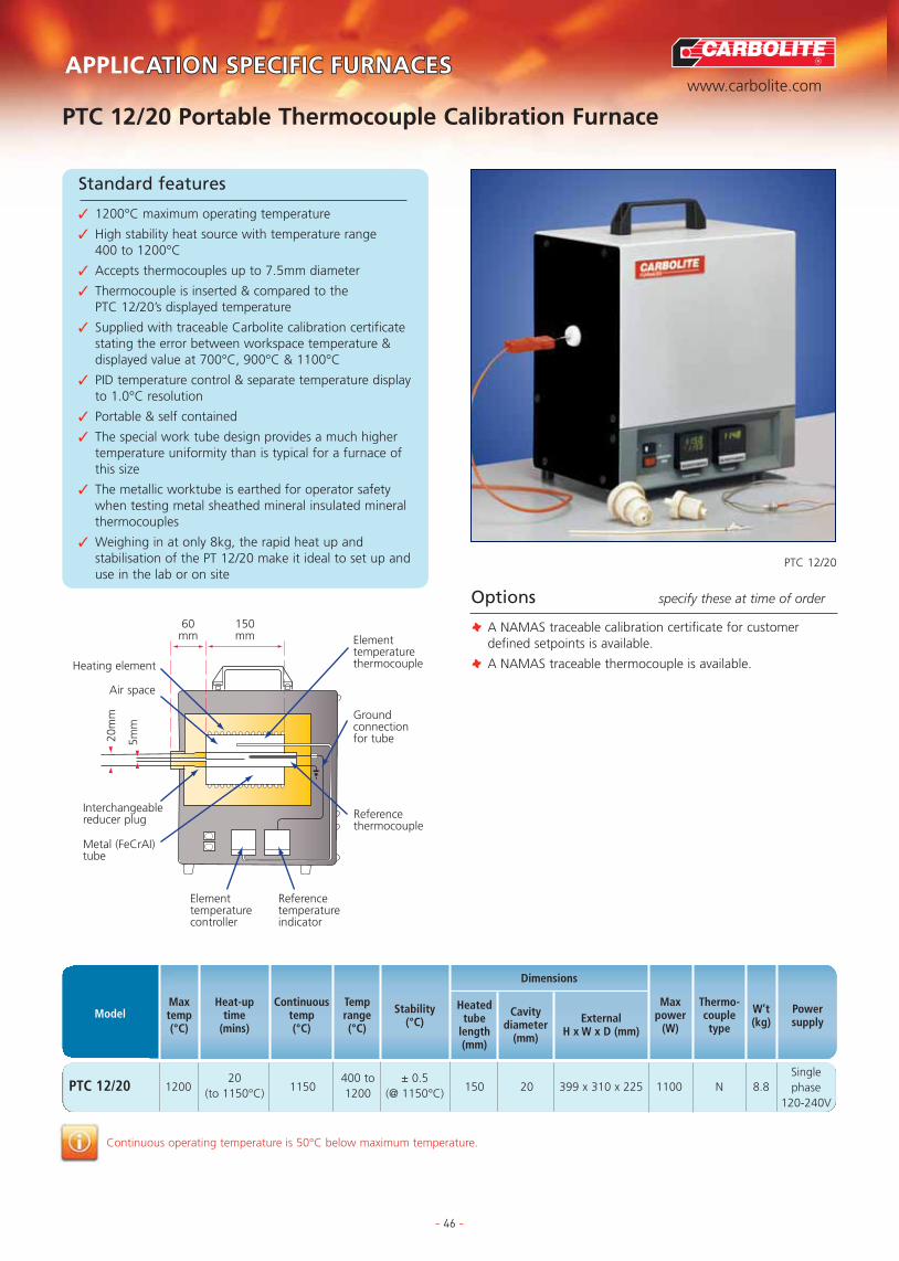
R
www.carbolite.com
TUBE FURNACES
TUBE FURNACE OPTIONS
APPLICATION SPECIFIC FURNACESATION SPECIFIC FURNACESAPPLICATION SPECIFIC FURNACES
FURNACE OPTIONS & EXTRAS
CHAMBER FURNACES
ASHING & BURN-OFF FURNACES
BESPOKE FURNACES
CUPELLATION FURNACES
PTC 12/20 Portable Thermocouple Calibration Furnace
- 46 -
Standard features
✓ 1200°C maximum operating temperature
✓ High stability heat source with temperature range 400 to 1200°C
✓ Accepts thermocouples up to 7.5mm diameter
✓ Thermocouple is inserted & compared to the PTC 12/20’s displayed temperature
✓ Supplied with traceable Carbolite calibration certificatestating the error between workspace temperature &displayed value at 700°C, 900°C & 1100°C
✓ PID temperature control & separate temperature displayto 1.0°C resolution
✓ Portable & self contained
✓ The special work tube design provides a much highertemperature uniformity than is typical for a furnace ofthis size
✓ The metallic worktube is earthed for operator safetywhen testing metal sheathed mineral insulated mineralthermocouples
✓ Weighing in at only 8kg, the rapid heat up andstabilisation of the PT 12/20 make it ideal to set up anduse in the lab or on site
PTC 12/20
Options specify these at time of order
T A NAMAS traceable calibration certificate for customerdefined setpoints is available.
T A NAMAS traceable thermocouple is available.
Continuous operating temperature is 50°C below maximum temperature.
PTC 12/20 120020
1150400 to ± 0.5
150 20 399 x 310 x 225 1100 N 8.8(to 1150°C) 1200 (@ 1150°C)
Singlephase
120-240V
ModelMaxtemp(°C)
Heat-uptime
(mins)
Continuoustemp(°C)
Dimensions
Temprange(°C)
Stability(°C) External
H x W x D (mm)
Cavitydiameter
(mm)
Heatedtube
length(mm)
Powersupply
W’t(kg)
Thermo-coupletype
Maxpower
(W)
Referencetemperatureindicator
Elementtemperaturecontroller
Metal (FeCrAI)tube
Interchangeablereducer plug
Air space
Heating element
Elementtemperaturethermocouple
Groundconnectionfor tube
Referencethermocouple
60 150mm mm
20m
m
5mm

R
www.carbolite.com
TUBE FURNACES
TUBE FURNACE OPTIONS
APPLICATION SPECIFIC FURNACESATION SPECIFIC FURNACESAPPLICATION SPECIFIC FURNACES
FURNACE OPTIONS & EXTRAS
CHAMBER FURNACES
ASHING & BURN-OFF FURNACES
BESPOKE FURNACES
CUPELLATION FURNACES
AGD Acid Gas Determinator Furnaces
- 47 -
Standard features
✓ 1200°C maximum operating temperature
✓ Designed for combustion testing of electrical cable to BS EN 50267-1:1999
✓ Cable samples are heated within the worktubes at acontrolled rate of rise, whilst a small flow of air is passedover the samples & analysed (using separate apparatus)for acidity
✓ Four IAP tube design gives increased working capacity
✓ Fast resistance wire heating at <40 mins to 800°C(better than 20°C/min to 1000°C)
✓ Digital temperature controller providing precise setting & repeatability
✓ Highly stable temperature control – the temperature atthe centre of each tube will be within ±5°C over alength of 300mm**
✓ Low thermal mass insulation
✓ Power control by solid state relay, incorporating zerovoltage switching
AGD 12/4
Options specify these at time of order
T Fused silica inner tubes 41mm inner diameter x 45mm outerdiameter x1000mm (NOTE fused silica tends to devitrifywhen used above 1000°C)
T Programmable control to provide automatic cooling afterthe timed hold at maximum that is required by the standard
* Heat up time is measured 100°C maximum temperature with empty tubes.** With no gas flow – BSEN 50267-1 1999 requires ±17.5°C with a ‘small’ gas flow.IAP is Impervious Aluminous Porcelain.Continuous operating temperature is 100°C below maximum temperature.
AGD 12/4 1200400 to
<40 4 800 x 50 x 60 640 x 800 x 480 1100 N 8.81200
Single Phase220-240V50/60Hz
20A
ModelMaxtemp(°C)
Temp range(°C)
Heat-uptime
(mins)to
1000°C
Dimensions
ExternalH x W x D (mm)
No.worktubes
Worktubedimensions
L x inner Ø x
outer Ø (mm)
Powersupply
Weight(kg)
Thermo-coupletype
Maxpower
(W)
Airflow over sample
553mm heated length
800mm
125
1000mm
To analysis system
50mm IDIAP tubes
Optional Silico (Quartz) tubes
Powerful, lightweight vacuum-formedheating elements give fast heating and cooling
Sample
Controlthermocouple
92mm
480mm
640m
m
416m
m
92m
m

R
www.carbolite.com
TUBE FURNACES
TUBE FURNACE OPTIONS
APPLICATION SPECIFIC FURNACESATION SPECIFIC FURNACESAPPLICATION SPECIFIC FURNACES
FURNACE OPTIONS & EXTRAS
CHAMBER FURNACES
ASHING & BURN-OFF FURNACES
BESPOKE FURNACES
CUPELLATION FURNACES
CF Series Cupellation Furnaces for the Assay of Precious Metals
- 48 -
Standard features
✓ 1200°C maximum operating temperature
✓ Models with a maximum charge capacity of 15, 24, 50or 60 number 8 cupels
✓ Alternatively 24, 32, 72, or 90 number 6 cupels
✓ Designed for testing using the cupellation method toISO11426:1999 the standard test method used by theUnited Kingdom Assay Office, a reference quantitativeassay method laid down by the International HallmarkConvention
✓ The CF furnaces are internationally renowned for theirclose temperature uniformity and hazardous fume control*
✓ Airflow controlled by an adjustable valve, is preheatedbefore entering the work chamber
✓ Silicon carbide elements mounted above & below thechamber provide even heating of cupels, have goodresistance to thermal shock & offer extended workinglife at high temperatures
✓ Fumes are extracted through insulated exhaust duct,with removable chamber below chimney to collectcondensed lead
✓ Up & away counterbalanced vertically opening doorcomplete with observation hole
✓ Silicon carbide lined roof & hearth resist the corrosivefumes emitted during the cupellation process
✓ Includes 7 day, 24 hour timeswitch
CF SERIES
Options specify these at time of order
T Modified configurations are available to fit existing fumeextraction systems
Note: The furnace should be positioned beneath an efficientfume extraction system preferably fitted with a proprietary leadfilter* Fumes are extracted through an insertable exhaust duct and
removable container below the chimney.
CF 15 1200 125 x 220 x 350 15 9000Pt/Pt 13% Rh
Type R
CF 24 1200 205 x 255 x 460 24 13000Pt/Pt 13% Rh
306Type R
CF 50 1200 230 x 350 x 540 50 20000Pt/Pt 13% Rh
Type R
CF 60 1200 250 x 400 x 650 60 31000Pt/Pt 13% Rh
Type R
ModelMaxtemp(°C)
Dimensions
InternalH x W x D (mm)
ExternalH x W x D (mm)
Volume(litres)
Power supplyrequired per phase
Weight(kg)
Thermo-coupletype
Maxpower
(W)
1059 x 950 x 950(bench mounted)225 x 600 x 380
(Separate control module)
2110x1050x1070(floor standing)
2100x1150x1100(floor standing)
2100x1200x1200(floor standing)
a1=68A, h3=23A, a3=40A
a1=87A, h3=28A, a3=50Aj3=30A
h3=45A, e3=78A, k3=45A
h3=62A a3=107A. k3=62A
a1=Single 200-240V, a3=200-240V 3 phase delta, e3=230-240V 3 phase delta, h3=380-415V 3 phase + N, j3=440-480V 3 phase no N, k3=440-480V 3 phase + N
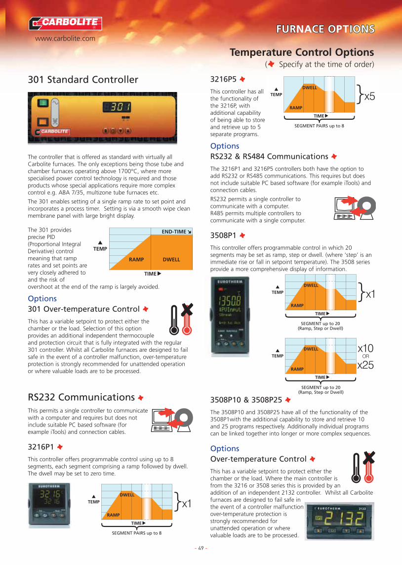
R
www.carbolite.com
TUBE FURNACES
FURTUBE FURNACE OCE OPTIONSIONS
APPLICATION SPECIFIC FURNACES
FURNACE OPTIONS
FURNACE OPTIONS & EXTRAS
CHAMBER FURNACES
ASHING & BURN-OFF FURNACES
BESPOKE FURNACES
CUPELLATION FURNACES
Temperature Control Options(T Specify at the time of order)
- 49 -
301 Standard Controller
The controller that is offered as standard with virtually allCarbolite furnaces. The only exceptions being those tube andchamber furnaces operating above 1700°C, where morespecialised power control technology is required and thoseproducts whose special applications require more complexcontrol e.g. ABA 7/35, multizone tube furnaces etc.
The 301 enables setting of a single ramp rate to set point andincorporates a process timer. Setting is via a smooth wipe cleanmembrane panel with large bright display.
The 301 providesprecise PID(Proportional IntegralDerivative) controlmeaning that ramprates and set points arevery closely adhered toand the risk ofovershoot at the end of the ramp is largely avoided.
Options301 Over-temperature Control TThis has a variable setpoint to protect either thechamber or the load. Selection of this optionprovides an additional independent thermocoupleand protection circuit that is fully integrated with the regular301 controller. Whilst all Carbolite furnaces are designed to failsafe in the event of a controller malfunction, over-temperatureprotection is strongly recommended for unattended operationor where valuable loads are to be processed.
RS232 Communications T
This permits a single controller to communicatewith a computer and requires but does notinclude suitable PC based software (forexample iTools) and connection cables.
3216P1 TThis controller offers programmable control using up to 8segments, each segment comprising a ramp followed by dwell.The dwell may be set to zero time.
3216P5 TThis controller has allthe functionality ofthe 3216P, withadditional capabilityof being able to storeand retrieve up to 5separate programs.
OptionsRS232 & RS484 Communications TThe 3216P1 and 3216P5 controllers both have the option toadd RS232 or RS485 communications. This requires but doesnot include suitable PC based software (for example iTools) andconnection cables.
RS232 permits a single controller tocommunicate with a computer.R485 permits multiple controllers tocommunicate with a single computer.
3508P1 TThis controller offers programmable control in which 20segments may be set as ramp, step or dwell. (where ‘step’ is animmediate rise or fall in setpoint temperature). The 3508 seriesprovide a more comprehensive display of information.
3508P10 & 3508P25 TThe 3508P10 and 3508P25 have all of the functionality of the3508P1with the additional capability to store and retrieve 10and 25 programs respectively. Additionally individual programscan be linked together into longer or more complex sequences.
OptionsOver-temperature Control TThis has a variable setpoint to protect either thechamber or the load. Where the main controller isfrom the 3216 or 3508 series this is provided by anaddition of an independent 2132 controller. Whilst all Carbolitefurnaces are designed to fail safe inthe event of a controller malfunctionover-temperature protection isstrongly recommended forunattended operation or wherevaluable loads are to be processed.
END-TIME
TIME
▲TEMP
▲
RAMP DWELL
TIME
▲
▲TEMP
RAMP
SEGMENT PAIRS up to 8
DWELL }x1
SEGMENT PAIRS up to 8
}x5TIME
▲
▲TEMP
RAMP
DWELL
TIME
▲
▲TEMP
RAMP
SEGMENT up to 20(Ramp, Step or Dwell)
DWELL }x1
TIME
▲
▲TEMP
RAMP
SEGMENT up to 20(Ramp, Step or Dwell)
DWELL x10OR
x25

R
www.carbolite.com
TUBE FURNACES
FURTUBE FURNACE OCE OPTIONSIONS
APPLICATION SPECIFIC FURNACES
FURNACE OPTIONS
FURNACE OPTIONS & EXTRAS
CHAMBER FURNACES
ASHING & BURN-OFF FURNACES
BESPOKE FURNACES
CUPELLATION FURNACES
Cascade Control TThis should be considered for evenmore precision and ability tocounteract many of theperformance effects that result fromplacing different loads into thechamber. In particular faster heatingof loads which have high thermalcapacity is possible. A standard controller operates by sensingthe temperature close to the elements. In cascade control theprimary controller’s operation is modified by a secondnonprogrammable 3216 controller, which is used to sense thetemperature of the load. It is essential that the primarycontroller is one of the 3508 series
Three Zone Control TThis usually has the function in triple zone tube furnaces ofextending the length of the uniform heated zone.
Back-to-back ControlThis configuration is supplied asstand for all Carbolite three zonetube furnaces. Normally a master301 controller operates with two2132 end-zone controllers.
Independent TThis configuration is available as ano-charge option for three zonetube furnaces and comprises threeindependent controllers with either301 or 2132 end zone controllerseach with independentthermocouples in their respective zones.
Setpoint Retransmission TThis optional configuration should be selected for three zone tubefurnaces where programmed cooling using a 3216 or 3508controller is required, in order that the slave end zones adhere to the cooling profile.
Three Zone Cascade Control TAs in single zone furnaces, cascade control allows faster heatingof the furnace load and more precise control of the loadtemperature. A 3508 controller is required, the end zones arecontrolled using (non-programmable) 3216CC controllers.
Eurotherm nanodac™ Recorder & PID ControllerTThe nanodac™ combines PIDtemperature control with a 50MB datarecording and archiving capability. Datafrom up to 4 channels can be recorded
into the on-board flash memory or can be output in CSV fileformat to a removable USB device (up to 8GB) or by FTP filetransfer onto a specific Ethernet linked network server.
Data can be viewed as horizontal or vertical trends, bar-graphsor as numeric data.
Control is via a bright clear 3.5” TFT colour display, with a wideangle of resolution and 4 simple navigation buttons. Anadditional 14 ‘virtual channels’ provide the capability to performmaths functions on the data (e.g. add, subtract, multiply, divide,channel or group; average, maximum, minimum) as well assalve communications, totalise and counter functions. .
Chart Recorders & DAQs (Data Aquisition Devices) T
This is just a small selection of the options that are available forrecording data from Carbolite furnaces. If you require adviceplease contact Carbolite for further information.
NOTE: Please confirm with Carbolite whether the chart recordercan be fitted within the standard furnace case, in someinstances it may require mounting in a separate case.
4102 Series 100mm WideCompact Strip ChartRecorder TThe 4102 series are compact andeconomical 100mm strip chartrecorders, providing recording for upto 4 (continuous pen) or 6 (multi-point) process variables.
4103 Series 100mm WideStrip Chart Recorder TThe 4103 is a high specification,100mm strip chart recorder, providingcontinuous recording for up to 6process variables. Information such aschannel descriptor, alarm set pointand scale information can be viewedon a high resolution VFD display.
- 50 -
Temperature Control Options(T Specify at the time of order)
10, 30, 60, 120or
5, 20, 60, 120or
20, 30, 60, 120or
30, 60, 120,300 or
Softwareselectable
LoadElements
Cascade
Back-to-back
Independent
Setpoint retransmission
User AccuracyModel Channels prog- To paper Speed Annotation
(pens) rammable (%) mm/hr T T
4102C 1 ✘Extra
option
4102C 2 ✘Extra
option
4102M 6 ✘0.25 Standard
4103C 1 ✓ Standard
4103C 2 ✓ Standard
4103M 6 ✓ Standard

R
www.carbolite.com
TUBE FURNACES
FURTUBE FURNACE OCE OPTIONSIONS
APPLICATION SPECIFIC FURNACES
FURNACE OPTIONS
FURNACE OPTIONS & EXTRAS
CHAMBER FURNACES
ASHING & BURN-OFF FURNACES
BESPOKE FURNACES
CUPELLATION FURNACES
6100 & 6180 Series Digital Data Acquisition,Recording & Display TA series of digital data acquisitionrecorders which can function asstand-alone paperless recorders orwith more advanced models can beintegrated in to computer networks.All have the capability to archive datevia USB flah memory devices or onto anetworked server using Ethernet FTPor Modbus TCP (although the 6100Eis Slave configuration only)
6100 series data recorders have a 5/14” TFT touch screeninterface whilst the 6180 series data recorders have a 12.1” TFTtouch screen interface.
The 6100XIO and 6180XIO datarecorders record digital data and somust be used with controllers that areequipped with digitalcommunications. This overcomespotential issues from the attenuationof analogue signals over distance.
The 6180AeroDAQ is a recorderconfiguration that has been optimisedfor NADCAP – AMS 2750D applications and includesthermocouple monitoring functionality for this purpose.Always confirm with Carbolite that your preferred data recordercan be accommodated within the furnace structure, alternativea stand-alone case may be required.
The following software options are available for usewith the 6100A, 6100XIO and 6180 series data recordersfor the 6100 Series (these options are not compatiblewith the 6100E model)BatchingGrouping Screen Builder Bridge 0 software a
iTools SoftwareA versatile suite of softwarethat allows Carbolite furnacesthat have been fitted withappropriate digitalcommunications hardware tobe set-up, recorded andmonitored from a PC. Thesupplied license is for a singlePC to communicate with one furnace using RS232 or withmany furnaces using RS485.NOTE: The 301 controller is not compatible with RS485communications.
- 51 -
Temperature Control Options(T Specify at the time of order)
Calibration CertificatesA number of calibration options can be suppliedeach of which is available with either a factorycertificate of calibration or a certificate from aUKAS accredited laboratory and hence traceableto a UK National Standard.
Factory issued certificate for the thermocouple onlycalibrated at 3 temperature points T
UKAS traceable certificate for the thermocouple onlycalibrated at 3 temperature points T
Factory issued certificate for the temperature controller(or temperature display) 3 point calibration TAt 3 points of our choosing.
UKAS traceable certificate for the temperature controller(or temperature display) 3 point calibration TAt 3 points of our choosing.
Factory issued certificate for the specific individualcombination of thermocouple & temperature controller(or temperature display) 3 point calibration T
UKAS traceable certificate for the specific individualcombination of thermocouple & temperature controller(or temperature display) 3 point calibration T
For Advice and Specifications toComply with NADCAP (AMS 2750D) for Heat TreatmentApplicationsPlease contact Carbolite for advice on this or any otherstandards compliance issues.
Model
nanodac
6100E
6100A
6180A
6100XIO
6180XIO
6180AeroDAQ
Function
PID control& record
record analogue
input
record analogue
input
recordanalogue
input
recorddigitalcommsinput
recorddigitalcommsinput
recordanalogue
input
On-boardMemory forhistory (Mb)
50
8
32 or 96
32 or 96
32
32
32
USBports
USB
1
up to3
up to3
1
3
DisplayScreen
5.5”TFT &
softwareallocated
keys
5.5” VGAtouchscreen
12.1” VGAtouchscreen
12.1”XGA
touchcreen
5.5” VGAtouchscreen
12.1” XGAtouchscreen
12.1” XGAtouchscreen
Channels
4
3/6**optional
6
12
18
48
6
SerialPorts
0
0
up to2
up to2
2
2
2

R
www.carbolite.com
TUBE FURNACES
TUBE FURNACE OCE OPTIONSIONS
APPLICATION SPECIFIC FURNACES
TUBE FURNACE OPTIONS
FURNACE OPTIONS & EXTRAS
CHAMBER FURNACES
ASHING & BURN-OFF FURNACES
BESPOKE FURNACES
CUPELLATION FURNACES
MTF 9, 10 or 12 Series CTF or TZF 12 Series
Up to 900, 1000, 1200°C15 ~ 38mm ID
130 ~ 400mm heated length
ID Inner DiameterOD Outer Diameter
130 ~ 400mm heated length
Up to 1200°C65 ~ 105mm ID
550 ~ 900mm heated length
Furnace includingStandard worktube+ Extended worktube type D (one size below heated ID & length+ 300mm)+ Insulation end plugs type D(ref 51-50-1)+ Gas tight end seals (ref 41-37-1)
FurnaceStandard worktube+ Extended worktube type D (one size below heated ID & length +300mm or 250mm for CTF 12/100/900)+ Insulation end plugs type D (ref 41-50-11 or 41-50-12)+ Gas tight end seals (ref 41-37-1 or 41-37-2)
Furnace includingStandard worktube+ Extended worktube type D (one size below heated ID & length+ 300mm)+ Radiation end shields type D(ref 41-51-1)+ Vacuum end seals (ref 41-37-5 + 51-39-1)
FurnaceStandard worktube+ Extended worktube type D (one size below heated ID & length+ 600mm)+ Radiation end shields(ref 41-51-1 or 41-51-2)+ Vacuum end seals (ref 41-37-5 or 41-37-6 + 51-39-2 + 51-39-3)
Furnace includingstandard worktube+ Insulation end plugs type C (ref 51-50-1 or 51-50-2)
Furnace + Standard worktube + Insulation end plugs type C (ref 51-50-1 or 51-50-2)
Suitable for aninert gasatmosphere (or vacuum to10
-3bar using
NW flange seals)
Suitable forheating in air
Suitable forvacuum to10
-5bar)
Tube Furnace Options & Accessories for Heating
Please note that additional components are required for vertical configurationsThermocouple entry glands are available for both gas tight and vacuum end sealsTube supports 49-64-1 recommended for extended length tubes
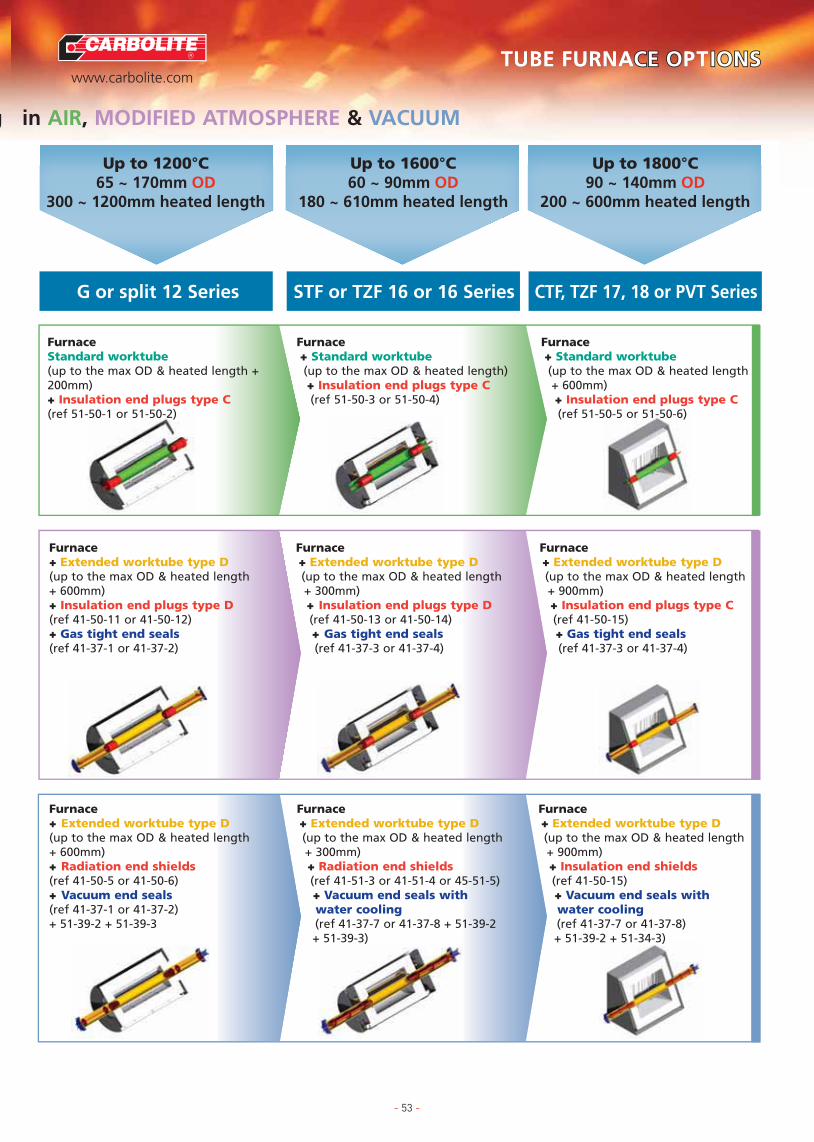
R
www.carbolite.com
TUBE FURNACES
TUBE FURNACE OCE OPTIONSIONS
APPLICATION SPECIFIC FURNACES
TUBE FURNACE OPTIONS
FURNACE OPTIONS & EXTRAS
CHAMBER FURNACES
ASHING & BURN-OFF FURNACES
BESPOKE FURNACES
CUPELLATION FURNACES
G or split 12 Series STF or TZF 16 or 16 Series CTF, TZF 17, 18 or PVT Series
Up to 1200°C65 ~ 170mm OD
300 ~ 1200mm heated length
Up to 1600°C60 ~ 90mm OD
180 ~ 610mm heated length
Up to 1800°C90 ~ 140mm OD
200 ~ 600mm heated length
Furnace+ Extended worktube type D (up to the max OD & heated length+ 300mm)+ Radiation end shields(ref 41-51-3 or 41-51-4 or 45-51-5)+ Vacuum end seals withwater cooling (ref 41-37-7 or 41-37-8 + 51-39-2 + 51-39-3)
Furnace+ Extended worktube type D (up to the max OD & heated length+ 600mm)+ Radiation end shields(ref 41-50-5 or 41-50-6)+ Vacuum end seals(ref 41-37-1 or 41-37-2)+ 51-39-2 + 51-39-3
FurnaceStandard worktube(up to the max OD & heated length +200mm)+ Insulation end plugs type C(ref 51-50-1 or 51-50-2)
g in AIR, MODIFIED ATMOSPHERE & VACUUM
- 53 -
Furnace + Extended worktube type D (up to the max OD & heated length+ 900mm)+ Insulation end shields(ref 41-50-15)+ Vacuum end seals withwater cooling(ref 41-37-7 or 41-37-8)+ 51-39-2 + 51-34-3)
Furnace+ Extended worktube type D (up to the max OD & heated length+ 600mm)+ Insulation end plugs type D (ref 41-50-11 or 41-50-12)+ Gas tight end seals(ref 41-37-1 or 41-37-2)
Furnace + Extended worktube type D (up to the max OD & heated length+ 300mm)+ Insulation end plugs type D(ref 41-50-13 or 41-50-14)+ Gas tight end seals(ref 41-37-3 or 41-37-4)
Furnace + Extended worktube type D (up to the max OD & heated length+ 900mm)+ Insulation end plugs type C(ref 41-50-15)+ Gas tight end seals(ref 41-37-3 or 41-37-4)
Furnace + Standard worktube (up to the max OD & heated length+ 600mm)+ Insulation end plugs type C(ref 51-50-5 or 51-50-6)
Furnace + Standard worktube (up to the max OD & heated length)+ Insulation end plugs type C (ref 51-50-3 or 51-50-4)

R
www.carbolite.com
TUBE FURNACES
TUBE FURNACE OCE OPTIONSIONS
APPLICATION SPECIFIC FURNACES
TUBE FURNACE OPTIONS
FURNACE OPTIONS & EXTRAS
CHAMBER FURNACES
ASHING & BURN-OFF FURNACES
BESPOKE FURNACES
CUPELLATION FURNACES
�� � � � � � �� � � � � � �
� �� �
� � � � �� � � � �
� � �� � �
� � � � � �� � � � � � � �� � � � � � � �
��
� �� � � � � � �
� � �� � �� � �
� � � � � � � � �� � � � � � � � �
Standard Tube Sizes for Up to 1300°CTubeinnerdiam(mm)�
Length (mm) �
� Tube outerdiam(mm)
450
600
750
900
1000
1050
1100
1200
1350
1500
1650
1800
19.5 2625 3228 3438 4638 5150 6053 6160 7064 7375 8375 8677 8778 9180 95100 120110 125117 128125 140134 146152 164150 170
Standard Tube Sizes for Up to 1100°CTubeinnerdiam(mm)�
Length (mm) �
� Tube outerdiam(mm)
19.5 2625 3228 3438 4638 5150 6053 6160 7064 7375 8375 8677 8778 9180 95100 120110 125117 128125 140134 146152 164150 170
�� � � � � � ��(s) �(s) �(s) �(s) �(s) �(s) �(s)
� ��(s) �(s)
� � � � ��(s) �(s) �(s) �(s) �(s)
� � ��(s) �(s) �(s)
� � � � � � � ��(s) �(s) �(s) �(s) �(s) �(s) �(s) �(s)
�(s)�
� �� � � � � � �
�(s) �(s) �(s)� � ��(s) �(s) �(s)
�(s) �(s) �(s) �(s) �(s) �(s) �(s) �(s) �(s)� � � � � � � � �
450
600
750
900
1000
1050
1100
1200
1350
1500
1650
1800
��� �� �� �� �� �� ��(v) �(v) �(v) �(v) �(v) �(v) �(v)
� �� �
�� �� �� �� ���(v) �(v) �(v) �(v) �(v)
� � �� � �
� � � � � �� � � � � � � ��(v) �(v) �(v) �(v) �(v) �(v) �(v) �(v)
�(v)�
� �� � � � � � �
�(v) �(v) �(v)� � ��(v) �(v) �(v)
�(v) �(v) �(v) �(v) �(v) �(v) �(v) �(v) �(v)� � � � � � � � �
Standard Tube Sizes for Up to 1350°CTubeinnerdiam(mm)�
Length (mm) �
� Tube outerdiam(mm)
19.5 2625 3228 3438 4638 5150 6053 6160 7064 7375 8375 8677 8778 9180 95100 120110 125117 128125 140134 146152 164150 170
450
600
750
900
1000
1050
1100
1200
1350
1500
1650
1800
- 54 -
Carbolite wire wound tube furnaces may be used without anaccessory worktube. If however a modified atmosphere orvacuum is required for the application then an accessoryworktube is required. The accessory worktube needs to be longerfor those applications when gas tight or vacuum tight end sealsare required. The degree of extension depends upon the specificfurnace, the temperature and the accessories to be fitted.Contact Carbolite or your local distributor for more information.
Some tube furnaces do not have the element directly woundonto the outer surface of the worktube and in these cases anaccessory worktube is always required.
The intended application determines the best material to use onthe basis of the tube’s operating temperature range, porosity,chemical resistance and tolerance to thermal shock. Towards theupper limits of a worktube’s temperature range the intendedorientation is also important.
Extended tube lengths as well as the added weight of accessoriesfitted to worktube ends may cause them to flex under heating.Use of tube end supports and periodic rotation of the work tubesis recommended to prevent them bending.
Even where samples are only heated in air addition of end plugsgreatly increases uniformity. This is particularly important forlarger diameter tubes over 25mm and for vertical furnaceconfigurations, where convection currents can have a significanteffect on uniformity if end plugs are not used.
Work tubes - temperature & chemical compatibility
Physical & chemical properties Maximumtemperatures in air °C
Tube Material Porous(P) / ‡Resistance ChemicalImpervious to thermal resistance Horizontal Vertical
(I) shock
P Good 1500 1600
I Very good 1400 1500
I Very good 1500 1550
I Good 1800 1900
I Very good 1100 1100
I Excellent 1300* 1350
Silimanite(AL2O3SiO2)
IAP(Impervious aluminous porcelain)
Mullite(3Al2O3.2SiO2.A)
RCA(Recrystalised alumina)
Quartz(Limited availability)
APM** (Advancedpowder metallurgy - FeCrAl alloy)
Good chemicalresistance but
porous
Good chemicalresistance against
gases with theexception of
fluorine
Resistant to fluxsulphurous orcarbonaceousatmospheres
Highly resistant tochemical attack,except fluorine
Generally good butreactive with
sodium & at uppertemperature limit
with metals,carbonates &
halides
Resistant toOxidation,
carburization &sulphidation
* Short or supported tubes only as APM will bend at thistemperature**Unsuitable for use in wirewound outer work tubes due to highelectrical conductivity‡ Resistance to thermal shock is partly dependent upon specifictube geometry
Recommendations are for guidance only and the suitability of amaterial for a specific application can only be confirmed when weknow the complete details of the service conditions.

R
www.carbolite.com
TUBE FURNACES
TUBE FURNACE OCE OPTIONSIONS
APPLICATION SPECIFIC FURNACES
TUBE FURNACE OPTIONS
FURNACE OPTIONS & EXTRAS
CHAMBER FURNACES
ASHING & BURN-OFF FURNACES
BESPOKE FURNACES
CUPELLATION FURNACES
Silimanite �IAP �Mullite �RCA �
� � � � � �
� �
� � � � �
� � �
� � � � � � �
��(v) �(v)
� � �
� � �
�(v) �(v) �(v) �(v) ��(v)��(v) �(v) �(v) �(v)
Standard Tube Sizes for Up to 1600°CTubeinnerdiam(mm)�
Length (mm) �
� Tube outerdiam(mm)
19.5 2625 3228 3438 4638 5150 6053 6160 7064 7375 8375 8677 8778 9180 95100 120110 125117 128125 140134 146152 164150 170
450
600
750
900
1000
1050
1100
1200
1350
1500
1650
1800
� � � � � �
�
� � � � �
� � �
� � � � � � �
�
� � �
� � �
� �
Standard Tube Sizes for Up to 1800°CTubeinnerdiam(mm)�
Length (mm) �
� Tube outerdiam(mm)
19.5 2625 3228 3438 4638 5150 6053 6160 7064 7375 8375 8677 8778 9180 95100 120110 125117 128125 140134 146152 164150 170
450
600
750
900
1000
1050
1100
1200
1350
1500
1650
1800
��� �� �� �� �� �� �
� �
�� �� �� �� ��
� � �
� � � � � �� � � � � � � �
�� �� � � � � � �
� � �
� � � � � � � � �
Standard Tube Sizes for Up to 1400°CTubeinnerdiam(mm)�
Length (mm) �
� Tube outerdiam(mm)
19.5 2625 3228 3438 4638 5150 6053 6160 7064 7375 8375 8677 8778 9180 95100 120110 125117 128125 140134 146152 164150 170
450
600
750
900
1000
1050
1100
1200
1350
1500
1650
1800
�(v) �(v) �(v) �(v) �(v) �(v)
�(v)
�(v) �(v) �(v) �(v) �(v)
�(v) �(v) �(v)
�(v) �(v) �(v) �(v) �(v) �(v) �(v)
�(v)
�(v) �(v) �(v)
�(v) �(v) �(v)
�(v) �(v)
Standard Tube Sizes for Up to 1900°CTubeinnerdiam(mm)�
Length (mm) �
� Tube outerdiam(mm)
19.5 2625 3228 3438 4638 5150 6053 6160 7064 7375 8375 8677 8778 9180 95100 120110 125117 128125 140134 146152 164150 170
450
600
750
900
1000
1050
1100
1200
1350
1500
1650
1800
�(v)�(v)��(v)��(v)��(v)� �(v)� �(v)� �(v)
� �
�� �� �� �(v)� �(v)�
� � �(v)
� � � � � ��(v) �(v) �(v) �(v) �(v) �(v) �(v) �(v)
�(v)� ��(v) �(v) �(v) �(v) �(v) �(v) �(v)
�(v) �(v) �(v)
� � � � � � � � �
Standard Tube Sizes for Up to 1500°CTubeinnerdiam(mm)�
Length (mm) �
� Tube outerdiam(mm)
19.5 2625 3228 3438 4638 5150 6053 6160 7064 7375 8375 8677 8778 9180 95100 120110 125117 128125 140134 146152 164150 170
450
600
750
900
1000
1050
1100
1200
1350
1500
1650
1800
�(v)��(v)��(v)��(v)� �(v)� �(v)�
�(v)� �(v)� �(v)� �(v)� �(v)�
�(v) �(v) �(v) �(v) �(v) �(v)
�� �
� � �
� � �
� � � � �� �� � � �
Standard Tube Sizes for Up to 1550°CTubeinnerdiam(mm)�
Length (mm) �
� Tube outerdiam(mm)
19.5 2625 3228 3438 4638 5150 6053 6160 7064 7375 8375 8677 8778 9180 95100 120110 125117 128125 140134 146152 164150 170
450
600
750
900
1000
1050
1100
1200
1350
1500
1650
1800
Quartz �APM (require supportat this temp) �
Requires support (s)Vertical configuration only (v)
- 55 -
Work tubes - temperature compatibility

R
www.carbolite.com
TUBE FURNACES
TUBE FURNACE OCE OPTIONSIONS
APPLICATION SPECIFIC FURNACES
TUBE FURNACE OPTIONS
FURNACE OPTIONS & EXTRAS
CHAMBER FURNACES
ASHING & BURN-OFF FURNACES
BESPOKE FURNACES
CUPELLATION FURNACES
- 56 -
Work Tube Accessories(◆ Please specify full tube dimensions, furnace model and operating temperature at time of order)
Ceramic insulating plugs ◆
Ceramic fibre board plugs with a 6mm central tube are designed toreduce heat loss from tube ends and are particularly helpful forvertical tubes and tube diameters over 25mm. Two types (C & D) aresupplied for use with standard and extended length work tubesrespectively. Additional support mountings must be ordered for theirinstallation into vertical worktubes.
Radiation shields ◆
Constructed from either ceramic or dust free metal discs on a centraltube, these are used where the porous nature of ceramic plugsmakes them unsuitable. Most often in vacuum applications or wherea high purity atmosphere is required. Additional support mountingsmust be ordered for installation into vertical worktubes.
Gas tight end seals ◆
These comprise stainless steel discs which are equipped with a 6mmgas nozzle as standard or optionally with an NW16, NW25 or NW40flange. Thermocouple glands to accept 1.5mm, 3mm and 10mmprobes can also be added. Gas tight end seals can only used onextended worktubes and are designed to be used in combinationwith insulation plugs or radiation shields (see above).
Water cooled gas tight end seals are recommended where furnacesare to operated at 1500°C or more. These assembles can be used formedium vacuum applications down to 10-3 bar
In order to accommodate the added weight of end seal assembliestube end supports are recommended.
High vacuum end seals ◆
These comprise stainless steel discs which are equipped with anindustry standard vacuum flange. They can only used on extendedworktubes and are designed to be used in combination withradiation shields.
Water cooled high vacuum end seals are recommended wherefurnaces are to operated at 1500°C or more. These assembles can beused for medium vacuum applications down to 10-5 bar
Tube supports ◆
Designed to support extended worktubes and the additional weightof end seal assemblies, they reduce worktube stresses and canimprove a tube’s life expectancy.
C type end plug D type end plug
Metal radiation shieldsCeramic radiation shields
Gas tight end seal with water cooling
19-25 tube seal with NW16
100-120 tube seal with NW40
Optional accessory tube supportsfor STF series
76-86 tube seal with NW25

- 57 -
R
www.carbolite.com
TUBE FURNACES
TUBE FURNACE OCE OPTIONSIONS
APPLICATION SPECIFIC FURNACES
TUBE FURNACE OPTIONS
FURNACE OPTIONS & EXTRAS
CHAMBER FURNACES
ASHING & BURN-OFF FURNACES
BESPOKE FURNACES
CUPELLATION FURNACES
Mounting Configurations
The normal configuration for horizontal tube furnaces in theMTF, CTF, STF and the three zone TZF furnaces is for thefurnace body to be mounted directly onto a control modulebase unit.
However several other options are available at time of order.The furnace body can be mounted on a ‘blanked base’ linkedvia either a 2 or 6 metre power conduit to a second controlmodule containing all of the control electronics.
Alternatively the furnace body can be supplied mounted on aseparate ‘L’ style stand which allows it to be freely positionedseparately from the control module in either a horizontal orvertical position. (Note that different work tube mountingaccessories may be required to change from horizontal tovertical operation, or vice versa).
The furnace body may optionally be supplied separately fromthe base and either completely without a stand or with a wallmounting bracket.
G range tube furnaces are available with a complete ‘G’pattern stand or optionally with just support rail portion ofthe stand (without the foot) with or without a wall mountingbracket.
Split tube furnaces from the HST and HZS ranges areoptionally available for dual vertical and horizontal usemounted upon an ‘L’ style stand. They are also availablecompletely without stands and in a so called ‘farhinge’configuration which enables the split furnace to open widethan the conventional hinge.
VST and TVS range vertical split tube furnaces are similarlyavailable without stands and in ‘farhinge’ designs as analternative to the standard ‘nearhinge’ configuration. The farhinge configuration opens wider to give easer access whenusing large or awkwardly positioned worktube or test pieces.
Normal Construction(Horizontal)
Blanked Base
L-stand: Vertical Use L-stand: Horizontal Use
Wall BracketSeparated Controls
(No Stand)
Optional Far-hinge Standard near-hinge

R
www.carbolite.com
TUBE FURNACES
TUBE FURNACE OCE OPTIONSIONS
APPLICATION SPECIFIC FURNACES
TUBE FURNACE OPTIONS
FURNACE OPTIONS & EXTRAS
CHAMBER FURNACES
ASHING & BURN-OFF FURNACES
BESPOKE FURNACES
CUPELLATION FURNACES
- 58 -
Modified Atmosphere(T Specify at the time of order)
There a number of methods of working in Carbolite furnacesusing a modified, usually inert atmosphere or with vacuum. A range of worktube accessories are listed on page 56 toenable this.
Gas Flow-meters TThe walls of chamber furnaces are frequentlypermeable so gas flow-meters with a standardlength of 100mm and 3% accuracy can beadded.
Inert Gas Inlet TA 6mm hose connection that is usually placed on the furnaceside and connected to the chamber via a ceramic tube. Suitablefor the introduction of inert gas or oxygen. NOTE The introduction of gases may alter heating characteristicsand /or performance characteristics of furnace elements, pleasecontact Carbolite for advice.
Solenoid Valves TElectrically operated valves, activated by a panel mounted switchor using a 3216 or 3508 controller to start or stop gas flows.
Atmosphere Retorts (1100°C) TType A105A range of inconel enclosures sealedby front opening insulated door plugs,gas inlet and outlet connections areeasily accessible towards the front.These should be specified at time oforder so that the door interlockmechanism is modified.
Type A107 TA range of deep Inconel retortssimilar to a pack carburising box,they have a shallow removable lidon top which is seated into a sandseal. Front mounted gas inlets /outlet connections extend throughslots in the modified furnace door.
Inverted Crucible TFor bottom loaded, raised hearth furnaces gasmay be introduced through a modified hearthand retained by an inverted metal bell jar orceramic crucible.
Atmosphere Control System TThis system issuitable for use witheither tube furnacesusing gas tight endseal assemblies ofchamber furnacesusing Type A105retorts. Housed inits own cabinet thesystem isrecommendedwhere hydrogen gas is required forprocessing. It provides greater safety and convenience in controlof hydrogen and nitrogen purge gas. Provides protection whenintroducing hydrogen at low temperatures, provides amonitored burn-off pilot flame and senses failure of gas suppliesand is equipped with hydrogen and nitrogen flow-meters, usinga pressure system. For mass flow systems contact Carbolite.
Entry PortsAccess and Viewing Ports TA 25 mm diameter hole is placed throughthe furnace door in one of two optionalformats; with either a pivoted stainless steelcover disc or a permanent quartz window.
Thermocouple Calibration Port TAn additional thermocouple, similar to the controlthermocouple is built into the furnace and connected tothe a thermocouple socket externally mounted on thecontrol panel, so as to enable connection of temperaturerecorders.
Thermocouple Calibration Port TAn additional ceramic thermocouple sheath is installed adjacentto the control thermocouple. This allows the user to insert areference thermocouple for checking and calibration of thefurnaces controller / thermocouple. Typically this is in the rear ofthe chamber.
SandSeal
InvertedAI2 03Crucible
Gas inlet + outlet
Gas inlet
Gasoutlet
Gasketseal
Insulation
Gasinlet&outlet
Removable lid Sand seal
Flowmeter
Adjustmentvalve
2
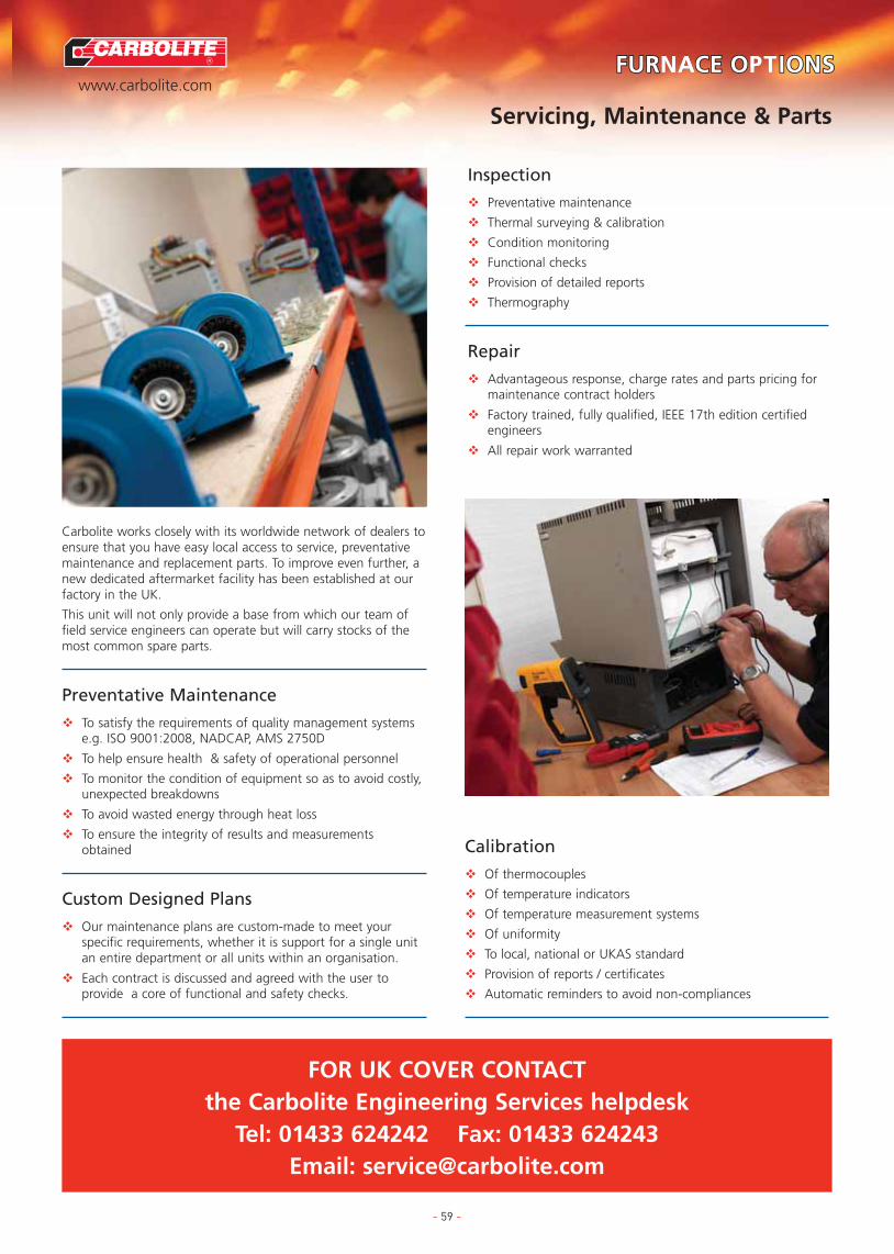
- 59 -
R
www.carbolite.com
TUBE FURNACES
FURTUBE FURNACE OCE OPTIONSIONS
APPLICATION SPECIFIC FURNACES
FURNACE OPTIONS
FURNACE OPTIONS & EXTRAS
CHAMBER FURNACES
ASHING & BURN-OFF FURNACES
BESPOKE FURNACES
CUPELLATION FURNACES
Servicing, Maintenance & Parts
FOR UK COVER CONTACT the Carbolite Engineering Services helpdesk
Tel: 01433 624242 Fax: 01433 624243Email: [email protected]
Carbolite works closely with its worldwide network of dealers toensure that you have easy local access to service, preventativemaintenance and replacement parts. To improve even further, anew dedicated aftermarket facility has been established at ourfactory in the UK.
This unit will not only provide a base from which our team offield service engineers can operate but will carry stocks of themost common spare parts.
Preventative Maintenance
� To satisfy the requirements of quality management systemse.g. ISO 9001:2008, NADCAP, AMS 2750D
� To help ensure health & safety of operational personnel
� To monitor the condition of equipment so as to avoid costly,unexpected breakdowns
� To avoid wasted energy through heat loss
� To ensure the integrity of results and measurementsobtained
Custom Designed Plans
� Our maintenance plans are custom-made to meet yourspecific requirements, whether it is support for a single unitan entire department or all units within an organisation.
� Each contract is discussed and agreed with the user toprovide a core of functional and safety checks.
Inspection
� Preventative maintenance
� Thermal surveying & calibration
� Condition monitoring
� Functional checks
� Provision of detailed reports
� Thermography
Repair
� Advantageous response, charge rates and parts pricing formaintenance contract holders
� Factory trained, fully qualified, IEEE 17th edition certifiedengineers
� All repair work warranted
Calibration
� Of thermocouples
� Of temperature indicators
� Of temperature measurement systems
� Of uniformity
� To local, national or UKAS standard
� Provision of reports / certificates
� Automatic reminders to avoid non-compliances
CarboliteParsons Lane, Hope, Hope Valley S33 6RB, United KingdomTel: +44 (0)1433 620011 Fax: +44 (0)1433 621198e-mail: [email protected] www.carbolite.com
Car
bo
lite
0001
-E-B