lab 3: networking and router hardening - napier40001507/csn11111/lab3.pdf · network security...
TRANSCRIPT

Network Security Networking & Router Hardening – Rich Macfarlane 1
Lab 3: Networking and Router Hardening Rich Macfarlane 2013
2.1 Details
Aim: The aim of this lab is to further introduce the GNS3 network simulator, cover some basic
networking, investigate some network device security vulnerabilities, and perform further
device hardening on Cisco routers.
2.2 Activities
2.2.1 Overview of GNS3 Network Simulator GUI
The GUI for GNS3 is shown in Figure 1, and is divided into four panes by default. The panes can be resized, and opened and closed using the view menu. The pane on the left shows the available network device types which can be added to the network topology. Other custom device types can be added if necessary. The pane on the right is a topology summary. The middle top pane is the network topology workspace, where the topology can be built graphically. The middle bottom pane is the Dynagen console pane, and is the CLI for the Dynamips simulator.
Figure 1 – GNS3 Network Simulator GUI

Network Security Networking & Router Hardening – Rich Macfarlane 2
The GNU3 toolbar is explained in Figure 2 below.
Figure 2 - GNS Toolbar
2.2.2 Create a Network with two Routers
Run the GNS3 Network Simulator, as Administrator, by Right Click>Run as Administrator on
the GNS3 executable.
The New Project dialog should be shown. If not select the File>New Project menu option.
Click the save NVRAMs, and Export router configuration check boxes, as shown below. This is
important, as it allows the device configurations to be saved, along with the topology.
Otherwise the configurations are lost when the project is closed. The project is saved to the
Projects directory, which can be configured from the Edit>Preferences menu. Click OK to
create the project.
Open the Edit>Preferences window and set up the General>directories, and test Dynamips via
Dynamips>Test, if necessary.
Set up the Router IOS Image from Edit>IOS Images... if necessary (download Router Image
also). Remember to remove the Base Config.
Drag two routers onto the topology panel as shown below.
Network Security Networking & Router Hardening – Rich Macfarlane 3
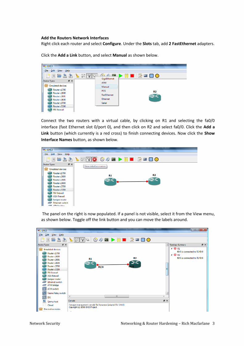
Add the Routers Network Interfaces
Right click each router and select Configure. Under the Slots tab, add 2 FastEthernet adapters.
Click the Add a Link button, and select Manual as shown below.
Connect the two routers with a virtual cable, by clicking on R1 and selecting the fa0/0
interface (fast Ethernet slot 0/port 0), and then click on R2 and select fa0/0. Click the Add a
Link button (which currently is a red cross) to finish connecting devices. Now click the Show
Interface Names button, as shown below.
The panel on the right is now populated. If a panel is not visible, select it from the View menu,
as shown below. Toggle off the link button and you can move the labels around.

Network Security Networking & Router Hardening – Rich Macfarlane 4
To boot all Routers, the Start All button on the toolbar can be used (green play button). The links should turn green.
To open a Console Window for every device, click the toolbar Console button. Press the Enter
key until there is a response from the router, and once the router OSs boot enter no to the initial configuration questions once the routers boot.
2.2.3 Host System Performance Monitoring
It is extremely important to monitor the performance of the host system, and reconfigure the
idlepc value for the device being used, if necessary.
Run the Windows Task Manager using CTRL+SHIFT+ESC (or the Linux System monitor). If the
CPU usage is up at more then 50%, the idlePC value may need to be recalculated. Right click
the Router and select Idle PC. Select the best value, and check the CPU usage, and it should
have reduced.
It is a good idea to keep the Task Manager open and monitor the host system performance
while using GNS3, maybe just hiding most of it off to the side of the visible screen, as shown
below.
When a Cisco IOS is running, it can consume up to 100% of CPU resources, if an idlepc
value is not set. This can cause your system to become sluggish and will prevent building
more complex topologies. However, if an idlepc value is set, CPU usage can be reduced
dramatically (less thean 30% ideally). The IOS is put into a sleep state when it is not in use and
is woken only when it is necessary.

Network Security Networking & Router Hardening – Rich Macfarlane 5
2.2.4 Basic Router Configuration
To assist with the cisco network device CLI commands see:
http://www.cisco.com/en/US/docs/ios/preface/usingios.html
The routers are in User Exec Command Mode, with the Router> prompt. Change to Privilege
Command Mode in both routers.
Q: What signifies that we are in the privileged mode?
Change to Global Configuration Command Mode in both routers.
Q: What signifies that we are in the privileged mode?
Using the hostname command change the hostname of the first router to R1, and the second
to R2 (check the title of the console window to check which router you are connected to).
Check the hostnames have been changed by reviewing the running configuration on each
router.
2.2.5 Saving Cisco Configurations and GNS3 Topology
Cisco Configurations
The running configuration of a Cisco device will be lost when the device is rebooted, as it is stored in RAM. To save changes made to the configuration, it must be copied to the startup configuration which is stored in NVRAM.
Check the current startup configuration:
R1# show startup-config
Q: What is in the startup config?
Use the following command to save the changes to the startup-config to NVRAM, which is not lost when the device reboots.
R1# copy running-config startup-config
Acknowledge the destination, by pressing RETURN, which then copies the current configuration into NVRAM, as shown below

Network Security Networking & Router Hardening – Rich Macfarlane 6
Check the current startup configuration now:
R1# show startup-config
Q: What is in the startup config?
Saving GNS3 Topologies and Device Configurations
When using GNS3, an extra step is needed to save the configuration changes. As the devices are virtual, the copy command must be followed by a File>Save in GNS3. This saves the NVRAM, and exports the configurations to the Projects directory. Otherwise when the GNS3 project is closed, the NVRAM and configuration files are lost. If this fails you can export the configurations manually using File>Import/Export.
Try copying the running-config to startup-config and saving the project. Then use Windows explorer to view the GNS3 Projects directory. View the .cfg files with a text editor to check the router configurations have been saved (the hostnames should be R1 and R2 rather then Router), as shown below.
Make sure you are familiar with this process, and remember to save your work frequently!
Q: Have the running configuration files been saved correctly?
If not, see Rich!
2.2.6 Networking Configuration
Configure the 192.168.10.0/24 network between the two routers. Note: Normally we would
apply security to the devices before networking configurations, but the device security will be
examined in more detail in the next section.
Configure R1 Fast Ethernet Network Adapter
Assign IP Address to the fa0/0 to be able to communicate with R2, using the description
command to add documentation.
R1(config)# interface fa0/0

Network Security Networking & Router Hardening – Rich Macfarlane 7
R1(config-if)# description INT TO THE 192.168.10.0/24 NETWORK
R1(config-if)# ip address 192.168.10.1 255.255.255.0
The no shutdown command, is needed to start the interface for communication
R1(config-if)# no shutdown
R1(config-if)# exit
R1(config)#
The interfaces state should change from DOWN to UP.
*Sep 14 10:41:13.843: %LINK-3-UPDOWN: Interface FastEthernet0/0,
changed state to up
To view the current interface states, use the show ip interface command, as shown
below.
R1# show ip interface brief
Using the Command History Feature The command history feature saves, in a command
history buffer, the commands that you enter during a session. The default number of saved
commands is 10. To recall history commands from the history buffer use the Up Arrow Key for older
commands, and the Down Arrow Key for newer commands. The show history command lists the
most recent command entered.
Use the Up Arrow, to run an earlier command.
Configure R2 Fast Ethernet Network Adapter
Assign a different IP Address on the same network and enable the interface.
R1(config)# interface fa0/0
R1(config-if)# description INT TO THE 192.168.10.0/24 NETWORK
R1(config-if)# ip address 192.168.10.2 255.255.255.0
R1(config-if)# no shutdown
R1(config-if)# exit
R1(config)#
Check the current interface states, and view the running configuration.
Test Connectivity between the R1 and R2 Devices
From R1 use the ping command to test connectivity to the 192.168.10.0/24 network, and
the R2 router. The ping command uses ICMP packets and can be used to check if a device
exists, and is responding. Check the local interface is configured correctly:
R1(config)# ping 192.168.10.1

Network Security Networking & Router Hardening – Rich Macfarlane 8
and then the R2 interface.
R1(config)# ping 192.168.10.2
The output from the ping commands should look something like the following:
Similarly, from R2 use the ping command to test connectivity to R1.
Q: Were the ping commands successful?
If not seek assistance.
Once connectivity has been tested successfully, save R1 and R2 running configurations to the
routers NVRAM, and then save the GNS3 project. Check the configurations have been saved to
the host machine.
2.2.7 Add your Host Machine to the Virtual Network – via a Lookback Interface
There are several ways to incorporate hosts/servers into the GNS3 topology. A virtual PC
simulator, a Virtual Machine (VM), or the host computer itself can be connected as a host
system. In the following example the Host machine will be connected to the GNS3 topology
via a Lookpback Interface.
Configure a Loopback Interface to Connect to Virtual Tolopogy
Check if a loopback network adapter is installed from the Networking and Sharing Centre
dialog (Networking dialog in previous versions of Windows).Check the interfaces from the
Network Connections Window (click Change Adapter Settings) as shown below:

Network Security Networking & Router Hardening – Rich Macfarlane 9
If a loopback network adapter is not installed, a Loopback interface will need to be added on
the local computer (if a Loopback exists, skip to configuration section).
In Windows 7 run hdwwiz from the start prompt or cmd line, or use the Add Hardware wizard
from the Control Panel, (or in other versions of windows click the windows start button ,
and type add hardware).
Select Install the hardware manually, as shown below.
Choose Network Adapters in the list and click Next, as shown below.
Choose Microsoft as the manufacturer and then Microsoft Loopback Adapter as the network
adapter. Finish the wizard.

Network Security Networking & Router Hardening – Rich Macfarlane 10
Configure the Loopback Network Adapter
Select Network Connections (Change Adapter Settings) from the Networking and Sharing
Centre dialog (Networking dialog in previous versions of Windows) as shown below.
You may wish to rename the new Local Area Connection as something like “MS Loopback
Interface”, as shown below.
Right click the loopback interface, and set the network layer IP Addressing to the
192.168.2.0/24, as shown in the below. Click OK, to save the changes.
This loopback has an IP Address on the same TCP/IP network as the routers in GNS3!
Open a Windows command line window, using the Windows Start button and running cmd.
Use the Windows CLI netsh command to check the host systems interfaces and their state, as
shown below.
netsh interface show interface

Network Security Networking & Router Hardening – Rich Macfarlane 11
Add the Host System to the Topology
In GNS3, if you do not have a Host Node, create one using select Edit>Symbol Manager menu
option, and the Symbol Manager window should launch, as shown below.
Click the computer symbol under Available symbols, then click right arrow button between
the windows. This will move the symbol into the Customized nodes column. In the Name box,
type computer. Use the drop-down arrow to change the type to Cloud. Click the Apply button.
Then click OK. In the GNS3 Nodes Types column, you should now see a computer icon.
Drag a computer onto the topology workspace pane, as shown below.

Network Security Networking & Router Hardening – Rich Macfarlane 12
Right Click>Configure the computer C1. Select C1 under clouds, and select the NIO Ethernet
tab. Administrator rights are required for this. Select the network interface to use, in this case
the loopback interface which was set up previously, as shown below. Delete any in already
selected, and click the Add button to add the Loopback, and then OK to finish.
Use the Add a link button, and the Manual option to create your connection from the
Loopback interface to R1 F0/1 interface, as shown below.
At this stage the network layer IP Addresses should be added to GNS3 topology. Double click
each interface on the topology and add the IP Addresses, as shown below.

Network Security Networking & Router Hardening – Rich Macfarlane 13
Configure R1 Interface
Assign an IP Address on the same network as the host, and enable the interface.
R1(config)# interface fa0/1
R1(config-if)# description INT TO THE 192.168.2.0/24 HOST NETWORK
R1(config-if)# ip address 192.168.2.1 255.255.255.0
R1(config-if)# no shutdown
R1(config-if)# exit
R1(config)#
Check the current interface states using show ip int brief, and view the running configuration.
Q: Do the interface states look similar to the following?
If not review the previous configuration steps.
Test Connectivity between the host system and R1 Device
From the host, open a CLI Window from the Windows Start button by typing cmd (use
CTRL+SHIFT+RETURN to run as Administrator), and use the ping command to check the local
loopback interface is enabled and can reply to ICMP packets, as shown below.
Now similarly, use ping to test connectivity to the R1 router interface 192.168.2.1.
Q: Were the ping commands successful?

Network Security Networking & Router Hardening – Rich Macfarlane 14
Test Connectivity between R1 Router and the Host System
From R1 use the ping command to test connectivity to the host, starting with local interface,
then the host interface.
Q: Does the router interface respond?
Q: Does the host PC respond?
Q: If not, what might be causing the problem?
If the PC does not respond, the Windows firewall may be blocking the ICMP packets which the Ping
utility uses.
In Windows7, events can also be logged by the firewall. Open the event viewer, by clicking the
Windows Start button and typing event viewer. In the left pane, click applications and Services
Log > Microsoft > Windows >Windows Firewall With Advanced Security>Firewall, as shown below.
Q: Why might the firewall be set to drop ICMP packets by default on this network interface?
If the firewall is set to log the blocked packets (it doesn’t in this case), we can check the
packets Windows Firewall has blocked. Right click Firewall and select Logs. Or to look at the
firewall log file from the Windows Firewall with Advanced Security>Monitoring. Select the log
filename such as: C:\Windows\System32\logfiles\firewall\pfirewall.log

Network Security Networking & Router Hardening – Rich Macfarlane 15
To turn the firewall off temporarily, on the Loopback Interface click the Windows Start button
. Type Windows Firewall, and open the Windows Firewall with Advanced Security
application.
Select Windows Firewall Properties and select the Public Profile tab.
Click Configure on the Protected Network Connections to see all the networks being
firewalled.
Turn the firewall off for the Loopback interface only, as shown above.
Retest the connectivity between router and loopback. From R1 use the ping command to
test connectivity to the host.
Q: Does the host PC respond to the ping now?

Network Security Networking & Router Hardening – Rich Macfarlane 16
The loopback should now respond to the ping’s ICMP packets as shown below.
Once connectivity has been tested successfully, save R1 and R2 running configurations to the
routers NVRAM, and then save the GNS3 project. (Check the configurations have been saved
to the host machine)
Test Connectivity between the host system and R2 Device
From the host, use the ping command to check connectivity to the R2 router.
Q: Does the host PC respond?
Q: If not, what might be causing the problem?
2.2.8 Routing Network Traffic
We currently have two different networks set up. One between the two routers, and a second
between the host machine and router1. For the traffic to be routed from one network to
another, the routers need to be running routing software. To display the routers routing table
use:
R1(config)# show ip route
Use the following commands to run the rip routing protocol, and add routing for all attached
networks (0.0.0.0), on the R1 router.
R1(config)# router rip
R1(config-router)# network 0.0.0.0
R1(config-router)# exit
R1(config)#
Q: Check the routing table. Has it been populated with routes to networks?
Q: How many routes are directly connected to the router, and how many have been learned from
the rip routing protocol?
Use the following commands to run the rip routing protocol on the R2 router.
R2(config)# router rip
R2(config-router)# network 0.0.0.0

Network Security Networking & Router Hardening – Rich Macfarlane 17
R2(config-router)# exit
R2(config)#
Q: Check the routing table. Has it been populated with routes to any networks?
Q: How many routes are directly connected to the router, and how many have been learned from
the rip routing protocol?
Test Connectivity between R2 Device and the host system
From the R2 router, use the ping command to check connectivity to the host.
Q: Does the host PC respond?
Test Connectivity between the host system and R2 Device
From the host, use the ping command to check connectivity to the R2 router.
Q: Does the R2 router respond?
Q: If not, what might be causing the problem?
If another Wireless or LAN interface on the host is enabled, and has a Default Gateway set, the
traffic may be sent through that interface. If the pings to R2 failed disable any other enabled
interfaces temporarily from the Network Connections dialog. Test the connectivity to the R2
router again.
Q: Does the R2 router respond?
Once connectivity has been tested successfully, save R1 and R2 running configurations to the
routers NVRAM, and then save the GNS3 project. Check the configurations have been saved to
the host machine.

Network Security Networking & Router Hardening – Rich Macfarlane 18
2.2.9 Network Device Hardening – Admin Access Passwords
Console Administrative Access Security – Add Passwords
The simplest way to connect to the device is via the console port, as shown below.
Router Console
Interface
System
Administrator
Router
A console password can be configured and a password added, by using the following commands:
R1(config)#
R1(config)# line con<TAB>
R1(config)# line console 0
R1(config-line)# password conpass
R1(config-line)# login
R1(config-line)# exit
R1(config)#
View the routers configuration file.
Q: Is the console login password readable? (check the line con 0 section of the router config)
Router configurations are often printed out, and may be read by unauthorised staff. They are also typically stored centrally and may be transferred via the FTP or TFTP protocols, which send data in plain text. Therefore it is good practice to encrypt passwords stored in the configuration files.
Password Encryption
Password encryption can be set on Cisco devices, meaning all passwords configured on the router are encrypted. The encryption algorithm used is not a hash cipher (typically used for password staorage), and is fairly easily decrypted. Use the following: R1(config)#
R1(config)# service password-encryption
R1(config)# exit
R1#
View the routers configuration file.
Q: Is the console login password readable?
Q: What threat might this now mitigate?

Network Security Networking & Router Hardening – Rich Macfarlane 19
The default type 7 encryption used by Cisco Devices is not a strong encryption algorithm. Using a simple password cracker the type 7 encoding is easily decoded. Go to the following link and try to crack the console login password.
http://www.firewall.cx/modules.php?name=Cisco_Decrypter
Q: Did you succeed?
Q: Did it take long to crack the passwords?
It should be easily crackable, as shown below:
Using the service password-encryption command only encrypts passwords on the router with the weak type 7 encryption.
Privileged Exec Mode Password –Ecrypt Using MD5 Hash
To encrypt username passwords, the command username secret can be used to encrypt using MD5 hashes. User authentication will be covered in the Access Control Unit.
Set the privileged exec password to cisco.
R1#config t
R1(config)# enable secret cisco
As discussed in Lab1, the enable secret command uses a very secure, one way, MD5 cryptographic hash algorithm which cannot be reversed easily. Cisco devices support various commands to save passwords to the configuration. View the routers configuration file.
Q: Is the privileged command mode password encrypted?
Q: What is the hash digest value?
Q: What is the salt value?

Network Security Networking & Router Hardening – Rich Macfarlane 20
This is a strong encryption algorithm with a salt, but if the password itself is not strong, a simple dictionary attack can crack this, as shown below. This took a few seconds, using Cain, a well known password cracking utility, and a standard dictionary of English words. A much stronger password could also be cracked given enough time.
Cain Cisco Router OS Salted MD5 Password Hash Cracker
By comparing the hashes with pre-computed lookup tables this can be done even quicker, so keeping passwords and password hashes out of the hands of attackers is vital. Methods such as storing passwords centrally, on an Authentication server, are covered in later units.

Network Security Networking & Router Hardening – Rich Macfarlane 21
2.2.10 Remote Administrative Access - Telnet
Telnet Server Administrators typically need to configure devices remotely, as they may not have physical access to plug into the console port. Virtual interfaces (or lines) on the network device can be configured for access to the Routers Telnet server, and the Administrator can administer the device over the LAN using a telnet client, as shown below.
SysAdmin
R1
SysAdmin
R2
SysAdmin
Telnet client
Telnet server
Telnet server
The virtual line password provides authentication for remote administrative access to the router’s telnet service. The following command sets five virtual lines, 0-4. Unless a telnet password is set, access on that virtual line is blocked. Configure virtual terminal lines using:
R1# config t
Enter configuration commands, one per line. End with CNTL/Z.
R1(config)# line vty 0 4
R1(config-line)# password telnetpass
R1(config-line)# login
R1(config-line)# exit
R1(config)#
Telnet Client
Connect from the host system using a telnet client. Telnet is not installed in some versions of
Windows by default (such as Windows 7). To install the Telnet Client, Click the Windows Start
button , go to Control Panel, select Programs and Features, and then select Turn Windows
features on or off.
In the Windows Features dialog box, select the Telnet Client check box, as shown below, and
click OK. The installation may take a minute or two!

Network Security Networking & Router Hardening – Rich Macfarlane 22
From the host system dminister the R1 Router via Telnet
From the host, open a Cmd Window, and use the telnet -? command to check the syntax of the Telnet client tool.
Now, use the telnet 192.168.2.1 command to connect to the telnet server on R1, as shown. Login with the Telnet password you set up.
Now telnet to R2: telnet 192.168.10.2
Q: Did you get access?
Q: Why not?
Set up the Telnet virtual lines on R2, and telnet to R2, but do not login.
Sniffing Telnet Traffic
We can use a packet sniffing application, such as Wireshark to eavesdrop on, and capture, the telnet conversation, as shown in the diagram below. If you would like a tutorial in Wireshark, an optional Lab4 – Packet Capture using Wireshark is available.

Network Security Networking & Router Hardening – Rich Macfarlane 23
SysAdmin
R1
SysAdmin
R2
SysAdmin
Telnet client
Telnet server
Telnet server
Eve
In GNS3, right click on the link between R1 and R2, and select Capture, and select the R2 interface to capture traffic on, as shown below.
This should start Wireshark capturing traffic on the R2 interface. Now telnet to R2, from the host PC CLI, and login to R2 using the virtual line password. Wireshark should display the telnet traffic as shown below.

Network Security Networking & Router Hardening – Rich Macfarlane 24
Using the wireshark capture:
Q: Which Network Layer protocol does Telnet use?
Q: What are the packet numbers of the packets performing the TCP handshake?
Q: Complete the diagram, with client and server ip addresses and port numbers.
Host
Router
IP Address:
_____________
IP Address:
_____________
Port Number:
_____________
Port Number:
_____________
In the top panel, the Packet List Panel - which contains a row per packet, right click on a packet and select Follow TCP Stream. This creates an automatic Display Filter which displays packets from that TCP session only. It also pops up a session display window, containing an ASCII representation of the reassembled TCP session (client packets in red, server packets in blue).
Q: Can you read the telnet session data?
YES/NO
Q: What is shown?
The reassembled data from the telnet packers should look something like shown below:
This highlights the vulnerability in some open protocols, which can be exploited to view, human readable, protocol payloads of conversations of any unencrypted protocols such as HTTP, SMTP, and FTP. For example you can reconstruct web pages seen by a user, or view unencrypted Email/Instant Message conversations.

Network Security Networking & Router Hardening – Rich Macfarlane 25
2.2.11 Remote Administrative Access - Secure Shell (SSH)
SSH is a secure terminal emulation application allowing administrative access to devices with encrypted communications. It can also provide cryptographic authentication of the remote SSH server. Set up the SSH server on Router R1 as follows. SSH Server A domain name needs to be created to use SSH from Cisco IOS:
R1# config t
Enter configuration commands, one per line. End with CNTL/Z.
R1(config)# ip domain-name secure.com
RSA asymmetric cryptography keys are needed by SSH, for authentication, and encryption of traffic. Use a key of 1024 bits and not the Cisco 512 default value, as shown below:
R1(config)# crypto key generate rsa general-keys modulus 1024
The name for the keys will be: R1.secure.com
% The key modulus size is 1024 bits
% Generating 1024 bit RSA keys, keys will be non-exportable...[OK]
R1(config)#
*Sep 21 00:25:58.719: %SSH-5-ENABLED: SSH 1.99 has been enabled
Set a login timeout of 15 seconds, and the number of retries to 3
R1(config)# ip ssh time-out 10
R1(config)# ip ssh authentication-retries 3
Q: Which threats might this help to mitigate?
SSH does not allow the use of the virtual line password to provide authentication for remote administrative access to the router. A user account has to be set up, either locally on the device, or on a Authentication server. The following commands sets up a user/password, and sets the five virtual lines, 0-4 to use SSH instead of telnet:
R1(config)# username admin secret sshpass R1(config)# line vty 0 4
R1(config-line)# transport input ssh
R1(config-line)# login local
R1(config-line)# exit
R1(config)#
Verisfy the SSH server is running using the commands:
R1# show ip ssh
SSH Enabled - version 1.99
Authentication timeout: 10 secs; Authentication retries: 3
Minimum expected Diffie Hellman key size : 1024 bits

Network Security Networking & Router Hardening – Rich Macfarlane 26
SSH Client On the host PC we will use the SSH client Putty.
If Putty is not installed on your system, download from:
http://www.chiark.greenend.org.uk/~sgtatham/putty/
Run wireshark, to capture the SSH session traffic. On the host system, open the Putty application, as shown below, and connect to the SSH Server on R1, selecting Yes to the dialog asking if you trust the SSH Server.
Putty SSH/telnet Client GUI You should be able to login with your user account and password defined on the router, as shown below.
Stop the Wireshark trace. From the trace , follow the TCP Stream for the SSH conversation:
Q: Can you read the SSH session data?

Network Security Networking & Router Hardening – Rich Macfarlane 27
The SSH conversation should look something like shown below:
SSH Encrypted Conversation
Save R1 and R2 running configurations to the routers NVRAM, and then save the GNS3
project. Check the configurations have been saved to the host machine. The final R1
configuration file should look similar to Appendix 1.
Q: Which threats/attacks would SSH help to mitigate?
Q: Research which type of attack could allow the SSH traffic to be read, and give a brief description:

Network Security Networking & Router Hardening – Rich Macfarlane 28
2.3 Appendix 1 - Cisco IOS router configuration
version 12.4
service password-encryption
!
hostname R1
!
boot-start-marker
boot-end-marker
!
logging message-counter syslog
enable secret 5 $1$Er41$tNsvIlqRbUHJ24IjjUU5p0
!
no aaa new-model
ip source-route
ip cef
!
ip domain name secure.com
no ipv6 cef
!
multilink bundle-name authenticated
!
username admin secret 5 $1$qYuv$g8cbnZ3AHUe27cPysahLb.
archive
log config
hidekeys
!
ip ssh time-out 10
!
interface FastEthernet0/0
description to the 192.168.1.0/24 network
ip address 192.168.10.1 255.255.255.0
duplex auto
speed auto
!
interface FastEthernet0/1
description int to the 192.168.2.0/24 network
ip address 192.168.2.1 255.255.255.0
duplex auto
speed auto
!
router rip
network 192.168.2.0
network 192.168.10.0
no auto-summary
!
ip forward-protocol nd
no ip http server
no ip http secure-server
!
line con 0
password 7 0822434019181604
login
stopbits 1
line aux 0
stopbits 1
line vty 0 4
login local
transport input ssh
!
end