lab 26 - reference files for plan sheets · pdf filelab 26 - reference files for plan sheets...
TRANSCRIPT

Colorado Department of Transportation Page 185
LAB 26 - Reference Files for Plan Sheets
Chapter Objectives:
Create plan sheets referencing in files
Clipping reference files
Rotate reference files
Two approaches can be used to assemble plan sheets. In the first part of this chapter the ‘manual’ method of attaching reference files will be used. This is followed by using the InRoads sheet generation command known as the Plan and Profile Generator.
The contents of the reference files are not important to this process and may not accurately reflect the contents and layout of a final plan sheet.
This lab will relocate the border sheet to align with the design graphics.
Moving border sheets to align with design information
In the previous chapter graphics were moved to align with the title sheet. This may suffice for information that is not coordinate dependent but is not an acceptable practice in the generation of engineering drawings. The following workflow will result in a product that conforms to CDOT standards. This first lab uses the ‘manual’ method for designing a plan set layout and assembling the plan sheets. A following lab will use the InRoads Plan and Profile generator command to ‘automate’ the process.
The process for this lab is:
Define the plan sheet limits, rotation, and size(s)
Create a sheet file containing a border for each plan sheet
Attach the appropriate reference files
Rotate sheets normal to the MicroStation view for ease of use
Define reference file clip boundaries

Page 186 Colorado Department of Transportation
LAB 26 - Reference Files for Plan Sheets Labs for ROW Geometry & Plans
1. Open the MicroStation file 12345ROW_Model.dgn
2. Select the MicroStation Fit command to expand the view to show all graphics.
3. Select Element > Cells to verify the ROW cell library is attached.If not, select File > Attach from the Cell Library dialog and attach ROW.cel from the cell library list.

Colorado Department of Transportation Page 187
Labs for ROW Geometry & Plans LAB 26 - Reference Files for Plan Sheets
4. <D><D> rapidly on the cell name RWPL Cuts to identify this as the ‘Placement’ cell and activate the place cell command.
5. In the Place Active Cell dialog, set the X and Y scale to 300, and Active Angle to 0. A Z scale of 1.0 should be used. An X and Y scale of 300 is used because this reflects the scale the survey control diagram sheets will be developed at.

Page 188 Colorado Department of Transportation
LAB 26 - Reference Files for Plan Sheets Labs for ROW Geometry & Plans
About this cell:This cell was created to facilitate the planning of eventual sheets. It contains text characters that can be edited to indicate sheet name, rotation, & scale. The outer line-work depicts the maximum display limits for graphics as it relates to the border sheet. The inside shape reflects ½ inch inside this maximum limit. It also reflects the maximum limits that would be displayed if the sheet was created with the Plan and Profile generator command within InRoads. The ‘dots’ in the vertical lines represent ½ of the sheet height and assist in centering planimetrics information on the sheet. All information is written to the MicroStation level DRAFT_INFO_No-Plot.
6. <D> to place the cell in the MicroStation file, move as necessary. These graphics will define the limits for the plan sheet when referenced back to the border.
The above graphics approximately represent the required limits for the first sheet. Position the sheet limit cell as you see fit.
7. Use the Edit Text command to complete the text at the bottom of the sheet. This will assist in managing the sheets as reference files.

Colorado Department of Transportation Page 189
Labs for ROW Geometry & Plans LAB 26 - Reference Files for Plan Sheets
8. <D> on the text at the bottom of the layout sheet.
9. Replace the appropriate sheet information in the Text Editor as follows:LSCD03C00-00-001”=300’
10. <D> anywhere to accept the change.
11. Use the MicroStation Copy command to duplicate the graphics for the second sheet.

Page 190 Colorado Department of Transportation
LAB 26 - Reference Files for Plan Sheets Labs for ROW Geometry & Plans
12. Use the MicroStation Rotate command to align the graphics for the second sheet (345 degrees, -15 also works).
Replace the appropriate sheet information at the bottom of the copied sheet.
13. In the Text Editor enter:345-00-00
14. Continue planning the sheet layout for the remainder of the project.
Complete a few sheets to understand the concept. It is not the intention of this lab to complete the layout for the entire project.

Colorado Department of Transportation Page 191
Labs for ROW Geometry & Plans LAB 26 - Reference Files for Plan Sheets
Note: Sheets at other scales could also be laid-out at this time. For instance, Monumentation or right of way plan sheets at a scale of 1”=100’
A major benefit of this workflow is that the eventual limits and orientation of sheets are determined early in the process. These sheet limits can be used to identify proper positioning, size, and rotation of text and tables. This is in addition to acting as a guide for attaching the planimetrics to the border sheets.
Assembling the plan sheets
15. Open the MicroStation file ….ROW_Survey\Drawings\ 12345SURV_PlanLSCD3B.dgn
This is a file that you will be using to assemble drawing 4 of this plan subset. This will be accomplished by aligning a cell representing the border with the planimetrics. The current graphics will not be used.
16. Delete the border sheet graphics contained in the MicroStation file.

Page 192 Colorado Department of Transportation
LAB 26 - Reference Files for Plan Sheets Labs for ROW Geometry & Plans
This sheet will be developed at a scale of 1:300. The MicroStation model properties require modification so that the annotation scale matches the plot scale.
17. Open the Models dialog.
18. <D> the Edit Model Properties icon.
19. <D> the drop-down list and select CUSTOM, then input 300:1
20. Set the Line Style Scale to Annotation Scale.
21. <D> OK
22. <D> Yes in the Alert dialog.

Colorado Department of Transportation Page 193
Labs for ROW Geometry & Plans LAB 26 - Reference Files for Plan Sheets
23. Attach the file used in the geometry training portion of this course from the …\ROW_Survey\Drawings\Reference_Files folder;
♦ 12345ROW_Model.dgn
24. Select File > Reference
25. From the References menu select Tools > Attach
26. Highlight the file 12345ROW_Model.dgn and <D> Open.
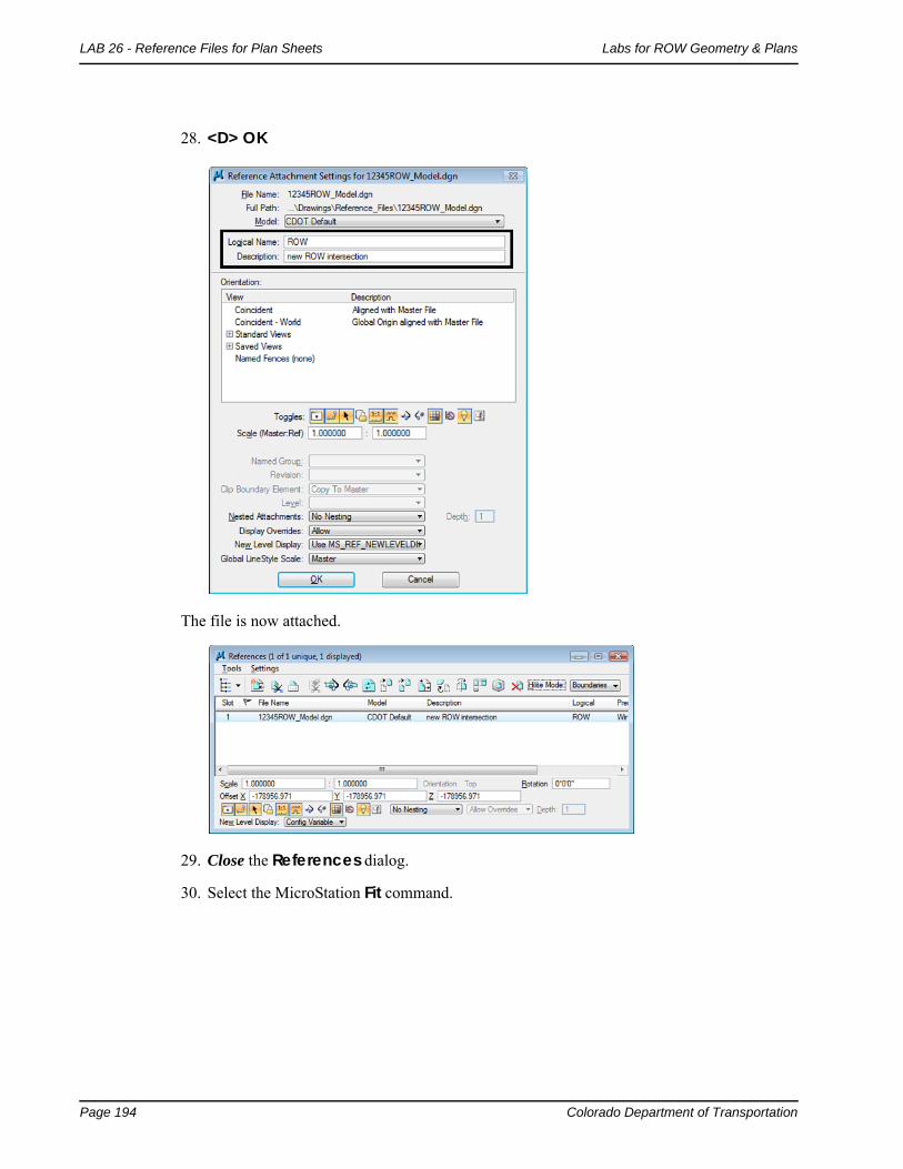
The Reference Attachment Settings dialog appears for the 12345ROW_Model.dgn file.
27. Enter a Logical Name and Description as shown.
Page 194 Colorado Department of Transportation
LAB 26 - Reference Files for Plan Sheets Labs for ROW Geometry & Plans
28. <D> OK
The file is now attached.
29. Close the References dialog.
30. Select the MicroStation Fit command.

Colorado Department of Transportation Page 195
Labs for ROW Geometry & Plans LAB 26 - Reference Files for Plan Sheets
31. Window or Zoom into the beginning of the project.
Note the graphics placed previously to indicate sheet limits.
32. Place the cell called ROW Plan border sheet from the CDOT Menu.
33. <D> Settings to and change the Active Scale to 300 and <D> Apply

Page 196 Colorado Department of Transportation
LAB 26 - Reference Files for Plan Sheets Labs for ROW Geometry & Plans
34. Place the sheet border cell so the lower-left corner coincides with the corner indicated on the sheet limits cell placed previously.
In the Reference dialog, identify the reference file and select Tools > Clip Boundary
35. In the Set Reference Clip Boundary dialog, select the Element Method.

Colorado Department of Transportation Page 197
Labs for ROW Geometry & Plans LAB 26 - Reference Files for Plan Sheets
36. <D> on the shape inset ½ inch from the border.
37. <D> anywhere to accept the clip.
The plan sheet display limits are now constrained to a desirable limit.
38. Turn off level DRAFT_INFO_No-Plot in the reference file 12345ROW_Model.dgn to turn off the sheet lay-outs (Select Settings > Level Display).

Page 198 Colorado Department of Transportation
LAB 26 - Reference Files for Plan Sheets Labs for ROW Geometry & Plans
Make appropriate edits to the title block and add any sheet specific information necessary.
Using the tentative (snap) button <T> to query coordinate values that correctly reflect project coordinates. Additionally an InRoads command, such as tracking, will verify the graphics are coordinately correct.
Once the first sheet is done, the second sheet is much easier. It is easier because the sheet file can be duplicated with the reference files already attached. Moving the border sheet and redefining the clipping boundaries will define subsequent sheets.

Colorado Department of Transportation Page 199
Labs for ROW Geometry & Plans LAB 26 - Reference Files for Plan Sheets
39. Select File > Save as, input name 12345ROWSURVPLlanSheetLSCD3D.dgn
40. <D> Save.
Note: The Save As command will automatically save the current drawing to the hard drive, then copy and rename to the specified file name and open the new drawing.
41. Place a MicroStation fence over an area that would encompass the next sheet in the set.

Page 200 Colorado Department of Transportation
LAB 26 - Reference Files for Plan Sheets Labs for ROW Geometry & Plans
42. In the References dialog, identify the 12345ROW_Model.dgn file and Select Tools > Clip Boundary
43. In the Set Reference Clip Boundary dialog, select the Fence Method.
44. <D> on the MicroStation screen to accept the new clip boundary.
45. Turn On the level DRAFT_INFO_No-Plot in the reference file 12345ROW_Model.dgn to turn the sheet lay-outs back on.

Colorado Department of Transportation Page 201
Labs for ROW Geometry & Plans LAB 26 - Reference Files for Plan Sheets
46. Use the MicroStation Move command to relocate the border sheet. Also Rotate the border sheet to align with the predefined sheet limits.
Rotate the MicroStation view so that the sheet is normal to the view.
47. Key-in rv=0,0,15 (rotate view = value) for this 3D filerv=15 if in a 2D file.
48. <D> on the MicroStation screen to initialize the rotation.
Page 202 Colorado Department of Transportation
LAB 26 - Reference Files for Plan Sheets Labs for ROW Geometry & Plans
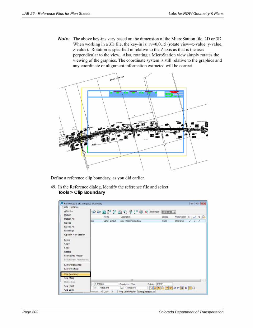
Note: The above key-ins vary based on the dimension of the MicroStation file, 2D or 3D. When working in a 3D file, the key-in is: rv=0,0,15 (rotate view=x-value, y-value, z-value). Rotation is specified in relative to the Z axis as that is the axis perpendicular to the view. Also, rotating a MicroStation view simply rotates the viewing of the graphics. The coordinate system is still relative to the graphics and any coordinate or alignment information extracted will be correct.
Define a reference clip boundary, as you did earlier.
49. In the Reference dialog, identify the reference file and select Tools > Clip Boundary
Colorado Department of Transportation Page 203
Labs for ROW Geometry & Plans LAB 26 - Reference Files for Plan Sheets
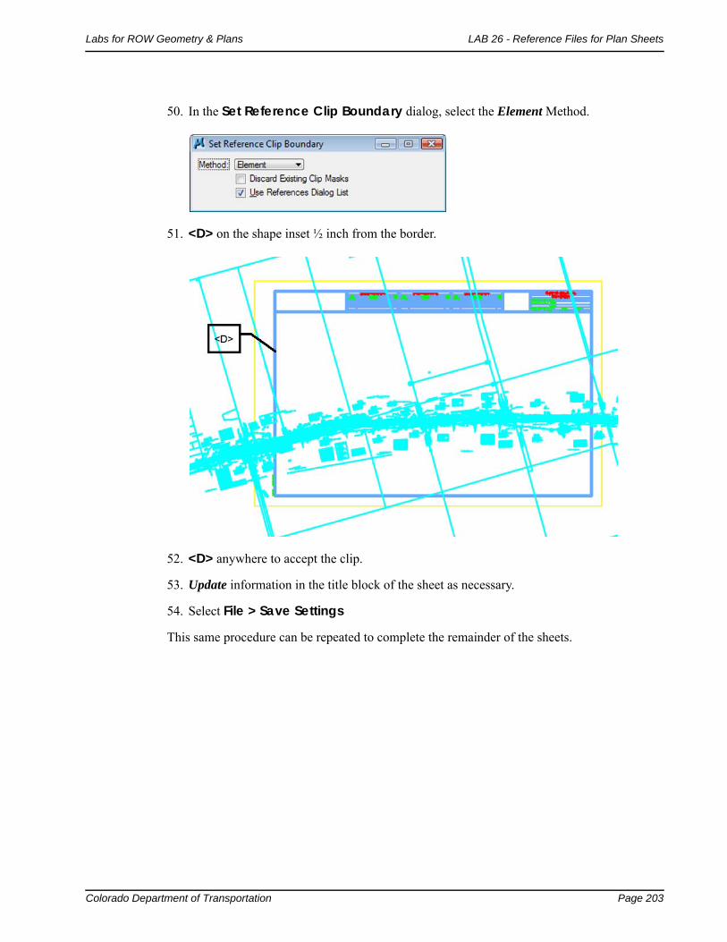
50. In the Set Reference Clip Boundary dialog, select the Element Method.
51. <D> on the shape inset ½ inch from the border.
52. <D> anywhere to accept the clip.
53. Update information in the title block of the sheet as necessary.
54. Select File > Save Settings
This same procedure can be repeated to complete the remainder of the sheets.

Page 204 Colorado Department of Transportation
LAB 26 - Reference Files for Plan Sheets Labs for ROW Geometry & Plans