la protection s élective des r éseaux électriques - accueil · first objectives of the...
TRANSCRIPT

La protection sélective des réseaux électriques. .ULG 21 11 2012
ULg 21/11/2012
© Siemens AG 2006Power Transmission and DistributionA.Belvaux

The T&D grids
Generation Transmission Distribution Industry
ULg 21/11/2012
© Siemens AG 2006Power Transmission and DistributionA.Belvaux

The electricity network ensure an efficient supply of energy
High Voltage Transformers Medium VoltageComponents, switchgear and turnkey projects for AC and DC power
Components, switchgear and turnkey projects for AC and DC power
Power transformers, distributiontransformers with oil or cast-resin projects for AC and DC power
technology for power transmission ≤ 52 kV.
projects for AC and DC power technology for power transmission > 52 kV.
transformers with oil or cast-resininsulation.
ULg 21/11/2012
© Siemens AG 2006Power Transmission and DistributionA.Belvaux
Energy AutomationNetwork control systems, protectionand substation automation, telecontrol systems, power quality.
ServicesNetwork planning & consulting, asset maintenance and maintenance management for grids and networks, metering services.

Energy flow in electricity networks
Main power stationMain power stationMain power stationMain power stationWindWindWindWind
HydroHydroHydroHydro
15 15 15 15 kVkVkVkV
150 150 150 150 kVkVkVkV
StorageStorageStorageStorage
CombinedCombinedCombinedCombinedindustrialindustrialindustrialindustrialprocessesprocessesprocessesprocesses
BiomassBiomassBiomassBiomass
Fuel cellFuel cellFuel cellFuel cell150 150 150 150 kVkVkVkV
15 15 15 15 kVkVkVkV
....0000 4 4 4 4 kVkVkVkV
++++ ----
ULg 21/11/2012
© Siemens AG 2006Power Transmission and DistributionA.Belvaux
DomesticDomesticDomesticDomestic IndustryIndustryIndustryIndustry
....0000 4 4 4 4 kVkVkVkV
DomesticDomesticDomesticDomesticCombinedCombinedCombinedCombinedheat powerheat powerheat powerheat power
SolarSolarSolarSolar
StorageStorageStorageStorage ....0000 4 4 4 4 kVkVkVkV

Key Product for High VoltageNetwork: Circuit Breaker
63
50
40
Rated short-circuit breaking current [kA]
80
3AT2/3 3AT4/5
ULg 21/11/2012
© Siemens AG 2006Power Transmission and DistributionA.Belvaux
31,5
25
072,5 123 145 300 362 420 550 800
Rated voltage [kV]170 245
3AP1 FI3AP1 FG 3AP2 FI

Coils� Air Core Dry Type
Reactors
Arrester� HV:
AIS (Porcellain, Polymer)
Products for High VoltageArrestors, Bushings, Coils & Instrument Transformer s
Instrument Transformers� Current Transformers
Bushings� Air Core Dry Type Reactors
Reactors� Line Traps� Arc Suppression Coils
AIS (Porcellain, Polymer) & GIS; HVDC, FACTS
� MV: Distribution & Traction Vehicles
ULg 21/11/2012
© Siemens AG 2006Power Transmission and DistributionA.Belvaux
� Current Transformers� Voltage Transformers
� Air Core Dry Type Reactors� Line Traps� Arc Suppression Coils

Gas Insulated Switchgear (GIS) 8DN9 switchgear
�Rated voltage up to 245 kV
�Rated frequency 50 / 60 Hz
�Rated power frequency�Rated power frequency
withstand voltage (1 min) up to 460 kV
�Rated lightning impulse
withstand voltage (1,2/50 µs) up to 1050 kV
�Rated busbar current up to 3150 A
�Rated feeder current up to 3150 A
�Rated breaking current up to 50 kA
�Rated short-time current up to 50 kA
�Leakage rate per year and
ULg 21/11/2012
© Siemens AG 2006Power Transmission and DistributionA.Belvaux
�Leakage rate per year and
gas compartment < 0.5 %
�Bay width 1500 mm
�Bay height 3500 mm
�Bay depth 4700 mm
�Bay weight 5 t

� High reliability
� Excellent field experience with more than 2
Medium Voltage ComponentsVacuum Tubes
million vacuum interrupters
� Tailormade development
� Wide product range for any application
� For use in
� LV and MV circuit-breakers, load-break
switches and contactors
ULg 21/11/2012
© Siemens AG 2006Power Transmission and DistributionA.Belvaux
switches and contactors
� Autoreclosers
� Transformer Tap Changers
Delivery Program
690 up to 1300 V up to 65 kA up to 2500 A
7.2 up to 40.5 kV up to 72 kA up to 6300 A

Energy Automation
Do lor situs cum habilitarum itum alus causticus
� Information and network control technologyalus causticus
imanenter Status landum exus rius laudanum tum.
Lorem exit vulnareus plexus est. Vulna pausta rhus tex, per
technology
� Protection and substation auto-mation, telecon-trol systems, power quality
ULg 21/11/2012
© Siemens AG 2006Power Transmission and DistributionA.Belvaux
pausta rhus tex, per itum falor sit wunt. Sit itum causticus aurum eum et expli ndus.Cum

-detect fault and isolate only the faulted part of the power system
First objectives of the „SELECTIVE PROTECTION“
-ensure the greatest possible level of the grid and supply reliability
-limit the effect of faults on the equipments (cabl e , transformer,..)
ULg 21/11/2012
© Siemens AG 2006Power Transmission and DistributionA.Belvaux
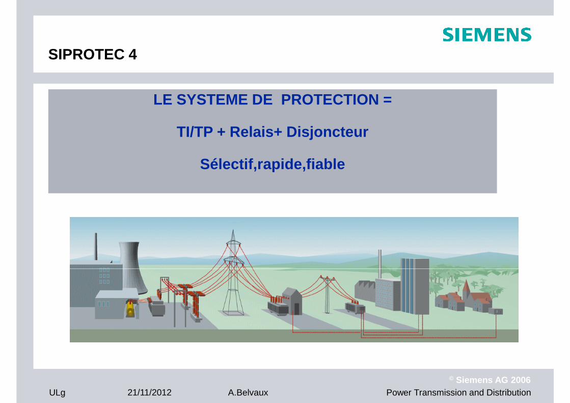
LE SYSTEME DE PROTECTION =
TI/TP + Relais+ Disjoncteur
SIPROTEC 4
TI/TP + Relais+ Disjoncteur
Sélectif,rapide,fiable
ULg 21/11/2012
© Siemens AG 2006Power Transmission and DistributionA.Belvaux

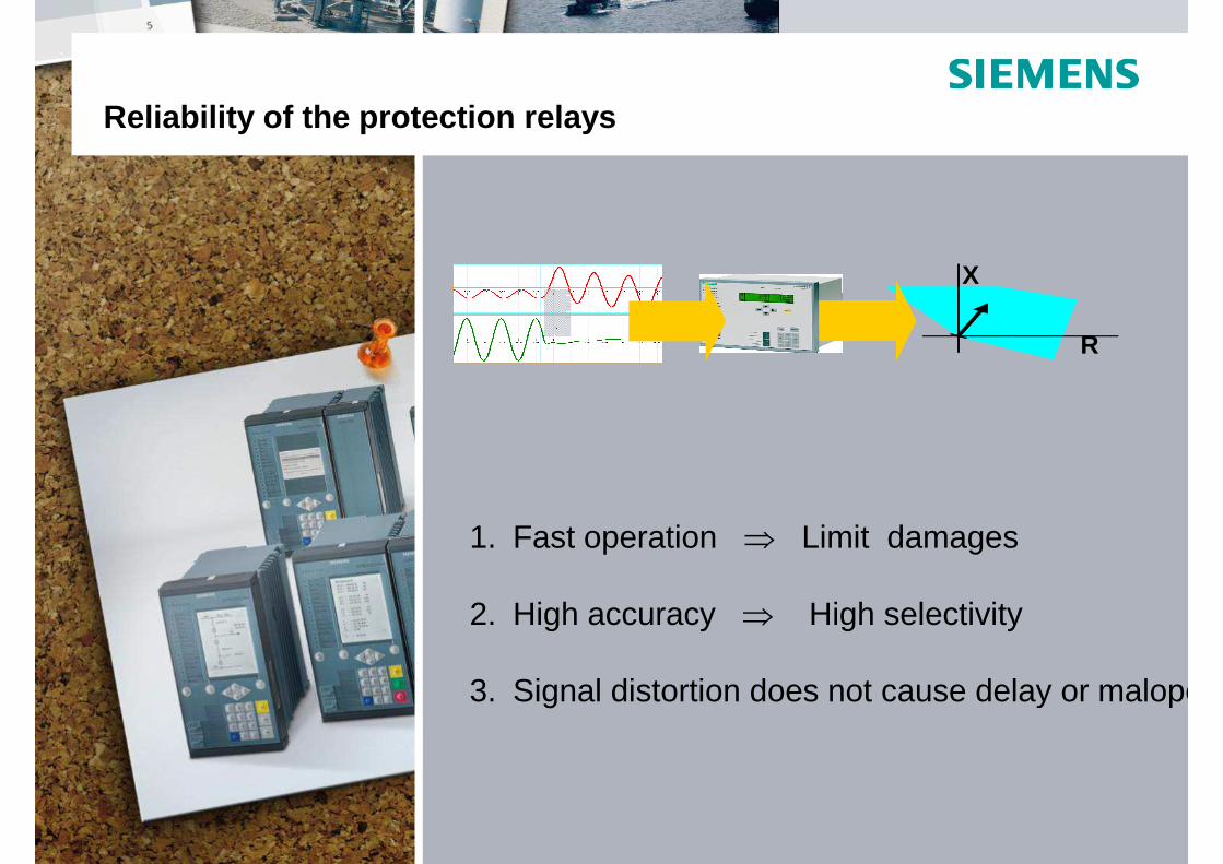
Reliability of the protection relays
X
1. Fast operation ⇒ Limit damages
R
ULg 21/11/2012
© Siemens AG 2006Power Transmission and DistributionA.Belvaux
2. High accuracy ⇒ High selectivity
3. Signal distortion does not cause delay or maloperation

SIPROTEC more than 100 Years of Experience
1910 1960 1970 1980 1990 2000 2012
ULg 21/11/2012
© Siemens AG 2006Power Transmission and DistributionA.Belvaux
Analog Relays
Electromechanical Relays
Numerical Protection Relays

O/C protection
ULg 21/11/2012
© Siemens AG 2006Power Transmission and DistributionA.Belvaux
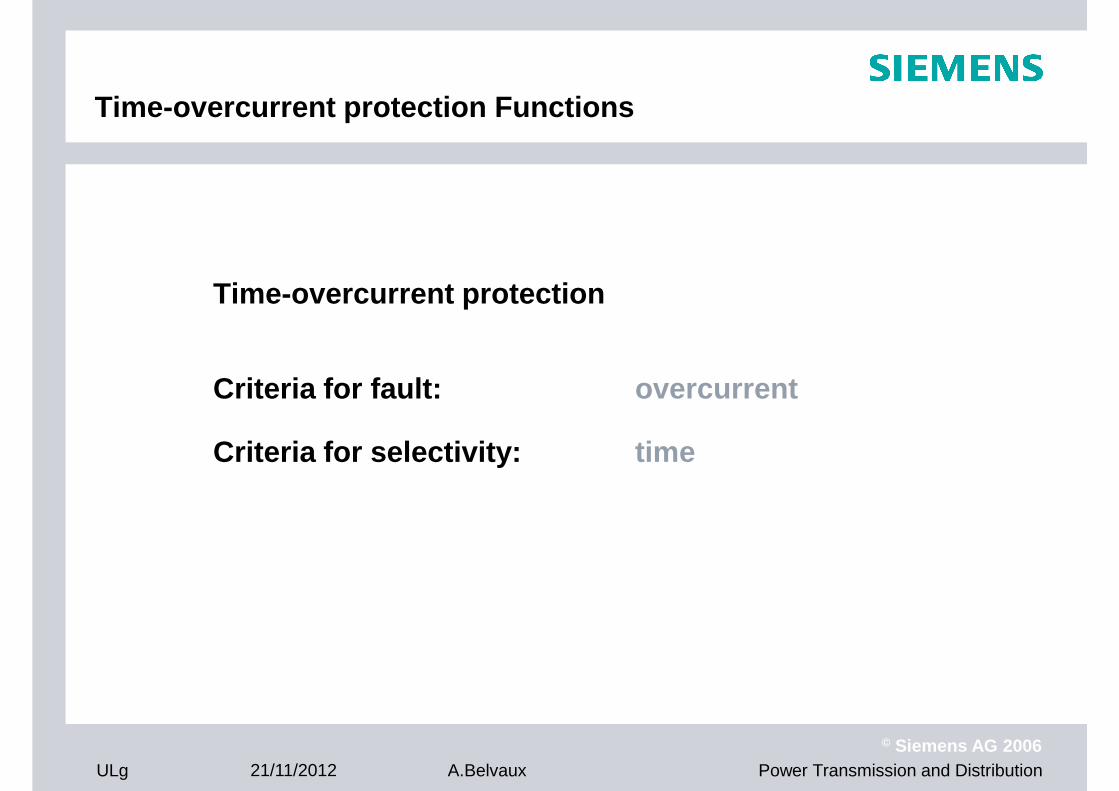
Time-overcurrent protection Functions
Time-overcurrent protection
Criteria for fault: overcurrent
Criteria for selectivity: time
ULg 21/11/2012
© Siemens AG 2006Power Transmission and DistributionA.Belvaux

Time-overcurrent protection Characteristics
Tripping characteristic of a two stage time-overcur rent protection device - definite time
t [sec]
1.0
1.5
2.0
Tripping area
protection device - definite time
ULg 21/11/2012
© Siemens AG 2006Power Transmission and DistributionA.Belvaux
0.5
x IN0.5 1.0 1.5 2.0 2.5I> I>>

Time-overcurrent protection Application
Main protection as line protection
x x x x
O/C O/C O/C O/C
t = 0mst = 300mst = 600mst = 900ms
Ttripbackup
ULg 21/11/2012
© Siemens AG 2006Power Transmission and DistributionA.Belvaux
Advantage: simple device,only current transformers are necessary
Disadvantage: near infeed higher tripping time
distance
up
Distance protectionDistance protection
ULg 21/11/2012
© Siemens AG 2006Power Transmission and DistributionA.Belvaux

Why impedance protection?
Situation: Meshed network and two infeedsDirectional overcurrent time relays
0,6s
0,6s
0,3s
0,3s
ULg 21/11/2012
© Siemens AG 2006Power Transmission and DistributionA.Belvaux
0,6s
0,6s
0,3s
0,3s
non-selective trip

Localization of short-circuits by means of an impedance measurement:
� fault on the protected line Z1
Basic principle of impedance protection
� fault on the protected line
� fault outside the protected line
Z1
relay A
relay A
Z2
ULg 21/11/2012
© Siemens AG 2006Power Transmission and DistributionA.Belvaux
selectivity

Distance measurement (principle)
ZL = RL + j XLIL1
IL2
Z
L
6 loops: 3 phase- phase loops and3 phase- ground loops
phase- phase -loop:
ZE = RE +j XEIL3
IE Z
EUL1UL2UL3
ULg 21/11/2012
© Siemens AG 2006Power Transmission and DistributionA.Belvaux
phase- phase -loop:
The same applies to the remaining loops
UL1-L2 = ZL ( IL1 - IL2)
Measured currentmeasured voltage
06.08.97dtgerdis3

Distance measurement (principle)
IL1
IL2
ZL
ZL = RL + j XL
phase-ground-loop: UL1 = ΙL1 · ( RL + j XL )- ΙE · ( RE +j XE)
IL2
IL3
IE Z
EUL1UL2UL3
ZL = RL + j XL
ZE = RE +j XE
ULg 21/11/2012
© Siemens AG 2006Power Transmission and DistributionA.Belvaux
ΙL1, ΙE measured currentUL1 measured voltage
06.08.97dtgerdis3
The same applies to the remaining loops

UU tjj eUeUU ωϕ ⋅=⋅=
Impedance calculation using U- and I-phasors
R Z
II tjj eIeII ωϕ ⋅=⋅=
II t⋅=ωϕ
UU t⋅=ωϕ
0=t
IUZ ϕϕϕ −=
( ) XjRjZeZZ ZZj Z ⋅+=⋅+⋅=⋅= ϕϕϕ sincos
X
ULg 21/11/2012
© Siemens AG 2006Power Transmission and DistributionA.Belvaux
( ) ( ) ( )IUIUj
j
j
I
Uj
I
Ue
I
U
eI
eU
I
UZ IU
I
U
ϕϕϕϕϕϕϕ
ϕ
−+−⋅=⋅=⋅⋅== − sincos
R X

Numerical filtered phasor measurement
X
1. Fast operation ⇒ Use short data window
R
ULg 21/11/2012
© Siemens AG 2006Power Transmission and DistributionA.Belvaux
1. Fast operation ⇒ Use short data window
2. High accuracy ⇒ High selectivity
3. Signal distortion does not cause delay or maloperation

ni2sin ⋅π
Fourier analysis of measured values
Sampled
C(k)S(k)(k) j III ⋅+=S(k)I
C(k)Ij ⋅ )(kI
)( inki +−
k-n
0 1 2 . . . n
i
C(k)Ik
Sampledmeasuring values
Resulting phasor
ULg 21/11/2012
© Siemens AG 2006Power Transmission and DistributionA.Belvaux
ni2cos ⋅π
C(k)Ij ⋅
ϕS(k)I

Load and short-circuit impedances
ZL
ZLF1
ZLF2
distance relayoperating characteristic
RF RF
ZLoadDF1 F2
X
ZL
ZLF2
j L
RR
ZF1
ZF2
RR
ZLoad
ZLF1
Fault area
Phase - Phase Fault
RR ≈ RF / 2
Phase - Earth Fault
ULg 21/11/2012
© Siemens AG 2006Power Transmission and DistributionA.Belvaux
Rj SC1
j SC2
j L
Fault in reverse
direction Load area
Minimum Load Impedance:Minimum voltage 0,9 UnMaximum current 1,1 InMaximum angle ± 30°
RR ≈ RF /(1 + RE/RL)

X
Z5
Line
Impedance zones of digital relays
Distance zones
Inclined with line angle ϕAngle α prevents overreach of
R
ϕϕϕϕ LoadLoad
Z1
Z2
Z4
Z1B
Z5
αααα
Angle α prevents overreach of Z1 on faults with fault resistance that are fed from both line ends
Fault detection
no fault detection polygon: the
ULg 21/11/2012
© Siemens AG 2006Power Transmission and DistributionA.Belvaux
Z3
no fault detection polygon: the largest zone determines the fault detection characteristic
simple setting of load encroachment area with Rmin and ϕLoad

Graded distance zones
time t3Z2
Z3
∆t = grading time
D1 D2 D3
t1
t2Z1
distance
A CB D
Grading rules:
ULg 21/11/2012
© Siemens AG 2006Power Transmission and DistributionA.Belvaux
Z1 = 0,85 ZAB
Z2 = 0,85 (ZAB + 0,85 ZBC)Z3 = 0,85 (ZAB + 0,85 (ZBC + 0,85 ZCD))
Safety margin is 15 %:� line error� CT, VT error� measuring error
Grading rules:

Ring feeder: with grading against opposite end
0.6
grading time(s)0.6
0.3
ULg 21/11/2012
© Siemens AG 2006Power Transmission and DistributionA.Belvaux
The same grading from both sides

Differential protection
ULg 21/11/2012
© Siemens AG 2006Power Transmission and DistributionA.Belvaux
I1
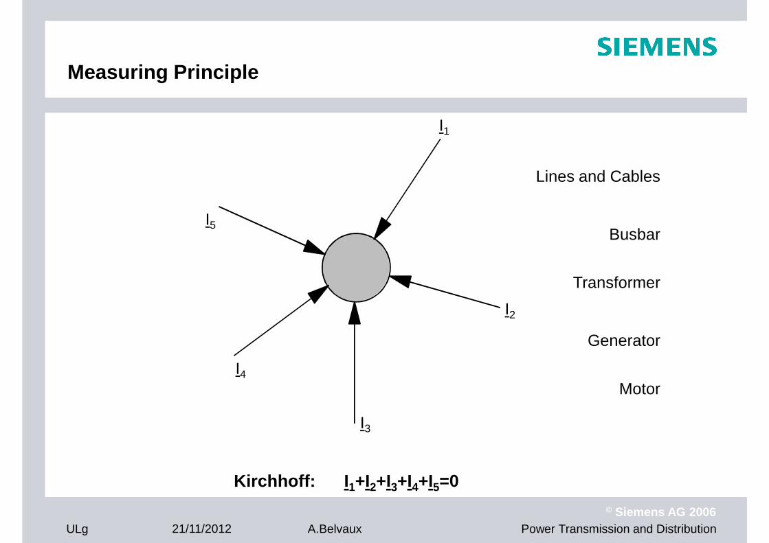
Measuring Principle
Lines and Cables
I2
I
I5
Lines and Cables
Busbar
Transformer
Generator
ULg 21/11/2012
© Siemens AG 2006Power Transmission and DistributionA.Belvaux
Kirchhoff: I1+I2+I3+I4+I5=0
I3
I4Motor

Line differential protection
over 3 line ends
7SD52
ULg 21/11/2012
© Siemens AG 2006Power Transmission and DistributionA.Belvaux
7SD52
7SD52

No restrictions for communicationNo restrictions for communication
� Communication with …
� direct FO connection up to 100 km
� digital communication network (G703, X21)
� ISDN-connection
� 2 or 3 wire pilot wire (twisted, screened)
FO
or
ULg 21/11/2012
© Siemens AG 2006Power Transmission and DistributionA.Belvaux
Digitalcommunication network
or7SD
5
ISDN
or2/3 wire pilot wire (Cu)
or
7SD
5OEEO
EO
EO
OE
OE

Transformer differential protection
UN1 = 110kV UN2 = 30kV
SN = 100MVA
IP1 = 500A(load current)
IP2 = 1833A(load current)
1000/5A 2000/5A
winding 1 winding 2
7UT512
IN, Trafo = 525A IN, Trafo = 1924A
IS1 = 2.5A IS2 = 4.58A measuredsecondary currents
ULg 21/11/2012
© Siemens AG 2006Power Transmission and DistributionA.Belvaux
IDiff = ? IStab= ?

Method of Vector Group Determination
Side 2: Side 1:
1L12L1
2L2
IL1,S1IL1,S2 = IL1 - IL2
1L2
1L3
2L2
2L3
ULg 21/11/2012
© Siemens AG 2006Power Transmission and DistributionA.Belvaux
330°(n * 30°)
Vector group is
Y d 11

Current transformer saturation
Saturation during steady-state current
ULg 21/11/2012
© Siemens AG 2006Power Transmission and DistributionA.Belvaux
Saturation during offset current

Idiff fault line (k=1)
Ideal internal fault
� Idiff = I1
Trip Characteristic
Idiff fault line (k=1)
internal fault
external fault oroperation condition
� Idiff = I1
� Istab = I1
� fault is on fault line
External fault
� Idiff = 0
ULg 21/11/2012
© Siemens AG 2006Power Transmission and DistributionA.Belvaux
Istab
� Istab = |I1|+|I2|+...|In|
security for CT deviations

X X X X
Busbar protection - summation transformer version
X
1
X
2
X
3
X
7
. . .
100 mA
ULg 21/11/2012
© Siemens AG 2006Power Transmission and DistributionA.Belvaux
Summation transformer 4AM5120

Distributed System
substation
central unit
.
terminal panel terminal panel terminal panel terminal panel
22 22
fibre optics
1,5 km
bay unit
ULg 21/11/2012
© Siemens AG 2006Power Transmission and DistributionA.Belvaux
50
terminal panel
50
terminal panel
50
terminal panel
50
terminal panel
Reliability of the protection relays
X
1. Fast operation ⇒ Limit damages
X
R
ULg 21/11/2012
© Siemens AG 2006Power Transmission and DistributionA.Belvaux
2. High accuracy ⇒ High selectivity
3. Signal distortion does not cause delay or maloperation

Power System Influencesi1
t
i1
t
Inrush currents
Transformer overexcitation
CT saturation
t/s0,995 1,000 1,005 1,010 1,015 1,020 1,025 1,030 1,035 1,040 1,045 1,050
U/V
-100
-50
0
50Non system frequent voltages with capacitive voltage transformers
-XC
Leitung
R
X
-XC
Leitung
R
X
Variable system impedances with FACTS
GAP
MOV
ZS
GAP
MOV
ZS
Sub-synchronous frequencies with series compensation
ULg 21/11/2012
© Siemens AG 2006Power Transmission and DistributionA.Belvaux
High equipment and route capacity
utilization
i/kA
t/ms500
u/kV
t/ms500
200
-3
6
3
i/kA
t/ms500
u/kV
t/ms500
200
-3
6
3
Power swings
Inter-area oscillations