l6470 discovery: development tool to explore l6470 motor
TRANSCRIPT
For further information contact your local STMicroelectronics sales office.
March 2015 DocID025447 Rev 4 1/9
EVAL6470H-DISC
L6470 Discovery: development tool to explore L6470 motor driver
Data brief
Features
Voltage mode driving featuring extreme smoothness
Up to 1/128 microstepping
Fully autonomous solution embedding an STM32™ MCU and the L6470H stepper motor driver
Compatible with SPIN family evaluation software
Wide voltage range from 8 V to 45 V
High phase current up to 3 Ar.m.s
Footprint optimized for external resonator or crystal
Switch motor input control
Keys start/left - stop/right - reset
Ready, busy, error LED indicators
Spare LED indicators for specific design
Adjustable supply voltage compensation
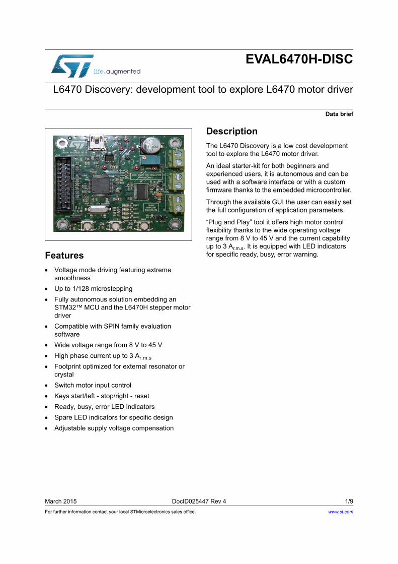
Description
The L6470 Discovery is a low cost development tool to explore the L6470 motor driver.
An ideal starter-kit for both beginners and experienced users, it is autonomous and can be used with a software interface or with a custom firmware thanks to the embedded microcontroller.
Through the available GUI the user can easily set the full configuration of application parameters.
“Plug and Play” tool it offers high motor control flexibility thanks to the wide operating voltage range from 8 V to 45 V and the current capability up to 3 Ar.m.s. It is equipped with LED indicators for specific ready, busy, error warning.
www.st.com
Board description EVAL6470H-DISC
2/9 DocID025447 Rev 4
Board description
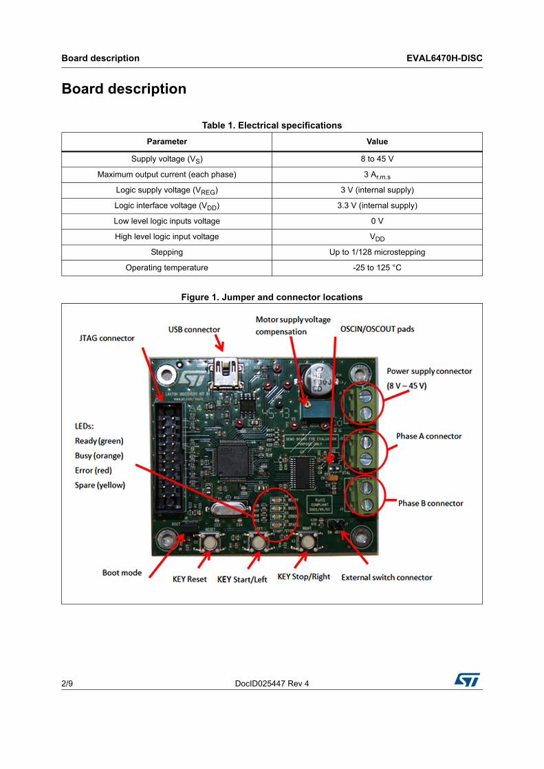
Figure 1. Jumper and connector locations
Table 1. Electrical specifications
Parameter Value
Supply voltage (VS) 8 to 45 V
Maximum output current (each phase) 3 Ar.m.s
Logic supply voltage (VREG) 3 V (internal supply)
Logic interface voltage (VDD) 3.3 V (internal supply)
Low level logic inputs voltage 0 V
High level logic input voltage VDD
Stepping Up to 1/128 microstepping
Operating temperature -25 to 125 °C

DocID025447 Rev 4 3/9
EVAL6470H-DISC Board description
9
Table 2. Jumpers and connectors
Name Function
J1 Motor supply voltage
J2 Bridge B output
J3 Bridge A output
J4 Debug JTAG function
J5 USB function
J6 Boot mode
J7 External switch input
R29 OSCIN and OUSCOUT pins
TP1 VDD - logic supply voltage
TP2 VS - motor supply voltage
TP3 GND - ground test point
TP4 UART RX - debug test point
TP5 UART TX - debug test point
TP6 UART CK - debug test point
TP7 Motor voltage compensation test point
Table 3. JTAG connector pinout (J4)
Name Type Function
1 - 2 Supply EXT_VDD
3 Digital I/O External RESET
5 Digital I/O INPUT (TDI)
7 Digital I/O Mode select (TMS)
9 Digital I/O Clock (TCK)
13 Digital I/O OUTPUT (TDO)
15 Digital I/O Internal RESET
11 - 17 - 19 Digital I/O Pull-down
4 - 6 - 8 - 10 - 12 - 14 - 16 - 18 - 20 Ground Ground

Board description EVAL6470H-DISC
4/9 DocID025447 Rev 4
Figure 2. Schematic (power supply part)
Figure 3. Schematic (microcontroller control part)
DocID025447 Rev 4 5/9
EVAL6470H-DISC Board description
9
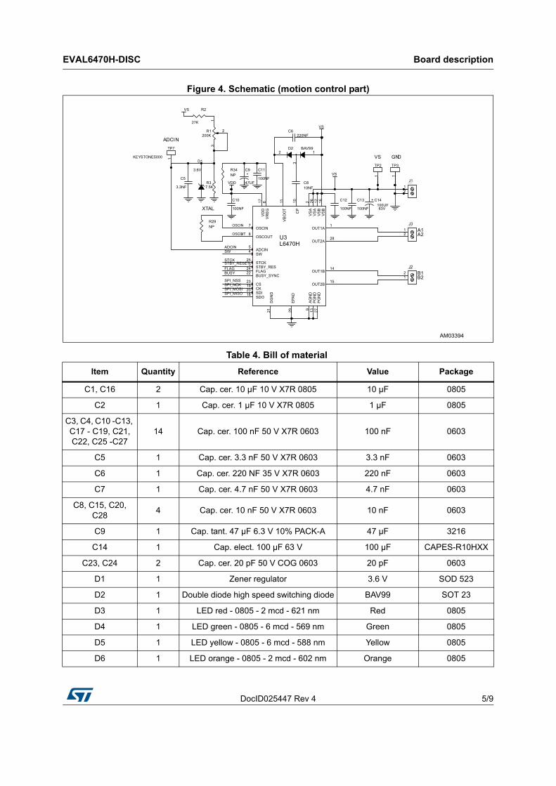
Figure 4. Schematic (motion control part)
Table 4. Bill of material
Item Quantity Reference Value Package
C1, C16 2 Cap. cer. 10 µF 10 V X7R 0805 10 µF 0805
C2 1 Cap. cer. 1 µF 10 V X7R 0805 1 µF 0805
C3, C4, C10 -C13, C17 - C19, C21, C22, C25 -C27
14 Cap. cer. 100 nF 50 V X7R 0603 100 nF 0603
C5 1 Cap. cer. 3.3 nF 50 V X7R 0603 3.3 nF 0603
C6 1 Cap. cer. 220 NF 35 V X7R 0603 220 nF 0603
C7 1 Cap. cer. 4.7 nF 50 V X7R 0603 4.7 nF 0603
C8, C15, C20, C28
4 Cap. cer. 10 nF 50 V X7R 0603 10 nF 0603
C9 1 Cap. tant. 47 µF 6.3 V 10% PACK-A 47 µF 3216
C14 1 Cap. elect. 100 µF 63 V 100 µF CAPES-R10HXX
C23, C24 2 Cap. cer. 20 pF 50 V COG 0603 20 pF 0603
D1 1 Zener regulator 3.6 V SOD 523
D2 1 Double diode high speed switching diode BAV99 SOT 23
D3 1 LED red - 0805 - 2 mcd - 621 nm Red 0805
D4 1 LED green - 0805 - 6 mcd - 569 nm Green 0805
D5 1 LED yellow - 0805 - 6 mcd - 588 nm Yellow 0805
D6 1 LED orange - 0805 - 2 mcd - 602 nm Orange 0805

Board description EVAL6470H-DISC
6/9 DocID025447 Rev 4
FIX1 - FIX4 4 Hole 3 mn -
J1 - J3 3Screw connector 2 poles MKDSN 1.5 /
2 - 5.08MKDSN1.5 /
2 - 5.08MKDSN1.5 /
2 - 5.08
J4 1 JTAG CON-FLAT-10 x 2 - 180 MCON-FLAT -
10 x 2 - 180 MCON-FLAT -
10 x 2 - 180 M
J5 1 USB_B_MINI_AMP_1734035-1 CN-USB CMS mini-USB
J6, J7 2 JUMP254P-M-2 OPEN Strip 2 x 2.54
MIRE1 - MIRE3 3 OPTICAL_TARGET OPTICAL_TARGET Diam. 1 mn
R1 1 Trimmer 200 K 200 KTrimm. 100 x 50 x
110
R2 1 27 K 5% 1/10 W 27 K 0603
R3 1 Res. 7.5 K 5% 1/10 W 0603 SMD 7.5 K 0603
R4, R13 2 Res. 1 M 1/10 W 5% 0603 SMD 1 M 0603
R5 1 Res. 1.5 K 1/10 W 5% 0603 SMD 1.5 K 0603
R6, R8 - R11, R14, R19, R30 -
R3210 Res. 10 K 5% 1/10 W 0603 SMD 10 K 0603
R7, R12 2 Res. 100 5% 1/10 W 100 0603
R15 - R18 4 Res. 470 5% 1/10 W 0603 470 0603
R20, R33 2 Res. 1 K 5% 1/10 W 0603 SMD 1 K 0603
R21 - R23, R34 4 Res. NP 0603 NP 0603
R24 - R27 4 Res. 4.7 K 5% 1/10 W 0603 SMD 4.7 K 0603
R28 1 Res. 100 K 5% 1/10 W 0603 SMD 100 K 0603
R29 1 Res. NP 0805 NP 0805
S1 - S3 3 Switch button SMD EVQQ2D03W CMS 6.5 x 6 x 3.1
TP1, TP2, TP4 -TP7
6 Test point red Keystone-5000 TH
TP3 1 Test point black Keystone-5001 TH
U1 1 IC REG 1300 MA LN 3.3 V LD1117D33TR SO8
U2 1UBSLC6-2P6 - ESD protection low
capacitanceUSBLC6-2P6 SOT 666
U3 1 L6470 motor driver L6470H HTSSOP28
U4 1IC, MCU, RISC, 72 MHz, 3.6 V, 32-bit,
64-pin, LQFPSTM32F105RBT6 LQFP64 10 x 10
Y1 1 Xtal 8 MHz - 30 PPM - 20 pF 8 MHz HC49/US-SM
Table 4. Bill of material (continued)
Item Quantity Reference Value Package

DocID025447 Rev 4 7/9
EVAL6470H-DISC Board description
9
Figure 5. Layout (top layer)
Figure 6. Layout (bottom layer)
Revision history EVAL6470H-DISC
8/9 DocID025447 Rev 4
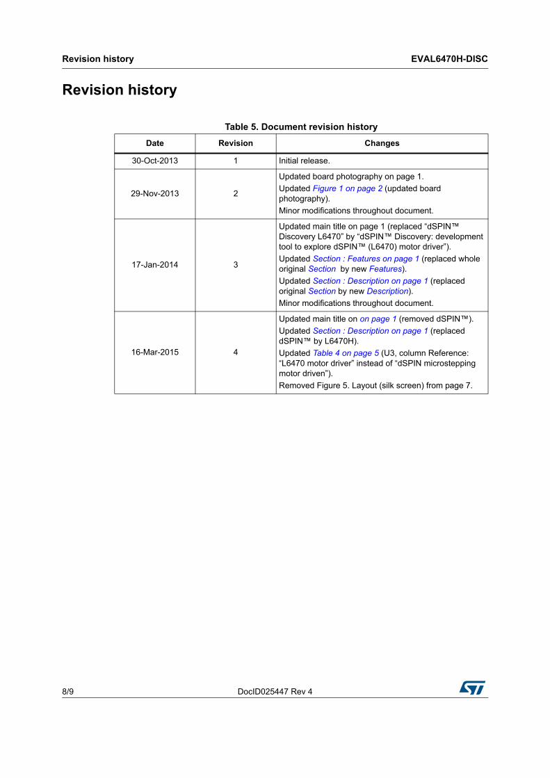
Revision history
Table 5. Document revision history
Date Revision Changes
30-Oct-2013 1 Initial release.
29-Nov-2013 2
Updated board photography on page 1.
Updated Figure 1 on page 2 (updated board photography).
Minor modifications throughout document.
17-Jan-2014 3
Updated main title on page 1 (replaced “dSPIN™ Discovery L6470” by “dSPIN™ Discovery: development tool to explore dSPIN™ (L6470) motor driver”).
Updated Section : Features on page 1 (replaced whole original Section by new Features).
Updated Section : Description on page 1 (replaced original Section by new Description).
Minor modifications throughout document.
16-Mar-2015 4
Updated main title on on page 1 (removed dSPIN™).
Updated Section : Description on page 1 (replaced dSPIN™ by L6470H).
Updated Table 4 on page 5 (U3, column Reference: “L6470 motor driver” instead of “dSPIN microstepping motor driven”).
Removed Figure 5. Layout (silk screen) from page 7.
DocID025447 Rev 4 9/9
EVAL6470H-DISC
9
IMPORTANT NOTICE – PLEASE READ CAREFULLY
STMicroelectronics NV and its subsidiaries (“ST”) reserve the right to make changes, corrections, enhancements, modifications, and improvements to ST products and/or to this document at any time without notice. Purchasers should obtain the latest relevant information on ST products before placing orders. ST products are sold pursuant to ST’s terms and conditions of sale in place at the time of order acknowledgement.
Purchasers are solely responsible for the choice, selection, and use of ST products and ST assumes no liability for application assistance or the design of Purchasers’ products.
No license, express or implied, to any intellectual property right is granted by ST herein.
Resale of ST products with provisions different from the information set forth herein shall void any warranty granted by ST for such product.
ST and the ST logo are trademarks of ST. All other product or service names are the property of their respective owners.
Information in this document supersedes and replaces information previously supplied in any prior versions of this document.
© 2015 STMicroelectronics – All rights reserved