l1402fx-usb - harbinger pro audio...l1402fx-usb 14-channel mixer l1402fx-usb owner's manual...
TRANSCRIPT
L1402FX-USB14-Channel Mixer
2 L1402FX-USB Owner's Manual
IMPORTANT SAFETY INSTRUCTIONSPlease keep this instruction manual for future reference and for the duration of owning the LvL mixer. Please carefully read and understand the instructions inside this owner’s manual before attempting to operate your new mixer.
This instruction manual includes essential safety information regarding the use and maintenance of the mixer. Take special care to heed all warning symbols and signs inside this manual and those printed on the mixer.
WARNING
TO PREVENT FIRE OR SHOCK HAZARD, DO NOT EXPOSE THE PRODUCT TO WATER/MOISTURE, NOR SHOULD YOU OPERATE THE PRODUCT NEAR ANY WATER SOURCE.
The exclamation point triangular symbol is intended to alert the user to the presence of important operating and maintenance(servicing) instructions in the user manual accompanying the product.
The lightning flash with an arrow triangular symbol is intended to alert the user to the presence of non-insulated “dangerous voltage” within the product’s enclosure that may be of sufficient magnitude to constitute a risk of electric shock.
WARNING
Handle the power supply cord with care.
Do not damage or deform it as it may cause electric shock or malfunction when used. Hold the plug attachment when removing from wall outlet. Do not pull on the power cord.
IMPORTANT SAFETY PRECAUTIONS
1. READ INSTRUCTIONS – All the safety and operating instructions should be read before this product is operated.
2. RETAIN INSTRUCTIONS – The safety and operating instructions should be retained for future reference.
3. HEED WARNINGS – All warnings on the product and in the operating instructions should be adhered to.
4. FOLLOW INSTRUCTIONS – All operating and use instructions should be followed.
5. DO NOT turn on the product module before connecting all other external devices.
6. WATER AND MOISTURE – Moisture can damage the product and can cause corrosion of electrical contacts. The system should not be used near water - for example, a bathtub, washbowl, kitchen sink, laundry tub, wet basement, or near a swimming pool, and the like.
7. HEAT – The product should be situated away from heat sources such as radiators, heat registers, stoves, or other sources (including amplifiers) that produce heat.
8. POWER SOURCES – This product should be operated only from the type of power source indicated on the rating label. If you are not sure of the type of power supply to your home, consult your product dealer or local power company.
9. GROUNDING OR POLARIZATION – Do not defeat the safety purpose of the polarization or grounding-type plug. The wide blade or the third prong is provided for your safety. If the provided plug does not fit your outlet, consult an electrician for replacement of the obsolete outlet. Do not defeat the safety purpose of the 3rd pin grounding prong.
10. POWER-CORD PROTECTION – Power supply cords should be routed so that they are not likely to be walked on or pinched by items placed upon or against them, paying particular attention to the cord in correspondence of plugs, convenience receptacles, and the point where they exit from the product.
11. CLEANING – The product should be cleaned only as recommended by the manufacturer. Clean by wiping with a dry cloth. Avoid getting water inside the product.
12. NON-USE PERIODS – The power cord of the product should be unplugged from the outlet when left unused for a long period of time.
13. OBJECT AND LIQUID ENTRY – Care should be taken so that objects do not fall and liquids are not spilled into the enclosure through openings.
14. DAMAGE REQUIRING SERVICE – The product should be serviced by qualified service personnel when:
A. The power supply cord or the plug has been damaged; or
B. Objects have fallen, or liquid has been spilled into the product; or
C. The product has been exposed to rain; or
D. The product does not appear to operate normally or exhibits a marked change in performance; or
E. The product has been dropped, or the enclosure damaged.
15. Keep the product out of extended or intense direct sun light.
16. No containers filled with any type of liquid should be placed on or near the product.
17. SERVICING – The user should not attempt any service to the product beyond that described in the operating instructions. All other servicing should be referred to qualified service personnel.
18. VENTILATION – Slots and openings in the product are provided for ventilation and to ensure reliable operation of the product and to protect it from overheating. These openings must not be blocked or covered. The openings should never be blocked by placing the product on a bed, sofa, rug, or other similar surface. This product should not be placed in a built-in installation such as a bookcase or rack.
19. ATTACHMENTS – Do not use attachments not recommended by the product manufacturer, as they may cause hazards.
20. ACCESSORIES – Do not place this product on an unstable cart, stand, tripod, bracket, or table. The product may fall, causing serious injury to a child or adult, and serious damage to the product. Use only with a cart, stand, tripod, bracket, or table recommended by the manufacturer, or sold with the product.
21. LIGHTNING – For added protection during a lightning storm, or when it is left unattended and unused for long periods of time, unplug it from the wall outlet. This will prevent damage to the product due to lightning and power-line surges.
22. REPLACEMENT PARTS – When replacement parts are required, be sure the service technician has used replacement parts specified by the manufacturer or have the same characteristics as the original part. Unauthorized substitutions may result in fire, electric shock, or other hazards.
23. SAFETY CHECK – Upon completion of any service or repairs to this product, ask the service technician to perform safety checks to determine that the product is in proper operating condition.
To prevent electric shock, do not use a polarized plug with an extension cord, receptacle or other outlet unless the blades can be fully inserted to prevent blade exposure.
THIS SYMBOL IS INTENDED TO ALERT THE USER TO THE PRESENCE OF IMPORTANT OPERATING AND MAINTENANCE (SERVICING) INSTRUCTIONS IN THE LITERATURE ACCOMPANYING THE UNIT.
APPARATUS SHALL NOT BE EXPOSED TO DRIPPING OR SPLASHING AND THAT NO OBJECTS FILLED WITH LIQUIDS, SUCH AS VASES, SHALL BE PLACED ON THE APPARATUS.
3
L1402FX-USB14-CHANNEL MIXER
L1402FX-USB Owner's Manual
TABLE OF CONTENTSQuick Start 4
What's on the Front and Back Panels 6
Input Types 8
Output Types 10
Effects Section 11
USB 12
Troubleshooting 12
Glossary of Terms 13
Cable Diagrams 14
Block Diagram 15
Mixer Specifications 16
Warranty/FCC Statements 17
WELCOME Congratulations on your recent purchase of a new Harbinger LvL Series mixer. They are the perfect choice for bands or individual musicians who are looking for great-sounding mixes, live performance durability and audio specs that studio users demand.
To get the most out of your new mixer, we suggest that you read through this entire manual at least once, then refer back to it as needed.
4 L1402FX-USB Owner's Manual
QUICK START
STUDIO QUICK START – PLUG IN A MICROPHONE AND HEAR IT THROUGH YOUR POWERED STUDIO MONITORS
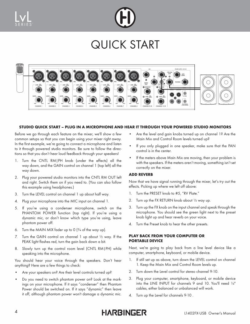
Before we go through each feature on the mixer, we'll show a few common setups so that you can begin using your mixer right away. In the first example, we’re going to connect a microphone and listen to it through powered studio monitors. Be sure to follow the direc-tions so that you don’t hear loud feedback through your speakers!
1. Turn the CNTL RM|PH knob (under the effects) all the way down, and the GAIN control on channel 1 (top left) all the way down.
2. Plug your powered studio monitors into the CNTL RM OUT left and right. Switch them on if you need to. (You can also follow this example using headphones.)
3. Turn the LEVEL control on channel 1 up about half way.
4. Plug your microphone into the MIC input on channel 1.
5. If you’re using a condenser microphone, switch on the PHANTOM POWER function (top right). If you’re using a dynamic mic, or don’t know which type you’re using, leave phantom power off.
6. Turn the MAIN MIX fader up to 0 (¾ of the way up).
7. Turn the GAIN control on channel 1 up about ½ way. If the PEAK light flashes red, turn the gain back down a bit.
8. Slowly turn up the control room level (CNTL RM|PH) while speaking into the microphone.
You should hear your voice through the speakers. Don’t hear anything? Here are a few things to check:
• Are your speakers on? Are their level controls turned up?
• Do you need to switch phantom power on? Look at the mark-ings on your microphone. If it says “condenser” then Phantom Power should be switched on. If it says “dynamic” then leave it off, although phantom power won't damage a dynamic mic.
• Are the level and gain knobs turned up on channel 1? Are the Main Mix and Control Room levels turned up?
• If you only plugged in one speaker, make sure that the PAN control is in the center.
• If the meters above Main Mix are moving, then your problem is with the speakers. If the meters aren’t moving, something isn’t set correctly on the mixer.
ADD REVERB
Now that we have signal running through the mixer, let’s try out the effects. Picking up where we left off above:
1. Turn the PRESET knob to #5, “RV Plate.”
2. Turn up the FX RETURN knob about ½ way up.
3. Turn up the FX knob on the input channel and speak through the microphone. You should see the green light next to the preset knob light up and hear reverb on your voice.
4. Turn the Preset knob to hear the other presets.
PLAY BACK FROM YOUR COMPUTER OR PORTABLE DEVICE
Next, we're going to play back from a line level device like a computer, smartphone, keyboard, or mobile device.
1. If still set up as above, turn down the LEVEL control on channel 1. Keep the Main Mix and Control Room levels up.
2. Turn down the Level control for stereo channel 9-10.
3. Plug your computer, smartphone, keyboard, or mobile device into the LINE INPUT for channels 9 and 10. You'll need ¼" cables, either balanced or unbalanced will work.
4. Turn up the Level for channels 9-10 .
5
L1402FX-USB14-CHANNEL MIXER
L1402FX-USB Owner's Manual
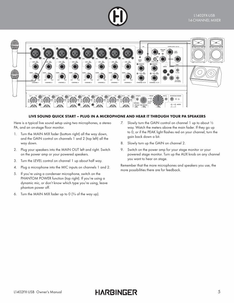
LIVE SOUND QUICK START – PLUG IN A MICROPHONE AND HEAR IT THROUGH YOUR PA SPEAKERS
Here is a typical live sound setup using two microphones, a stereo PA, and an on-stage floor monitor.
1. Turn the MAIN MIX fader (bottom right) all the way down, and the GAIN control on channels 1 and 2 (top left) all the way down.
2. Plug your speakers into the MAIN OUT left and right. Switch on the power amp or your powered speakers.
3. Turn the LEVEL control on channel 1 up about half way.
4. Plug a microphone into the MIC inputs on channels 1 and 2.
5. If you’re using a condenser microphone, switch on the PHANTOM POWER function (top right). If you’re using a dynamic mic, or don’t know which type you’re using, leave phantom power off.
6. Turn the MAIN MIX fader up to 0 (¾ of the way up).
7. Slowly turn the GAIN control on channel 1 up to about ½ way. Watch the meters above the main fader. If they go up to 0, or if the PEAK light flashes red on your channel, turn the gain back down a bit.
8. Slowly turn up the GAIN on channel 2.
9. Switch on the power amp for your stage monitor or your powered stage monitor. Turn up the AUX knob on any channel you want to hear on stage.
Remember that the more microphones and speakers you use, the more possibilities there are for feedback.
6 L1402FX-USB Owner's Manual
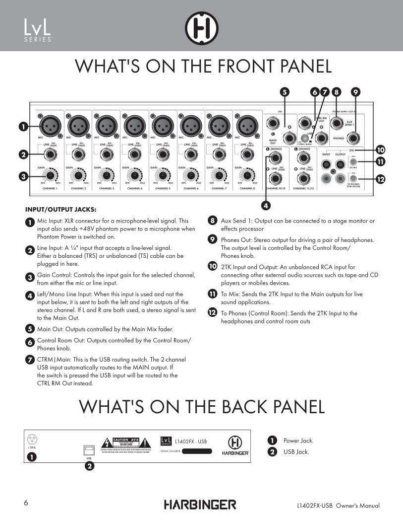
WHAT'S ON THE FRONT PANEL
INPUT/OUTPUT JACKS:
1 Mic Input: XLR connector for a microphone-level signal. This input also sends +48V phantom power to a microphone when Phantom Power is switched on.
2 Line Input: A ¼" input that accepts a line-level signal. Either a balanced (TRS) or unbalanced (TS) cable can be plugged in here.
3 Gain Control: Controls the input gain for the selected channel, from either the mic or line input.
4 Left/Mono Line Input: When this input is used and not the input below, it is sent to both the left and right outputs of the stereo channel. If L and R are both used, a stereo signal is sent to the Main Out.
5 Main Out: Outputs controlled by the Main Mix fader.
6 Control Room Out: Outputs controlled by the Control Room/ Phones knob.
7 CTRM|Main: This is the USB routing switch. The 2-channel USB input automatically routes to the MAIN output. If the switch is pressed the USB input will be routed to the CTRL RM Out instead.
Aux Send 1: Output can be connected to a stage monitor or effects processor
Phones Out: Stereo output for driving a pair of headphones. The output level is controlled by the Control Room/ Phones knob.
2TK Input and Output: An unbalanced RCA input for connecting other external audio sources such as tape and CD players or mobiles devices.
To Mix: Sends the 2TK Input to the Main outputs for live sound applications.
To Phones (Control Room): Sends the 2TK Input to the headphones and control room outs
9
1
2
3
4
7 85 6
10
11
10
11
12
8
12
9
WHAT'S ON THE BACK PANEL
1
21
2
Power Jack.
USB Jack.
7
L1402FX-USB14-CHANNEL MIXER
L1402FX-USB Owner's Manual
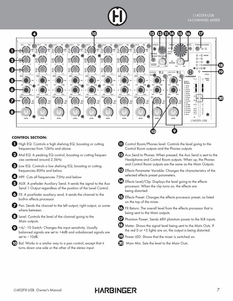
CONTROL SECTION:
1 High EQ: Controls a high shelving EQ, boosting or cutting frequencies from 12kHz and above
2 Mid EQ: A peaking EQ control, boosting or cutting frequen-cies centered around 2.5kHz
3 Low EQ: Controls a low shelving EQ, boosting or cutting frequencies 80Hz and below
4 HPF: Cuts all frequencies 75Hz and below
5 AUX: A prefader Auxiliary Send. It sends the signal to the Aux Send 1 Output regardless of the position of the Level Control.
FX: A post-fader auxiliary send. It sends the channel to the built-in effects processor.
Pan: Sends the channel to the left output, right output, or some-where between.
Level: Controls the level of the channel going to the Main outputs.
+4/–10 Switch: Changes the input sensitivity. Usually balanced signals are set to +4dB and unbalanced signals are set to –10dB.
Bal: Works in a similar way to a pan control, except that it turns down one side or the other of the stereo input.
11 Control Room/Phones level: Controls the level going to the Control Room outputs and the Phones outputs.
12 Aux Send to Phones: When pressed, the Aux Send is sent to the Headphone and Control Room outputs. When up, the Phones and Control Room outputs are the same as the Main Outputs.
13 Effects Parameter Variable: Changes the characteristics of the selected effects preset parameters.
14 Effects Level/Clip: Displays the level going to the effects processor. When the clip turns on, the effects are being distorted.
15 Effects Preset: Changes the effects processor preset, as listed on the top of the mixer.
16 FX Return: The overall level from the effects processor that is being sent to the Main outputs
17 Phantom Power: Sends 48V phantom power to the XLR inputs.
18 Meter: Shows the signal level being sent to the Main Outs. If the red 0 or +5 lights are on, the output is being distorted.
19 Power LED: Shows that the mixer is switched on.
20 Main Mix: Sets the level to the Main Outs.
10
1
2
3
6
151412 1310 11 164
7
9
18
19
5
6
7
8
8
9
10
17
20
8 L1402FX-USB Owner's Manual
INPUT TYPES This chapter will review the types of inputs on the L1402FX-USB mixer and explain each of their features.
CHANNELS 1-8: MIC/LINE INPUTS
MICROPHONE INPUT (MIC)
This XLR connector will accept virtually any professional microphone. It is designed for microphone level signals. If you have a device that plugs into the wall and has an XLR output (like a mic pre/channel strip, guitar multi effects processor, computer interface), you should get an XLR-to-¼" TRS cable and plug it into the line input (below).
Some microphones, mostly condenser mics, need phantom power to operate. Switch on phantom power on the right side of the mixer. If you're unsure if your mic needs phantom power, check the instruc-tions or the manufacturer's website for information. Phantom power should not hurt most microphones, except for very old or damaged ribbon microphones.
Use the microphone preamp's gain control (explained below) to bring the microphone up to a high enough level to use with the mixer.
LINE INPUT (LINE)
This ¼" input is designed for line-level signals. It accepts either balanced (TRS) or unbalanced (TS) cables. The level of this input is also controlled by the gain control, explained below.
Do not use both the microphone and line inputs on the same channel. The mixer will distort and the noise level will go up.
The line input is not designed to accept an instrument-level signal, such as the output from an electric or acoustic guitar or bass. If you want to plug your instrument into the mixer, we suggest a direct box (also called a DI box). Plug your instrument into the direct box, then plug the output of the direct box into the microphone input of the mixer.
GAIN
Gain controls the level of the microphone or line level signal plugged into the mixer. If the gain is set too low, the output signal will be noisy when you turn it up at the level control. If gain is set too high, it will distort.
For best performance, set the gain while looking at the meters. Turn the Level control so that it's facing straight up. Then turn the gain up until you see the first or second lights on the meter. Don't set it too high – although you might not hear distortion when playing by itself, when all of the channels are playing at that level they may add together and distort the mixer.
Sidebar: "Why are there two volume controls?"
The Gain and Level controls work together to get the best performance out of the mixer. A quiet signal may need more gain than a loud guitar amp going into a sensitive
microphone. Set the gain so that the level on each channel is roughly the same, then use the Level controls to set the balance that you want in your mix.
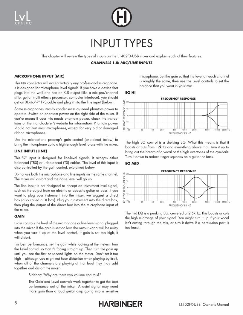
EQ HI
The high EQ control is a shelving EQ. What this means is that it boosts or cuts from 12kHz and everything above that. Turn it up to bring out the breath of a vocal or the high overtones of the cymbals. Turn it down to reduce finger squeaks on a guitar or bass.
EQ MID
The mid EQ is a peaking EQ, centered at 2.5kHz. This boosts or cuts the high midrange of your signal. You might turn it up if your vocal isn't cutting through the mix, or turn it down if a percussion part is too harsh.
FREQUENCY IN HZ
FREQUENCY RESPONSE
RELA
TIVE
RES
PON
SE IN
dB
FREQUENCY IN HZ
FREQUENCY RESPONSE
RELA
TIVE
RES
PON
SE IN
dB
9
L1402FX-USB14-CHANNEL MIXER
L1402FX-USB Owner's Manual
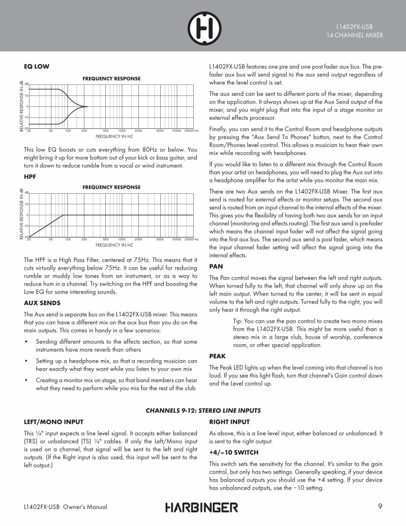
EQ LOW
This low EQ boosts or cuts everything from 80Hz or below. You might bring it up for more bottom out of your kick or bass guitar, and turn it down to reduce rumble from a vocal or wind instrument.
HPF
The HPF is a High Pass Filter, centered at 75Hz. This means that it cuts virtually everything below 75Hz. It can be useful for reducing rumble or muddy low tones from an instrument, or as a way to reduce hum in a channel. Try switching on the HPF and boosting the Low EQ for some interesting sounds.
AUX SENDS
The Aux send is separate bus on the L1402FX-USB mixer. This means that you can have a different mix on the aux bus than you do on the main outputs. This comes in handy in a few scenarios:
• Sending different amounts to the effects section, so that some instruments have more reverb than others
• Setting up a headphone mix, so that a recording musician can hear exactly what they want while you listen to your own mix
• Creating a monitor mix on stage, so that band members can hear what they need to perform while you mix for the rest of the club
L1402FX-USB features one pre and one post fader aux bus. The pre-fader aux bus will send signal to the aux send output regardless of where the level control is set.
The aux send can be sent to different parts of the mixer, depending on the application. It always shows up at the Aux Send output of the mixer, and you might plug that into the input of a stage monitor or external effects processor.
Finally, you can send it to the Control Room and headphone outputs by pressing the "Aux Send To Phones" button, next to the Control Room/Phones level control. This allows a musician to hear their own mix while recording with headphones.
If you would like to listen to a different mix through the Control Room than your artist on headphones, you will need to plug the Aux out into a headphone amplifier for the artist while you monitor the main mix.
There are two Aux sends on the L1402FX-USB Mixer. The first aux send is routed for external effects or monitor setups. The second aux send is routed from an input channel to the internal effects of the mixer. This gives you the flexibility of having both two aux sends for an input channel (monitoring and effects routing). The first aux send is pre-fader which means the channel input fader will not affect the signal going into the first aux bus. The second aux send is post fader, which means the input channel fader setting will affect the signal going into the internal effects.
PAN
The Pan control moves the signal between the left and right outputs. When turned fully to the left, that channel will only show up on the left main output. When turned to the center, it will be sent in equal volume to the left and right outputs. Turned fully to the right, you will only hear it through the right output.
Tip: You can use the pan control to create two mono mixes from the L1402FX-USB. This might be more useful than a stereo mix in a large club, house of worship, conference room, or other special application.
PEAK
The Peak LED lights up when the level coming into that channel is too loud. If you see this light flash, turn that channel's Gain control down and the Level control up.
CHANNELS 9-12: STEREO LINE INPUTS
LEFT/MONO INPUT
This ¼" input expects a line level signal. It accepts either balanced (TRS) or unbalanced (TS) ¼" cables. If only the Left/Mono input is used on a channel, that signal will be sent to the left and right outputs. (If the Right input is also used, this input will be sent to the left output.)
RIGHT INPUT
As above, this is a line level input, either balanced or unbalanced. It is sent to the right output.
+4/–10 SWITCH
This switch sets the sensitivity for the channel. It's similar to the gain control, but only has two settings. Generally speaking, if your device has balanced outputs you should use the +4 setting. If your device has unbalanced outputs, use the –10 setting.
FREQUENCY IN HZ
FREQUENCY RESPONSE
RELA
TIVE
RES
PON
SE IN
dB
FREQUENCY IN HZ
FREQUENCY RESPONSE
RELA
TIVE
RES
PON
SE IN
dB
10 L1402FX-USB Owner's Manual
AUX SEND
This sends the channel to the aux bus. See the previous section for more information.
BALANCE (BAL)
The Balance knob has a similar effect to the pan control explained in the previous section. But the Balance control just turns down one input or the other. As you turn Balance to the right, the signal coming into the Left/Mono input gets softer. This allows you to control the panning in your mix without collapsing the stereo width of the input.
LEVEL
This controls the level of the channel going to the Main Outs. See the previous section for more information.
2TK INPUT
The 2TK Inputs are a pair of unbalanced RCA phono line inputs. They can be used for a variety of applications:
• Monitoring a mixdown recorder. Since these inputs aren't sent to the Main Outputs, there is no chance of a feedback loop.
• Playing an MP3 player through the PA between band sets, muting all microphones
• Sending a signal to the headphone outputs but not to the main outputs. You might plug a set of outputs from a computer inter-face into these inputs, so that the metronome click can be sent to the headphones but not the main out.
There are two buttons that control where these inputs are heard. One is To Mix and the other is To Phones (Ctrl Room.)
When TO MIX is switched on, all of the inputs are muted except for the 2TK input. All that you will hear from the L/R outputs is what is playing into the 2TK input. You might use this in the example above to play audio from a mobile device to the PA between sets.
Pressing TO PHONES/CONTROL ROOM means that only the 2TK input is heard through the Control Room and Phones outputs. This is useful if you are recording the mix and only want to hear what is coming back from the recorder. This ensures that the recorder is getting the mix that you expect to hear. It also allows you to monitor the recorder output without creating a feedback loop in the speakers.
OUTPUT TYPES This chapter explains each of the outputs on the Harbinger L1402FX-USB mixer and their level controls.
MAIN OUTS
The Main Outs are line outputs. They will work with either balanced or unbalanced cables. The Main Mix fader controls the level of the Main Outputs. You might plug the main outs into a PA amplifier or a mixdown recorder.
All of the channels should show up at the Main outputs. If they don't, make sure that the "2TK to Mix" button isn't pushed.
CONTROL ROOM OUTPUTS (CTRL RM OUT)
The Control Room Outputs are a separate set of outputs for the mixer. In a home studio, you might plug these into a set of powered studio monitors. The Ctrl Rm|Ph knob controls the level going to the control room outputs (and the headphones.)
There are three sources that can be sent to the Control Room Outputs. Usually, you listen to the same mix that's coming out of the Main Outs. If the 2TK to Phones (Ctrl Room) button is pressed, only the 2TK input will be heard through the Control Room outputs.
If the Aux to Phones (Ctrl Rm) is pressed down, the aux send will be heard through the Control Room outputs. This can be useful when preparing a headphone mix for an artist.
PHONES
This is a headphone-level output. It is designed to drive a pair of headphones with a balanced ¼" connector. If your headphones have a 1/8" stereo jack, you will need an adapter to plug them into the mixer (included with most professional headphones.)
Note that the headphones and the control room outputs are linked – both the mix and level. If you press 2TK to Phones (Ctrl Room), the 2TK input will be sent to both the control room outs and the head-phones. If you turn the control room level all the way down, there will be no signal in the headphones.
AUX SEND
This jack sends the aux bus out of the mixer. Turn up the Aux knob on any channel to send it to the Aux Send output. See page 9 for more information about the Aux Send.
2TK OUTPUT
This is a pair of unbalanced line level outputs. They are just a copy of the Main Outputs. If you turn the Main Mix fader down, the level is also reduced here.
11
L1402FX-USB14-CHANNEL MIXER
L1402FX-USB Owner's Manual
EFFECTS SECTION The Harbinger L1402FX-USB includes a great-sounding digital effects processor. This chapter explains how to use it.
PRESET
The L1402FX-USB Effects Processor has 16 presets. Each of these is a different effect type. The preset names are listed on the top of the mixer. They are explained in further detail below.
VARIABLE PARAMETER
This knob changes the character of the effect depending on the effect type. It either changes the length of a reverb, the feedback/repeat amount of a delay, or the depth of a modulation effect. See the preset descriptions below for more information on how this control works.
TAP
On effects presets with delay, press this button twice to set the delay time. This is useful for setting the delay time in tempo with the music. If you want a quarter note delay, press the Tap button on two successive beats of the music and the delay time will jump to that tempo.
SIGNAL/CLIP LEDS
These show the level going to the input of the effects processor. When you send a channel to the effects processor, using the FX knob, you should see the green Sgn light turn on. If the level gets too high, you'll see the red Clip LED turn on. If this happens, turn down the Aux 2 Send knobs on each channel to avoid distorting the effects.
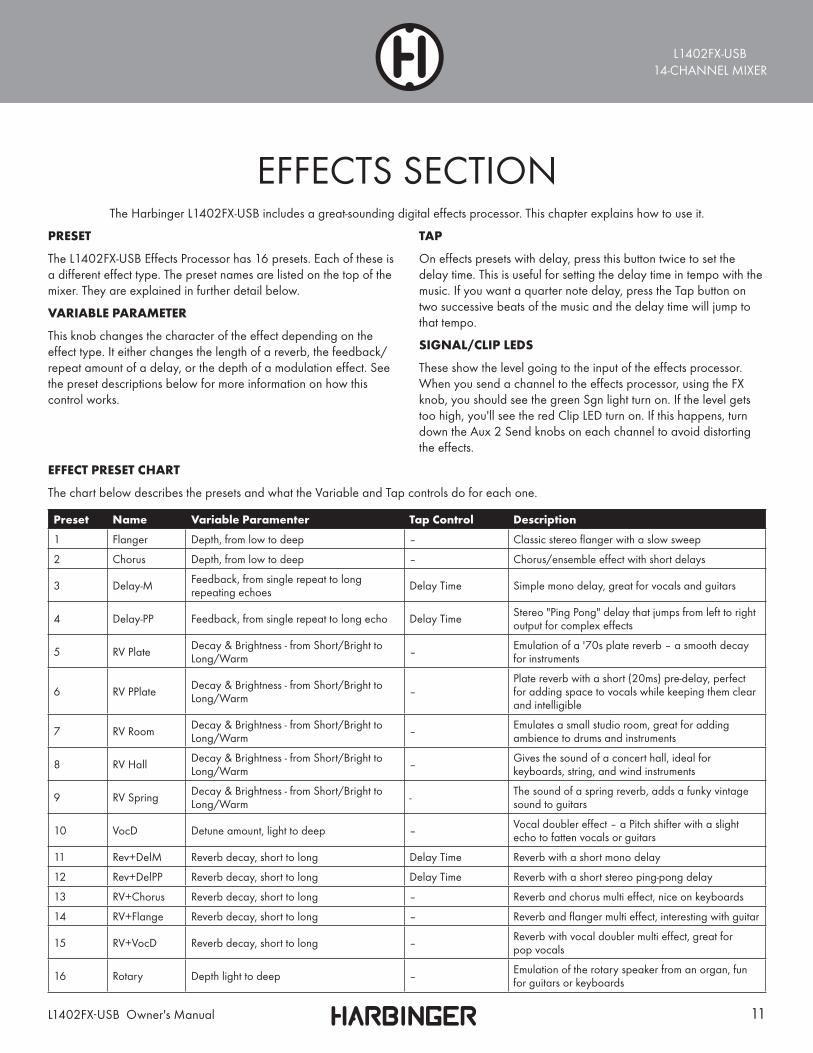
EFFECT PRESET CHART
The chart below describes the presets and what the Variable and Tap controls do for each one.
Preset Name Variable Paramenter Tap Control Description
1 Flanger Depth, from low to deep – Classic stereo flanger with a slow sweep
2 Chorus Depth, from low to deep – Chorus/ensemble effect with short delays
3 Delay-M Feedback, from single repeat to long repeating echoes Delay Time Simple mono delay, great for vocals and guitars
4 Delay-PP Feedback, from single repeat to long echo Delay Time Stereo "Ping Pong" delay that jumps from left to right output for complex effects
5 RV Plate Decay & Brightness - from Short/Bright to Long/Warm – Emulation of a '70s plate reverb – a smooth decay
for instruments
6 RV PPlate Decay & Brightness - from Short/Bright to Long/Warm –
Plate reverb with a short (20ms) pre-delay, perfect for adding space to vocals while keeping them clear and intelligible
7 RV Room Decay & Brightness - from Short/Bright to Long/Warm – Emulates a small studio room, great for adding
ambience to drums and instruments
8 RV Hall Decay & Brightness - from Short/Bright to Long/Warm – Gives the sound of a concert hall, ideal for
keyboards, string, and wind instruments
9 RV Spring Decay & Brightness - from Short/Bright to Long/Warm - The sound of a spring reverb, adds a funky vintage
sound to guitars
10 VocD Detune amount, light to deep – Vocal doubler effect – a Pitch shifter with a slight echo to fatten vocals or guitars
11 Rev+DelM Reverb decay, short to long Delay Time Reverb with a short mono delay
12 Rev+DelPP Reverb decay, short to long Delay Time Reverb with a short stereo ping-pong delay
13 RV+Chorus Reverb decay, short to long – Reverb and chorus multi effect, nice on keyboards
14 RV+Flange Reverb decay, short to long – Reverb and flanger multi effect, interesting with guitar
15 RV+VocD Reverb decay, short to long – Reverb with vocal doubler multi effect, great for pop vocals
16 Rotary Depth light to deep – Emulation of the rotary speaker from an organ, fun for guitars or keyboards
12 L1402FX-USB Owner's Manual
USBRecording and playing back audio through USB
TO PLAYBACK AUDIO
1. Connect your computer to the mixer with a USB cable. Your computer should see the mixer as a device labeled "Samsung UC Audio".
2. Select the mixer to playback audio from your system control panel.
3. Playback audio from your application.
4. Make sure the CTRM/MAIN button is down near the Jacks that say CTRL RM OUT.
5. The audio is routing to the main outputs through Aux inputs, which means the volume control is controlled by the main fader if the "To Mix" button is depressed (next to the RCA jacks for AUX). The same case for Control Room.
• Are the Gain and Level knobs turned up?
• Is the Main Mix fader turned up?
• Is the 2TK to Mix, 2TK to Phones, or Aux to Phones button pressed in?
• If the mic needs phantom power, is the PHANTOM POWER turned on? (Try it if you aren't sure.)
• Try a different microphone cable and/or microphone.
• Check the power connections, your power strip, extension cords, etc.
You can hear everything, but it's very noisy.
• Are all of the level controls turned up very high? Try turning those down and the gain controls up.
• Turn down the FX return. If that was the problem, try sending more signal to the effects by turning all of the Aux knobs up.
• Try turning down channels one at a time. If there is one channel
that is contributing most of the noise, try fixing that at the source.
You can see level on the meters, but can't hear anything through the control room speakers.
• Is the Aux to Phones/Control Room or 2TK to Phones/Control Room button pressed in?
• Are the monitors switched on?
• If only one output is working, try switching the left and right outputs. If the same channel isn't working, the problem is with the speaker.
You turned up the FX Return knob, but can't hear the effects.
• Are you sending enough level to light the Signal LED next to the preset knob? If not then turn up the Aux knob(s).
•Are you listening to the Aux to Phones/Control Room by mistake?
•Try a different Preset or turn the Variable knob.
TO RECORD AUDIO
1. Connect your computer to the mixer with a USB cable. Your computer should see the mixer as a device labeled "Samsung UC Audio".
2. Select the mixer playback and record audio from your system control panel.
3. Setup your mixer to have audio coming in as you normally would.
4. Start up your DAW application on your computer.
5. Make sure your DAW application is setup to receive audio from the "Samsung UC Audio" (L1402FX-USB mixer)
6. Create an audio track on your mixer and enable it to record. To avoid a feedback you can either switch the "To Mix" button to be in the up position or disable the monitoring function in your DAW program on the track you are recording to.
7. Perform your audio on the mixer and record the track on your DAW application.
8. After recording you can play back the track from your computer to the mixer to hear the playback. Be sure to turn on the "To Mix" or "To Phones (CTRL ROOM)" button to hear the audio playback.
TROUBLESHOOTING In this chapter, we'll discuss common problems and their solutions, as well as who to contact if things go wrong with your mixer.
TROUBLESHOOTING MATRIX
A microphone is plugged in, but you don't see any level on the main meters.
13
L1402FX-USB14-CHANNEL MIXER
L1402FX-USB Owner's Manual
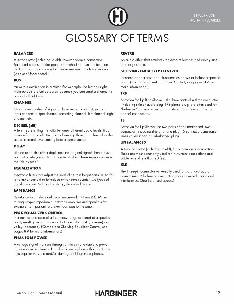
GLOSSARY OF TERMS BALANCED
A 3-conductor (including shield), low-impedance connection. Balanced cables are the preferred method for hum-free intercon-nection of a sound system for their noise-rejection characteristics. (Also see Unbalanced.)
BUS
An output destination in a mixer. For example, the left and right main outputs are called buses, because you can send a channel to one or both of them.
CHANNEL
One of any number of signal paths in an audio circuit, such as input channel, output channel, recording channel, left channel, right channel, etc.
DECIBEL (dB)A term representing the ratio between different audio levels. It can either refer to the electrical signal running through a channel or the acoustic sound level coming from a sound source.
DELAY
Like an echo, this effect duplicates the original signal, then plays it back at a rate you control. The rate at which these repeats occur is the “delay time.”
EQUALIZATION
Electronic filters that adjust the level of certain frequencies. Used for tone enhancement or to reduce extraneous sounds. Two types of EQ shapes are Peak and Shelving, described below.
IMPEDANCE
Resistance in an electrical circuit measured in Ohms (Ω). Main-taining proper impedance (between amplifier and speakers for example) is important to prevent damage to the amp.
PEAK EQUALIZER CONTROL Increase or decrease of a frequency range centered at a specific point, resulting in an EQ curve that looks like a hill (increase) or a valley (decrease). (Compare to Shelving Equalizer Control; see pages 8-9 for more information.)
PHANTOM POWER
A voltage signal that runs through a microphone cable to power condenser microphones. Harmless to microphones that don't need it, except for very old and/or damaged ribbon microphones.
REVERB
An audio effect that emulates the echo reflections and decay time of a large space.
SHELVING EQUALIZER CONTROL
Increase or decrease of all frequencies above or below a specific point. (Compare to Peak Equalizer Control; see pages 8-9 for more information.)
TRS
Acronym for Tip-Ring-Sleeve — the three parts of a three-conductor (including shield) audio plug. TRS phone plugs are often used for “balanced” mono connections, or stereo "unbalanced" (head-phone) connections.
TS
Acronym for Tip-Sleeve, the two parts of an unbalanced, two-conductor (including shield) phone plug. TS connectors are some-times called mono or unbalanced plugs.
UNBALANCED
A two-conductor (including shield), high-impedance connection. These are most commonly used for instrument connections and cable runs of less than 20 feet.
XLR
The three-pin connector universally used for balanced audio connections. A balanced connection reduces outside noise and interference. (See Balanced above.)
14 L1402FX-USB Owner's Manual
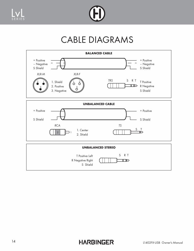
BALANCED CABLE
XLR-M
+ Positive
+ Positive
1. Shield
1. Center
T Positive Left S
S
R
R
T
T T Positive
+ Positive
+ Positive
– Negative
2. Positive
2. Shield
R Negative Right
2
2
11
1
2
3 3 R Negative
– NegativeS Shield
S Shield
3. Negative
S Shield
S Shield
S Shield
S Shield
XLR-F
RCA
TRS
TS
UNBALANCED CABLE
UNBALANCED STEREO
CABLE DIAGRAMS
S T
15
L1402FX-USB14-CHANNEL MIXER
L1402FX-USB Owner's Manual
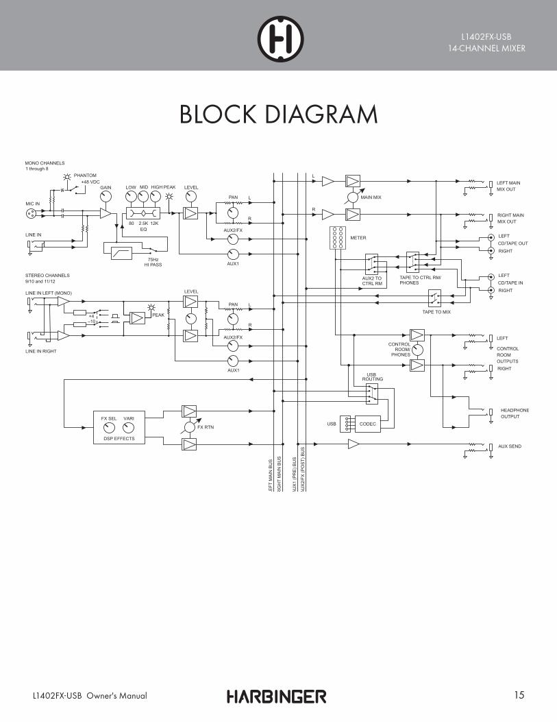
BLOCK DIAGRAM
16 L1402FX-USB Owner's Manual
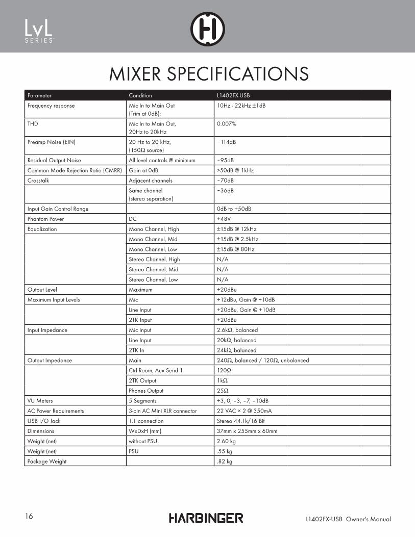
MIXER SPECIFICATIONSParameter Condition L1402FX-USB
Frequency response Mic In to Main Out (Trim at 0dB):
10Hz - 22kHz ±1dB
THD Mic In to Main Out, 20Hz to 20kHz
0.007%
Preamp Noise (EIN) 20 Hz to 20 kHz, (150Ω source)
–114dB
Residual Output Noise All level controls @ minimum –95dB
Common Mode Rejection Ratio (CMRR) Gain at 0dB >50dB @ 1kHz
Crosstalk Adjacent channels –70dB
Same channel (stereo separation)
–36dB
Input Gain Control Range 0dB to +50dB
Phantom Power DC +48V
Equalization Mono Channel, High ±15dB @ 12kHz
Mono Channel, Mid ±15dB @ 2.5kHz
Mono Channel, Low ±15dB @ 80Hz
Stereo Channel, High N/A
Stereo Channel, Mid N/A
Stereo Channel, Low N/A
Output Level Maximum +20dBu
Maximum Input Levels Mic +12dBu, Gain @ +10dB
Line Input +20dBu, Gain @ +10dB
2TK Input +20dBu
Input Impedance Mic Input 2.6kΩ, balanced
Line Input 20kΩ, balanced
2TK In 24kΩ, balanced
Output Impedance Main 240Ω, balanced / 120Ω, unbalanced
Ctrl Room, Aux Send 1 120Ω
2TK Output 1kΩ
Phones Output 25Ω
VU Meters 5 Segments +3, 0, –3, –7, –10dB
AC Power Requirements 3-pin AC Mini XLR connector 22 VAC × 2 @ 350mA
USB I/O Jack 1.1 connection Stereo 44.1k/16 Bit
Dimensions WxDxH (mm) 37mm x 255mm x 60mm
Weight (net) without PSU 2.60 kg
Weight (net) PSU .55 kg
Package Weight .82 kg

WARRANTYHave a question about service, warranty or parts?
Call 888-286-1809 (Toll Free)
2 YEAR HARBINGER LIMITED WARRANTY
Harbinger provides, to the original purchaser, a two (2) year limited warranty on materials and workmanship on all Harbinger mixers from the date of purchase.
For warranty support, please visit our website at www.Harbinger ProAudio.com, or contact our Support Team at 888-286-1809 for assistance. Harbinger will repair or replace the unit at Harbinger’s discretion.
This warranty does not cover service or parts to repair damage caused by neglect, abuse, normal wear and tear and cosmetic appearance to the chassis not directly attributed to defects in materials or workmanship. Also excluded from coverage are damages caused directly or indirectly due to any service, repair(s), or modifications of the chassis, which has not been authorized or approved by Harbinger. This two (2) year warranty does not cover service or parts to repair damage caused by accident, disaster, misuse, abuse, negligence, inadequate packing or inadequate shipping procedures.
The sole and exclusive remedy of the foregoing limited warranty shall be limited to the repair or replacement of any defective or non-conforming component. All warranties including, but not limited to, the express
warranty and the implied warranties of merchantability and fitness for a particular purpose are limited to the two (2) year warranty period. Some states do not allow limitation on how long an implied warranty lasts, so the above limitation may not apply to you. There are no express warranties beyond those stated here. In the event that applicable law does not allow the limitation of the duration of the implied warranties to the warranty period, then the duration of the implied warranties shall be limited to as long as is provided by applicable law. No warranties apply after that period.
Retailer and manufacturer shall not be liable for damages based upon inconvenience, loss of use of product, loss of time, interrupted operation or commercial loss or any other incidental or consequential damages including but not limited to lost profits, downtime, goodwill, damage to or replacement of equipment and property, and any costs of recovering, reprogramming, or reproducing any program or data stored in equipment that is used with Harbinger products. This guarantee gives you specific legal rights; you may have other legal rights, which vary from state to state.
Harbinger P.O. Box 5111, Thousand Oaks, CA 91359-5111
All trademarks and registered trademarks mentioned herein are recognized as the property of their respective holders.
So we may serve you better, please register on-line at www.HarbingerProAudio.com
FCC STATEMENTS1. Caution: Changes or modifications to this unit not expressly approved by the party
responsible for compliance could void the user’s authority to operate the equipment.2. Note: This equipment has been tested and found to comply with the limits for
a Class B digital device, pursuant to Part 15 of the FCC Rules. These limits are designed to provide reasonable protection against harmful interference in a residential installation. This equipment generate, uses, and can radiate radio frequency energy and, if not installed and used in accordance with the instructions, may cause harmful interference to radio communications. However, there is no guarantee that interference will not occur in a particular installation. If this equipment does cause harmful interference to radio or television reception, which
can be determined by turning the equipment off and on, the user is encouraged to try to correct the interference by one or more of the following measures:• Reorient or relocate the receiving antenna
• Increase the separation between the equipment and receiver
• Connect the equipment into an outlet on a circuit different from that to which the receiver is connected
• Consult the dealer or an experienced radio/TV technician for help