l000541-b - remeha€¦ · remasol en solar hot water calorifer 200se-2s - 300se-2s l000541-b...
TRANSCRIPT

RemaSol EN
Solar hot water calorifer
200SE-2S - 300SE-2S
L000541-B
Installation andService Manual
7607575-05

Declaration of conformity [The device complies with the standard type described inthe EG declaration of conformity. It was manufactured andcommissioned in accordance with European directives.The original declaration of conformity is available from themanufacturer.
M003220-A

Contents
1 Safety instructions .....................................................................................61.1 Safety instructions ...............................................6
1.2 Recommendations ................................................8
1.3 Liabilities ...............................................................91.3.1 Manufacturer’s liability .............................................91.3.2 Installer’s liability ...................................................10
2 About this manual ....................................................................................112.1 Symbols used .....................................................11
2.1.1 Symbols used in the manual .................................112.1.2 Symbols used on the equipment ...........................11
2.2 Abbreviations ......................................................11
3 Technical description ..............................................................................123.1 Homologations ....................................................12
3.1.1 Certifications .........................................................123.1.2 Directive 97/23/EC ................................................12
3.2 General description ............................................12
3.3 Main parts ............................................................133.3.1 Solar domestic hot water calorifier ........................133.3.2 Solar station ..........................................................143.3.3 Solar regulator .......................................................14
3.4 Operating principle .............................................143.4.1 General principle ...................................................153.4.2 Protection against overheating on the solar
circuit .....................................................................16
3.5 Technical specifications ....................................163.5.1 Solar domestic hot water calorifier ........................163.5.2 Sensor characteristics ...........................................173.5.3 Solar regulator .......................................................173.5.4 Solar station ..........................................................18
4 Installation ................................................................................................194.1 Regulations governing installation ...................19
4.2 Package list .........................................................194.2.1 Standard delivery ..................................................19
26/04/2016 - 7607575-05 1

4.3 Choice of the location ........................................204.3.1 Type plate .............................................................204.3.2 Positioning of the appliance ..................................204.3.3 Main dimensions ...................................................21
4.4 Positioning the appliance ..................................22
4.5 Levelling ..............................................................22
4.6 Installing the temperature sensors ...................22
4.7 Hydraulic installation diagrams ........................234.7.1 Boiler for heating only (Output <45 kW) +
200/300SE-2S ......................................................234.7.2 Combi boiler + 200/300SE-2S .............................244.7.3 Combi boiler + Additional heating (Output <45 kW) +
200/300SE-2S ......................................................25
4.8 Safety unit ...........................................................26
4.9 Hydraulic connections .......................................274.9.1 Primary solar circuit ...............................................274.9.2 Primary heating circuit ...........................................314.9.3 Connecting the calorifer to the domestic water circuit
(secondary circuit) .................................................31
4.10 Electrical connections ........................................334.10.1 Recommendations ................................................334.10.2 Connecting the solar control system .....................344.10.3 Electrical diagram ..................................................344.10.4 Connecting the resistor .........................................364.10.5 Connecting the circulation pump ...........................37
4.11 Filling the DHW calorifer ....................................374.11.1 Drinking water quality ............................................37
4.12 Filling the primary solar circuit .........................384.12.1 Flowmeter .............................................................384.12.2 Anti-thermosiphon valve ........................................394.12.3 Filling the primary solar circuit ...............................39
4.13 Filling the heating circuit ...................................43
5 Commissioning ........................................................................................445.1 Control panels .....................................................44
5.1.1 Description of the keys ..........................................445.1.2 Description of the display ......................................44
5.2 Check points before commissioning ................465.2.1 Domestic hot water calorifer ..................................465.2.2 Primary solar circuit ...............................................465.2.3 Primary heating circuit ...........................................465.2.4 Electrical connection .............................................46
Contents
26/04/2016 - 7607575-05 2

5.3 Commissioning procedure ................................475.3.1 Secondary circuit (domestic water) .......................475.3.2 Primary solar circuit ...............................................47
5.4 Reading out measured values ...........................485.4.1 Resetting the values to zero ..................................48
5.5 Installer parameters ............................................495.5.1 Modifying the installer parameters ........................495.5.2 List of the parameters ...........................................495.5.3 Description of the installer parameters ..................51
6 Checking and maintenance .....................................................................566.1 General instructions ...........................................56
6.2 Safety valve or safety unit .................................56
6.3 Cleaning the casing material .............................56
6.4 Checking the magnesium anode .......................56
6.5 Descaling .............................................................57
6.6 Removing and remounting the inspectionhatches ................................................................576.6.1 Removing the inspection hatches .........................576.6.2 Remounting the inspection hatches ......................58
6.7 Inspection and maintenance of the solarcircuit ...................................................................596.7.1 Maintenance operations to be performed .............596.7.2 Adding heat transporting fluid ...............................59
6.8 Maintenance form ...............................................60
6.9 Installation report ...............................................62
7 Troubleshooting .......................................................................................647.1 Electricity supply ................................................64
7.2 Sensor fault .........................................................64
7.3 Incidents and solutions ......................................65
8 Spare parts ................................................................................................668.1 General ................................................................66
8.2 Spare parts ..........................................................678.2.1 Domestic hot water tanks ......................................678.2.2 Solar station ..........................................................698.2.3 Electric heating resistance For 200/400) only .......71
26/04/2016 - 7607575-05 3

9 Appendix – Information on the Ecodesign and Energy LabellingDirectives ..................................................................................................72
Contents
26/04/2016 - 7607575-05 4

26/04/2016 - 7607575-05 5

1 Safety instructions
1.1 Safety instructions
DANGER
This appliance can be used by children agedfrom 8 years and above and persons withreduced physical, sensory or mental capabilitiesor lack of experience and knowledge if they havebeen given supervision or instruction concerninguse of the appliance in a safe way andunderstand the hazards involved. Children shallnot play with the appliance. Cleaning and usermaintenance shall not be made by childrenwithout supervision.
CAUTION
1. Turn off the domestic cold water inlet.2. Open a hot water tap on the installation.3. Open a safety unit valve.4. When the water stops flowing, the appliance
has been drained.
1. Safety instructions 200SE-2S - 300SE-2S
6 26/04/2016 - 7607575-05
CAUTION
Pressure limiter device
4 The pressure limiter device (safety valve orsafety unit) must be operated regularly inorder to clear out any limescale deposits andensure that it is not blocked.
4 The pressure limiter device must beconnected to a discharge pipe.
4 As water may flow from the discharge pipe,it must be kept open to the air, in a frost-freeenvironment, in a continuous downwardgradient.
For the type, characteristics and connection ofthe pressure limiter device, please refer to thesection entitled Connecting the domestic hotwater tank to the drinking water network in theinstallation and service manual for the domestichot water tank.
The user guide and the installation manual canalso be found on our internet site.
CAUTION
Allowance must be made for a means ofdisconnection in the fixed pipes in accordancewith the regulations on installations.
CAUTION
If a power cord is provided with the applianceand it turns out to be damaged, it must bereplaced by the manufacturer, its after salesservice or persons with similar qualifications inorder to obviate any danger.
200SE-2S - 300SE-2S 1. Safety instructions
26/04/2016 - 7607575-05 7

CAUTION
Respect the maximum water inlet pressure toensure correct operation of the appliance,referring to the chapter "TechnicalSpecifications".
CAUTION
Before any work, switch off the mains supply tothe appliance.
CAUTION
In order to limit the risk of being scalded, theinstallation of a thermostatic mixing valve on thedomestic hot water flow piping is compulsory.
1.2 Recommendations
CAUTION
Do not neglect to service the appliance. Servicethe appliance regularly to ensure that it operatescorrectly.
WARNING
Only qualified professionals are authorised towork on the appliance and the installation.
WARNING
4 The heating water and the water-propylene-glycol mixture must not come into contactwith the domestic hot water.
4 The domestic hot water must not circulatethrough an exchanger.
4 Solar installations can be protected againstlighting and must be earthed or connectedto an equipotential connection.
To take advantage of the guarantee, no modificationsmust be made to the appliance. Only remove the coversfor maintenance and breakdown repair operations and putthe covers back in place after the maintenance andbreakdown repair operations.Instructions stickers
1. Safety instructions 200SE-2S - 300SE-2S
8 26/04/2016 - 7607575-05

The instructions and warnings affixed to the appliancemust never be removed or covered and must remainlegible during the entire lifespan of the appliance.Immediately replace damaged or illegible instructions andwarning stickers.
WARNING
Never cut the power to the solar control system,even during extended absences. The controlsystem protects the installation againstoverheating in summer when it is running.
WARNING
Do not modify the control system parametersunless fully conversant with them.
During extended absences, we recommend lowering theset point temperature in the solar DHW calorifier to 45°C.When the user is present, the set point must be set to60°C.
1.3 Liabilities
1.3.1. Manufacturer’s liability
Our products are manufactured in compliance with therequirements of the various applicable European
Directives. They are therefore delivered with [ markingand all relevant documentation.In the interest of customers, we are continuouslyendeavouring to make improvements in product quality.All the specifications stated in this document are thereforesubject to change without notice.
Our liability as the manufacturer may not be invoked in thefollowing cases:4Failure to abide by the instructions on using the
appliance.4Faulty or insufficient maintenance of the appliance.4Failure to abide by the instructions on installing the
appliance.
200SE-2S - 300SE-2S 1. Safety instructions
26/04/2016 - 7607575-05 9

1.3.2. Installer’s liability
The installer is responsible for the installation andcommissioning of the appliance. The installer mustrespect the following instructions:4Read and follow the instructions given in the manuals
provided with the appliance.4Carry out installation in compliance with the prevailing
legislation and standards.4Perform the initial start up and carry out any checks
necessary.4Explain the installation to the user.4 If a maintenance is necessary, warn the user of the
obligation to check the appliance and maintain it ingood working order.
4Give all the instruction manuals to the user.
1. Safety instructions 200SE-2S - 300SE-2S
10 26/04/2016 - 7607575-05

2 About this manual
2.1 Symbols used
2.1.1. Symbols used in the manual
In these instructions, various danger levels are employed to draw theuser’s attention to particular information. In so doing, we wish tosafeguard the user’s safety, highlight hazards and guarantee correctoperation of the appliance.
DANGER
Risk of a dangerous situation causing serious physicalinjury.
WARNING
Risk of a dangerous situation causing slight physicalinjury.
CAUTION
Risk of material damage.
Signals important information.
¼Signals a referral to other instructions or other pages in theinstructions.
2.1.2. Symbols used on the equipment
Before installing and commissioning the device, readcarefully the instruction manuals provided.
Dispose of the used products in an appropriate recoveryand recycling structure.
2.2 Abbreviations
4 CFC: Chlorofluorocarbon4 DHW: Domestic hot water
200SE-2S - 300SE-2S 2. About this manual
26/04/2016 - 7607575-05 11

3 Technical description
3.1 Homologations
3.1.1. Certifications
This product complies to the requirements to the european directivesand following standards:
4 PHRASE NON TRADUITE : 65228 .Reference Standard: EN 60.335.1.Reference Standard: EN 60.335.2.21.
4 PHRASE NON TRADUITE : 65229 .Reference Standards: EN 50.081.1, EN 50.082.1, EN 55.014
3.1.2. Directive 97/23/EC
This product conforms to the requirements of european directive 97 /23 / EC, article 3, paragraph 3, on pressure equipment.
3.2 General description
200SE-2S - 300SE-2S domestic hot water calorifiers are connectedto solar collectors by a solar station.
The calorifiers 200SE-2S - 300SE-2S are fully equipped with a solartechnical station, consisting of a charge device for each zone, a safetydevice, an expansion vessel, a pump, a solar control system DeltaSol AEL etc.
Main parts:
4 The tanks are made of high quality steel lined with food qualitystandard enamel vitrified at 850°C, which protects the tank fromcorrosion.
4 The heat exchangers welded into the tank are made of smoothpiping, the external surface of which, in contact with the drinkingwater, is enamelled.
4 The appliance is highly insulated with CFC-free polyurethanefoam, which reduces thermal losses to a minimum.
4 The external casing is made of ABS.4 The tanks are protected against corrosion by several magnesium
anodes.
3. Technical description 200SE-2S - 300SE-2S
12 26/04/2016 - 7607575-05

3.3 Main parts
3.3.1. Solar domestic hot water calorifier
200SE-2S - 300SE-2S: External view
A Expansion vessel
Z Top inspection trap
E Side inspection plate
R Solar station
T Solar regulator
Y Electrical back-up (Option)
U Safety control unit for the solar circuit
All components are checked for leaks and tested in thefactory. The control system, the pump and the electricalback-up are pre-wired.
200SE-2S - 300SE-2S: Internal view
A Solar exchanger
Z Back-up exchanger(Boiler or heat pump)
E Anode - Side inspection plate
R Anode - Top inspection trap
All components are checked for leaks and tested in thefactory. The control system, the pump and the electricalback-up are pre-wired.
L000430-C
5
7
4
6
1
2
3
L000598-A
4
2
1
3
200SE-2S - 300SE-2S 3. Technical description
26/04/2016 - 7607575-05 13

3.3.2. Solar station
A Pressure gauge
Z Solar circulation pump
E Filling valve
R Draining valve
T Safety valve
Y Solar circuit air vent
U Flowmeter
I Clamping ring fitting
O Red flow thermometer
P Blue flow thermometer
3.3.3. Solar regulator
A Cover
Z Alphanumeric LCD display
E Control keys
R Fuse 4 AT backup
T Connectors
Y Routing the cables
U Cover screw
I Hole for fixation screw
3.4 Operating principle
The solar control system optimises the collection of solar energy inorder to reheat the domestic hot water contained in the calorifier.
1
3
5
2
4
109
6
7
8L000415-C
M002750-A
1
4
5
8
77
2
8
6
3
3. Technical description 200SE-2S - 300SE-2S
14 26/04/2016 - 7607575-05

3.4.1. General principle
TC Temperature of the solar collectorsTR Temperature of the lower part of the tankDT Reference temperature differenceSX Set temperature of the solar calorifierPC % Solar circulation pump modeCMIN Minimum collector temperature triggering the pumpCMAX Maximum temperature of the solar collectortu Self-calibration time°C Temperaturet Time
¼See chapter: "Description of the installer parameters", page51.
Live Operating description1 The sun’s irradiation heat the transfer fluid in the collector. To trigger the circulation pump, a minimum temperature of
30°C is necessary in the collectors (CMIN) as is a temperature difference of 6 K between the temperature of the collectorsand the DHW tank.
2 In the automatic calibration phase (setting parameter tu, factory setting 3 minutes), the solar pump (relay 1) operates onfull (100%) in order to stabilise the temperature in the solar circuit.
3 Subsequently, the rate at which the solar pump operates is calculated dynamically to maintain a reference temperaturedifference (parameter DT, factory setting 20 K) between the collectors and the DHW tank.
4 The system loads the DHW tank according to the heat available in the collectors and stops when the set point temperatureof the DHW tank is reached (setting parameter SX, factory setting 60).
TC
TRDT
SX
PC %
CMIN
CMAX
M002751-C
1 2 3 4 5 6 7 8
°C
t
tu
200SE-2S - 300SE-2S 3. Technical description
26/04/2016 - 7607575-05 15

Live Operating description5 When the temperature in the collectors reaches the maximum value (adjustment parameter CMAX, factory setting 110°C),
the solar pump is triggered to cool the collectors.The pump continues to operate until the temperature in the collectors is lower than 5 K at parameter CMAX and/or themaximum storage temperature (80°C) is reached in the hot water storage tank.
6 When there is less available sunlight, the temperature in the collectors drops and the temperature in the DHW tank isstable.
7 As soon as the temperature in the collectors drops below the temperature in the calorifier, the calorifier is cooled down toits set temperature.
8 When the set point SX is reached, the circulation pump shuts down, the temperature in the collectors drops again and thetemperature in the DHW tank falls according to any draw-offs made.
The DHW tank cooling function is inactive if using tubularcollectors (function FT active).
3.4.2. Protection against overheating on the solarcircuit
The control system has various functions, which are easy to discernfor the user, which limit overheating of the installation’s components.
3.5 Technical specifications
3.5.1. Solar domestic hot water calorifier
200SE-2S 300SE-2SPrimary circuit: Solar exchangerMaximum operating temperature °C 110 110Maximum operating pressure Mpa (bar) 1 (10) 1 (10)Exchanger capacity litres 5.6 8.1Exchange surface m2 0.84 1.2
Primary circuit: Back-up exchangerMaximum operating temperature °C 110 110Maximum operating pressure Mpa (bar) 1 (10) 1 (10)Exchanger capacity litres 5.1 5.1Exchange surface m2 0.76 0.76
Pressure drop at 2 m3/Time kPa 4 4
Secondary circuit (domestic water)Maximum operating temperature °C 95 95Maximum operating pressure Mpa (bar) 1 (10) 1 (10)Water content litres 225 300Top up volume litres 75 105Solar volume litres 150 195WeightGross weight kg 125 125Net weight kg 109 111.5(1) Primary temperature: 80 °C - Domestic cold water inlet: 10 °C - Domestic hot water outlet: 45 °C - Primary flow rate: 2 m3/h(2) Primary temperature: 80 °C - Domestic cold water inlet: 10 °C - Domestic hot water outlet: 40 °C - Domestic hot water storage: 65 °C(3) Satisfies the requirements of the EN 12977–1 standard
3. Technical description 200SE-2S - 300SE-2S
16 26/04/2016 - 7607575-05

200SE-2S 300SE-2SPerformance Primary circuit: Back-up exchangerPower exchanged(1) kW 24 24PerformanceFlow per hour (∆T = 35 °C)(1) litres per hour 590 590
Transfer capacity over 10 minutes (∆T = 30°C)(2) litres per 10 min. 150 200
Maintenance consumption (ΔT=45K)(3) kWh/24h 1.8 2.2Performance NL 0.7 1.2
(1) Primary temperature: 80 °C - Domestic cold water inlet: 10 °C - Domestic hot water outlet: 45 °C - Primary flow rate: 2 m3/h(2) Primary temperature: 80 °C - Domestic cold water inlet: 10 °C - Domestic hot water outlet: 40 °C - Domestic hot water storage: 65 °C(3) Satisfies the requirements of the EN 12977–1 standard
3.5.2. Sensor characteristics
Temperature in °C -10 0 10 20 30 40 50 60 70 80 90 100 110Resistance in Ω(Pt1000)
961 1000 1039 1078 1117 1155 1194 1232 1271 1309 1347 1385 1423
3.5.3. Solar regulator
n Specifications
4 ABS box4 Class of protection: IP 20 / EN 605294 Ambient temperature: 0...35°C4 Dimensions: 144x208x43 mm4 Display: Alphanumeric LCD display4 Control: via 3 keys on the front panel4 Storage temperature: -20...+70°C4 Inputs: 3 Pt1000 temperature sensors4 Output: 1 inverter contact electromechanical relay and 2 high
output relays4 Max. current: 4 A - 250 V4 Power supply: 210...240 V(AC) - 50...60 Hz4 Consumption on standby: 0.36 W4 Total shutdown capacity: 4 (1) A (100...240)V4 Shutdown capacity of the electromechanical relay: 4 (1) A
(100...240)V4 Shutdown capacity of the high output relays: 14 (3) A (100...240)V
n Function
4 Hour run meter on the electrical back-up.4 Hour run meter on the solar pump.
L000612-A
200SE-2S - 300SE-2S 3. Technical description
26/04/2016 - 7607575-05 17

4 Tubular solar collector function.4 Calorimetric balance.4 Hourly command thermostat.4 3-position switch.
3.5.4. Solar station
Dimensions Spacer 100 mmConnections for pipes DN18 clamping ring screw connectionsConnection for expansion vessel 3/4 external thread (Sheet gasket)Outflow safety valve 3/4 internal thread
Operating data Maximum admissible pressure PN 10Maximum operating temperature 120 °CMaximum short-term temperature 160 °C < 15 mnMax. propylene glycol content 50%
Equipment Safety valve 0.6 (6) Mpa (bar)Pressure gauge 0.6 (6) Mpa (bar)Anti-thermosiphon valve 2 x 200 mmWGCirculation pump Yonos Para ST15/7 130 9H
Materials used Valves BrassGaskets EPDMAnti-thermosiphon valve Brass
3. Technical description 200SE-2S - 300SE-2S
18 26/04/2016 - 7607575-05

4 Installation
4.1 Regulations governing installation
CAUTION
Installation of the appliance must be done by a qualifiedengineer in accordance with prevailing local and nationalregulations.
CAUTION
France: The installation must comply in all matters to thestandards and rules which govern the work andinterventions in individual and collective homes, and otherconstructions.
DANGER
Temperature limit at draw-off points: we would remind youthat the maximum domestic hot water temperature at thedraw-off point is subject to particular regulations in thevarious countries where the appliance is sold in order toprotect the consumer. Such regulations must be observedwhen installing the appliance
4.2 Package list
4.2.1. Standard delivery
The delivery includes:
4 Solar calorifier, with complete solar station, control system, etc..4 User Guide.4 Installation and Service Manual.
Description Pack no. Reference200SE-2S ER453 7606322300SE-2S ER454 7606323
200SE-2S - 300SE-2S 4. Installation
26/04/2016 - 7607575-05 19

4.3 Choice of the location
4.3.1. Type plate
The type plate must be accessible at all times.The type plate identifies the product and provides the followinginformation:
4 DHW calorifier type4 Manufacturing date (Year - Week)4 Serial number.
4.3.2. Positioning of the appliance
CAUTION
Put the appliance in a frost-free location.
4 Place the appliance as close as possible to draw-off points in orderto minimise energy losses through the pipes.
4 Place the appliance on a base frame to facilitate cleaning of thepremises.
4 Install the appliance on a solid, stable structure able to bear itsweight.
M003151-A
4. Installation 200SE-2S - 300SE-2S
20 26/04/2016 - 7607575-05

4.3.3. Main dimensions
A
B
C
D
E
F
I
ØG
H
55°
1
3
2
4
5
6
87
L000601-B
9
A Domestic hot water outlet G1"
Z Circulation G¾"
E Exchanger inlet G1"
R Domestic hot water sensor
T Exchanger outlet G1"
Y Domestic cold water inlet + Drain opening G1"
U Solar exchanger inlet DN18
I Solar exchanger outlet DN18
O Position solar sensor
200SE-2S 300SE-2SA 70.5 71B 912 1127C 1092 1307D 1182 1397E 1323.5 1694F 1422.5 1796
G (Ø) 604 604H 892 892I 1718 1898
G : Exterior cylindrical threading, sealed by sheet gasket
200SE-2S - 300SE-2S 4. Installation
26/04/2016 - 7607575-05 21

4.4 Positioning the appliance
CAUTION
4 Have 2 people available.4 Handle the appliance with gloves.
1. Remove the packaging from the DHW calorifier, leaving thecalorifier on the pallet used for transport.
2. Remove the protective packaging.3. Remove the 3 screws securing the calorifier to the pallet.4. Lift the DHW calorifier and place it in its final position, respecting
the distances shown on the diagram.
4.5 Levelling
The DHW calorifier is levelled using the 3 feet (delivered in theinstructions pack) to be screwed to the bottom of the DHW calorifier.
1. Mount the 3 adjustable feet under the appliance.2. Level the appliance using the adjustable feet.
4 Adjustment range: 10 mm.4 Use metal blocks under the feet of the calorifier if
necessary.
CAUTION
Do not place the blocks on the exterior sides of thedomestic hot water calorifier.
4.6 Installing the temperature sensors
The sensors are preinstalled if the calorifier is pre-fittedwith a solar technical station.
¼See sensor location: "Main dimensions", page 21
1. Insert the sensor into the sensor tube with the help of the sensortube separator.The sensor tube separator is provided in the instructions bag.
2. Check that the sensors are correctly positioned in the sensortube.
3. Check the mounting of the sensor tube separator.
200
200
200
M003153-A
L000382-A
1
2
L000383-A
1
2
3
4. Installation 200SE-2S - 300SE-2S
22 26/04/2016 - 7607575-05

4.7 Hydraulic installation diagrams
4.7.1. Boiler for heating only (Output <45 kW) +200/300SE-2S
AF
A R
24 M
R1R1
20 21
22
S2
S3
S1
1
8
6
9
4
2
3
T
25
23
26
5
7
S
C004578-B
2
1
3
4
A Wall-hung gas boiler (Calenta)
Z 2 collectors running in parallel
E RemaSOL 200SE-2SRemaSOL 300SE-2S
R Solar station1 Domestic hot water outlet2 DHW calorifier exchanger primary inlet3 Domestic hot water circulation loop return4 Domestic hot water sensor5 DHW calorifier heat exchanger primary outlet6 Domestic cold water inlet7 Integration option8 DHW calorifier exchanger primary inlet9 DHW calorifier heat exchanger primary outlet20 Solar flow21 Solar return22 Solar regulator SOL AEL
200SE-2S - 300SE-2S 4. Installation
26/04/2016 - 7607575-05 23

23 D.H.W. loop back pump25 Domestic hot water thermostatic mixing valve26 iSenseS Safety unitS1 Solar sensor probeS2 Solar domestic hot water calorifier sensorS3 Sensor optionAF Optional outside sensorsR1 Primary solar circuit pumpA Boiler flow (Calenta solo)R Boiler return (Calenta solo)
4.7.2. Combi boiler + 200/300SE-2S
R1R1
20 21
22
S2
S3
S1
1
8
6
9
3
2
A R
5
7
19
S100957
S
Elektro+
SCU-02
C004508-B
2
3
4
1
A Combi boiler(Calenta)
Z 2 collectors running in parallel
E RemaSOL 200SE-2SRemaSOL 300SE-2S
R Solar station1 Domestic hot water outlet3 Domestic hot water circulation loop return5 DHW calorifier heat exchanger primary outlet6 Domestic cold water inlet
4. Installation 200SE-2S - 300SE-2S
24 26/04/2016 - 7607575-05

7 Integration option8 DHW calorifier exchanger primary inlet9 DHW calorifier heat exchanger primary outlet19 Connection kit for the solar tank20 Solar flow21 Solar return22 Solar regulator SOL AELS Safety unitS1 Solar sensor probeS2 Solar domestic hot water calorifier sensorS3 Sensor optionAF Optional outside sensorsR1 Primary solar circuit pumpA Boiler flow (Calenta)R Boiler return (Calenta)
4.7.3. Combi boiler + Additional heating (Output<45 kW) + 200/300SE-2S
A R
19
S100957
Elektro+
SCU-02
R1R1
20 21
22
S2
S3
S1
1
8
6
9
2
3
5
7
C004510-B
2
5
3
4
S
1
A Combi boiler (Calenta)
Z 2 collectors running in parallel
E RemaSOL 200SE-2SRemaSOL 300SE-2S
200SE-2S - 300SE-2S 4. Installation
26/04/2016 - 7607575-05 25

R Solar station
T Additional heat source (output <45 kW)1 Domestic hot water outlet2 Flow to external heat source3 Circulation piping connection (optional)5 Tank return to external heat source6 Domestic cold water inlet7 Integration option8 DHW calorifier exchanger primary inlet9 DHW calorifier heat exchanger primary outlet19 Connection kit for the solar tank20 Solar flow21 Solar return22 Solar regulator SOL AELS Safety unitS1 Solar sensor probeS2 Solar domestic hot water calorifier sensorS3 Sensor optionR1 Primary solar circuit pumpA Boiler flow (Calenta)R Boiler return (Calenta)
4.8 Safety unit
9 Isolating valve28 Domestic cold water inlet29 Pressure reducer30 Safety unit54 End of the discharge pipe free and visible 2 to 4 cm above
the flow funnela Cold water inlet with an integrated non-return valveb Connection to the DHW calorifer cold water inletc Stop cockd All countries except Germany:
0.7 MPa safety valve (7 bar)Germany: 10 bar safety valve (1 MPa) maximum
e Drain opening
C000711-F
ab
c
d
(54)
2 cme
289
30
29
4. Installation 200SE-2S - 300SE-2S
26 26/04/2016 - 7607575-05

4.9 Hydraulic connections
4.9.1. Primary solar circuit
CAUTION
When switched off, the temperature in the collectors canexceed 150 °C.
CAUTION
To protect against frost, use a water-propylene glycolmixture as the heat transporting fluid.
CAUTION
Due to the high temperatures, the use of propylene glycoland the pressure in the primary solar circuit, the primarysolar water connections must be made with the utmostcare, in particular with regard to insulation andwatertightness.
CAUTION
The pressure in the solar circuit can rise to 6 bar (0.6 MPa)maximum.
CAUTION
Protection of the environmentPlace a container of sufficient volume under the drain pipeand the valve discharge pipe.
CAUTION
Safety valve discharge pipe4 Pipe length 2 m max.4 closing up impossible4 DN 204 fitted with constant slope towards the drain
n Connection dimensions
4 To be able to have pipework without degassers or bleed valves athigh points, the solar fluid flow rate must not fall below 0.4 m/sduring the degassing procedure.
4 The pipes must be as short as possible and always slopingdownwards between the collectors and the connection to the solarcalorifier.
4 Maximum length: ¼ See installation instructions of the solarcollectors.
L000613-A
200SE-2S - 300SE-2S 4. Installation
26/04/2016 - 7607575-05 27

If the installation criteria for good degassing cannot be met, a manualbleed degasser R must always be installed at the high point(s) of thesolar equipment.
A Ideal
Z Incorrect (high point with no air vent)
E Correct (high point with air vent)
R Location of manual bleed valve degasser
n Connecting
CAUTION
Soft soldering is not authorized.The use of flux promotes corrosion conditions in systemsoperating with propylene glycol as heat transfer fluid. In allcases the inside of the pipes must be flushed.
4 Use of a hacksaw is prohibited.4 Pipe connections by compression fittings.4 Hard soldering: Hard soldering: hard soldering filler metal without
flux in accordance with DIN EN 1044, e.g. L-Ag2P or L-CuP6.4 Pipe fittings: can only be used if they are resistant to glycol,
pressure (6 bar) depending on version) and temperature (-30 °C,180 °C) (manufacturer’s data).
4 Sealing material: Hemp.4 Press fitting (6 bar, 140 °C).
n Pipe insulation
CAUTION
To protect the insulation against mechanical damage, birdpicking and UV light, add extra protection for the heatinsulation sleeves in the roof area by using an aluminiumsheet sleeve or aluminium adhesive tape. This additionalprotection must be sealed with silicone.
1 2 3
4
M001755-A
M001756-A
4. Installation 200SE-2S - 300SE-2S
28 26/04/2016 - 7607575-05

4 If different copper pipes are used, the insulation must be:- Resistant to constant temperatures up to 150 °C in the collector
zone and the hot outlet and also down to - 30 °C.- Insulation preferably waterproof and continuous.- with a thickness equal to the tube diameter and with a K
coefficient of 0.04 W/mK.
50 % reduction of the insulation is permitted when passingthrough the roof and walls.
4 Recommended materials for temperatures up to 150 °C:- Armaflex HT- mineral wool- glass fibre
n Solar expansion vessel
4 The expansion vessel compensates for variations in the volumeof heat transporting fluid caused by temperature variations. Thetotal amount of heat transporting fluid in the collector is absorbedwhen the safety of the installation is compromised (power cut infull sunshine) and when the installation reaches its shutdowntemperature. In this case, some of the heat transporting fluid isconverted into gas and moves the fluid from the collector to theexpansion vessel. As the collector no longer contains any heattransporting fluid, the installation is no longer at risk. If, at the endof the afternoon, for example, the temperature drops, the gasundergoes a condensation process and is converted back intoheat transporting fluid.
4 The pre-inflation pressure in the expansion vessel pushes the heattransporting fluid back to the collector. On start-up afterinstallation, a degassing process, which lasts 3 min, is initiated.Any air bubbles present are picked up and evacuated by theAirstop system. The installation is once again fully operational.
4 Expansion vessels are resistant to the heat transporting fluid andare selected primarily according to the number of collectors. Whenthe number of solar collectors is high, the expansion vessels aremounted in parallel.
M001704-A
200SE-2S - 300SE-2S 4. Installation
26/04/2016 - 7607575-05 29

Content of the solar expansion vessel Calculation formulaVolume of the installation (VA)Length = 20 mdiameter = 18 mm
VK + Vs + Vc + VsolVK: Volume of the solar collectorsVs: Solar exchanger volumeVc: Pipe volumeVsol: Solar station volume
Net volume (Vn)Tmax = 110 °CGL = 40 %
Vv + Ve + 1.1 x VKVv = 0.005 x VA (minimum 3 litres)Ve = VA x ee = Thermal expansion of the heat-exchanging medium (depends on itsconcentration and Tmax)
Inflation pressure of the vessel (P0) (Hst/10) + 0.3 +Pd + pHst: Static height of the solar installationPd: Vaporisation pressure (depends on Tmax)p: Differential pressure across the pump (depends on its location)(1)
Max final pressure (Pe max) 0.9 x PSVPSV:Calibration of the safety valve
Total expansion volume (Vexp) Vn x εε = (Pe max - P0) / (Pe max + 1)
(1) If the expansion vessel is connected on the suction side of the pump, then p = 0, if the expansion vessel is connected on the discharge sideof the pump, then p = differential pressure in bar
n STEAMBACK® System
The expansion vessel (ADG) absorbs the increase in solar fluidvolume. Remeha solar installations are equipped with the SteamBacksafety system for solar heating installations. In this case, some of thesolar fluid is converted into gas at a temperature of around 145°C anddisplaces the fluid in the collector into the expansion vessel. As thecollector no longer contains solar fluid, the installation is in nodanger. If, at the end of the afternoon, for example, the temperaturefalls below 135°C, the gas undergoes a condensation process and isconverted back into solar fluid.The pressure in the expansion vessel pushes the solar fluid back intothe collector. The next time the installation is started up, a 3-minutedegassing process starts: any air bubbles present are carried to theAirstop system at the bottom and bled out. The installation is onceagain fully operational. Thanks to the STEAMBACK safety system,Remeha solar installations are self-protecting and do not need to bedrained or shut down during prolonged absences.
The STEAMBACKR safety concept includes the construction of thecollector, the expansion vessel and the safety valve, the sizing of thepipes, the solar fluid, the microbubble separator and the solar controlsystem. Together, all of these components guarantee the problem-free operation without interventions from the After Sales Service ofRemeha solar heating installations. Whether you are going onholiday, there is a power cut or another error occurs: theSTEAMBACKR safety pack is always in control of your solar heatinginstallation. STEAMBACKR by Remeha protects your solarinstallation, reduces the number of maintenance operations andprolongs its lifespan.
4. Installation 200SE-2S - 300SE-2S
30 26/04/2016 - 7607575-05

4.9.2. Primary heating circuit
Before connection, rinse the primary circuit to evacuate any particlesthat may damage certain devices (safety valve, pumps, valves, etc.).
4 Hydraulically isolate the primary and secondary circuits using stopvalves to facilitate maintenance operations on the unit. The valvesmake it possible to carry out maintenance on the calorifer and itscomponents without draining the entire installation.
4 Carry out installation in compliance with the prevailing legislationand standards.
4.9.3. Connecting the calorifer to the domesticwater circuit (secondary circuit)
When making the connections, it is imperative that the standards andcorresponding local directives are respected. To reduce heat lossesas much as possible, insulate the pipes.
Belgium: Make the connections in accordance with Belgaquatechnical instructions.
n Specific precautions
Before making the connection, rinse the drinking water inletpipes in order not to introduce metal or other particles into theappliance’s tank.
n Provision for Switzerland
Make the connections according to the instructions of the SociétéSuisse de l’Industrie du Gaz et des Eaux. Comply with localinstructions from water distribution plants.
n Safety valve
CAUTION
In accordance with safety rules, a safety valve calibratedto 7 bar (0.7 MPa) is mounted on the tank’s domestic coldwater inlet.Germany: 10 bar safety valve (1.0 MPa) maximum.
France: We recommend NF-marked hydraulic membrance safetycontrol units.
4 Integrate the safety valve in the cold water circuit.4 Install the safety valve close to the calorifer in a place which is
easy to access.
200SE-2S - 300SE-2S 4. Installation
26/04/2016 - 7607575-05 31

n Size
4 The diameter of the safety unit and its connection to the calorifermust be at least equal to the diameter of the domestic cold waterinlet on the calorifer.
4 There must be no cut-off element between the valve or the safetyunit and the domestic hot water calorifer.
4 The outlet pipe in the valve or safety assembly must not beblocked.
To avoid restricting the flow of water in the event of overpressure:
4 The discharge pipe from the safety unit must have a continuousand sufficient gradient.
4 The cross section of the discharge pipe from the safety unit mustbe at least equal to the cross section of the opening of the safetyunit outlet.
Germany: Define the dimensions of the safety valve in accordancewith the DIN 1988 standard.
Calorifer capacity(litres)
Minimum inlet connection sizeof the safety valve
Heating output(kW) (max)
< 200 R or Rp 1/2 75200 to 1000 R or Rp 3/4 150
4 Fit the safety valve above the calorifer to avoid draining the tankduring servicing.
4 Install a drainage valve at the lowest point on the calorifer.
n Isolating valves
Hydraulically isolate the primary and secondary circuits using stopvalves to facilitate maintenance operations on the unit. The valvesmake it possible to carry out maintenance on the calorifer and itscomponents without draining the entire installation.
These valves are also used to isolate the calorifer unit whenconducting a pressurised check on the leak tightness of theinstallation if the test pressure is greater than the admissible operatingpressure.
CAUTION
If the mains pipes are made of copper, fit a sleeve madeof steel, cast iron or any other insulating material betweenthe tank’s hot water outlet and the pipes to preventcorrosion to the connection.
4. Installation 200SE-2S - 300SE-2S
32 26/04/2016 - 7607575-05

n Connecting the domestic cold water
Make the connection to the cold water supply according to thehydraulic installation diagram.
The components used for the connection to the cold water supplymust comply with the prevailing standards and regulations in thecountry concerned.
4 Install a water drain in the boiler room and a funnel-siphon for thesafety unit.
4 Fit a one-way valve to the domestic cold water circuit.
n Pressure reducer
If the mains pressure exceeds 80% of the calibration of the valve orsafety unit (e.g. 8 bar (0,8 MPa) for a safety unit calibrated to 10 bar(1,0 MPa)), a pressure reducer must be installed upstream of theappliance. Install the pressure reducer downstream the water meterin such a way as to ensure the same pressure in all of the installationpipes.
n Domestic hot water circulation loop
To guarantee the availability of hot water as soon as the taps areturned on, a circulation loop between the draw-off points and therecirculation pipes in the DHW calorifer can be installed. A non-returnvalve must be included in this loop.
Run the domestic hot water circulation loop via the boilercontrol system or an additional timer program to optimseenergy consumption.
n Measures to take to prevent hot water flow return
Fit a one-way valve to the domestic cold water circuit.
4.10 Electrical connections
4.10.1. Recommendations
WARNING
4 Only qualified professionals may carry out electricalconnections, always with the power off.
4 Earth the appliance before making any electricalconnections.
Make the electrical connections of the appliance according to:
4 The instructions of the prevailing standards,
200SE-2S - 300SE-2S 4. Installation
26/04/2016 - 7607575-05 33

4 The instructions on the circuit diagrams provided with theappliance,
4 The manufacturer’s instructions.
Belgium: The earthing must comply with the RGIE standard.
Germany: The earth connection shall comply with standardVDE 0100.
France: The earth connection shall comply with standardNFC 15-100.
Other countries: The earthing shall comply with local standards.
CAUTION
4 Separate the sensor cables from the 230/400 Vcircuit cables.
4 The installation must be fitted with a main switch.
The appliance is delivered pre-wired.The electricity supply is connected to the mains by connection cable(~230 V, 50 Hz) and electrical plug.
The electrical plug must be accessible at all times.
4.10.2. Connecting the solar control system
DANGER
Do not expose the appliance to strong magnetic fields.Keep the electrical connection cable separate from thesensor cables.
CAUTION
It must be possible for the regulator to be isolated from themains by a circuit breaker that provides at least a 3 mmgap between all the poles or by a circuit breaker thatconforms to installation standards.
1. Remove the insulating shell from the front of the solar station, ifnecessary.
2. Remove the Phillips-head screws from the cover and detach itfrom the box.
3. Make the electrical connection.See electrical schematics.
4. Put the cover back in place and secure with the screws.5. Put the insulating shell back in place if necessary.
4.10.3. Electrical diagram
M002758-A
2
5
4. Installation 200SE-2S - 300SE-2S
34 26/04/2016 - 7607575-05

Diagram with solar circuit and electrical back-up:
Reference Terminals Description Connector / Sensor1-2 S1 Solar sensor probe - TC PT1000 FK3-4 S2 DHW sensor, lower tank zone - TR PT1000 FR5-6 S3 DHW sensor - Electrical back-up - THR PT1000 FR7 PWM PWM solar circulation pump -8 PWM PWM solar circulation pump +9-10 VBus DL2 connection 11-14 4 Earthing terminals Conductor - Green/Yellow15 R1 Solar circulation pump Live - Brown - (Cable provided)16 N Solar circulation pump Neutral - Blue - (Cable provided)17 N 230 V main supply Neutral18 R2-N Electric heating resistance Neutral19 R2-L Electric heating resistance Live20 L 230 V main supply Live
S1
S2
S3
100 ... 240 V~
R1
L000452-C
200SE-2S - 300SE-2S 4. Installation
26/04/2016 - 7607575-05 35

Diagram with solar circuit only:
Reference Terminals Description Connector / Sensor1-2 S1 Solar sensor probe - TC PT1000 FK3-4 S2 DHW sensor, lower tank zone - TR PT1000 FR7 PWM PWM solar circulation pump -8 PWM PWM solar circulation pump +9-10 VBus DL2 connection 11-14 4 Earthing terminals Conductor - Green/Yellow15 R1 Solar circulation pump Live - Brown - (Cable provided)16 N Solar circulation pump Neutral - Blue - (Cable provided)17 N 230 V main supply Neutral20 L 230 V main supply Live
4.10.4. Connecting the resistor
The electrical schematics above present a traditional connection withpermanent power supply to the control system. Connect an electricalresistor with integrated thermostat to the electrical power only, withoutgoing through the control system. Use a different mains supply for thecontrol system and the electrical resistor with integrated thermostat.
CAUTION
The forcing functions, set-point temperatures for thebackup and 3-position switch on the front of the controlsystem are not used with a resistor with integratedthermostat.
S1
S2
100 ... 240 V~
R1
M003205-A
4. Installation 200SE-2S - 300SE-2S
36 26/04/2016 - 7607575-05

4.10.5. Connecting the circulation pump
Carry out connection of the heating pump according to theinstructions given in the above schematics and then select the pumptype used (traditional pump or PWM) on the control system.¼See chapter: "Description of the installer parameters", page51.
4.11 Filling the DHW calorifer
CAUTION
Initial commissioning must be done by a qualifiedprofessional.
1. Flush the domestic circuit and fill the calorifer through the coldwater inlet tube.
2. Open a hot water tap.3. Completely fill the domestic hot water calorifer via the cold water
inlet pipe, leaving the hot water valve open.4. Close the hot water valve when the water flow is regular, without
noise in the pipes.5. Carefully vent all of the DHW pipes by repeating steps 2 to 4 for
each hot water tap.
Venting the domestic hot water calorifer and the mainsnetwork helps to prevent noises and banging caused bytrapped air moving through the pipes during draw-off.
6. Vent the tank exchanger circuit using the bleed valve provided forthis purpose.
7. Check the safety devices (particularly the valve or safety unit),referring to the instructions provided with these components.
CAUTION
During the heating process, a certain amount of water mayflow through the valve or safety unit, this is caused bywater expansion. This phenomenon is completely normaland must in no event be hindered.
4.11.1. Drinking water quality
In regions where the water is very hard (TH > 20 °f), we recommendfitting a softener.The hardness of the water must always be between 12 °f and 20 °f tobe capable of providing effective protection against corrosion.The softener does not bring about derogation of our warranty,provided that the softener is:- approved and set in accordance with the codes of practice and therecommendations given in the instruction manual for the softener- regularly inspected- regularly serviced
200SE-2S - 300SE-2S 4. Installation
26/04/2016 - 7607575-05 37

4.12 Filling the primary solar circuit
CAUTION
To protect against frost, use a water-propylene glycolmixture as the heat transporting fluid.
CAUTION
check the connection to the series of collectors and thecollector sensor connection.Antifreeze is included in the mixture.
4.12.1. Flowmeter
A Upper edge of the turbine
The flowmeter is used to visualise the circulation of the fluid in thecircuit, indepedently of a control system. The upper edge of theturbine indicates the flow.
n Setting the volume flow
Follow the instructions on volume flow rate given in the installationmanuals for the solar collectors or the solar control systems.
1. If necessary, adjust the flow rate by operating the spherical plugvalve located above the flowmeter.
2. Set the regulator to automatic mode.
WARNING
The solar installations fitted with a control system do notrequire any setting of the solar circuit flow rate; in this case,it is important to keep the flowmeter fully open in order toguarantee correct operation of the installation.
L000456-B
A
L000455-B
1
4. Installation 200SE-2S - 300SE-2S
38 26/04/2016 - 7607575-05

4.12.2. Anti-thermosiphon valve
Position Operation 0° 4 Gravity brake in operation.
4 Stream only runs in direction of flow (arrow on the pipe).4 When the installation is running, the valves must be set
back to the vertical position.Check the circulation on the flowmeter.
45° 4 Anti-thermosiphon valve completely open.4 Stream possible in both directions.4 To fill, vent and rinse the installation, the valves must be set
at 45°.90° 4 Ball valve closed.
4 Circulation blocked.
4.12.3. Filling the primary solar circuit
CAUTION
The installation must not be rinsed or filled when the solarcollectors are at more than 100°C (intense sunlight).Heating up off the collectors may cause fluid leakage inthe form of steam, which may result in scalding / burns.
CAUTION
In order to prevent the risk of frost in the installation, useonly heat transporting fluid to drain the circuit. As a heattransfer medium, use a water-propylene glycol mix with amaximum of 50 % propylene glycol.
CAUTION
To prevent impurities getting into the expansion vessel, werecommend separating the expansion vessel from the restof the solar installation during the flushing and fillingphases.
n Flushing procedure
With small systems, use propylene glycol containers torecover fluid under the empty valve discharge pipe.
CAUTION
Do not carry out rinsing in the event of direct solar radiation(vapor formation) or if there is risk of freezing (risk ofdeteriorations).
L000547-C
0°
45°
90°
200SE-2S - 300SE-2S 4. Installation
26/04/2016 - 7607575-05 39

n Flushing and sealing control
The solar circuit is flushed in the normal flow direction, asshown by the arrow on the circulation pump.
When commissioning, the solar installation must be flushedthoroughly to remove grit, deposits and any flux residue.
Flushing time: 10 minutes
Flushing fluid: Heat transporting fluid only
The system must be tested for leaks with the heat transfer fluid whenflushing is finished.
4 Testing pressure: 3–6 bar (0.3–0.6 MPa)4 Test time: 10-20 minutes
CAUTION
Propylene glycol leaks very easily. The pressure tests donot guarantee that there will be no leaks when the systemis filled with propylene glycol under pressure. For thisreason, we recommend an additional leak test when thesystem is filled and working.
4. Installation 200SE-2S - 300SE-2S
40 26/04/2016 - 7607575-05

CAUTION
Do not carry out a leak test when the installation isexposed to direct solar radiation (risk of vaporisation) orwhen it is freezing (risk of damage).
1. Fully open the flow valve (45° position) C1.2. Close the return valve C2 (position 90°).3. Fully open the flowmeter valve A.4. Connect the filling station to the solar station. The filling pipe must
be connected to the filling valve B2. The draining pipe must beconnected to the drain cock B1 and to the heat transporting fluidcollection can.
5. Open the filling valve B2 and the draining valve B1.6. Switch on the filling station. Let the station run, making sure that
there is always enough fluid.7. Vent several times with the vent plug D until the heat transporting
fluid comes out without any bubbles or particles.8. To vent the pump part, open and slowly reclose the return valve
C2. .9. Close the drain cock B1 and allow the pressure to rise to
5 bar (0.5 MPa) bar, then close the filling valve B2.10.Open the return valve C2 and the flow valve C1 (0° position).11.If the pressure in the installation drops, correct any tightness
problems.12.When the test time has elapsed, allow the pressure in the system
to rise until it triggers the safety valve (operating check).
In the absence of air in the solar circuit, the test pressure must notdecrease.
n Filling
CAUTION
Before filling the installation, check the preload of theexpansion vessel according to the static height.(Preload = static Height/10 + 0.3 bar (1.0 + 0.03 MPa)(0.03 MPA)).
CAUTION
check the connection to the series of collectors and thecollector sensor connection.
Filling pressure
L000546-E
A
B1
B2
C1
C2
D
200SE-2S - 300SE-2S 4. Installation
26/04/2016 - 7607575-05 41

The filling pressure must be more than 5 bar (0.5 MPa) above theexpansion vessel pre-load pressure. The ready-to-use mixture mustbe pumped directly from the filling station.
CAUTION
Do not use a manual filling pump.
Prolonged operation of the solar pump already brings about pre-degassing of the solar circuit.
1. Fully open the flow valve (45° position) C1.2. Close the return valve C2 (position 90°).3. Open the valve on the flowmeter A.4. Connect the filling station to the solar station. The filling pipe must
be connected to the filling valve B2. The drainage pipe must beconnected to the drain cock B1 as well as to the filling station tank.
5. Open the filling valve B2 and the draining valve B1.6. Switch on the filling station.7. Close the drain cock B1.8. After reaching a pressure of 5 bar (0.5 MPa), close the filling valve
and switch off the filling station.9. Set the solar circuit to a pressure of 2–3 bar (0.2–0.3 MPa)by
adjusting valve B1.10.Close the draining and filling valves (B1, B2).11.Switch off the filling station.12.Open the return valve C2 and the flow valve C1 (0° position).13.Place the plugs provided in the instruction bag on the filling valve
B1 and drain cock B2
n Bleed
The manual air vent valve is used to bleed the installation. Toguarantee that the solar circuit is fully vented, the fluid circulationspeed must rise to at least 0.3 m/s.
Pipe diameter (mm) Flow rate (0.3 m/s)External diameter internal diameter l/h l/min15 13 143 2.418 16 217 3.622 20 339 5.7
L000453-F
A
B1
B2
C1
C2
4. Installation 200SE-2S - 300SE-2S
42 26/04/2016 - 7607575-05

The air vented from the solar fluid is collected in the top of the air ventand can be evacuated via the vent plug.
1. Switch on the circulating pump. The air bubbles are directedtowards the venting points.
2. Vent several times with the vent plug 2 until the heat transportingfluid comes out without any bubbles or particles.
3. Stop the circulating pump.4. Open the air vent and then close it again.
CAUTION
Depending on the fluid temperature and system pressure,when the degassing screw is opened, the fluid may spurtout with some force. If the water temperature is high, becareful: RISK OF SCALDING / BURNS.
Repeat the operation several times; alternate operation of the pumpassists degassing.
CAUTION
Bleeding must be continued until pressure variations canno longer be detected at the pressure gauge, or whenstarting or stopping the pump. If the pressure dropscontinuously, repair the leaks and top up with heattransporting fluid.
The pressure gauge needle may move owing to themodulation of the circulation pump.
CAUTION
After a few days of operation at high working temperature,bleeding should be repeated. This bleeding is necessarybecause small air bubbles form in the propylene glycol athigh working temperatures.
CAUTION
For systems installed in the winter, it is advisable to bleedthem again in the summer.
4.13 Filling the heating circuit
¼See the installation and service manual for the boiler.
2
L000454-B
200SE-2S - 300SE-2S 4. Installation
26/04/2016 - 7607575-05 43

5 Commissioning
5.1 Control panels
5.1.1. Description of the keys
A Key ):
4 Move the cursor upwards.4 Increase the value of parameter .
B Key B:
4 Access a selected parameter.4 Confirm a value modification.
C Key (:
4 Move the cursor downwards.4 Reduce the parameter value.
D 3-position switch:
4 E: The back-up may be active in day mode and nightmode.
4 0: The back-up is deactivated.4 Z: The back-up is active in night mode only.
5.1.2. Description of the display
n System schematics (System-Screen)
A Solar sensor probe
Z Solar collectors
E Solar circulation pump
R Solar exchanger
T Solar hot water calorifer
Y Solar sensor
U Back-up (except BSL 150)
I DHW sensor - Back-up
M002759-A
A
B
C
D
M002760-A
1
4 5
2
3 7
8
6
5. Commissioning 200SE-2S - 300SE-2S
44 26/04/2016 - 7607575-05
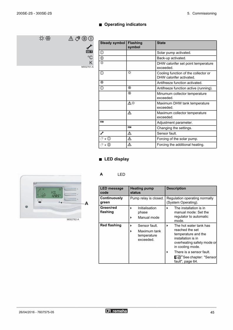
n Operating indicators
Steady symbol Flashingsymbol
State
K Solar pump activated.% Back-up activated.Z DHW calorifer set point temperature
exceeded.K Z Cooling function of the collector or
DHW calorifer activated.E Antifreeze function activated.K E Antifreeze function active (running).
E Minumum collector temperatureexceeded.
aZ Maximum DHW tank temperatureexceeded.
a Maximum collector temperatureexceeded.
T Adjustment parameter. T Changing the settings.] a Sensor fault.R + K a Forcing of the solar pump.
R + % a Forcing the additional heating.
n LED display
A LED
LED messagecode
Heating pumpstatus
Description
Continuouslygreen
Pump relay is closed. Regulation operating normally(System Operating).
Green/redflashing
4 Initialisationphase
4 Manual mode
4 The installation is inmanual mode: Set theregulator to automaticmode.
Red flashing 4 Sensor fault.4 Maximum tank
temperatureexceeded.
4 The hot water tank hasreached the settemperature and theinstallation is inoverheating safety mode orin cooling mode.
4 There is a sensor fault.¼See chapter: "Sensorfault", page 64.
M002761-A
II I
M002762-A
A
200SE-2S - 300SE-2S 5. Commissioning
26/04/2016 - 7607575-05 45

5.2 Check points before commissioning
CAUTION
If the temperature in the solar collectors is higher than130°C, the control system operates in safety mode. Waituntil the evening before start-up or cool down (cover) thesolar collectors.
5.2.1. Domestic hot water calorifer
1. Before start-up, the heating installation must be completelyemptied and rinsed.
2. Make sure that all valves on the circuit are opened.3. Fill the installation with water and check hydraulic tightness.
5.2.2. Primary solar circuit
The system is filled with heat transfer fluid without any airbubbles.
4 Inspect all the connections in the system for leaks.4 Check that the anti-thermosiphon valves on the flow and return
are on position "0°" to allow circulation of the fluid.4 Check that the valve located above the flowmeter is open.4 Check that the filling and draining valves are correctly plugged (the
plugs are delivered in the manuals and instructions bag).4 Check the connection of the solar pump.4 Check that the control system is in automatic mode.¼See the instructions supplied with the control unit and anyremote control unit used.
5.2.3. Primary heating circuit
¼See boiler installation instructions
5.2.4. Electrical connection
Check the electrical connections, particularly the earth.
5. Commissioning 200SE-2S - 300SE-2S
46 26/04/2016 - 7607575-05

5.3 Commissioning procedure
WARNING
4 Initial commissioning must be done by a qualifiedprofessional.
4 During the heating process, water can flow throughthe bleed circuit to guarantee the safety of theinstallation. This phenomenon is perfectly normaland must in no circumstances be hindered.
5.3.1. Secondary circuit (domestic water)
Set the domestic hot water thermostatic mixing valve to the requiredtemperature to avoid scalding when running domestic hot water.
WARNING
The thermostatic mixing valve must be set to maximum at60°C.
5.3.2. Primary solar circuit
1. Inspect all the connections in the system for leaks.2. Leave the fluid circulating round the system for some time and
check again for leaks - (regulator in manual mode).3. Open the vent valve of the manual bleed degasser (bleed again).4. Bring the pressure in the system up to the 2 bar (0.2 MPa) working
pressure by topping up if necessary with heat transfer fluid.5. After several hours of operation, the system should be bled again
(via the manual bleed degasser). After bleeding, check the systempressure and add more fluid if necessary.
6. Check that the control system is in automatic mode.7. Check the anti-thermosiphon valves.8. Check the connection of the solar pump.9. Check the position of the solar hot water tank sensor.10.Complete the "Commissioning protocol" sheet at the end of the
notice.
n Starting and stopping the control system
CAUTION
If the temperature in the solar collectors is higher than130°C, the control system operates in safety mode. Waituntil the evening before start-up or cool down (cover) thesolar collectors.
The installation is switched on.
200SE-2S - 300SE-2S 5. Commissioning
26/04/2016 - 7607575-05 47

The regulator starts an initialisation phase during which the LEDflashes red and green. When initialisation is complete, the regulatorchanges to automatic mode. To initiate the solar pump, a minimumtemperature of 30 °C is required at the collector and a temperaturedifference of 6 °C with respect to the domestic hot water calorifier.Otherwise, the control system is on standby. Switch to manual mode(MAN) to force the solar pump relays and start it up.¼See chapter: "List of the parameters", page 49.
5.4 Reading out measured values
Scroll down the values measured using the ( and ) keys.
Parameter Description RemarksTC Collector temperature S1 sensor.
The value TC shows the temperature in °C given by the collector sensor in real time.TR Calorifier temperature
(Solar exchanger -lower)
S2 sensor.The value TR shows the temperature in °C in real time measured by the sensor in thelower zone of the DHW calorifier.
THR Calorifier temperature(Back-up)
S3 sensor.The value THR shows the temperature in °C in real time measured by the sensor in theupper zone of the DHW tank.
PC % Pump regime Value PC % gives the solar heating pump regime in real time (0-100%).tc Auto-calibration time The value tc shows the self-calibration phase time remaining in seconds.RAP Force back-up On: Back-up powered up.
AUTO: Back-up managed by the control system.¼See user guide.
h P1 Hour run meter on thesolar pump
Reset to zero possible.¼See chapter: "Resetting the values to zero", page 48.
h P2 Hour run meter on theelectrical back-up
Reset to zero possible.¼See chapter: "Resetting the values to zero", page 48.
KWh Amount of heat (kWh) 4 The amount of heat received is calculated according to the parameters input oncommissioning (DMAX).
4 Reset to zero possible.¼See chapter: "Resetting the values to zero", page 48.
Values KWh or MWh give an estimate of the total amount of heat produced by theinstallation in kWh or MWh since commissioning of the control system. The amount ofheat received is calculated according to the parameters input on commissioning (DMAX).
MWh Amount of heat (MWh)
HRE Time ¼See user guide.
5.4.1. Resetting the values to zero
It is possible to reset the value to zero when the symbol T isdisplayed.
1. Select a value using the ( and ) keys.2. Press the B key for 2 seconds. The value is reset to zero.
To suspend the operation, do not press any keys for 5seconds. The control system will automatically go back tothe value display mode.
5. Commissioning 200SE-2S - 300SE-2S
48 26/04/2016 - 7607575-05

5.5 Installer parameters
WARNING
Modifying the factory parameters may impair correctoperation of the solar DHW calorifer. The followingparameters must only be modified by a qualifiedprofessional.
5.5.1. Modifying the installer parameters
1. Go forward to the last display channel (HRE) with the ) key.2. Press the ) key for 5 seconds.
A setting parameter is displayed, with the symbol T.3. Select a parameter using the ( and ) keys.4. Briefly press the B key.
The symbol T flashes, the parameter can be set.5. Modify the parameter using the ( and ) keys.6. Press B to confirm the setting.
5.5.2. List of the parameters
Parameter Description Adjustment range Increment Factorysetting
Remarks
DT Reference temperaturedifference
10/20 K 0.1 20 ¼See chapter: "Description of theinstaller parameters", page 51
tu Self-calibration phase 1 / 5 mn 1 3 ¼See chapter: "Description of theinstaller parameters", page 51
SX Set temperature of thesolar calorifier
4 / 80 °C 1 60 ¼See chapter: "Description of theinstaller parameters", page 51
CMAX Maximum collectortemperature
70 / 120 °C 1 110 ¼See chapter: "Description of theinstaller parameters", page 51
CMIN Minimum collectortemperature
10 / 90 °C 0.5 30 ¼See chapter: "Description of theinstaller parameters", page 51
OAC Collector antifreezeoption
On / OFF OFF 4 On: On4 OFF: Off
¼See chapter: "Description of theinstaller parameters", page 51
TAON Antifreeze functionactivation temperature
-4 / 5.5 °C 0.5 4 Available if OAC = On
TAOF Antifreeze functiondeactivationtemperature
4.5 / 9 °C 0.5 6 Available if OAC = On
FT Tubular collector option On / OFF OFF 4 On: On4 OFF: Off
¼See chapter: "Description of theinstaller parameters", page 51
(1) The parameter is set to On if the S3 domestic hot water sensor is connected
M000393-B
200SE-2S - 300SE-2S 5. Commissioning
26/04/2016 - 7607575-05 49

Parameter Description Adjustment range Increment Factorysetting
Remarks
POMP Pump command mode OnOF / PuLS /PSOL
PSOL 4 OnOF: Heating pump ON or OFF(0% or 100%)
4 PuLS: Pump modulation from 50%to 100%
4 PSOL: PWM solar-controlledheating pump
PN Minimum solar pumprate
20 / 100% 1 30
OTHR Activation of theelectrical back-up
On / OFF OFF(1) 4 On: Electrical back-up present4 OFF: No electrical back-upIf the S3 domestic hot water sensor isconnected, the OFF setting is notavailable.
THRn Nighttime back-up setpoint temperature
40 / 95 °C 0.5 55 ¼See chapter: "Description of theinstaller parameters", page 51
tn O Back-up activation timeat night
00:00 / 23:45 00:15 23:00
tn F Back-up deactivationtime at night
00:00 / 23:45 00:15 07:00
O td Daytime back-up option On / OFF ON 4 On: On4 OFF: Off
¼See chapter: "Description of theinstaller parameters", page 51
THRd Daytime back-up setpoint temperature
40 / 95 °C 0.5 55 ¼See chapter: "Description of theinstaller parameters", page 51
td O Daytime back-upactivation time
00:00 / 23:45 00:15 16:00 Available if O td = On
td F Daytime thermostatdeactivation time
00:00 / 23:45 00:15 18:00 Available if O td = On
DMAX Maximum flow rate (l/min)
0.5 / 100 10 - 1 - 0.1 3 ¼See chapter: "Description of theinstaller parameters", page 51
GELT Antifreeze type 0 / 1 / 2 / 3 / 4 1 3 4 0: Water4 1: Propylene glycol4 2: Ethyl glycol4 3: Tyfocor LS / G-LS4 4: Greenway
GEL% Antifreeze concentration 20 / 70 % 1 45 If GELT = 1 or 2MAN Manual mode Auto / 1 On / 1 OF AUTO 4 Auto: Automatic mode
4 1 On: Solar pump activated4 1 OF: Solar pump deactivated
XXX Software version (1) The parameter is set to On if the S3 domestic hot water sensor is connected
5. Commissioning 200SE-2S - 300SE-2S
50 26/04/2016 - 7607575-05

5.5.3. Description of the installer parameters
n Reference temperature difference - DT
The regulator reads the temperatures measured by sensors TC andTR and compares the resulting temperature difference with theswitching-on difference which is preset to 6 K. The regulator tries toachieve a temperature difference of 20 K (factory setting) betweenthe collector and the tank to produce high temperature hot water asrapidly as possible.
n Self-calibration phase - tu
When the solar collector reaches the minimum temperature CMINand the predefined temperature difference of 6 K with the DHW tanktemperature, the control system triggers the solar circulating pump atfull regime for the period defined by the parameter tu. During thisphase, any air bubbles in the solar collectors or pipes are evacuatedto the solar station thanks to the high circulation speed in the pipesand eliminated by the air vent.
n Set temperature of the solar calorifier - SX
The set temperature SX is the desired temperature for the solarcalorifier. The higher the set temperature for the calorifier, the greaterthe energy stored. Setting to 60°C is suitable for normal use with dailydraw-offs.
CAUTION
During extended absences, we recommend lowering theset point temperature in the solar DHW calorifier to 45°C.When the user is present, the set point must be set to60°C.
n Maximum collector temperature - CMAX
The maximum collector temperature CMAX helps to protect thecollector against overheating.When the DHW tank set point temperature (SX) is reached, the solarpump stops. As soon as the solar collector reaches the maximumtemperature CMAX, the solar pump runs until the temperature in thesolar collector is again 5 K lower than the maximum collectortemperature CMAX. The DHW tank temperature can increase until itreaches its maximum temperature of 80°C. If the DHW tanktemperature exceeds 80°C, the system effects an emergencyshutdown.
M000393-B
M000397-B
I
M002799-A
M002764-A
I
200SE-2S - 300SE-2S 5. Commissioning
26/04/2016 - 7607575-05 51

n Minimum collector temperature - CMIN
The minimum collector temperature function CMIN prevents the solarpump from starting up too frequently in the event of low temperaturesin the solar collector. The minimum collector temperature CMIN mustbe exceeded in order for the solar heating pump to be able to startup.
n Collector antifreeze option - OAC
CAUTION
The antifreeze function should only be used if non-glycolwater is used as the heat transporting fluid.
The function takes heat from the DHW calorifer; wetherefore recommend using it only in regions where thetemperature rarely falls below 0°C.
When the collector temperature is lower than the TAON temperature,the antifreeze function activates the solar pump in order to make theheat-transporting fluid circulate between the collector and the DHWcalorifer to prevent it freezing. When the collector temperatureexceeds the TAOF temperature, the antifreeze function stops thesolar pump.
CAUTION
The collector antifreeze function only runs if the DHW tanktemperature is higher than the collector temperature. Thecollector antifreeze function is deactivated if the DHW tanktemperature is lower than 5°C.
n Tubular collector option - FT
The tubular collector function is used to take into account the positionof the temperature sensor in the tubular collectors. If the regulatordetects a temperature rise in the collector of 2 K compared to the lastmeasurement, the solar pump runs at full speed for 30 seconds tomeasure the current average temperature. The measuredtemperature thus becomes the new reference temperature. If themeasured temperature (new reference) then increases again by 2K, the solar pump starts again for 30 seconds. The regulator switchesautomatically to solar heating mode if the temperature differencebetween the collector and the calorifer exceeds the switching-ontemperature difference when the solar pump is operating or thesystem is stopped. If the collector temperature falls by 2 K while thesystem is stopped, the tubular solar collector activation temperatureis rechecked.
M002765-A
I
M002766-A
I
I
M002800-A
I
M002801-A
I
M000399-C
5. Commissioning 200SE-2S - 300SE-2S
52 26/04/2016 - 7607575-05

n Pump command mode - POMP
The POMP parameter is used to select the correct command programfor the solar pump, according to the type of pump used. PSOL control(default setting) is designed for PWM solar-controlled heating pumps,PuLS control for conventional frequency-modulation heating pumpsand OnOF control for "ON/OFF heating pumps. ¼See chapter:"List of the parameters", page 49.
n Minimum solar pump rate - PN
. The PN parameter is used to define a minimum value for the solarpump rate at the R1 relay outlet. The lower the pump rate, the lowerits flow rate. ¼See chapter: "List of the parameters", page 49.
n OTHR electrical back-up option
If the S3 domestic hot water sensor on the electrical back-up isconnected, the OTHR parameter is automatically set to On. As aresult, it is impossible to modify the setting to OFF.If the S3 domestic hot water sensor is not connected, there is noelectrical back-up. The OTHR parameter must be set manually toOFF.
n Nighttime back-up set point temperature - THRn(The parameter is only displayed if OTHR is set to On)
A Hourly nighttime range
The THRn temperature is the set point to be reached by the DHWtank using its back-up at night. The nighttime period is programmedbetween the start and end times tn O and tn F respectively.
n Daytime back-up option - O td(The parameter is only displayed if OTHR is set to On)
The O td option, when the parameter is set to On, enables use of theback-up during the day. The O td option, when the parameter is setto Off, prohibits use of the back-up during the day. The RAPparameter (forced back-up operation) always takes precedence overthe O td parameter and the switch setting.
Installer parameter O td OnUser setting RAP Auto
3-position switch E 0 Z
Back-up at night Activated between tn O and tn F until THRn Off Activated between tn O and tn Funtil THRn
Back-up during the day Activated between td O and td F until THRd Off Off
I
M002802-A
I
A001032-A
M002767-B
tn O
0h 12h 0h
tn F
1
200SE-2S - 300SE-2S 5. Commissioning
26/04/2016 - 7607575-05 53

Installer parameter O td OFFUser setting RAP Auto
3-position switch E 0 Z
Back-up at night Activated between tn O and tn F untilTHRn
Off Activated between tn O and tn F untilTHRn
Back-up during the day Off Off Off
Installer parameter O td On or OFFUser setting RAP On
3-position switch E, 0 or ZBack-up at night Activated until the set point THRn is reachedBack-up during the day
n Daytime back-up set point temperature - THRd(The parameter is only displayed if OTHR is set to On)
A Hourly nighttime range
Z Hourly daytime range
THRd is the set point temperature to be reached by the DHW tankusing its back-time during the day. The nighttime period isprogrammed between the start and end times td O and td Frespecively. With a back-up, the programmed period is set in thefactory to between 16:00 h and 18:00 h, i.e. at the end of the day whenthe solar contribution is less and just before the draw-off period.
n Maximum flow rate - DMAX
In order for the regulator to calculate the quantity of heat produced bythe installation (parameter KWh / MWh), input parameter DMAX. Theparameter DMAX is equal to the flow in litres per minute in the solarcircuit. Establish the DMAX value using the table below, according tothe number of collectors. When the flow is input incorrectly, thedisplay KWh / MWh will also be incorrect.
Number of flat collectors Flow rate (l/min)1 6.52 53 4.54 45 3.52x2 102x3 13
If the installation is fitted with a flowmeter, take a readingof the flow rate value (when the heating pump is running atfull regime) to input the DMAX parameter.
M002768-A
td O td F tn O
0h 12h 0h
tn F
1 2
L000456-B
A
5. Commissioning 200SE-2S - 300SE-2S
54 26/04/2016 - 7607575-05

n Antifreeze type - GELT
The GELT parameter is used to set the type of antifreeze used. Theantifreeze concentration value is preset for using Tyfocor LS / G-LSand Greenway products. If using another antifreeze, select the settingvalues 1 or 2 and then set the GEL% parameter. ¼See chapter:"List of the parameters", page 49.
I
M002804-A
200SE-2S - 300SE-2S 5. Commissioning
26/04/2016 - 7607575-05 55

6 Checking and maintenance
6.1 General instructions
CAUTION
4 Maintenance operations must be done by a qualifiedengineer.
4 Only original spare parts must be used.
6.2 Safety valve or safety unit
The safety valve or unit on the domestic cold water inlet must beoperated at least once a month to ensure proper operating and toprevent from any overpressure which may that may damage thedomestic hot water calorifier.
WARNING
Failure to abide by this maintenance rule may damage thedomestic hot water calorifier and void its warranty.
6.3 Cleaning the casing material
Clean the outside of appliances using a damp cloth and a milddetergent.
6.4 Checking the magnesium anode
Check the condition of the anodes at the end of the first year. It isnecessary to determine the periodicity of subsequent checks as ofthe first check, according to wear and tear on anodes. Magnesiumanodes must be checked at least every 2 years.
1. Remove the inspection hatches.¼See chapter: "Removing the inspection hatches", page57.
2. Descale the calorifier if necessary.3. Measure the diameter of the anode.
Replace the anode if its diameter is less than 15 mm.4. Reassemble the anode/inspection hatch unit.¼See chapter: "Remounting the inspection hatches", page58.
Ø > 15 mm =
Ø < 15 mm =
C003699-B
6. Checking and maintenance 200SE-2S - 300SE-2S
56 26/04/2016 - 7607575-05

6.5 Descaling
In regions with hard water, annual descaling of the appliance isrecommended in order to maintain its performance.
1. Remove the inspection hatches.¼See chapter: "Removing the inspection hatches", page57.
2. Check the magnesium anode each time the hatch is opened.¼See chapter: "Checking the magnesium anode", page 56.
3. Remove limescale deposits in the form of sludge or strips in thebottom of the tank. On the other hand, do not touch limescaleadhering to the walls of the tank as it provides effective protectionagainst corrosion and improves the insulation of the DHWcalorifier.
4. Remove limescale deposits from the exchanger to guarantee itsperformance.
5. Fit the unit together.¼See chapter: "Remounting the inspection hatches", page58.
6.6 Removing and remounting the inspection hatches
CAUTION
To guarantee tightness, the gasket unit must be replacedeach time the hatch is opened.4 Use a new lip gasket and retainer ring for the top
inspection hatch.4 Have a new gasket on hand for the side inspection
hatch.
6.6.1. Removing the inspection hatches
1. Turn off the domestic cold water inlet.2. Drain the calorifier.
The domestic cold water inlet is also the drain opening.
3. Remove the inspection hatches.
200SE-2S - 300SE-2S 6. Checking and maintenance
26/04/2016 - 7607575-05 57

6.6.2. Remounting the inspection hatches
1. Replace the lip seal and position it in the visit opening, making surethat you place its lug outside the DHW tank.
2. Replace the sheet gasket.3. Fit the unit together.
CAUTION
Use a torque wrench.
Torque applied to the anode: 8 N·m.The flange mounting bolts must not be excessively tight.
Flange Torque loadLip gasket 6 N·m +1/-0Sheet gasket 15 N·m
Approximately 6 N·m is obtained by manipulating the boxspanner with the small lever and 15 N·m by manipulatingit with the large lever.
4. After reassembly, check the watertightness of the lateral flange.5. Switch on.¼See chapter: "Commissioning procedure", page 47.
L000389-C
1
6x
2
L000594-A
6. Checking and maintenance 200SE-2S - 300SE-2S
58 26/04/2016 - 7607575-05

6.7 Inspection and maintenance of the solar circuit
6.7.1. Maintenance operations to be performed
WARNING
Use only the same fluid as for refilling. Do not mix differentfluids.
1. Check the level of the heat transporting fluid. Top up the solar fluidif necessary.
2. Check the antifreeze protection.3. Check the pressures of the installation and the expansion vessel.4. As the heat transporting fluid leaks much more readily than water,
carry out a visual check on the tightness of all fittings and gaskets.5. Check operation of the installation.
6.7.2. Adding heat transporting fluid
CAUTION
Addition of heat transporting fluid after the safety valve has beenswitched on
When the safety valve is switched on, a certain quantity of heattransporting fluid overflows into the glycol collection vat. Top up thesolar circuit again by pumping the fluid from the glycol collection vat.¼See chapter: "Filling the primary solar circuit", page 38.
4 The filling pressure must be more than 0.5 bar (0.05 MPa) abovethe expansion vessel pre-load pressure.
CAUTION
4 Check the installation of the collector sensor.4 Do not use a manual filling pump.
CAUTION
As the heat transporting fluid leaks much more easily thanwater, carry out a visual check on the tightness of allfittings and gaskets after a few hours’ operation at normaloperating pressure.
200SE-2S - 300SE-2S 6. Checking and maintenance
26/04/2016 - 7607575-05 59

6.8 Maintenance form
Maintenance N°: .........................................
Description of the installation
Checks
Owner ..........................................................................................................Street ...........................................................................................................Town/Postcode.............................................................................................Tel. ................................................ Fax........................................................Mobile ..........................................................................................................E-mail ...........................................................................................................
Company name ..........................................................................................Street ...........................................................................................................Town/Postcode ............................................................................................Tel. ................................................. Fax.......................................................Mobile ..........................................................................................................E-mail ..........................................................................................................Installer ........................................................................................................
Solar installation for: Hot water preparation Additional heating Swimming pool heating
Solar collectors: ................................................... Area .................................m2
DHW tank: ..................................................... Solar station: . ..............................................................
System pressure checked .......................... bar pH value ......................
Pre-load in the solar tank .......................... bar
Antifreeze protection checked .......................... ° C
Sealing: Inspection:
Collector OK OK
Pipes OK OK
Solar station OK OK
DHW tank OK OK
Regulation Checking the operation OK
Collector temperature TC: ..................... ° C
DHW sensor temperature TS: ..................... ° C
Temperature Te: ..................... ° C
Amount of heat AH: ..................... kW
Enamelled tanks: Sacrificial anode checked condition satisfactory must be replaced
Domestic hot water thermostatic mixing valve Set to...............°C
Check the general condition of the equipment and its components
General scaling condition: condition satisfactory Descaling required
Checking the operation OK must be replaced
Check the wiring harness OK must be replaced
Check the safety thermostat and its wiring OK must be replaced
Check the heating resistor OK must be replaced
Heat insulation OK must be replaced
6. Checking and maintenance 200SE-2S - 300SE-2S
60 26/04/2016 - 7607575-05

Installation controlled in integralityInstallation in perfect conditionInstallation faults
....................................................................................................................................................................................................................................
....................................................................................................................................................................................................................................
....................................................................................................................................................................................................................................
....................................................................................................................................................................................................................................
....................................................................................................................................................................................................................................
....................................................................................................................................................................................................................................
....................................................................................................................................................................................................................................
....................................................................................................................................................................................................................................
....................................................................................................................................................................................................................................
....................................................................................................................................................................................................................................
....................................................................................................................................................................................................................................
....................................................................................................................................................................................................................................
....................................................................................................................................................................................................................................
....................................................................................................................................................................................................................................
....................................................................................................................................................................................................................................
....................................................................................................................................................................................................................................
....................................................................................................................................................................................................................................
....................................................................................................................................................................................................................................
....................................................................................................................................................................................................................................
....................................................................................................................................................................................................................................
....................................................................................................................................................................................................................................
....................................................................................................................................................................................................................................
Place: ............................................................................................................. Date:.................................................................................................
Owner's signature Installer's signature
200SE-2S - 300SE-2S 6. Checking and maintenance
26/04/2016 - 7607575-05 61

6.9 Installation report
Description of the installation
Solar outlet and return checks
Regulator function check
Place of installation ........................................................................Owner ............................................................................................Street .............................................................................................Town/Postcode...............................................................................Tel. ................................................ Fax..........................................Mobile ............................................................................................E-mail .............................................................................................
Company name ............................................................................Street .............................................................................................Town/Postcode ..............................................................................Tel. ................................................. Fax.........................................Mobile............................................................................................E-mail ............................................................................................Installer ..........................................................................................
Solar installation for: Hot water preparation Additional heating Swimming pool heating
Solar power sensor: Type: ............................................................................................... Quantity: ..................
Type of installation: On roof Roof-integral Installation On flat roof
Pipes: Duo-Tube Cu 15 Cu 18
Other pipes ø .........................................mm Length ........................m
Insulation: ...................mm Type/brand ................................................................
Tank: Type: ...............................................................................................
Solar station: Solar station integrated in the tank Other: ...................................
Solar fluid: LS l (volume): ................
System pressure: ................................bar Pre-load in the solar tank: ................................bar
For vertical collectors side-by-side or horizontal collectors one on top of the other:- Connect the return (cold)- Connect the outlet (hot) to the coil- Mount the sensor on the side where the hot coil leaves the collector (outlet)
For horizontal solar panels:- checks in accordance with the assembly diagram
Return OK
Outlet OK
Sensor position OK
10-minute bleed cycle OK MCDB unloading pump, swimming pool pump R8Continuation in matched flow mode OK DHW pump - MCDB R9Collector temperature (TC) S1 = ....... °C Amount of heat AH = ........ KWExchanger flow temperature (TE) S2 = ....... °C Reference temperature difference DT = ........ KDomestic hot water tank temperature 1 lower zone (TS) S3 = ....... °C Zone changeover temperature SZ = ........ °CDomestic hot water tank temperature 1 upper zone (TM) S4 = ....... °C Set temperature SX = ........ °CDomestic hot water tank temperature 1 central zone / Pool temperature / MCDB
S5 = ....... °C Maximum collector temperature CX = ........ °C
Biomass boiler temperature S8 = ....... °C Self-calibration phase tu = ........ min.Input temperature heat meter S10 = ....... °C Adjustment parameter PN = ........ %Output temperature heat meter S11 = ....... °C Maximum flow rate FX = ........ l/minprimary circuit pump, speed control R1 DHW booster temperature settings:secondary circuit pump, speed control R2 - boiler circuit ..........................°CReversal valve domestic hot water tank zones R3 - Electric heating resistance ..........................°CBiomass boiler pump R4MCDB reversal valve R5
6. Checking and maintenance 200SE-2S - 300SE-2S
62 26/04/2016 - 7607575-05

Inspection of the installation
Readjustments....................................................................................................................................................................................................................................
....................................................................................................................................................................................................................................
....................................................................................................................................................................................................................................
....................................................................................................................................................................................................................................
....................................................................................................................................................................................................................................
....................................................................................................................................................................................................................................
....................................................................................................................................................................................................................................
....................... ............................................................................................................................................................................................................
Remarks....................................................................................................................................................................................................................................
....................................................................................................................................................................................................................................
....................................................................................................................................................................................................................................
....................................................................................................................................................................................................................................
....................................................................................................................................................................................................................................
....................................................................................................................................................................................................................................
....................................................................................................................................................................................................................................
Place: ............................................................................................................. Date:.................................................................................................
Owner's signature Installer's signature
Components on roof:All mounting bolts tight yesAll connections checked and leak-free yes
Solar station:Outlet and return connections correct yesOutlet and return thermometers present and checked yes
Tank:Cold water safety kit installed yesPressure reducer set at ................. bar yesThermostatic mixing valve with anti-thermosiphon circuit connected to the solar tank yesThermostatic mixing valve set to..............°C yesTank insulation checked yesAll connections installed yes
Expansion vessel:Pressure of preload of the controlled expansion vessel yes
Assembly instructions (solar collector, tank, complete station, regulator) handed to the owner yesSolar installation operation (regulator) explained to the owner yes
200SE-2S - 300SE-2S 6. Checking and maintenance
26/04/2016 - 7607575-05 63

7 Troubleshooting
7.1 Electricity supply
DANGER
Before any work, switch off the mains supply to the controlsystem.
If the LED or the display are off, check the mains supply to the controlsystem. The regulator is protected by a 4 A fuse.
1. Remove the control system cover by unscrewing the 2 screws.2. Check the fuse and change it if necessary. A spare fuse can be
found in the control system housing.3. Put the cover back in place and secure with the screws.
CAUTION
If the control system still does not work, replace it.
7.2 Sensor fault
Steady symbol Flashing symbol State] a The sensor is defect.
1. Check the temperature display channels for each sensor.
TC Solar collector temperature sensorTR DHW tank temperature sensorTHR Back-up temperature sensor
2. If the channel does not display the temperature, the sensor isdefect. An error code is displayed in place of the temperature. Thedefective sensor flashes very rapidly on the display.
Error code Description Checking / solution888.8 Cable breakage Check the cable for the sensor concerned-88.8 Short circuit Check the cable for the sensor concerned
3. If the sensor is still defect, check its value with an ohmmeter.
¼See chapter: "Technical specifications", page 16.
M002769-B
1 2
3
M002770-B
7. Troubleshooting 200SE-2S - 300SE-2S
64 26/04/2016 - 7607575-05

7.3 Incidents and solutions
Description Checks SolutionsThe indicator light is off. The fuse is defect. Replace the fuse.
¼See chapter: "Electricity supply",page 64.
The current has been cut. Restore the current.The solar pump is running but the DHW calorifiertemperature is not increasing.
Air bubbles are present in thecircuit.
Vent the heating installation.Check the pressure.Activate and deactivate the pumpseveral times in a row.
The solar collector filter is clogged. Clean the filter.The solar pump starts and stops continually. The solar collector sensor is in the
wrong place.Place the collector sensor on the solarflow, the hottest point on the collectoroutlet.
The temperature difference set onthe control system is too small.
Modify the DT value.
The tubular collector option isunsuitable.
Modify the FT value.
The solar pump starts later than expected. The DT value is too high. Modify the DT value.The collector sensor is incorrectlyset or placed.
Modify the DT value.Place the collector sensor on the solarflow, the hottest point on the collectoroutlet.
The temperature difference between the DHWcalorifier and the solar collector increases when thesystem is activated.The solar circuit cannot evacuate the heat.
The solar pump is defect. Change the solar pump.The circuit is blocked. Clean the solar circuit.The circuit is scaled up. Descale the circuit.
The solar pump is not running but the collectortemperature is higher than the DHW calorifiertemperature.
The current has been cut. Check the fuse in the control system.Check the electricity supply.
The pump does not start in manualmode.
The pump is blocked.Check that the PWM cable isconnected to the pump.Change the solar pump.
The pump is not receiving powerfrom the control system.
Check the fuse in the control system.Check the electricity supply.Change the control system.
The DT value is too high. Modify the DT value.The tank temperature drops even though there isno draw-off.
The pump operates during thenight.
Check the programming of the controlsystem.
There is recirculation in the solarcircuit or the domestic hot watercircuit.
Place a non-return device in the solaror domestic hot water circuit.
The collector temperature is higher than the outsidetemperature at night.
The non-return valves are notworking.
Check the non-return valves.
Thermosiphon circulation is toopowerful.
Use more suitable non-return valves.
200SE-2S - 300SE-2S 7. Troubleshooting
26/04/2016 - 7607575-05 65

8 Spare parts
8.1 General
When it is observed subsequent to inspection or maintenance workthat a component in the appliance needs to be replaced, use onlyoriginal spare parts or recommended spare parts and equipment.
Always ensure that your return package is accompaniedby the completed return form, see attached example.
CustomerReference DateName Address Town/Postcode Telephone Contact person Order number
Code no. Description Serial number(1) Type Installation date Reason for the exchange Reference
(1) This information can be found on the rating plate.
8. Spare parts 200SE-2S - 300SE-2S
66 26/04/2016 - 7607575-05

8.2 Spare parts
8.2.1. Domestic hot water tanks
C004575-B
1
10
3
19
7
15
11
14
10
11
12
13
10
11
12
16
9
8
54
12
11
10
12
18
17
20
2
6
200SE-2S - 300SE-2S 8. Spare parts
26/04/2016 - 7607575-05 67

Markers Reference Description 200SE-2S 300SE-2S1 97860646 Adjustable foot M10 x 35 x x2 200022499 Plug 3/4" x x3 300026994 Insulation, buffer tank x x4 300026735 Side cover x x5 300026876 Side insulation x x6 200021489 Domestic hot water thermostatic mixing valve x x7 200021501 Inspection trap screws x x8 300026031 EPDM seal x x9 89705511 7 mm gasket + 5 mm retainer ring x x
10 95014035 Seal ø 35 x 8.5 x 2 x x11 94974527 Nylon brace x x12 89604901 Anode earthing wire x x13 89708901 Complete anode diameter 33 mm - length 330 mm (1x) - For top trap x 13 89525511 Complete anode diameter 33 mm - length 290 mm (1x) - For top trap x x13 89608950 Complete anode diameter 33 mm - length 420 mm (1x) - For top trap x14 89608950 Complete anode diameter 33 mm - length 420 mm (1x) - For side trap x x15 7608649 Complete side trap with anode, gaskets and screws x x16 200022433 Complete top inspection trap with anode and gasket x 16 200022466 Complete top inspection trap with anode and gasket x17 300010846 Solar sensor probe FKP6 lg 2.5 m x x18 95365613 Contact spring for pocket x x19 300027443 Cover for RAL9006 tank Diameter 605.5 x x20 97930801 Solar calorifier sensor FRP6 lg 2.5 m x x
8. Spare parts 200SE-2S - 300SE-2S
68 26/04/2016 - 7607575-05

8.2.2. Solar station
n Overview
C004576-B
1
2
3
4
15
78
9
10
12 14
13
11
5
17
18
6
16
Markers Reference Description1 300027858 Medium cover2 7626021 Sol AEL regulator3 300027856 Control system support AEL4 300027874 Insulated copper pipe - Top5 300027873 Insulated copper pipe - Left6 300027872 Insulated copper pipe - Right7 300028300 Copper pipe - Expansion vessel connection8 300027870 18-litre expansion vessel9 300027869 Expansion vessel bracket
10 300027871 3/4" connection for expansion vessel11 300019281 Glycol recovery drum - 2.5 litres
12 300018820 Ribbed flexible hose - Diameter 22 mm - Fittings3/4" - Length 1700 mm
13 95013062 Green seal 30x21x2
200SE-2S - 300SE-2S 8. Spare parts
26/04/2016 - 7607575-05 69

Markers Reference Description14 95013060 Green seal 24x17x215 97310700 Grease for O-ring16 300027855 Control system support Ai17 300027862 Red metal thermometer18 300027938 Blue metal thermometer
n Detailed drawing
1
6
13 14
6
7
88
9
18
19
10
11
11
23
24
26
15
16
17
20
21
17
25
22
12
12
3
4
2
5
L000576-C
22
Markers Reference Description1 300028533 Back insulation module2 300002992 Washer Ø 25x8.4x1.53 300028534 Screw M8x20
8. Spare parts 200SE-2S - 300SE-2S
70 26/04/2016 - 7607575-05

Markers Reference Description4 300028535 Wall console5 300028536 Screw M8x256 300028538 Cone union body retaining bush7 300026341 Valve 3/4" FF Fixed valve pin8 300019551 Locating pin9 300004141 Bleeder valve stopper 3/8"
10 300028537 Degasser 3/4"11 300028539 cone union body Ø 18.2x9 mm12 300028540 Cone union body nut Ø 18 mm13 300026332 Return tap14 300022601 Seal ø 24x17x2 mm15 97930837 Safety valve 6 bar (0.6 MPa)16 300026337 Connection body17 300026343 Drain cock 1/2"18 300028531 3/8" male/female elbow19 300003218 Pressure gauge connection part20 300028532 0-6 bar pressure gauge diameter 50 mm21 300010046 1" nut22 300010041 Seal ø 1/2"23 7626990 Circulator 24 300010944 Circulating pump cable - 2 m25 300028541 1/2" flow rate regulator - 0.5-15 litres/minute26 7643715 Circulating pump cable PWM
8.2.3. Electric heating resistance For 200/400)only
Markers Reference Description1 100019163 Electric heating resistance 1.5 kW/230 V~1 100019164 Electric heating resistance 2.3 kW/230 V~2 300027886 Gasket 60x48x3
L000572-D
1
2
200SE-2S - 300SE-2S 8. Spare parts
26/04/2016 - 7607575-05 71
en
Appendix
Information on the ecodesign and energy labelling directives
Contents1 Specific information . . . . . . . . . . . . . . . . . . . . . . . . . . . . . . . . . . . . . . . . . . . . . . . . . . . . . . . . . . . . . . . . . . . . . . . . . . . . . . . . . .3
1.1 Recommendations . . . . . . . . . . . . . . . . . . . . . . . . . . . . . . . . . . . . . . . . . . . . . . . . . . . . . . . . . . . . . . . . . . . . . . . . . . . . . 31.2 Ecodesign Directive . . . . . . . . . . . . . . . . . . . . . . . . . . . . . . . . . . . . . . . . . . . . . . . . . . . . . . . . . . . . . . . . . . . . . . . . . . . . 31.3 Technical data - Hot water storage tank . . . . . . . . . . . . . . . . . . . . . . . . . . . . . . . . . . . . . . . . . . . . . . . . . . . . . . . . . . . . . 31.4 Circulation pump . . . . . . . . . . . . . . . . . . . . . . . . . . . . . . . . . . . . . . . . . . . . . . . . . . . . . . . . . . . . . . . . . . . . . . . . . . . . . . . 31.5 Disposal and Recycling . . . . . . . . . . . . . . . . . . . . . . . . . . . . . . . . . . . . . . . . . . . . . . . . . . . . . . . . . . . . . . . . . . . . . . . . . .3
Contents
2 7607575 - ErP02 - 21042016

1 Specific information
1.1 Recommendations
NoteOnly qualified persons are authorised to assemble, install and maintain the installation.
1.2 Ecodesign Directive
This product conforms to the requirements of European Directive 2009/125/EC on the ecodesign of energy-related products.
1.3 Technical data - Hot water storage tank
Tab.1 Technical parameters for hot water storage tank 200SE-2S 300SE-2S
Storage volume V l 225 300Standing loss S W 75 92
1.4 Circulation pump
NoteThe benchmark for the most efficient circulators is EEI ≤ 0.20.
1.5 Disposal and Recycling
NoteRemoval and disposal of the domestic hot water tank must be carried out by a qualified installer in accordance with local and national regulations.
1. Cut the electricity to the domestic hot water tank.2. Disconnect the cables on the electrical components.3. Close the domestic water inlet valve.4. Drain the installation.5. Dismantle all water connections fitted to the domestic hot water tank
outlet.6. Scrap and recycle the domestic hot water tank in accordance with
local and national regulations.
1 Specific information
7607575 - ErP02 - 21042016 3

1 Specific information
4 7607575 - ErP02 - 21042016


© CopyrightAll technical and technological information contained in these technical instructions,as well as any drawings and technical descriptions supplied, remain our propertyand shall not be multiplied without our prior consent in writing.
26/04/2016
7607575-001-05