l seotion pil'mrs used as in video …downloads.bbc.co.uk/rd/pubs/reports/1949-31.pdf ·...
TRANSCRIPT
'RESEAROH DEP.iffi'l'lvISNT k ... _.... ....... __ • ..-__
UNSYM[\
UNSYJI!tMETRIOAL ~ SEOTION ]lILTERS Uf'iliD J5J mTERV)LVE OOUPLINGS --.... -----,-----,,---- .. --........... ,----..-..::------~.-.----------... .. _. - - ,-.--
Section ..... --~ .......
1
2
3
m VIDEO PRE::UENCY .AI.iPLTI'lIERS ... c_ ... __ <-_~ ... _-.. ___ ~.~----......-,-----..
SUM};IARY - - - -
JNTRODUOT ION
:rESIGN TBEORY -
PHASE COlli'1EOT ION --
1
1
2
9
3.1 Practical Considerations 9 3.2 Design of Phase-Equalising Sections 11
OONOLUSIONS
m;PERENCES
-.. - - 13
14

Research Department
Report written by G.G.,Gouriet
P~POBT NO. T.024
§~,i~l No. 1949L31
PRIVATE .A:ND OONFIDENTIAL
September 1949.
Fig. Nos. 1 to 14.
UNSYM]''BTAr..9~ 7l: SEOTION FILTERS USED AS I~l"TERV.ALVE OOUPLINGS
TI{ VIDEO F:RE(llIENCY f-i.!''PLIFIEBS ---' -' -
.SUMMAR~
It is shown that by a suitable choice of the parameters which define the desi@l of unsymmetrical 7l: section filters, simple expressions for the perfonnance are obtained from which t:le steady-state or the transient response may be calculated. Curves of the amplitude characteristic and the group-delay characteristic are given for various values of the variable parameters and cases of particular interest are discussed. Finally, the requirement of phase ~ equalisation is discussed briefly, and data for the. design of phase equalising networks are given.
The use of 7l: section filters as a means of providing efficient intervalve couplings in video-frequency amplifiers has received much attention in recent years. Various authors (1) have shown that the voltage gain-bandwidth product of a stage employing a simple 1~ section coupling, in which the stray capacities of tne circuit form the shunt elements, is of' the order of 1.5 times as great as is obtained using the two-terminal shunt-peaking netvvork. Nore complicated couplings employing a combination of the shunt-peaking circuit and the 7l:
section filter, and providing in addition a greater degree of phase linearity, have also been described (2), but the disadvantage of such circuits is the critical nat,rre of the adjustments necessary to obtain the optimum performance. A better solution, paJ.~ticularly applicable to the case of. multi-stage video amplifiers, is to adopt the simple filter couplings throughout and correct the overall phase characteristic by means of a suitable phase equalising network.
The transient response of the various forms of such couplings has also received considerable attention, but in practice the response ofa single section is seldom of interest, whilst to deduce the overall transient response of a number of cascade sections from that of a single section is, in general, a formidable task. Kal lmann , Spe:lcer and Singer (3) have deal t comprehensively with the transient response of a large number of alternative types of filter and have included the Case of Cascade stages by means of an artifice,

\
- 2 -
bnt the filters treated are without phase correction, and the resul ts are of limited application, since wi th the efficient t (pes of coupling the degree of overshoot is prohibitive when many stages are used.
The purpose of this report is to present desi:::;n data and generalised performance curves for various values of, termination and varying degrees of asymmetry, so that filters may not only be readily dosigned to provide a constant runplitude characteristic but Il1..ay also 'be chosen to f\11fil the purposes' of equalising networks. Curves of the group delay characteristic are given in each case and data for the design of phase equalising sections are included.
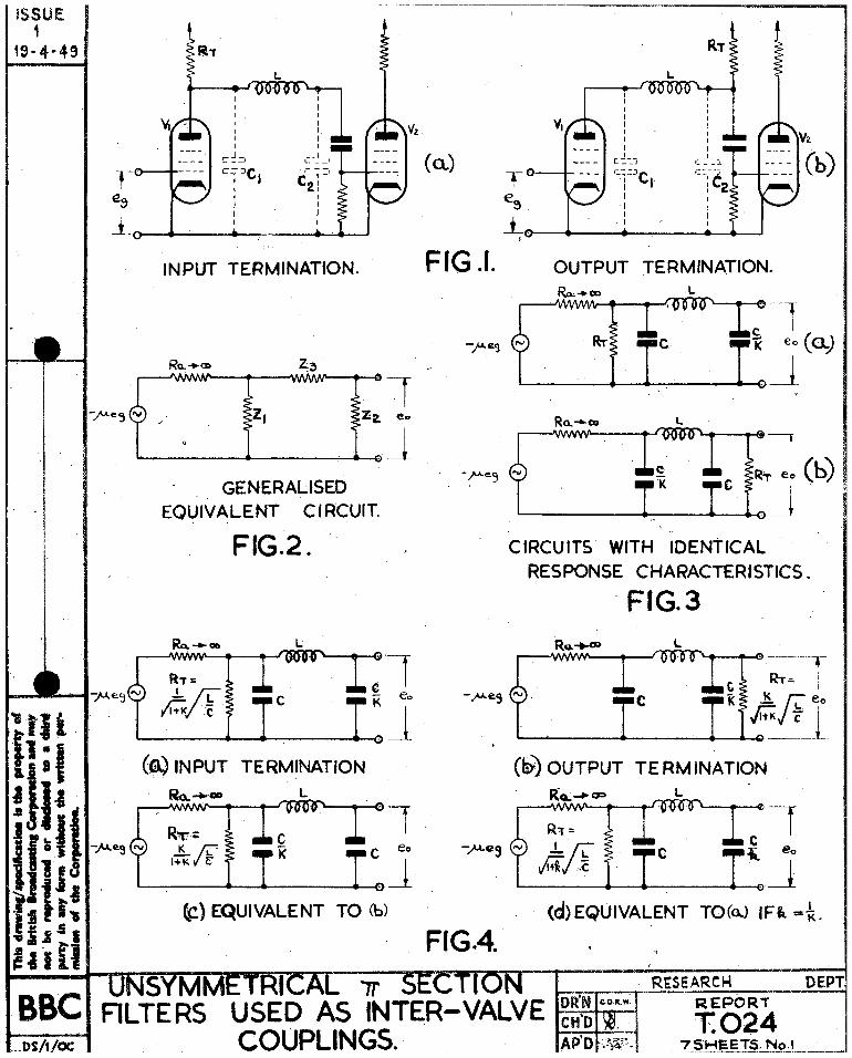
In this section we shall deal with the design of intervalve I couplings of the simple type as shown in ~igs. 1 (a) and (b), and these tvvo cases we shall designate llinput terminatedl1 and ,11 output terminated;! respectively. In general, the valve will be f'. pentode, ho.vine; a magnification factor and mutual conductance of I-L and gm respecti vely, nnd since we ore deD.ling with vdde band video OI£lplifiers, the value of P"l', the tenninating resistnnce, will in all cases be very small compared yvjth the valve impedence, Ra, and we shall, therefore, justifiably regard the latter as infinite.
The generalised equivalent circuit is ahovm in Fig. 2, ° g being the voltage applied to the grid of the valve.
li'or the output voltage, 00' we have,
e = - f.L Or-Zl Z2
o G R~-rii -;-Z2 +-Z3) + Zl-rz;+z3")
Putting /l = Sm Ra where E?m = mutual conductance, and letting Ra ~ 00 we obtain
••••••• 0 •• (2)
Since we are only interested in the characteristic of the . transfer impedance, ZT, we may write more simply:-
Zl Z2 Zl +Z2+Z.3
••••••••••••••••••• (.3)

- 3
A point of fundamental importance to be noted from (3) is that the charac.teristic of the network is unaltered by the interchange of 21 and Z2. Thus the networks of' l~igs. 3 (a) and (b) will have identical voltage transfer characteristics, and a generalised analysis is greatly simplified by virtue of this property, as vdll be shovm later.
If the appropriate impedances of the configurations of either Fi8;. 3 (a) or (b) are substituted in 0) Yve obtain for the normalised voltage transfer factor, eT, the following expression,
1 • • • • •• (4-)
The Eeaviside operator, p, has been used in place of jw since this leads to neateraLgebra and a more general result.
The question now arises as to what parameters can best be introduced in order to express the performance in general terms.
Firstly lot us consider the. choice of terminating resistance. In conventional filter theory for a low pass filter this is chosen to equal the value of the image impedance at zero frequency, and is tenned the design impedance. If, by the standard method, we deduce the image impedances Z 1 and Z 2 for the unsymmetrical filter, we bt · to. 0 o aln a zero frequency
,.----
J 1 ~i .s .•..•.. (5)
,.-
This value may be defined as / k...y Co where Co is the sum of the
c two capacities C and K , "which is in agreement with the. symmetrical theory "when K = 1.
Bearing in mind the ~ asyrmnetry, intuitively, we shOUld not exp~ct the most sui table design impedance to be the same for the alternative terminations. Guided by the principles of impedance transformation, let us :regard this as a geometric mean value, and use a value of termL1.ating resistance which is equal to the image iTnpedance at zero frequency modified by a factor equal tOcthe ratio of the terminating reactance and t:le geometric mean of the two reactances. Designating the input and output terminating resistanccs as RTl and RT2 respectively, wc vnll obtain,

-~-
J ~ Xc I r 1 jE RTl .1.\.. ' (6) = tV 1 + re • (I Jk X;;Z.- =
/1 + le • •
J 1 ! i~ )1 K Xc K JI ( 7) RT2 = • ... /K~-Z·· = Jl~+K .~ ••
Under these conditions the input .terminated filter ,viII be as sho,vD in Fig. ~ (a), whilst the output terminated case will be as in Pig. If- (b). The latter has been shmvn by (3) to be equivalent to ... the configuration of l~ig. ~ (c) ~d by making substitutions _~
o = 0' and K 1 K =£ ;
we obtain the configuration of PiS. 11• (d). This will be seen to be identical with trJ2.t of rig. ~ (a), except that the reciprocal value of K has boen substituted.
Again, to follow conventional filter theory, let us define the design frequency$ to be that of the loop resonance, i.e. by
Wo L 1 K - _ .. _.",..-
Wo C
whence
= 0 where Wo -- 2,Jt x design frequency •• (8)
1 + K ,10- ••••••••••••••••••• (9)
As before, making the substitutions
1 K=k
$ The term i1design frequencytl has been chosen rather than "cut off frequency" since the latter term has no particular significance in the case of the unsymmetricD.l configuration.

we get
=
- 5 -
1 1 -:- k --7, L''::''
le
= l....:t....!s LO'
'" 110 .... 0 .. • •• (10)
'iv-hieh is again of identical form to (9), except that the value of J: is reciprocal.
Thus we neect only examine the case of an input termination, since the corresponding output termination will simply m()dify the perform.;. Dllce cllc'1.racteristic in the same manner as if the value of capacity ratio had been reciprocal.
In the fore80ing we have chosen to define the design frequency by the relationship
and the terminating resistances as
=
K. and RT2 =
By combinin8 (9) with equations as
jT+-X
(6) and (7)
R = Tl 1
...............• (9)
~ for input termination (6)
;1- for output termination
we may rewrite the latter
• 0 0 0 ................. .. (11)
•• ooo ••••• ~ •••••• ~ (12)
Substi tuting these values for R'i' in (4-) and also using (9) We obtain, for the transfer factor, 8Tl, corresponding with the case of input termination,
K 1+K
h:J ---------(~) -I- (E_)
2 -I- R._ +.-1L....
o 0,)0 Wo 1 + re
and for GT2, corresponding with output termination,
.....•.••... (13)

- 6 -
1 1+K _. ---:;...------. 2~----·-
(.P_'4) + (L_) + L + _ . ..1-_ Wo Wo Wo 1 + K
•••••••••••••• 0 •••• (14)
1 which factors ro~e identical if K is substituted for K in one of them. The simplicity and symmetry of these expressions would indicate that our choice of pararneters has been the most suitable.
\
The transfer factors as expressed in (13) Md (14) are in . suitable fon11 for clirect insertion into the Heaviside expansion
theorem, from which the transient response may be deduced. However, the labour involved is formidable and bearing in mind the limited value of this Imowledge ,as already has been discussed, we shall be concerned only with the stea~y state response.
Substituting .).0 for p in (13), and using polar co-ordinates, we obtain
K -.--... --...
eT1 I~ __ 1.. + I\;, L -1
B tan - (15) :::
"jA2 +- B2 - A •••
K ~-) 2
where A --.~ -:::: 1 + K °0
W w 3 B :::: (;;-;-) - (.-~)
Wo
}}or the group deloy, Vie have by definition
• ::::
'c. convenient factor for plotting is thus the normalised delay
(00'- :: ~icJ Prom (15), by differentiation, we obtain,
-.-liP ...... dew/wo)
::: wo""~ ::;
(,0 2 . f1. K -:-
(w~·) • ~ '-;T~ + le
1 + K -~""'--_______ ._, _____________ ... r .. .. _
A2 + B2
•• • • • . •• (16)
- 7 -
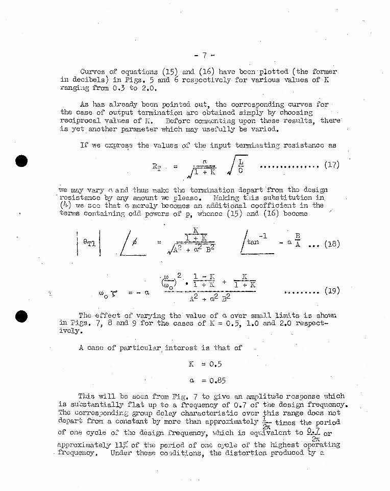
Ourves of equations (15) and (16) have been plotted (the former in decibels) in Figs. 5 and 6 respectively for various values of K ranging from 0.3 to 2.0.
As l~s already been pointed out, the corresponding curves for the case of output termination are obtained simply by choosing reciprocal values of K. Before commenting upon these results, there is yet another parameter which may usefully be varied.
If we expre~8 the values of the input terminating resistance as
('I,
== AI ~ .............. 0 • (17)
we may vaxy cr. and thus make the termination depart from the design 'resistance by any amount we please. 1ilaking tilis substitution in (4) we see that a merely becomes an additional coefficient in the terms containing odd powers of p, whence (15) and (16) become
K
I -1 .~ tan __
B a A _ •• (18)
K + l~K
•.•••• .; • _ (19) - - a
The effect of varying the value of a over small limits is shown in Figs. 7, 8 and 9 for the cases of K == 0.5, 1.0 and 2.0 respectively_
A caso of particulax, interest is that of
K == 0.5
a = 0.85
This 'will be seen from Fig. 7 to give an amplitude response which is substantially flat up to a frequency of 0.7 of the design frequency. The corresponding group del~ characteristic over this range does not depart from' a constant by' more tr..an approximately ~ times the period of one cycle of the design frequency, which is equivalent to 9_-1. or
27t apprOXimately l11b of the period of onc cycle of the highest operating
. frequency. Under these cortdi tions, the distortion produced by a
- 8 -\
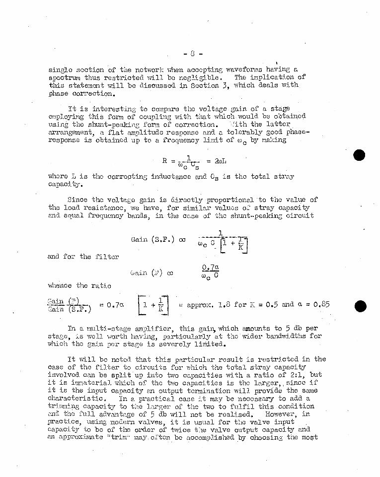
single section 'of the network when accepting waveforms having a spectrum thus restricted will be negli gi ble. The implication of this statement will be discussed :i,n Section 3, which deals with phase correction.
It is interesting to compare the voltage gain of a stage employing this form of coupling with that vvhich would be obtained using the shunt-peaking form of correction.iith the latter arrangement, a flat amplitude response and a tolerably good phaseresponse is obtained up to a frequency Hmi t of (')c by maldng
R = --~ = auL Wc s
whore L is the correpting inductance and Cs is the total stray capacity.
Since the voltage gain is directly proportional to tho value of the load resistance, we have, for similar values of stray capacity and equal frequency bands, in the case of the shunt-peaking circuit
Gain (S.P.) ex::
and for the filter
Gain (J1') cc
whence the ratio
~ .. -tf1:1.~ Gain S.P. ) = 0.70., ~ + tu ~ approx. 1.8 for J[ ~ 0.5 and " - 0.85
In a multi-stage ai11.?lifier, this gain, which amounts to 5 db per stage, is well worth having, particularly at the vvider bandwidths for which the gain per stage is severely limited.
It vdll be noted that this particular result is restricted in the case of the filter to circuits for vvhich the total stray capacity involved can be apH t up into two capacities with a ratio of 2:1, but it is immaterial which of the two capacities is the larger, \ since if it is the input capacity 8Xl output termination will provide the same characteristic. In a praotical case it may be necessary to add a trimmip.g capaci"bJ to the larger of the tvyO to fulfil this condi tion i.U1d the full aa.vantage of 5 db will not be roalised. However, in practice, using modern valves, it is usual for the valve input capaci ty to be of the order of tvace the valve output capaci"bJ and an approximate iitrim" may of ton be accomplished by choosing the most

;;.. 9 -
suitable position for the grid coupling condenser, as shown in Figs. 10 (a) and (b). ~n the other hand, when coupling the output of a power valve to the grid or cathode of a C.R.T. for modulation purposes, it is common to find that the valve output capacity, with associated strays, is of the order of twice the C.R.T. input capaci~, and in this case the desired characteristic is obtained wi th an input termination •
. Another response curve of interest is the case of K = 1, a. = l. (Fig. 8). This is simply the case of the Hconstant kll symmetrical filter, and the response, which rises slcwlY to a maximum of + 4.0 db at approximately 0.8 of the cut-off frequency, is useful for providing a small amount of "top-liftii to compensate for other deficiencies, .for example, aperture distortion. Larger degrees of high-frequency correction may be obtained by using a value K = 2, end values of a. <1.0.
3.1 ?.!'actica]. COE...sJ-derat~_.5ms~
Undoubtedly the most important present day application of videofrequency amplifiers is in the provision of amplification for teleVision signals, and in this section we shall base our discussion in tenil's of such signals, and concentrate particular attention on the unit step waveform, which in teleVision corresponds-to the sudden transition from a black to a white area or vice versa.
T.C.,Nuttall has already made a comprehensive study of phase equalisation, and a paper by h:i.tJ. dealing viii th this subject livaS
presented at Zurich, in September 1948 (4). Vie sh<:':1.11 review the question here, briefly, since it has considerable bearing on the choice of intervalve couplings.
In the previous section it was shown that the characteristic of a coupling filter wluch has the parameters K = o.~ and a. = 0.85 (see F'ig. 8) is such that a sic;nal will be transmitted through the filter with negligi.ble distortion, provided the spectrum of the signal is limited to a maximum frequency, wc, equal to 0.7 of the design frequency, wo. If, however, a unit step sic;nal, obtained, for ey,ample, from an ideal camera, is applied to the filter without any modification to its, spectrum, the output we should obtain would be of the form shown in j 1ig. 11 (a), and if several stages employing similar couplings were used in cascade, due to the increased rate of mlt-off and the more rapid departure from a linear phase characteristic near the cut-off frequency, the output waveform would be even more distorted and of the form shown in ]]'ig. 11 (b). ,such response waveforms vVQuld, of course, only be acceptable for television, in cases where the cut-off frequency, 'tO c, was arranged to be greater than the frequency corresponding to the limiting optical resolution

- 10 -
of the reproducing system. In otl1e:c "{vords, if the pattern produced by the distortion could not be resolved by the reproducing screen, then the distortion would be of no consequence.
It is eq'L1.ally obvious that if the television camera was not capable of resolving the fonn of a similar pattern, the distortion vrould not exist since the spectrum of the camera output signal. would then be confined to within the cut-off limit of the filter, over which ranse we may re!];ard the filter as distortionless.
This in effe'ct sayinG that it is not permissible to int~oduce a sharp cut accompanied by phase distortion into the video . ';
, characteristic except at a frequency higher than that y{hich corresponds to the finest detail w'hich the electro-optical elements of the syst~n can resolve.
l:et us consider what this means in terms of a 4D5-line system of television. If detail corresponding to 405 lines in the horizontal direction is to be reproduceo. vvi ti10Ut severe loss of contrast ratio,' El. video frequency choracteristic is required which is substru1.tially flat up to El. limit of approximately 3.0 :,c/s. Since it is not pemissible to introduce a sharp cut at this limi tinG frequency by means of straightforv{ard filters, the complete electrical system should be a,esigned to have a considerably -:vider bandwidth than this, say 5 l'Ic/s, whether a sharp cut-off or a trailing characteristic is used, and, rememberirlG that in practice the electrical system includes the complete transmi tti:ag and receiving apparatus, the requirement is most uneconomical.
I
iil.s anal ternative it miGht be argued that the whole of .the electrical system following the camera tube could be designed to have a cut-off frequency of' a little over 3.0'l:ic/s, and that cut-off I
distortion could be avoided by confining the spectrum of the camera output signal' to within this 1il!.1i t. Since, however, we require that the response from the cmnera should be substantially unattenuated at 3.0 Mc/s, this could only be achieved by mea.ns of a filter with a very sharp cut-off, which would of course result in the very distortion we are endeavouring to avoid. On the other hand, to limit the speotrum of the camera output siGnal by means of a gradual cut-off imnlies that the attenuation must commence at a relatively low frequ~ncy, say 1.0 L:c/s, .9nd increase steadily up to the Hmi ting frequency of 3.0 = "C/3 J the re suI t of which will be to cause a considerable deterioration in definition.
All this is true whcn the eloctrical characteristic is determined by n1efJns of' conventional filters without phase correction. If', however, a phase equalising network is introduced into the electricaJ. system, so that at the output of' the system all components over the pass band arJ."ive with a constant delay, i.e. the

- 11 -
overall phase characteristic is linear, a different state of affairs Ylill exist.
Olearly in such circumstances any symmetrical function, whether odd or even, will remain a sYmmetrical function since only the amplitudes of the components of its spectrum will have been modified, and in the limit for an infinitely sharp cut-off, the viTaveform resulting from D. unit step input will be of the form shov1l1. in Fig. 12. It is a simple matter to show that the resulting time function is in this case the sine-integral function for which the over-shoot is less than lOjG, an amount which is scarcely perceptible when viewed on a television screen. l"or any slower rate of cut-off, the overshoot will be less than thIs, and the waveform of :B' ig. 12 is therefore representative of the worst case •.
It will be noted from PiS. 12 that the arrival of the "stepil is anticipc,ted by ripples which appear in the waveform prior to the time, to, at which the step actually occurs. This does not, of coursG, imply that the ripples occur before the step has been ~££li~ to the filter, but Simply that the phase-equalising network must necessarily introduce a time delay in order to produce the desired effect of advancing the arrival time of the high frequency components .r~1:..~l!.o.. to that of the low frequencies.
To obtain precise phase-equalisation of any practical filter would require an infinite number of sections in the equalising network, and the delay through the equaliser would thus be infini te. This is obviously true, since if the output waveform due to unit step input is to possess perfect odd s~nmet~, the ripples must commence at a time - 00 relative to the actual step and an infinite delay is thus a necessary' pos tula te. In practice, a delay equal to. the period of two or three cycles of the cut-off frequency is sufficient to provide SUbstantial s~etry and an equaliser having four sections is usually adequate,
By means of phase-equalisation it is, therefore, possible to obtain a transient response '\,11.ich is satisfactory for television purposes, even though the cut-off frequency of the electrical system is chosen to equal the frequ~ncy which corresponds with the finest detail which it is required to resolve.
A. most convenient i'onn of phase-eque.lising section is the bridged aT:' equivalent of the "al1-pass lt constant resistance lattice structure, as shovll1 in 1:1ig. 13 (a). The parameters of such a section may be defined ['cs follows:-
o ==

- 12 -
where :G, 0 C\,nd Ro are as shown in }ig. 13 (a) and f3 is a design constant which determines the equalising characteristic.
'de thus have,
R 2 ·0
::: L ei 2
and Wo
Since the netvfork has an all-pass characteristic, the only . significance', of Wo is that it is El. design frequency 'which "vill determine the range over which a given phase characteristic will be obtained.
Por a given ternlination and design frequency the only variable parameter is p and the transfer constcUlt may be expressed as
8 ::: 1.0
Differentiating the argument with respoct to 0J vve obtain for the normalised group delay
2 13 G + (;-)~ '_ 0_
Ourv(js of this expression nr0 given in :~,lig. ILl- for values of (3 ranging from p ::: 0.3 to ~ ::: If-.O.
It vdU be noted tint for vnlues of 13<1.0 the incluctance in the shunt element is negative and is therefore provided by mutual coupling betvveon the two inductances in the' series element, as shown in Pig. 1.3 (b).. If the coupling factor, k, is expressed in tOI'J:ns of (3 we obtain
The process of dcsigninC a phase equaliser for correcting a gi ven filter characteris tic is unavoidably tedious. Assuminz that the group delay characteristic of the filter is knovm, the simplesy method is to tlcombine!! various equalising characteristics by trial

r ~ /
- 13 -
and error, usin,0',' the curves of T~irr 11(. until a satisfactory .... ..... ..,;:,). , compensating characteristic is obtained. By a suitable choice of 0'>0' the working range of each section may be made to coincide with allY desired frequency band, and for Q complete equaliser the value of (»0 is not necessarily the same for all sections.
A useful combination which may be used as a basis for equalising most forms of L.P. filter is tviTO sections comprising
1 1 one (3 = '2 and one (3 = J2'"
The combined characteristic is shovvn dotted in Fig. 14 and 'will be seen to. provide a delay in the arrival time of frequency components which is at first gradually and then rapidly reduced as the frequency is increased.
A systematic approach to the design of simple ~ section intervalve coupling filters has been described and the general question of pha'se-equalisation has been discussed. It is considered that video fre~lency amplifiers involving many stages maY be designed most efficiently and simply by using these filters throughout and applying overall phase correction by means of a phase-equalising filter,
(H.L. Kirke)
- 14 -
(1) Por EX8.mple:
;;Principles o:~ i'elevision EngineerinsOi, D • c.~ • :~) inJ:: , Ohapter VI, Sect • .311-, pp. 226-227.
;;Radj.o :~2ineer' s Handbook ll ,
I' .ii:. Terrnan, Sect. 5, Par. 16.
(2) ,;', '1 de Band P .. x,1plificr for TeleVision\ :~ •. A. ",Iheeler, froc. LB..JP., July 1939, pp. 429-':-38.
(.3 ) "Transient Response ';, l;al1mann, Spencel~ and Singer, l=>roc. LR.I:., =.:arch 1911-5, pp. 169-195.
(11_) "80me Aspeots of Television Ciroui t Tecl-mic;'ue: Phase Oorreotion and Gamma Correction", T.O. Nuttal1, Dull. Lss. Suisse Jnectr., Vol. 40, 1949, No. 17, pp. 615-622.
----------------
1-e3
-'---o--~---4--:----~t----J
INPUT TERMINATION.
GENERALISED EQUIVALENT CIRCUIT.
FIG.2.
L
I I I
C~--:"l C :':2.
T' CrJCI
€~: I
~~'~~-4'~--~~~
FIG .I.
FIG.4 ..
OUTPUT TERMINATION.
--1 c ~ eo (a.)
L..-------+-~~. ~_ L
CIRCUITS WITH IDENTICAL RESPONSE CHARACTERISTICS.
, FIG.3
-'---T ,RT'" i C i
K ..li. re e,o
'---""'----_--4-__ "'--+~-Q;;;. J _~ __ L Ch>') OUTPUT TERMINATION
Rl= C --r L..-.~_Ii~_~_'~--+-~ __ ~I--lt.-f)' ef
, (d) EQUIVALENT TO(o.) IFft-t
IT BBC FILTERS USED AS INTER-VALVE ~~
COUPLINGS.,

ISSUE 1
19·4·49
'0 ~~ ~E~ '-" OJ C RI ~ ... 1.- C B "-0 ~.~ ] -5 0 0
.:. '" Cl.
c
~ ;: ~
GI .s;; w
II't e-- u .- 0 .~ 4.J
c:U-og5 .g l\() l.. -5 .~ '" c 0 .~ L.
~.~ \:J R .~ ~ ~ E 0 ~~ p ~ .2 u _ 0 ..
~ « ....J w 0
, I Il. :::>
~ <.!)
0 w !!! ....J « ~ er 0 z
.!l
" Z
w 0
~ :J Il. ~ « w > ~ ....J w er
CJoT 7m#~~~ffiR~~~~ffi#~ili&lli*~~ftm~~imtt~illffmttilltti*Emffi
6
5
4
3
2.
+4
~Q) ~ ~'-5 j';L~O
~:g .. C co AMPliTUDE AND GROUP-DELAY CHARACTERISTICS FOR VARIOUS VALUES OF oD..o .... 2
M ... ~
~-5g['~
BBC 7T CTION USED AS INTER -VALVE FILTERS C rS.No.2.

ISSUE 1
19 - 4-- 4-9
+2
0 ~ -c ~ -2 lLI 0
~ -4 :::; (L
~ -6 « w ~ -8 ~ .J .., Et -iO
rt !f. I
t-I,~
1"0 -+
:;.r
4~
~W it"
fr-i
~{jf I"~'
tL;+:
Wl ri;ti ::i i,;" I
Ij~, I"i'
Wfi I-!·~q- tj.
0,4 0'6 0·8 -- 102 c.J
FIG 7-130
AMPLI TUDE AND GROUP-DELAY CHARACTERISTICS WITH CHANGE OF oc:. FOR K: 0·5
UNSYMMETRIC 1r SE TI BBC FfL TERS USED AS INTER-VALVE
CO L
•

ISSUE L
\9 -4- 49
BBC
-G
o
;~" '""
0-4
FIG 8. AMPLI TUDE AND GROUP-DELAY CHARACTERISTICS WITH
CHANGE OF cc FOR K = 1.
UNSYMMETRI " ..". TI FILTERS USED AS INTER-VALVE
~..,.--I eou INGS.

ISSUE 1
BBC
·FIG 9.· AMPL~TU[)E.· AND GROUP DE:LAY CHARACTERISTIGS 'WITH
CHANGE' OFoc FOR .K~2.
UNS FILTERS .024 .
7. SH EE':TS. No.5

1·5
0·5
Ro-
0
I , , , I I -,
: c : c::~~:!:.~ . C~.::':, c_-:,)
: I I ' , I I I
, I
C c::'::, K ,:=,:"
I I
I I
c~:)c c.:;:)
I - I
I I
(b)
, , , c..~_J c.:::.:. ':~~c;i1~.J
: K I
SHOWING HOW POSITION OF GRID-COUPLING CONDENSER MAY BE CHOSEN TO ASSIST" TRIMMING."
FIG.IO.
'-5 "5
0-5 o-s
0 -t--+ -t-+ (0..) . (b)
FIG. 11. FrG. 12 .
~~--ho~oC'LJ ~ '-foooo'-=L
'- y - j!,-- y <" - L - _u L
"1 ~~ I =' L 2 COUPUNG FACTOR
-k,-' -fo'i!
o~ _________ ~I~2_C _______ -_I~_~~' 0
~2_1 L --
2 R£, re 0
(0.) FIG.13.
(b)
UNSYMMETRICAL ;r SECTION BBC FILTERS USED AS INTER -VALVE ~"..:.:~~~ REPORT.
COUPLINGS. T.024 7SHEET.5. No6

the British ''SroadcaSting Corporation and may •••. . •. ~ I
not be reproduced or disclosed to a third '-'-'-:"~------~'-"'-'--'.---'-.~ .-.• -- '. . C!
This drawing 'specificatiOn is the property of ,·· .. ·_··T"·· --"--·--]~~;""·-"_-·~V'J":.'ll. p~rty in any form without the written ·per. . 1 ~ f'n ~ missio(l of the Corporatiorl. . lD. : I--J...-_---!'--___ ~ _________ L_ ________ _,_-.------.• ----L....-..---------' .. _._ ...... . I
.:!J Ci ITI(J) ::0-< (f)~ ~ G)
n CITI ~. O~~ c
1)
CO- I '0
-0 rr1
r»r r » -(I) -<
~-~ () :r: Z » --t. i ",(1) 'n :0 '-i
I IT1
.~- ~ V') ->0 -f
~Z ()
0 ITI ."
~ 1;; IT1
1"1 0 ~.
...J C (JIrl iU
V') ", I· III ::0 1110
~I\J !Jl~ ~ '"
z 0 ;n ~ » r
' . 'ji, .. '0:: -n " _ (i)
.G)'~ . C ---0 ~~
~
f ~
o 0-2. 0-6 0-8
5
I' 2.
'C"T ,~;··t
!,,'O: 'f"' ""fr~
le: Lt h-~~.;:it '.
. .,