l national transportati safety board
TRANSCRIPT

1 .
I
. '
00 c N TSB - AAR d0/10 c .5
r i-
L
NATIONAL TRANSPORTATI SAFETY BOARD
WASHINGTON, D.C. 20594
AIRCRAFT INCIDENT REPORT
AEROMEXICO
OVER LUXEMBOURG, EUROPE NOVEMBER 11,1979
DC-10-30, XA-DUH
-
WTSB-AAR-80-10
C* s
.(
UNITED STATES GOVERNMENT

7 ,
1 I
I i
1,
TECHNIC 1. Report NO. 2.Government Accession No.
4 . T i t i e and S u b t i t l e Aircraft Incident Report- NTSB-AAR-80-10
AEROMEXICO DC-10-30, XA-DUH, Over Luxembourg, Europe, November 11, 1979
7 . Author(s)
9. Performing Organizat ion-Name and Address
National Transportation Safety Board Bureau of Accident Investigation Washihgton, D.C. 20594
12.Sponsoring Agency Name and Address
NATIONAL TRANSPORTATION SAFETY BOARD Washington, D. C. 20594
15.Suppiementary Notes
REPORT DOCUMENTATION PAGE 3 . R e c i p i e n t ' s Cata log No.
5.Report Date
6 .Per forming Organ iza t ion
3 . P e r f o r m i n g Organ iza t ion
November 7. 1980
Code
Report No.
10.Work U n i t No. 2998
i i .Contract or Grant No.
13.Type o f Report and Per iod Covered
Aircraft Incident Report November 11, 1979
14.Sponsoring Agency Code
I 6 . A b s t r a c t
McDonnell-Douglas DC-10-30 aircraft, entered a prestall buffet and a sustained stall OV( Luxembourg, Europe, a t 29,800 ft while climbing to 31,000 f t en route to Miami, Florida, fro]
performed an inflight functional check of the aircraft and, after finding that it operat€ Frankfurt, Germany. Stall recovery was effected a t 18,900 ft. After recovery, the cre
properly, continued t o their intended destination.
About 2138, on November 11, 1979, AEROMEXICO, Flight 945, XA-DUH,
After arrival a t Miami, Florida, i t was discovered that portions of both outboar
no injuries to the 311 persons on board Flight 945. No injuries or damage to personnel (
elevators and the lower fuselage tail area maintenance accew door were missing. There wer
property on the ground was reported.
Visual meteorological conditions prevailed a t the time of the incident.
The National Transportation Safety Board determines that the probable cause of th incident was the failure of t h e flightcrew to follow standard climb procedures and t adequately monitor the aircraft's flight instruments. This resulted in the aircraft entering int a prolonged stall buffet which placed the aircraft outside the design envelope.
1 7 . Key Words 1 8 . D i s t r i b u t i o n Statement This document is available t o the public through the National Technical Informatic
Springfield, VA 22161 Service,
1 9 . S e c u r i t y C l a s s i f i c a t i o n 2 2 . P r i c e 2 i . N o . of Pages 2 0 . S e c u r i t y C l a s s i f i c a t i o n ( o f t h i s r e p o r t )
UNCLASSIFIED (o f t h i s page) UNCLASSIFIED 32
NTSB Form 1765.2 (Rev. 9/74)

CONTENTS
SYNOPSIS . . . . . . . . . . . . . . . . . . . . . . . . . . . . . 1 1
1.1 History of Flight . . . . . . . . . . . . . . . . . . . . . . . . . 1 1.2 Injuries to Persons . . . . . . . . . . . . . . . . . . . . . . . . 4 1.3 Damage to Aircraft . . . . . . . . . . . . . . . . . . . . . . . . 4 1.4 Other Damage . . . . . . . . . . . . . . . . . . . . . . . . . . 4
4 1.6 Aircraft-Information . . . . . . . . . . . . . . . . . . . . . . . 4 1.7 Meteorological Information . . . . . . . . . . . . . . . . . . . . . 7 1.8 Aids to Navigation . . . . . . . . . . . . . . . . . . . . . . . . 7 1.9 Communications . . . . . . . . . . . . . . . . . . . . . . . . . 7 1.10 Aerodrome Information . . . . . . . . . . . . . . . . . . . . . . 7
7 1.12 Aircraft Examination . . . . . . . . . . . . : . . . . . . . . . . 10 1.12.1 Structures . . . . . . . . . . . . . . . . . . . . . . . . . . . 10 1.13 Medical and Pathological Information . . . . . . . . . . . . . . . . 12 1.14 Fire 12 1.15 Survival Aspects . . . . . . . . . . . . . . . . . . . . . . . . . 12 1.16 Test and Research . . . . . . . . . . . . . . . . . . . . . . . . 1 2 1.16.1 Powerplant . . . . . . . . . . . . . . . . . . . . . . . . . . . 1 2 1.16.2 Metallurgical Examination . . . . . . . . . . . . . . . . . . . . 12 1.17 Other Information . . . . . . . . . . . . . . . . . . . . . . . . . 13 1.17.1 Autopilot and Flight Director Engagement Modes; Operation . . . . . 13 1.17.2 Autothrottle Speed Control System (AT/SC) . . . . . . . . . . . . 16 1.17.3 Stall Warning . . . . . . . . . . . . . . . . . . . . . . . . . . 17 1.17.4 Climb Operations with the Flight Guidance and Control System . . . . 17 1.17.5 Structural Certification Tests and Analysis . . . . . . . . . . . . . 17 1.17.6 Applicable Federal Regulations . . . . . . . . . . . . . . . . . . 18
1 . Factual Information . . . . . . . . . . . . . . . . . . . . . . . . .
1.5 Crew Information . . . . . . . . . . . . . . . . . . . . . . . . .
1.11 Flight Recorders . . . . . . . . . . . . . . . . . . . . . . . . .
. . . . . . . . . . . . . . . . . . . . . . . . . . . . . . .
2 .ANALYSIS . . . . . . . . . . . . . . . . . . . . . . . . . . . . . 18 $ 1 'r
3 .CONCLUSIONS . . . . . . . . . . . . . . . . . . . . . . . . . . . 22 3.1 Findings . . . . . . . . . . . . . . . . . . . . . . . . . . . . . 22 3.2 Probable Cause . . . . . . . . . . . . . . . . . . . . . . . . . . 23
4 .SAFETY RECOMMENDATIONS . . . . . . . . . . . . . . . . . . . . 23 1
5 .APPENDIXES . . . . . . . . . . . . . . . . . . . . . . . . . . . 25 i Appendix A-Investigation and Hearing . . . . . . . . . . . . . . . . . 25 1 Appendix B-Personnel Information . . . . . . . . . . . . . . . . . . 26 1 Appendix C-Aircraft Information . . . . . . . . . . . . . . . . . . . 27 Appendix D-DFDR Data Graph for Altitude. IAS and Heading . . . . . . 28 Appendix E-DFDR DataGraph for Altitude. Pitch and Roll . . . . . . . Appendix F-DFDR Data Graph for Altitude. Elevator. Rudder
29
1 1 'i 'I
and Aileron . . . . . . . . . . . . . . . . . . . . . . 30 Appendix G-DFDR Data Graph for Altitude. N1 for All Engines . . . . . . 31

J 7
I
NATIONAL TRANSPORTATION SAFElY BOARD WASHINGTON, D.C. 20594
AIRCRAFT INCIDENT REPORT
Adopted: November 7,' 1980
AWOMEXICO DC-10-30, XA-DUH
OVER LUXEMBOURG, EUROPE NOVEMBBR 11,1979
SYNOPSIS
About 2138, on November 11, 1979, AEROMEXICO, Flight 945,
sustained stall over Luxembourg, Europe, a t 29,800 f t while climbing to 31,000 ft XA-DUH, a McDonnell-Dotlglas DC-10-30 aircraft, entered a prestall buffet and a
a t 18,900 ft. After recovery, the crew performed an inflight functional check of en route to Miami, Florida, from Frankfurt, Germany. Stall recovery was effected
the aircraft and, after finding that it operated properly, continued to their intended destination.
After arrival a t Miami, Florida, it was discovered that portions of both outboard elevators and the lower fuselage tail area maintenance access door were
or damage to personnel or property on the ground was reported. missing. There were no injuries to the 311 persons on board Flight 945. No injuries
Visual meteorological conditions prevailed a t the time of the incident.
cause of this incident was the failure of the flightcrew to follow standard climb The National Transportation Safety Board determines that the probable
procedures and to adequately monitor the aircraft's flight instruments. This resulted in t he aircraft entering into a prolonged stall buffet which placed the aircraft outside the design envelope.
1.1
1. FACTUAL INFORMATION
History of the Flight
On November 11, 1979, AEROMEXICO, XA-DUH, Flight 945, a
between Frankfurt, Germany, and Mexico City, Mexico D.F., with an en route McDonnell-Douglas DC-10-30 aircraft, was operating as a charter passenger flight
refueling stop at Miami, Florida. About 2119 G.m.t., 1/ AEROMEXICO 945 departed Frankfurt, Germany, on an instrument flight rul% (IFR) flight plan to
boerd. Miami; 295 passengers, 3 flightcrewmembers, and 13 flight attendants were on
- 1/ All times herein are Greenwich mean, based on the 24-hour clock, unless otherwise noted.

-2-
and the initial portion of the en route climb were uneventful. A t 1,500 f t According to the crew, the aircraft preflight, engine start, taxi, takeoff
aboveground level, with the captain a t the controls, the crew engaged the No. 1 autothrottle system (ATS) and selected the N 2/ mode. The captain requested permission from air traffic control (ATC) to himb a t 283 kns 3/ the appropriate speed for the heavy weight of t h e aircraft. The captain stated {hiit he continued to control the aircraft manually to 10,000 f t with both flight directors (FD) in the FD position. However, upon climbing through 10,000 ft , the ATS speed selector was positioned to 320 kns and the flight director/autopilot (FD/AP) was programed to have the 'AP fly the aircraft in the indicated airspeed hold mode (IAS Hold) with the No. 1 AP engaged in the command (CMD) position. The thrust rating computer (TRC) was set a t climb power.
?While climbing through 14,000 feet m.s.l., the AP became disengag c @r
The captain reengaged i t by positioning the No. 1 AP lever to the CMD position and then pressed the inertial navigation system (INS) selector in the heading (HDG) panel. No other FD/AP modes were reselected. The pilot commented to his crew that if the AP disengaged again, they would write i t up in the aircraft logbook.
>,.*> , Y "
According to t h e crew, while climbing through 27,500 f t about 100. miles west of the departure airport, they fel t a vibration which, within seconds, increased in intensity. The crew suspected an abnormal vibration in engine No. 3 and elected to reduce its power and then to shut it down. The crew also stated that, upon reducing power on engine No. 3, t h e aircraft assumed a pitch down attitude, the AP became disengaged, and the aircraft rolled to the right and then to t h e left and started to lose altitude.
engine power was reduced, the aircraft decelerated into speeds that were below The Digital Flight Data Recorder (DFDR) revealed that, after the No. 3
the stall buffet speed and the design flight envelope. Shortly thereafter, the nose dropped and the aircraft entered into a stall while a t 29,800 f t and an IAS of 226 kns.
The calculated stall speed for the flight a t the time of the occurrence was 222 kns. The calculated buffet onset speed was about 241 kns. The DFDR showed a constant rate of climb until the stall and loss of altitude occurred. It also showed that the airplane noseup elevator was held between 9' and 18.2' throughout
recovery from the stall starting at about 24,500 ft . most of the recovery maneuver until the elevator was gradually relaxed with
The captain said that as the aircraft nose dropped, the spoilers were deployed to arrest the impending overspeed condition that could have been created
system became active. The DPDR readout showed the recovery started a t 23,900 by the aircraft's nose low attitude. About 10 seconds later, the autoslats extend
ft. A t that time, the airspeed increased to a value above the calculated stall speed. The vertical acceleration reached a maximum of 1.68 g's during the recovery process which ended a t an altitude of 18,900 f t , and the crew regained full control of the aircraft about 18,000 ft . According to the crew, when aircraft
- 2/ Engine fan speed percent indicator. - 3/ The maneuvering speed of the aircraft with flaps and gear up, designated as VA.

-3-
i
control was lost, the first officer declared an emergency. During that period, the DFDR showed that the aircraft was responding in a normal manner to crew control inputs.
announced a "Mayday" and loss of control a t 31,000 f t while flying in an area 20 According to French ATC officials, a t 2143 AEROMEXICO Flight 945
nmi from Chatillon, France, (CTL) VOR. The pilot advised that he was executing an emergency descent. Later, he advised that he had regained control of the aircraft a t 19,000 f t and requested permission to divert to Madrid, Spain. French ATC authorized the flight's diversion.
engine No. 3. It appeared to be functioning normally with all parameters indicating Shortly after recovering control of the aircraft, the crew airstarted
within normal limits with no indication of vibration.
noted during the entire flight other than the autopilot becoming disconnected while The crew stated that there was no malfunction or failure of any system
climbing through 14,000 f t m.s.1. and the vibration, which was suspected as emanating from engine No. 3.
configured with the left pumps feathered and the right pumps on for each engine; According to the flight engineer, the aircraft hydraulic system was
the motor-pumps were in the armed position. A t no time did he detect a hydraulic low quantity or low pressure condition. After regaining control of the aircraft, the flight engineer assessed the conditions in the aircfaft and found only a few ceiling panels in t h e passenger cabin detached. A functional test of all systems pertinent to the flight control systems and flight guidance system was completed by the crew with satisfactory results.
normally and since a landing at Madrid would require dumping 140,000 pounds of The captain stated that since all systems appeared to be functioning
fuel he elected to continue the flight to Miami, Florida. According to French ATC, shortly after issuing clearance to Madrid, the flight requested and received clearance to proceed to Miami.
The flight climbed in visual meteorological conditions to 28,000 f t and
kns) in an ambient temperature of international standard atmosphere (ISA) +go C then to 31,000 ft , ending a t 33,000 ft near Bermuda while cruising a t Mach .E2 (385
(static air temperature -41" C). The flight landed at Miami, Florida, on November 12, 1979, a t 0705 without any further problems.
Upon arriving at the passenger terminal gate, the captain requested that maintenance personnel give the aircraft a visual exterior inspection. It was found that about 4 f t of each outboard elevator tip, including the corresponding counterweights and the aircraft's tail area lower access door were missing.
The aircraft was grounded a t Miami, Florida, where it underwent a detailed inspection, a thorough examination, and a functional test of all flight control systems, ATS, AP/FD, engine No. 3, and all other related systems that could have induced the condition experienced by the crew during the incident. No discrepancies were noted.

-4- '1
The aircraft's left and right outboard elevator and the fuselage tail .,!
lower area access door were replaced and the aircraft was flown to Mexico City, ! on November 16, 1979, where it again went through a detailed inspection in I accordance with AEROMEXICOIs Approved Inspection and Maintenance Program. No discrepancies were found during the examination and testing of the aircraft. Later, it was released for scheduled line flight operations.
i 1.2 hjuri€s to Persons 1
I
* There were no injuries to persons. I
1.3 Damage to Aircraft
The aircraft damage was confined to both aircraft outboard elevator tips and related counterweights and t h e tail lower area access door. (See figures 1 and 2.)
1.4 Other Damage
There was no other damage.
1.5 Crew Infamation
and Mexican Government regulations. The flight crewmembers had successfully All flight and cabin personnel were qualified in accordance with ICAO
completed an AEROMEXICO approved training program for DC-10 aircraft. (See appendix B.)
the flight. All crewmembers had been off duty for 24 hours before reporting for
1.6 Aircraft Infamation
certificated, maintained, and equipped in accordance with current Mexican XA-DUH was owned and operated by AEROMEXICO. It was
Government regulations and ICAO standards.
Frankfurt, Germany, showed that the aircraft had a zero fuel weight of 324,831 The aircraft weight and balance documentation for departure from
pounds and a load of 230,383 pounds of jet fuel. Its maximum allowable certificated gross weight was 555,000 pounds. Its takeoff gross weight w8s 555,096 pounds and its center of gravity (c.g.) was 17.6 percent. The critical engine failure speed (Vl ) was 170 kns; the rotation speed (V ) was 180 kns; the takeoff safety speed (V,) was 189 kns; and the maneuvering spied (V,) was 283 kns.
To meet the second segment climb rquirements, the aircraft departure
reduced power a t maximum certificated gross weight. The reduced power was used on runway 25R a t Frankfurt was limited to 6.9 of wing flaps for a takeoff with
fw engine and fuel conservation purposes. The aircraft had to accelerate to 283 kns, design maneuvering speed (VA), to maneuver on course at the departure takeoff gross weight.

-5-
i
Figure 1.--View of left outboard elevator tip.

-6-
i
Figure 2.--View of right outboard elevator tip.

-7-
t
I
engine/hour, i t was estimated that t h e aircraft engines burned about 11,000 pounds A t an average consumption of about 11,000 pounds of fuel per
of fuel from the time of departure to the time of the incident, which reduced the aircraft gross weight to an estimated 544,000 pounds.
1.7 Meteorological Information
Visual meteorological conditions prevailed a t the time of t he incident. Weather was not a factor in this incident.
1.8 Aids to Navigation
Not applicable.
1.9 Communications
There were no known communication malfunctions.
1.10 Aerodrome Information
The airport elevation is 368 f t m.s.1. Runway 25R is 12,795 f t (3,900 meters) long The Frankfurt/Main Airport (EDDF) is located a t Frankfurt, Germany.
and 197 f t (60 meters) wide, and it has a 0.25 percent upslope in that direction.
1.11 Flight Reccrders
The aircraft was equipped with a Sundstrand Digital Flight Data Recorder (DFDR) Model 981-6009, S/N 2632. The aircraft's DFDR was obtained from the airline officials and sent to Douglas Aircraft Company in Long Beach, California, 5/ where i t w a s read out under the supervision of NTSB investigators.
Although the entire flight was recorded on the DFDR tape, the data printout was limited to only the portion relating to the incident, between 21:37:04 and 21:44:08, and only 6 minutes 40 seconds of the recorded parameters were plotted. (See appendixes D through G.) The parameters included in the printout
aileron, horizontal stabilizer, spoiler and slat positions, vertical acceleration, were indicated airspeed, altitude, pitch and roll attitude, elevator, rudder and
positions were not operating properly. Vmo/Mmo, the aerodynamic load limits or engine thrust, heading, and vertical speed. The discrete functions recording slat
acceleration limits, were not exceeded during the incident.
the aircraft climbed through an altitude of 25,011 f t m.s.1. and ended when the The 7 minute 4 second period covered by the processed data began when
aircraft stabilized about 19,178 f t m.s.1. During the first 4 minutes 12 seconds, t h e aircraft climbed steadily about 1,200 f t per minute as the IAS decreased from 318 to 226 kns and the pitch angle increased from 4.5' to 11' noseup. This type of
from aircraft that are climbing in the FD/AP vertical speed (VERT SPD) mode. An climb profile is consistent with the type of profile expected in DFDR tape readouts
- 5/ The NTSB's readout station was being repaired at the time of t he incident.
-8-
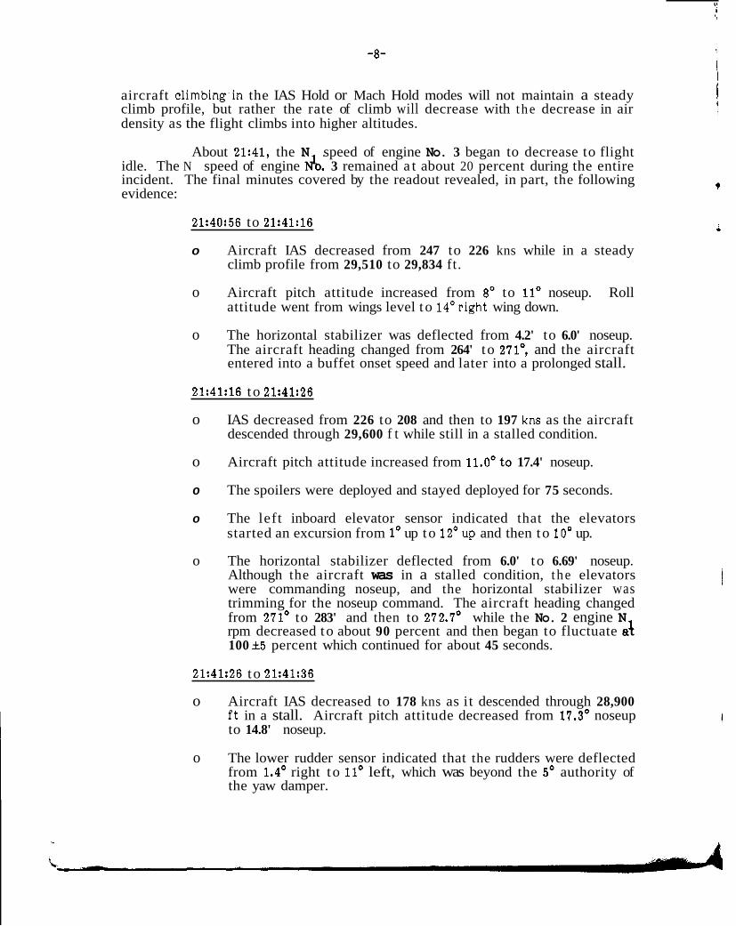
aircraft climbing.in the IAS Hold or Mach Hold modes will not maintain a steady climb profile, but rather the rate of climb will decrease with t he decrease in air density as the flight climbs into higher altitudes.
About 21:41, the N speed of engine No. 3 began to decrease to flight idle. The N speed of engine do. 3 remained a t about 20 percent during the entire incident. The final minutes covered by the readout revealed, in part, the following evidence:
21:40:56 to 21:41:16
o Aircraft IAS decreased from 247 to 226 kns while in a steady climb profile from 29,510 to 29,834 ft .
o Aircraft pitch attitude increased from 8' to 11' noseup. Roll attitude went from wings level to 14'right wing down.
o The horizontal stabilizer was deflected from 4.2' to 6.0' noseup. The aircraft heading changed from 264' to 2713 and the aircraft entered into a buffet onset speed and later into a prolonged stall.
21:41:16 to 21:41:26
o IAS decreased from 226 to 208 and then to 197 kns as the aircraft descended through 29,600 f t while still in a stalled condition.
o Aircraft pitch attitude increased from 11.0'to 17.4' noseup.
o The spoilers were deployed and stayed deployed for 75 seconds.
o The left inboard elevator sensor indicated that the elevators started an excursion from 1' up to 12'up and then to 10' up.
o The horizontal stabilizer deflected from 6.0' to 6.69' noseup. Although the aircraft was in a stalled condition, t he elevators were commanding noseup, and the horizontal stabilizer was trimming for the noseup command. The aircraft heading changed from 271' to 283' and then to 272.7' while the No. 2 engine N rpm decreased to about 90 percent and then began to fluctuate ai 100 - +5 percent which continued for about 45 seconds.
21:41:26 to 21:41:36
o Aircraft IAS decreased to 178 kns as it descended through 28,900 ft in a stall. Aircraft pitch attitude decreased from 17.3' noseup to 14.8' noseup.
o The lower rudder sensor indicated that the rudders were deflected from 1.4' right to 11' left, which was beyond the 5' authority of the yaw damper.
i

-9-
t l
o Vertical acceleration remained about .9-g loads. The elevators continued in an excursion from 10' up to 8' up and then t o 19' up.
o The horizontal stabilizer deflected from 6.69' noseup to 8.33'
o The aircraft heading changed from 272' to 274' and then to 272'. noseup.
The rate of descent was reduced from about 4,200 to about 600 f t per minute.
21:41:36 to 21:41:56
o The aircraft IAS decreased from 178 to 175 kns and then increased to 217 kns as the aircraft continued to descend through 25,600 f t a t about 10,156 f t per minute.
o 'The aircraft pitch attitude decreased from 14.8' noseup to 10.9' nosedown and then to about 6.6' nosedown.
o The roll attitude continued an excursion from 3' left wing low to 23.5' left wing low to 25' right wing low to 3' right wing low to 13' right wing low and then to 5' left wing low. The rudder deflected from 12O left to 3Oleft.
o Vertical acceleration changed from .9 to 0.65 to 1.0 g.
o The elevators oscillated from 17' up to 9' up and then to 16'up.
o The horizontal stabilizer deflected from 8.33' noseup to 9.46' noseup and then to 6.48'noseup.
o The aircraft heading changed from 272' to 264' and then to 278'
21:41:56 to 21:42:06
o The aircraft IAS continued to increase from 217 to 248 kns as the vertical speed continued to increase to 15,000 f t per minute rate of descent a t 23,300 ft. The aircraft vertical acceleration changed from 1.0 to 1.4 g.
o The elevators deflected from 13.7' up to 8.4' up as the stabilizer
from 278' to 276'. deflected from 6.48' noseup to 9.56' noseup. The heading changed
21:42:06 to 21:42:16
o The aircraft IAS increased to 267.5 kns as the vertical speed slowed to about 11,988 f t per minute while descending through 21,600 ft.

- -10-
o The aircraft pitch attitude started an excursion between 5.2' nosedown t o 5.7' noseup. The roll attitude went from wings level to about 5.7' left wing down.
o The vertical acceleration oscillated between 1.4 to 1.1 to 1.68 g (the highest g load experienced during the occurrence). The elevators changed from 8.4' noseup to near neutral as the horizontal stabilizer increased to 9.87' noseup. The aircraft heading remained nearly constant a t about 276'.
21:42:16 to 21:44:08
o The aircraft IAS decreased as recovery became evident through a
started about 21,600 f t and enaed in a level controlled flight decreasing rate of descent and coordinated maneuvers which
stall recovery in contrast with the sequence of events preceding about 18,900 ft. The sequence of events was appropriate for a
21:42:16 during which it appeared that the aircraft control inputs were correcting in the wrong direction for a stall recovery.
1.12 Aircraft Examination
1.12.1 S ~ u c t u r e s
systems, and aft fuselage. The slats were inspected, and no evidence of either The airframe was inspected with emphasis on the empennage, control
overload damage cr other defects was found. The damage to the empennage was localized in the outboard elevator tips and the adjacent stabilizer tip fairings. A f t fuselage damage was limited to the tail cone access door. The elevator control system from the surfaces through the actuators was rigged properly. Numerous cabin ceiling panels, light fixtures, and an oxygen mask had been dislodged; however, most of these had been reinstalled by the cabin crew.
(a) Horizontal Stabilizer and Elevators
Approximately 4 f t of t h e outboard ends of both outboard elevators were missing and had separated at almost identical locations. The approximate line of separation connected the trailing edge channel a t Station XE 436 to the elevator spar a t Station XE 455. The elevator outboard hinge fitting
separated with the outboard end of the elevators. Visual examination of the mounted on the elevator spar and the eyebolt mounted on the hinge fitting had
fracture surfaces on the elevator showed no indication of prior cracking. The fracture surfaces were clean and bright with smearing on some portions of the sheet metal surfaces.
the horizontal stabilizer sustained minor damage. Scrape marks a few thousandths The left outboard elevator hinge fail safe "A" frame attached to
of an in deep were evident in the bore and flange of the bushing. The outboard lug of the two lugs on the outboard hinge "A" frame was broken about 1 in forward of the elevator hinge line. The inboard lug was bent inboard approximately 1/8 in, and
t
-11-
f
1
the hinge line hole was elongated about 1/16 in. in an upward and aft direction. Caked grease surrounded an area approximately .090 in wide around the edge of the hinge hole. The horizontal stabilizer tip fairing had a buckle about 1/2 in deep and 4 in long just forward of the af t closing rib in the fairing. The aft edge of the fairing was bent outward about 1/8 in, and there was an impact mark on the fairing at this location.
The right outboard elevator outboard hinge fail safe "A" frame attached to the horizontal stabilizer was broken about 2 in forward of the hinge line. 'No indication of prior cracking was evident. The outboard lug of t he two lugs on the outboard hinge "A" frame was broken about 2 in forward of the hinge line. No indication of prior cracking was evident. The inboard lug was bent inboard about 1/2 in. A scrape mark approximately .005 in deep was observed on the outboard side of the inboard lug. The scrape mark extended from the edge of t he hinge hole to the upper edge of t h e lug. The horizontal stabilizer tip fairing had two small buckles about .060 in deep and 2 in long located just forward of the aft closing rib. The aft edge of the fairing was bent outboard approximately 1/16 in and an impact mark was evident on the aft edge of the fairing.
Both horizontal stabilizers sustained minor damage and
examination of t h e horizontal stabilizer box structure did not reveal any damage. deformation to the trailing edge panels a t t he outboard end. External visual
(b) Aft Fuselage
from the structure. The door frame in the area of the hinge had been cracked and The tail cone acces door, which opened to the rear, had been torn
the skin was torn and bent.
(c) Control Systems
The flight control surfaces (ailerons, elevators, rudder, spoilers, slats, flaps, and horizontal stabilizer) were operated through their full travel with
subjected to sharp step inputs with no problems observed. The entire hydraulic no motion abnormalities observed. The rudder, ailerons, and elevators were also
system was tested and found to be functioning properly. The surface position indicator and flap/slat instrument performed satisfactorily during the control system operation.
anomalies were observed. Each autopilot and flight director was engaged into the The flight directors and autopilots were operated and no
V/S, IAS Hold, Mach Hold, Turb and Altitude Hold modes in pitch, and was engaged in Heading Hold, Heading Select, and VOR modes in roll. The manual control wheel steering mode was also satisfactorily tested.
The elevators were deflected for aircraft noseup and aircraft nosedown using the V/S wheel; the ailerons were deflected using HDG SEL and VOR modes. The control surface deflections and authorities visually appeared correct and no oscillation or dithering was observed. Each AP was disengaged by operating each control wheel disconnect switch and the engage lever. The AP red flashing

-12-
disengage lights and engage lever operation were normal. Override forces were
Reversion to the “MAN” mode occurred in all cases. The overhead yaw damper applied in pitch and roll, to each column while each AP was engaged in CMD.
test was successfully performed with all four channels engaged. The automatic pitch trim was tested while the AP‘s were in the manual mode and pitch forces applied in both the ANU and AND direction. The stabilizer rate and direction appeared correct.
disconnect switches. Annunciation of the speed mode and the ATS flashing red The autothrottles were engaged and disengaged with the throttle
lights at disconnect were normal. The left and right stall test was performed and the stickshaker was actuated in about 5 seconds. The autoslat extend test was also performed. The slat disagree and slat reset light illuminated and the slats extended when the test switch was operated. When the slat reset switch was actuated, both slats retracted and the lights extinguished. When the required circuit breakers were closed and the appropriate switches were actuated to
pertinent “flags,” lights, and instruments operated normally. establish the aircraft in a configuration to perform the above functional tests, all
1.13 M e d i c a l and Pathological Information
Not applicable.
1.14 Fire
There was no fire.
-
1.15 survival Aspects
Not applicable.
1.16 Test and Research
1.16.1 Powerplant
Engine No. 3 was borescoped, and no evidence of distress, which would have caused a vibration in t he engine, was found. A visual inspection of the fan
of vibration. was performed, and no fan damage was found which would have caused a high level
1.16.2 Metallurgical EXamiMtion
inflight. Visual examination of the breaks, with a bench binocular microscope, The outboard ends of the right and left elevator panels had separated
disclosed overload characteristics in the hinge separations. The elevator panel separations contained appreciable mechanical damage to the fracture surfaces; however, in all areas that were not damaged, the features appeared typical of an overstress condition. No evidence of low load-high cycle fatigue was found an any break examined. The outboard elevator was checked and was found to conform to material specifications.
-13-
1.17 Other Information
XA-DUH is equipped with a flight guidance and control system (FGCS) which includes a dual autothrottle/speed control system (AT/SC), a dual flight
guidance computers provide intelligence to the autopilot and the flight director director (FD) system, and two dual channel autopilot (AP) systems. The flight
systems. The flight director system and the autopilot share many of the same modes, and the FGCS modes are selected in t h e same manner as the autopilot
provides the means of selecting and engaging the modes of operation. (See modes. The FGCS control panel, which is located in the center of the glareshield,
figure 3.) The mode annunciator panel and examples of the flight director, autothrottle, and autopilot modes displays appear directly above each pilot's
four separate displays in each annunciator unit: the autothrottle (AT) mode attitude director indicator and mach/airspeed indicator. (See figure 4.) There are
"Roll," "Pitch." 'Only those system controls and modes involved in this incident are annunciator and the three autopilot and flight director mode annunciators "Arm,"
discussed.
1.17.1 Autopilot and Flight Director hgngement M o d e q Operation
an autopilot lever is in the CMD position, both flight mode annunciators display the The basic engagement mode of the autopilot is "Command CWS." When
modes of the engaged autopilot. The basic engagement modes of the FD system are "Heading Hold" and "Altitude Hold," or "Vertical Speed" if the aircraft is climbing or descending. Overpowering the autopilot while in the CMD position will result in the autopilot lever dropping to the Manual (MAN) position, causing red, flashing, autopilot fail lights to come on. In the MAN position, the pilot utilizes the normal control wheel and column. However, because the autopilot is still engaged when the aircraft is placed in a particular attitude, i t remains in that attitude until another wheel or column input is applied. The response of the aircraft is proportional to the applied force and movement, but it is limited to
position, Command CWS is not annunciated and the flight mode annunciators will certain bank and pitch attitude angles. With an autopilot lever in the MAN
system modes are common to both the autopilot and flight director system, such as display the armed op engaged flight director modes. Certain flight guidance
"IAS Hold," "Mach Hold," 'Vertical Speed," and "Altitude Hold" for pitch. If the autopilot is disengaged while in one of these particular modes, t he flight director
CMD will place the autopilot in the previously selected FD mode if the flight will remain engaged in the selected FGCS mode. Reengaging the autopilot lever to
director is on, or into CWS (annunciated) if the flight director is off.
Hold" (IAS Hold) and "Mach Hold" (MACH) modes be used primarily to climb or to The manufacturer recommends that the autopilot "Indicated Airspeed
descend. The IAS and MACH pushbutton switches are seen on the flight guidance
"CMD," pressing one of these switches commands the autopilot to adjust the pitch and control panel below the autopilot levers in figure 3. With the autopilot in
pressed. The pitch mode window annunciates IAS Hold or Mach Hold depending on of the aircraft to maintain the airspeed or Mach existing when the switch was
which switch is depressed.

-14-
E * u)
al
m h

-15-
FLIGHT DIRECTOR, AUTOTHROTTLE AND AUTOPILOT MODES
lHROTTLES AUTO
T SPO
4LPHA SPO N1
RETD CLAMP
ARM
E A LT
VORIALT LOCIALT ILSIALT
LANDIALT VOR LOC
LAND 1 1 s
SNGL LANO DUAL-LAND
APP ONLY EICRS
INSIALT INS
BlCRS ALT
~~
ROLL I PITCH
S TAKEOFF
HOG HOLD CIA
HOG SEL
VOR CAP cws
VOR TRK
LOC CAP VOR CRS
LOC TRK ALGN
ROLL OUT
ElCRS CAP EICRSTRK
INS CAP
T TAKEOFF
CIA VERT SPD ALT CAP
ALT HOLD
MACH HOLD IAS HOLD
TURE CWS
G/S CAP GIS TRK FLARE
!
Figure 4.-Mode annunciator panel.

-16-
The vertical speed selector on the left side of the autopilot levers on the Flight Guidance and Control Panel, figure 3, is synchronized to the aircraft's
"Altitude Hold" (ALT HOLD) mode is engaged. When the vertical speed selector is vertical speed a t all times except when the "Vertical Speed" (VERT SPD) CT the
bars will move correspondingly and the pitch annunciator will display "ALT HOLD." manually rotated to the altitude hold detent, the flight director pitch command
The vertical speed selector wheel functions as an indicator or as a control. If the altitude hold mode has been engaged, the vertical speed selector wheel will remain in the altitude hold detent and will command "ALT HOLD." If the vertical speed mode has been engaged (either a climb or a descent), the vertical speed selector wheel will.remain in the selected position and will command a climb or a descent at the selected rate. When the "IAS Hold" or "Mach Hold" is engaged, the vertical speed selector wheel will automatically synchronize to the velocity of the aircraft.
1.17.2 Autothrottle Speed Control System (ATEX)
The FGCS includes a dual autothrottle and speed control system. The AT/SC panel provides the means for engaging either or both autothrottle systems
speed command for takeoff and go-arhnd as either a manual or automatic mode; and selecting either the "speed" or "N mode of operation. Its functions provide
the "speed mode," available in either manual or automatic, which permits the pilot to select a desired speed; Wpha speed" function which, if autothrottles are in the
lower speed is selected; and the N mode, which will automatically advance speed mode, will maintain or indicate t h e minimum maneuvering speed even if a
throttles to a N thrust limit (as deterhined from the mode selected on the Thrust Rating Computkr). The autothrottle speed mode provides protection against stall at all times, plus flap limit overspeed protection. The speed control system utilizes "Fast/Slow" indicators on the left side of each attitude director indicator (ADI) to indicate the relation of actual speed to selected speed. All engaged autothrottle modes are displayed on both the ATS flight mode annunciators. When autothrottles are operated in the speed mode and a speed is selected which is below the aircraft minimum safe maneuvering speed, "ALPHA SPD" will be annunciated to the pilots and the autothrottles will advance the speed to the minimum safe maneuvering speed. If the ATS is not engaged and a speed is selected in the speed readout that is below minimum safe maneuvering speed, the fast/slow indicators in the AD1 will be referenced to the minimum safe maneuvering speed (ALPHA SPD). The throttles are an integral part of the ATS, and the No. 1 and No. 3 throttles contain the autothrottle disconnect buttons. The ATS speed mode is incompatible with the FD/AP IAS Hold or Mach Hold modes.
the airspeed set in the speed readout through actuation of the thrust levers. In the During the speed mode of operation, the autothrottle system maintains
N1 mode of operation, which is used for climb and go-around, the autothrottle system maintains the displayed thrust computer limit. During the N1 mode of operation, except for takeoff or go-around, the fast/slow indicators are out of view. If the autothrottle system is engaged in the speed mode, the autopilot IAS Hold op Mach Hold modes cannot be engaged.
mode by pulling out on the speed select knob, the autopilot IAS Hold or Mach Hod mode will disengage and go into the vertical speed mode.
If an autothrottle is engaged, or a speed mode is selected from the N

-17-
1.17.3 stall warning The aircraft's inherent stall warning characteristic is supplemented by
the stall warning system. This system warns the flightcrew of an approaching stall condition through actuation of a stickshaker located on the captain's control column. The primary sensing elements for stall warning are angle of attack sensors located on the fuselage nose. The flap position transmitter and slat proximity setisors in the outboard slat segments also provide the wing configuration input signals to the stall warning system. Each AT/SC computer contains t he signal processing and logic circuitry for stall warning, and the capability to actuate the
(for the wing clean configuration) a t the time the stickshaker is activated. In this incident, a change in the state of the slat logic (discrete signal) was seen on the digital flight data recorder record, thus indicating that automatic slat extension did occur a t the speed it would be expected to have.been initiated.
1.17.4 Climb Operations with the Flight Guidance and Control System
I stickshaker. An automatic slat extension system also extends the outboard slats
flightcrew to conduct the en route climb in the IAS Hold or Mach Hold mode The manufacturer's Flight Crew Operating Manual instructs t h e
(FD/AP) and to switch from IAS Hold to Mach Hold when the desired climb Mach number is reached. This method maintains a constant Mach with some decrease in airspeed as the aircraft climbs to the less dense altitudes, keeping a desirable
the aircraft pitch attitude, rather than with power changes. The proper climb profile. The IAS Hold or Mach Hold modes are accomplished by controlling
levers, maintains the climb thrust limit displaykd and a desired rate of climb to autothrottle mode used for the climb is the N mode, which, through the power
power ratio. A t no time will the FD/AP IAS Hold op Mach Hold attempt to seek and maintain any speed selected in the ATS speed selector as both systems are incompatible.
for the climb. Airspeed must be closely monitored for the vertical speed climb Some airline procedures allow an alternate use of vertical speed mode
procedure as this FD/AP mode will t r y to maintain the climb rate programed by the vertical speed wheel, regardless of airspeed or Mach. The autopilot will automatically command the trim and elevator to maintain this rate of climb a t the sacrifice of airspeed at the higher altitudes. The flight recorder data for this incident showed a constant rate of climb with continually decreasing airspeed before buffet onset and sustained aircraft stall. A speed selection in the ATS speed readout, if it is in the N mode, would not result in any speed control of the aircraft until t h e ATS speed Lode was engaged. If the ATS speed mode was engaged in the climb, a mode conflict between the FD/AP IAS Hold mode would cause the autopilot to revert to the VERT SPD mode. However, both airspeed and the VERT SPD mode of the FD/AP would be conspicuously annunciated. (See figure 4.)
1.17.5 Structural Certification Tests and Analysis
certification stall tests. That aircraft was not subjected to a prolonged stall; An overload condition was experienced during the original DC-10

-18-
however, the outboard elevator tip skins were permanently buckled; therefore, this area was subsequently strengthened on production aircraft.
The structural motion excited by the stall buffet spectrum at altitudes above 20,000 f t is characterized by a strong 10-Hz torsional mode of vibration. The severity of the motion increases with increased penetration into the stall regime and, based upon analyses and tests, when the c.g. of the balance weight approaches or exceeds 60 g's, a low-cycle high-stress fatigue failure occurs. Although the torsional loads on the tips of the elevators are high, the resulting horizontal stabilizer loads are low and do not threaten the safety of the airplane. Loss of the balance weights presents no unusual hazard to the airplane since the
systems, provides sufficient elevator rotational rigidity to prevent coupled flutter elevator's dual-chamber hydraulic actuator, powered by either of its two hydraulic
with the stabilizer.
1.17.6 Applicable Federal Regulations
The elevator structure of the DC-10 was designed according to the requirements of 1 4 CFR 25. Paragraph 25.335(d)(l)(ii) pertains to the stall region of the flight envelope and covers gust conditions a t Vs (stall speed a t minimum steady flight) and below. According to the DFDR's ve&ical accelerometer data, gust conditions were not present.
load factors of +2.5 and -1.0 g's. The DFDR showed that t h e vertical load factor Paragraph 25.337 requires that the elevator be designed for the limit
did not exceed +1.7 g's.
designed for inertia loads equal to 1 2 times the elevator weight acting along the Paragraph 25.393 requires that the elevator and their hinge brackets be
hinge line.
maximum speed in the pullout from the maneuver was 290 kn a t 18,600 f t or Mach Paragraph 25.629 requires freedom from flutter a t 1.2 Vmo. The
0.66. The paragraph also requires that the strength of the attachments for concentrated balance weight on the elevators be substantiated.
2. ANALYSIS
The aircraft was properly certificated, equipped, and maintained in accordance with Mexican regulations and ICAO standards. The aircraft's flight
incident. There was no evidence that any malfunction of aircraft systems controls, systems, and powerplants operated normally both before and after the
occurred.
fuselage, w a s attributed to the application of high loads. There was no indication The structural damage, which was limited to the empennage and af t
of preexisting fatigue cracking.

-19-
I
,i
indicating that the failures were produced by a symmetrical loading condition. The The tips of both the right and left elevators separated similarly
evidence indicated a torsional buckling failure of the elevator skin and an aft bending failure of the spar. Smearing on some of the sheet metal fracture surfaces was consistent with a cyclic load application.
The Safety Board considered those sources of loads which could have caused the failure. There was no evidence of turbulence or gusts in the reported meteorological conditions nor was a gust encounter evident on the acceleration values'recorded on the DFDR. There was also no evidence on the DFDR that a maneuvering load was applied which could have exceeded the aircraft's limit load factors. Thus, the Safety Board concluded that neither turbulence nor pilot induced maneuvering loads were factors in the incident.
maximum speeds encountered throughout the flight remained well within the speed The possibility of aerodynamic surface flutter was also considered. The
envelope for which the aircraft was shown to be free from flutter during certification tests. Additionally, the postincident examination of the aircraft disclosed no evidence of damage to the surface control stops which would have indicated flutter induced overtravel nor were there any control system rigging anomalies which might have caused surface flutter. Also, the irreversible flight CMltrOl system design is not susceptible to flutter problems. The Safety Board thus concluded that aerodynamic flutter was not evident during the flight.
The hypothesis that the loads associated with the structural motion excited by stall buffet produced the damage appeared to be most strongly supported by the evidence. The DFDR data indicates that the aircraft's airspeed continued to decrease during the climb. The theoretical stall speed of t he aircraft for its climb weight was determined to be 203 kn and the buffet onset speed according to the Aircraft Flight Manual was approximately 234 kn. According to t he DFDR, the aircraft was operated below 234 kn for over 40 seconds while climbing between 26,000 ft and 32,000 ft. During half of this period, the airspeed was below 203 kn. The minimum speed recorded was 175.8 kn, well below the theoretical stall speed. Although the accuracy of the airspeed indication in this range would have been affected by the high angle of attack, the Safety Board believes that the other DFDR parameters leave no doubt that the aircraft
over 14' noseup to over 10' nosedown while nearly full noseup elevator deflection encountered an aerodynamic stall. That the aircraft pitch attitude decreased from
was held clearly indicates that the aircraft was in a fully stalled condition.
could encounter buffet of sufficient magnitude to produce damaging loads on the The original DC-10 certification stall tests showed that the aircraft
elevator structure. Therefore, the Safety Board concludes that this aircraft encountered significant buffet as it approached, entered, and recovered from the stall region and that t he resultant cyclic loads, which were applied to the elevator balance weights and which were transmitted to other structures along with the normal leads applied to the structure, exceeded the design strength of the elevator as modified following aircraft certifi,cation tests.

-20-
lead an experienced professional flightcrew to unknowingly allow a DC-10 aircraft The analysis of this incident thus focused on those factors which might
to fly into a fu l l aerodynamic stall.
The crew stated that the autothrottle system (ATS) had been engaged as they climbed through 1,500 f t aboveground level and that the aircraft was controlled manually until reaching 10,000 f t where the autopilot (AP) was engaged in the IAS mode and the ATS speed selector was positioned to 320 kn. The crew further stated that, while climbing through 14,000 ft , the autopilot was reengaged by the captain after becoming disengaged. The first indication of a problem, was apparent to the crew as the aircraft climbed through 27,500 f t , when they noticed a vibration which they attributed to the No. 3 engine. They reduced power on the No. 3 engine and the aircraft pitched down and rolled.
The actions described by the crew regarding the ATS and AP selections are not compatible with the system design. The system design is such that airspeed can be controlled by the ATS through modulation of thrust level while the pitch attitude of the aircraft is controlled by criteria other than airspeed; or airspeed can be controlled by the AP through variation in pitch attitude while thrust is maintained at a constant level of is controlled to a maximum limit. The system design will not permit the simultaneous selection of airspeed control on both the ATS and AP. Thus, the crew's recollections of the ATS and AP selections must
use of the DC-10 flight guidance and control systems. have been incorrect and imply that they were not completely knowledgeable in the
would be to select the N mode of autothrottle operation and the IAS (or Mach) For an initial climb to cruising altitude, normal autoflight procedures
Hold mode for autopilot oberation. With these selections, t he engine thrust would be continually modulated to the maximum allowable (continuous) level as determined by the thrust computer. The pitch attitude of the airplane would vary to maintain the AP selected airspeed. The aircraft's vertical speed would also vary during the climb as the engine thrust decreases with the changing ambient
gained. environment. The vertical speed would begin high and decrease as altitude is
The DFDR data, however, do not substantiate this type of climb profile. Rather, the data show that t h e aircraft, as it climbed through 25,000 f t ,
IAS of 318 kn. During the subsequent 4 minutes, the rate of climb was a constant was maintaining a nearly constant rate of climb of about 1,200 f t per minute a t an
increased from 4.5' to 11' nose up. This performance is most consistent with that 1,200 f t per minute while the airspeed decreased to 226 kn and the pitch attitude
which would be produced with the ATS engaged in the airspeed mode and the AP engaged in the vertical speed mode. With these selections, a constant vertical speed would be maintained by AP pitch attitude control and a constant airspeed would be maintained by engine thrust modulation. This is contingent however, on
progresses, t h e aircraft will reach an altitude where the ATS system would be the relationship between thrust required and thrust available. As the climb
commanding the maximum continuous thrust level. Beyond that altitude, the aircraft would be unable to maintain both the AP selected vertical speed and the ATS selected airspeed because of a thrust deficiency. The AP however, would

-21-
continue to command the increasing pitch attitude necessary to achieve the selected vertical speed,. regardless of the aircraft's airspeed cf angle of attack. There are no angle of attack limits in the AP circuitry to prevent the aircraft under these circumstances from entering a stall.
actions and recollections regarding the AP mode selection. It is probable that the The Safety Board thus concludes that the crew erred in both their
flightcrew did begin, or intended to begin, the climb with the ATS N mode/AP IAS mode selections. However, when the captain selected 320 kn into ihe ATS speed window'he may have either intentionally or unintentionally pulled the ATS speed selector knob. This action would have changed the ATS selection from the N mode to the airspeed mode. This in turn would have caused the AP IAS Hold modi
any case, the DFDR indicates that the AP was in the vertical speed mode from to disengage and revert automatically to the vertical speed mode of operation. In
about 16,000 f t upward. The Safety Board cannot explain why corresponding indications on the mode selection panels failed to alert the flightcrew to these selections.
lack of awareness of the airspeed and attitude changes and of other stall The Safety Board finds it even more difficult to reconcile the crews
indications during the several minutes preceding the stall. In accordance with the Federal standards which require that a transport category aircraft have an unmistakable warning of impending stall, the DC-10 stickshaker system augments natural aerodynamic stall warning by introducing a vibration to the captain's control column. Postincident tests verified that the system operated properly. Therefore, the Safety Board concludes that this system must have activated as the aircraft approached the stall, but that none of the above conditions alerted the crew to the impending stall. Consequently, the Safety Board can only conclude that the crew's attention must have been diverted from the control of the airplane and from instrument scan soon after engaging the autopilot. Believing that the autopilot was effectively maintaining a satisfactory climb attitude and speed, they probably were surprised a t the control column vibration or the onset of stall buffet or a combination of both and consequently misinterpreted these cues as an engine problem. The DFDR engine thrust parameters confirm that the thrust level (throttle) for the No. 3 engine was retarded and that the resultant decrease in total
stall. thrust along with the thrust asymmetry aggravated the aircraft's entry into a full
Although the crew failed to recognize the approach and entry to the stall, they did, after approximately 1 minute, recognize the aircraft's stalled
recognition is excessive. However, the DC-10's stall warning system consists only condition and responded with proper control to recover. A full minute for stall
of a stickshaker, the operation of which might be misinterpreted by an inattentive or distracted flightcrew, particularly when the aircraft is controlled by the autopilot rather than a pilot. Although the flightcrew on this incident was not attentive to the aircraft's condition, a more explicit stall warning device might
stall. We note that some transport aircraft, in addition to a stickshaker, have both have alerted them sooner to the aircraft's true condition during its approach to the
visual and aural stall warning devices. We believe that either of the latter would have more quickly resolved the flightcrew's stall recognition problem and might

-22-
have prevented damage to the aircraft. Consequently, since stall problems can be encountered by a legitimately distracted flightcrew, we believe that the stall warning system in the DC-10 should be improved to include either a visual or aural warning device, or both.
continue on to their scheduled destination after the incident occurred. The violent, The Safety Board views with concern the decision of the flightcrew to
as well as the unexpected, nature of the incident and the flightcrew's initial lack of understanding of the reason for t h e occurrence should have been sufficient reason to termirlate the flight and land as soon as practicable. Therefore, the Safety Board believes that a more prudent judgment would have been to land and assess the reason f o r the loss of control as well as possible damage to the aircraft.
3. CONCLUSIONS
3.1 Findings
1. The aircraft was maintaining a constant vertical speed during the period of time immediately preceding the incident.
2. Thrust from all three engines was a t an autothrottle limiting value for several minutes during which pitch attitude increased and airspeed decreased.
3. The relationship between aircraft attitude changes and flight control commands and the minimum airspeeds recorded indicate that the aircraft was in an aerodynamic stall.
4. The autopilot system was commanding aircraft pitch attitude and
preceding the stall. the autothrottle system was controlling thrust during the climb
5. The autopilot system was in a vertical speed mode rather than an airspeed or mach command mode during the climb contrary to
prescribed normal operating procedures and recommendations. AEROMEXICO's procedures and contrary to the manufacturer's
6. The autopilot commanded an increasing angle of attack while attempting to maintain a preselected vertical speed which exceeded the limit thrust performance capability of the aircraft a t higher altitudes.
7. The flightcrew was distracted or inattentive to the pitch attitude and airspeed changes as the aircraft approached the stall.
8. The flighcrew misinterpreted the stall buffet or the stall warning stickshaker or a combination of both as a No. 3 engine vibration.
\ 4

-23-
i i
9.
10.
11.
12.
13.
14.
The flightcrew retarded the No. 3 engine thrust lever and the resultant thrust decrease and thrust asymmetry aggravated the stall entry.
Stall recovery procedures were implemented approximately 1 minute after stall entry and a successful recovery was effected
approximately 11,000 ft. The aircraft did not exceed VmoIMmo The total altitude loss from stall to complete recovery was
exceeded. and neither aerodynamic load limits or acceleration limits were
The stall buffet which was encountered as the aircraft approached and entered the stall produced a dynamic load on the elevator balance weights which resulted in structural overload and failure of the outboard elevator tips.
adversely affected by the loss of the tips of the outboard The control of the aircraft following the incident was not
elevators.
The flightcrew was not thoroughly knowledgeable of the aircraft's flight guidance and control system.
3.2 Probable Cause
cause of this incident was the failure of the flightcrew to follow standard climb The National Transportation Safety Board determines that the probable
procedures and to adequately monitor the aircraft's flight instruments. This resulted in the aircraft entering into a prolonged stall buffet which placed the aircraft outside the design envelope.
BY THE NATIONAL TRANSPORTATION SAFETY BOARD
ELWOOD T. DRIVER. Vice Chairman
FRANCIS H. McADAMS Member
PATRICIA A. GOLDMAN Member
G. H. PATRICK BURSLEY Member
JAMES,B. KING, Chairman, did not participate.
I November 7, 1980

-25-
4. APPENDIXES
APPENDIX A
INVESTIGATION AND HEARING
1. Investirration
. The National Transportation Safety Board was notified of the incident about 1400 e.s.t. on November 11, 1979, and dispatched an Investigator-in-Charge from the Safety Board's Miami office. Investigative groups were established for operations, performance/flight data recorder, and airworthiness. Information and reports were also obtained for weather, metallurgy, and powerplants.
McDonnell Douglas Aircraft Corporation, and the General Electric Company, Inc. Parties to the investigation were the Federal Aviation Administration,
the Convention on International Civil Aviation. The Mexican Government's This investigation was conducted in accordance with ICAO Annex 13 to
accredited representative and advisors from AEROMEXICO and the International Airlines Pilot Association participated in the investigation.
2. Hearing
There was no hearing.
t

-26-
APPENDIX B
PERSONNEL INFORMATION
Captain Rafael Breton Pamiaguo
held a Mexican Transport Pilot Certificate No. 388 with ratings for DC-3, DC-6, Captain Breton Pamiaguo, 52, was employed by AEROMEXICO. He
DC-8, and DC-10 aircraft. His Mexican medical certificate as pilot-in-command (PIC) was issued October 4, 1979, with the limitation that he must have corrective lenses in his possession.
Captain Pamiaguo completed his last DC-10 training and checkride on September 27, 1979, in accordance with AEROMEXICO's approved operations and training manuals. During his flying career, he had accumulated a total flying time of 18,824 hours, of which 2,796 hours were in DC-10 aircraft. He flew about 150 hours as PIC on DC-10 aircraft during the 90 days preceding the incident.
First Officer Fernando Benjamin Morales Hernandez
He held a Mexican Transport Pilot Certificate No. 145 (restricted First Officer Morales Hernandez, 39, was employed by AEROMEXICO.
pilot-in-command or second-in-command (SIC)). He had TPR ratings in DH-6,
Officer was issued June 5 , 1979, with the limitations that he wear corrective lenses DC-9, DC-8, and DC-10 aircraft. His Mexican medical certificate as a First
while flying.
checkride on May 28, 1979, in accordance with AEROMEXICO's approved First Officer Hernandez completed his last DC-10 training and
operations and training manuals. During his flying career, he had accumulated a total flying time of 5,348 hours, of which 1,293 hours were in DC-10 aircraft. He flew about 90 hours as SIC within the 90 days preceding the incident.
Flight Engineer Armando Del Valle Calderon
AEROMEXICO. He held a Mexican Flight Engineer Certificate No. 14 with ratings Flight Engineer Del VaIle Calderon, 51, was employed by
for DC-8 and DC-10 aircraft. His Mexican medical certificate as flight engineer was issued on September 27, 1979, with the limitation that he wear corrective lenses while flying.
checkride on September 27, 1979. During his flying career, he had accumulated a Flight Engineer Calderon completed his last DC-10 training and
total of 11,229 hours, of which 2,085 hours were in DC-10 aircraft. He flew about 100 hours as SIC within the 90 days preceding the incident.

-27-
APPENDIX C
AIRCRAFT INFORMATION
AEROMEXICO Airlines had operated McDonnell Douglas DC-10-30, S/N 46937, XA-DUH continuously since it was purchased from the Douglas Company on April 8, 1974. The aircraft had been in service 20,812 hours.
last Lirle Maintenance was completed a t 20,775 hours and its last preflight was The aircraft's last major inspection was completed a t 19,934 hours; its
completed by the flight engineer before departed from Frankfurt, Germany, on November 11, 1979.
1979. Its CUmnt Airworthiness Certificate No. 791360 was dated on July 4,
engines. Pertinent information pertaining to the engines is as follows: XA-DUH was equipped with three General Electric Model CF6-50C
No. 1 Engine Engine
No. 2 No. 3 Engine
Serial No. 455-353 455-403 455-346 Total Hours 15,080 Time Since Overhaul
13,103 3 ,445 2 ,510
13,275 4 ,738
.

-28-
APPENDIX D
DFDR DATA GRAPH FOR ALTITUDE, IAS AND HEADING
I I

-29-
APPENDIX E
DFDR DATA GRAPH FOR ALTITUDE, PlTCH AND ROLL

I
N O Z Z ~ ~ a N v maam 'BO.LV~?B ' ~ ~ ~ . L I . L ' I v Bod H d v w vma X a d a
d XIaNBddV
-0s-

-31-
i I
i
I I I
1
j
j
1
i
I !
i
i !
i L
I
I I
APPENDIX G
DFDR DATA GRAPH FOR ALTITUDE, N1 FOR ALL ENGINES