l l l l l l l l l l l l l l l l l l l l discontinued dro manuals... · micro-line reference manual...
TRANSCRIPT

MICRO-LINEFor Turning Applications
ACU-RITE INCORPORATEDOne Precision Way • Jamestown, NY 14701
REFERENCE MANUAL
AC U - RITE IS AN
ISO 9001C E R T I F I E D
M A N U F A C T U R E R Readout SystemsPrecision Glass Scales
l l l l l l l l l l l l l l l l l l l l
™
MICRO-LINE Reference Manual i
TABLE OF CONTENTS
Overview . . . . . . . . . . . . . . . . . . . . . . . . . . . . . . . . . . . . . . . . . . . 1Preparation . . . . . . . . . . . . . . . . . . . . . . . . . . . . . . . . . . . . . . . . . . 2
Packing List . . . . . . . . . . . . . . . . . . . . . . . . . . . . . . . . . . . . . . 2Warranty Records . . . . . . . . . . . . . . . . . . . . . . . . . . . . . . . . . . 2
Installing the Scales . . . . . . . . . . . . . . . . . . . . . . . . . . . . . . . . . . . 3Installing the Readout . . . . . . . . . . . . . . . . . . . . . . . . . . . . . . . . . . 3Power Up . . . . . . . . . . . . . . . . . . . . . . . . . . . . . . . . . . . . . . . . . . . 4Display Saver . . . . . . . . . . . . . . . . . . . . . . . . . . . . . . . . . . . . . . . . 4
Installation
Setup
Operation
Parameter Setup . . . . . . . . . . . . . . . . . . . . . . . . . . . . . . . . . . . . . . 5Display Resolution . . . . . . . . . . . . . . . . . . . . . . . . . . . . . . . . . 6Linear Error Compensation. . . . . . . . . . . . . . . . . . . . . . . . . . . 7How to Determine the Linear Error Compensation . . . . . . . . . 8Count Direction . . . . . . . . . . . . . . . . . . . . . . . . . . . . . . . . . . . 9Testing the Scales. . . . . . . . . . . . . . . . . . . . . . . . . . . . . . . . . . 11
Radius and Diameter. . . . . . . . . . . . . . . . . . . . . . . . . . . . . . . . . . . 12Setting the Datum (Absolute Zero) . . . . . . . . . . . . . . . . . . . . . . . . 13
Example: Setting Up Your Job . . . . . . . . . . . . . . . . . . . . . . . . 15Incremental Dimensions . . . . . . . . . . . . . . . . . . . . . . . . . . . . . . . . 16
Example: Incremental Dimensions . . . . . . . . . . . . . . . . . . . . . 17Tool Offset . . . . . . . . . . . . . . . . . . . . . . . . . . . . . . . . . . . . . . . . . . 18
2004-721 Ed B
MLTmanual.QXD 2/12/02 4:10 PM Page 2
MICRO-LINE Reference Manualii
TABLE OF CONTENTS
Troubleshooting
Reference
Introduction. . . . . . . . . . . . . . . . . . . . . . . . . . . . . . . . . . . . . . . . . . 20Error Messages (General) . . . . . . . . . . . . . . . . . . . . . . . . . . . . . . . 25
Keypad Test . . . . . . . . . . . . . . . . . . . . . . . . . . . . . . . . . . . . . . 26
Electrical Specifications . . . . . . . . . . . . . . . . . . . . . . . . . . . . . . . . 27Factory Default Settings . . . . . . . . . . . . . . . . . . . . . . . . . . . . . . . . 28Keypad . . . . . . . . . . . . . . . . . . . . . . . . . . . . . . . . . . . . . . . . . . . . . 29Conventions . . . . . . . . . . . . . . . . . . . . . . . . . . . . . . . . . . . . . . . . . 31
DRO Mode . . . . . . . . . . . . . . . . . . . . . . . . . . . . . . . . . . . . . . 31Count Direction . . . . . . . . . . . . . . . . . . . . . . . . . . . . . . . . . . . 31Recalling the Last Datum Setting for International Units . . . . 32
General Installation Instructions for the Scale . . . . . . . . . . . . . . . . 33Installation Brackets . . . . . . . . . . . . . . . . . . . . . . . . . . . . . . . . 33Introduction . . . . . . . . . . . . . . . . . . . . . . . . . . . . . . . . . . . . . . 34Mounting Preparation. . . . . . . . . . . . . . . . . . . . . . . . . . . . . . . 35Mounting Information. . . . . . . . . . . . . . . . . . . . . . . . . . . . . . . 36Dimensions for Both Scale Types . . . . . . . . . . . . . . . . . . . . . . 37Mounting Descriptions for Both Scale Types . . . . . . . . . . . . . 38Installation Procedure. . . . . . . . . . . . . . . . . . . . . . . . . . . . . . . 39
Warranty . . . . . . . . . . . . . . . . . . . . . . . . . . . . . . . . . . . . . . . . . . . . 42
MLTmanual.QXD 2/12/02 4:10 PM Page 3
MICRO-LINE Reference Manual 1
I N S TA L L ATION
Overview
This manual will guide you through the installation, setup, and operationof the MICRO-LINE system. Use it to get your system up and running“out of the box” and as a quick reference guide for your day-to-dayoperations.
We recommend installing the scales first, according to the instructionsincluded with your system. After the scales are in place, install the readout and then finish setting up the system.
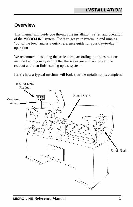
Here’s how a typical machine will look after the installation is complete:
MICRO-LINEReadout
MountingArm
X-axis Scale
Z-axis Scale
MLTmanual.QXD 2/12/02 4:10 PM Page 6

MICRO-LINE Reference Manual2
Packing List
• Readout & installation instructions• Mounting arm • MICRO-LINE scales
- Cable mounting hardware- Scale mounting hardware
• Warranty cardIf a component is missing, contact your MICRO-LINE distributor forreplacement parts.
Before you begin the installation procedure, check that you have received all of the components for your system:
Warranty RecordsFor future ordering information or warranty service, please record allreadout and scale information on the warranty card included with yourMICRO-LINE system. The scale catalog number and serial number arelocated on the scale assembly tag.
Copy the information here for your own records and then mail the warranty card as soon as possible.
Distributor: _____________________________________________
Address: _____________________________________________
Telephone: _____________________________________________
Catalog No. Serial No.Readout ________________ ___________________Axis #1 ________________ ___________________ Axis #2: ________________ ___________________Axis #3: ________________ ___________________
Date of Purchase: ____________________________________
Preparation
INSTALLATION
MLTmanual.QXD 2/12/02 4:10 PM Page 7
MICRO-LINE Reference Manual
INSTALLATION
Installing the Readout
Follow the readout installation instructions that are included with yourmounting arm bracket kit. The electrical specifications for the readoutare listed on pg. 27.
After the installation is complete, proceed to “Power Up.”
Installing the Scales
Install the linear encoders according to installation instructions foundwithin your Micro-Line system manual. These general installationinstructions are found on page 33. Read these instructions completelyeven though bracket kit instructions supersede them.
3
MLTmanual.QXD 2/12/02 4:10 PM Page 10

4 MICRO-LINE Reference Manual
INSTALLATION
Power Up
Press the switch on the back of the readout to power up the system. Aseries of tests will check that the display, keypad, and memory are allworking properly.
If a problem is detected, an error code will appear on the screen. (Errormessages and solutions are listed on pgs. 25 - 26.) It is important tonote that the E1 message will appear every time you power up yoursystem and does not indicate a problem. It merely indicates that the system had lost power. To acknowledge the message, press the CLEARkey and proceed to the DRO mode.
Note: If the E1 message appears at any other time during normal operation, refer to pg. 25 for possible problems and solutions.
When the system is not used for more than 90 minutes, a decimal pointwill “scroll” across the X-axis display, indicating that the display saverhas been activated. The display saver, like a screen saver on a computermonitor, will help prolong the life of your readout.
If the display saver has been activated, press any key on the readout ormove any axis to return to the normal DRO view.
Display Saver
MLTmanual.QXD 2/12/02 4:10 PM Page 11
5MICRO-LINE Reference Manual
SETUP
There are 3 to 4 parameters that you can define on your system:
• Display resolution (diS)• Linear error compensation (LEC)• Scale count directions (Ct dir)• Input 3 ON/OFF for international units
Establish each setting the first time you power up the system. You canchange the parameters later by returning to Setup and then using theENTER key to scroll to the appropriate category.
Anytime you change the linear error compensation, or count directionfor an axis, the absolute and incremental displays for that axis will bereset to 0. If you change these settings, you’ll need to reestablish thedatum point.
For international units using 5µm (0.0002”) scales with referencemarks, you will need to recall Datum. See page 32.
When in the SetUp mode, use the CLEAR key when you want to back-space, restore the previous value or access the previous parameter.
Parameter Setup
MLTmanual.QXD 2/12/02 4:10 PM Page 14
6 MICRO-LINE Reference Manual
SETUP
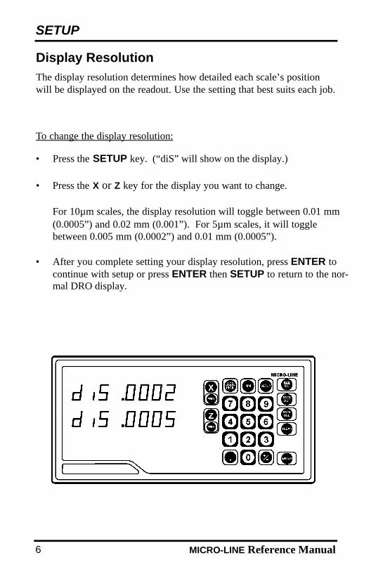
The display resolution determines how detailed each scale’s positionwill be displayed on the readout. Use the setting that best suits each job.
Display Resolution
To change the display resolution:
• Press the SETUP key. (“diS” will show on the display.)
• Press the X or Z key for the display you want to change.
For 10µm scales, the display resolution will toggle between 0.01 mm (0.0005”) and 0.02 mm (0.001”). For 5µm scales, it will toggle between 0.005 mm (0.0002”) and 0.01 mm (0.0005”).
• After you complete setting your display resolution, press ENTER to continue with setup or press ENTER then SETUP to return to the nor-mal DRO display.
MLTmanual.QXD 2/12/02 4:10 PM Page 15
MICRO-LINE Reference Manual 7
SETUP
Linear Error Compensation
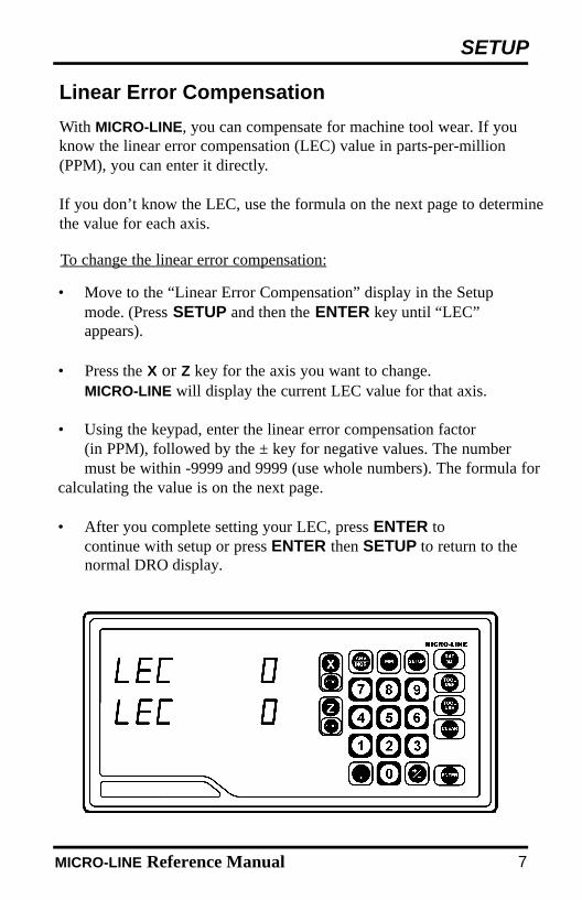
With MICRO-LINE, you can compensate for machine tool wear. If youknow the linear error compensation (LEC) value in parts-per-million(PPM), you can enter it directly.
If you don’t know the LEC, use the formula on the next page to determinethe value for each axis.
• Move to the “Linear Error Compensation” display in the Setup mode. (Press SETUP and then the ENTER key until “LEC”appears).
• Press the X or Z key for the axis you want to change. MICRO-LINE will display the current LEC value for that axis.
• Using the keypad, enter the linear error compensation factor (in PPM), followed by the ± key for negative values. The number must be within -9999 and 9999 (use whole numbers). The formula for
calculating the value is on the next page.
• After you complete setting your LEC, press ENTER to continue with setup or press ENTER then SETUP to return to the normal DRO display.
To change the linear error compensation:
MLTmanual.QXD 2/12/02 4:10 PM Page 18
8 MICRO-LINE Reference Manual
SETUP
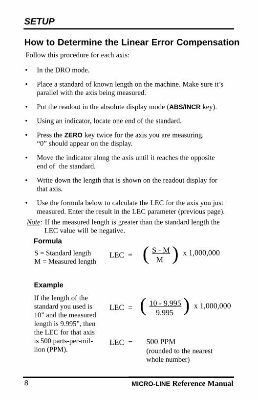
( S - MM
LEC = ) x 1,000,000S = Standard lengthM = Measured length
• In the DRO mode.
• Place a standard of known length on the machine. Make sure it’sparallel with the axis being measured.
• Put the readout in the absolute display mode (ABS/INCR key).
• Using an indicator, locate one end of the standard.
• Press the ZERO key twice for the axis you are measuring. “0” should appear on the display.
• Move the indicator along the axis until it reaches the opposite end of the standard.
• Write down the length that is shown on the readout display for that axis.
• Use the formula below to calculate the LEC for the axis you just measured. Enter the result in the LEC parameter (previous page).
How to Determine the Linear Error CompensationFollow this procedure for each axis:
Formula
Example
If the length of thestandard you used is10” and the measuredlength is 9.995”, thenthe LEC for that axisis 500 parts-per-mil-lion (PPM).
( 10 - 9.9959.995
LEC = ) x 1,000,000
LEC = 500 PPM (rounded to the nearest whole number)
Note: If the measured length is greater than the standard length the LEC value will be negative.
MLTmanual.QXD 2/12/02 4:10 PM Page 19

MICRO-LINE Reference Manual 9
SETUP
• Move to the “Count Direction” display in the Setup mode. (Press SETUP and then the ENTER key until “Ct dir” appears).
• Press the appropriate axis key (X or Z) to change the count direction.
• After you complete setting your count direction, press ENTER to con-tinue with setup or press ENTER then SETUP to return to the normal DRO display.
To change the count direction:
Count DirectionUse the count direction setting to define the positive counting directionfor each scale. The direction will be displayed as a “1” or a “2” (thenumbers are not assigned to a particular direction). You only need tochange the count direction if the scale is counting in the negative direction during a positive move, or vice versa.
Refer to Conventions (pg. 31) for more guidelines.
MLTmanual.QXD 2/12/02 4:10 PM Page 22
MICRO-LINE Reference Manual
SETUP
10
International Units Only
Input 3 ON/OFF
This parameter allows you to activate the third input. When this inputis enabled, Inputs 2 and 3 will be coupled on the Z-axis (both scaleswill count on the Z-axis).
When Input 3 is enabled, additional parameters will need to be setup.Refer to the procedures on pages 7-9 for setting up the Linear ErrorCompensation and Count Direction Setup functions.
MLTmanual.QXD 2/12/02 4:10 PM Page 23

MICRO-LINE Reference Manual
SETUP
11
Testing the Scales
Follow these steps to confirm that your scales have been installed proper-ly. This test will confirm the scale’s electrical operation, and will alsocheck the installation integrity.
• Locate a magnetic base on the machine and set the dial indicator on the scale’s reading head casting. Zero the readout and the indicator.
• Move the axis through the full travel and return the dial to “0.” The readout should also read 0 (±.0005” for 10µm scales; ±0.0002” for 5µm scales). If it doesn’t, then the scale cable may be loose, or the scale, mounting bracket, or reading head may need to be tightened or realigned.
• Repeat these steps for each scale.
MLTmanual.QXD 2/12/02 4:10 PM Page 26
12 MICRO-LINE Reference Manual
OPERATION
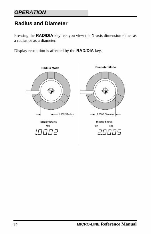
Radius and Diameter
Pressing the RAD/DIA key lets you view the X-axis dimension either asa radius or as a diameter.
Display resolution is affected by the RAD/DIA key.
MLTmanual.QXD 2/12/02 4:10 PM Page 27

13MICRO-LINE Reference Manual
OPERATION
Setting the Datum (Absolute Zero)
MICRO-LINE allows you to measure both absolute and incrementaldimensions. A dimension measured from the point you define as thedatum is an absolute dimension. A dimension measured from any otherpoint on your print is an incremental dimension.
Datum, also known as absolute zero or workpiece zero, is the referencepoint from which MICRO-LINE will base all of your part’s coordinates.When the readout is in the ABS mode, it is actually measuring the dis-tance from the datum to the machine axis’current position.
You will need to establish a datum for every job. Your datum mayalready be identified on your print; if it isn’t, then establish a datum thatallows you to measure most of your part’s dimensions directly, with theleast number of calculations.
All of the dimensions in the drawing below are based from the datum.
MLTmanual.QXD 2/12/02 4:10 PM Page 30
MICRO-LINE Reference Manual
OPERATION
14
• Using the ABS/INCR key, select the absolute (ABS) mode. Also check that the proper measurement (inch or mm) is selected.
• Using RAD/DIA key, select the Radius mode.
• Move the tool to a known point, i.e. the outside diameter of the workpiece or the face of the workpiece.
• Press the ZERO key once for the axis (X or Z) for which you’re entering a dimension.
• Using the keypad, enter the distance from your tool’s current location to the point you want to establish as the datum. Include a decimal point (.) and minus (-) sign when necessary.
• Press the ZERO key for the other axis, or press ENTER to return to the DRO display.
To set the datum using an offset:
To set the datum at the tool’s current position:
• Position the workpiece in the chuck. Move the tool until it is positioned at the location where you would like to establish thedatum.
• Using the ABS/INCR key, select the absolute (ABS) mode.
• Press the X-axis ZERO key twice to establish the current X-axis position as the datum. Repeat for the Z-axis.
If you’re using 5µm (0.0002”) scales (international units only), MICRO-LINE can recall your last datum position each time you powerup the system (refer to pg. 32 for the proper procedure).
MLTmanual.QXD 2/12/02 4:10 PM Page 31
15MICRO-LINE Reference Manual
OPERATION
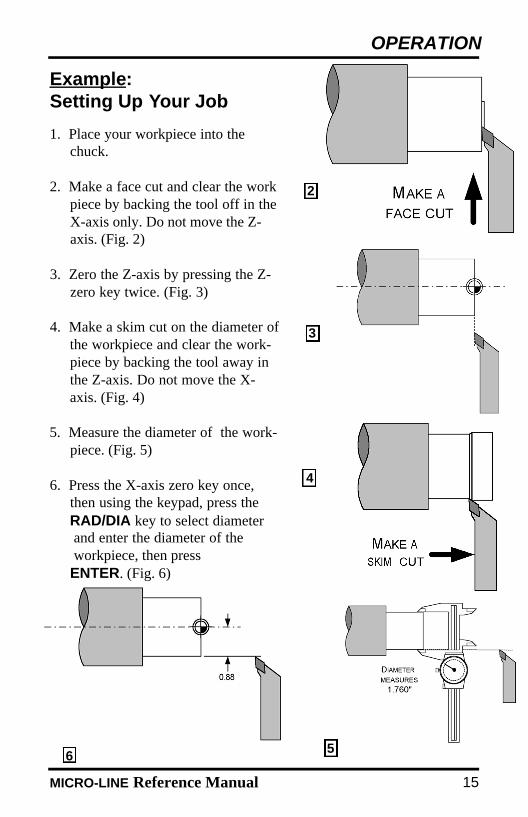
1. Place your workpiece into the chuck.
2. Make a face cut and clear the workpiece by backing the tool off in theX-axis only. Do not move the Z-axis. (Fig. 2)
3. Zero the Z-axis by pressing the Z-zero key twice. (Fig. 3)
4. Make a skim cut on the diameter ofthe workpiece and clear the work-piece by backing the tool away inthe Z-axis. Do not move the X-axis. (Fig. 4)
5. Measure the diameter of the work-piece. (Fig. 5)
6. Press the X-axis zero key once,then using the keypad, press theRAD/DIA key to select diameter and enter the diameter of the workpiece, then pressENTER. (Fig. 6)
Example:Setting Up Your Job
2
3
4
56
MLTmanual.QXD 2/12/02 4:10 PM Page 34
16 MICRO-LINE Reference Manual
OPERATION
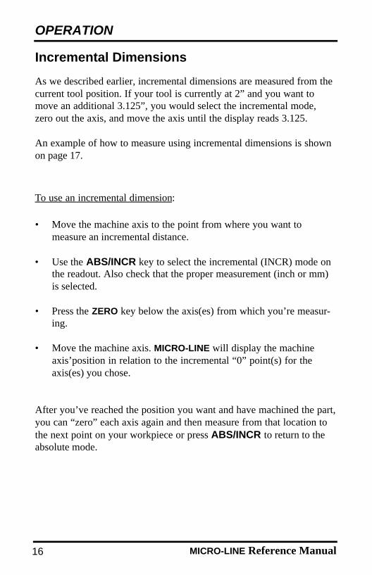
As we described earlier, incremental dimensions are measured from thecurrent tool position. If your tool is currently at 2” and you want tomove an additional 3.125”, you would select the incremental mode,zero out the axis, and move the axis until the display reads 3.125.
An example of how to measure using incremental dimensions is shownon page 17.
• Move the machine axis to the point from where you want to measure an incremental distance.
• Use the ABS/INCR key to select the incremental (INCR) mode on the readout. Also check that the proper measurement (inch or mm) is selected.
• Press the ZERO key below the axis(es) from which you’re measur-ing.
• Move the machine axis. MICRO-LINE will display the machine axis’position in relation to the incremental “0” point(s) for the axis(es) you chose.
After you’ve reached the position you want and have machined the part,you can “zero” each axis again and then measure from that location tothe next point on your workpiece or press ABS/INCR to return to theabsolute mode.
To use an incremental dimension:
Incremental Dimensions
MLTmanual.QXD 2/12/02 4:10 PM Page 35
17MICRO-LINE Reference Manual
OPERATION
Example: Incremental Dimensions
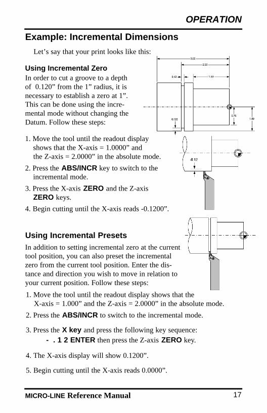
Let’s say that your print looks like this:
1. Move the tool until the readout displayshows that the X-axis = 1.0000” and the Z-axis = 2.0000” in the absolute mode.
2. Press the ABS/INCR key to switch to theincremental mode.
3. Press the X-axis ZERO and the Z-axisZERO keys.
4. Begin cutting until the X-axis reads -0.1200”.
Using Incremental ZeroIn order to cut a groove to a depthof 0.120” from the 1” radius, it isnecessary to establish a zero at 1”.This can be done using the incre-mental mode without changing theDatum. Follow these steps:
Using Incremental Presets
In addition to setting incremental zero at the currenttool position, you can also preset the incrementalzero from the current tool position. Enter the dis-tance and direction you wish to move in relation toyour current position. Follow these steps:
1. Move the tool until the readout display shows that the X-axis = 1.000” and the Z-axis = 2.0000” in the absolute mode.
2. Press the ABS/INCR to switch to the incremental mode.
3. Press the X key and press the following key sequence:- . 1 2 ENTER then press the Z-axis ZERO key.
4. The X-axis display will show 0.1200”.
5. Begin cutting until the X-axis reads 0.0000”.
MLTmanual.QXD 2/12/02 4:10 PM Page 38
MICRO-LINE Reference Manual18
OPERATION
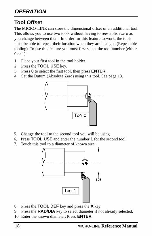
The MICRO-LINE can store the dimensional offset of an additional tool.This allows you to use two tools without having to reestablish zero asyou change between them. In order for this feature to work, the toolsmust be able to repeat their location when they are changed (Repeatabletooling). To use this feature you must first select the tool number (either0 or 1).
Tool Offset
1. Place your first tool in the tool holder.2. Press the TOOL USE key.3. Press 0 to select the first tool, then press ENTER.4. Set the Datum (Absolute Zero) using this tool. See page 13.
5. Change the tool to the second tool you will be using.6. Press TOOL USE and enter the number 1 for the second tool.7. Touch this tool to a diameter of known size.
8. Press the TOOL DEF key and press the X key.9. Press the RAD/DIA key to select diameter if not already selected.10. Enter the known diameter. Press ENTER.
MLTmanual.QXD 2/12/02 4:10 PM Page 39
MICRO-LINE Reference Manual
OPERATION
19
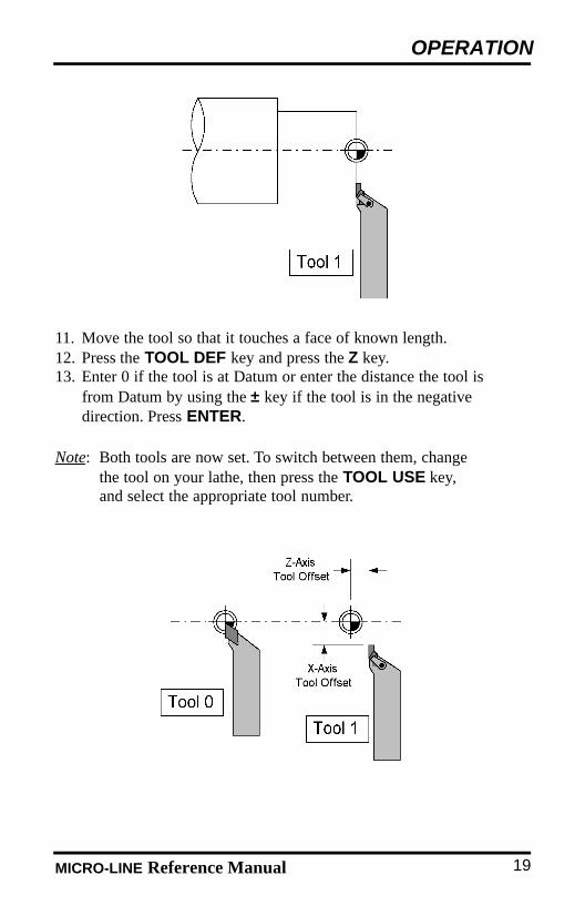
11. Move the tool so that it touches a face of known length.12. Press the TOOL DEF key and press the Z key.13. Enter 0 if the tool is at Datum or enter the distance the tool is
from Datum by using the ± key if the tool is in the negative direction. Press ENTER.
Note: Both tools are now set. To switch between them, changethe tool on your lathe, then press the TOOL USE key,and select the appropriate tool number.
MLTmanual.QXD 2/12/02 4:10 PM Page 42

20 MICRO-LINE Reference Manual
TROUBLESHOOTING
Troubleshooting IntroductionRefer to this troubleshooting guide whenever you have questions orconcerns about the operation of your MICRO-LINE system.
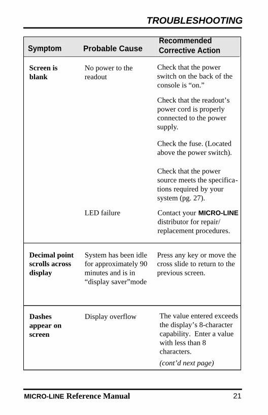
This guide is arranged in three columns entitled Symptom, ProbableCause and Recommended Corrective Action. The symptoms are listedin the order of the most common, easiest to check, and least expensiveto correct.
First locate the symptom that best describes the problem you’re tryingto solve. Then identify the probable cause that most closely matches theproblem and implement the recommended corrective action.
If a problem persists or cannot be resolved using this manual, contactyour MICRO-LINE distributor for further assistance.
MLTmanual.QXD 2/12/02 4:10 PM Page 43
MICRO-LINE Reference Manual 21
TROUBLESHOOTING
RecommendedCorrective Action
Decimal pointscrolls acrossdisplay
Press any key or move thecross slide to return to theprevious screen.
System has been idlefor approximately 90minutes and is in“display saver”mode
Symptom Probable Cause
Screen isblank
Check that the powerswitch on the back of theconsole is “on.”
No power to thereadout
Check that the readout’spower cord is properlyconnected to the powersupply.
Check that the powersource meets the specifica-tions required by your system (pg. 27).
Contact your MICRO-LINEdistributor for repair/replacement procedures.
LED failure
Dashesappear onscreen
The value entered exceedsthe display’s 8-charactercapability. Enter a value with less than 8characters.
(cont’d next page)
Display overflow
Check the fuse. (Locatedabove the power switch).
MLTmanual.QXD 2/12/02 4:10 PM Page 44
MICRO-LINE Reference Manual22
TROUBLESHOOTING
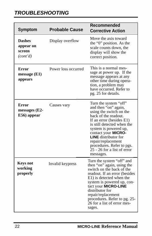
Keys notworking properly
Errormessages (E2-E56) appear
Causes vary
Invalid keypress
SymptomRecommendedCorrective ActionProbable Cause
Turn the system “off”and then “on” again,using the switch on theback of the readout.If an error (besides E1)is still detected when thesystem is powered up,contact your MICRO-LINE distributor forrepair/replacement procedures. Refer to pgs.25 - 26 for a list of errormessages.
Dashesappear onscreen(cont’d)
Move the axis towardthe “0” position. As thescale counts down, thedisplay will show thecorrect position.
Display overflow
Turn the system “off” andthen “on” again, using theswitch on the back of thereadout. If an error (besidesE1) is detected when thesystem is powered up, con-tact your MICRO-LINEdistributor forrepair/replacement procedures. Refer to pg. 25-26 for a list of error mes-sages.
Errormessage (E1)appears
Power loss occurred This is a normal mes-sage at power up. If themessage appears at anyother time during opera-tion, a problem mayhave occurred. Refer topg. 25 for details.
MLTmanual.QXD 2/12/02 4:10 PM Page 41
MICRO-LINE Reference Manual
TROUBLESHOOTING
23
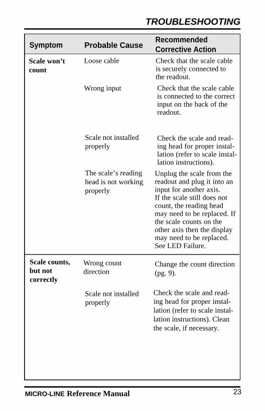
Scale counts,but not correctly
Check that the scale cableis securely connected tothe readout.
Loose cable
Check that the scale cableis connected to the correctinput on the back of thereadout.
Wrong input
Check the scale and read-ing head for proper instal-lation (refer to scale instal-lation instructions).
Scale not installedproperly
Scale won’tcount
Check the scale and read-ing head for proper instal-lation (refer to scale instal-lation instructions). Cleanthe scale, if necessary.
Scale not installedproperly
Change the count direction (pg. 9).
Wrong count direction
SymptomRecommendedCorrective ActionProbable Cause
Unplug the scale from thereadout and plug it into aninput for another axis. If the scale still does notcount, the reading headmay need to be replaced. Ifthe scale counts on theother axis then the display may need to be replaced.See LED Failure.
The scale’s readinghead is not workingproperly
MLTmanual.QXD 2/12/02 4:10 PM Page 40

MICRO-LINE Reference Manual24
TROUBLESHOOTING
Improper procedure Press the ENTER key aftereach parameter value isentered. If you pressanother key instead, thenew value may not besaved. Refer to pgs. 5-10for proper procedures.
Setup doesnot save values
Numbersdon’tappear/arefaded on thedisplay
LED failure Turn the system “off” andthen “on” again, using theswitch on the back of thereadout. If this does notcorrect the problem, contact your MICRO-LINEdistributor forrepair/replacementprocedures.
SymptomRecommendedCorrective Action
Probable Cause
MLTmanual.QXD 2/12/02 4:10 PM Page 37
MICRO-LINE Reference Manual
TROUBLESHOOTING
25
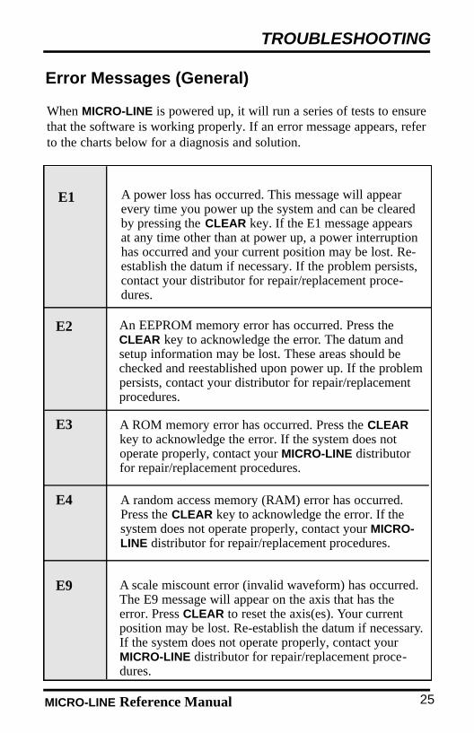
A ROM memory error has occurred. Press the CLEARkey to acknowledge the error. If the system does notoperate properly, contact your MICRO-LINE distributorfor repair/replacement procedures.
A power loss has occurred. This message will appearevery time you power up the system and can be clearedby pressing the CLEAR key. If the E1 message appearsat any time other than at power up, a power interruptionhas occurred and your current position may be lost. Re-establish the datum if necessary. If the problem persists,contact your distributor for repair/replacement proce-dures.
A random access memory (RAM) error has occurred.Press the CLEAR key to acknowledge the error. If thesystem does not operate properly, contact your MICRO-LINE distributor for repair/replacement procedures.
A scale miscount error (invalid waveform) has occurred.The E9 message will appear on the axis that has theerror. Press CLEAR to reset the axis(es). Your currentposition may be lost. Re-establish the datum if necessary.If the system does not operate properly, contact yourMICRO-LINE distributor for repair/replacement proce-dures.
Error Messages (General)
E1
E2
E3
E4
E9
When MICRO-LINE is powered up, it will run a series of tests to ensurethat the software is working properly. If an error message appears, referto the charts below for a diagnosis and solution.
An EEPROM memory error has occurred. Press theCLEAR key to acknowledge the error. The datum andsetup information may be lost. These areas should bechecked and reestablished upon power up. If the problempersists, contact your distributor for repair/replacementprocedures.
MLTmanual.QXD 2/12/02 4:10 PM Page 36
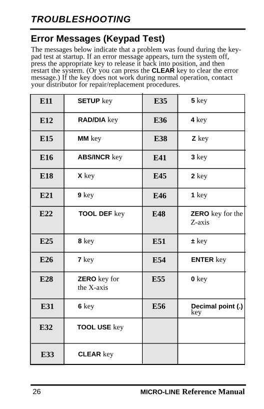
SETUP keyE11
E12
MM keyE15
E16
X keyE18
E21
TOOL DEF keyE22
E25
7 keyE26
E28
RAD/DIA key
ABS/INCR key
9 key
8 key
ZERO key forthe X-axis
E31 6 key
E35
E36
E38
E41
E45
E46
E48
E51
E54
E55
E32
E56
TOOL USE key
5 key
4 key
Z key
E33 CLEAR key
3 key
2 key
1 key
ZERO key for theZ-axis
± key
ENTER key
0 key
Decimal point (.)key
T R O U B L E S H O O T I N G
MICRO-LINE Reference Manual26
Error Messages (Keypad Test)The messages below indicate that a problem was found during the key-pad test at startup. If an error message appears, turn the system off,press the appropriate key to release it back into position, and thenrestart the system. (Or you can press the CLEAR key to clear the errormessage.) If the key does not work during normal operation, contactyour distributor for repair/replacement procedures.
MLTmanual.QXD 2/12/02 4:10 PM Page 33
MICRO-LINE Reference Manual
REFERENCE
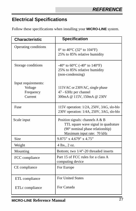
Characteristic
Operating conditions0° to 40°C (32° to 104°F)25% to 85% relative humidity
Storage conditions -40° to 60°C (-40° to 140°F)25% to 85% relative humidity (non-condensing)
115VAC or 230VAC, single phase47 - 63Hz per channel300mA @ 115V, 150mA @ 230V
Input requirements:VoltageFrequencyCurrent
Fuse 115V operation: 1/2A, 250V, 3AG, slo-blo230V operation: 1/4A, 250V, 3AG, slo-blo
Position signals: channels A & BTTL square wave signal in quadrature(90° nominal phase relationship)Maximum input rate: 70 kHz
Scale input
Part 15 of FCC rules for a class Acomputing device
Size 9.875” x 4.679” x 4.75”
Electrical Specifications
Weight 4 lbs., 2 oz.
Mounting Bottom; two 1/4”-20 threaded inserts
Follow these specifications when installing your MICRO-LINE system.
FCC compliance
CE compliance
ETL compliance
ETLc compliance
For Europe
For United States
For Canada
27
Specification
MLTmanual.QXD 2/12/02 4:10 PM Page 32

MICRO-LINE Reference Manual
REFERENCE
28
Factory Default Settings
Display Resolution
Linear ErrorCompensation
Count Direction
Tool Offset
Display Units
Display Mode
High (0.0005"/0.01 mm for 10µm scale)
(0.0002”/0.005 mm for 5µm scale)
0 parts per million
1
Tool 0 X = 0 , Z = 0
Inches
ABS (absolute dimensions)
Radius/Diameter Radius
Tool 1 X = 0 , Z = 0
MLTmanual.QXD 2/12/02 4:10 PM Page 29
MICRO-LINE Reference Manual
REFERENCE
29
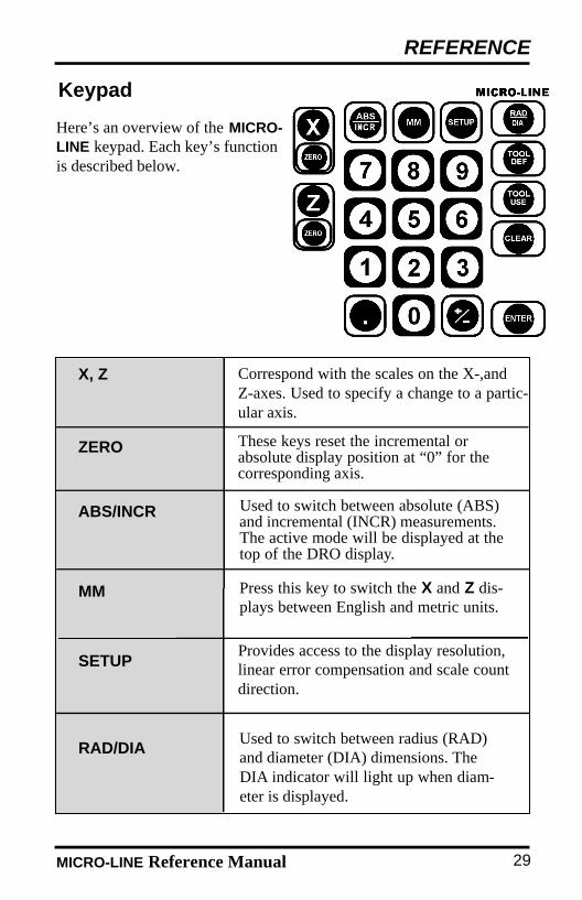
Keypad
Here’s an overview of the MICRO-LINE keypad. Each key’s functionis described below.
ABS/INCR Used to switch between absolute (ABS)and incremental (INCR) measurements.The active mode will be displayed at thetop of the DRO display.
RAD/DIAUsed to switch between radius (RAD)and diameter (DIA) dimensions. TheDIA indicator will light up when diam-eter is displayed.
MM Press this key to switch the X and Z dis-plays between English and metric units.
X, Z
ZERO
Correspond with the scales on the X-,and Z-axes. Used to specify a change to a partic-ular axis.
These keys reset the incremental orabsolute display position at “0” for thecorresponding axis.
SETUPProvides access to the display resolution,linear error compensation and scale countdirection.
MLTmanual.QXD 2/12/02 4:10 PM Page 28
MICRO-LINE Reference Manual
REFERENCE
30
±Changes the sign of the entered value from positive (+) to negative (-) or vice versa.Numbers are positive unless a (-) appears infront of them.
TOOL DEF
TOOL USE
CLEAR
Used to establish tool offset.
To establish which tool offset will be used.
Acts as backspace key during numericentry; otherwise, it clears or cancels the lastoperation.
ENTER Completes numeric operations; selects nextparameter in SETUP.
. Decimal point can be used during numericentry; also used to access the recall featurefor international units with 5µm (0.0002”)scales after power up.
0-9 Used to enter a distance.
MLTmanual.QXD 2/12/02 4:10 PM Page 25

MICRO-LINE Reference Manual
REFERENCE
31
The MICRO-LINE system is considered to be in the DRO (digital read-out) mode when the X-axis and Z-axis positions are displayed.
DRO Mode
MICRO-LINE uses positive and negative numbers to display the positionof the tool along each axis. The graphic below shows a typical setup forthe positive and negative count directions for the X-and Z-axes on alathe. All of the examples in this manual are based upon this setup.
X-axis: The axis will move away from the center for a positive count direction.
Z-axis: The axis will move away from thespindle for a positive count direction.
Count Direction
Conventions
This section identifies the standard conventions that apply to yourMICRO-LINE system.
MLTmanual.QXD 2/12/02 4:10 PM Page 24

MICRO-LINE Reference Manual
REFERENCE
32
Recalling the Last Datum Setting ForInternational Units
If you’re using 5µm MICRO-LINE scales, MICRO-LINE can retrieveyour last datum setting when you power up your system. This feature isespecially useful when you have to shut down the system in the middleof a job, or if a power interruption occurs. When power is restored,MICRO-LINE will use Position-TracTM technology to read the scales’reference marks and recall the datum within seconds.
The recall feature only works after you have completed the initial system setup and established a datum, so it won’t be accessible the very first time you turn on the readout. After you’ve completed thoseoperations, you can recall the datum for every power up thereafter.
To recall your last datum:
• Power up the system.
• Press the CLEAR key to clear the E1 message.
• Press the decimal point (.) on the readout’s keypad. Move the tool in the positive count direction along the X-axis. Keep moving it until the system recalls the datum and “found” flashes on the screen. The system will automatically reset the X-axis value to reflect the distance from the tool’s current position to the datum.
Repeat this procedure for the Z-axis, always moving the tool in the positive count direction.
After you’ve completed the recall procedure, you can move to the datum bypositioning the tool until the display reads “0” for each axis.
Note: If Input 3 is being used, the datum will not be correct until both the Z-axisand Input 3 scales have been recalled.
MLTmanual.QXD 2/12/02 4:10 PM Page 21

MICRO-LINE Reference Manual
REFERENCE
• Installation brackets and tools are available.• Your Authorized ACU-RITE Distributor can assist you
in selecting brackets and tools for your installation.
Please do not expose the scale to the following:
General Installation Instructions for the Scale
Installation Brackets
33
MLTmanual.QXD 2/12/02 4:10 PM Page 20
MICRO-LINE Reference Manual34
REFERENCE
IntroductionThe Micro-Line precision glass scale provides the accuracy and reliabili-ty of an ACU-RITE measuring system. Features and options include:
• Digital resolutions of 5 or 10µm.• Accuracy Grade of ± 10 µm/1000mm.• Home reference signals on international units only.• Braided cables of 10 or 15ft. lengths.• Two scale case forms:
• Top mounting scale available 2 - 120” measuring length• End mounting scale available 2 - 22” measuring length
• Mounting Fasteners• Installation Brackets
See Page 2 to fill out warranty record information.
Scale mounting hardware and cable mounting hardware areprovided with each Micro-Line Scale.
MLTmanual.QXD 2/12/02 4:10 PM Page 17
MICRO-LINE Reference Manual 35
REFERENCE
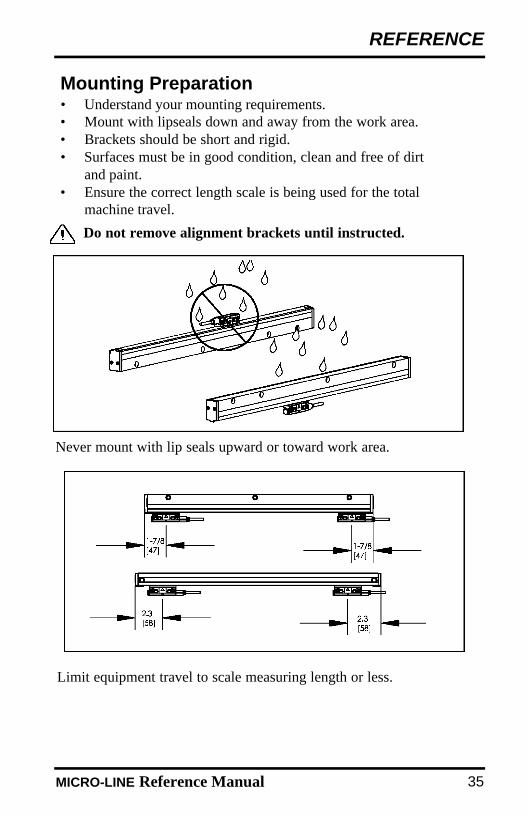
• Understand your mounting requirements.• Mount with lipseals down and away from the work area.• Brackets should be short and rigid.• Surfaces must be in good condition, clean and free of dirt
and paint.• Ensure the correct length scale is being used for the total
machine travel.
Do not remove alignment brackets until instructed.
Never mount with lip seals upward or toward work area.
Mounting Preparation
Limit equipment travel to scale measuring length or less.
MLTmanual.QXD 2/12/02 4:10 PM Page 16
36 MICRO-LINE Reference Manual
REFERENCE
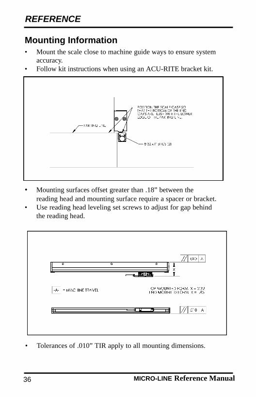
• Tolerances of .010” TIR apply to all mounting dimensions.
• Mount the scale close to machine guide ways to ensure system accuracy.
• Follow kit instructions when using an ACU-RITE bracket kit.
Mounting Information
• Mounting surfaces offset greater than .18” between the reading head and mounting surface require a spacer or bracket.
• Use reading head leveling set screws to adjust for gap behindthe reading head.
MLTmanual.QXD 2/12/02 4:10 PM Page 13
MICRO-LINE Reference Manual 37
REFERENCE
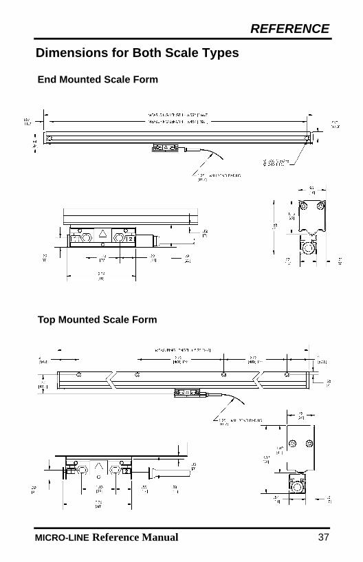
Dimensions for Both Scale Types
End Mounted Scale Form
Top Mounted Scale Form
MLTmanual.QXD 2/12/02 4:10 PM Page 12
MICRO-LINE Reference Manual38
REFERENCE
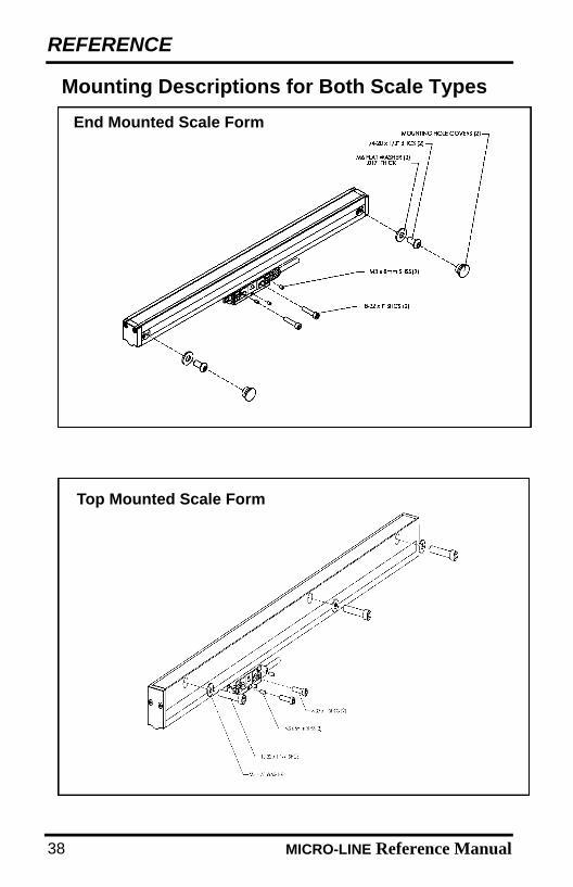
Mounting Descriptions for Both Scale Types
End Mounted Scale Form
Top Mounted Scale Form
MLTmanual.QXD 2/12/02 4:10 PM Page 9

MICRO-LINE Reference Manual 39
Installation Procedure
These steps apply to all mounting conditions. Although this maynot pictorially represent your application, your installation proce-dure should follow these steps.
ACU-RITE bracket kit instructions supercede this section.
• Adjust drill depths and fastener lengths as required.• Contact your authorized ACU-RITE distributor if assistance is
required.
First Steps:
1. Move the machine axis to its center of travel.2. Mark the machine axis location so that it can be recentered
easily.3. Slide the reading head with the alignment brackets attached,
along the scale case to the center of the scale case.
4. Locate the bottom of the end cap flush with the axis parting line.5. Mark one end mounting hole.6. Drill and tap the first end mounting hole. Drill and tap a
10-32 x 1/2” deep hole for a top mounting form or a 1/4-20 x 1/2” deep hole for an end mounting form. Attach the scale.
REFERENCE
MLTmanual.QXD 2/12/02 4:10 PM Page 8
40 MICRO-LINE Reference Manual
REFERENCE
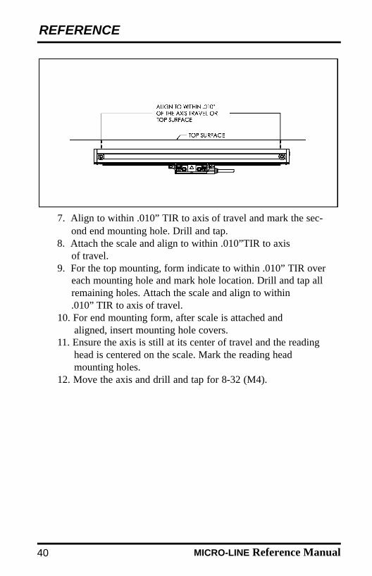
7. Align to within .010” TIR to axis of travel and mark the sec-ond end mounting hole. Drill and tap.
8. Attach the scale and align to within .010”TIR to axis of travel.
9. For the top mounting, form indicate to within .010” TIR over each mounting hole and mark hole location. Drill and tap all remaining holes. Attach the scale and align to within .010” TIR to axis of travel.
10. For end mounting form, after scale is attached and aligned, insert mounting hole covers.
11. Ensure the axis is still at its center of travel and the reading head is centered on the scale. Mark the reading head mounting holes.
12. Move the axis and drill and tap for 8-32 (M4).
MLTmanual.QXD 2/12/02 4:10 PM Page 5
MICRO-LINE Reference Manual
REFERENCE
41
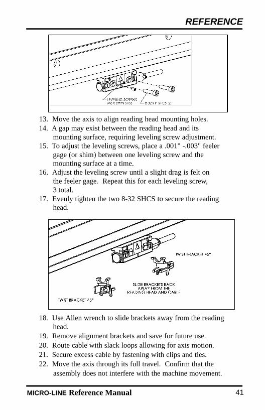
13. Move the axis to align reading head mounting holes. 14. A gap may exist between the reading head and its
mounting surface, requiring leveling screw adjustment.15. To adjust the leveling screws, place a .001" -.003" feeler
gage (or shim) between one leveling screw and themounting surface at a time.
16. Adjust the leveling screw until a slight drag is felt on the feeler gage. Repeat this for each leveling screw,3 total.
17. Evenly tighten the two 8-32 SHCS to secure the reading head.
18. Use Allen wrench to slide brackets away from the reading head.
19. Remove alignment brackets and save for future use.20. Route cable with slack loops allowing for axis motion.21. Secure excess cable by fastening with clips and ties.22. Move the axis through its full travel. Confirm that the
assembly does not interfere with the machine movement.
MLTmanual.QXD 2/12/02 4:10 PM Page 4
ACU-RITE readouts and precision glass scales are warranted to theend user against defects in material and workmanship and against anydamage that occurs to the product within three (3) years from the origi-nal purchase date. ACU-RITE will, at its discretion and expense, repairor replace the returned item or any of the item's component(s) as longas ACU-RITE receives notice of the defect or damage within the three(3) year warranty period.
The foregoing warranty obligations are in lieu of all expressedand/or implied warranties of fitness or merchantability or otherwise,and state ACU-RITE's entire liability and the end user's exclusive remedy, under any circumstance, for any claim of damage.
In no event shall ACU-RITE be liable for incidental or consequen-tial damages nor shall ACU-RITE's liability for any claims or damagearising out of or connected with this warranty or the manufacture, sale,delivery, or use of the products with which this warranty is concernedexceed the purchase price of said products.
Hassle-Free Warranty
MICRO-LINE Reference Manual42
REFERENCE
MLTmanual.QXD 2/12/02 4:10 PM Page 1

ACU-RITE INCORPORATEDOne Precision Way • Jamestown,NY 14701
MICRO-LINEFor Milling Applications
REFERENCE MANUAL
Readout SystemsPrecision Glass Scales
l l l l l l l l l l l l l l l l l
™