l jetronic
TRANSCRIPT

Electronic Gasoline Injection system
L Jetronic
© Dr. Amr Ibrahim, 2010, all rights reserved. The commercial use of these slides withoutpermission is strictly prohibited.

Principle of electronic injection systems:The electronic injection systems control the amount of injected fuel electronically
Electronic injection system consists mainly of:
• Sensors
• Electronic Control Unit (ECU)
• Actuators (e.g. solenoid operated fuel injection valves)
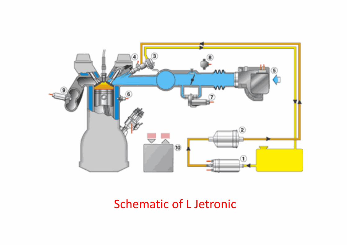
Schematic of L Jetronic
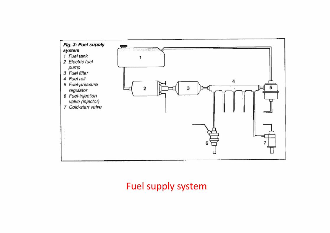
Fuel supply system
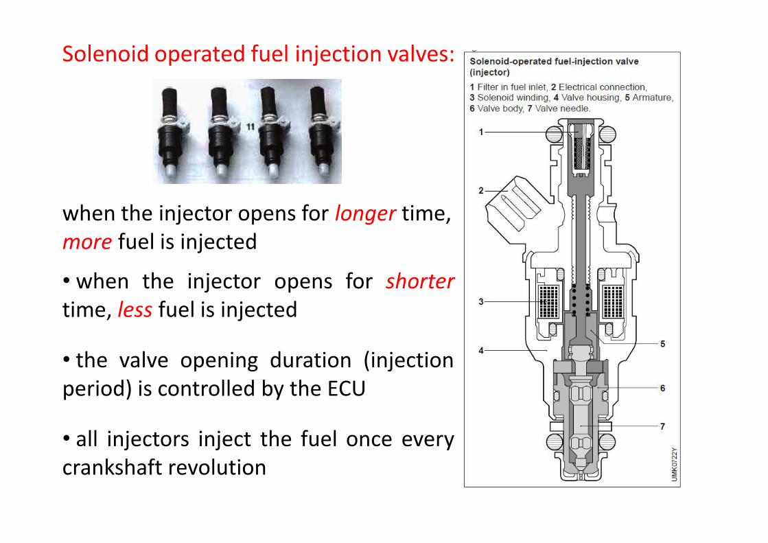
Solenoid operated fuel injection valves:
when the injector opens for longer time, more fuel is injected
• when the injector opens for shortertime, less fuel is injected
• the valve opening duration (injectionperiod) is controlled by the ECU
• all injectors inject the fuel once everycrankshaft revolution
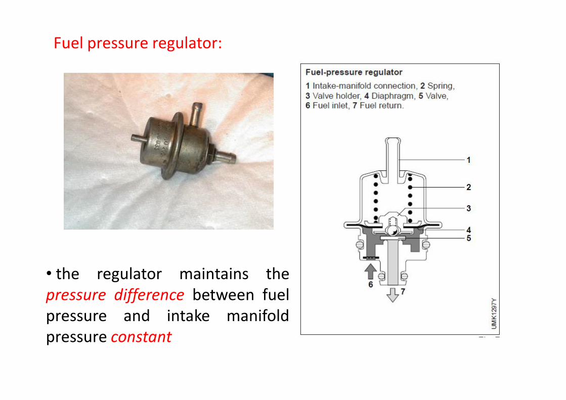
Fuel pressure regulator:
• the regulator maintains thepressure difference between fuelpressure and intake manifoldpressure constant

Electronic control unit:
• the ECU, which consists of electronic components, receives electricsignals from all engine sensors in order to determine the fuelinjection duration

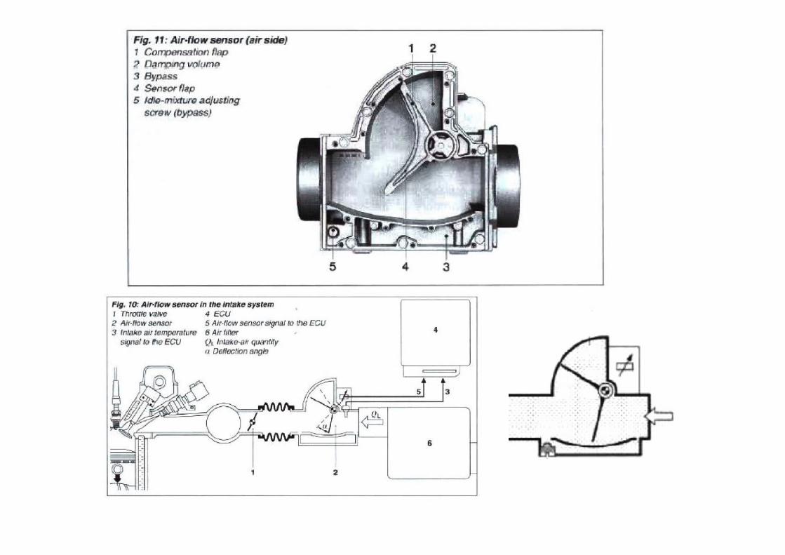
Air flow sensor:
• the air flow sensor reports the amount of engine air flow to the ECU
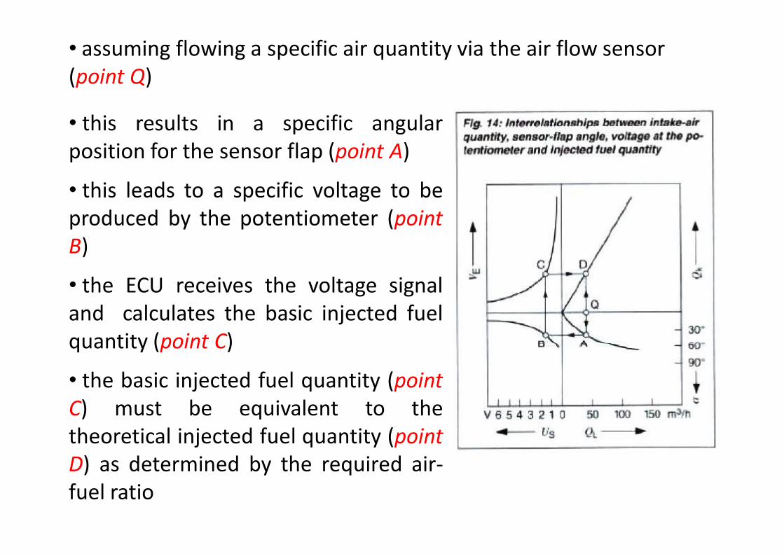
• this results in a specific angularposition for the sensor flap (point A)
• this leads to a specific voltage to beproduced by the potentiometer (pointB)
• the ECU receives the voltage signaland calculates the basic injected fuelquantity (point C)
• the basic injected fuel quantity (pointC) must be equivalent to thetheoretical injected fuel quantity (pointD) as determined by the required air-fuel ratio
• assuming flowing a specific air quantity via the air flow sensor (point Q)
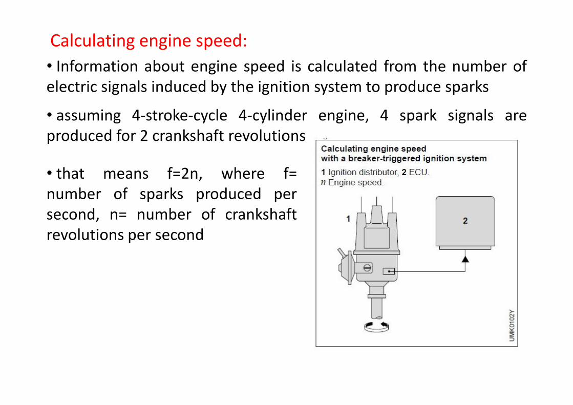
• Information about engine speed is calculated from the number ofelectric signals induced by the ignition system to produce sparks
• assuming 4-stroke-cycle 4-cylinder engine, 4 spark signals areproduced for 2 crankshaft revolutions
Calculating engine speed:
• that means f=2n, where f=number of sparks produced persecond, n= number of crankshaftrevolutions per second

Basic injection fuel quantity:
• Both the air flow and engine speed signals are the mainvariables to determine the basic fuel quantity injected for eachcrankshaft revolution. For a 4 stroke cycle engine:
)(cycle/min N/2(kg/min) m(kg/cycle)m a
a
AF (kg/cycle)m(kg/cycle)m af
• the basic injection duration, Tp, is proportional to the basic amountof injected fuel calculated from the main variables
2(rev/min) N)(cycle/min cycles amic thermodynof no
2/ (kg/cycle)m(kg/rev)m finj f,

Total injection duration:
• Tm = the pulse duration extension as determined according toengine operating conditions such as:
o engine cold start
o engine warm up
o engine load condition (idling or full load)
• Tm is a measure of fuel enrichment
• The total injection duration (the duration of electric currentflow in the injector solenoid winding) determined by the ECU, Ti,is calculated as follows:
Ti = Tp + Tm + Tu
• Tu= the pulse duration extension according to engine batteryvoltage
• the pick up time of fuel injection valves depends very much onthe battery voltage
• the lower the battery voltage, the longer the time which isneeded to build the magnetic field to open the injector
• without voltage compensation, low battery voltage would resultin the injector opening duration to be too short
• the battery voltage is fed to the ECU in order for the Tu to becalculated
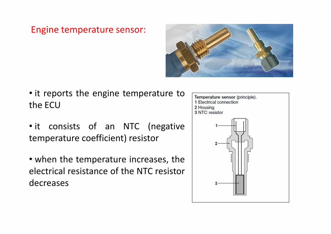
Engine temperature sensor:
• it reports the engine temperature tothe ECU
• it consists of an NTC (negativetemperature coefficient) resistor
• when the temperature increases, theelectrical resistance of the NTC resistordecreases

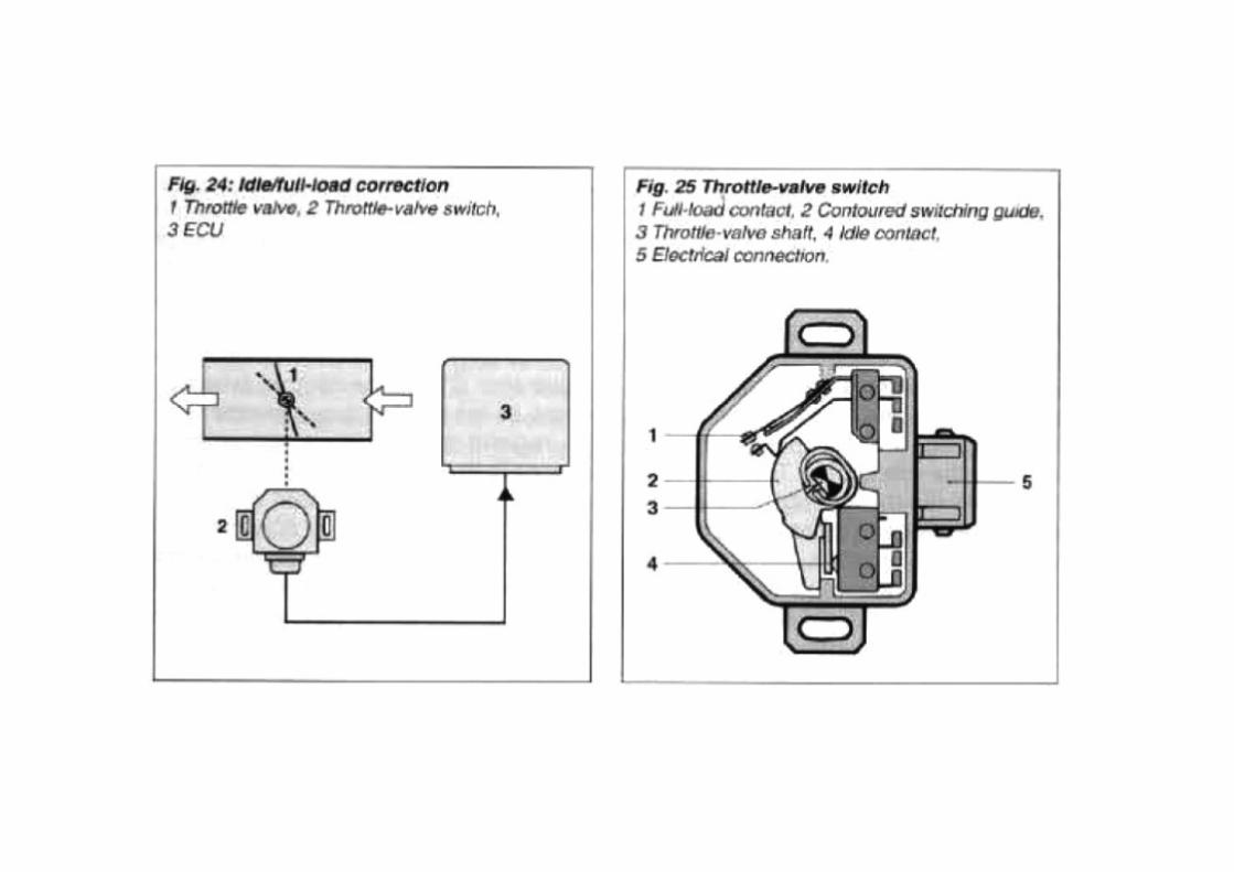
Throttle valve switch:
• it is mounted on thethrottle body and connectedto the throttle valve shaft
• it reports to the ECU whether the throttle valve is closed (idling)or fully open (full load)
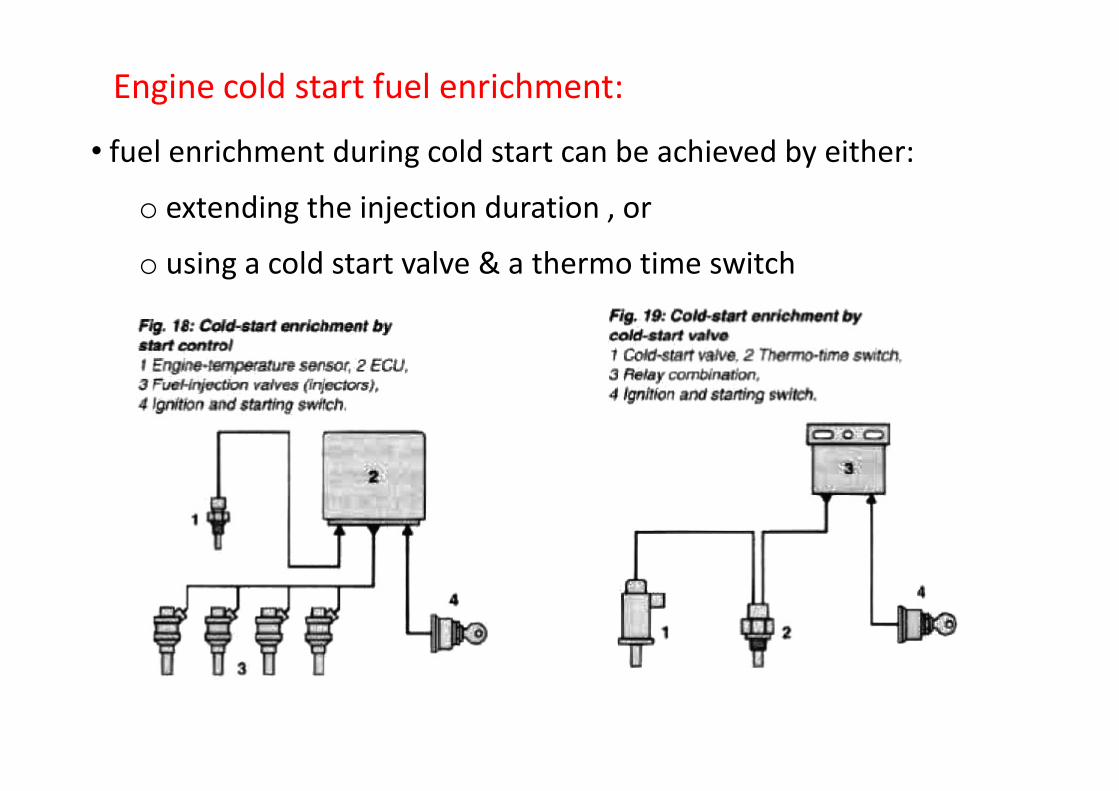
Engine cold start fuel enrichment:
• fuel enrichment during cold start can be achieved by either:
o extending the injection duration , or
o using a cold start valve & a thermo time switch

warm up fuel enrichment:
• fuel enrichment is needed duringengine warm up to compensate for fuelcondensation
• the amount of fuel enrichment dependson the engine initial temperature
Atmospherictemp=22o C

Auxiliary air device:
• it is used to increase the amount of air fuel mixture during idling when the engine is cold to overcome engine friction


Engines fitted with a 3-way catalyst:
• the engine must operate at almost stoichiometric mixture in orderfor the catalyst to operate efficiently
• lambda sensor is used in order to measure the oxygenconcentration in the exhaust gas
• the value of λ is fed to the ECU
• the ECU controls the fuel injection duration in order to keep λ=1

Lambda sensor:
Overrun fuel cutoff:• the ECU cuts off fuel injection when the throttle valve is closedwhile the engine speed is higher than the idling speed duringbraking or downhill driving
• the fuel injection starts again when engine speed reaches to theidling speed value
• this reduces engine fuel consumption and emissions
Supplementary functions
Maximum engine speed limitation:• the ECU cuts off fuel injection when engine speed increases abovethe maximum speed limit specified by the manufacturer
• fuel injection starts again when engine speed is reduced below themaximum limit