l daten technik ( ldt operation instruction turntable
TRANSCRIPT

Littfinski DatenTechnik (LDT) Bühler electronic GmbH • Ulmenstraße 43 • 15370 Fredersdorf / Germany • Tel.: +49 (0) 33439 / 867-0
Multi-Digital
Operation Instruction
TurnTable-Decoder
TT-DEC-R
from the Digital-Professional-Series !
TT-DEC-R-G Part-No.: 010513
>> finished module in a case <<
C:
IC3
Speed
P1
IC4
S1
Littfinski DatenTechnik (LDT)
K J +red brown
ST4
+ +green yellow red
16...18V~ Rückmeldg.Feedback
M1M2K Jred brown
Commands Track
KL3KL2KL1
TT-DEC-RRev. 1.2
JP1
LED1 LED2 LED3
A
KL4
7805 LM317Drehscheiben-Decoder
22...24V=
+ ~ - ~
2L 3L
(DCC und Märklin-Motorola)
Für Roco H0 Drehscheibe 42615.
Drehscheiben-DecoderTT-DEC-R
Digital-Profi werden!
Littfinski DatenTechnik (LDT)www.ldt-infocenter.com
Multi-Digital
Suitable for the Roco H0 Turntable 42615. The turntable can be equipped with 4 to 40 track connections. Not aligned opposite track connection can be adjusted by a minimum offset angle of 4.5 degree. Suitable for the data formats of Märklin Motorola and DCC. Compatible commands for the Märklin turntable electronic 7686. Therefore particular simple control via every digital command station and via any model railway software which supports the Märklin turntable electronic 7686 and with a graphic turntable imaging.
This product is not a toy! Not suitable for children under 14 years of age! The kit contains small parts, which should be kept away from children under 3! Improper use will imply danger of injuring due to sharp edges and tips! Please store this instruction carefully.

TT-DEC-R – Manual
- 1 -
Index: Page
1. Preface / Safety Instruction 2
2. Selecting the available turntable (old or new version) 2
3. Alterations on the Roco turntable 3
3.1. Free-wheeling diode soldering 3
3.2. Motor cable soldering 5
3.3. Bridge track contact isolation 7
4. Correct position of the turntable sliding switches and the setting or removing of the matching jumper JP1 of the TT-DEC-R 8
5. TT-DEC-R connection to the digital layout and to the turntable 8
5.1. TT-DEC-R connection to the digital layout 8
5.2. TT-DEC-R connection to the turntable 10
5.2.1. TT-DEC-R connection to old version 10
5.2.2. TT-DEC-R connection to new version 11
6. Turntable-Decoder TT-DEC-R programming 12
6.1. Basic address and data format programming 12
6.2. Turning direction testing 13
6.3. Track connection programming 13
6.4. Bridge track polar reversal (only 2-conductor mode) 16
6.5. Turning speed adjustment 18
6.6. Reference track synchronizing 19
6.7. Special function: Turntable test / Factory setting 19
6.8. Programming- and Control-Table 20
7. Feedback reports 21
8. Assembly plan 23

TT-DEC-R – Manual
- 2 -
1. Preface / Safety Instruction:
You have purchased the TurnTable-Decoder TT-DEC-R for your model railway layout supplied within the assortment of Littfinski DatenTechnik (LDT).
We are wishing you having a good time for the application of this product!
The purchased unit comes with 24 month guarantee (validity for the finished module and finished module in a case only).
• Please read this instruction careful. For damages caused by disregarding this instruction the right of claiming guarantee will expire. No liability will be taken over for resultant damages. You can download this manual as a PDF-file with colored pictures from the area “Downloads” at our Web-Site. The file can be opened with the Acrobat Reader. Many illustrations at this manual are identified with a file name (e.g. page_1165). You can find those files on our Web-Site at the section “Sample Connections” of the Turntable-Decoder TT-DEC-R. You can download the files as PDF-File and make a colored print at the DIN A4 format.
• Attention: Carry out any connections only with disconnected model railway layout (switch-off the transformers or disconnect the main plug).
2. Selecting the available turntable (old or new version):
The Roco H0 Turntable 42615 is available within two different versions. The difference between the two versions is the supplied 8-poles flat ribbon cable and the supplied pc-board for the under-floor drive of the turntable. For identification which version you own please have a look at the bottom of the turntable. If there is a bore at the protection cover as per the right sketch it will be the new version. Without a bore at the protection cover it will be the old version as shown to the left.
Roco Drehscheibe 42615 alte VarianteRoco Turntable 42615 old version
R OC O
0 1
schwarzblack
page_1165
R OC O
0 1
Bohrung für zusätzliche Schraubverbindungbore for additional screwed connection
Roco Drehscheibe 42615 neue VarianteRoco Turntable 42615 new version
schwarzblack
page_1165

TT-DEC-R – Manual
- 3 -
3. Alterations on the Roco Turntable:
• Important Information: Any alteration on the Roco Turntable 42615 have to be completed before the Turntable-Decoder TT-DEC-R gets into first operation. An operation of the Turntable-Decoder TT-DEC-R before the electrical changes have been completed (soldering the free-wheel diode and the drive-motor cables) can eventually damage the Turntable-Decoder TT-DEC-R and as well your turntable. After completing the electrical alterations the Roco Turntable 42615 can not be controlled anymore by the Roco-Turntable remote control unit.
3.1. Free-wheeling diode soldering:
The free-wheeling diode 1N4003 which is attached to each supplied Turntable-Decoder TT-DEC-R has to be soldered onto the pc-board of the under-floor drive to prevent the interference of the switching voltage of the interlock coil.
For this procedure please take off the protection cover of the under-floor drive mechanic as described at the Roco Manual for the turntable and read the section “Maintenance of the drive”.
After removing the protection cover you can see the pc-board and the under-floor drive of the old version shown at the left draft and the new version at the right.
Roco Drehscheibe 42615 alte VarianteRoco Turntable 42615 old version
0 L
42615-a11
schwarzblack
schwarzblack
0 142615-A11
Roco Drehscheibe 42615 neue VarianteRoco Turntable 42615 new version
The detailed images on the next page show the wiring of the under-floor drive to the pc-board before the alteration. The old version is shown at the left and the new version at the right.

TT-DEC-R – Manual
- 4 -
Roco Drehscheibe 42615 alte VarianteRoco Turntable 42615 old version
42615-a11
Roco Drehscheibe 42615 neue VarianteRoco Turntable 42615 new version
15-A11
Please solder the diode 1N4003 onto the soldering terminals of the pc-board as shown at the two detailed images.
Before soldering please shorten the connection wires of the diode 1N4003 to a length of about 1 cm and bend both wires careful at 90 degree just after the diode body. The diode 1N4003 has on one connection wire a printed ring (called cathode ring) for the correct assembly direction.
The diode 1N4003 has been correct soldered at the old version if the cathode ring shows to the right respectively direct to the track connections (image left).
At the new turntable version is the soldered position of the diode 1N4003 correct if the cathode ring shows to the bottom to the worm drive (image right).
Roco Drehscheibe 42615 alte VarianteRoco Turntable 42615 old version
42615-a11
Diode1N4003
Roco Drehscheibe 42615 neue VarianteRoco Turntable 42615 new version
15-A11
Diode1N4003

TT-DEC-R – Manual
- 5 -
3.2. Motor cable soldering:
Each Turntable-Decoder TT-DEC-R will be supplied together with a 2m 2-poles motor connection cable. On one side is the cable is equipped with two inductors.
Originally is the motor of the under-floor drive connected to the pc-board via two wires. Remove this two cables by unsolder them from the motor connection and from the pc-board.
After unsoldering the two wires you should solder the motor-cable (attached to each turntable-Decoder TT-DEC-R) onto both motor connections as described within section 3.2.1. If the motor is not connected by two cables to the printed circuit board you own one of the oldest Roco version of the HO Turntable 42615. On this oldest version the motor receives the power supply via two contact springs which are riveted onto the pc-board and give contact by pressure against two contact plates at the motor. The left picture shows the motor-connection of the oldest version before alteration.
Motoranschluss vor Umbaumotor connection before rebuilding
Erster Umbauschrittfirst step of rebuilding
At the first step of alteration shown within picture right the two spring-contacts shall be bent down to the PC-board. Now there is no electrical contact to the two contacts at the motor.
At the second alteration step shown on the next page the motor cable (attached to each Turntable-Decoder TT-DEC-R) shall be soldered onto the motor. Each connection wire of one choke shall be soldered onto one of the two hexagonal contact plates of the motor. Which of the two chokes soldered to one of the two contact plates does no matter.

TT-DEC-R – Manual
- 6 -
To prevent an electrical contact to the PC-board by vibration of the motor please stick an isolation tape around the motor and over the two contact plates. The isolation tape should be long enough to isolate the contact plates as well under the pc-board.
Zweiter Umbauschrittsecond step of rebuilding
Motorkabelmotor cable
DrosselnInductors
Motoranschluss nach Umbaumotor connection after rebuilding
Motorkabelmotor cable
DrosselnInductors
IsolierbandInsulating tape
After completion of alteration of the oldest Roco HO Turntable 42615 version tighten the safety cover of the turntable as described within section 3.2.2. 3.2.1. Now solder the new motor cable to the two motor connections. Each connection wire of the inductors has to be soldered to one of the two motor connections of the under-floor drive.
Which of the two inductors soldered to which of the two motor connections does no matter.
Roco Drehscheibe 42615 alte VarianteRoco Turntable 42615 old version
Diode1N4003
Motorkabelmotor cable
DrosselnInductors
42615-a11
Roco Drehscheibe 42615 neue VarianteRoco Turntable 42615 new version
15-A11
Diode1N4003
DrosselnInductors
Motorkabelmotor cable

TT-DEC-R – Manual
- 7 -
3.2.2. Before replacing the protection cover of the turntable as described within the Roco Manual for the turntable within the section “Maintenance of the drive” and after completion of the alteration you have to feed the motor cable through the opening on the protection cover near the motor connections. Each Turntable-Decoder TT-DEC-R will be supplied together with a cable fastener for strain relief and for securing the motor cable onto the lower latch of the cover opening. The pictures on the following page show both turntable versions after attaching the protection cover including the motor cable after the completion of the electrical alteration.
Roco Drehscheibe 42615 alte VarianteRoco Turntable 42615 old version
R OC O
0 1
schwarzblack
Motorkabelmotor cable
R OC O
0 1
schwarzblack
Roco Drehscheibe 42615 neue VarianteRoco Turntable 42615 new version
Motorkabelmotor cable
3.3. Bridge track contact isolation: At the supply status the Roco turntable 42615 contains on each bridge track end two slide contacts for the connection to the selected track.
These slide contacts have to be removed or isolated before the turntable Decode TT-DEC-R will be set into function.
For removing or isolating the four sliding contacts you should remove several access tracks respectively blind tracks as described at the manual for the Roco Turntable 42615.
If you do not want to remove the four sliding contacts with a small side cutter you will have the possibility to lower the contacts to assure that no electrical contact to the track connections is possible. For this action please bend the sliding contacts carefully down and slide a little piece of cable insulation between the sliding contact and the bridge track. The sliding contact will be permanently lowered and can not provide any electrical contact to the rails of the access tracks.

TT-DEC-R – Manual
- 8 -
4. Correct position of the turntable sliding switches and the setting or removing of the matching jumper JP1 of the TT-DEC-R:
There are two sliding switches at the lower side of the turntable.
One of the two sliding switches is market with a “0” and “1”. For the operation in connection to the Turntable-Decoder TT-DEC-R this switch has always to be set onto position “1”.
The second slide switch is marked with the symbol “=” and “~”. The marking “=” indicates the setting for the operation with the 2-conductor bridge track system and the marking “~” indicates the setting for the 3-conductor system. Now select the correct switch position in accordance to the used track conductor system. Additional information can be found within the Roco Manual for the turntable at the section “Selecting the driving current system”. If you use the turntable at the 2-conductor system (sliding switch at the turntable in position “=”) please remove the jumper JP1 at the TT-DEC-R. You can find this jumper at the right between the case cover and the heat sink of the Turntable-Decoder TT-DEC-R. If the operation of the turntable is used in a 3-conductor system (sliding switch of the turntable in position “~” the jumper JP1 of the Turntable-Decoder TT-DEC-R shall remain in position (supplied position). 5. TT-DEC-R connection to the digital layout and to the turntable:
• Important Information: Switch-off the electrical supply before performing any connection work (switch-off all transformers or unplug the main connection).
5.1. TT-DEC-R connection to the digital layout: The TurnTable-Decoder TT-DEC-R receives the power supply via the two clamps at the very left side of the 6-poles connection clamp. The voltage can be between 16 and 18 Volt~ (alternated voltage of a model railway transformer). Both clamps are marked accordingly. Alternatively, the TurnTable-Decoder can be used with a supply of DC voltage of 22…24V= in any polarity. The decoder receives the digital information via the third and fourth clamp (counted from the left side) of the 6-poles connection clamp which is marked with “Commands” on the pc-board. Supply the digital information directly from the control-unit or from a booster respectively from the digital ring conductor “switching” which has been connected to all accessory decoders. To assure that the TT-DEC-R receives interference-free data do not take the digital information directly from the rails. One of the two digital clamps has been marked with red and K and the other has been marked with brown and J. The colors red and brown respectively the marking J and K will be used by most command stations.

TT-DEC-R – Manual
- 9 -
Von Digitalzentrale oder BoosterFrom command stationor booster
braunbrown
Vom ModellbahntrafoFrom transformer
gelbyellow
Ringleitung "Fahren"Ring conductor "driving"
Ringleitung "Schalten"Ring conductor "switching" braun
brown
rotred
rotred
braunbrown
Z805 LM317IC3
Speed
P1
IC4
S1
Littfinski DatenTechnik (LDT)
K J
LED1
+red brown
ST4
+ +LED2 LED3
green yellow red
ARückmeldg.Feedback
M1M2K Jred brown
Commands Track
KL3 KL4KL2KL1
TT-DEC-RRev. 1.2
JP1
Drehscheiben-Decoder
16...18V~22...24V=
+ ~ - ~
2L 3L
(DCC und Märklin-Motorola)
Für Roco H0 Drehscheibe 42615.
Drehscheiben-DecoderTT-DEC-R
Digital-Profi werden!
Littfinski DatenTechnik (LDT)www.ldt-infocenter.com
Multi-Digital
The digital-voltage for the bridge track shall be connected to the two clamps marked with “Track”. This digital voltage comes from the digital ring conductor “Driving”. This two clamps are as well marked with red and K respectively with brown and J.
Von Digitalzentraleoder BoosterFrom command stationor booster
braunbrown
Vom ModellbahntrafoFrom transformer
gelbyellow
braunbrown
rotred
Z805 LM317IC3
Speed
P1
IC4
S1
Littfinski DatenTechnik (LDT)
K J
LED1
+red brown
ST4
+ +LED2 LED3
green yellow red
ARückmeldg.Feedback
M1M2K Jred brown
Commands Track
KL3 KL4KL2KL1
TT-DEC-RRev. 1.2
JP1
Drehscheiben-Decoder
16...18V~22...24V=
+ ~ - ~
2L 3L
(DCC und Märklin-Motorola)
Für Roco H0 Drehscheibe 42615.
Drehscheiben-DecoderTT-DEC-R
Digital-Profi werden!
Littfinski DatenTechnik (LDT)www.ldt-infocenter.com
Multi-Digital
If you use for “Driving” and “Switching” one common digital ring conductor you have to connect the ports of the clamps “Commands” and “Track” with this common ring conductor.
TT-DEC-R – Manual
- 10 -
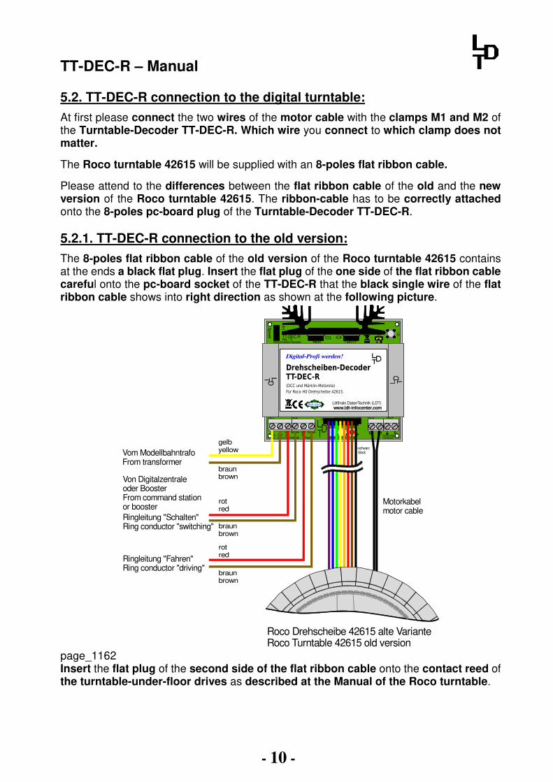
5.2. TT-DEC-R connection to the digital turntable:
At first please connect the two wires of the motor cable with the clamps M1 and M2 of the Turntable-Decoder TT-DEC-R. Which wire you connect to which clamp does not matter.
The Roco turntable 42615 will be supplied with an 8-poles flat ribbon cable.
Please attend to the differences between the flat ribbon cable of the old and the new version of the Roco turntable 42615. The ribbon-cable has to be correctly attached onto the 8-poles pc-board plug of the Turntable-Decoder TT-DEC-R. 5.2.1. TT-DEC-R connection to the old version:
The 8-poles flat ribbon cable of the old version of the Roco turntable 42615 contains at the ends a black flat plug. Insert the flat plug of the one side of the flat ribbon cable careful onto the pc-board socket of the TT-DEC-R that the black single wire of the flat ribbon cable shows into right direction as shown at the following picture.
Von Digitalzentrale oder BoosterFrom command stationor booster
braunbrown
Vom ModellbahntrafoFrom transformer
gelbyellow
Ringleitung "Fahren"Ring conductor "driving"
Ringleitung "Schalten"Ring conductor "switching" braun
brown
rotred
rotred
braunbrown
Roco Drehscheibe 42615 alte VarianteRoco Turntable 42615 old version
Motorkabelmotor cable
Z805 LM317IC3
Speed
P1
IC4
S1
Littfinski DatenTechnik (LDT)
K J
LED1
+red brown
ST4
+ +LED2 LED3
green yellow red
ARückmeldg.Feedback
M1M2K Jred brown
Commands Track
KL3 KL4KL2KL1
TT-DEC-RRev. 1.2
JP1
Drehscheiben-Decoder
16...18V~22...24V=
+ ~ - ~
2L 3L
(DCC und Märklin-Motorola)
Für Roco H0 Drehscheibe 42615.
Drehscheiben-DecoderTT-DEC-R
Digital-Profi werden!
Littfinski DatenTechnik (LDT)www.ldt-infocenter.com
Multi-Digital
schwarzblack
page_1162 Insert the flat plug of the second side of the flat ribbon cable onto the contact reed of the turntable-under-floor drives as described at the Manual of the Roco turntable.

TT-DEC-R – Manual
- 11 -
5.2.2. TT-DEC-R connection to the new version:
The 8-poles flat ribbon cable of the new version of the Roco turntable 42615 contains on each side a gray flat plug. Insert the flat plug careful onto the pc-board socket of the TT-DEC-R in direction that the black single wire of the flat ribbon cable is showing to the left as shown at the following pictures.
Von Digitalzentrale oder BoosterFrom command stationor booster
braunbrown
Vom ModellbahntrafoFrom transformer
gelbyellow
Ringleitung "Fahren"Ring conductor "driving"
Ringleitung "Schalten"Ring conductor "switching" braun
brown
rotred
rotred
braunbrown
Roco Drehscheibe 42615 neue VarianteRoco Turntable 42615 new version
Z805 LM317IC3
Speed
P1
IC4
S1
Littfinski DatenTechnik (LDT)
K J
LED1
+red brown
ST4
+ +LED2 LED3
green yellow red
ARückmeldg.Feedback
M1M2K Jred brown
Commands Track
KL3 KL4KL2KL1
TT-DEC-RRev. 1.2
JP1
Drehscheiben-Decoder
16...18V~22...24V=
+ ~ - ~
2L 3L
(DCC und Märklin-Motorola)
Für Roco H0 Drehscheibe 42615.
Drehscheiben-DecoderTT-DEC-R
Digital-Profi werden!
Littfinski DatenTechnik (LDT)www.ldt-infocenter.com
Multi-Digital
schwarzblack
Motorkabelmotor cable
page_1151 Insert the flat plug of the second side of the flat ribbon cable onto the contact reed of the turntable under-floor drives as described at the Manual of the Roco turntable.

TT-DEC-R – Manual
- 12 -
6. Turntable-Decoder TT-DEC-R programming:
• Important information: You can start with the first operation and with the programming only after completing all processes of the sections 1 to 5 of this manual. Setting the unit into operation without completing the processes described within section 1 to 5 of this manual can damage the Turntable-Decoder TT-DEC-R and your turntable.
Please proceed with the programming during the first operation exactly in accordance to the sequences described within the following. If you skip one of the following sections you can not expect an exact control of the digital function of your turntable via the Turntable-Decoder TT-DEC-R. 6.1. Basic address and data format programming: The TurnTable-Decoder TT-DEC-R will be controlled by accessory addresses (turnout addresses) which will be used as well for switching of turnouts or signals.
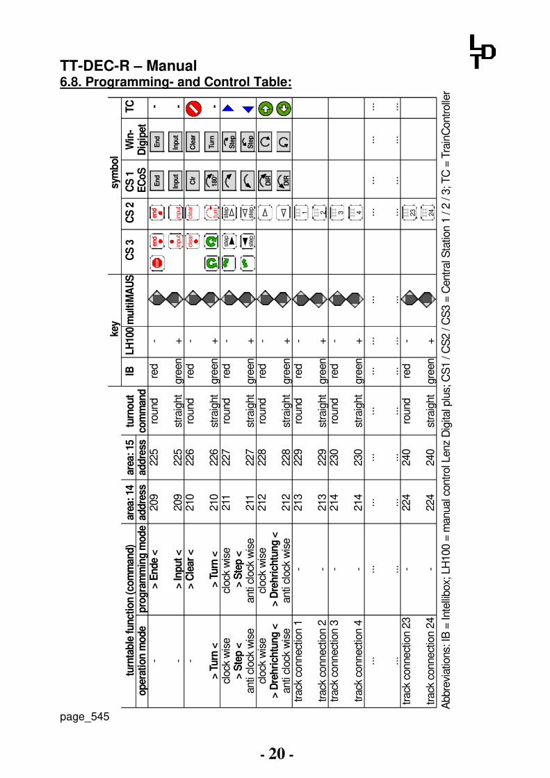
The command structure of the TT-DEC-R is compatible to the commands of the Märklin turntable-decoder 7686. The indication of the data format for the control of the TurnTable-Decoder TT-DEC-R from the command station (Märklin-Motorola or DCC) is not required. The data format will be automatically recognized from the TT-DEC-R during the following programming process of the basic address. With reference to the Märklin turntable-decoder 7686 is the TurnTable-Decoder TT-DEC-R able to use two address sections. If you use a PC-model railway software for the control of the turntable you find mostly for the two address sections the instruction of 14 and 15. With this selection is it possible to operate 2 turntables via 2 TurnTable-Decoders TT-DEC-R on your layout. The address section 14 covers the addresses 209 till 220 and the section 15 covers the addresses 225 till 236. Only by using the full capacity of the turntable with 40 track connections all addresses within the selected address section will be required. If you use a multi-protocol command station which is able to send several data formats you have to take care that all addresses within the selected address section will be adjusted uniform to Märklin-Motorola or DCC. A table showing the coherence between address section, address and turntable-function can be found at chapter 6.8. “Programming- and Control-Table” within this operation instruction. This table gives you as well the information about the symbols (if required) your model railway software uses for the various turntable functions.

TT-DEC-R – Manual
- 13 -
Programming process:
1. Switch-on your digital-layout and the TurnTable-Decoder TT-DEC-R. If you want to perform the programming of the TT-DEC-R via your model railway software you have to switch-on those and adjust the turntable if required at first in accordance to the relevant instruction of the software. It is important that your model railway software supports the Märklin-turntable decoder 7686 because the TT-DEC-R is compatible to the commands of the Märklin decoder.
2. Please press shortly 1-times the key S1 which is located at the right side next to the TT-DEC-R heat-sink. Now the yellow LED will flash.
3. Send now several times the command >Drehrichtung< (Turning Direction) at clockwise direction or anti clockwise from your digital command station or from your model railway software in accordance to the programming- and control table (chapter 6.8.). If the TT-DEC-R has recognized the command after several times sending the command this will be indicated a switched-off yellow LED. This process initiates that the TT-DEC-R will be correct programmed to the required digital format (Märklin-Motorola or DCC) and the address range (14 or 15).
4. The TT-DEC-R will leave the programming mode automatically. All three light emitting diodes will glow.
6.2. Turning direction testing: For testing the turning direction you have to send the command >Step< (clock wise) via your digital command station or via your model railway software. The turntable bridge will turn clockwise to the next track connection. If the bridge will turn anti-clockwise to the next track connection please switch off the model railway transformer which supplies the Turntable-Decoder TT-DEC-R. Now exchange the two wires of the motor cables at the clamps M1 and M2. Switch-on the model railway transformer and send again the command >Step< at clockwise direction. Now shall the bridge turn correct onto the next track connection. 6.3. Track connection programming:
Please attend: The adjustment of the turntable bridge turning direction has to be completed in accordance to section 6.2 to assure the clock-wise turning of the turntable bridge to the next track connection by each >Step< command before starting with the programming of the track connections.
By programming the track connections you have to prepare your TurnTable-Decoder TT-DEC-R to be able to recognize all available track connections and to turn the turntable bridge to the required track connection during the operation. The turntable can be equipped with 4 to 40 track connections.

TT-DEC-R – Manual
- 14 -
Non-aligned opposite track connections can have an offset with a minimum angle of 4.5 degree.
Roco Drehscheibe 42615Roco Turntable 42615
min. 4,5°
page_1159 During the programming process please define one track connection as track 1 as a so-called reference track. Programming process:
1. Press 2-times shortly the key S1. The green LED flashes. 2. Send now the command >Input<. The red LED will switch off shortly and the
turntable turns eventually to the last programmed reference track. 3. Turn now the turntable with the >Step< commands (clockwise or anti clockwise)
to the track 1 (reference track). 4. Send now the command >Clear< for storing the position of track 1 (reference
track). The red LED will be shortly switched off. 5. Turn now the turntable with the command >Step< clockwise to the next available
track connection. Consider as well single opposite track connections. 6. Store now the track connection with the command >Input<. The red LED will be
switched off shortly. 7. Set-up further track connections by following the same procedure. 8. You will have programmed all track connections if the bridge has reached the
last track connection before the bridge will turn clockwise to the reference track by the next >Step< command but turned by 180 degree. Send additionally for the last track connection the command >End<. The turntable bridge turns to the track connection 1 (reference track) and the programming mode will be closed. If the turntable bridge will not turn back to the reference track please repeat the programming process.
TT-DEC-R – Manual
- 15 -
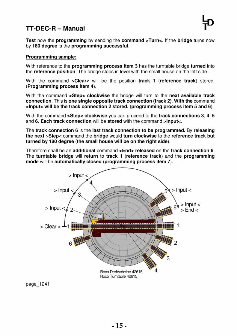
Test now the programming by sending the command >Turn<. If the bridge turns now by 180 degree is the programming successful. Programming sample:
With reference to the programming process item 3 has the turntable bridge turned into the reference position. The bridge stops in level with the small house on the left side.
With the command >Clear< will be the position track 1 (reference track) stored. (Programming process item 4).
With the command >Step< clockwise the bridge will turn to the next available track connection. This is one single opposite track connection (track 2). With the command >Input< will be the track connection 2 stored. (programming process item 5 and 6).
With the command >Step< clockwise you can proceed to the track connections 3, 4, 5 and 6. Each track connection will be stored with the command >Input<.
The track connection 6 is the last track connection to be programmed. By releasing the next >Step< command the bridge would turn clockwise to the reference track but turned by 180 degree (the small house will be on the right side).
Therefore shall be an additional command >End< released on the track connection 6. The turntable bridge will return to track 1 (reference track) and the programming mode will be automatically closed (programming process item 7).
Roco Drehscheibe 42615Roco Turntable 42615
1> Clear <
> Input < 2
3> Input <
4> Input <
> Input <5
> Input <> End <6
1
2
3
4
6
page_1241
TT-DEC-R – Manual
- 16 -
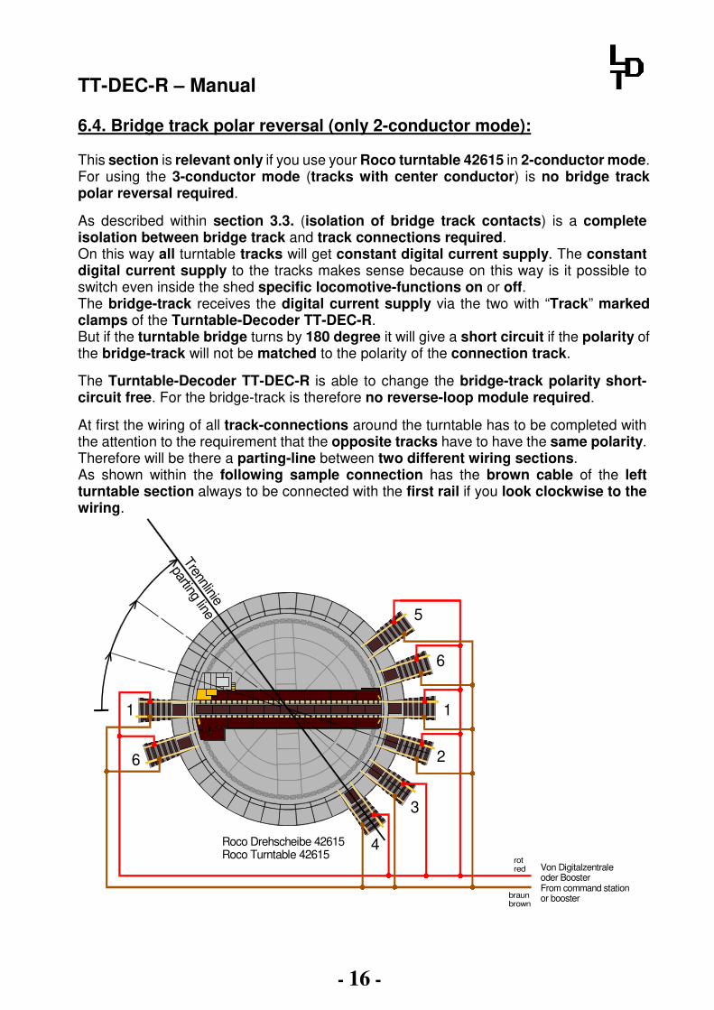
6.4. Bridge track polar reversal (only 2-conductor mode): This section is relevant only if you use your Roco turntable 42615 in 2-conductor mode. For using the 3-conductor mode (tracks with center conductor) is no bridge track polar reversal required.
As described within section 3.3. (isolation of bridge track contacts) is a complete isolation between bridge track and track connections required. On this way all turntable tracks will get constant digital current supply. The constant digital current supply to the tracks makes sense because on this way is it possible to switch even inside the shed specific locomotive-functions on or off. The bridge-track receives the digital current supply via the two with “Track” marked clamps of the Turntable-Decoder TT-DEC-R. But if the turntable bridge turns by 180 degree it will give a short circuit if the polarity of the bridge-track will not be matched to the polarity of the connection track.
The Turntable-Decoder TT-DEC-R is able to change the bridge-track polarity short-circuit free. For the bridge-track is therefore no reverse-loop module required.
At first the wiring of all track-connections around the turntable has to be completed with the attention to the requirement that the opposite tracks have to have the same polarity. Therefore will be there a parting-line between two different wiring sections. As shown within the following sample connection has the brown cable of the left turntable section always to be connected with the first rail if you look clockwise to the wiring.
Trennlinie
parting line
Roco Drehscheibe 42615Roco Turntable 42615
1
5
6
1
2
3
4
6
Von Digitalzentraleoder BoosterFrom command station or booster
rotred
braunbrown

TT-DEC-R – Manual
- 17 -
At the right turntable section has the red digital cable always to be connected to the first rail if looking to the wiring in clockwise direction.
If the turntable bridge is passing the parting-line between the two wiring sections the Turntable-Decoder TT-DEC-R will change the polarity of the bridge track provided that you programmed the parting-line. At the sample connection will be the parting-line on the track 4 because the polarity has to be changes if clockwise turning after track 4 and anti-clockwise after track 5 has the polarity to be changed. Programming process:
1. Turn the turntable bridge to the reference position. Now all LED will lighten. 2. Activate now 2 times shortly the key S1. The green LED flashes.
Turn now the turntable bridge clockwise with the command >Step< to the track connection with the imagined parting-line.
3. Send now the command >Turning direction< clockwise or anti clockwise. The boarding line will be stored and the programming mode closed. The turning bridge will turn now automatically to the track connection 1.
4. Check: Send the command >Turn< clockwise. When the turning bridge passes the parting-line (at the sample at track 4) the red LED will be shortly switched off.
TT-DEC-R – Manual
- 18 -
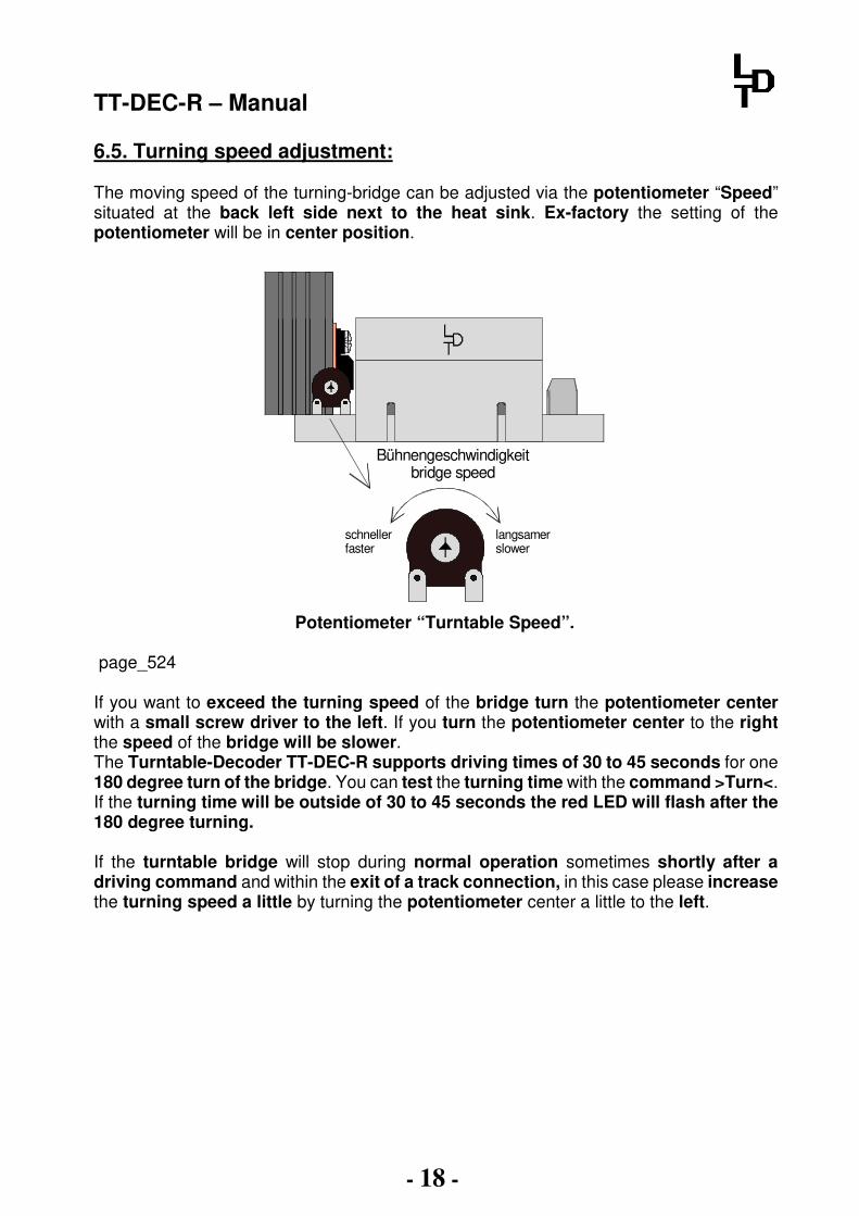
6.5. Turning speed adjustment: The moving speed of the turning-bridge can be adjusted via the potentiometer “Speed” situated at the back left side next to the heat sink. Ex-factory the setting of the potentiometer will be in center position.
schnellerfaster
langsamerslower
Bühnengeschwindigkeitbridge speed
Potentiometer “Turntable Speed”.
page_524
If you want to exceed the turning speed of the bridge turn the potentiometer center with a small screw driver to the left. If you turn the potentiometer center to the right the speed of the bridge will be slower. The Turntable-Decoder TT-DEC-R supports driving times of 30 to 45 seconds for one 180 degree turn of the bridge. You can test the turning time with the command >Turn<. If the turning time will be outside of 30 to 45 seconds the red LED will flash after the 180 degree turning. If the turntable bridge will stop during normal operation sometimes shortly after a driving command and within the exit of a track connection, in this case please increase the turning speed a little by turning the potentiometer center a little to the left.
TT-DEC-R – Manual
- 19 -
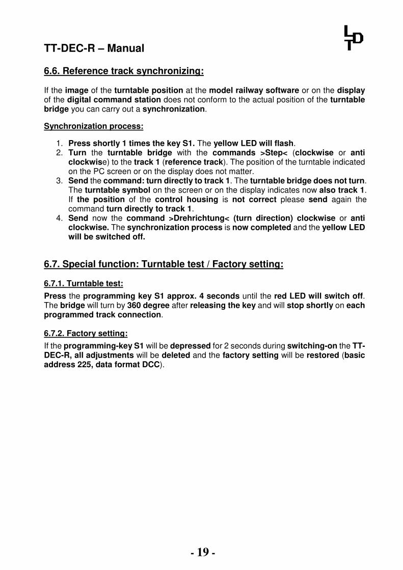
6.6. Reference track synchronizing: If the image of the turntable position at the model railway software or on the display of the digital command station does not conform to the actual position of the turntable bridge you can carry out a synchronization.
Synchronization process:
1. Press shortly 1 times the key S1. The yellow LED will flash. 2. Turn the turntable bridge with the commands >Step< (clockwise or anti
clockwise) to the track 1 (reference track). The position of the turntable indicated on the PC screen or on the display does not matter.
3. Send the command: turn directly to track 1. The turntable bridge does not turn. The turntable symbol on the screen or on the display indicates now also track 1. If the position of the control housing is not correct please send again the command turn directly to track 1.
4. Send now the command >Drehrichtung< (turn direction) clockwise or anti clockwise. The synchronization process is now completed and the yellow LED will be switched off.
6.7. Special function: Turntable test / Factory setting: 6.7.1. Turntable test:
Press the programming key S1 approx. 4 seconds until the red LED will switch off. The bridge will turn by 360 degree after releasing the key and will stop shortly on each programmed track connection. 6.7.2. Factory setting:
If the programming-key S1 will be depressed for 2 seconds during switching-on the TT-DEC-R, all adjustments will be deleted and the factory setting will be restored (basic address 225, data format DCC).
TT-DEC-R – Manual
- 20 -
6.8. Programming- and Control Table:
ST
OP
area
: 14
add
ress
209
209
210
210
211
211
212
212
213
213
214
214
... ... 224
224
op
erat
ion
mo
de
- - -
> T
urn
<cl
ock
wis
e> S
tep
<an
ti cl
ock
wis
ecl
ock
wis
e> D
reh
rich
tun
g <
anti
cloc
k w
ise
track
con
nect
ion
1
track
con
nect
ion
2tra
ck c
onne
ctio
n 3
track
con
nect
ion
4... ...
track
con
nect
ion
23
track
con
nect
ion
24
IB red
gree
nre
d
gree
nre
d
gree
nre
d
gree
nre
d
gree
nre
d
gree
n... ... red
gree
n
turn
out
com
man
dro
und
stra
ight
roun
d
stra
ight
roun
d
stra
ight
roun
d
stra
ight
roun
d
stra
ight
roun
d
stra
ight
... ...ro
und
stra
ight
area
: 15
add
ress
225
225
226
226
227
227
228
228
229
229
230
230
... ... 240
240
pro
gra
mm
ing
mod
e> E
nd
e <
> In
pu
t <
> C
lear
<
> T
urn
<cl
ock
wis
e > S
tep
<an
ti cl
ock
wis
e cl
ock
wis
e > D
reh
rich
tun
g <
anti
cloc
k w
ise
- - - - ... ... - -
turn
tab
le f
un
ctio
n (
com
man
d)
LH
100
- + - + - + - + - + - + ... ... - +
mu
ltiM
AU
S
... ...
Abb
revi
atio
ns: I
B =
Inte
llibo
x; L
H10
0 =
man
ual c
ontro
l Len
z D
igita
l plu
s; C
S1
/ CS
2 / C
S3
= C
entr
al S
tatio
n 1
/ 2 /
3; T
C =
Tra
inC
ontro
ller
DIR
DIR
180°
Clr
Inp
ut
En
d ... ...
CS
1
EC
oS
En
d
Cle
ar
Inp
ut
Turn
Win
-D
igip
etT
C - - -
CS
2
... ...
... ...
Ste
p
Ste
p
sym
bo
lke
y
CS
3
end
inpu
t
clea
r
turn
step
step 1 2 3 4 23 24... ...
end
inpu
t
clea
r
step
step
page_545

TT-DEC-R – Manual
- 21 -
7. Feedback Reports:
The Turntable-Decoder TT-DEC-R is able to transmit the information “Bridge track occupied” and “Position reached” to Feedback Modules. This feedback information can be used from a digital command station or from a model railway software for further automatic control of the turntable. The turntable bridge track receives digital current supply from the clamps “Track” via the Turntable-Decoder TT-DEC-R. If the clamp “Track” is connected to the output of a Track Occupancy Detector (e.g. GBM-8) or to a Feedback Module with integrated track occupancy report (e.g. RM-GB-8-N or RS-8) there will be a feedback report “Bridge Track occupied” whenever a locomotive receives digital current on the bridge track. If the turntable bridge has reached the required position the Turntable-Decoder TT-DEC-R will send a feedback signal to the 2-poles clamp KL4 which is marked with “Feedback”. This signal can be evaluated from the model railway software and used for further control actions. The following sample connections will show the required wiring for the new version of the Roco Turntable 42615 which can be used as well for the old version. The shown wiring can be used for the Turntable-Decoder TT-DEC-R in connection with Feedback Modules as well for the 3-conductor operation. You can find on the following pages and at our Web-Site at the section “Sample Connections” at the Turntable Decoder TT-DEC-R further colored wiring samples for the old and the new version of the Roco Turntable.
7.1. Feedback Reports “Position reached” and “Bridge Track occupied” with Track Occupancy Detector GBM-8 in connection with Roco Feedback Module 10787:
braunbrown
Vom ModellbahntrafoFrom transformer
gelbyellow
5 6 7 8 J K
Littfinski DatenTechnik (LDT)GBM-8
J 1 2 3 4K
Zu d
en
Gle
isen
To the tra
cks
5 6 7 8+ 1 2 3 4 +
Rev. 1.08-fach Gleisbelegt-melderOctal occupancydetector
Zum direkten Anschluss an die RückmeldemoduleRM-88-N-O/RM-DEC-88-O und Roco 10787.
8-fach GleisbelegtmelderGBM-8
Digital-Profi werden!
www.ldt-infocenter.comLittfinski DatenTechnik (LDT)
rotred
� �
rotred
�
Überwachte Bereiche imUmfeld der Drehscheibe
monitored areas within turntable
Diode 1N4003 Bestellbezeichnung: 1N4003Diode 1N4003 Order code: 1N4003
Widerstand 1,5KOhm /0,6WBestellbezeichnung: Res1K5Resistor 1,5KOhm /0,6WOrder code: Res1K5
10787
BU
S
87654321
++
BU
S
87654321
Von Zentrale oder Booster From command station or booster
Roco RückmeldebusRoco feedback bus
Von Digitalzentrale oder BoosterFrom command stationor boosterRingleitung "Schalten"Ring conductor "switching" braun
brown
rotred
Z805 LM317IC3
Speed
P1
IC4
S1
Littfinski DatenTechnik (LDT)
K J
LED1
+red brown
ST4
+ +LED2 LED3
green yellow red
ARückmeldg.Feedback
M1M2K Jred brown
Commands Track
KL3 KL4KL2KL1
TT-DEC-RRev. 1.2
JP1
Drehscheiben-Decoder
16...18V~22...24V=
+ ~ - ~
2L 3L
(DCC und Märklin-Motorola)
Für Roco H0 Drehscheibe 42615.
Drehscheiben-DecoderTT-DEC-R
Digital-Profi werden!
Littfinski DatenTechnik (LDT)www.ldt-infocenter.com
Multi-Digital
Roco Drehscheibe 42615 neue VarianteRoco Turntable 42615 new version
schwarzblack
Motorkabelmotor cable
page_1153
“Position reached” and “Bridge Track occupied” with GBM-8 and Roco 10787

TT-DEC-R – Manual
- 22 -
7.2. Feedback Reports “Position reached” and “Bridge Track occupied” with Feedback Module RS-8 for the RS-Feedback bus (Lenz Digital plus):
Überwachte Bereiche imUmfeld der Drehscheibe
monitored areas within turntable
Z805 LM317IC3
Speed
P1
IC4
S1
Littfinski DatenTechnik (LDT)
K J
LED1
+red brown
ST4
+ +LED2 LED3
green yellow red
ARückmeldg.Feedback
M1M2K Jred brown
Commands Track
KL3 KL4KL2KL1
TT-DEC-RRev. 1.2
JP1
Drehscheiben-Decoder
16...18V~22...24V=
+ ~ - ~
2L 3L
(DCC und Märklin-Motorola)
Für Roco H0 Drehscheibe 42615.
Drehscheiben-DecoderTT-DEC-R
Digital-Profi werden!
Littfinski DatenTechnik (LDT)www.ldt-infocenter.com
Multi-Digital
8-fach Rückmeldemodulmit Gleisbesetztmeldern8-fold feedback modulewith occupancy detectors
RS-8Rev. 3.2
1 2 3 4 5 6 7 8IN1 IN2
LED1
J K J K
Littfinski DatenTechnik (LDT)R S14 ..18V~S1
KL7 KL8
8-fach Rückmeldemodul mit integrierten Gleisbelegtmeldern für den RS-Rückmeldebus.8-fold feedback module with occupancy detectors for RS-feedback bus.
RS-8Rückmeldemodul / Feedback module
Digital-Profi werden!
Littfinski DatenTechnik (LDT)www.ldt-infocenter.com
Von Digitalzentrale oder BoosterFrom command stationor booster
braunbrown
Vom ModellbahntrafoFrom transformer
gelbyellow
Roco Drehscheibe 42615 neue VarianteRoco Turntable 42615 new version
schwarzblack
Ringleitung "Schalten"Ring conductor "switching" braun
brown
rotred Motorkabel
motor cable
braunbrown J
rotredK
rotred
� �
rotred
�
Von Digitalzentraleoder BoosterRingleitung "Fahren"From command stationor boosterRing conductor "driving"
Diode 1N4003 Bestellbezeichnung: 1N4003Diode 1N4003 Order code: 1N4003
Widerstand 1,5KOhm /0,6WBestellbezeichnung: Res1K5Resistor 1,5KOhm /0,6WOrder code: Res1K5
R SVon LZ100/LVZ100From LZ100/LVZ100
Vom ModellbahntrafoFrom transformer
page_1181
“Position reached” and “Bridge Track occupied” with Feedback Module RS-8 7.5. Feedback reports “Position reached” and “Bridge Track occupied” with Feedback Module RM-GB-8-N for the s88-Feeedback bus:
Überwachte Bereiche imUmfeld der Drehscheibe
monitored areas within turntable
8-fach Rückmeldemodulmit Gleisbesetztmeldern8-fold feedback modulewith occupancy detectors
RM-GB-8-NRev. 1.1
1 2 3 4 5 6 7 8IN1 IN2
IN
ST2ST1s88-N
OUT IN
s88-N
OUT
BU1 BU2
8-fach Rückmeldemodul mit integrierten Gleisbelegtmeldern für den s88-Rückmeldebus. 8-fold feedback module with occupancy detectors for s88-feedback bus.
RM-GB-8-NRückmeldemodul / Feedback module
Littfinski DatenTechnik (LDT)
Digital-Profi werden!
s88-Nwww.ldt-infocenter.com
Z805 LM317IC3
Speed
P1
IC4
S1
Littfinski DatenTechnik (LDT)
K J
LED1
+red brown
ST4
+ +LED2 LED3
green yellow red
ARückmeldg.Feedback
M1M2K Jred brown
Commands Track
KL3 KL4KL2KL1
TT-DEC-RRev. 1.2
JP1
Drehscheiben-Decoder
16...18V~22...24V=
+ ~ - ~
2L 3L
(DCC und Märklin-Motorola)
Für Roco H0 Drehscheibe 42615.
Drehscheiben-DecoderTT-DEC-R
Digital-Profi werden!
Littfinski DatenTechnik (LDT)www.ldt-infocenter.com
Multi-Digital
Von Digitalzentrale oder BoosterFrom command stationor booster
braunbrown
Vom ModellbahntrafoFrom transformer
gelbyellow
Roco Drehscheibe 42615 neue VarianteRoco Turntable 42615 new version
schwarzblack
Ringleitung "Schalten"Ring conductor "switching" braun
brown
rotred Motorkabel
motor cable
braunbrown J
rotredK
rotred
� �
rotred
�
Von Digitalzentraleoder BoosterRingleitung "Fahren"From command stationor boosterRing conductor "driving"
Diode 1N4003 Bestellbezeichnung: 1N4003Diode 1N4003 Order code: 1N4003
Widerstand 1,5KOhm /0,6WBestellbezeichnung: Res1K5Resistor 1,5KOhm /0,6WOrder code: Res1K5
page_1177
“Position reached” and “bridge track occupied” with Feedback Module RM-GB-8-N
TT-DEC-R – Manual
- 23 -
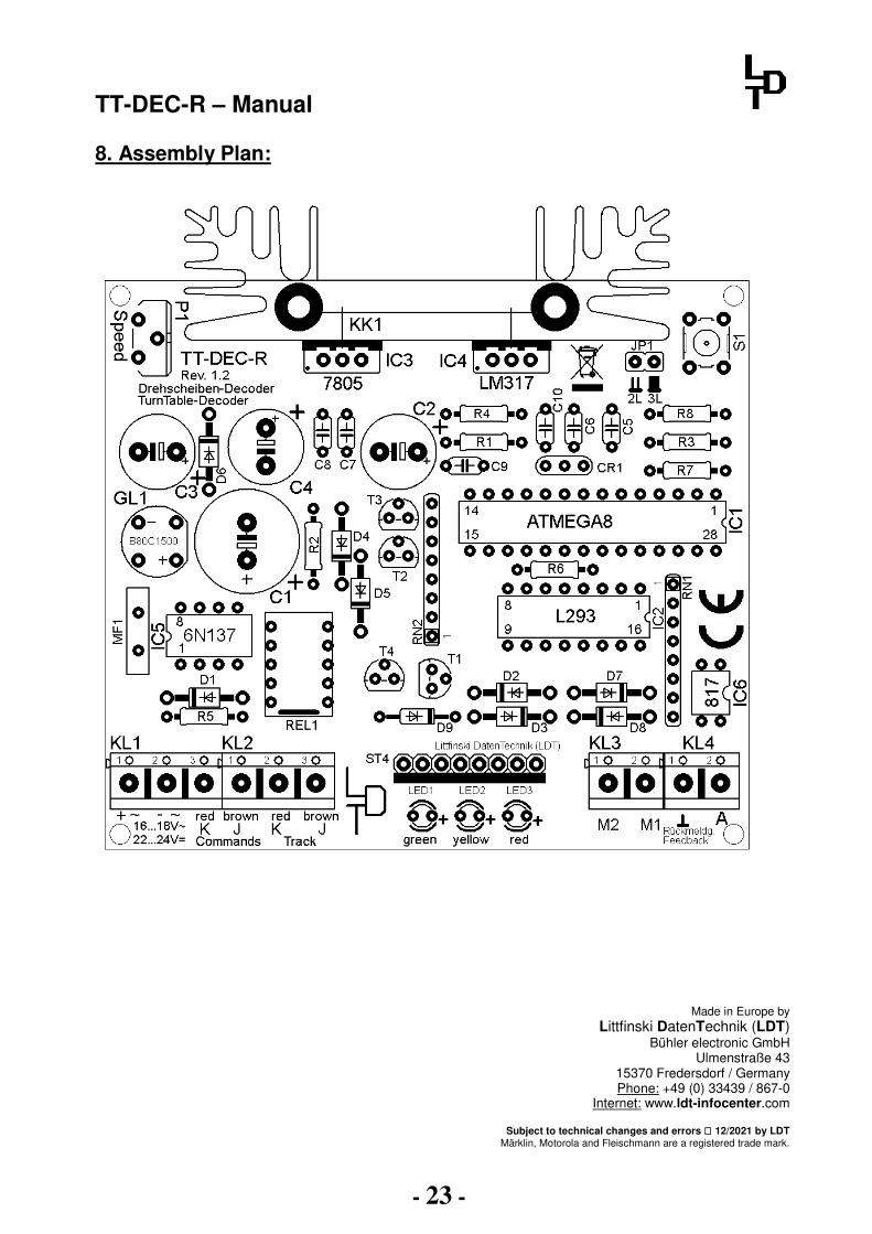
8. Assembly Plan:
Made in Europe by Littfinski DatenTechnik (LDT)
Bühler electronic GmbH Ulmenstraße 43
15370 Fredersdorf / Germany Phone: +49 (0) 33439 / 867-0
Internet: www.ldt-infocenter.com
Subject to technical changes and errors 12/2021 by LDT Märklin, Motorola and Fleischmann are a registered trade mark.