l california iso · 2011/05/27 · l california iso shc ke{ fjk, california independent system...
TRANSCRIPT

L California ISO Shc ke{ Fjk,
California Independent System Operator Corporation
Via E-mail
May 27, 2011
Carlos Aguilar Senior Vice President of Global Development BrightSource Energy, Inc. 1999 Harrison Street, Suite 200 Oakland, CA 94612
Subject: Palo Verde Mesa Project Cluster 3 Phase I Interconnection Study
Dear Mr.Aguilar:
Attached is the Cluster 3 Phase I Interconnection Study Report for the interconnection of the proposed Palo Verde Mesa Project (Project) to the CAISO Controlled Grid. The CAISO and SCE performed the Phase I Interconnection Study in accordance with the CAISO’s GIP tariff.
The study has identified that the Project contributes to the need for Network Upgrades in accordance with the CAISO’s GIP tariff. A non-binding cost estimate of the Network Upgrades is provided in the study report. In addition, the study report provides a non-binding cost estimate of the Interconnection Facilities and Distribution System Upgrades to interconnect the Project to the CAISO Controlled Grid.
Please review the report and prepare comments and questions for the Results Meeting. The Interconnection Study Results Meeting will be coordinated and scheduled within 30 calendar days following receipt of this Interconnection Study report.
Sincerely,
K Robert Sparks, P.E. Manager Regional Transmission-South
Attachments
cc: via e-mail: Carlos Aguilar (caguilarbrightsourceenergy.com ) Diane Llamas (Diane.Llamassce.com ) Berry Curry (Berry. Currysce.com ) Eduyng Castano (EduyngCastanosce.com ) John Tucker ([email protected] ) Ying He (Ying.He(sce.com ) Ayman Samaan (AymanSamaantsce.com )
CAISO 250 Outcropping Way
Folsom, CA 95630 (916) 351-4416

Judy Brown (J Brown (caiso.com ) Linda Wright (LWriqhtcaiso.com ) Robert Emmert(remmed(caiso.com ) CAISO Regional Transmission South CAISO Regional Transmission North
CMSO 250 Outcropping Way
Folsom, CA 95630 (916) 351-4416

Appendix A – Q #643AC
Palo Verde Mesa, LLC
Palo Verde Mesa
Queue Cluster 3 Phase I Final Report
May 27, 2011
This study has been completed in coordination with Southern California Edison per CAISO Tariff Appendix Y Generator Interconnection Procedures (GIP) for Interconnection Requests in a Queue Cluster Window

Table of Contents
1. Executive Summary ........................................................................................................ 2 2. Project and Interconnection Information ..................................................................... 3 3. Study Assumptions ........................................................................................................ 5 4. Power Flow Analysis ...................................................................................................... 6 5. Short Circuit Analysis ..................................................................................................... 8
5.1 Short Circuit Study Input Data ................................................................................................... 8
5.2 Results ........................................................................................................................................ 9
5.3 Preliminary Protection Requirements ........................................................................................ 9
6. Reactive Power Deficiency Analysis ............................................................................ 9 7. Transient Stability Evaluation ...................................................................................... 10
7.1 Transient Stability Study Scenarios ........................................................................................ 10
7.2 Results ..................................................................................................................................... 10
8. Deliverability Assessment ........................................................................................... 11 9. Environmental Evaluation/Permitting ......................................................................... 11 10. Upgrades, Cost Estimates and Construction schedule estimates ......................... 11 11. Items not covered in this study ................................................................................... 16 Attachments:
1. Generator Machine Dynamic Data 2. Dynamic Stability Plots (see Appendix F of the Group Report) 3. SCE Interconnection Handbook 4. Short Circuit Calculation Study Results (see Appendix H of the Group Report) 5. Deliverability Assessment Results 6. Allocation of Network Upgrades for Cost Estimates

2
1. Executive Summary
Palo Verde Mesa, LLC an Interconnection Customer (IC), has submitted a completed Interconnection Request (IR) to the California Independent System Operator Corporation (CAISO) for their proposed Palo Verde Mesa (Project), interconnecting to the CAISO Controlled Grid. The Project is a Full Delivery, Steam Turbine plant with a total rated output of 750 MW to the proposed Point of Interconnection (POI) at Southern California Edison Company’s (SCE) Colorado River 230 kV substation in Blythe, California. The customer has requested an In-Service date of July 01, 2014 and a Commercial Operation Date of January 1, 2015.
In accordance with Federal Energy Regulatory Commission (FERC) approved Generator Interconnection Procedures (GIP) for Interconnection Requests in a Queue Cluster Window (CAISO Appendix Y), the Project was grouped with Queue Cluster 3 Phase I Study (QC3) projects to determine the impacts of the group as well as impacts of the Project on the CAISO Controlled Grid.
The group report has been prepared separately identifying the combined impacts of all projects in the group on the CAISO Controlled Grid. This report focuses only on the impacts of this Project.
The report provides the following:
1. Transmission system impacts caused by the Project;
2. System reinforcements necessary to mitigate the adverse impacts caused by the Project under various system conditions;
3. A list of required facilities and a non-binding, good faith estimate of the Project’s cost responsibility and time to construct these facilities.
The QC3 study has determined that the Project contributes to various reliability and/or deliverability problems for which mitigation plans have been proposed. These mitigation plans are detailed in Section 10 of this report.
The non-binding cost estimate of Interconnection Facilities1 to interconnect the Project is approximately $ 29,046,000 including ITCC2. The maximum cost responsibility for the SCE Network Upgrades3 to interconnect the Project is $460,988,900 and the cost of the SCE Distribution Upgrades4 is $11,009,000.
1 The transmission facilities necessary to physically and electrically interconnect the Project to the CAISO Controlled
Grid at the point of interconnection. 2 Income Tax Component of Contribution. The ITCC included in this cost estimate was computed using a 35% rate.
Due to the enactment of H.R. 4853, the Tax Relief, Unemployment Insurance Reauthorization and Job Creation Act of 2010, and upon formal acceptance by the CPUC of SCE’s advice letter (filed on December 27, 2010), this rate may change for electric CIAC recorded or received after September 8, 2010 through December 31, 2011.
3 The SCE transmission facilities, other than Interconnection Facilities, beyond the point of interconnection necessary to physically and electrically interconnect the Project safely and reliably to the CAISO Controlled Grid
4 These upgrades are not identified in ISO tariff, and are not reimbursable.
3
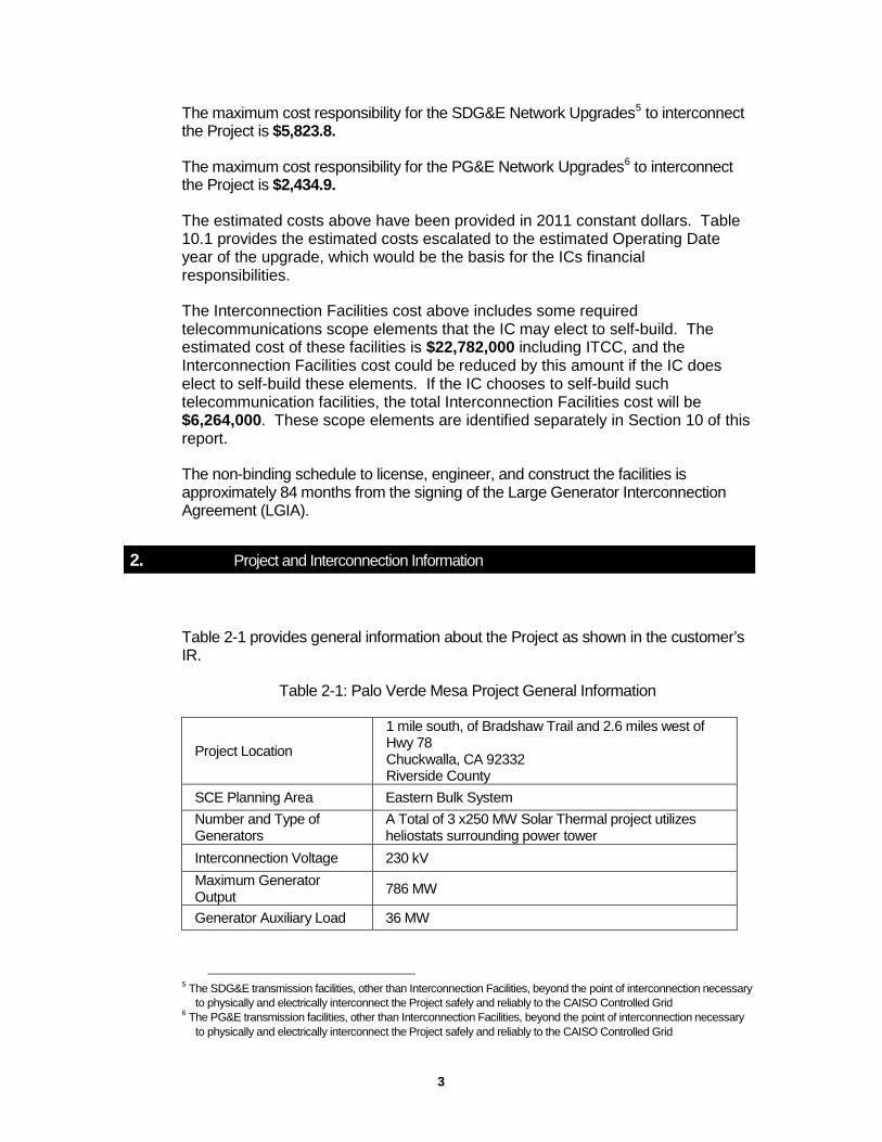
The maximum cost responsibility for the SDG&E Network Upgrades5 to interconnect the Project is $5,823.8.
The maximum cost responsibility for the PG&E Network Upgrades6 to interconnect the Project is $2,434.9.
The estimated costs above have been provided in 2011 constant dollars. Table 10.1 provides the estimated costs escalated to the estimated Operating Date year of the upgrade, which would be the basis for the ICs financial responsibilities.
The Interconnection Facilities cost above includes some required telecommunications scope elements that the IC may elect to self-build. The estimated cost of these facilities is $22,782,000 including ITCC, and the Interconnection Facilities cost could be reduced by this amount if the IC does elect to self-build these elements. If the IC chooses to self-build such telecommunication facilities, the total Interconnection Facilities cost will be $6,264,000. These scope elements are identified separately in Section 10 of this report.
The non-binding schedule to license, engineer, and construct the facilities is approximately 84 months from the signing of the Large Generator Interconnection Agreement (LGIA).
2. Project and Interconnection Information
Table 2-1 provides general information about the Project as shown in the customer’s IR.
Table 2-1: Palo Verde Mesa Project General Information
Project Location
1 mile south, of Bradshaw Trail and 2.6 miles west of Hwy 78 Chuckwalla, CA 92332 Riverside County
SCE Planning Area Eastern Bulk System Number and Type of Generators
A Total of 3 x250 MW Solar Thermal project utilizes heliostats surrounding power tower
Interconnection Voltage 230 kV Maximum Generator Output 786 MW
Generator Auxiliary Load 36 MW
5 The SDG&E transmission facilities, other than Interconnection Facilities, beyond the point of interconnection necessary
to physically and electrically interconnect the Project safely and reliably to the CAISO Controlled Grid 6 The PG&E transmission facilities, other than Interconnection Facilities, beyond the point of interconnection necessary
to physically and electrically interconnect the Project safely and reliably to the CAISO Controlled Grid

4
Maximum Net Output to Grid 750 MW
Power Factor Regulation Range ±0.873 per the IR
Step-up Transformer(s)
Main Transformer(s) Data (x3) 230/21 kV (YG-D), 180/240/300 MVA H-X Impedance Value: 9 % @ 180 MVA
Point of Interconnection SCE Colorado River 230 kV Bus via two Gen Ties
Commercial Operation Date January 1, 2015 (customer requested date)
Figure 2-1 provides the map for the Project and the transmission facilities in the vicinity. Figure 2-2 shows the conceptual single line diagram of the Project as modeled in the study.
Figure 2-1 : Map of the Project
Figure 2-2: Proposed Single Line Diagram

5
3. Study Assumptions
For detailed assumptions, please refer to the main report. The following assumptions are only specific to the Project:
A. The following Facilities were estimated and included in the Phase I Study: o One of two telecommunication paths from the Generating Facility to
Colorado River Substation will be installed by SCE. o The segment of No.1 and No.2 220 kV Gen Tie Lines inside the Colorado
River Substation Property Line. o The required Revenue Metering Cabinet and Retail Load Meters to be
installed at the Generating Facility will be installed by SCE. o The required Remote Terminal Unit (RTU) to be installed at the Generating
Facility will be installed by SCE.
Palo Verde Mesa TOT 496 750 MW CAPACITY
Full Capacity
GENERATOR DATA : Type of Generator : Synch . Total Rated Output : 750 MW Auxiliary Load : 36 MW Number of units : 3 Individual generator output : 262 MW MVA Rating : 500 MVA Voltage Rating : 21 kV PF : 0 . 873 lag / 0 . 93 lead Xd’’ 1 : 0 . 124 Xd’’ 2 : 0 . 129 Xd’’ 0 : 0 . 053 Grounded through impedance - R - 0 . 1668 p . u X - 0 . 0 p . u .
TRANSFORMER DATA ( 1 - 2 ): Rated Voltage : 230 / 21 kV Rated MVA : 180 / 240 / 300 MVA Impedance : 9 % @ 180 MVA H Winding : Wye - Gnd X Winding : Delta
Gen - Tie Line Data : 2 Gen tie Distance : 8 . miles Double circuit tower 1590 ACSR ( Lapwing ) Voltage : 230 kV Z 1 ( p . u .) = . 00127 + J . 01404 B = . 02927 Z 0 = . 01012 + J . 03959 B =. 02048 Mutual impedance Z 1 =. 00887 + J . 02450 B = - . 00633 Line Rating : 1113 / 1284 Amps . , 443 / 512 MVA
230 kV
21 kV
12 MW 262 MW 262 MW
12 MW 21 kV
Deliverability Status : Full Capacity
In Service Date : 7 / 1 / 2014
262 MW 12 MW
TOT 496 S 95498
TOT 496 L 1 95421
TOT 496 L 2 95422
TOT 496 L 3 95500
Colorado River 230 kV Bus
Point of Change of Ownership
Point of Interconnection Point of
Interconnection
Point of Change of Ownership
SCE Project

6
B. The following facilities are to be installed by the Interconnection Customer and are not included in this Phase I Study: o The No.1 and No.2 220 kV Gen Tie Lines from the Generating Facility to
the last structure outside the Colorado River Substation Property Line. o The No.1 and No.2 220 kV Gen Tie Lines Optical Ground Wire (OPGW)
to provide the second of the two telecommunication paths required for the Line Protection Relays and the Special Protection System (SPS).
o All required CAISO metering equipment at the Generating Facility. o All required Revenue Metering Equipment to meter the Generating
Facility Retail Load will be specified by SCE and installed by the generator at their end of the 220 kV Gen Tie Line.
o All required No.1 and No.2 220 kV Gen Tie Lines Protection Relays to be installed at the Generating Facility Switchyard will be specified by SCE and installed by the generator.
o All required Special Protection Scheme Relays to be installed at the Generating Facility will be specified by SCE and installed by the generator.
4. Power Flow Analysis
The group study indicated that the Project contributes to the following transmission facility overloads or non-convergence problems. The details of the analysis and overload levels are provided in the group study.
4.1 Overloaded Transmission Facilities
Category “A”
• The future Colorado River No.1 and No. 2 AA Bank overloads
• The future Devers – Red Bluff No.1 500 kV T/L overloads
• The future Devers – Red Bluff No.2 500 kV T/L overloads
• The future Valley – Alberhill 500 kV T/L overloads
• The future Alberhill – Serrano 500 kV T/L overloads
• The existing Lewis – Barre 220 kV T/L overloads
• NOTE: under base case conditions the following facilities result
with Low Voltage:
o Colorado River 500 kV bus
o Red Bluff 500 kV bus

7
o Serrano 500 kV bus
Category “B”
• The existing Lewis – Villa Park 220 kV T/L overloads under the Barre – Villa Park 220 kV T/L (N-1) outage
• The existing Lewis – Serrano No. 2 220 kV T/L overloads under the Lewis – Serrano No.1 220 kV T/L (N-1) outage
• The existing Devers – Red Bluff No.1 500 kV T/L overloads under Devers – Red Bluff No.2 500 kV T/L (N-1) outage
• The future Series Cap on the Devers – Red Bluff No.2 500 kV T/L overloads under the Devers – Red Bluff No.1 500 kV T/L outage
Category “C”
• The existing Lewis - Villa Park 220 kV T/L overloads under the Lewis-Serrano No. 1 and No. 2 220 kV T/Ls (N-2) outage
4.2 Power Flow Non-Convergence
There were no non-convergence issues identified by the addition of this project with all proposed system upgrades.
4.3 Recommended Mitigations
A combination of congestion management for base case overloads and SPS to trip the Project under identified contingency outage conditions is required to mitigate the power flow impacts of the Project described above. See the group report for additional details.
The scope of the mitigations assigned to the Project are as follows: (Refer to Section 10 for a brief description of the upgrades)
• Reliability Network Upgrades
o Expand QC2 SPS o New SPS – 1 o New SPS – 2 o New SPS – 4 o New SPS – 5 o Short Circuit Duty (SCD) Mitigation o Eastern Bulk System Reactive power support o Eastern Bulk System SVC o Lewis – Villa Park 220kV T/L o Lewis – Serrano 220kV T/L

8
• Delivery Network Upgrades
o New Alberhill – Serrano 500 kV T/L o New Alberhill – Valley No.2 500 kV T/L o New Colorado River – N. Gila 500 kV T/L with 50% series
compensation o Devers – Red Bluff No.1 500 kV T/L upgrades o Barre – Lewis 220 kV T/L upgrades o Colorado River 500/220 kV Transformers o Serrano 500/220 kV Transformer
• Distribution Upgrades
o Relocate Barre – Fullerton – Villa Park 66 kV Line o Relocate Barre – Kinder – Lampson 66 kV Line
5. Short Circuit Analysis
Short circuit studies were performed to determine the fault duty impact of adding the QC3 projects to the transmission system and to ensure system coordination. The fault duties were calculated with and without the projects to identify any equipment overstress conditions. Once overstressed circuit breakers are identified, the fault current contribution from each individual project in QC3 is determined. Each project in QC3 will be responsible for its share of the upgrade cost based on the rules set forth in CAISO Tariff Appendix Y.
5.1 Short Circuit Study Input Data
The following input data provided by the Applicant of the Project was used in this study:
Solar Thermal Data:
• X"1 - positive sequence subtransient reactance: 0.124 PU • X"2 - negative sequence subtransient reactance: 0.129 PU • X"0 - zero sequence subtransient reactance: 0.053 PU
Generation Step-up Transformers (total of three)
Each transformer is a three-phase, two winding 230/21 kV (YG-D), for 180/240/300 MVA OA/FA/FA @ 65° C temperature rise with the following impedance information: • H-X Impedance Value: 9 % @ 180 MVA Generation Tie Line

9
The generation tie line was assumed to be 8 miles of 1590 ACSR conductor with the following impedance information: • Z1 (p.u.) = 0.00105 + J0.01158, B=0.02424
• Z0 = 0.00797 + J0.03270, B=0.01698
This generation tie line impedance was based on SCE calculation of generation tie line electrical parameters based on the customer-provided tower and line conductor characteristics.
5.2 Results
All bus locations where the QC3 Projects increase the short-circuit duty by 0.1 kA or more and where duty is in excess of 60% of the minimum breaker nameplate rating are listed in the Group Report Appendix H. These values have been used to determine if any equipment is overstressed as a result of the QC3 interconnections and corresponding network upgrades, if any. The responsibility to finance short circuit related Reliability Network Upgrades identified through a Group Study shall be assigned to all Interconnection Requests in that Group Study pro rata on the basis of short circuit duty contribution of each Large Generating Facility. In addition, the SCD impact of the associated proposed Network Upgrades was allocated to each Large Generating Facility using the same percentage assigned for the triggered Network Upgrade. As discussed in the Group Report, the QC3 breaker evaluation identified overstressed circuit breakers at the following buses. The cost allocation for this project, based on SCD contribution at each location, is also provided:
• Five 40 kA 220 kV CBs at Kramer Substation (1.2%) • Split the 220 kV Bus at Serrano Substation (15.6%)
5.3 Preliminary Protection Requirements
Protection requirements are designed and intended to protect SCE’s system only. The preliminary protection requirements were based upon the interconnection plan as shown in Figure 2-2.
The applicant is responsible for the protection of its own system and equipment and must meet the requirements in the SCE Interconnection Handbook provided in Attachment 3.
6. Reactive Power Deficiency Analysis
Limited reactive power deficiency analysis was performed. In the base case study, serious voltage and VAR issues were identified based on system VAR

10
requirements for power flow convergence. Specifically, with addition of QC3 projects, the following VAR support is proposed:
• Two (2) -150 MVAR shunt Capacitors are needed at Red Bluff Substation 500 kV bus to maintain minimum base case voltage at Red Bluff substation
• One (1) -150 MVAR shunt Capacitor is needed at Colorado River Substation 500 kV bus to compensate for the VAR losses on the AA - Banks
• Two (2) - 150 MVAR shunt Capacitor is needed at Serrano Substation 500 kV bus to maintain voltage stability in the area.
With all proposed system upgrades listed above and in Section 4.3, the power flow studies for Category “B” and Category “C” contingencies indicated that this QC3 project did not cause voltage drops of 5% or more from the pre-project levels, or cause the SCE system to fail to meet applicable voltage criteria. This project, therefore, did not cause any adverse voltage impacts on the CAISO Controlled Grid with the proposed upgrades in place. More detailed reactive power deficiency analysis will need to be performed as part of the Phase II Study. This Project did not cause any post-transient violations with all proposed system upgrades. The proposed dynamic VAR support is discussed in section 7.
7. Transient Stability Evaluation
Limited transient stability studies were conducted using full loop base cases to ensure that the transmission system remains in operating equilibrium, as well as operating in a coordinated fashion, through abnormal operating conditions after the QC3 projects begin operation. The generator dynamic data used in the study for the Project is shown in Attachment 1. 7.1 Transient Stability Study Scenarios
Disturbance simulations were performed for a study period of 10 seconds to determine whether the QC3 projects will create any system instability during a variety of line and generator outages. The most critical single contingency and double contingency outage conditions in the Eastern Bulk System were evaluated. For the list of specific line and generator outages evaluated, see the group report.
7.2 Results
Limited stability analysis was performed for the Eastern Bulk system to identify “relative” as opposed to “absolute” conclusions regarding the stability impacts of this QC3 queued generation project. In the limited stability analysis performed in the 500 kV, 220 kV and 115 kV systems

11
with the upgrades in place to mitigate base case and outage related overload problems, the transient voltage showed unacceptable performance, and a voltage collapse under the following N-2 contingency
• Colorado River – Red Bluff No. 1 and No. 2 500 kV T/L • Red Bluff – Devers No. 1 and No. 2 500 kV T/L • Devers – Valley No.1 and No. 2 500 kV T/L • Valley – Serrano 500 kV T/L and Valley – AlberHill 500 kV T/L • Valley – Serrano 500 kV T/L and AlberHill - Serrano 500 kV T/L
To mitigate the transient voltage violations, a 550 MVAR (500 kV voltage base) dynamic VAR support is proposed at Colorado River Substation 500 kV bus. With all proposed system upgrades listed above and in Section 4.3, the QC3 Projects in SCE’s Eastern Bulk System would not cause the transmission system to go unstable under Category B and Category C outages. Stability plots are shown in Appendix F of the Group Report. More detailed stability analysis will be performed as part of the Phase II Study.
8. Deliverability Assessment
CAISO performed an On-Peak Deliverability Assessment. The power flow study results for Category “A”, “B”, and “C” are detailed in Appendix I of the Group Report. The Project contributes to multiple overloads. The details of the deliverability assessment can be found in the Appendix I of the Group Report and the Attachment 6 of the individual report.
9. Environmental Evaluation/Permitting
Please see Section 12 of group report.
10. Upgrades, Cost Estimates and Construction schedule estimates
To determine the cost responsibility of each generation project in QC3, the CAISO developed cost allocation factors based on the individual contribution of each project (Attachment 6). The cost allocation for the Interconnection Facilities and Network Upgrades for which the Project is solely responsible is as follows:
PTO’S INTERCONNECTION FACILITIES
1. Transmission: No.1 and No.2 220 kV Generation Tie Lines

12
Install one 220 kV Dead End Double Circuit Structure, two spans of conductors and OPGW between the last generator – owned structure and the Substation Dead – End Rack at the 220 kV Switchyard.
2. Substations: Colorado River Substation Install the following Interconnection Facilities Components for the termination of the new No.1 and No.2 220 kV Gen Tie Lines. Elements below are shown per line. • One Dead-End Structure. • Three 220 kV Coupling Capacitor Voltage Transformers. • Two Line Protection Relays with dedicated Digital Communication
Channels.
3. Telecommunications: Install all required light-wave, channel and related terminal equipment at each end of the Gen Tie Line.
4. Metering Services Organization Install a Revenue Metering Cabinet and Revenue Meters required to meter the Retail load at the Generating Facility.
The Generator will provide the required Metering Equipment (Voltage and Current Transformers).
5. Power System Control Install one RTU at the Generating Facility to monitor the typical Generation elements such as MW, MVAR, terminal Voltage and Circuit Breaker Status at each Generating Unit and the Plant Auxiliary Load and transmit this information to the SCE Grid Control Center.
6. Real Properties, Transmission Project Licensing, Corporate Environmental Health and Safety Organization
Obtain easements and / or acquire land, obtain licensing and permits and perform all required environmental activities for the installation of the following project elements if applicable:
• Segment of two 220 kV Gen tie lines within the Colorado River Substation
property
7. Other Required Interconnection Facilities that the IC may elect to self-build Install approximately 12 Miles of new ADSS Fiber Optic Cable from the Generating Facility to Colorado River Substation to meet the diverse routing requirements for the 220 kV Gen Tie Line Protection and SPS Relays.
Obtain easements and / or acquire land, obtain licensing and permits and perform all required environmental activities for the installation of the following project element:
• New approximate 12 miles of ADSS fiber optic cable

13
PLAN OF SERVICE RELIABILITY NETWORK UPGRADES
1. Colorado River Substation: Install two dedicated 220 kV Double Breaker Positions to terminate the Project’s two 220 kV Gen Tie Lines.
2. Power System Control: Upgrade the existing RTU at Colorado River Substation to include monitoring and control functions or the four new 220 kV Circuit Breakers.
RELIABILITY NETWORK UPGRADES
1. Existing SPS (Installed as an element of the earlier QC 2):expand QC2 proposed SPS to trip QC3 generation projects at Colorado River and/or Red Bluff for N-2 outage under losses of Colorado River – Red Bluff No. 1 & No. 2 500 kV T/Ls
2. New SPS – 1: Trips 1400 MW of generation under the double contingency (N-2) of Alberhill – Serrano No.1 and No.2 and Alberhill – Valley No.1 and No.2 500 kV T/L’s.
3. New SPS – 2 : Trips the Queued Ahead CAISO Queue #72 under the double contingency (N-2) of the Serrano – Villa Park No.1 and No.2 220 kV T/L’s
4. New SPS – 4: To by-pass the 500 kV Line Series Capacitors on the Devers – Red Bluff No.1 and No.2 and the Red Bluff – Salton Sea 500 kV T/L’s under the single contingency (N–1) caused by the outage of either one of the three 500 kV T/L’s.
5. New SPS – 5: To by-pass the 500kV Line Series Capacitors on the Salton Sea - Valley 500 kV T/L’s
6. Eastern Bulk System Reactive power support: o Install 2-150 MVAR shunt capacitors at the 500 kV bus at Serrano
Substation; o Install 2-150 MVAR shunt capacitors at the 500 kV bus at Red Bluff
Substation; o Install 1-150 MVAR Shunt capacitor at the 500 kV bus at Colorado River
Substation 7. Eastern Bulk System SVC: install one 550 MVAR (500kV Voltage Base)
Static VAR Compensator (SVC) at the 500 kV bus at Colorado River Substation
8. Lewis – Villa Park 220 kV T/L: upgrade terminal equipment 9. Lewis – Serrano 220 kV T/L: upgrade terminal equipment 10. Short Circuit Duty (SCD) Mitigation
• Serrano 220 kV Bus: split substation 220kV bus and re-arrange 220 kV lines
• Transmission Network Circuit Breaker Upgrades (SCD) Upgrade transmission network circuit breakers (pro-rata share of upgrade based on project contribution to SCD at each location). Five 40 kA 220 kV CBs at Kramer Substation
See the Group Report for additional details.
DELIVERY NETWORK UPGRADES

14
1. New Alberhill – Serrano 500 kV T/L 2. New Alberhill – Valley No.2 500 kV T/L 3. New Colorado River – N. Gila 500 kV T/L with 50% series compensation 4. Devers – Red Bluff No.1 500 kV T/L: upgrade emergency rating 5. Barre – Lewis 220 kV T/L: upgrade line from 2B-1590 to 4B-1590 6. Colorado River 500/220 kV Substation: install the 3rd and 4th 500/230 kV
banks 7. Serrano 500/220 kV Substation: Install the 4th 500/230 kV bank
See the Group Report for additional details.
DISTRIBUTION UPGRADES
1. Relocate Barre – Fullerton – Villa Park 66 kV Line 2. Relocate Barre – Kinder – Lampson 66 kV Line See the Group Report for additional details.
NEIGHBORING UTILITY UPGRADES
Reliability Network Upgrades:
SDG&E system:
• SPS to bypass series cap bank on the NG-IV 500 kV T/L
Delivery Upgrades:
SDG&E system
• Upgrade the terminal equipment for the IV-NG 500 kV line to a minimum 2749 MVA normal rating. The terminal equipment includes series capacitors, circuit breakers, current transformers, disconnects, and jumpers. Maintain the existing line compensation of 53%
• Install two 500 kV breakers, four 500 kV disconnects and protection in a breaker and half position for the new 500 kV T/L from North Gila to Colorado River
PG&E system
• Series Compensation at Gates on Los Banos-Gates #3 500kV line; and loop Los Banos-Midway 500kV line into Gates;
• Install Series Compensation at Gates on Los Banos-Gates #3 500kV line; Loop Los Banos-Midway 500 kV Line into Gates; 2 new positions at Gates 500 kV bus

15
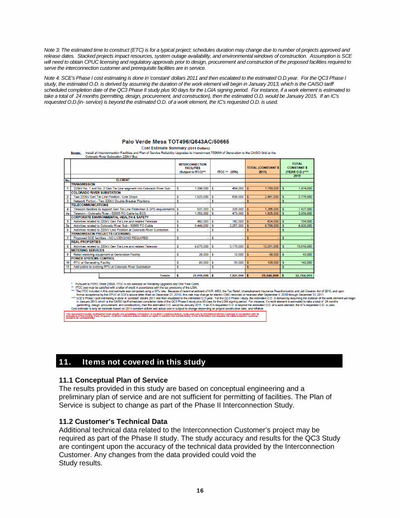
Table 10.1: Upgrades, Estimated Costs, and Estimated Time to Construct Summary
Note 1: The Interconnection Customer is obligated to fund these upgrades and will not be reimbursed.
Note 2: These upgrades are not identified in the ISO tariff, and are not reimbursable. Allocated costs may change if all projects responsible for these upgrades do not execute LGIAs.
Type of Upgrade Upgrade (May include the following) Description
Estimated Cost x 1,000
Constant Dollar (2011)
(Note 4)
Estimated
Time to Construct
(Note 3)
PTO’s Interconnection
Facilities (Note 1)
See Section 10 - PTO’S INTERCONNECTION FACILITIES
Non-network facilities
needed to enable interconnection
$29,046 24 Months
Plan of Service Reliability Network
Upgrades
See Section 10 – Plan of Service Reliability Network Upgrades
Direct Assigned Network Upgrades needed to enable interconnection.
$7,224 24 Months
Reliability Network
Upgrades
See Section 11.2 - Reliability Network Upgrades in the Eastern Group Report
Allocated Network Upgrades needed to
maintain system Reliability
$51,990 24 Months
Delivery Network
Upgrades
See Section 11.3 - Delivery Network Upgrades in the Eastern Group Report
Network Upgrades needed to support Full Delivery, if requested
$460,989 84 Months
Distribution Upgrades
(Note 2)
See Section 11.4 – Distribution Upgrades in the Eastern Group Report
Non-CAISO SCE Distribution Facilities
$11,009 84 Months
Total SCE Allocated Cost $560,258 84 Months
SDG&E Delivery Network Upgrades
See Section 11.6 – Distribution Upgrades in the Eastern Group Report
Allocated SDG&E Network upgrades
needed to support Full Delivery
$4,185.6 24 Months
SDG&E Delivery Network Upgrades
See Section 11.6 – Distribution Upgrades in the Eastern Group Report
Allocated SDG&E Network upgrades
needed to maintain system Reliability
$1,638.2 24 Months
Total SDG&E Allocated Cost $5,823.8 24 Months
PG&E Delivery Network Upgrades
See Section 11.6 – Distribution Upgrades in the Eastern Group Report
Allocated PG&E Network upgrades
needed to support Full Delivery
$2,434.9 48 Months
Total PG&E Allocated Cost $2.434.9 48 Months
16
Note 3: The estimated time to construct (ETC) is for a typical project; schedules duration may change due to number of projects approved and release dates. Stacked projects impact resources, system outage availability, and environmental windows of construction. Assumption is SCE will need to obtain CPUC licensing and regulatory approvals prior to design, procurement and construction of the proposed facilities required to serve the interconnection customer and prerequisite facilities are in service.
Note 4: SCE's Phase I cost estimating is done in 'constant' dollars 2011 and then escalated to the estimated O.D.year. For the QC3 Phase I study, the estimated O.D. is derived by assuming the duration of the work element will begin in January 2013, which is the CAISO tariff scheduled completion date of the QC3 Phase II study plus 90 days for the LGIA signing period. For instance, if a work element is estimated to take a total of 24 months (permitting, design, procurement, and construction), then the estimated O.D. would be January 2015. If an IC's requested O.D.(in- service) is beyond the estimated O.D. of a work element, the IC's requested O.D. is used.
11. Items not covered in this study
11.1 Conceptual Plan of Service The results provided in this study are based on conceptual engineering and a preliminary plan of service and are not sufficient for permitting of facilities. The Plan of Service is subject to change as part of the Phase II Interconnection Study. 11.2 Customer’s Technical Data Additional technical data related to the Interconnection Customer’s project may be required as part of the Phase II study. The study accuracy and results for the QC3 Study are contingent upon the accuracy of the technical data provided by the Interconnection Customer. Any changes from the data provided could void the Study results.

17
11.3 Study Impacts on Neighboring Utilities Results or consequences of this QC3 Study and/or to-be-performed Phase II Interconnection Study may require additional studies, facility additions, and/or operating procedures to address impacts to neighboring utilities and/or regional forums. For example, impacts may include but are not limited to WECC Path Ratings, short circuit duties outside of the CAISO Controlled Grid, and sub-synchronous resonance (SSR). 11.4 Use of SCE Facilities The Interconnection Customer is responsible for acquiring all property rights necessary for the Interconnection Customer’s Interconnection Facilities, including those required to cross SCE facilities and property. This Interconnection Study does not include the method or estimated cost to the Interconnection Customer of SCE mitigation measures that may be required to accommodate any proposed crossing of SCE facilities with Interconnection Customer’s Interconnection Facilities. The use of SCE property rights shall only be permitted upon written agreement between SCE and the Interconnection Customer at SCE’s sole determination. Any proposed use of SCE property rights may require a separate study and/or evaluation, at the Interconnection Customer’s expense, to determine whether such use may be accommodated. 11.5 SCE Interconnection Handbook The Interconnection Customer shall be required to adhere to all applicable requirements in the SCE Interconnection Handbook. These include, but are not limited to, all applicable protection, voltage regulation, VAR correction, harmonics, switching and tagging, and metering requirements. 11.6 Western Electricity Coordinating Council (WECC) Policies The Interconnection Customer shall be required to adhere to all applicable WECC policies including, but not limited to, the WECC Generating Unit Model Validation Policy. 11.7 System Protection Coordination Adequate Protection coordination will be required between SCE-owned protection and Interconnection Customer-owned protection. If adequate protection coordination cannot be achieved, then modifications to the Interconnection Customer-owned facilities (i.e., Generation-tie or Substation modifications) may be required to allow for ample protection coordination 11.8 Standby Power and Temporary Construction Power The QC3 Study does not address any requirements for standby power or temporary construction power that the Project may require prior to the in-service date of the Interconnection Facilities. Should the Project require standby power or temporary construction power from SCE prior to the in-service date of the Interconnection Facilities, the IC is responsible to make appropriate arrangements with SCE to receive and pay for such retail.
11.9 Construction Schedule The estimated time to construct (ETC) is for a typical project; schedules and duration may change due to number of projects approved and release dates. Stacked projects impact resources, system outage availability, and environmental windows of construction. The assumption is that SCE will need to obtain CPUC licensing and regulatory approvals prior to design, procurement and construction of the proposed
18
facilities required to serve the interconnection customer and prerequisite facilities are in service. 11.10 Network/Non-Network Classification of Telecommunication Facilities The cost for telecommunication facilities that were identified as part of the IC’s Interconnection Facilities was based on an assumption that these facilities would be sited, licensed, and constructed by SCE as opposed to the IC doing this work (IC may own, operate, maintain, and construct diverse telecommunication paths associated with the IC’s gen tie, excluding terminal equipment at both ends). In addition, the telecommunication requirements for SPS were assumed based on tripping of the generator breaker as opposed to tripping the circuit breakers at the SCE substation. Due to uncertainties related to telecommunication upgrades for the numerous projects in queue ahead of QC3, telecommunication upgrades for higher queued projects were not considered in this study. Depending on the outcome of interconnection studies for higher queued projects, the telecommunication upgrades identified for QC3 may be reduced. Any changes in these assumptions may affect the cost and schedule for the identified telecommunication facilities.

19
Attachment 1
Generator Machine Dynamic Data
The dynamic model documentation provided by the Interconnection Customer specified to use solar thermal generator model for the project dynamic simulation. The parameters associated with the solar thermal generators are listed below. genrou 95421 "TOT496L1" 21.00 "1 " : #9 mva=300.0 8.91 0.021 0.93 0.033 2.3 0 2.17 2.05 0.223 0.36 0.17 0.152 0.06 0.19 0.0019 0 0 exst4b 95421 "TOT496L1" 21.00 "1 " : #9 0.02 3.15 3.15 0.02 1 -0.87 1 0 1 -0.87 0 6.5 0 0 0.08 0 8 pss2a 95421 "TOT496L1" 21.00 "1 " : #9 1 0 3 0 2 2 2 0 0 2 0.43 1 1 0.5 0.1 1 5 10.0 0.25 0.04 0.2 0.03 0.1 -0.1 ieeeg1 95421 "TOT496L1" 21.00 "1 " : #9 mwcap=263.0 20 0.1 0 0.26 0.1 -1 1 0 0.1 0.29 0 10 0.38 0 0.4 0.33 0 0 0 0 0 0 0 0 0 0 0 0 0 0 0 0 0 0 0 genrou 95422 "TOT496L2" 21.00 "2 " : #9 mva=300.0 8.91 0.021 0.93 0.033 2.3 0 2.17 2.05 0.223 0.36 0.17 0.152 0.06 0.19 0.0019 0 0 exst4b 95422 "TOT496L2" 21.00 "2 " : #9 0.02 3.15 3.15 0.02 1 -0.87 1 0 1 -0.87 0 6.5 0 0 0.08 0 8 pss2a 95422 "TOT496L2" 21.00 "2 " : #9 1 0 3 0 2 2 2 0 0 2 0.43 1 1 0.5 0.1 1 5 10.0 0.25 0.04 0.2 0.03 0.1 -0.1 ieeeg1 95422 "TOT496L2" 21.00 "2 " : #9 mwcap=263.0 20 0.1 0 0.26 0.1 -1 1 0 0.1 0.29 0 10 0.38 0 0.4 0.33 0 0 0 0 0 0 0 0 0 0 0 0 0 0 0 0 0 0 0 genrou 95500 "TOT496L3" 21.00 "3 " : #9 mva=300.0 8.91 0.021 0.93 0.033 2.3 0 2.17 2.05 0.223 0.36 0.17 0.152 0.06 0.19 0.0019 0 0 exst4b 95500 "TOT496L3" 21.00 "3 " : #9 0.02 3.15 3.15 0.02 1 -0.87 1 0 1 -0.87 0 6.5 0 0 0.08 0 8 pss2a 95500 "TOT496L3" 21.00 "3 " : #9 1 0 3 0 2 2 2 0 0 2 0.43 1 1 0.5 0.1 1 5 10.0 0.25 0.04 0.2 0.03 0.1 -0.1 ieeeg1 95500 "TOT496L3" 21.00 "3 " : #9 mwcap=263.0 20 0.1 0 0.26 0.1 -1 1 0 0.1 0.29 0 10 0.38 0 0.4 0.33 0 0 0 0 0 0 0 0 0 0 0 0 0 0 0 0 0 0 0

20
Attachment 2
Dynamic Stability Plots
Please refer to Appendix F of the Group Report.

21
Attachment 3
SCE Interconnection Handbook
Preliminary Protection Requirements for Interconnection Facilities are outlined in the SCE Interconnection Handbook.
(This will be included in the final report)

22
Attachment 4
Short Circuit Calculation Study Results
Please refer to the Appendix H of the Group report.

23
Attachment 5
Deliverability Assessment Results
Please refer to the Appendix I of the Group report.

24
Attachment 6
Allocation of Network Upgrades for Cost Estimates
Upgrades Type Needed For Cost Factor
Cost Share ($1000)
Colorado River #3 and #4 transformers Delivery Normal overload 51.7% 67,795.3 Valley -Serrno 500 kV #2 line with loop-in to Alberhill substation Delivery
Normal overload on Valley - AberHill #1 and Alberhill - Serrano #1 21.47% 200,635.9
Upgrade the Devers - Redbluff 500 kV line with emergency ratings over 4200 MVA Delivery
Devers - Redbluff 500 kV T/L overload for the other Devers - Redbluff 500 kV 500 kV T/L outage 17.47% 90,258.8
Build A new 500 kV line from North Gila to Colorado River Delivery
1. Overload on the Palo Verde - Q643AL 500 kV T/L for the N.Gila - IV line N-1 outage 2. Q643AL - Colorado 500 kV T/L for N-0 and the N.Gila-IV line N-1 outage 0.00% 0.0
Install the fourth Serrano 500/230 kV transformer Delivery
Basecase overload on the third bank after Serrano 230 kV split 21.54% 16,093.3
Reconductoring Lewis - Barre upgrade Delivery Base case overload 24.66% 21,823.9
Build a new 500 kV line from Adelanto to Llano 16.5 miles Delivery
Victorville - Lugo 500 kV Tie Overload under the ylmar-Parde 230 kV T/L N-2 utage 8.92% 12,391.8
Upgrade Serrano - Lewis #2 line terminal equipments Reliability
Overload on Serrano - Lewis #2 line after Serrano - Villa PK N-2 41.93% 1,737.5
Install two 150 MVar Shunt Cap at Red Bluff 500 kV Reliability Post-transient voltage dip 15.13% 8,315.5 Install one150 MVar Shunt Cap at Colorado River 500 kV Reliability Post-transient voltage dip 15.13% 4,150.4 Install one 550 MVar SVC at Colorado River 500 kV Reliability Post-transient voltage dip 15.13% 15,714.1 Install two 150 Mvar Shunt Caps at Serrano 500 kV Reliability Voltage dip 11.92% 6,541.6 Split Serrano 230 kV bus Reliability Short circuit duty 15.60% 13,866.0

25
Replace five CBs at Kramer Substation Reliability Short Circuit Duty 1.20% 57.0 Upgrade disconnects at Lewis - Villa Park line Reliability
Overload following Serrano - Lewis N-2 11.92% 488.9
SPS to trip generation 1400 MW after Colorado River-RedBluff N-2 (Expand existing SPS for QC2) Reliability
Voltage collapse and contingency overload 16.17% 183.7
SPS to trip 1400 MW of generation after Valley - Alberhill - Serrano N-2 SPS-1 Reliability
Voltage collapse and contingency overload 11.92% 126.2
SPS to trip generation 690 MW generation at Alberhill and Valley SPS-2 Reliability
Overload on Serrano - Lewis lines after Serrano - Villa PK N-2 11.92% 173.5
SPS to trip RedBluff generation SPS-3 Reliability
Overload on RedBluff transformer after RedBluff transformer T-1 0.00% 0.0
SPS to bypass series cap on RedBluff-Devers #1 or #2 and Red Bluff - Slaton Sea 500 kV lines SPS-4 Reliability
Overload on those lines following RedBluff-Devers #1 or #2 N-1 or RedBluff Salton Sea N-1 15.13% 543.2
SPS to bypass series cap on Salton Sea - Valley 500 kV lines SPS-5 Reliability
Overload on those lines following RedBluff-Devers #1 and #2 N-2 11.92% 92.1
66 kV line relocations to accommodate Barre - Lewis 220 kV T/L reconductor Distribution 24.66% 11,008.9 Series Compensation at Gates on Los Banos-Gates #3 500kV line; Loop Los Banos-Midway 500kV line into Gates; Delivery Normal overload 7.15% 2,434.9 N.Gila substation upgrade for N.Gila – Colorado River 500 kV line Delivery Normal overload 0.00% 0.0 Upgrade the N.Gila-IV 500 kV T/L line with ormal/Emergency Ratings as high as 2749/2749 MVA by replacing the series caps, and terminal equipments Delivery Normal overload 9.43% 4,185.6
Bypassing series cap #1: SPS to bypass series cap bank on the NG-IV 500 kV T/L Reliability
North Gila - Imperial Valley 500 kV T/L Overload for the Redbluff - Devers 500 kV T/L Double Outage 13.65% 1,638.2
Total 480,256.5