l 33 soil nailing - nptel.ac.in · soil nail walls are not well-suited where large amounts of...
TRANSCRIPT

GROUND IMPROVEMENT
GROUND REINFORFEMENT USING SOIL NAILING
NPTEL Course
Prof. G L Sivakumar BabuDepartment of Civil EngineeringIndian Institute of ScienceBangalore 560012Email: [email protected]
Lecture 33

Definition Soil nailing consists of the passive
reinforcement of existing ground by installing closely spaced steel bars (i.e., nails), which may be subsequently encased in grout.
As construction proceeds from the top to bottom, shotcrete or concrete is also applied on the excavation face to provide continuity.
In a soil-nailed retaining wall, the properties and material behaviour of three components—the native soil, the reinforcement (nails) and the facing element—and their mutual interactions significantly affect the performance of the structure.

The origin of soil nailing can be traced to a support system for underground excavations in rock referred to as the New Austrian Tunneling Method (Rabcewicz, 1964a, 1964b, 1965). This tunneling method consists of the installation of passive steel reinforcement in the rock (e.g., rockbolts) followed by the application of reinforced shotcrete.
Origin and Development

One of the first applications of soil nailing was in 1972 for a railroad widening project near Versailles, France, where an 18 m (59 ft) high cut-slope in sand was stabilized using soil nails (Rabejac and Toudic 1974). Clouterre research program, (Schlosser 1983; Clouterre 1993) is another step.
In Germany, the first use of a soil nail wall was in 1975 (Stocker et al. 1979). The first major research program on soil nail walls was undertaken in Germany from 1975 through 1981 by the University of Karlsruhe and the construction company Bauer. (Gassler and Gudehus 1981; Schlosser and Unterreiner 1991).
In US, the first FHWA document on soil nailing was issued through FHWA’s Office of Research and Development (Elias and Juran 1991). Updated version of above FHWA soil nailing manual was made public in 2003 (Carlos et al. 2003).
In India use of soil nailing technology is gradually increasing and guidelines have been made by IRC with the help of Indian Institute of Science, Bangalore.

Favorable (Un-) Ground Conditions
Critical excavation depth of soil is about 1m – 2m (3 to 6 ft) high vertical or nearly vertical cut.
All soil nails within a cross section are located above the groundwater table and if the soil nails are below the groundwater table, the groundwater does not adversely affect the face of the excavation, the bond strength of the interface between the grout and the surrounding ground, or the long-term integrity of the soil nails (e.g., the chemical characteristics of the ground do not promote corrosion).
Favorable Soils : Stiff to hard fine –grained soils, Dense to very dense granular soils with some apparent cohesion, Weathered rock with no weakness planes and Glacial soils etc.
Unfavorable Soils : Dry, poorly graded cohesion less soils, Soils with high groundwater, Soils with cobbles and boulders, Soft to very soft fine-grained soils, Organic soils etc.

Advantages
Requires smaller right of way.
Construction is less disruptive to traffic.
Causes less environmental impact.
Relatively fast in construction and uses typically less construction materials and hence, economic.
LimitationsThe occurrence of utilities may place restrictions on the location,
inclination, and length of soil nails (particularly in the upper rows).
Soil nail walls are not well-suited where large amounts of groundwater seeps into the excavation because of the requirement to maintain a temporary unsupported excavation face.
Construction of soil nail walls requires specialized and experienced contractors.

Components of Soil Nail Wall
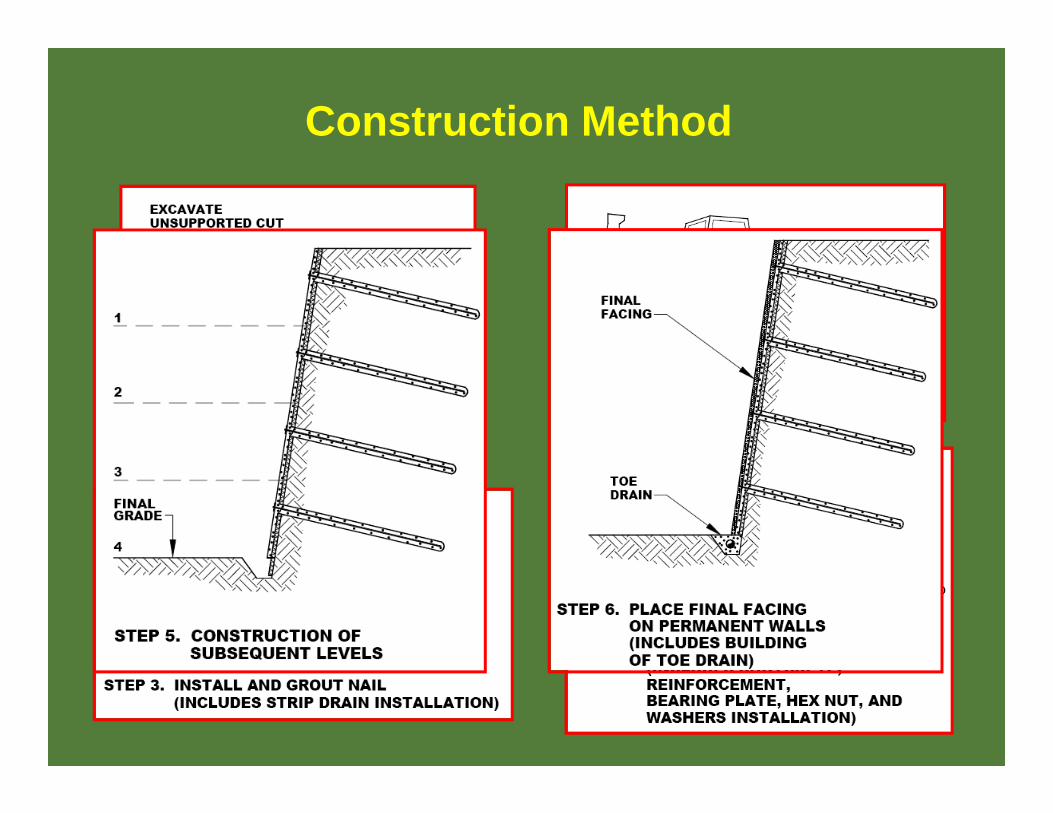
Construction Method

Applications
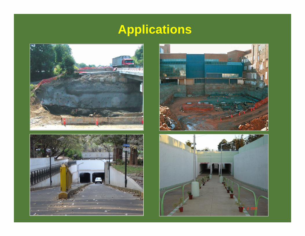
Applications

Small and Large Scale Field Studies
Stocker et al. (1979) Shen et al. (1981a, b) Shen et al. (1982) Gassler and Gudehus (1981) Gassler (1988) Juran (1985) Kitamura et al. (1988) Plumelle et al. (1990) Plumelle and Schlosser (1990)
Kakurai and Hori (1990) Stocker and Riedinger
(1990) Nanda (1995) Kim et al. (1995) Kim et al. (1996) Yamamota et al. (2001) Morgan (2002) Menkiti and Long (2008) Li et al. (2008)
and many more….

Studies on Analyses and Design Aspects
Schlosser (1982)Gassler and Gudehus (1983)Blondeau et al. (1984)Sano et al. (1988)Juran and Chen (1989) Bridle (1989) Jewell and Pedley (1990a, b)Juran et al. (1990a, b)Long et al. (1990)Jewell and Pedley (1990a-b, 1991) Leshchinsky (1990)Schlosser (1991)
Juran et al. (1992a, b)Jewell and Pedley (1992) Kirsten and Dell (1992) Kirsten (1992) Sabahit et al. (1995) Bang et al. (1996) Patra (1998) Bang and Nyaz (2001) Joshi (2003) Sheahan and Ho (2003)Patra and Basudhar (2005)Mittal (2006)
and many more….
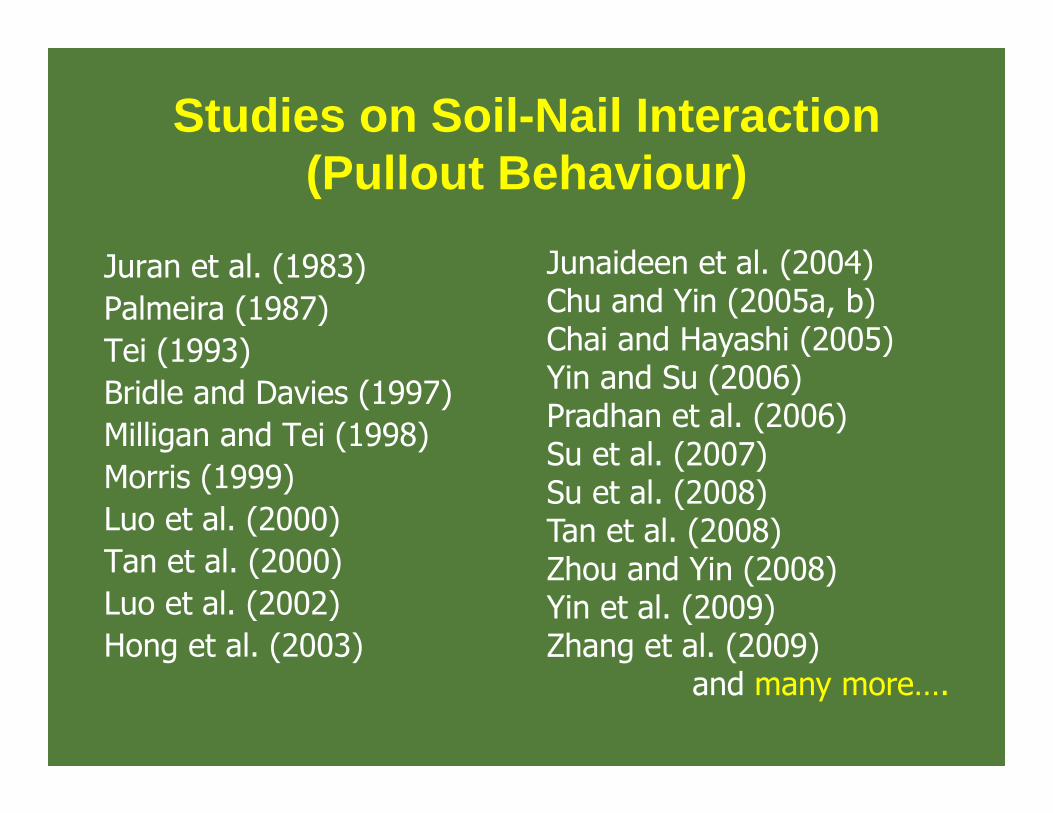
Studies on Soil-Nail Interaction (Pullout Behaviour)
Juran et al. (1983) Palmeira (1987)Tei (1993)Bridle and Davies (1997) Milligan and Tei (1998)Morris (1999)Luo et al. (2000) Tan et al. (2000) Luo et al. (2002)Hong et al. (2003)
Junaideen et al. (2004)Chu and Yin (2005a, b) Chai and Hayashi (2005) Yin and Su (2006) Pradhan et al. (2006) Su et al. (2007) Su et al. (2008) Tan et al. (2008) Zhou and Yin (2008) Yin et al. (2009) Zhang et al. (2009)
and many more….

Studies on Numerical Analyses and Modelling
Sawicki et al. (1988) Lee et al. (1995)Kim et al. (1997)Briaud and Lim (1997) Smith and Su (1997) Zhang et al. (1999)Ng and Lee (2002)Sivakumar Babu et al. (2002)Tan et al. (2005) Cheuk et al. (2005)Fan and Luo (2008)
and few more….
Studies on Seismic Stability and Performance
Sabahit et al. (1996) Tatsuoka et al. (1996) Vucetic et al. (1998) Tufenkjian and Vucetic (2000) Vucetic et al. (2001)Takahashi et al. (2001)Hong et al. (2005)Saran et al. (2005)
and few more….

Studies Based on Reliability Analysis
Yaun et al. (2003)
Studies on Application Case Histories
Tan et al. (1988)Wong et al. (1997)Maric et al. (2001)Murthy et al. (2002)Turner and Jensen (2005)Sivakumar Babu et al. (2007)Yang (2007)
and few more….

Soil Nailing International Codes and Standards
UK Codes and Standards
BS 8006: 1995, BS 8002: 1994, BS 8081: 1989 TRL Report 380 (1993) HA 68/94 (reinforced highway slopes) RT/CE/S/071 (2002) (design of earthworks & earthwork remediations)
Other International Codes and Standards
Eurocode – EC7 Euronorme – prEN 14490 (execution of special geotechnical works – soil
nailing) France – Recommendations Clouterre (1991) USA – FHWA manual for design & construction monitoring of soil
nail walls (1998 and 2003) Scandinavia – Nordic handbook (2002) Hong Kong – Watkins & Powell (1992) and many GEO publications Hong Kong - GEOGUIDE (2008)

Conventional analysis and design Method
Federal Highway Administration (FHWA) has documented comprehensive information on the analysis, design, and construction of soil nail walls in highway engineering applications in its technical manual FHWA (2003) entitled
“Geotechnical Engineering Circular No. 7 – Soil Nail Walls”.
FHWA. (2003). Geotechnical engineering circular No. 7 - soil nail walls. Report FHWA0-IF-03-017, U. S. Department of Transportation, Federal Highway Administration, Washington D. C.
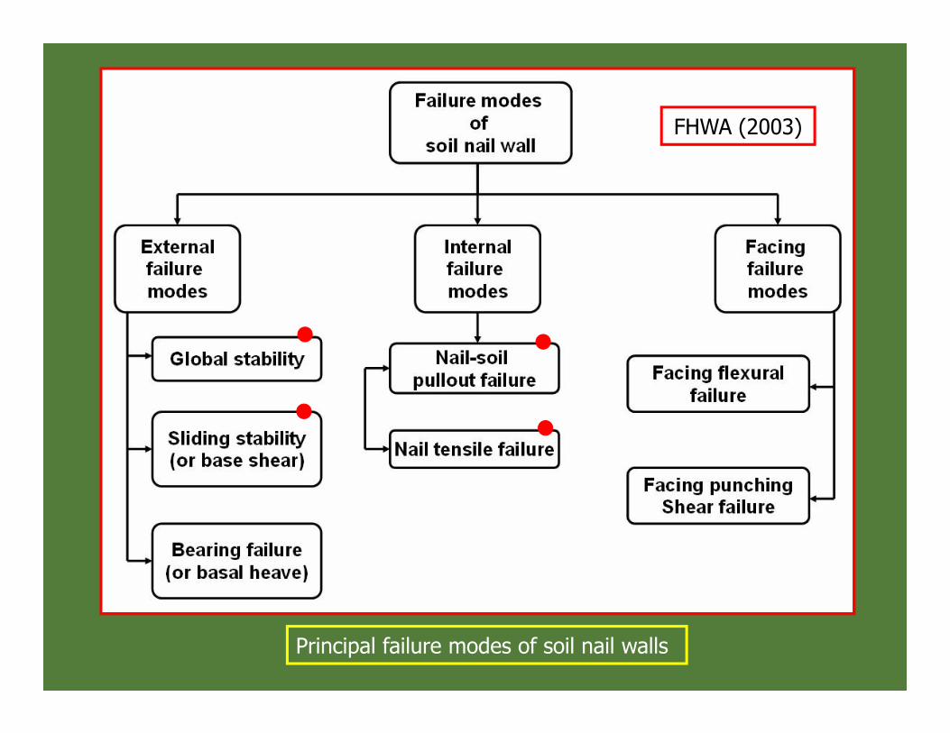
Principal failure modes of soil nail walls
FHWA (2003)

Global Stability Failure
Minimum recommended factor of safety for global stability, FSG
Temporary walls Permanent Walls
Static Seismic Static Seismic
1.35 1.10 1.35 1.10
(Sheahan and Ho 2003; FHWA 2003)
F eq T v eq hG
T v h
cL T cos i W Q F cos T sin i F sin tanRFS
D W Q F sin F cos
45 / 2
n
eq all jj 1h
1T [kN/ m] TS
all T PT min.of R and R
P P uzR kN DL q /1000 2
T yzR kN 0.25 d f /1000
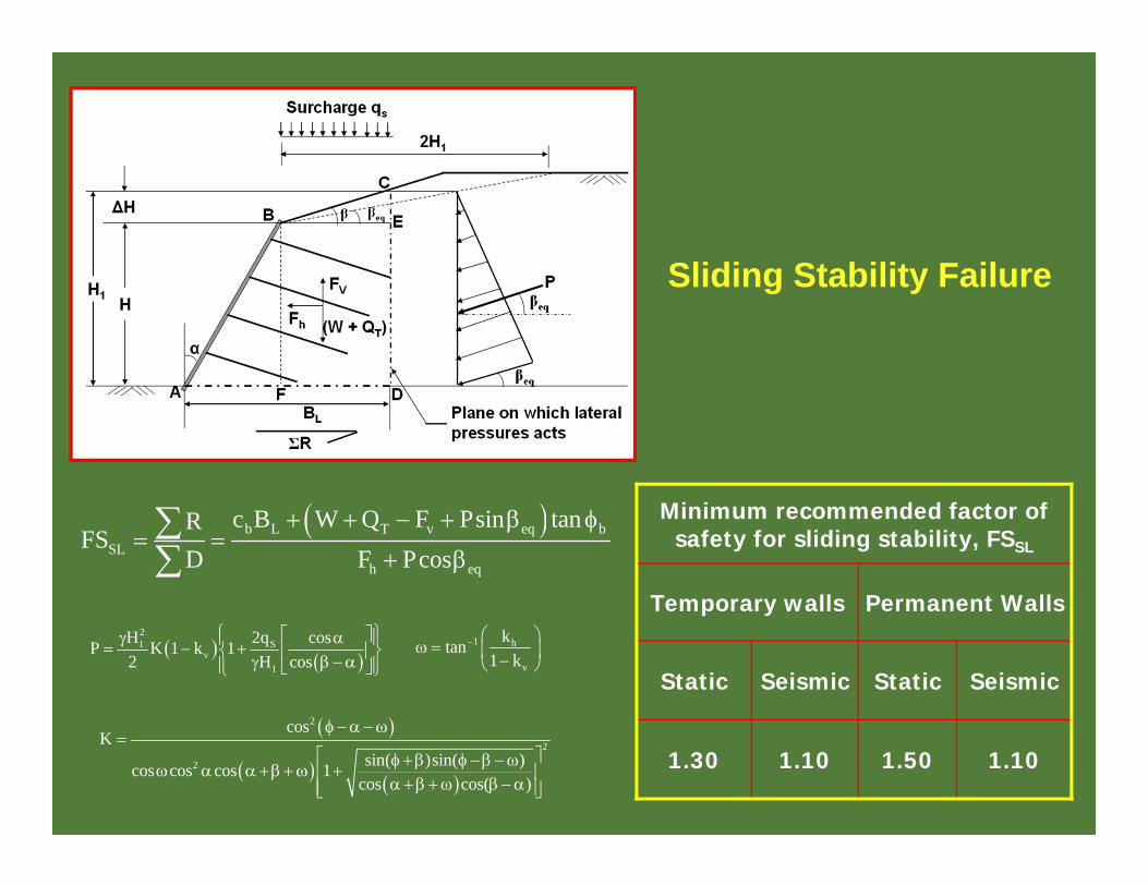
Minimum recommended factor of safety for sliding stability, FSSL
Temporary walls Permanent Walls
Static Seismic Static Seismic
1.30 1.10 1.50 1.10
Sliding Stability Failure
b L T v eq bSL
h eq
c B W Q F Psin tanRFS
D F Pcos
21 S
v1
H 2q cosP K 1 k 12 H cos
2
2
2
cosK
sin( )sin( )cos cos cos 1cos cos( )
1 h
v
ktan1 k

Nail Soil Pullout Failure
Minimum recommended factor of safety for pullout failure, FSP
Temporary walls Permanent Walls
Static Seismic Static Seismic
2.00 1.50 2.00 1.50
P u Pz zP z
max maxz z
R Q LFS
T T
u u DHQ q D
max s H VzT K(q z)S S
P z(H z)cos( )(L ) m L
cos sin( i)

Nail Tensile Strength Failure
T zT z
max z
RFS
T
where: RT = Atfy = maximum axial tensile load capacity of nail
At = c/s area of nail
fy = yield strength of nail
Minimum recommended factor of safety for pullout failure, FST
Temporary walls Permanent Walls
Static Seismic Static Seismic
1.80 1.35 1.80 1.35

Minimum recommended factor of safety (FHWA 2003)
Failure modeStatic loading Seismic loading
Temporary walls
Permanent walls
Both temporary and permanent walls
Facing flexure failure, FSFF 1.35 1.50 1.10
Facing punching shear failure, FSFP
1.35 1.50 1.10
FFFF
o
RFST
FP
FPo
RFST

DESIGN OF 7 m HIGH SOIL NAIL WALL
INITIAL CONSIDERATIONS(a) Vertical height of wall: H = 7 m(b) Face batter: α = 0.0 degrees; Backslope angle: β = 0.0 degrees(c) Nailing type: Driven(d) Soil nail spacing: Sh = Sv = 0.5 m (e) Soil nail inclination: i = 25 degrees(f) Soil nail material: Grade Fe 415; fy = 415 MPa

(g) Soil properties:
Soil type: Dense to very dense sands;
Cohesion: c = 0 kPa;
Friction angle:φ=28o ;
Unit weight: γ=17kN/m3.
Ultimate bond strength (from field pullout test):
(h) Surcharge: qs = 0.0 kPa
[ ] 75.47=02.0×
3=
02.0×=
ππQ
kPaqu
u

PRELIMINARY DESIGNa) Determine maximum axial force Tmax
Maximum axial tensile force Tmax developed is given by
[ ] vhsa ssHγqKkNT )+(=max
36.0=28sin+128sin1
=sin+1sin1
=;φφ
KWhere a
[ ] 71.10=5.0×5.0)7×17+0(36.0=max kNT

(b) Determine minimum nail length L and nail diameter d
Factor of safety of against nail tensile failure
FST = 1.80,
The required cross-sectional area At of the nail
bar can be determined as:2 max T
ty
T FS 10.71 1000 1.80A mm 46.45f 415
Select reinforcement bar of diameter d = 20 mm
providing cross sectional area At = 314 mm2 (>
46.45 mm2).

Minimum length of soil nail L is adopted as the maximum of L1 and L2:
Here: qu = 47.75 kPa; d = 20 mm; T1 = 0.38 kN
v 1 11
u
H S c o s 2 TLs i n i d q
1
7 0.25 cos59 2 0.38L 3.86 msin 59 15 0.02 47.75
L2 = 0.6 x 7 = 4.20 mHence, adopt nail length: L = 4.20 mSummary: Adopt driven soil nails of 20 mm
diameter and 4.20 m length

CHECK FOR IMPORTANT FAILURE MODES
Global Stability:Determination of equivalent nail force Teq
P P u P PR kN dL q 0.02 L 47.75 3L
P
H z c o sL m L
s i n i
2 2
yT
d f 20 415R kN 130.374 1000 4 1000
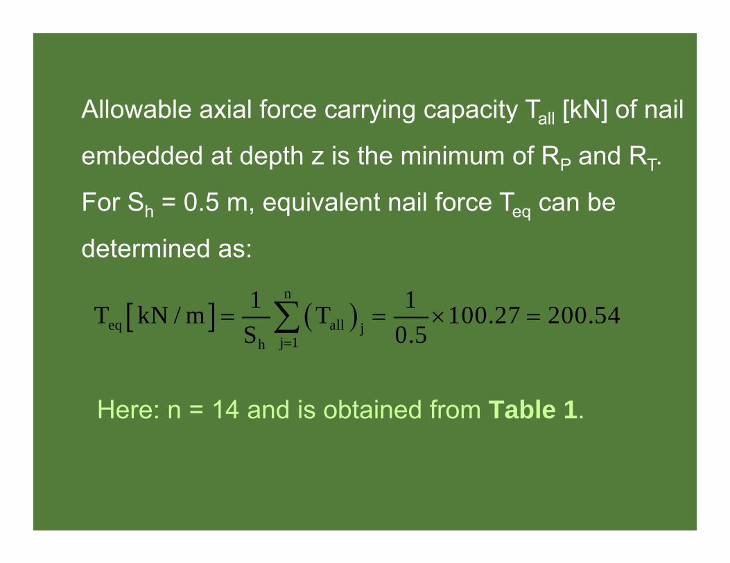
Here: n = 14 and is obtained from Table 1.
n
eq all jj 1h
1 1T kN / m T 100.27 200.54S 0.5
Allowable axial force carrying capacity Tall [kN] of nail
embedded at depth z is the minimum of RP and RT.
For Sh = 0.5 m, equivalent nail force Teq can be
determined as:

Table 1: Allowable axial force carrying capacity of nails at different levels
Nail No. j (from top)
Depth of nail z [m]
Effective pullout
length Lp[m]
Nail pullout capacity RP
[kN]
Nail tensile capacity RT
[kN]
Allowable axial force carrying capacity of
nail Tall [kN]1 0.25 0.7 2.11 130.37 2.112 0.75 0.96 2.89 130.37 2.893 1.25 1.22 3.66 130.37 3.664 1.75 1.48 4.43 130.37 4.435 2.25 1.74 5.21 130.37 5.216 2.75 2.00 5.99 130.37 5.997 3.25 2.26 6.77 130.37 6.778 3.75 2.51 7.54 130.37 7.549 4.25 2.77 8.32 130.37 8.3210 4.75 3.03 9.10 130.37 9.1011 5.25 3.29 9.88 130.37 9.8812 5.75 3.55 10.66 130.37 10.6613 6.25 3.81 11.43 130.37 11.4314 6.75 4.07 12.21 130.37 12.21
100.27 1 4
a l l jj 1
T

Determination of weight of failure wedge W
Weight of failure wedge can be determined as:
Global stability safety factor FSG under static conditions is given by
2W kN/m 0.5 H cot
2W kN/m 0.5 17 7 cot59 250.26
eq T eqG
T
T cos i W Q cos T sin i tanFS
W Q sin
G
200.54cos 59 25 250.26 cos59 200.54sin 59 25 tan28FS 1.37
250.26 sin59

Sliding stabilityFactor of safety for sliding stability of soil nail wall FSSL in static condition is given by:
For static case total active lateral earth pressure PA can be determined as:
b L T A bSL
A
c B W Q P sin tanFS
P cos
2
2A a
1 0.36 17 7P kN/m K H 149.942 2
W [kN/m] = Unit weight x Area of sliding wedge =17 x (7 x 4.2) = 499.8QT [kN/m] = Surcharge load x Length AD = qs x BL = 0 x 4.2 = 0

Soil nail pullout failure
For any particular nail embedded at depth z, factor of safety against pullout failure FSP can be obtained as:
SL
0 4.2 499.8 149.94sin0 tan28FS 1.77
149.94cos0
PP z
z
R( F S )T
T kN 0.36 (0 17 6.75) 0.5 0.5 10.33
P z 6.7512.21(FS ) 1.1810.33

Soil nail tensile strength failure
Factor of safety against nail tensile strength failure
FST for any nail embedded at depth z can be
obtained as: T
T zz
RFST
2 2
yT
d f 20 415R kN 130.374 1000 4 1000
T z 6 .75130 .37( F S ) 12 .5910 .33

Table 2: FSP and FST of soil nails.
Nail No. j (from top)
Depth of nail z [m]
Factor of safety against pullout
failure FSP
Factor of safety against nail tensile strength failure FST
1 0.25 5.51 Very high2 0.75 2.51 Very high3 1.25 1.91 Very high4 1.75 1.66 Very high5 2.25 1.51 Very high6 2.75 1.42 Very high7 3.25 1.36 Very high8 3.75 1.31 Very high9 4.25 1.28 Very high
10 4.75 1.25 Very high11 5.25 1.23 Very high12 5.75 1.21 Very high13 6.25 1.19 13.614 6.75 1.18 12.59

SHOTCRETE (TEMPORARY) FACING DESIGN AND CHECKS
Step 1: Calculate design nail head tensile force at the face ToFor Tmax = 10.71 kN; and Smax =0.5 m, nail head tensile force at the wall face To can be obtained as:
Step 2: Adopt wall facing thicknessTemporary facing thickness h: 50 mm
o max maxT kN T 0.6 0.2(S 1) 10.710.6 0.2(0.5 1) 5.35

Step 3: Adopt appropriate facing materials
(a) Steel reinforcement: Grade Fe 415 with
characteristic strength: fy = 415 MPa
(b) Concrete/shotcrete: Grade M20 with
characteristic compressive strength: fck = 20
MPa
(c) Welded wire mesh (temporary facing): WMM
102 x 102–MW19 x MW19.

(d) Horizontal and vertical waler bars (temporary
facing): 2 x 10 mm diameter, (fy = 415 MPa, Avw
= Ahw = 2 x 78 = 156 mm2) in both directions.
(e) Bearing plate (temporary facing): Grade 250 (fy=250 MPa); Shape: Square; Length: LBP = 225
mm; Thickness: tp = 25 mm

Step 4: Checks for facing reinforcementDetermine the minimum and the maximum reinforcement ratios as:
In addition the ratio of the reinforcement in thenail head and mid-span zones should be lessthan 2.5 to ensure comparable ratio of flexuralcapacities in theses areas.
ckmin
y
f MPa 20% 20 20 0.21f MPa 415
ckmax
y y
f MPa 600 20 600% 50 50 1.42f MPa 600 f MPa 415 600 415

Step 5: Verify facing flexural resistance RFF
Calculate facing flexural resistance RFF as:
Safety factor against facing flexural failure FSFFis given by
2F hFF vn vm y
v
C SR kN a a mm / m h m f MPa265 S
FF2R kN 472.4 1 0.05 415 74
265
F FF F
o
R 7 4F S 1 3 .8 3T 5 .3 5
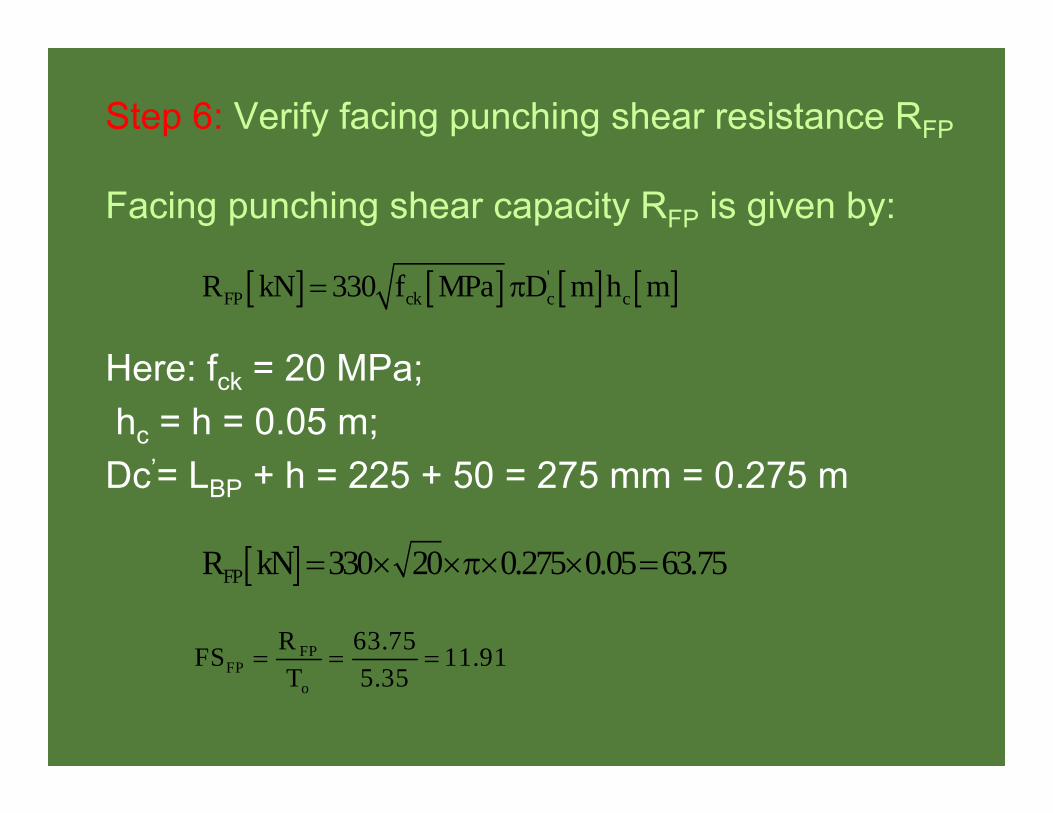
Step 6: Verify facing punching shear resistance RFP
Facing punching shear capacity RFP is given by:
Here: fck = 20 MPa;hc = h = 0.05 m; Dc’= LBP + h = 225 + 50 = 275 mm = 0.275 m
'FP ck c cR kN 330 f MPa D m h m
FPR kN 330 20 0.275 0.05 63.75
FPFP
o
R 63.75FS 11.91T 5.35

Table 3: Summary of factors of safety for various failure modes
Failure mode Remarks Factor of safetyGlobal FSG -- 1.37
Sliding FSSL -- 1.77
Pull-out resistance FSP Minimum
1.18 (increases to 3 if grouted nails (30 kN/m) at 1m spacing are used.
Nail bar tensile strength FST Minimum 12.59
Facing flexure FSFF Temporary facing 13.83Facing punching FSFP Temporary facing 11.91

Table 4: Summary of temporary facing design (All dimensions are in mm)
Element Description Temporary facing
GeneralThickness h 50Facing type Shotcrete
Concrete grade M20
ReinforcementType Welded wire mesh (WWM)
Steel grade Fe415Denomination 102 x 102 – MW19 x MW19
Other reinforcement Type Waler bars 2 - 10 b/w
Bearing plateType SquareSteel Fe250
Dimensions 225 x 225 x 25

Typical Example of Soil Nail Wall Simulation
E1E2
E3
E4E5
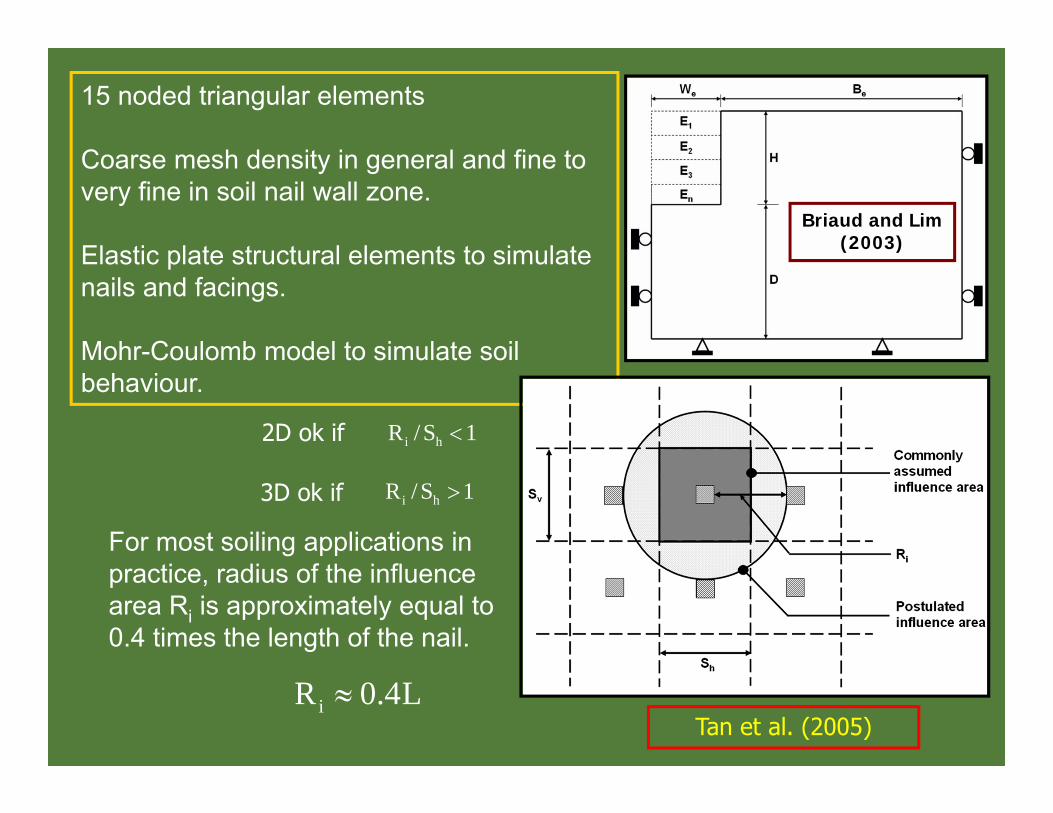
Briaud and Lim (2003)
Tan et al. (2005)
i hR /S 12D ok if
i hR /S 13D ok if
For most soiling applications in practice, radius of the influence area Ri is approximately equal to 0.4 times the length of the nail.
iR 0.4L
15 noded triangular elements
Coarse mesh density in general and fine to very fine in soil nail wall zone.
Elastic plate structural elements to simulate nails and facings.
Mohr-Coulomb model to simulate soil behaviour.

For example:
Wang and Richwein 2002
Junaideen et al. 2004
Pradhan et al. 2006
Gosavi et al. 2008

In this method the strength parameters 'tan φ’and 'cohesion c' of the soil are successively and simultaneously reduced until failure of the structure occurs (equation 1).
The parameters with the subscript 'input' refer to the input properties and parameters with the subscript 'reduced' refer to the reduced properties used in the analysis. This ratio is set to 1.0 at the start of a calculation to set all material strengths to their actual values. These values with subscript 'reduced' are successively reduced until failure of the structure occurs. At this point the factor of safety is given by equation 2.
input input
reduced reduced
tan c1.0
tan c
available strengthFSstrength at failure
…(1.)
…(2.)
Strength Reduction Technique

Simulated wall
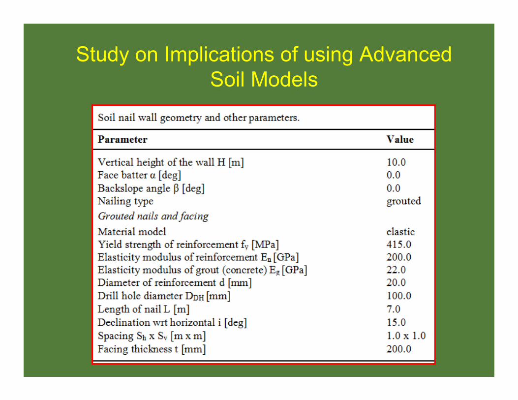
Study on Implications of using Advanced Soil Models

MC – Mohr Coulomb modelHS – Hardening soil model (Schanz et al. 1999)HSsmall – Hardening soil with small strain stiffness (Benz 2007)
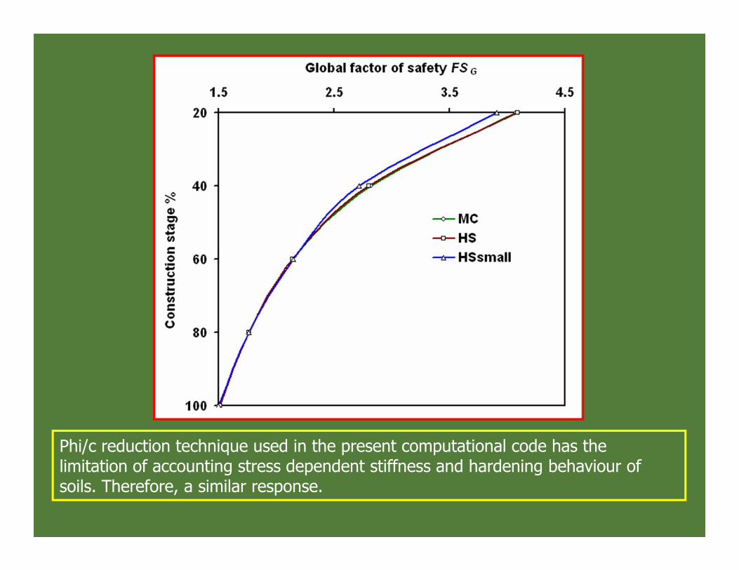
Phi/c reduction technique used in the present computational code has the limitation of accounting stress dependent stiffness and hardening behaviour of soils. Therefore, a similar response.

MC-model over-estimates the base heave (Brinkgreve et al. 2006; Callisto et al. 1999).
May be attributed to the consideration of linear elastic pre-failure soil behavior assumed in MC-model formulation.
Advanced soil models shall be preferred in soft soil conditions.
This aspect may be useful from the consideration of stability of soil nail walls during construction stages.
HSsmall model predicts excavation heave even lesser than HS-model attributing to the role of increased stiffness of soils at small strains (Brinkgreve 2006; Benz 2007)

Upto 60% CS, MC > HS and HSsmall. Beyond 60% CS, HS > HSsmall > MC.
Possibly due to a hyperbolic stress-strain relationship with control of stress leveldependency of soil stiffness in advanced models.
Unlike, advanced models, MC model has fixed yield surface in the principal stressspace, which do not account for plastic straining due to the increasing constructionstages.
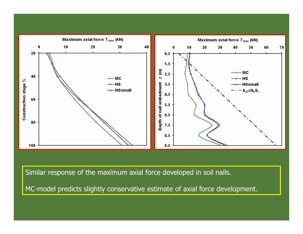
Similar response of the maximum axial force developed in soil nails.
MC-model predicts slightly conservative estimate of axial force development.

Implications of Consideration of Bending Stiffness of Soil Nails
Trend of global factor of safety of soil nail wall with construction stage
Plate structural element can be used to perform analysis of soil nail walls considering bending stiffness of soil nails as they require both axial stiffness EA and bending stiffness EI as the main material parameters.
Geogrid structural elements can be used to model soil nails with considering bending stiffness of soil nails as they require only axial stiffness EA as the main input parameter
Using MC soil model

The bending and shear capacities of soil nail start mobilising with increasing construction stages.
Almost same lateral displacements observed.

Tmax in nails simulated using geogrid elements is found to be 15% more than plate.
Very similar response
Soil nail walls reported to have performed remarkably well during high intensity earthquakes (Felio et al. 1990; Vucetic et al. 1998; Tatsuoka et al. 1997; Tufenkjian 2000).
In order to study the performance of soil nail walls in seismic conditions, a typical soil nail wall of 8 m height is conventionally designed using allowable stress design approach presented in FHWA (2003).
Conventionally designed soil nail wall is then simulated under static and seismic (pseudo-static and time history data) conditions.
Seismic Analysis Soil Nail Walls


Ground acceleration time histories for three earthquakes

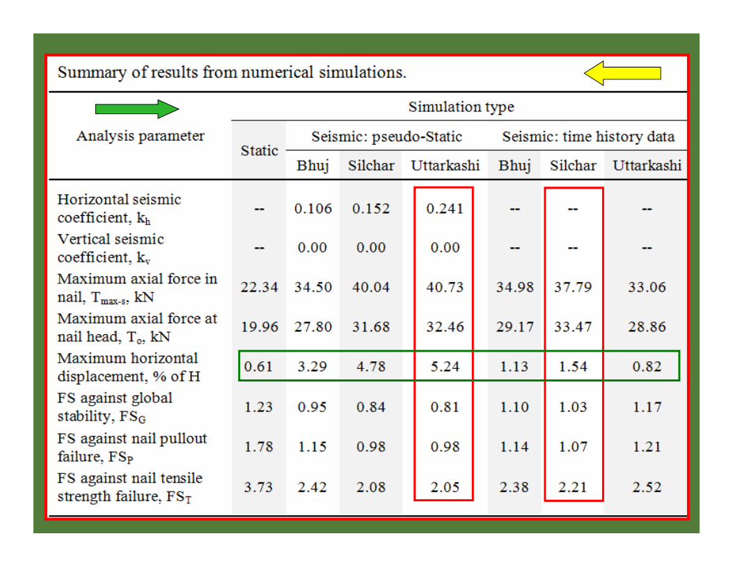

In general a very similar response
Upper nails (top two or three): more for the pseudo-static
Lower nails: very close for both pseudo-static and time history data

In general a very similar response
Very conservative for the pseudo-static
Tolerable seismically induced displacement corresponds to 0.63-1.25% of H (FHWA 2003)

Original L = 4.70 m
Conclusions Conventional design procedure using FHWA (2003) provides a safe but
conservative design.
Provision of facing results in the significant improvement of the stability and performance of soil nail walls.
Intermittent facing with a small offset in each construction stage is found to be more effective in reducing the lateral deformation of soil nail walls than regular continuous vertical facing.
For soil nail walls with rigid facing the axial force developed at the head (i.e. at facing end) of a given soil nail is generally 80-90% of the maximum axial force developed in it.
In addition to the peak seismic acceleration, the overall stability (i.e. external as well as internal) and performance of the soil nail walls is dependant on the other spectral properties (e.g., strong motion duration and peak displacement) of the time history data of an earthquake.
Pseudo-static analyses is found to provide conservative estimate of displacements and factor of safety values.
