kwp type series booklet · kwp main applications pump for handling pre-treated sewage, waste water,...
TRANSCRIPT

Dry-installed Volute Casing Pump
KWP
Type Series Booklet

Legal information/Copyright
Type Series Booklet KWP
All rights reserved. The contents provided herein must neither be distributed, copied, reproduced,edited or processed for any other purpose, nor otherwise transmitted, published or made available toa third party without the manufacturer's express written consent.
Subject to technical modification without prior notice.
© KSB Aktiengesellschaft, Frankenthal 18.09.2014
Contents
Centrifugal Pumps with Shaft Seal ...................................................................................................................4
Dry-installed Volute Casing Pump ................................................................................................................................. 4
KWP ............................................................................................................................................................................ 4
Main applications ................................................................................................................................................ 4
Operating data ....................................................................................................................................................4
Designation .......................................................................................................................................................... 4
Design details ....................................................................................................................................................... 4
Sizes ...................................................................................................................................................................... 7
Automation .......................................................................................................................................................... 7
Material code ....................................................................................................................................................... 7
Material variants .................................................................................................................................................. 9
Technical data .................................................................................................................................................... 10
Selection charts ................................................................................................................................................. 13
Dimensions and connections ............................................................................................................................16
Coating and preservation .................................................................................................................................27
Product benefits ................................................................................................................................................27
Acceptance tests / Warranties ........................................................................................................................... 27
General assembly drawings with list of components ...................................................................................... 28
Detailed designation .........................................................................................................................................38
Contents
3
Centrifugal Pumps with Shaft Seal
Dry-installed Volute Casing Pump
KWP
Main applications
Pump for handling pre-treated sewage, waste water, all typesof slurries without stringy material and pulps up to 5 % bonedry with a maximum density of 2000 kg/m³.
▪ Paper and cellulose industry
▪ Sugar industry
▪ Food and beverages industry
▪ Fossil-fuelled power stations
▪ Chemical industry
▪ Petrochemical industry
▪ Flue gas desulphurisation
▪ Coal upgrading plants
▪ Industrial effluent treatment systems
▪ Seawater desalination/reverse osmosis
Operating data
Operating properties
Characteristic ValueNominal discharge nozzlediameter
DN [mm] 40 - 900
Flow rate Q [m3/h] ≤ 15,0001)
Head H [m] ≤ 1001)
Operating temperature T [°C] -40 to +1401)
Operating pressure p [bar] ≤ 101)
Designation
Example: KWPK125-100-0250 GDNG10
Key to the designation
Code DescriptionKWP Type seriesK Impeller type
K Channel impellerO Open multi-channel impellerF Free-flow impeller
125 Nominal suction nozzle diameter [mm]100 Nominal discharge nozzle diameter [mm]250 Nominal impeller diameter [mm]GDNG Material code (⇨ Page 7)10 Design variant
Further information on the designation
(⇨ Page 38)
Design details
Design
▪ Volute casing pump
▪ Back pull-out design
▪ Horizontal installation
▪ Single-stage
▪ Single-entry
Pump casing
▪ Radially split volute casing
▪ Volute casing with integrally cast pump feet
▪ Pump casing fitted with a wear plate
▪ Discharge cover available in the following versions:
1) Higher values on request
Centrifugal Pumps with Shaft SealDry-installed Volute Casing Pump
4 KWP

D00481
D00476
D00475
1
3
2
Discharge cover versions
1 Discharge cover withintegrally cast stuffingbox housing (cylindricalcover); material variants:GNNG, GDNG, DDDD
2 Discharge cover withbolted stuffing boxhousing (cylindricalcover, split); materialvariants: GHHH, HHHHand all sizes on bearingbrackets P08sx, P10ax,P12sx for all availablematerials.
3 For mechanical seal:discharge cover withconical seal chamber (A-type cover); materialvariants: GNNG, GDNG,DDDD, DKKM, GHHH,HHHH
Flanges
▪ Suction flange
– Up to DN 350 plus 400-400-500, 600-600-824/-825 and700-700-923/-929: tapped blind hole 1.25 × d, matingdimensions to DIN 2501, PN10 /16 (DN 40 - DN 150),PN10 (DN 200 - DN 350)
– From DN 400 plus 350-350-500: through-holes toEN 1092-2, PN10
▪ Discharge flange
– DN 40 to DN 150: through-holes to EN 1092-2,PN10/16
– DN 200 and above: through-holes to EN 1092-2, PN10
– Tapped through-holes DIN 2501, PN10 for600-600-824/-825, 700-700-923/-929, 700-700-953/-959,800-800-934/-935/-939, 800-900-883,900-900-1133/-1134/-1138/-1139
Suction side versions
▪ Wear plate
– 065-040-250 to 600-600-669
▪ Casing wear ring
– 250-250-315
– 300-300-400
– 350-350-400
– 400-400-500
▪ Suction cover from 400-400-533
Impeller type
▪ Back vanes reduce axial thrust.
▪ Various, application-based impeller types
Centrifugal Pumps with Shaft SealDry-installed Volute Casing Pump
KWP 5
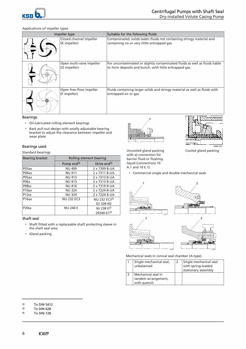
Applications of impeller types
Impeller type Suitable for the following fluidsClosed channel impeller (K impeller)
Contaminated, solids-laden fluids not containing stringy material andcontaining no or very little entrapped gas
Open multi-vane impeller(O impeller)
For uncontaminated or slightly contaminated fluids as well as fluids liableto form deposits and bunch, with little entrapped gas.
Open free-flow impeller (F impeller)
Fluids containing larger solids and stringy material as well as fluids withentrapped air or gas
Bearings
▪ Oil-lubricated rolling element bearings
▪ Back pull-out design with axially adjustable bearingbracket to adjust the clearance between impeller andwear plate
Bearings used
Standard bearings
Bearing bracket Rolling element bearing
Pump end2) Drive end3)
P03ax NU 409 2 x 7309 B-UAP04ax NU 411 2 x 7311 B-UAP05ax NU 413 2 x 7313 B-UAP06x NU 413 2 x 7313 B-UAP08sx NU 416 2 x 7319 B-UAP10ax NU 324 2 x 7224 B-UAP12sx NU 324 2 x 7224 B-UAP16ax NU 232 EC3 NU 232 EC32)
QJ 328-N2P20sx NU 240 E NJ 238 E2)
29340-E14)
Shaft seal
▪ Shaft fitted with a replaceable shaft protecting sleeve inthe shaft seal area
▪ Gland packing
a
Uncooled gland packingwith a) connection forbarrier fluid or flushingliquid (connections 10A.1 and 10 E.1)
Cooled gland packing
▪ Commercial single and double mechanical seals
D00477
D00479 D00478
1 2
2 3
Mechanical seals in conical seal chamber (A-type)
1 Single mechanical seal,unbalanced
2 Single mechanical sealwith spring-loadedstationary assembly
3 Mechanical seal intandem arrangement,with quench
2) To DIN 54123) To DIN 6284) To DIN 728
Centrifugal Pumps with Shaft SealDry-installed Volute Casing Pump
6 KWP

1 2
Mechanical seals in conical seal chamber (A-type)
1 Single mechanical seal, balanced, with spring-loadedstationary assembly, bi-directional, for P16ax/P20sxV10
2 Single mechanical seal, with spring-loaded stationaryassembly, balanced, bi-directional, for P20sx V11
Drive
▪ Electric motor connected to the pump via a coupling orbelt drive.
Sizes
Size combinations
Dis
char
ge
no
zzle
Nominal impeller diameter
201 200 251 250253
311 313315320
400403
500501503504505
533583
544 630633634635637
710713
663669710753
803813814
824825873923
923929953959
934935939
8831133113411381139
Impeller type
F K O F K O F K O K O K O K K K K K K K K K K040 - - - - ✘ - - ✘ - - - - - - - - - - - - - - -050 ✘ ✘ ✘ - - - - - - ✘ - - - - - - - - - - - - -065 ✘ ✘ ✘ - - - - ✘ ✘ ✘ - - - - - - - - - - - - -080 - - - ✘ ✘ ✘ ✘ ✘ - ✘ ✘ ✘ - - - - - - - - - - -100 - - - ✘ ✘ ✘ - ✘ - ✘ ✘ - - - - - - - - - - - -125 - - - - - - - - - - - ✘ - - - - - - - - - - -150 - - - - - - ✘ ✘ ✘ ✘ - - - - - - - - - - - - -200 - - - - - - - ✘ - ✘ ✘ ✘ - - - - - - - - - - -250 - - - - - - - ✘ - ✘ - ✘ ✘ - - ✘ - - - - - - -300 - - - - - - - - - ✘ - ✘ - - - - - - - - - - -350 - - - - - - - - - ✘ - ✘ - - - ✘ - - - - - - -400 - - - - - - - - - - - ✘ - ✘ - - ✘ - - - - - -500 - - - - - - - - - - - - - - ✘ ✘ - - - - - - -600 - - - - - - - - - - - - - - - - - ✘ ✘ ✘ - - -700 - - - - - - - - - - - - - - - - - - - - ✘ - -800 - - - - - - - - - - - - - - - - - - - - - ✘ -900 - - - - - - - - - - - - - - - - - - - - - - ✘
Automation
Automation options:
▪ Hyamaster
▪ hyatronic
▪ PumpDrive
Material code
Example of material code: DMKM
Key to material code
Code DescriptionD Casing material
G GJL-250D NORIDUR 1.4593H NORIHARD NH 15 3K GJS-400-18-LT/ CeramikPolySiC5)
M Impeller material
5) ≥ 600-600-0824
Centrifugal Pumps with Shaft SealDry-installed Volute Casing Pump
KWP 7
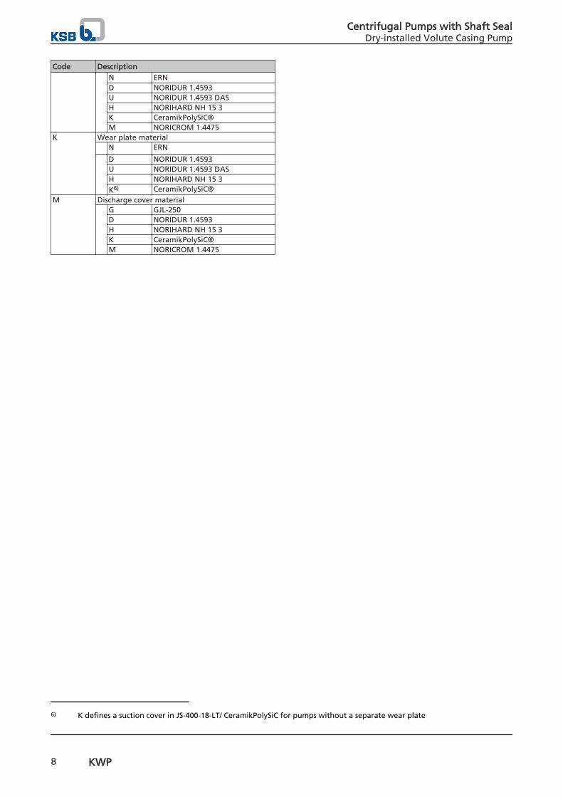
Code Description
N ERND NORIDUR 1.4593U NORIDUR 1.4593 DASH NORIHARD NH 15 3K CeramikPolySiC®M NORICROM 1.4475
K Wear plate material N ERN
D NORIDUR 1.4593U NORIDUR 1.4593 DASH NORIHARD NH 15 3K6) CeramikPolySiC®
M Discharge cover material G GJL-250
D NORIDUR 1.4593H NORIHARD NH 15 3K CeramikPolySiC®M NORICROM 1.4475
6) K defines a suction cover in JS-400-18-LT/ CeramikPolySiC for pumps without a separate wear plate
Centrifugal Pumps with Shaft SealDry-installed Volute Casing Pump
8 KWP
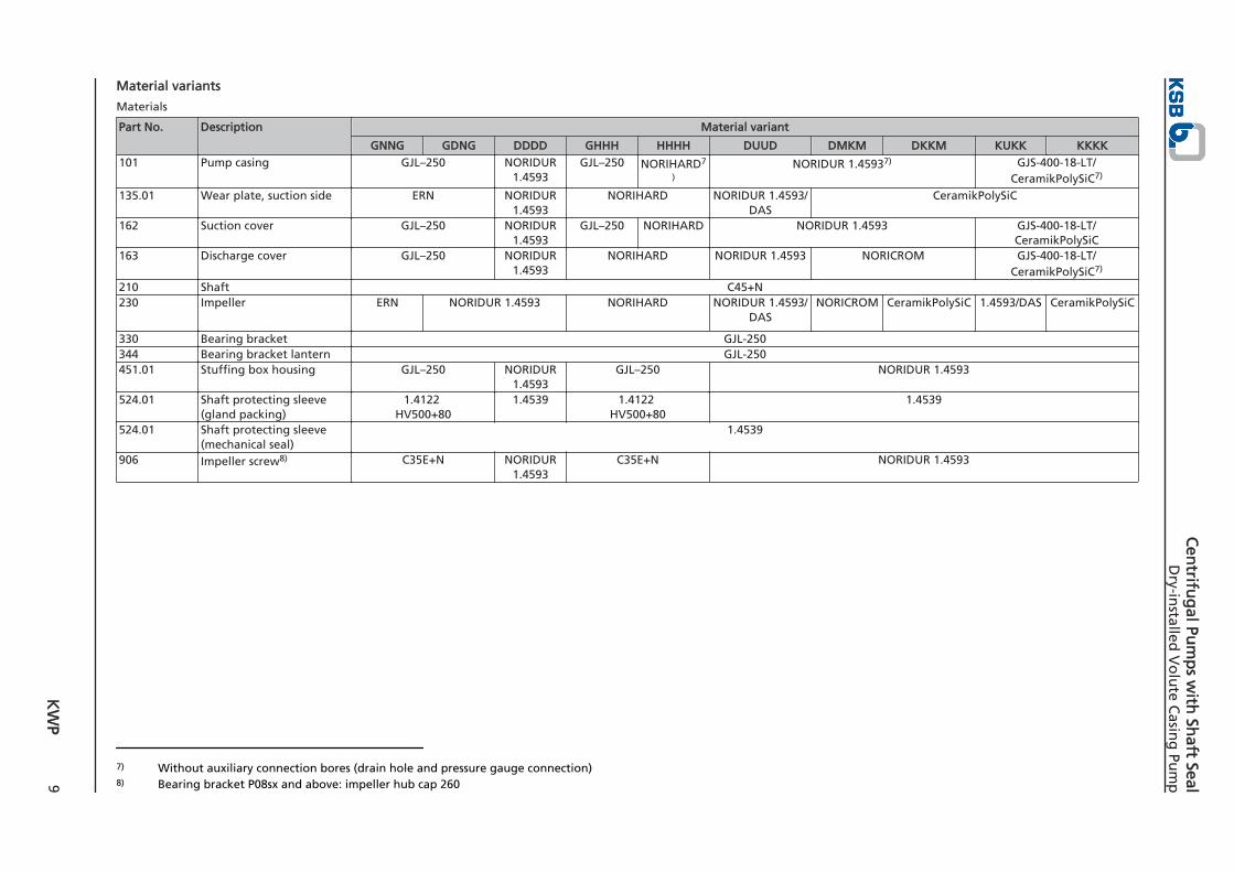
Material variants
Materials
Part No. Description Material variant
GNNG GDNG DDDD GHHH HHHH DUUD DMKM DKKM KUKK KKKK101 Pump casing GJL–250 NORIDUR
1.4593GJL–250 NORIHARD7
)NORIDUR 1.45937) GJS-400-18-LT/
CeramikPolySiC7)
135.01 Wear plate, suction side ERN NORIDUR1.4593
NORIHARD NORIDUR 1.4593/DAS
CeramikPolySiC
162 Suction cover GJL–250 NORIDUR1.4593
GJL–250 NORIHARD NORIDUR 1.4593 GJS-400-18-LT/CeramikPolySiC
163 Discharge cover GJL–250 NORIDUR1.4593
NORIHARD NORIDUR 1.4593 NORICROM GJS-400-18-LT/CeramikPolySiC7)
210 Shaft C45+N230 Impeller ERN NORIDUR 1.4593 NORIHARD NORIDUR 1.4593/
DASNORICROM CeramikPolySiC 1.4593/DAS CeramikPolySiC
330 Bearing bracket GJL-250344 Bearing bracket lantern GJL-250451.01 Stuffing box housing GJL–250 NORIDUR
1.4593GJL–250 NORIDUR 1.4593
524.01 Shaft protecting sleeve(gland packing)
1.4122 HV500+80
1.4539 1.4122 HV500+80
1.4539
524.01 Shaft protecting sleeve(mechanical seal)
1.4539
906 Impeller screw8) C35E+N NORIDUR1.4593
C35E+N NORIDUR 1.4593
7) Without auxiliary connection bores (drain hole and pressure gauge connection)8) Bearing bracket P08sx and above: impeller hub cap 260
K
WP
9
Cen
trifug
al Pum
ps w
ith Sh
aft SealD
ry-installed
Vo
lute C
asing
Pum
p
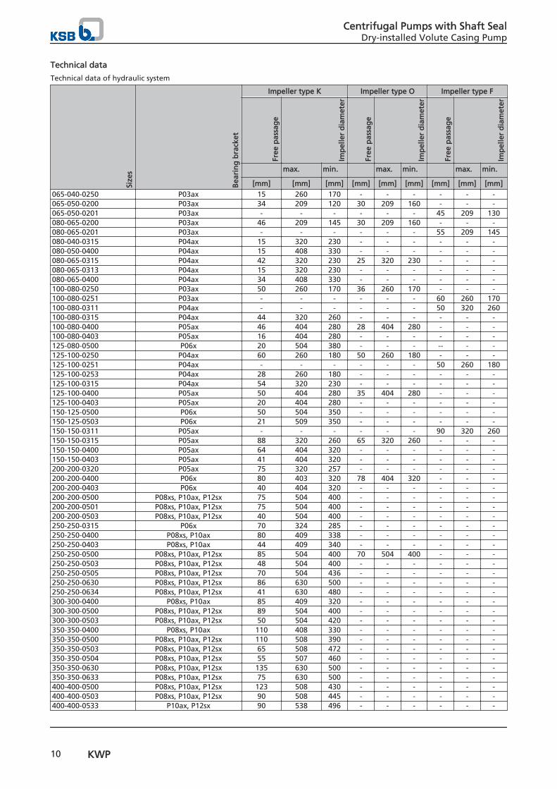
Technical data
Technical data of hydraulic system
Size
s
Bea
rin
g b
rack
et
Impeller type K Impeller type O Impeller type F
Free
pas
sag
e
Imp
elle
r d
iam
eter
Free
pas
sag
e
Imp
elle
r d
iam
eter
Free
pas
sag
e
Imp
elle
r d
iam
eter
max. min. max. min. max. min.
[mm] [mm] [mm] [mm] [mm] [mm] [mm] [mm] [mm]065-040-0250 P03ax 15 260 170 - - - - - -065-050-0200 P03ax 34 209 120 30 209 160 - - -065-050-0201 P03ax - - - - - - 45 209 130080-065-0200 P03ax 46 209 145 30 209 160 - - -080-065-0201 P03ax - - - - - - 55 209 145080-040-0315 P04ax 15 320 230 - - - - - -080-050-0400 P04ax 15 408 330 - - - - - -080-065-0315 P04ax 42 320 230 25 320 230 - - -080-065-0313 P04ax 15 320 230 - - - - - -080-065-0400 P04ax 34 408 330 - - - - - -100-080-0250 P03ax 50 260 170 36 260 170 - - -100-080-0251 P03ax - - - - - - 60 260 170100-080-0311 P04ax - - - - - - 50 320 260100-080-0315 P04ax 44 320 260 - - - - - -100-080-0400 P05ax 46 404 280 28 404 280 - - -100-080-0403 P05ax 16 404 280 - - - - - -125-080-0500 P06x 20 504 380 - - - -- - -125-100-0250 P04ax 60 260 180 50 260 180 - - -125-100-0251 P04ax - - - - - - 50 260 180125-100-0253 P04ax 28 260 180 - - - - - -125-100-0315 P04ax 54 320 230 - - - - - -125-100-0400 P05ax 50 404 280 35 404 280 - - -125-100-0403 P05ax 20 404 280 - - - - - -150-125-0500 P06x 50 504 350 - - - - - -150-125-0503 P06x 21 509 350 - - - - - -150-150-0311 P05ax - - - - - - 90 320 260150-150-0315 P05ax 88 320 260 65 320 260 - - -150-150-0400 P05ax 64 404 320 - - - - - -150-150-0403 P05ax 41 404 320 - - - - - -200-200-0320 P05ax 75 320 257 - - - - - -200-200-0400 P06x 80 403 320 78 404 320 - - -200-200-0403 P06x 40 404 320 - - - - - -200-200-0500 P08xs, P10ax, P12sx 75 504 400 - - - - - -200-200-0501 P08xs, P10ax, P12sx 75 504 400 - - - - - -200-200-0503 P08xs, P10ax, P12sx 40 504 400 - - - - - -250-250-0315 P06x 70 324 285 - - - - - -250-250-0400 P08xs, P10ax 80 409 338 - - - - - -250-250-0403 P08xs, P10ax 44 409 340 - - - - - -250-250-0500 P08xs, P10ax, P12sx 85 504 400 70 504 400 - - -250-250-0503 P08xs, P10ax, P12sx 48 504 400 - - - - - -250-250-0505 P08xs, P10ax, P12sx 70 504 436 - - - - - -250-250-0630 P08xs, P10ax, P12sx 86 630 500 - - - - - -250-250-0634 P08xs, P10ax, P12sx 41 630 480 - - - - - -300-300-0400 P08xs, P10ax 85 409 320 - - - - - -300-300-0500 P08xs, P10ax, P12sx 89 504 400 - - - - - -300-300-0503 P08xs, P10ax, P12sx 50 504 420 - - - - - -350-350-0400 P08xs, P10ax 110 408 330 - - - - - -350-350-0500 P08xs, P10ax, P12sx 110 508 390 - - - - - -350-350-0503 P08xs, P10ax, P12sx 65 508 472 - - - - - -350-350-0504 P08xs, P10ax, P12sx 55 507 460 - - - - - -350-350-0630 P08xs, P10ax, P12sx 135 630 500 - - - - - -350-350-0633 P08xs, P10ax, P12sx 75 630 500 - - - - - -400-400-0500 P08xs, P10ax, P12sx 123 508 430 - - - - - -400-400-0503 P08xs, P10ax, P12sx 90 508 445 - - - - - -400-400-0533 P10ax, P12sx 90 538 496 - - - - - -
Centrifugal Pumps with Shaft SealDry-installed Volute Casing Pump
10 KWP

Size
s
Bea
rin
g b
rack
et
Impeller type K Impeller type O Impeller type F
Free
pas
sag
e
Imp
elle
r d
iam
eter
Free
pas
sag
e
Imp
elle
r d
iam
eter
Free
pas
sag
e
Imp
elle
r d
iam
eter
max. min. max. min. max. min.
[mm] [mm] [mm] [mm] [mm] [mm] [mm] [mm] [mm]400-400-0583 P10ax, P12sx 90 600 550 - - - - - -500-400-0710 P10ax, P12sx, P16ax 160 730 630 - - - - - -500-400-0713 P10ax, P12sx, P16ax 65 730 630 - - - - - -500-500-0544 P10ax, P12sx 75 572 495 - - - - - -500-500-0630 P10ax, P12sx, P16ax 142 636 528 - - - - - -500-500-0633 P10ax, P12sx, P16ax 90 636 534 - - - - - -500-500-0634 P10ax, P12sx, P16ax 85 636 554 - - - - - -500-500-0635 P10ax, P12sx, P16ax 75 636 565 - - - - - -500-500-0637 P10ax, P12sx, P16ax 85 636 540 - - - - - -600-600-0663 P12sx 80 700 620 - - - - - -600-600-0669 P12sx 80 700 630 - - - - - -600-600-0710 P12sx, P16ax 165 716 650 - - - - - -600-600-0753 P16ax 112 750 675 - - - - - -600-600-0803 P16ax 100 780 718 - - - - - -600-600-0813 P16ax 95 830 710 - - - - - -600-600-0824 P16ax 95 794 720 - - - - - -600-600-0825 P16ax 95 800 709 - - - - - -600-600-0873 P16ax 97 880 800 - - - - - -600-600-0923 P20sx 113 930 840 - - - - - -700-700-0923 P20sx 115 870 765 - - - - - -700-700-0929 P20sx 100 870 780 - - - - - -800-700-0953 P20sx 110 940 834 - - - - - -800-700-0959 P20sx 105 940 820 - - - - - -800-800-0934 P20sx 115 950 845 - - - - - -800-800-0935 P20sx 155 940 850 - - - - - -800-800-0939 P20sx 86 950 854 - - - - - -800-900-0883 P20sx 155 855 750 - - - - - -900-900-1133 P20sx 140 1120 1018 - - - - - -900-900-1134 P20sx 150 1120 1008 - - - - - -900-900-1138 P20sx 120 1122 1006 - - - - - -900-900-1139 P20sx 110 1120 980 - - - - - -
Centrifugal Pumps with Shaft SealDry-installed Volute Casing Pump
KWP 11

Technical data of bearing bracketB
eari
ng
bra
cket
Gland packing Shaft diameter Shaftprotecting
sleeve
Bearings
Bo
re d
iam
eter
Len
gth
Pack
ing
rin
g d
imen
sio
ns
Nu
mb
er o
f p
acki
ng
rin
gs
Wid
th o
f la
nte
rn r
ing
Cle
aran
ce f
or
rem
ovi
ng
th
e g
lan
d p
acki
ng
In s
tuff
ing
bo
x h
ou
sin
g
At
bea
rin
gs
At
cou
plin
g
Gla
nd
pac
kin
g
Mec
han
ical
sea
l
Pum
p e
nd
Dri
ve e
nd
Pum
p e
nd
Dri
ve e
nd
[mm] [mm] [mm] [Qty] [mm] [mm] [mm] [mm] [mm] [mm] [mm] P03ax 65 64 10 x 10 4 20 80 33 45 45 32 45
Dep
end
ing
on
mak
e
NU 409 2 x 7309 B-UAP04ax 75 64 10 x 10 4 20 65 42 55 55 42 55 NU 411 2 x 7311 B-UAP05ax 95 79 12,5 x 12,5 4 25 75 53 65 65 48 70 NU 413 2 x 7313 B-UAP06x 95 79 12,5 x 12,5 4 25 75 65 65 65 60 80 NU 413 2 x 7313 B-UAP08sx 103 132 16 x 16 4 30 105 80 80 95 75 100 NU 416 2 x 7319 B-UAP10ax 103 152 16 x 16 4 30 105 100 120 120 95 120 NU 324 2 x 7324 B-UAP12sx 103 172 16 x 16 4 30 105 120 120 120 110 140 NU 324 2 x 7324 B-UAP16ax 9) 9) 9) 9) 9) 9) 9) 160 160/140 120 9) NU 232 NU 232/ QJ 328P20sx 9) 9) 9) 9) 9) 9) 9) 200 200/190 145 9) NU 240
E29340/ NJ 238
9) Values on request
Centrifugal Pumps with Shaft SealDry-installed Volute Casing Pump
12 KWP

Selection charts
KWP, K impeller, n=2900 rpm
2361:4052/10B
KWP, K impeller, n=1450 rpm
2361.4054/15B
Centrifugal Pumps with Shaft SealDry-installed Volute Casing Pump
KWP 13

KWP, K impeller, n=960 rpm
2361.4056/15B
KWP, K impeller, n=580 rpm
Centrifugal Pumps with Shaft SealDry-installed Volute Casing Pump
14 KWP
KWP, K impeller, n=480 rpm
20000
500010
20
30
40
900-1139
900-1138
900-1133
900-1134
40
50
100
2000 3000 4000 5000
6000 8000 9000 10000 12000 14000 16000 18000 20000
30000
30000
40000
40000
50000
50000
60000
60000
70000
70000 80000
Centrifugal Pumps with Shaft SealDry-installed Volute Casing Pump
KWP 15

Dimensions and connections
Bearing brackets P03ax to P06x
a f x
DN2
DN1
l
i w v
g2g1
h2
h1
r
2361:156
Pump dimensions (P03ax to P06x)
b
m2
m1
s 1
n1
n2
i1
s2
m3
n4 n3
t
u
d1
Dimensions of pump feet and shaft end (P03ax to P06x)
Pump dimensions (P03ax to P06x)
Size
Bea
rin
g b
rack
et DN1 DN2 a b f g1 g2 h1 h2 r m1 m3 n1 n3 x10)
065-040-0250 P03ax 65 40 100 65 500 16 4 180 225 - 125 48 320 160 100065-050-0200 P03ax 65 50 112 50 500 14 4 160 200 - 100 48 265 160 100065-050-0201 P03ax 65 50 112 50 500 14 4 160 200 - 100 48 265 160 100080-040-0315 P04ax 80 40 125 80 530 18 6 225 250 - 160 48 400 160 140080-050-0400 P04ax 80 50 120 80 530 18 6 280 325 - 160 48 435 160 140080-065-0200 P03ax 80 65 125 65 500 16 4 180 225 - 125 48 320 160 100080-065-0201 P03ax 80 65 125 65 500 16 4 180 225 - 125 48 320 160 100080-065-0311 P04ax 80 65 140 80 530 18 6 225 280 - 160 48 400 160 120080-065-0313 P04ax 80 65 140 80 530 18 6 225 280 - 160 48 400 160 120080-065-0315 P04ax 80 65 140 80 530 18 6 225 280 - 160 48 400 160 120080-065-0400 P04ax 80 65 140 80 530 18 6 280 355 - 160 48 435 160 120100-080-0250 P03ax 100 80 125 80 500 18 6 225 280 - 160 48 400 160 120100-080-0251 P03ax 100 80 125 80 500 18 6 225 280 - 160 48 400 160 120100-080-0311 P04ax 100 80 140 80 530 18 6 225 280 - 160 48 400 160 120100-080-0315 P04ax 100 80 140 80 530 18 6 225 280 - 160 48 400 160 120100-080-0400 P05ax 100 80 140 80 670 18 12 280 355 - 160 60 435 200 120100-080-0403 P05ax 100 80 140 80 670 18 12 280 355 - 160 60 435 200 120125-080-0500 P06x 125 80 140 100 720 24 12 355 450 - 200 60 550 200 160125-100-0250 P04ax 125 100 140 80 530 18 6 225 280 - 160 48 400 160 140125-100-0251 P04ax 125 100 140 80 530 18 6 225 280 - 160 48 400 160 140125-100-0253 P04ax 125 100 140 80 530 18 6 225 280 - 160 48 400 160 140125-100-0315 P04ax 125 100 140 80 530 18 6 250 315 - 180 48 400 160 140125-100-0400 P05ax 125 100 140 100 670 20 12 280 355 - 200 60 500 200 160
10) x = back pull-out clearance (without removing the motor)
Centrifugal Pumps with Shaft SealDry-installed Volute Casing Pump
16 KWP

Size
Bea
rin
g b
rack
et DN1 DN2 a b f g1 g2 h1 h2 r m1 m3 n1 n3 x10)
125-100-0403 P05ax 125 100 140 100 670 20 12 280 355 - 200 60 500 200 160150-125-0500 P06x 150 125 160 100 720 24 12 355 450 - 200 60 550 200 160150-125-0503 P06x 150 125 160 100 720 24 12 355 450 - 200 60 550 200 160150-150-0311 P05ax 150 150 180 100 670 22 12 315 400 - 200 60 550 200 160150-150-0315 P05ax 150 150 180 100 670 22 12 315 400 - 200 60 550 200 160150-150-0400 P05ax 150 150 160 100 670 22 12 315 450 - 200 60 550 200 160150-150-0403 P05ax 150 150 160 100 670 22 12 315 450 - 200 60 550 200 160200-200-0320 P05ax 200 200 200 100 697 22 12 355 450 - 200 60 550 200 160200-200-0400 P06x 200 200 180 100 720 24 12 355 500 - 200 60 550 200 160200-200-0403 P06x 200 200 180 100 720 24 12 355 500 - 200 60 550 200 160250-250-0315 P06x 250 250 215 130 720 26 12 500 400 315 260 60 800 200 160
Dimensions of shaft end and pump feet (P03ax to P06x)
Bea
rin
g b
rack
et
Size
Shaft end Pump feet
d1 l t u i i1 m2 n2 n4 s1 s2 v w
P03ax 065-040-0250 32 80 35,3 10 47,5 30 95 250 110 16 14 130 370P03ax 065-050-0200 32 80 35,3 10 35 30 70 212 110 14 14 130 370P03ax 065-050-0201 32 80 35,3 10 35 30 70 212 110 14 14 130 370P03ax 080-065-0200 32 80 35,3 10 47,5 30 95 250 110 14 14 130 370P03ax 080-065-0201 32 80 35,3 10 47,5 30 95 250 110 14 14 130 370P03ax 100-080-0250 32 80 35,3 10 60 30 120 315 110 18 14 130 370P03ax 100-080-0251 32 80 35,3 10 60 30 120 315 110 18 14 130 370P04ax 080-040-0315 42 110 45,1 12 60 33 120 315 110 18 14 160 370P04ax 080-050-0400 42 110 45,1 12 60 33 120 355 110 19 14 160 370P04ax 080-065-0311 42 110 45,1 12 60 33 120 315 110 18 14 160 370P04ax 080-065-0313 42 110 45,1 12 60 33 120 315 110 18 14 160 370P04ax 080-065-0315 42 110 45,1 12 60 33 120 315 110 18 14 160 370P04ax 080-065-0400 42 110 45,1 12 60 33 120 355 110 19 14 160 370P04ax 100-080-0311 42 110 45,1 12 60 33 120 315 110 19 14 160 370P04ax 100-080-0315 42 110 45,1 12 60 33 120 315 110 19 14 160 370P04ax 125-100-0250 42 110 45,1 12 60 33 120 315 110 18 14 160 370P04ax 125-100-0251 42 110 45,1 12 60 33 120 315 110 18 14 160 370P04ax 125-100-0253 42 110 45,1 12 60 33 120 315 110 18 14 160 370P04ax 125-100-0315 42 110 45,1 12 60 33 120 315 110 18 14 160 370P05ax 100-080-0400 48 110 51,5 14 60 39 120 355 140 18 18 170 500P05ax 100-080-0403 48 110 51,5 14 60 39 120 355 140 18 18 170 500P05ax 125-100-0400 48 110 51,5 14 75 39 150 400 140 23 18 170 500P05ax 125-100-0403 48 110 51,5 14 75 39 150 400 140 23 18 170 500P05ax 150-150-0311 48 110 51,5 14 75 39 150 450 140 23 18 170 500P05ax 150-150-0315 48 110 51,5 14 75 39 150 450 140 23 18 170 500P05ax 150-150-0400 48 110 51,5 14 75 39 150 450 140 23 18 170 500P05ax 150-150-0403 48 110 51,5 14 75 39 150 450 140 23 18 170 500P05ax 200-200-0320 48 110 51,5 14 75 39 150 450 140 22 18 170 527P06x 125-080-0500 60 140 64,2 18 75 39 150 450 140 23 18 205 515P06x 150-125-0500 60 140 64,2 18 75 39 150 450 140 23 18 205 515P06x 150-125-0503 60 140 64,2 18 75 39 150 450 140 23 18 205 515P06x 200-200-0400 60 140 64,2 18 75 39 150 450 140 23 18 205 515P06x 200-200-0403 60 140 64,2 18 75 39 150 450 140 23 18 205 515P06x 250-250-0315 60 140 64,2 18 95 39 190 670 140 26 18 205 515
10) x = back pull-out clearance (without removing the motor)
Centrifugal Pumps with Shaft SealDry-installed Volute Casing Pump
KWP 17
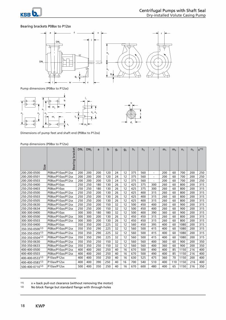
Bearing brackets P08sx to P12sx
a f x
DN2
DN1
l
i w v
g2
h2
g1
h1
r
Pump dimensions (P08sx to P12sx)
bu
t
m2
m3
m1
s1
s2
n1
i1
d1
n2n4 n3n2 n5
Dimensions of pump feet and shaft end (P08sx to P12sx)
Pump dimensions (P08sx to P12sx)
Size
Bea
rin
g b
rack
et DN1 DN2 a b g1 g2 h1 h2 r m1 m3 n1 n3 x11)
200-200-0500 P08sx/P10ax/P12sx 200 200 200 120 24 12 375 560 - 200 60 700 200 250200-200-0501 P08sx/P10ax/P12sx 200 200 200 120 24 12 375 560 - 200 60 700 200 250200-200-0503 P08sx/P10ax/P12sx 200 200 200 120 24 12 375 560 - 200 60 700 200 250250-250-0400 P08sx/P10ax 250 250 180 130 26 12 425 375 300 260 60 800 200 315250-250-0403 P08sx/P10ax 250 250 180 130 26 12 425 375 300 260 60 800 200 315250-250-0500 P08sx/P10ax/P12sx 250 250 200 130 26 12 425 400 315 260 60 800 200 315250-250-0503 P08sx/P10ax/P12sx 250 250 200 130 26 12 425 400 315 260 60 800 200 315250-250-0505 P08sx/P10ax/P12sx 250 250 200 130 26 12 425 400 315 260 60 800 200 315250-250-0630 P08sx/P10ax/P12sx 250 250 200 150 32 12 500 450 400 260 60 900 200 315250-250-0634 P08sx/P10ax/P12sx 250 250 200 150 32 12 500 450 400 260 60 900 200 315300-300-0400 P08sx/P10ax 300 300 180 180 32 12 500 400 390 360 60 900 200 315300-300-0500 P08sx/P10ax/P12sx 300 300 200 130 26 12 450 450 315 260 60 800 200 315300-300-0503 P08sx/P10ax/P12sx 300 300 200 130 26 12 450 450 315 260 60 800 200 315350-350-0400 P08sx/P10ax 350 350 200 225 32 12 560 450 395 400 60 1080 200 315350-350-050012) P08sx/P10ax/P12sx 350 350 290 225 32 12 560 500 415 400 60 1080 200 315
350-350-050312) P08sx/P10ax/P12sx 350 350 290 225 32 12 560 500 415 400 60 1080 200 315
350-350-050412) P08sx/P10ax/P12sx 350 350 290 225 32 12 560 500 415 400 60 1080 200 315350-350-0630 P08sx/P10ax/P12sx 350 350 250 150 32 12 560 560 400 360 60 900 200 350350-350-0633 P08sx/P10ax/P12sx 350 350 250 150 32 12 560 560 400 360 60 900 200 350400-400-0500 P08sx/P10ax/P12sx 400 400 260 250 40 16 670 500 490 400 85 1150 216 400400-400-0503 P08sx/P10ax/P12sx 400 400 260 250 40 16 670 500 490 400 85 1150 216 400400-400-053312) P10ax/P12sx 400 400 350 250 40 16 630 525 475 360 70 1150 200 400
400-400-058312) P10ax/P12sx 400 400 390 250 40 16 700 540 510 400 110 1150 216 400
500-400-071012) P10ax/P12sx 500 400 350 250 40 16 670 600 480 400 65 1150 216 350
11) x = back pull-out clearance (without removing the motor)12) No block flange but standard flange with through-holes
Centrifugal Pumps with Shaft SealDry-installed Volute Casing Pump
18 KWP

Size
Bea
rin
g b
rack
et DN1 DN2 a b g1 g2 h1 h2 r m1 m3 n1 n3 x11)
500-400-071312) P10ax/P12sx 500 400 350 250 40 16 670 600 480 400 65 1150 216 350
500-500-054412) P10ax/P12sx 500 500 425 250 40 30 800 630 585 400 90 1400 600 450
500-500-063012) P10ax/P12sx 500 500 375 250 40 16 750 630 575 400 100 1400 216 400
500-500-063312) P10ax/P12sx 500 500 375 250 40 16 750 630 575 400 100 1400 216 400
500-500-063412) P10ax/P12sx 500 500 375 250 40 16 750 630 575 400 100 1400 216 400
500-500-063512) P10ax/P12sx 500 500 375 250 40 16 750 630 575 400 100 1400 216 400
500-500-063712) P10ax/P12sx 500 500 375 250 40 16 750 630 575 400 100 1400 216 400
600-600-066312) P12sx 600 600 400 250 40 16 800 630 615 400 125 1400 200 500
600-600-066912) P12sx 600 600 400 250 40 16 800 630 615 400 125 1400 200 500
600-600-071012) P12sx 600 600 500 250 40 18 900 750 680 400 70 1600 200 500
Dimensions of shaft end and pump feet (P08sx to P12sx)
Bea
rin
g b
rack
et
Size
Shaft end [mm] Pump feet [mm]
d1 l t u i i1 m2 n2 n4 n5 s1 s2 f v w
P08sx 200-200-0500 75 150 97,7 20 75 39 150 560 140 - 23 18 970 220 750P08sx 200-200-0501 75 150 97,7 20 75 39 150 560 140 - 23 18 970 220 750P08sx 200-200-0503 75 150 97,7 20 75 39 150 560 140 - 23 18 970 220 750P08sx 250-250-0400 75 150 97,7 20 95 39 190 670 140 - 26 18 1000 220 780P08sx 250-250-0403 75 150 97,7 20 95 39 190 670 140 - 26 18 1000 220 780P08sx 250-250-0500 75 150 97,7 20 95 39 190 670 140 - 28 18 1000 220 780P08sx 250-250-0503 75 150 97,7 20 95 39 190 670 140 - 28 18 1000 220 780P08sx 250-250-0505 75 150 97,7 20 95 39 190 670 140 - 28 18 1000 220 780P08sx 250-250-0630 75 150 97,7 20 95 39 190 750 140 - 26 18 1000 220 780P08sx 250-250-0634 75 150 97,7 20 95 39 190 750 140 - 26 18 1000 220 780P08sx 300-300-0400 75 150 97,7 20 125 39 250 750 140 - 28 18 1000 220 780P08sx 300-300-0500 75 150 97,7 20 95 39 190 670 140 - 28 18 1000 220 780P08sx 300-300-0503 75 150 97,7 20 95 39 190 670 140 - 28 18 1000 220 780P08sx 350-350-0400 75 150 97,7 20 150 39 300 1000 140 750 28 18 1000 220 780P08sx 350-350-0500 75 150 97,7 20 150 39 300 1000 140 750 28 18 1000 220 780P08sx 350-350-0503 75 150 97,7 20 150 39 300 1000 140 750 28 18 1000 220 780P08sx 350-350-0504 75 150 97,7 20 150 39 300 1000 140 750 28 18 1000 220 780P08sx 350-350-0630 75 150 97,7 20 125 39 250 750 140 - 28 18 1000 220 780P08sx 350-350-0633 75 150 97,7 20 125 39 250 750 140 - 28 18 1000 220 780P08sx 400-400-0500 75 150 97,7 20 150 59 300 1040 140 800 39 18 1000 220 780P08sx 400-400-0503 75 150 97,7 20 150 59 300 1040 140 800 39 18 1000 220 780P10ax 200-200-0500 95 220 100,2 25 75 39 150 560 140 - 23 18 1160 410 750P10ax 200-200-0501 95 220 100,2 25 75 39 150 560 140 - 23 18 1160 410 750P10ax 200-200-0503 95 220 100,2 25 75 39 150 560 140 - 23 18 1160 410 750P10ax 250-250-0400 95 220 100,2 25 95 39 190 670 140 - 26 18 1190 410 780P10ax 250-250-0403 95 220 100,2 25 95 39 190 670 140 - 26 18 1190 410 780P10ax 250-250-0500 95 220 100,2 25 95 39 190 670 140 - 28 18 1190 410 780P10ax 250-250-0503 95 220 100,2 25 95 39 190 670 140 - 28 18 1190 410 780P10ax 250-250-0505 95 220 100,2 25 95 39 190 670 140 - 28 18 1190 410 780P10ax 250-250-0630 95 220 100,2 25 95 39 190 750 140 - 26 18 1190 410 780P10ax 250-250-0634 95 220 100,2 25 95 39 190 750 140 - 26 18 1190 410 780P10ax 300-300-0400 95 220 100,2 25 125 39 250 750 140 - 28 18 1190 410 780P10ax 300-300-0500 95 220 100,2 25 95 39 190 670 140 - 28 18 1190 410 780P10ax 300-300-0503 95 220 100,2 25 95 39 190 670 140 - 28 18 1190 410 780P10ax 350-350-0400 95 220 100,2 25 150 39 300 1000 140 750 28 18 1190 410 780P10ax 350-350-0500 95 220 100,2 25 150 39 300 1000 140 750 28 18 1190 410 780P10ax 350-350-0503 95 220 100,2 25 150 39 300 1000 140 750 28 18 1190 410 780
11) x = back pull-out clearance (without removing the motor)
Centrifugal Pumps with Shaft SealDry-installed Volute Casing Pump
KWP 19
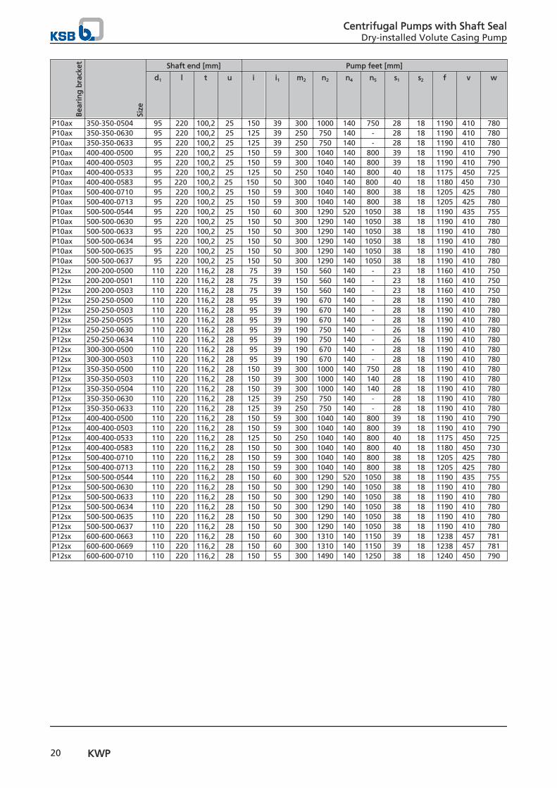
Bea
rin
g b
rack
et
Size
Shaft end [mm] Pump feet [mm]
d1 l t u i i1 m2 n2 n4 n5 s1 s2 f v w
P10ax 350-350-0504 95 220 100,2 25 150 39 300 1000 140 750 28 18 1190 410 780P10ax 350-350-0630 95 220 100,2 25 125 39 250 750 140 - 28 18 1190 410 780P10ax 350-350-0633 95 220 100,2 25 125 39 250 750 140 - 28 18 1190 410 780P10ax 400-400-0500 95 220 100,2 25 150 59 300 1040 140 800 39 18 1190 410 790P10ax 400-400-0503 95 220 100,2 25 150 59 300 1040 140 800 39 18 1190 410 790P10ax 400-400-0533 95 220 100,2 25 125 50 250 1040 140 800 40 18 1175 450 725P10ax 400-400-0583 95 220 100,2 25 150 50 300 1040 140 800 40 18 1180 450 730P10ax 500-400-0710 95 220 100,2 25 150 59 300 1040 140 800 38 18 1205 425 780P10ax 500-400-0713 95 220 100,2 25 150 59 300 1040 140 800 38 18 1205 425 780P10ax 500-500-0544 95 220 100,2 25 150 60 300 1290 520 1050 38 18 1190 435 755P10ax 500-500-0630 95 220 100,2 25 150 50 300 1290 140 1050 38 18 1190 410 780P10ax 500-500-0633 95 220 100,2 25 150 50 300 1290 140 1050 38 18 1190 410 780P10ax 500-500-0634 95 220 100,2 25 150 50 300 1290 140 1050 38 18 1190 410 780P10ax 500-500-0635 95 220 100,2 25 150 50 300 1290 140 1050 38 18 1190 410 780P10ax 500-500-0637 95 220 100,2 25 150 50 300 1290 140 1050 38 18 1190 410 780P12sx 200-200-0500 110 220 116,2 28 75 39 150 560 140 - 23 18 1160 410 750P12sx 200-200-0501 110 220 116,2 28 75 39 150 560 140 - 23 18 1160 410 750P12sx 200-200-0503 110 220 116,2 28 75 39 150 560 140 - 23 18 1160 410 750P12sx 250-250-0500 110 220 116,2 28 95 39 190 670 140 - 28 18 1190 410 780P12sx 250-250-0503 110 220 116,2 28 95 39 190 670 140 - 28 18 1190 410 780P12sx 250-250-0505 110 220 116,2 28 95 39 190 670 140 - 28 18 1190 410 780P12sx 250-250-0630 110 220 116,2 28 95 39 190 750 140 - 26 18 1190 410 780P12sx 250-250-0634 110 220 116,2 28 95 39 190 750 140 - 26 18 1190 410 780P12sx 300-300-0500 110 220 116,2 28 95 39 190 670 140 - 28 18 1190 410 780P12sx 300-300-0503 110 220 116,2 28 95 39 190 670 140 - 28 18 1190 410 780P12sx 350-350-0500 110 220 116,2 28 150 39 300 1000 140 750 28 18 1190 410 780P12sx 350-350-0503 110 220 116,2 28 150 39 300 1000 140 140 28 18 1190 410 780P12sx 350-350-0504 110 220 116,2 28 150 39 300 1000 140 140 28 18 1190 410 780P12sx 350-350-0630 110 220 116,2 28 125 39 250 750 140 - 28 18 1190 410 780P12sx 350-350-0633 110 220 116,2 28 125 39 250 750 140 - 28 18 1190 410 780P12sx 400-400-0500 110 220 116,2 28 150 59 300 1040 140 800 39 18 1190 410 790P12sx 400-400-0503 110 220 116,2 28 150 59 300 1040 140 800 39 18 1190 410 790P12sx 400-400-0533 110 220 116,2 28 125 50 250 1040 140 800 40 18 1175 450 725P12sx 400-400-0583 110 220 116,2 28 150 50 300 1040 140 800 40 18 1180 450 730P12sx 500-400-0710 110 220 116,2 28 150 59 300 1040 140 800 38 18 1205 425 780P12sx 500-400-0713 110 220 116,2 28 150 59 300 1040 140 800 38 18 1205 425 780P12sx 500-500-0544 110 220 116,2 28 150 60 300 1290 520 1050 38 18 1190 435 755P12sx 500-500-0630 110 220 116,2 28 150 50 300 1290 140 1050 38 18 1190 410 780P12sx 500-500-0633 110 220 116,2 28 150 50 300 1290 140 1050 38 18 1190 410 780P12sx 500-500-0634 110 220 116,2 28 150 50 300 1290 140 1050 38 18 1190 410 780P12sx 500-500-0635 110 220 116,2 28 150 50 300 1290 140 1050 38 18 1190 410 780P12sx 500-500-0637 110 220 116,2 28 150 50 300 1290 140 1050 38 18 1190 410 780P12sx 600-600-0663 110 220 116,2 28 150 60 300 1310 140 1150 39 18 1238 457 781P12sx 600-600-0669 110 220 116,2 28 150 60 300 1310 140 1150 39 18 1238 457 781P12sx 600-600-0710 110 220 116,2 28 150 55 300 1490 140 1250 38 18 1240 450 790
Centrifugal Pumps with Shaft SealDry-installed Volute Casing Pump
20 KWP
Bearing brackets P16ax and P20sx
Pump dimensions (P16ax and P20sx)
Dimensions of pump feet and shaft end (P16ax and P20sx)
Pump dimensions (P16ax and P20sx)
Size
Ver
sio
n
Bea
rin
g b
rack
et DN1 DN2 a b f g1 g2 h1 h2 r m1 m3 n1 n3 x13)
500-400-0710 10 P16ax 500 400 350 250 1306 40 16 670 600 480 400 180 1150 216 350500-400-0713 10 P16ax 500 400 350 250 1306 40 16 670 600 480 400 180 1150 216 350500-500-0630 10 P16ax 500 500 375 250 1190 40 14) 750 630 575 400 14) 1400 14) 400500-500-0633 10 P16ax 500 500 375 250 1190 40 14) 750 630 575 400 14) 1400 14) 400500-500-0634 10 P16ax 500 500 375 250 1190 40 14) 750 630 575 400 14) 1400 14) 400500-500-0635 10 P16ax 500 500 375 250 1190 40 14) 750 630 575 400 14) 1400 14) 400500-500-0637 10 P16ax 500 500 375 250 1190 40 14) 750 630 575 400 14) 1400 14) 400600-600-0710 10 P16ax 600 600 500 250 14) 40 14) 900 750 680 400 14) 1600 14) 500600-600-0753 10 P16ax 600 600 450 240 1296 40 25 900 680 690 400 180 1600 350 450600-600-0803 10 P16sx 600 600 450 250 1318 40 25 880 800 675 400 180 1600 350 460600-600-0813 10 P16sx 600 600 500 250 1296 40 25 900 900 730 400 180 1560 350 450600-600-0824 10 P16ax 600 600 445 250 1363 40 25 950 750 715 400 180 1560 350 500600-600-0825 10 P16ax 600 600 445 250 1363 40 25 950 750 715 400 180 1560 350 500600-600-0873 10 P16ax 600 600 470 240 1300 40 25 970 770 700 400 180 1650 350 470600-600-0923 10 P20sx 600 600 500 250 1642 40 25 900 840 730 400 210 1560 450 450700-700-0923 11 P20sx 700 700 490 250 1724 40 25 1050 690 770 500 210 1670 450 560700-700-0929 11 P20sx 700 700 490 250 1724 40 25 1050 690 770 500 210 1670 450 560800-700-0953 11 P20sx 800 700 550 210 1691,5 50 25 1100 720 770 500 210 1740 450 590800-700-0959 11 P20sx 800 700 550 210 1691,5 50 25 1100 720 770 500 210 1740 450 590
13) x = back pull-out clearance (without removing the motor)14) Dimensions on request
Centrifugal Pumps with Shaft SealDry-installed Volute Casing Pump
KWP 21

Size
Ver
sio
n
Bea
rin
g b
rack
et DN1 DN2 a b f g1 g2 h1 h2 r m1 m3 n1 n3 x13)
800-900-0883 10 P20sx 800 900 622 300 1784 50 25 1250 950 925 600 210 2250 450 660800-800-0934 11 P20sx 800 800 500 240 1711,5 50 25 1080 760 832 500 210 1840 450 610800-800-0939 11 P20sx 800 800 500 240 1711,5 50 25 1080 760 832 500 210 1840 450 610900-900-1133 11 P20sx 900 900 492 300 1732,5 50 25 1280 950 975 600 210 2200 450 695900-900-1134 11 P20sx 900 900 492 300 1732,5 50 25 1280 950 975 600 210 2200 450 695900-900-1138 11 P20sx 900 900 492 300 1732,5 50 25 1280 950 975 600 210 2200 450 695900-900-1139 11 P20sx 900 900 492 300 1732,5 50 25 1280 950 975 600 210 2200 450 695
Dimensions of shaft end and pump feet (P16ax to P20sx)
Bea
rin
g b
rack
et
Size
Ver
sio
n
Shaft end [mm] Pump feet [mm]
d1 l t u i i1 i2 m2 n2 n4 n5 n6 s1 s2 v w
P16ax 500-400-0710 10 120 210 127,2 32 150 130 85 300 1040 250 800 575 38 18 476 830P16ax 500-400-0713 10 120 210 127,2 32 150 130 85 300 1040 250 800 575 38 18 476 830P16ax 500-500-0630 10 120 210 127,2 32 150 14) 14) 300 1290 14) 1050 700 38 14) 14) 14)
P16ax 500-500-0633 10 120 210 127,2 32 150 14) 14) 300 1290 14) 1050 700 38 14) 14) 14)
P16ax 500-500-0634 10 120 210 127,2 32 150 14) 14) 300 1290 14) 1050 700 38 14) 14) 14)
P16ax 500-500-0635 10 120 210 127,2 32 150 14) 14) 300 1290 14) 1050 700 38 14) 14) 14)
P16ax 500-500-0637 10 120 210 127,2 32 150 14) 14) 300 1290 14) 1050 700 38 14) 14) 14)
P16ax 600-600-0710 10 120 210 127,2 32 150 14) 14) 300 1490 14) 1250 800 38 14) 14) 14)
P16ax 600-600-0753 10 120 210 127,2 32 150 130 85 300 1490 250 1250 800 39 17,5 476 820P16ax 600-600-0803 10 120 210 127,2 32 150 130 85 300 1490 250 1250 800 40 18 476 842P16ax 600-600-0813 10 120 210 127,2 32 150 130 85 300 1450 250 1250 780 39 17,5 476 820P16ax 600-600-0824 10 120 210 127,2 32 150 130 85 300 1450 250 1250 800 39 18 476 887P16ax 600-600-0825 10 120 210 127,2 32 150 130 85 300 1450 250 1250 800 39 18 476 887P16ax 600-600-0873 10 120 210 127,2 32 150 130 85 300 1540 250 1300 825 39 18 476 824P20sx 600-600-0923 10 145 270 153 36 150 165 110 300 1450 350 1250 800 39 17,5 658,5 983,5P20sx 700-700-0923 11 145 270 153 36 200 165 110 400 1550 350 1330 850 39 17,5 658,5 1065,5P20sx 700-700-0929 11 145 270 153 36 200 165 110 400 1550 350 1330 850 39 17,5 658,5 1065,5P20sx 800-700-0953 11 145 270 153 36 200 165 110 400 1640 350 1460 870 39 17,5 658,5 1033,5P20sx 800-700-0959 11 145 270 153 36 200 165 110 400 1640 350 1460 870 39 17,5 658,5 1033,5P20sx 800-800-0934 11 145 270 153 36 200 165 110 400 1740 350 1500 920 39 17,5 658,5 1053P20sx 800-800-0939 11 145 270 153 36 200 165 110 400 1740 350 1500 920 39 17,5 658,5 1053P20sx 800-900-0883 10 145 270 153 36 200 165 110 400 2140 350 1860 1270 39 17,5 658,5 1125P20sx 900-900-1133 11 145 270 153 36 250 165 110 500 2040 350 1800 1200 39 17,5 658,5 1075P20sx 900-900-1134 11 145 270 153 36 250 165 110 500 2040 350 1800 1200 39 17,5 658,5 1075P20sx 900-900-1138 11 145 270 153 36 250 165 110 500 2040 350 1800 1200 39 17,5 658,5 1075P20sx 900-900-1139 11 145 270 153 36 250 165 110 500 2040 350 1800 1200 39 17,5 658,5 1075
13) x = back pull-out clearance (without removing the motor)
Centrifugal Pumps with Shaft SealDry-installed Volute Casing Pump
22 KWP
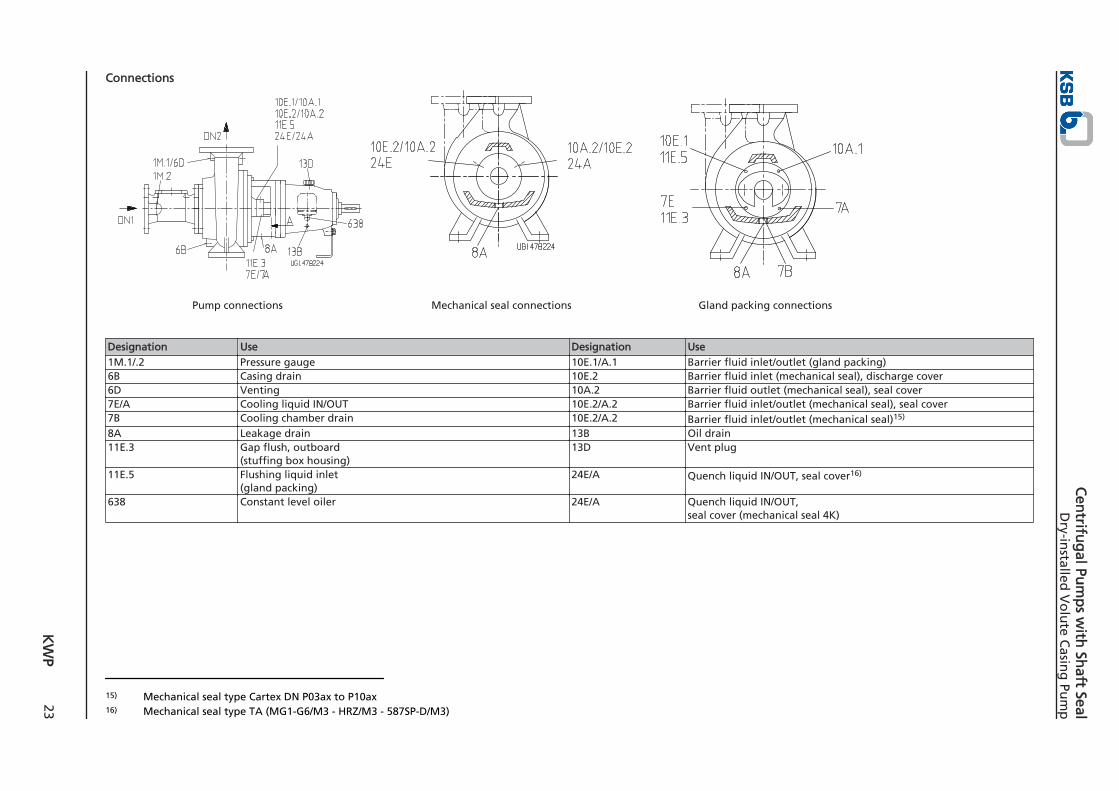
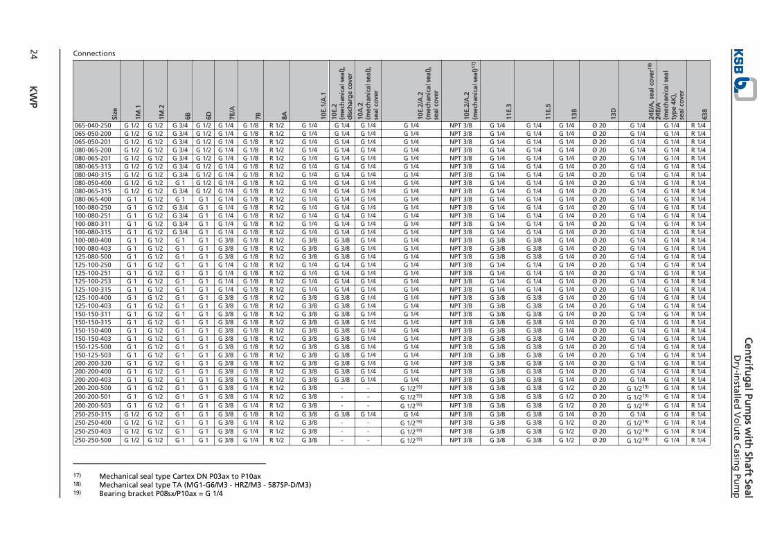
Connections
Pump connections Mechanical seal connections Gland packing connections
Designation Use Designation Use1M.1/.2 Pressure gauge 10E.1/A.1 Barrier fluid inlet/outlet (gland packing)6B Casing drain 10E.2 Barrier fluid inlet (mechanical seal), discharge cover6D Venting 10A.2 Barrier fluid outlet (mechanical seal), seal cover7E/A Cooling liquid IN/OUT 10E.2/A.2 Barrier fluid inlet/outlet (mechanical seal), seal cover7B Cooling chamber drain 10E.2/A.2 Barrier fluid inlet/outlet (mechanical seal)15)
8A Leakage drain 13B Oil drain11E.3 Gap flush, outboard
(stuffing box housing)13D Vent plug
11E.5 Flushing liquid inlet(gland packing)
24E/A Quench liquid IN/OUT, seal cover16)
638 Constant level oiler 24E/A Quench liquid IN/OUT,seal cover (mechanical seal 4K)
15) Mechanical seal type Cartex DN P03ax to P10ax16) Mechanical seal type TA (MG1-G6/M3 - HRZ/M3 - 587SP-D/M3)
K
WP
23
Cen
trifug
al Pum
ps w
ith Sh
aft SealD
ry-installed
Vo
lute C
asing
Pum
p
Connections
Size
1M.1
1M.2
6B 6D 7E/A
7B 8A 10E.
1/A
.1
10E.
2 (m
ech
anic
al s
eal)
,d
isch
arg
e co
ver
10A
.2
(mec
han
ical
sea
l),
seal
co
ver
10E.
2/A
.2(m
ech
anic
al s
eal)
, se
al c
ove
r
10E.
2/A
.2
(mec
han
ical
sea
l)17
)
11E.
3
11E.
5
13B
13D
24E/
A, s
eal c
ove
r18)
24E/
A
(mec
han
ical
sea
lty
pe
4K),
se
al c
ove
r
638
065-040-250 G 1/2 G 1/2 G 3/4 G 1/2 G 1/4 G 1/8 R 1/2 G 1/4 G 1/4 G 1/4 G 1/4 NPT 3/8 G 1/4 G 1/4 G 1/4 Ø 20 G 1/4 G 1/4 R 1/4065-050-200 G 1/2 G 1/2 G 3/4 G 1/2 G 1/4 G 1/8 R 1/2 G 1/4 G 1/4 G 1/4 G 1/4 NPT 3/8 G 1/4 G 1/4 G 1/4 Ø 20 G 1/4 G 1/4 R 1/4065-050-201 G 1/2 G 1/2 G 3/4 G 1/2 G 1/4 G 1/8 R 1/2 G 1/4 G 1/4 G 1/4 G 1/4 NPT 3/8 G 1/4 G 1/4 G 1/4 Ø 20 G 1/4 G 1/4 R 1/4080-065-200 G 1/2 G 1/2 G 3/4 G 1/2 G 1/4 G 1/8 R 1/2 G 1/4 G 1/4 G 1/4 G 1/4 NPT 3/8 G 1/4 G 1/4 G 1/4 Ø 20 G 1/4 G 1/4 R 1/4080-065-201 G 1/2 G 1/2 G 3/4 G 1/2 G 1/4 G 1/8 R 1/2 G 1/4 G 1/4 G 1/4 G 1/4 NPT 3/8 G 1/4 G 1/4 G 1/4 Ø 20 G 1/4 G 1/4 R 1/4080-065-313 G 1/2 G 1/2 G 3/4 G 1/2 G 1/4 G 1/8 R 1/2 G 1/4 G 1/4 G 1/4 G 1/4 NPT 3/8 G 1/4 G 1/4 G 1/4 Ø 20 G 1/4 G 1/4 R 1/4080-040-315 G 1/2 G 1/2 G 3/4 G 1/2 G 1/4 G 1/8 R 1/2 G 1/4 G 1/4 G 1/4 G 1/4 NPT 3/8 G 1/4 G 1/4 G 1/4 Ø 20 G 1/4 G 1/4 R 1/4080-050-400 G 1/2 G 1/2 G 1 G 1/2 G 1/4 G 1/8 R 1/2 G 1/4 G 1/4 G 1/4 G 1/4 NPT 3/8 G 1/4 G 1/4 G 1/4 Ø 20 G 1/4 G 1/4 R 1/4080-065-315 G 1/2 G 1/2 G 3/4 G 1/2 G 1/4 G 1/8 R 1/2 G 1/4 G 1/4 G 1/4 G 1/4 NPT 3/8 G 1/4 G 1/4 G 1/4 Ø 20 G 1/4 G 1/4 R 1/4080-065-400 G 1 G 1/2 G 1 G 1 G 1/4 G 1/8 R 1/2 G 1/4 G 1/4 G 1/4 G 1/4 NPT 3/8 G 1/4 G 1/4 G 1/4 Ø 20 G 1/4 G 1/4 R 1/4100-080-250 G 1 G 1/2 G 3/4 G 1 G 1/4 G 1/8 R 1/2 G 1/4 G 1/4 G 1/4 G 1/4 NPT 3/8 G 1/4 G 1/4 G 1/4 Ø 20 G 1/4 G 1/4 R 1/4100-080-251 G 1 G 1/2 G 3/4 G 1 G 1/4 G 1/8 R 1/2 G 1/4 G 1/4 G 1/4 G 1/4 NPT 3/8 G 1/4 G 1/4 G 1/4 Ø 20 G 1/4 G 1/4 R 1/4100-080-311 G 1 G 1/2 G 3/4 G 1 G 1/4 G 1/8 R 1/2 G 1/4 G 1/4 G 1/4 G 1/4 NPT 3/8 G 1/4 G 1/4 G 1/4 Ø 20 G 1/4 G 1/4 R 1/4100-080-315 G 1 G 1/2 G 3/4 G 1 G 1/4 G 1/8 R 1/2 G 1/4 G 1/4 G 1/4 G 1/4 NPT 3/8 G 1/4 G 1/4 G 1/4 Ø 20 G 1/4 G 1/4 R 1/4100-080-400 G 1 G 1/2 G 1 G 1 G 3/8 G 1/8 R 1/2 G 3/8 G 3/8 G 1/4 G 1/4 NPT 3/8 G 3/8 G 3/8 G 1/4 Ø 20 G 1/4 G 1/4 R 1/4100-080-403 G 1 G 1/2 G 1 G 1 G 3/8 G 1/8 R 1/2 G 3/8 G 3/8 G 1/4 G 1/4 NPT 3/8 G 3/8 G 3/8 G 1/4 Ø 20 G 1/4 G 1/4 R 1/4125-080-500 G 1 G 1/2 G 1 G 1 G 3/8 G 1/8 R 1/2 G 3/8 G 3/8 G 1/4 G 1/4 NPT 3/8 G 3/8 G 3/8 G 1/4 Ø 20 G 1/4 G 1/4 R 1/4125-100-250 G 1 G 1/2 G 1 G 1 G 1/4 G 1/8 R 1/2 G 1/4 G 1/4 G 1/4 G 1/4 NPT 3/8 G 1/4 G 1/4 G 1/4 Ø 20 G 1/4 G 1/4 R 1/4125-100-251 G 1 G 1/2 G 1 G 1 G 1/4 G 1/8 R 1/2 G 1/4 G 1/4 G 1/4 G 1/4 NPT 3/8 G 1/4 G 1/4 G 1/4 Ø 20 G 1/4 G 1/4 R 1/4125-100-253 G 1 G 1/2 G 1 G 1 G 1/4 G 1/8 R 1/2 G 1/4 G 1/4 G 1/4 G 1/4 NPT 3/8 G 1/4 G 1/4 G 1/4 Ø 20 G 1/4 G 1/4 R 1/4125-100-315 G 1 G 1/2 G 1 G 1 G 1/4 G 1/8 R 1/2 G 1/4 G 1/4 G 1/4 G 1/4 NPT 3/8 G 1/4 G 1/4 G 1/4 Ø 20 G 1/4 G 1/4 R 1/4125-100-400 G 1 G 1/2 G 1 G 1 G 3/8 G 1/8 R 1/2 G 3/8 G 3/8 G 1/4 G 1/4 NPT 3/8 G 3/8 G 3/8 G 1/4 Ø 20 G 1/4 G 1/4 R 1/4125-100-403 G 1 G 1/2 G 1 G 1 G 3/8 G 1/8 R 1/2 G 3/8 G 3/8 G 1/4 G 1/4 NPT 3/8 G 3/8 G 3/8 G 1/4 Ø 20 G 1/4 G 1/4 R 1/4150-150-311 G 1 G 1/2 G 1 G 1 G 3/8 G 1/8 R 1/2 G 3/8 G 3/8 G 1/4 G 1/4 NPT 3/8 G 3/8 G 3/8 G 1/4 Ø 20 G 1/4 G 1/4 R 1/4150-150-315 G 1 G 1/2 G 1 G 1 G 3/8 G 1/8 R 1/2 G 3/8 G 3/8 G 1/4 G 1/4 NPT 3/8 G 3/8 G 3/8 G 1/4 Ø 20 G 1/4 G 1/4 R 1/4150-150-400 G 1 G 1/2 G 1 G 1 G 3/8 G 1/8 R 1/2 G 3/8 G 3/8 G 1/4 G 1/4 NPT 3/8 G 3/8 G 3/8 G 1/4 Ø 20 G 1/4 G 1/4 R 1/4150-150-403 G 1 G 1/2 G 1 G 1 G 3/8 G 1/8 R 1/2 G 3/8 G 3/8 G 1/4 G 1/4 NPT 3/8 G 3/8 G 3/8 G 1/4 Ø 20 G 1/4 G 1/4 R 1/4150-125-500 G 1 G 1/2 G 1 G 1 G 3/8 G 1/8 R 1/2 G 3/8 G 3/8 G 1/4 G 1/4 NPT 3/8 G 3/8 G 3/8 G 1/4 Ø 20 G 1/4 G 1/4 R 1/4150-125-503 G 1 G 1/2 G 1 G 1 G 3/8 G 1/8 R 1/2 G 3/8 G 3/8 G 1/4 G 1/4 NPT 3/8 G 3/8 G 3/8 G 1/4 Ø 20 G 1/4 G 1/4 R 1/4200-200-320 G 1 G 1/2 G 1 G 1 G 3/8 G 1/8 R 1/2 G 3/8 G 3/8 G 1/4 G 1/4 NPT 3/8 G 3/8 G 3/8 G 1/4 Ø 20 G 1/4 G 1/4 R 1/4200-200-400 G 1 G 1/2 G 1 G 1 G 3/8 G 1/8 R 1/2 G 3/8 G 3/8 G 1/4 G 1/4 NPT 3/8 G 3/8 G 3/8 G 1/4 Ø 20 G 1/4 G 1/4 R 1/4200-200-403 G 1 G 1/2 G 1 G 1 G 3/8 G 1/8 R 1/2 G 3/8 G 3/8 G 1/4 G 1/4 NPT 3/8 G 3/8 G 3/8 G 1/4 Ø 20 G 1/4 G 1/4 R 1/4200-200-500 G 1 G 1/2 G 1 G 1 G 3/8 G 1/4 R 1/2 G 3/8 - - G 1/219) NPT 3/8 G 3/8 G 3/8 G 1/2 Ø 20 G 1/219) G 1/4 R 1/4200-200-501 G 1 G 1/2 G 1 G 1 G 3/8 G 1/4 R 1/2 G 3/8 - - G 1/219) NPT 3/8 G 3/8 G 3/8 G 1/2 Ø 20 G 1/219) G 1/4 R 1/4200-200-503 G 1 G 1/2 G 1 G 1 G 3/8 G 1/4 R 1/2 G 3/8 - - G 1/219) NPT 3/8 G 3/8 G 3/8 G 1/2 Ø 20 G 1/219) G 1/4 R 1/4250-250-315 G 1/2 G 1/2 G 1 G 1 G 3/8 G 1/8 R 1/2 G 3/8 G 3/8 G 1/4 G 1/4 NPT 3/8 G 3/8 G 3/8 G 1/4 Ø 20 G 1/4 G 1/4 R 1/4250-250-400 G 1/2 G 1/2 G 1 G 1 G 3/8 G 1/4 R 1/2 G 3/8 - - G 1/219) NPT 3/8 G 3/8 G 3/8 G 1/2 Ø 20 G 1/219) G 1/4 R 1/4250-250-403 G 1/2 G 1/2 G 1 G 1 G 3/8 G 1/4 R 1/2 G 3/8 - - G 1/219) NPT 3/8 G 3/8 G 3/8 G 1/2 Ø 20 G 1/219) G 1/4 R 1/4250-250-500 G 1/2 G 1/2 G 1 G 1 G 3/8 G 1/4 R 1/2 G 3/8 - - G 1/219) NPT 3/8 G 3/8 G 3/8 G 1/2 Ø 20 G 1/219) G 1/4 R 1/4
17) Mechanical seal type Cartex DN P03ax to P10ax18) Mechanical seal type TA (MG1-G6/M3 - HRZ/M3 - 587SP-D/M3)19) Bearing bracket P08sx/P10ax = G 1/4
24K
WP
Cen
trifug
al Pum
ps w
ith Sh
aft SealD
ry-installed
Vo
lute C
asing
Pum
p

Size
1M.1
1M.2
6B 6D 7E/A
7B 8A 10E.
1/A
.1
10E.
2 (m
ech
anic
al s
eal)
,d
isch
arg
e co
ver
10A
.2
(mec
han
ical
sea
l),
seal
co
ver
10E.
2/A
.2(m
ech
anic
al s
eal)
, se
al c
ove
r
10E.
2/A
.2
(mec
han
ical
sea
l)17
)
11E.
3
11E.
5
13B
13D
24E/
A, s
eal c
ove
r18)
24E/
A
(mec
han
ical
sea
l typ
e 4K
),
seal
co
ver
638
250-250-503 G 1/2 G 1/2 G 1 G 1 G 3/8 G 1/4 R 1/2 G 3/8 - - G 1/219) NPT 3/8 G 3/8 G 3/8 G 1/2 Ø 20 G 1/219) G 1/4 R 1/4250-250-505 G 1/2 G 1/2 G 1 G 1 G 3/8 G 1/4 R 1/2 G 3/8 - - G 1/219) NPT 3/8 G 3/8 G 3/8 G 1/2 Ø 20 G 1/219) G 1/4 R 1/4250-250-630 G 1/2 G 1/2 G 1 G 1 G 3/8 G 1/4 R 1/2 G 3/8 - - G 1/219) NPT 3/8 G 3/8 G 3/8 G 1/2 Ø 20 G 1/219) G 1/4 R 1/4250-250-634 G 1/2 G 1/2 G 1 G 1 G 3/8 G 1/4 R 1/2 G 3/8 - - G 1/219) NPT 3/8 G 3/8 G 3/8 G 1/2 Ø 20 G 1/219) G 1/4 R 1/4300-300-400 G 1/2 G 1/2 G 1 G 1 G 3/8 G 1/4 R 1/2 G 3/8 - - G 1/219) NPT 3/8 G 3/8 G 3/8 G 1/2 Ø 20 G 1/219) G 1/4 R 1/4300-300-500 G 1/2 G 1/2 G 1 G 1 G 3/8 G 1/4 R 1/2 G 3/8 - - G 1/219) NPT 3/8 G 3/8 G 3/8 G 1/2 Ø 20 G 1/219) G 1/4 R 1/4300-300-503 G 1/2 G 1/2 G 1 G 1 G 3/8 G 1/4 R 1/2 G 3/8 - - G 1/219) NPT 3/8 G 3/8 G 3/8 G 1/2 Ø 20 G 1/219) G 1/4 R 1/4350-350-400 G 1/2 G 1/2 G 1 G 1 G 3/8 G 1/4 R 1/2 G 3/8 - - G 1/219) NPT 3/8 G 3/8 G 3/8 G 1/2 Ø 20 G 1/219) G 1/4 R 1/4350-350-500 G 1/2 G 1/2 G 1 G 1 G 3/8 G 1/4 R 1/2 G 3/8 - - G 1/219) NPT 3/8 G 3/8 G 3/8 G 1/2 Ø 20 G 1/219) G 1/4 R 1/4350-350-503 G 1/2 G 1/2 G 1 G 1 G 3/8 G 1/4 R 1/2 G 3/8 - - G 1/219) NPT 3/8 G 3/8 G 3/8 G 1/2 Ø 20 G 1/219) G 1/4 R 1/4350-350-504 G 1/2 G 1/2 G 1 G 1 G 3/8 G 1/4 R 1/2 G 3/8 - - G 1/219) NPT 3/8 G 3/8 G 3/8 G 1/2 Ø 20 G 1/219) G 1/4 R 1/4350-350-630 G 1/2 G 1/2 G 1 G 1 G 3/8 G 1/4 R 1/2 G 3/8 - - G 1/219) NPT 3/8 G 3/8 G 3/8 G 1/2 Ø 20 G 1/219) G 1/4 R 1/4350-350-633 G 1/2 G 1/2 G 1 G 1 G 3/8 G 1/4 R 1/2 G 3/8 - - G 1/219) NPT 3/8 G 3/8 G 3/8 G 1/2 Ø 20 G 1/219) G 1/4 R 1/4400-400-500 G 1/2 G 1/2 G 1 1/2 G 2 G 3/8 G 1/4 R 1/2 G 3/8 - - G 1/219) NPT 3/8 G 3/8 G 3/8 G 1/2 Ø 20 G 1/219) G 1/420) R 1/4400-400-503 G 1/2 G 1/2 G 1 1/2 G 2 G 3/8 G 1/4 R 1/2 G 3/8 - - G 1/219) NPT 3/8 G 3/8 G 3/8 G 1/2 Ø 20 G 1/219) G 1/420) R 1/4400-400-533 G 1/2 G 1/2 G 1 1/2 G 2 G 3/8 G 1/4 R 1/2 G 3/8 - - G 1/219) NPT 3/8 G 3/8 G 3/8 G 1/2 Ø 20 G 1/219) G 1/420) R 1/4400-400-583 G 1/2 G 1/2 G 1 1/2 G 2 G 3/8 G 1/4 R 1/2 G 3/8 - - G 1/219) NPT 3/8 G 3/8 G 3/8 G 1/2 Ø 20 G 1/219) G 1/420) R 1/4500-400-710 G 1/2 G 1/2 G 1 1/2 G 2 G 3/8 G 1/4 R 1/2 G 3/820) - - G 1/219)20) NPT 3/820) G 3/820) G 3/820) G 1/2 Ø 20 G 1/219)20) G 1/420) R 1/4500-400-713 G 1/2 G 1/2 G 1 1/2 G 2 G 3/8 G 1/4 R 1/2 G 3/820) - - G 1/219)20) NPT 3/820) G 3/820) G 3/820) G 1/2 Ø 20 G 1/219)20) G 1/420) R 1/4500-500-544 G 1/2 G 1/2 G 1 1/2 G 2 G 3/8 G 1/4 R 1/2 G 3/8 - - G 1/219) NPT 3/8 G 3/8 G 3/8 G 1/2 Ø 20 G 1/219) G 1/4 R 1/4500-500-630 G 1/2 G 1/2 G 1 1/2 G 2 G 3/8 G 1/4 R 1/2 G 3/820) - - G 1/219)20) NPT 3/820) G 3/820) G 3/820) G 1/2 Ø 20 G 1/219)20) G 1/420) R 1/4500-500-633 G 1/2 G 1/2 G 1 1/2 G 2 G 3/8 G 1/4 R 1/2 G 3/820) - - G 1/219)20) NPT 3/820) G 3/820) G 3/820) G 1/2 Ø 20 G 1/219)20) G 1/420) R 1/4500-500-634 G 1/2 G 1/2 G 1 1/2 G 2 G 3/8 G 1/4 R 1/2 G 3/820) - - G 1/219)20) NPT 3/820) G 3/820) G 3/820) G 1/2 Ø 20 G 1/219)20) G 1/420) R 1/4500-500-635 G 1/2 G 1/2 G 1 1/2 G 2 G 3/8 G 1/4 R 1/2 G 3/820) - - G 1/219)20) NPT 3/820) G 3/820) G 3/820) G 1/2 Ø 20 G 1/219)20) G 1/420) R 1/4500-500-637 G 1/2 G 1/2 G 1 1/2 G 2 G 3/8 G 1/4 R 1/2 G 3/820) - - G 1/219)20) NPT 3/820) G 3/820) G 3/820) G 1/2 Ø 20 G 1/219)20) G 1/420) R 1/4600-600-663 G 1/2 G 1/2 G 1 1/2 G 2 G 3/8 G 1/4 R 1/2 G 3/8 - - G 1/219) NPT 3/8 G 3/8 G 3/8 G 1/2 Ø 20 G 1/219) G 1/4 R 1/4600-600-669 G 1/2 G 1/2 G 1 1/2 G 2 G 3/8 G 1/4 R 1/2 G 3/8 - - G 1/219) NPT 3/8 G 3/8 G 3/8 G 1/2 Ø 20 G 1/219) G 1/4 R 1/4600-600-710 G 1/2 G 1/2 G 1 1/2 G 2 G 3/8 G 1/4 R 1/2 G 3/8 - - G 1/219) NPT 3/8 G 3/8 G 3/8 G 1/2 Ø 20 G 1/219) G 1/4 R 1/4600-600-753 - - - - - - R 1 1/2 - - - - - - - G 1/2 Ø 20 - - R 1/4600-600-803 - - - - - - R 1 1/2 - - - - - - - G 1/2 Ø 20 - - R 1/4600-600-813 - - - - - - R 1 1/2 - - - - - - - G 1/2 Ø 20 - - R 1/4600-600-824 - - - - - - R 1 1/2 - - - - - - - G 1/2 Ø 20 - - R 1/4600-600-825 - - - - - - R 1 1/2 - - - - - - - G 1/2 Ø 20 - - R 1/4600-600-873 - - - - - - R 1 1/2 - - - - - - - G 1/2 Ø 20 - - R 1/4600-600-923 - - - - - - R 1 1/2 - - - - - - - G 1/2 Ø 20 - - R 1/4700-700-923 - - - - - - R 1 1/2 - - - - - - - G 1/2 Ø 20 - - R 1/4
17) Mechanical seal type Cartex DN P03ax to P10ax18) Mechanical seal type TA (MG1-G6/M3 - HRZ/M3 - 587SP-D/M3)20) Not provided on this size with bearing bracket P16ax
K
WP
25
Cen
trifug
al Pum
ps w
ith Sh
aft SealD
ry-installed
Vo
lute C
asing
Pum
p

Size
1M.1
1M.2
6B 6D 7E/A
7B 8A 10E.
1/A
.1
10E.
2 (m
ech
anic
al s
eal)
,d
isch
arg
e co
ver
10A
.2
(mec
han
ical
sea
l),
seal
co
ver
10E.
2/A
.2(m
ech
anic
al s
eal)
, se
al c
ove
r
10E.
2/A
.2
(mec
han
ical
sea
l)17
)
11E.
3
11E.
5
13B
13D
24E/
A, s
eal c
ove
r18)
24E/
A
(mec
han
ical
sea
l typ
e 4K
),
seal
co
ver
638
700-700-929 - - - - - - R 1 1/2 - - - - - - - G 1/2 Ø 20 - - R 1/4700-700-953 - - - - - - R 1 1/2 - - - - - - - G 1/2 Ø 20 - - R 1/4700-700-959 - - - - - - R 1 1/2 - - - - - - - G 1/2 Ø 20 - - R 1/4800-800-934 - - - - - - R 1 1/2 - - - - - - - G 1/2 Ø 20 - - R 1/4800-800-935 - - - - - - R 1 1/2 - - - - - - - G 1/2 Ø 20 - - R 1/4800-800-939 - - - - - - R 1 1/2 - - - - - - - G 1/2 Ø 20 - - R 1/4800-900-883 - - - - - - R 1 1/2 - - - - - - - G 1/2 Ø 20 - - R 1/4900-900-1133 - - - - - - R 1 1/2 - - - - - - - G 1/2 Ø 20 - - R 1/4900-900-1134 - - - - - - R 1 1/2 - - - - - - - G 1/2 Ø 20 - - R 1/4900-900-1138 - - - - - - R 1 1/2 - - - - - - - G 1/2 Ø 20 - - R 1/4900-900-1139 - - - - - - R 1 1/2 - - - - - - - G 1/2 Ø 20 - - R 1/4
17) Mechanical seal type Cartex DN P03ax to P10ax18) Mechanical seal type TA (MG1-G6/M3 - HRZ/M3 - 587SP-D/M3)
26K
WP
Cen
trifug
al Pum
ps w
ith Sh
aft SealD
ry-installed
Vo
lute C
asing
Pum
p
Coating and preservation
▪ Coating and preservation to KSB standard
Product benefits
▪ Easy to service thanks to back pull-out design
▪ Safe design: all pressure-retaining components cast withextra corrosion/wear allowance.
▪ Standard pump with suction-side wear plate in wear-resistant diagonal gap design
▪ High levels of efficiency with channel-type impeller;impeller with front vanes and diagonal gap; back vanesreduce axial thrust
▪ Dry shaft: no special materials required
▪ Bearing assembly in reinforced, adjustable design
▪ Mechanical seal fitted in conical shaft seal chamber foroptimum circulation around the mechanical seal, ventingand drainage of the shaft seal chamber
Acceptance tests / Warranties
▪ Materials testing
– Test report 2.2 on request
▪ Final inspection
– Inspection certificate 3.1 to EN 10204 on request
▪ Hydraulic test
The duty point of each pump is guaranteed according toISO 9906.
The following acceptance tests can be performed andcertified at extra charge:
– Performance test to ISO 9906
– NPSH test
▪ Other tests (e.g. vibrations, strength) on request.
▪ Warranties
Warranties are given within the scope of the valid deliveryconditions.
Centrifugal Pumps with Shaft SealDry-installed Volute Casing Pump
KWP 27

General assembly drawings with list of components
Bearing brackets P03ax to P06x
Bearing brackets P03ax to P06x
Centrifugal Pumps with Shaft SealDry-installed Volute Casing Pump
28 KWP

Bearing brackets P08sx to P12sx
Bearing brackets P08sx to P12sx
Centrifugal Pumps with Shaft SealDry-installed Volute Casing Pump
KWP 29

Bearing brackets P10ax to P12sx: sizes 500-400-710 and 500-400-713
Centrifugal Pumps with Shaft SealDry-installed Volute Casing Pump
30 KWP
Bearing bracket P12sx: sizes 500-500-544, 600-660-663 and 600-600-669
Centrifugal Pumps with Shaft SealDry-installed Volute Casing Pump
KWP 31
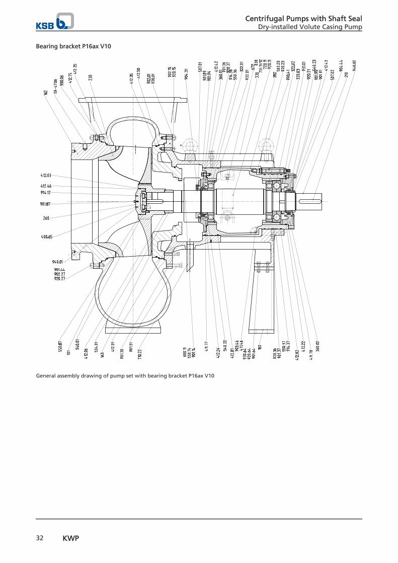
Bearing bracket P16ax V10
General assembly drawing of pump set with bearing bracket P16ax V10
Centrifugal Pumps with Shaft SealDry-installed Volute Casing Pump
32 KWP
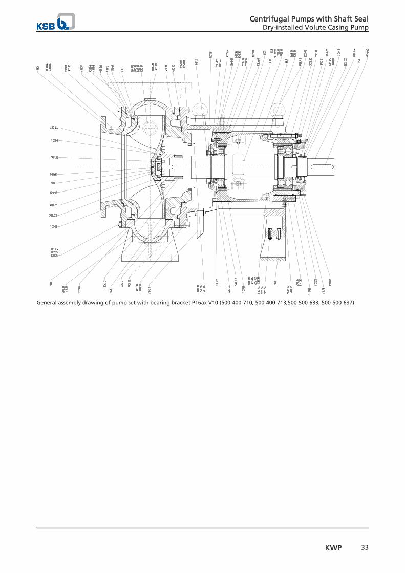
General assembly drawing of pump set with bearing bracket P16ax V10 (500-400-710, 500-400-713,500-500-633, 500-500-637)
Centrifugal Pumps with Shaft SealDry-installed Volute Casing Pump
KWP 33
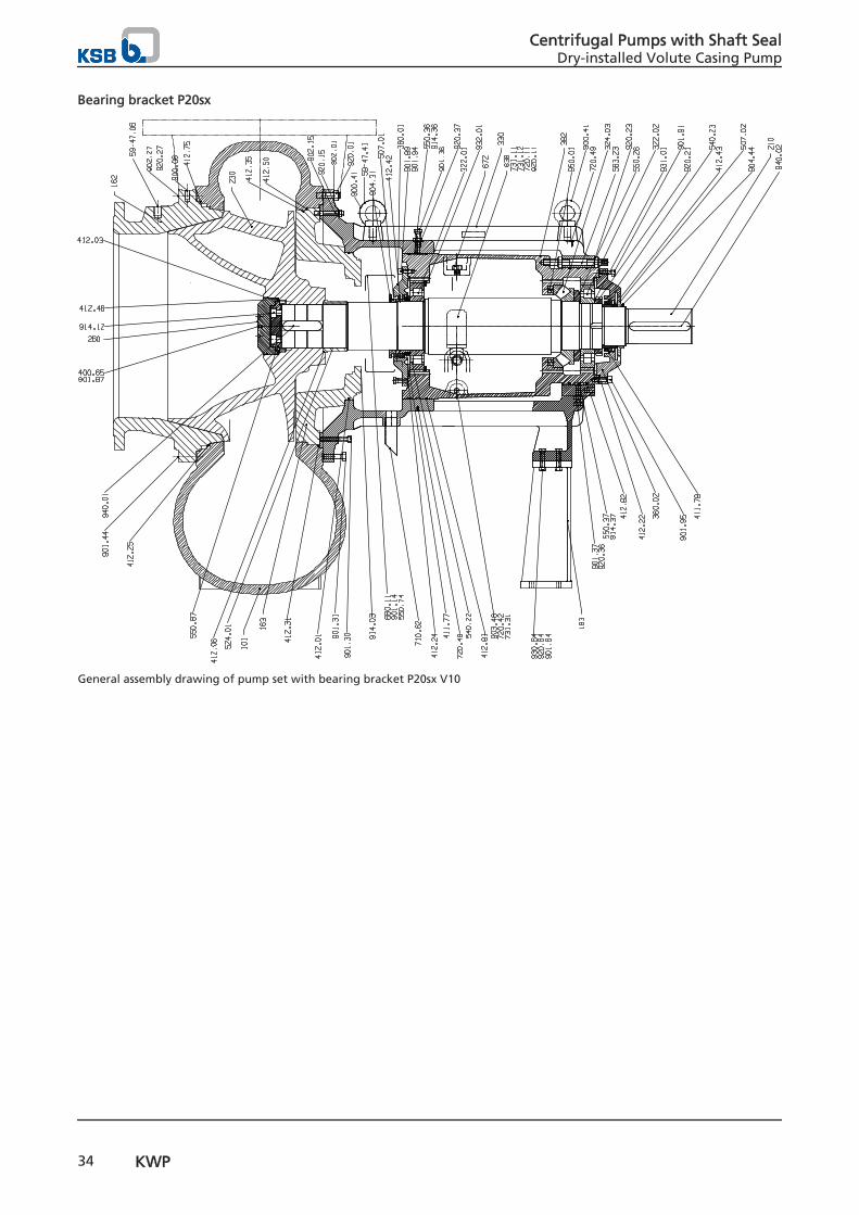
Bearing bracket P20sx
General assembly drawing of pump set with bearing bracket P20sx V10
Centrifugal Pumps with Shaft SealDry-installed Volute Casing Pump
34 KWP
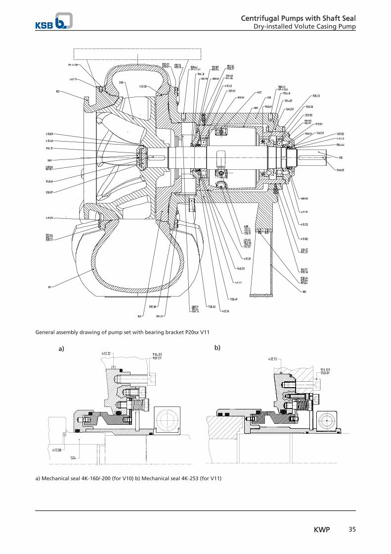
General assembly drawing of pump set with bearing bracket P20sx V11
a) b)
a) Mechanical seal 4K-160/-200 (for V10) b) Mechanical seal 4K-253 (for V11)
Centrifugal Pumps with Shaft SealDry-installed Volute Casing Pump
KWP 35
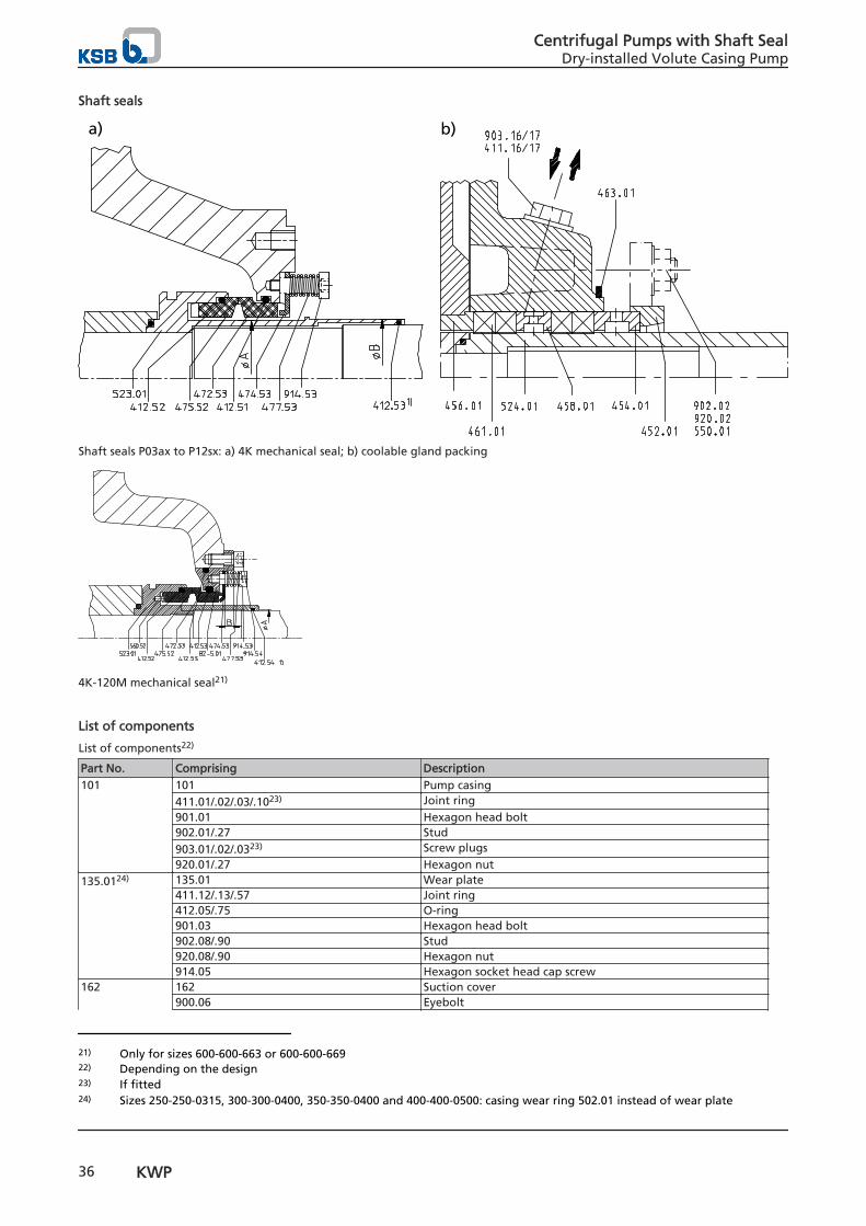
Shaft seals
a) b)
Shaft seals P03ax to P12sx: a) 4K mechanical seal; b) coolable gland packing
4K-120M mechanical seal21)
List of components
List of components22)
Part No. Comprising Description101 101 Pump casing
411.01/.02/.03/.1023) Joint ring901.01 Hexagon head bolt902.01/.27 Stud903.01/.02/.0323) Screw plugs920.01/.27 Hexagon nut
135.0124) 135.01 Wear plate411.12/.13/.57 Joint ring412.05/.75 O-ring901.03 Hexagon head bolt902.08/.90 Stud920.08/.90 Hexagon nut914.05 Hexagon socket head cap screw
162 162 Suction cover900.06 Eyebolt
21) Only for sizes 600-600-663 or 600-600-66922) Depending on the design23) If fitted24) Sizes 250-250-0315, 300-300-0400, 350-350-0400 and 400-400-0500: casing wear ring 502.01 instead of wear plate
Centrifugal Pumps with Shaft SealDry-installed Volute Casing Pump
36 KWP

Part No. Comprising Description901.44 Forcing screw904.97 Grub screw
163 163 Discharge cover (A-type cover)412.35/.50 O-ring900.07 Eyebolt901.22/.30/.31 Forcing screw902.15 Stud920.15 Hexagon nut
163 163 Discharge cover with integrally cast stuffing box housing411.16/.17 Joint ring463.01 Drip plate550.01 Disc901.22 Hexagon head bolt902.02 Stud903.16/.17 Screw plug920.02 Nut
163 163 Discharge cover (with bolted stuffing box housing)400.05 Gasket411.26 Joint ring901.22 Hexagon head bolt
183 183 Support foot592.02 Base901.04 Hexagon head bolt914.04 Hexagon socket head cap screw930.01 Spring washer89-4.02 Shims
210 210 Shaft500.21 Ring920.21 Slotted round nut931.01 Lock washer940.01/.02 Key
230 230 Impeller260 260 Impeller hub cap
412.03 O-ring550.87 Disc901.87 Hexagon head bolt931.02 Lock washer
320.02 320.02 Angular contact ball bearing322.01 322.01 Cylindrical roller bearing330 330 Bearing bracket330 330 Bearing bracket, complete
360.01 Bearing cover382 Bearing carrier400.01 Gasket411.46 Joint ring411.77/.78 V-ring412.02/.36 O-ring421.01/.02 Lip seal507.01/.12 Thrower550.23 Support disc638 Constant level oiler672 Vent plug901.91/.95 Hexagon head bolt903.10/.46 Screw plug914.01/.02 Hexagon socket head cap screw932.01./.02/.03 Circlip
344 344 Bearing bracket lantern901.31 Forcing screw902.04 Stud920.04 Hexagon nut901.22 Hexagon head bolt
360.01 360.01 Bearing cover400.01 Gasket914.01 Hexagon socket head cap screw507.11 Thrower
Centrifugal Pumps with Shaft SealDry-installed Volute Casing Pump
KWP 37

Part No. Comprising Description412.36 O-ring
382 382 Bearing carrier412.02 O-ring89-4.12 Shims
411.77/.78 411.77/.78 V-ring433.02 82-5.01 Adapter
412.51/.52/.53 O-ring433.02 Mechanical seal, type 4K471 Seal cover472.51 Primary ring474.53 Thrust ring475.52 Mating ring477.53 Spring523.01 Shaft sleeve560.52 Pin914.53/.54 Hexagon socket head cap screw
451.01 451.01 Stuffing box housing400.05 Gasket411.16/.17/.18/.19/.26 Joint ring463.01 Drip plate550.01 Disc902.02 Stud903.16/.17/.18/.19 Screw plug920.01 Hexagon nut
452.01 452.01 Gland follower454.01 454.01 Stuffing box ring, split456.01 456.01 Neck bush458.01 458.01 Lantern ring, split461.01 461.01 Gland packing59-47.06/.08/.41 59-47.06/.08/.41 Lifting lug502.01 502.01 Casing wear ring507.01/.11/.12 507.01/.11/.12 Thrower524.01 524.01 Shaft protecting sleeve
412.06 O-ring900.06/.07/.41 900.06/.07/.41 Eyebolt906 906 Impeller screw
412.03 O-ring99-9 99-9 Set of sealing elements
400.01 Gasket411.01/.02/.03/.10/.12/.13/.46./57 Joint ring412.02/.03/.05/.06/.35/.50/.75 O-ring
Detailed designation
Product code example
Position
1 2 3 4 5 6 7 8 9 10 11 12 13 14 15 16 17 18 19 20 21 22 23 24 25 26 27 28 29 30 31 32 33K W P F 1 2 5 - 1 0 0 - 0 2 5 0 G N N G 1 0 P 4 X 3 N H 5 5 4
See name plate and data sheet See data sheet
Key to the designation
Position Code Description1-3 Pump type
KWP Type series
4 Impeller K Channel impeller
O Open impellerF Free-flow impellerR Worm-type impeller
5-17 Size 125 Nominal suction nozzle diameter [mm]
100 Nominal discharge nozzle diameter [mm]
Centrifugal Pumps with Shaft SealDry-installed Volute Casing Pump
38 KWP

Position Code Description250 Nominal impeller diameter [mm]
18 Casing material G GJL-250
D NORIDUR 1.4593H NORIHARD NH 15 3K GJS-400-18-LT/ CeramikPolySiC
19 Impeller material N ERN
D NORIDUR 1.4593U NORIDUR 1.4593 DASH NORIHARD NH 15 3K CeramikPolySiCM NORICROM 1.4475
20 Wear plate material N ERN
D NORIDUR 1.4593U NORIDUR 1.4593 DASH NORIHARD NH 15 3K25) CeramikPolySiCM NORICROM 1.4475
21 Discharge cover material G GJL-250
D NORIDUR 1.4593H NORIHARD NH 15 3M NORICROM 1.4475K CeramikPolySiC
22-23 Design variant 10
1124-25 Shaft seal operating mode
P3 Gland packing (arrangement I = 2/1/2) for barrier fluidP6 Gland packing (arrangement II = 1/1/3) for barrier fluidP4 Gland packing (arrangement IIa = -/1/3) for flushing liquidA Single mechanical seal in A-type coverTA Double mechanical seal in A-type cover, unpressurisedTS Double mechanical seal in A-type cover, with barrier fluidDR Double mechanical seal in cylindrical cover, with barrier fluidCA Single cartridge sealCBA Double cartridge seal with barrier fluid
26 Special design X Special design
- Standard27-29 Installation type
0 Figure 03N Fig. 3E, baseplate, non-spacer-type coupling3NH Fig. 3E, baseplate, spacer-type couplingBH Close-coupled, horizontalBV Close-coupled, vertical
30-32 Motor rating 1 3 2 132 kW
5 5 55 kW33 Number of poles
2 2-pole4 4-pole6 6-pole
25) K defines a suction cover in GJS-400-18-LT/ CeramikPolySiC for pumps without a separate wear plate
Centrifugal Pumps with Shaft SealDry-installed Volute Casing Pump
KWP 39

2361
.5/1
0-EN
18.0
9.20
14
KSB Aktiengesellschaft67225 Frankenthal • Johann-Klein-Str. 9 • 67227 Frankenthal (Germany)Tel. +49 6233 86-0 • Fax +49 6233 86-3401www.ksb.com