kurnell ports and berthing facility
TRANSCRIPT
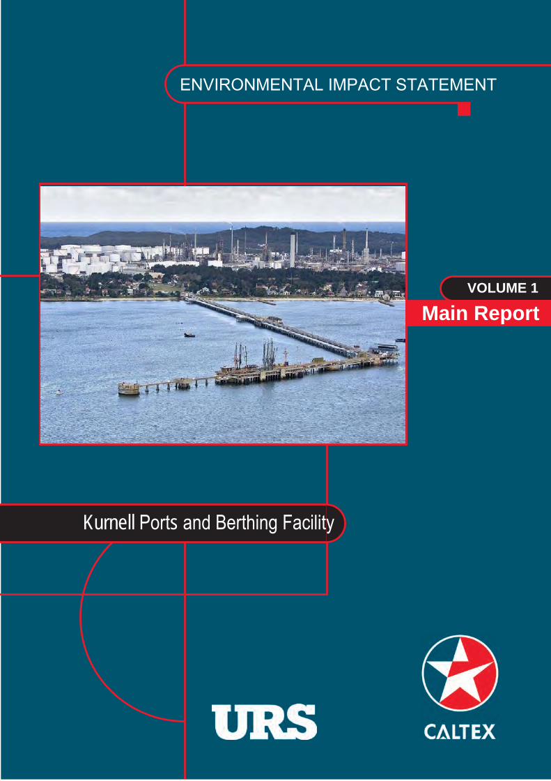
ENVIRONMENTAL IMPACT STATEMENT
Kurnell Ports and Berthing Facility
VOLUME 1
Main Report

Statement of Validity
Submission of Environmental Assessment
Prepared as ‘State Significant Development’ under Part 4 of the Environmental Planning and Assessment Act 1979
Environmental Assessment prepared by
Role Project Director Project Manager Name William Miles Chris Fay
Position Senior Associate – Environmental Planner Associate - Environmental Planner
Qualifications M.EIANZ, MSc, BSc (Hons) M.EIANZ, C.WEM, M.CIWEM, C.SocENV, MSc., BSc (Hons)
Address:
URS Australia Pty Ltd Level 4 407 Pacific Highway ARTARMON NSW 2064
In respect of
Applicant and Land Details
Applicant Caltex Refineries (NSW) Pty Ltd 2 Solander Street, Kurnell, NSW, 2231
Subject Site Caltex is proposing to undertake port and berthing facility located in Botany Bay. The facility includes the Kurnell Wharf, two fixed berths, a submarine (sub) berth, and an associated turning circle and shipping approaches that interface with the Botany Bay Shipping Channel.
Project Summary
The proposed works include:
dredging 153,000 m3 of sediment from spot locations within the berths, approaches and turning circle (totaling an area of approximately 172,500 m2);
increasing the size of the existing fixed berths;
disposing of the majority of the dredged sediments at the Sydney Offshore Spoil Ground (permitted separately under the Commonwealth Environment Protection (Sea Dumping) Act 1981);
reusing up to 7,800 m3 of the dredged sediments to cover an exposed section of the Kurnell Refinery subsea fuel pipelines located behind the sub berth and a former anchor point at the entry to the sub berth;
upgrading the mooring and berthing infrastructure associated with fixed berth #1 and the sub berth;
upgrading the fuel loading and unloading equipment used for fixed berth #1;
relocating the launch jetty from the east side of the Wharf to the west side;
installing a rock revetment and sheet piled wall at the back of fixed berth #1;
upgrading the firewater equipment on the Wharf;
ancillary works including the -, installation of steel truss walkway, strengthening works to the breasting island and upgrade to the fender panels; and
allowing for continued operation and on-going maintenance (including future dredging).
Lot and DP Kurnell Wharf – Lot 456 DP 141 3279. Remainder of project site: Unincorporated land.

Environmental Impact Statement
An Environmental Impact Statement (EIS) is attached. The EIS assesses the environmental impacts of
this project and includes the matters referred to in Director-General’s Requirements provided to the
Proponent on the 9 August 2012 under Section 78A(8A) of the Environmental Planning and Assessment
Act 1979.
Declaration
I certify that I have prepared the contents of the Environmental Assessment in accordance with the
requirements of the Environmental Planning and Assessment Act 1979 and Regulation and that, to the
best of my knowledge, the information contained in this report is not false or misleading.
Signature:
Date: February 2013
Name: CHRIS FAY

E n v i r o n m e n t a l I m p a c t S t a t e m e n t T a b l e o f C o n t e n t s
Kurnell Port and Berthing Facility Upgrade i
Statement of Validity Table of Contents ...................................................................................................................................... i List of Tables, Figures and Volumes ........................................................................................................ v Limitations ................................................................................................................................................ ix Notes on Text .......................................................................................................................................... xi Abbreviations ......................................................................................................................................... xiii Glossary ................................................................................................................................................ xvii
Executive Summary ........................................................................................................................ ES-1
1 Introduction............................................................................................................................... 1-1 1.1 Context ........................................................................................................................................ 1-1 1.2 The Kurnell Port and Berthing Facility .......................................................................................... 1-1 1.3 Works Overview and Objectives .................................................................................................. 1-1 1.4 The Applicant and Project Team .................................................................................................. 1-2 1.5 EIS Exhibition and Determination ................................................................................................ 1-6 1.6 EIS Structure................................................................................................................................ 1-6 1.7 Standard Terms and Definitions Used in the EIS ......................................................................... 1-8
2 Proposed Works Need and Alternatives ................................................................................ 2-1 2.1 Introduction .................................................................................................................................. 2-1 2.2 Strategic Need ............................................................................................................................. 2-1 2.3 Project Need ................................................................................................................................ 2-2 2.4 Objectives .................................................................................................................................... 2-2 2.5 Alternatives .................................................................................................................................. 2-3 2.6 Conclusions ............................................................................................................................... 2-11
3 Existing Environment .............................................................................................................. 3-1 3.1 Introduction .................................................................................................................................. 3-1 3.2 Environmental Context ................................................................................................................. 3-1 3.3 The Marine Environment .............................................................................................................. 3-1 3.4 The Ecological Environment ........................................................................................................ 3-3 3.5 Land Use, Socio-Economic and Heritage Environment ............................................................... 3-5 3.6 Key Developments ....................................................................................................................... 3-8
4 Proposed Works Description .................................................................................................. 4-1 4.1 Introduction .................................................................................................................................. 4-1 4.2 Project Location ........................................................................................................................... 4-1 4.3 Works Overview ........................................................................................................................... 4-2 4.4 Dredging Works ........................................................................................................................... 4-2 4.5 Wharf and Berth Upgrade .......................................................................................................... 4-13 4.6 Traffic and Transportation .......................................................................................................... 4-32 4.7 Environmental and Works Management and Control ................................................................. 4-33 4.8 Construction Management and Ongoing Operations ................................................................. 4-36 4.9 Works Schedule ......................................................................................................................... 4-37 4.10 Ongoing Facility Operations ....................................................................................................... 4-41 4.11 Facility Decommissioning .......................................................................................................... 4-41 4.12 Capital Investment Value of All Works ....................................................................................... 4-42
5 Legislation and Planning Policy Context ............................................................................... 5-1 5.1 Introduction .................................................................................................................................. 5-1 5.2 Overall Development Context ...................................................................................................... 5-1 5.3 Commonwealth Requirements ..................................................................................................... 5-1 5.4 State Legislation .......................................................................................................................... 5-3 5.5 State and Local Planning Policy................................................................................................. 5-10 5.6 Summary of Permits, Licences and Approvals .......................................................................... 5-14
T a b l e o f C o n t e n t s E n v i r o n m e n t a l I m p a c t S t a t e m e n t
ii Kurnell Port and Berthing Facility Upgrade
6 Consultation ............................................................................................................................. 6-1 6.1 Introduction .................................................................................................................................. 6-1 6.2 Overall Approach .......................................................................................................................... 6-1 6.3 Objectives of Consultation ............................................................................................................ 6-1 6.4 Stakeholder Identification ............................................................................................................. 6-2 6.5 Landowners, Custodians and Potentially Affected Landowners ................................................... 6-2 6.6 Government Agencies and Authorities ......................................................................................... 6-2 6.7 Special Interest Groups ................................................................................................................ 6-4 6.8 Public Consultation ....................................................................................................................... 6-6 6.9 Issues and Responses ................................................................................................................. 6-7
7 Scoping and Introduction to the Assessments .................................................................... 7-1 7.1 Scope of Potential Impacts ........................................................................................................... 7-1 7.2 Prioritisation of Potential Aspects ................................................................................................. 7-3 7.3 Format of the Assessment Chapters ............................................................................................ 7-3
8 Hydrodynamics and Coastal Process .................................................................................... 8-1 8.1 Introduction .................................................................................................................................. 8-1 8.2 Scope of the Assessment ............................................................................................................. 8-1 8.3 Legislation and Planning Policy .................................................................................................... 8-2 8.4 Method of Assessment ................................................................................................................. 8-2 8.5 Existing Environment .................................................................................................................... 8-7 8.6 Impact Assessment .................................................................................................................... 8-11 8.7 Mitigation .................................................................................................................................... 8-22
9 Spoil and Contamination ......................................................................................................... 9-1 9.1 Introduction .................................................................................................................................. 9-1 9.2 Scope of the Assessment ............................................................................................................. 9-1 9.3 Legislation and Planning Policy .................................................................................................... 9-1 9.4 Method of Assessment ................................................................................................................. 9-2 9.5 Existing Environment .................................................................................................................... 9-6 9.6 Impact Assessment .................................................................................................................... 9-14 9.7 Mitigation .................................................................................................................................... 9-16
10 Water and Sediment Quality ................................................................................................. 10-1 10.1 Introduction ................................................................................................................................ 10-1 10.2 Scope of the Assessment ........................................................................................................... 10-1 10.3 Legislation and Planning Policy .................................................................................................. 10-2 10.4 Method of Assessment ............................................................................................................... 10-4 10.5 Existing Environment .................................................................................................................. 10-9 10.6 Impact Assessment .................................................................................................................. 10-12 10.7 Mitigation .................................................................................................................................. 10-20
11 Ecology ................................................................................................................................... 11-1 11.1 Introduction ................................................................................................................................ 11-1 11.2 Scope ......................................................................................................................................... 11-1 11.3 Legislation and Planning Policy .................................................................................................. 11-2 11.4 Method of Assessment ............................................................................................................... 11-5 11.5 Existing Environment ................................................................................................................ 11-13 11.6 Impact Assessment .................................................................................................................. 11-27 11.7 Avoidance and Mitigation Measures and Residual Impacts ..................................................... 11-38 11.8 Residual Impacts ...................................................................................................................... 11-43 11.9 Summary .................................................................................................................................. 11-43

E n v i r o n m e n t a l I m p a c t S t a t e m e n t T a b l e o f C o n t e n t s
Kurnell Port and Berthing Facility Upgrade iii
12 Heritage ................................................................................................................................... 12-1 12.1 Introduction ................................................................................................................................ 12-1 12.2 Scope of the Assessment .......................................................................................................... 12-1 12.3 Legislation and Planning Policy ................................................................................................. 12-1 12.4 Method of Assessment .............................................................................................................. 12-2 12.5 Existing Environment ................................................................................................................. 12-6 12.6 Impact Assessment .................................................................................................................... 12-8 12.7 Mitigation ................................................................................................................................. 12-10
13 Noise ........................................................................................................................................ 13-1 13.1 Introduction ................................................................................................................................ 13-1 13.2 Scope of the Assessment .......................................................................................................... 13-1 13.3 Legislation and Planning Policy ................................................................................................. 13-2 13.4 Method of Assessment .............................................................................................................. 13-2 13.5 Existing Environment ............................................................................................................... 13-10 13.6 Assessment of Impacts ............................................................................................................ 13-13 13.7 Mitigation ................................................................................................................................. 13-20
14 Air Quality and Odour ............................................................................................................ 14-1 14.1 Introduction ................................................................................................................................ 14-1 14.2 Scope of the Assessment .......................................................................................................... 14-1 14.3 Legislation and Planning Policy ................................................................................................. 14-1 14.4 Method of Assessment .............................................................................................................. 14-2 14.5 Existing Environment ................................................................................................................. 14-5 14.6 Impact Assessment .................................................................................................................... 14-7 14.7 Best Practice Management ...................................................................................................... 14-11
15 Hazards and Risk Assessment ............................................................................................. 15-1 15.1 Introduction ................................................................................................................................ 15-1 15.2 Scope of the Assessment .......................................................................................................... 15-1 15.3 Legislation and Planning Policy ................................................................................................. 15-1 15.4 Method of Assessment .............................................................................................................. 15-2 15.5 Existing Environment ................................................................................................................. 15-5 15.6 Impact Assessment .................................................................................................................... 15-6 15.7 Mitigation ................................................................................................................................... 15-9
16 Waste and Resource Management ....................................................................................... 16-1 16.1 Introduction ................................................................................................................................ 16-1 16.2 Scope of the Assessment .......................................................................................................... 16-1 16.3 Legislation and Planning Policy ................................................................................................. 16-2 16.4 Method of Assessment .............................................................................................................. 16-5 16.5 Existing Environment ................................................................................................................. 16-5 16.6 Impact Assessment .................................................................................................................... 16-7 16.7 Mitigation ................................................................................................................................. 16-10
17 Amenity, Land Use, Recreation and Navigation ................................................................. 17-1 17.1 Introduction ................................................................................................................................ 17-1 17.2 Scope of the Assessment .......................................................................................................... 17-1 17.3 Legislation and Planning Policy ................................................................................................. 17-1 17.4 Recreation and Amenity ............................................................................................................. 17-3 17.5 Navigation, Port and Shipping Operations, and Traffic Movements ......................................... 17-14 17.6 Mitigation ................................................................................................................................. 17-18

T a b l e o f C o n t e n t s E n v i r o n m e n t a l I m p a c t S t a t e m e n t
iv Kurnell Port and Berthing Facility Upgrade
18 Cumulative Effects ................................................................................................................. 18-1 18.1 Introduction ................................................................................................................................ 18-1 18.2 Scope of Assessment ................................................................................................................. 18-1 18.3 Legislation and Planning Policy .................................................................................................. 18-1 18.4 Method of Assessment ............................................................................................................... 18-2 18.5 Cumulative Impact Assessment ................................................................................................. 18-3
19 Mitigation and Management Measures ................................................................................ 19-1 19.1 Introduction ................................................................................................................................ 19-1 19.2 Draft Mitigation and Management Measures .............................................................................. 19-1 19.3 Environmental Management .................................................................................................... 19-12 19.4 General provisions for Inclusion in Management Plans ............................................................ 19-15
20 Proposed Works Evaluation and Justification .................................................................... 20-1 20.1 Introduction ................................................................................................................................ 20-1 20.2 Environmental Risk Analysis ...................................................................................................... 20-1 20.3 Residual Impacts ...................................................................................................................... 20-13 20.4 Ecologically Sustainable Development ..................................................................................... 20-14 20.5 Objects of the Environmental Planning & Assessment Act 1979 .............................................. 20-19 20.6 Project Justification .................................................................................................................. 20-21 20.7 Conclusion ............................................................................................................................... 20-22
21 References .............................................................................................................................. 21-1
E n v i r o n m e n t a l I m p a c t S t a t e m e n t T a b l e s , F i g u r e s a n d A p p e n d i c e s
Kurnell Port and Berthing Facility Upgrade v
Tables Table 1-1 EIS Statutory Requirements .............................................................................................................. 1-4 Table 1-2 Key Terms and Definitions ................................................................................................................. 1-8 Table 4-1 Proposed Dredging Area, Depth and Volume .................................................................................... 4-5 Table 4-2 Backhoe Dredger Indicative Design Specifications ............................................................................ 4-6 Table 4-3 Change in Effective Dimensions of the Fixed Berths ....................................................................... 4-13 Table 4-4 Anticipated Construction Program ................................................................................................... 4-37 Table 4-5 Construction Equipment List ............................................................................................................ 4-39 Table 5-1 Licences and Approvals ................................................................................................................... 5-14 Table 6-1 NSW RMS and SPC Meetings ........................................................................................................... 6-2 Table 6-2 Consulted Government Agencies and Authorities .............................................................................. 6-3 Table 6-3 Special Interest Groups ..................................................................................................................... 6-5 Table 6-4 General Issues Raised Through the Consultation Process ................................................................ 6-7 Table 6-5 Issues Raised Through the Consultation Process by Environmental Aspect ..................................... 6-8 Table 6-6 Key issues raised by members of the Community ........................................................................... 6-14 Table 7-1 Potential Interactions with Environmental Aspects ............................................................................. 7-2 Table 7-2 Prioritisation of Environmental Aspects .............................................................................................. 7-3 Table 8-1 Hydrodynamic and Coastal Process Mitigation and Management Measures .................................. 8-22 Table 9-1 Threshold Limits ................................................................................................................................. 9-6 Table 9-2 Summary of the Mean Particle Size Analyses ................................................................................... 9-8 Table 9-3 Summary of the Geochemical Analysis Results for TBT in Sediments ............................................ 9-11 Table 9-4 Elutriate Testing Results .................................................................................................................. 9-12 Table 9-5 Spoil and Contamination Mitigation and Management Measures .................................................... 9-18 Table 10-1 Threshold Limits ............................................................................................................................... 10-8 Table 10-2 Sediment Dispersion ...................................................................................................................... 10-12 Table 10-3 Predicted TBT Concentration Post Dredging ................................................................................. 10-16 Table 10-4 Water and Sediment Quality Mitigation and Management Measures ............................................ 10-23 Table 11-1 Biogenic habitat categories for coastal sub tidal bay environments ............................................... 11-11 Table 11-2 Potentially Impacted Threatened Fauna and Flora ........................................................................ 11-21 Table 11-3 Potentially Impacted Migratory and Marine Fauna of Conservation Significance .......................... 11-22 Table 11-4 Impacts Considered for Faunal Species ........................................................................................ 11-35 Table 11-5 Ecology Mitigation and Management Measures ............................................................................ 11-43 Table 12-1 Magnitude of Impact/Potential ......................................................................................................... 12-5 Table 12-2 Definition of Potential Heritage Ratings ........................................................................................... 12-6 Table 12-3 Historic Heritage Located within the Study Area .............................................................................. 12-7 Table 12-4 Shipwrecks Listed on the Commonwealth and State Registers ....................................................... 12-8 Table 12-5 Heritage Mitigation and Management Measures............................................................................ 12-11 Table 13-1 Construction Noise Scenarios .......................................................................................................... 13-5 Table 13-2 Construction Noise Criteria (Residential Receptors) ........................................................................ 13-8 Table 13-3 Construction Noise Criteria (Other Sensitive Land Uses) ................................................................ 13-9 Table 13-4 Noise Criteria Management Levels dB(A) (LAeq(15min)) .............................................................. 13-12 Table 13-5 Predicted Construction Noise Levels dB(A) (LAeq(15min)) Standard Working Hours* .................. 13-14 Table 13-6 Predicted Construction Noise Levels dB(A) (LAeq(15min)) Outside of Standard Working Hours .. 13-15 Table 13-7 Predicted Noise Construction Exceedances (Standard Working Hours) ........................................ 13-16 Table 13-8 Noise Mitigation and Management Measures ................................................................................ 13-23 Table 14-1 Qualitative Air Quality Assessment Criteria ..................................................................................... 14-4 Table 14-2 Odour Assessment Criteria .............................................................................................................. 14-4 Table 14-3 Consideration of Key Qualitative Air Quality and Odour Issues ....................................................... 14-7 Table 15-1 Chevron Integrated Risk Prioritisation Matrix ................................................................................... 15-4 Table 15-15-2 Summary List of Identified Hazards ................................................................................................. 15-6 Table 15-15-3 Summary List of Incident Scenarios ................................................................................................. 15-7 Table 15-15-4 Risk Reduction Recommendations .................................................................................................. 15-9 Table 15-5 Hazard Mitigation and Management Measures.............................................................................. 15-13

T a b l e s , F i g u r e s a n d A p p e n d i c e s E n v i r o n m e n t a l I m p a c t S t a t e m e n t
vi Kurnell Port and Berthing Facility Upgrade
Table 16-1 Waste/Resource Balance ................................................................................................................ 16-7 Table 16-2 Recyclability/Recoverability of the Identified Project Waste Streams ............................................ 16-12 Table 16-3 Waste and Resource Management ............................................................................................... 16-14 Table 16-4 Hazard Mitigation and Management Measures ............................................................................. 16-17 Table 17-1 Magnitude of Impact Assessment Criteria (Amenity/Recreation) .................................................... 17-4 Table 17-2 Magnitude of Impact Assessment Criteria (Navigation) ................................................................. 17-14 Table 17-3 Amenity, Land Use, Recreation and Navigation Mitigation and Management Measures .............. 17-18 Table 18-1 Approved and Committed Development .......................................................................................... 18-7 Table 19-1 Mitigation and Management Measures ........................................................................................... 19-1 Table 20-1 Measures of Likelihood ................................................................................................................... 20-2 Table 20-2 Measure of Consequences ............................................................................................................. 20-2 Table 20-3 Risk Matrix for ERA ......................................................................................................................... 20-3 Table 20-4 Residual Risk Analysis .................................................................................................................... 20-4 Table 20-5 Residual Impacts ........................................................................................................................... 20-13 Table 20-6 The Objectives of the EP&A Act .................................................................................................... 20-20 Table 20-7 Assessment of Compliance with SEPP ......................................................................................... 20-21
Figures Figure 1-1 Project Site and Context .................................................................................................................... 1-3 Figure 3-1 Distribution of Estuarine Habitats and Seagrass in Botany Bay ........................................................ 3-9 Figure 3-2 Key Environmental Features ........................................................................................................... 3-10 Figure 4-1 Site Context and Key Features .......................................................................................................... 4-3 Figure 4-2 Dredge Footprint ............................................................................................................................... 4-4 Figure 4-3 An Example of a Backhoe Dredger ................................................................................................... 4-7 Figure 4-4 An Example of a Split Hopper Barge& .............................................................................................. 4-8 Figure 4-5 Areas of Reusable Dredged Sediment ............................................................................................ 4-11 Figure 4-6 Proposed Reuse Location ............................................................................................................... 4-12 Figure 4-7 Sydney Offshore Spoil Ground ........................................................................................................ 4-15 Figure 4-8 Current Berthing Arrangement around the Fixed Berths ................................................................. 4-16 Figure 4-9 Proposed Berthing Arrangement around the Fixed Berths .............................................................. 4-17 Figure 4-10 Proposed Infrastructure Upgrade at Fixed Berth #1 ........................................................................ 4-19 Figure 4-11 Decommissioned Equipment on Fixed Berth #1.............................................................................. 4-20 Figure 4-12 An Example of a Piling Barge Installing Piles .................................................................................. 4-23 Figure 4-13 Rock Revetment Installation ............................................................................................................ 4-24 Figure 4-14 Typical Fire Monitor ......................................................................................................................... 4-26 Figure 4-15 Principal Access Routes, Laydowns and Loading Areas ................................................................. 4-29 Figure 4-16 Proposed Sub Berth Configuration .................................................................................................. 4-31 Figure 5-1 Sutherland Shire Local Government Boundary ............................................................................... 5-15 Figure 8-1 The Modelling Extent (The Study Area) ............................................................................................ 8-6 Figure 8-2 Peak Flood Currents ....................................................................................................................... 8-12 Figure 8-3 Peak Ebb Currents .......................................................................................................................... 8-13 Figure 8-4 Wave Parameter Output Locations ................................................................................................. 8-15 Figure 8-5 Significant Wave Height Changes (%): Offshore Direction ESE...................................................... 8-16 Figure 8-6 Significant Wave Height Changes (%): Offshore Direction SE ........................................................ 8-17 Figure 8-7 Significant Wave Height Changes (%): Offshore Direction SSE ..................................................... 8-18 Figure 9-1 Sampling Locations 2009-2011 ......................................................................................................... 9-9 Figure 9-2 Sampling Locations 2012 ................................................................................................................ 9-10 Figure 9-3 The Distribution of Tributyltin across the Project Site ...................................................................... 9-13 Figure 10-1 Modelling Simulation Scenario Locations ........................................................................................ 10-7 Figure 10-2 Extent of Dispersion Near-Surface ............................................................................................... 10-13 Figure 10-3 Predicted Sediment Deposition .................................................................................................... 10-17 Figure 11-1 Ecological Protect Site and Study Area ........................................................................................... 11-8 Figure 11-2 Field Survey Area ............................................................................................................................ 11-9

E n v i r o n m e n t a l I m p a c t S t a t e m e n t T a b l e s , F i g u r e s a n d A p p e n d i c e s
Kurnell Port and Berthing Facility Upgrade vii
Figure 11-3 Recorded Threatened Biota ......................................................................................................11-15
Figure 13-1 Airborne Noise Sensitive Receptors ..........................................................................................13-11
Figure 14-1 Wind Rose for Botany Bay ......................................................................................................... 14-6
Figure 14-2 Odour Assessment Plot ............................................................................................................14-10
Figure 17-1 Fishing, Aquaculture and Recreation .......................................................................................... 17-8
Figure 17-2 Navigation and Shipping Access Restrictions.............................................................................17-12
Appendices
Technical Appendix A1 Director General’s Requirements
Technical Appendix A2 Director General’s Requirements: Response Table
Technical Appendix B Consultation
Technical Appendix C Coastal and Hydrodynamic Process
Technical Appendix D1 Sampling and Analysis Report (2011) – Standalone Report
Technical Appendix D2 Sampling and Analysis Report: Addendum (2012) – Standalone Report
Technical Appendix D3 Methodology Calculating TBT Concentrations in Deposited Sediments
Technical Appendix E1 EPBC Protected Matters Search Tool
Technical Appendix E2 OEH Species List
Technical Appendix E3 Species Distribution
Technical Appendix E4 Threatened Species
Technical Appendix E5 Catchment Management Authority: Profiles and Report
Technical Appendix E6 Field Survey Species List
Technical Appendix E7 Habitat Suitability Assessment
Technical Appendix E8 Assessments of Significance
Technical Appendix E9 Species Impact Criteria Assessments
Technical Appendix E10 Towra Point Ramsar Information
Technical Appendix E11 Seagrass Literature Review and Survey Results
Technical Appendix F Heritage Impact Assessment
Technical Appendix G Noise Assessment
Technical Appendix H Air Quality and Odour Assessment
Technical Appendix I Preliminary Hazard Analysis Report
Technical Appendix J Capital Value Investment Report
Technical Appendix K Technical Drawings
Technical Appendix L Borehole Records
Technical Appendix M Permission to Lodge NSW Roads and Maritime Services
Technical Appendix N Design Standards
Technical Appendix O Remediation Action Plan

E n v i r o n m e n t a l I m p a c t S t a t e m e n t L i m i t a t i o n s
Kurnell Port and Berthing Facility Upgrade ix
Limitations URS Australia Pty Ltd (URS) has prepared this Environmental Impact Statement (EIS) in accordance with the usual care and thoroughness and based on generally accepted practices and standards at the time it was prepared. No other warranty, expressed or implied, is made as to the professional advice included in this EIS.
This EIS has been produced in accordance with the stipulations in the Environmental Planning and Assessment Act 1979 and the Environmental Planning and Assessment Regulation 2000.
Where this EIS indicates that information has been provided to URS by third parties, URS has made no independent verification of this information except as expressly stated in the EIS. URS assumes no liability for any inaccuracies in or omissions to that information.
This EIS was prepared between August 2012 and February 2013 and is based on the conditions encountered and information reviewed at the time of preparation. URS disclaims responsibility for any changes that may have occurred after this time.
This EIS should be read in full. No responsibility is accepted for use of any part of this EIS in any other context or for any other purpose. To the extent permitted by law, URS expressly disclaims and excludes liability for any loss, damage, cost or expenses suffered by any third party relating to or resulting from the use of, or reliance on, any information contained in this EIS. URS does not admit that any action, liability or claim may exist or be available to any third party.

E n v i r o n m e n t a l I m p a c t S t a t e m e n t N o t e s o n T e x t
Kurnell Port and Berthing Facility Upgrade xi
Notes on Text
Note 1
As a determination of the Project will only be made after the Environmental Impact Statement has been on public display and submissions considered, the future consolidated tense is used throughout this Environmental Impact Statement when describing the proposed works, alternatives and assessing impacts. “Would” is, therefore, used throughout the text in preference to “will”.
If all approvals are given for the proposed works to proceed, where applicable, all “would” references should be interpreted as “will”, subject to final conditions of consent.

E n v i r o n m e n t a l I m p a c t S t a t e m e n t A b b r e v i a t i o n s
Kurnell Port and Berthing Facility Upgrade xiii
Abbreviations Abbreviation Description AASS Actual Acid Sulfate Soils
ACT Australian Capital Territory
AHIMS Aboriginal Heritage Information System
Air NEPM National Environment Protection Measures for Ambient Air Quality
ALARP As Low As Reasonably Practicable
ANSD Australian National Shipwreck Database
ANZECC Australia and New Zealand Environment Conservation Council
AOS Assessments of Significance
AQIS Australian Quarantine and Inspection Service
ARI Average Recurrence Interval
ARMCANZ Agriculture and Resource Management Council of Australia and New Zealand
ASS Acid Sulfate Soils
ASSMP Acid Sulfate Soil Management Plan
BHD Backhoe Dredger
BoM Bureau of Meteorology
BPPH Benthic Primary Producer Habitats
C’th Commonwealth
CANRI Community Access to Natural Resources Information
CBD Central Business District
CCA Comprehensive Coastal Assessment
CD Chart Datum
CEA Cumulative Effect Assessment
CEMP Construction Environmental Management Plan
cfm cubic foot per meter
CM Consultation Method
CMA Catchment Management Authority
cms-1 centimetres per second
cms-3 cubic metres per second
CO Carbon Monoxide
CSD Cutter Suction Dredger
CSIRO Commonwealth Scientific and Industrial Research Organisation
DA Development Application
DAFF Commonwealth Department of Agriculture, Fisheries and Forestry
DECC NSW Department of Environment and Climate Change (now NSW EPA)
DEWHA Department of Environment, Water, Heritage and the Arts
DGRs Director General’s Requirements
DP&I NSW Department of Planning and Infrastructure
DSDMP Dredge and Spoil Disposal Management Plan
DSMP Dredge and Spoil Management Plan
DTIRIS Director General, Department of Trade and Investment, Regional Infrastructure and Services
DWT Deadweight Tonnes
EA Environmental Assessment
EAR Estuarine Artificial Reefs

A b b r e v i a t i o n s E n v i r o n m e n t a l I m p a c t S t a t e m e n t
xiv Kurnell Port and Berthing Facility Upgrade
Abbreviation Description EC European Commission
EDO Environmental Defender’s Office
EEC Exclusive Economic Zone
EIS Environmental Impact Statement
EP&A Act NSW Environmental Planning and Assessment Act
EP&A Regulation
NSW Environmental Planning and Assessment Regulation
EPA Environmental Protection Agency
EPBC Act Commonwealth Environment Protection and Biodiversity Conservation Act
EPI Environmental Planning Instruments
EPL Environmental Protection Licence
ERA Environmental Risk Analysis
ESA Environmental Scoping Assessment
ESD Ecological Sustainable Development
EUGRIS European Groundwater and Contaminated land remediation information system
FM Act NSW Fisheries Management Act
FSANZ Food Standards Australia New Zealand
GD Grab Dredger
GDE Groundwater Dependent Ecosystem
GIS Geographic Information System
GPS Global Positioning System
H2S Hydrogen Sulphide
Ha Hectares
HAZOP Hazard and Operability Analysis
HCR Heritage and Conservation Register
HIA heritage impact assessment
HIPAPS NSW Hazardous Industry Planning Advisory Papers
HSA Habitat Suitability Assessment
IBRA Interim Biogeographic Regionalisation of Australia
ICNG Interim Construction Noise Guidance
ILUAs Indigenous Land Use Agreements
INP NSW Industrial Noise Policy
ISQG Interim Sediment Quality Guidelines
JSA Job Safety Analysis
KTP Key Threatening Processes
LALC La Perouse Local Aboriginal Land Council
LEP Local Environmental Plan
LGAs Local Government Areas
LOA Length Overall
LOR Limit Of Reporting
m3 metres cubed
MARPOL International Convention for the Prevention of Pollution from Ships
MHF Major Hazards Facility
MHSD Maritime Heritage Shipwreck Database
MLWM Mean low water mark

E n v i r o n m e n t a l I m p a c t S t a t e m e n t A b b r e v i a t i o n s
Kurnell Port and Berthing Facility Upgrade xv
Abbreviation Description MMMP Marine Mammal Monitoring Plan
MNES Matter of National Environmental Significance
ms-1 metres per second
MSHD NSW Maritime Heritage Shipwreck Database
MWMP Marine Works Management Plan
MWWL Management of Waters and Waterside Lands
NAGD National Assessment Guidelines for Dredging
NATA National Association of Testing Authorities
NCCOE National Committee on Coastal and Ocean Engineering
NHL National Heritage List
nm Nautical Miles
NO2 Nitrogen Dioxide
NOW NSW Office of Water
NPI National Pollution Inventory
NPSW The National Parks and Wildlife Services Branch of NSW OEH
NPW Act NSW National Parks and Wildlife Act
NPWS NSW National Parks and Wildlife Services
NSGD National Assessment Guidelines for Dredging
NSW New South Wales
NSW DECC NSW Department of Environment and Climate Change (now NSW OEH)
NSW DECCW NSW Department of Environment, Climate Change and Water (now NSW OEH)
NSW DITRIS NSW Department of Trade and Investment, Regional Infrastructures and Services
NSW DP&I NSW Department of Planning and Infrastructure
NSW DPI NSW Department of Primary Industries
NSW DTI NSW Department of Trade and Investment
NSW EPA NSW Environmental Protection Authority
NSW I&I NSW Department of Industry and Investment (now NSW DPI)
NSW MR NSW Mineral Resources
NSW OEH NSW Office of Environment and Heritage
NSW RMS NSW Roads and Maritime Services
OCIMF Oil Companies International Marine Forum
OH&S Occupational Health and Safety
OISAS Oyster Industry Sustainable Aquaculture Strategy
PAC Planning Assessment Commission
PADS Potential Archaeological Deposits
PASS Potential Acid Sulfate Soils
PCB Polychlorinated Biphenyls
PELA Act NSW Protection of the Environment Legislation Amendment
PHA Preliminary Hazard Analysis
PIRMP Pollution Incident Response Management Plan
PM Particulate Matter
PMST Protected Matters Search Tool
POEO Act Protection of the Environment Operations Act 1997
POP Port Operating Procedure
PPE personal protective equipment
A b b r e v i a t i o n s E n v i r o n m e n t a l I m p a c t S t a t e m e n t
xvi Kurnell Port and Berthing Facility Upgrade
Abbreviation Description PRIMP Pollution Incident Response Management Plan
PSD Particle Size Distribution
PTS Permanent Threshold Shift
PTW Permit to Work
Q2 Second Quarter
QRH Quick release hooks
RAP Remediation Action Plan
RBL Rating background level
RFH Recreational Fishing Haven
RNE Register of National Estate
SAP Sampling and Analysis Plan
SCP Spill Control Plan
SDP Sea Dumping Permit
SEPP State Environmental Planning Policy
SEWPAC Commonwealth Department of Sustainability, Environment, Water, Population and Communities
SHR State Heritage Register
SIC Significant Impact Criteria
SIS Species Impact Statement
SMCMA Sydney Metropolitan Catchment Management Authority
SO2 Sulphur Dioxide
SOPEP Ship-Oil Pollution Emergency Plan
SPC Sydney Ports Corporation
SPL Sound Pressure Level
SWL Sound Power Level
SRD State and Regional Development
SSD State Significant Development
SSEC Sutherland Shire Environment Centre
SVOC Semi-volatile Organic Compound
SWQMP Sediment and Water Quality Monitoring Program
TAS EPA Tasmania Environmental Protection Authority
TBT Tributyltin
TEC Threatened Ecological Community
TSC Act NSW Threatened Species Conservation Act
TSHD Trailing Suction Hopper Dredger
TTS Temporary Threshold Shift
UCL Upper Confidence Limit
USGS United States Geological Survey
VOC Volatile Organic Compounds
WARRA Waste Avoidance and Resource Recovery Act
WMA Water Management Act
WMS Work Method Statement
WRMP Waste & Resource Management Plan
WSP Water Sharing Plan

E n v i r o n m e n t a l I m p a c t S t a t e m e n t G l o s s a r y
Kurnell Port and Berthing Facility Upgrade xvii
J:\JOBS\43177662\6 Deliv\EA\Ch 01_Introduction.doc
Glossary Term Description Anoxia A condition of oxygen depletion.
Anoxic An environment which lacks oxygen.
Approaches The area of the dredge footprint used by delivery ships for approaching and accessing the Kurnell Wharf.
Average Recurrence Interval The average or expected value of the periods between exceedances of a given rainfall total accumulated over a given duration. It is implicit in this definition that the periods between exceedances are generally random.
Backhoe Dredging A method of mechanical dredging that involves the use of a backhoe (excavator bucket) which is used to lift the sediments from the seabed.
Barrel 1 barrel (of petroleum product) is equal to approximately 159 litres
Batter Slopes The formed slopes surrounding the dredge footprint generally taken to be a minimum of 1-in-4 from the base of the footprint to the surrounding surface of the seabed.
Berthing Box The aerial extent of the fixed berths comprising the width and length as measured at surface.
Bioaccumulation Process in which chemicals are up-taken by an organism either by being directly exposed to a chemical, or by ingesting food that contains the chemical.
Bioavailability Refers to the amount of a substance that becomes available to an organisms body when introduced. The rate of bioavailability depends on factors such as the type of substance (e.g. whether it is fat soluble or water soluble) and composition of diet.
Biogenic Material Material that is produced, or originates from a living organism.
Blinding Blinding is a term given to a procedure where a steel plate is inserted between two flanges or a valve is closed to isolate product and maintain safety of personnel. The plate or valve closure will act as blind to prevent product from entering areas being worked on. The area between 2 blinding point would be purged (gas freed) or washed of any product.
Bow Mooring Dolphin A man made structure that extends above the water level and is not connected to shore. It is used to provide a point to moor, providing a dry access facility for ships.
Breasting Dolphins A form of plated fender in this case used to buffer the berthing ship against the breasting island to prevent damage to either the ship to the wharf.
Breasting Island The structure located at the end of the Kurnell Wharf that contains the relevant loading/unloading infrastructure used by the berthing ships.
BTEX Compounds Refers to benzene, toluene, ethyl benzene and xylene compounds. These are some of the volatile organic compounds found in petroleum derivatives (e.g. petrol).
Capital Dredging The process of deepening a new area of the seabed not previously subject to dredging.
Cetacean Order of marine mammals containing whales, dolphins and porpoises.
Chart Datum A fixed height taken from measuring the tides in and around Australia.
Coastal Trapped Waves The result of long-period waves interacting with the coast causes a phenomenon known as coastal trapped waves. These waves are irregular and cause approximate coast parallel currents and variations in water levels in the Botany Bay region, however their overall influence is weak.
Crib Room A specific area on a boat used for ships crews to rest, sit and potentially cook. The rooms are often built within shipping containers.
Crude unrefined oil product.
Deadweight Tonnes A measure of how much weight a ship is carrying or can safely carry including cargo, fuel, petroleum products, fresh water, ballast water, provisions, crew etc.

G l o s s a r y E n v i r o n m e n t a l I m p a c t S t a t e m e n t
xviii Kurnell Port and Berthing Facility Upgrade
Term Description Diurnal Range The range over the course of a day.
Draft The draft of a ship's hull is the vertical distance between the waterline and the bottom of the hull (keel). Ships with a larger draft require deeper water to sail through.
Dredge Footprint The defined area of proposed dredging works.
Elutriate Testing A method of testing to agitate sediment samples (generally in a centrifuge) to determine the potential maximum concentration of a pollutant that would dissolve in water.
Fetch The length of water over which a given wind has blown.
Fetches Refers to the distance wind and waves are able to travel without being blocked. In open areas (without obstruction), the wind and seas can build to great strength, however in sheltered coves and harbours, the wind and sea can be calm.
Fixed Berths Location in a port or harbour used specifically for mooring ships while not at sea. Fixed berths are permanent locations into which ships are moored.
Freeboard Refers to the distance between the waterline and the main deck of a ship
Hot Working The shaping of metal at temperatures close to the metal’s molten state.
Hydraulic Dredging A method of dredging that uses hydraulics.
Hydraulic Loading Arms A hydraulically controlled loading arm consisting of steel pipes that connect a tank ship to a cargo terminal.
Hydrodynamics The study of water movement, predominantly caused by tides and wind.
Kurnell Wharf The 1 km structure located off the Kurnell Peninsula that is used by ships delivering petroleum products and crude oil (feedstock) to the Kurnell Refinery.
Longshore Transport (Longshore Drift)
Refers to the transportation of sediment along the coast at an angle to the shoreline. This depends on the wind direction, swash and backwash and occurs within close proximity to the surf zone.
Maintenance Dredging The process of returning an existing area of the seabed to a defined previous depth through dredging.
Mean High Water The highest average water level over a period of time.
Mean Low Water The lowest average water level over a period of time.
Mechanical Dredging A method of dredging that uses a physical arm or grab-action on the seabed.
Meteorological The science that deals with the phenomena of the atmosphere.
Metocean The science that deals with the interface and interrelationships of meteorological and oceanographic conditions in the marine environment.
Mooring Chains Heavy weight chains used to moor ships.
Nautical Miles A measurement based on the curvature of the earth approximately measuring 1.85 km.
Neap Tide When the range of the tide is at its lowest.
Oceanographic The study of marine sciences (focussing on the study of waves, currents, tides and seabed geology).
Onshore Wave Directions Occurs when the wind blows towards the beach, causing waves to lose their shape and crumble.
Organochlorin Pesticides These have strong bonds between their chlorine and carbon components and are attracted to fats and are highly insoluble in water. They widely are used as an insecticide, and can leech into the environment via contaminated waste disposal or run off. These pesticides can enter an organism primarily through ingestion.
Over Dredging The amount of material that is excavated during operations that is over and above the contracted amount. It is usual and customary to allow and permit for a specific amount of over dredging depth to assure contract compliance.

E n v i r o n m e n t a l I m p a c t S t a t e m e n t G l o s s a r y
Kurnell Port and Berthing Facility Upgrade xix
Term Description Overflow Dredging Also referred to as Overflow Water Dredging. The process of removing
surplus water removed with the dredged sediments.
Petroleum Product Useful materials derived from refining crude oil.
Piping Spools A prefabricated section of a piping system that include a pipe, fittings and flanges.
Piping Spools Refers to a pre-fabricated section of piping system that includes the pipe, fittings and flanges.
Polyaromatic Hydrocarbons Are atmospheric pollutants that occur in oil, coal and tar deposits and are by-products of fuel burning. Some compounds have been identified as carcinogenic, mutagenic and teratogenic. Naphthalene is the simplest example of a polycyclic aromatic hydrocarbon.
Polychlorinated Biphenyls Consists of chlorine atoms attached to biphenyl (molecule composed of two benzene rings). Used as dielectric and coolant fluids.
Preventer Lines A steel wire line that is permanently attached to the mooring buoys. They are hauled to the ship and tied off. They are intended as a back-up in case the ships lines should fail, preventing excess movement.
Putrescible Refers to the potential of a substance to decompose when in contact with air and moisture at normal temperature. Liable to become putrid.
Quick Release Hooks An advanced integrated mooring system that ensures the ship is secure to the wharf, whilst allowing the mooring to be quickly and easily released, even under full load conditions.
Ramsar The Convention on Wetlands of International Importance, especially as Waterfowl Habitat. This is an international treaty for the conservation and sustainable utilisation of wetlands.
Relict Sand Sand that was formed during previous historic sea levels. It may be covered with more recent sand deposits.
Saline Intrusions Refers to the influx of saltwater into an area that is not normally exposed to high salinity levels.
Saltating A process by which medium sized grains of sediment are transported along the sea bed, by a series of ‘hops’ or ‘saltations’
Semi-Diurnal Range The difference in height between high and low waters over a 12.4 hour period.
Semi-Volatile Organic Compounds
An organic compound which has a higher boiling point than water and may vaporise when exposed to temperatures above room temperatures. They include phenols and polynuclear aromatic hydrocarbons.
Spill Rate The rate at which excess water is returned to the marine environment through overflow dredging operations.
Spring Tide When the range of the ride is at its highest.
Spuds Extendable legs that can be used to secure and level the dredge vessel to the seabed.
Stratification Refers to the deposition or formation of sediment creating a layered effect.
Sub-Berths A designated area in to which ships temporarily moor.
Swell A series of surface gravity waves that are not generated by the local wind.
Swell Waves A series of gravity waves with a long wavelength. They are generated by storms thousands of nautical miles away from the beach they will eventually break on. As such, the propagation of swells is only limited by the shoreline.
Tasman Sea Processes Ocean processes occurring in the Tasman Sea, off the east coast of Australia. These include the southward flowing East Australia Current, transporting warm water southwards influencing the circulatory processes within Botany Bay.
The Project Site The area in which the proposed works would take place, including the dredge footprint and the breasting island.

G l o s s a r y E n v i r o n m e n t a l I m p a c t S t a t e m e n t
xx Kurnell Port and Berthing Facility Upgrade
Term Description Tidal Prism The volume of water in Botany Bay between mean high tide and mean low
tide.
Total Organic Carbon Refers to the amount of carbon bound in an organic compound, often used as an indicator of water quality.
Total Petroleum Hydrocarbons Any mixture of hydrocarbons found in crude oil.
Transformation Patterns
Refers to the changes that occur in wave behaviour as they approach obstacles such as a shoreline. For example, if a wave approaches a submerged structure such as a reef, it may overtop the reef. If waves meet a steep structure, reflection will occur.
Tributyltin Formed in compounds containing a tin hydrocarbon. TBT was used as an antifouling agent on ships until its used was banned in Australian waters in 2008.
Turning Circle The area of the dredge footprint where ships manoeuvre and turn in to the berths around the Kurnell Refinery.
Unincorporated Area An area of land falling outside of local government area boundaries.
Vibrocore Device that enables sampling to be undertaken in water, swampy and tidal areas. The sample is retained via the use of a core catcher with a vacuum.
Volatile Organic Compounds Organic chemicals that have a high vapour pressure at room temperature conditions, and low boiling point, causing large numbers of molecules to evaporate from the liquid. VOCs can be naturally occurring or human made. Harmful VOCs can have long term health effects.
Wave Shoaling Refers to the process in which surface waves enter shallower water, causing an increase in wave height. The wavelength is reduced while the frequency of waves remains constant.
Weighted Mean Wave Direction Similar to the average wave direction, however some of the data contributes more than other data, to provide a more accurate average of wave direction analysed.
Word Diagram Refers to a sketch, outline or plan that in this instance is used to set out identified hazards, their risk assessment and comments on recommendations and mitigation.
E n v i r o n m e n t a l I m p a c t S t a t e m e n t E x e c u t i v e S u m m a r y
Kurnell Port and Berthing Facility Upgrade ES-1
Executive Summary
Introduction Caltex Refineries (NSW) Pty Ltd (ABN: 19 000 108 725) (Caltex) (the applicant) is seeking approval for the upgrade, continued operation and ongoing maintenance of its existing port and berthing facility located off Silver Beach in Botany Bay. The facility forms part of the infrastructure of the Kurnell Refinery. If approved, the works would extend the facility’s operational life by 50 years.
The Kurnell port and berthing facility remains the sole entry point for the Refinery’s feedstock of crude oil and finished petroleum product imports. At present it is also used as a distribution point for refined products, which are either shipped interstate or overseas.
The proposed works as detailed in this Environmental Impact Statement (EIS) would take place largely within a part of Botany Bay that does not fall within any Local Government Area (termed ‘unincorporated land’). Caltex does not own the land; instead it leases it from the State Government. As such, Caltex is required to obtain landowners consent in the form of a ‘Permission to Lodge’ from NSW Roads and Maritime Services (RMS) in order to undertake the work. Permission to Lodge was obtained on 27 November 2012.
The existing facility has remained operational since 1956. It comprises the Kurnell Wharf (a 1 km jetty structure), at the end of which are two fixed shipping berths (numbered: #1 and #2) located either side of a breasting island. The ‘project site’ also includes a submarine berth (sub berth), located off to the west of the fixed berths, a ship turning circle and associated approaches that interface with the main Botany Bay Shipping Channel.
There are two main elements that form the proposed works; the requirement to dredge parts of the seabed associated with the above project site, and the requirement to upgrade existing elements of the berthing infrastructure.
The purpose of the proposed dredging works would be to achieve an overall navigation depth that would be safe for the size of ships that would use the port and berthing facility in the future. In order to improve shipping access and capacity this would involve increasing the footprint and depth of both fixed berths. The majority of the removed dredged sediments (totalling approximately 153,000 m3) would be disposed of at sea under a Commonwealth permit. Disposal would take place at the Sydney Offshore Spoil Ground, 10 km east-southeast of Sydney Heads. This spoil ground was established by the Commonwealth government in the 1980s as a recognised location where sea disposal can safely take place.
The infrastructure works would upgrade the mooring and berthing equipment in the sub berth and fixed berth #1. Also the fuel loading and unloading equipment used for fixed berth #1, which is located on the Wharf, would be upgraded. Other ancillary work would include an upgrade to the fire system on the Wharf and would address the need to provide additional stability to the existing wharf piles by constructing a sheet-piled wall and rock revetment at the southern end of fixed berth #1 (thus preventing the existing Wharf piles from being undermined).
This EIS has considered a range of environmental, safety, social, legal and economic impacts that the proposed works have the potential to generate. It then has assessed and described the methods by which those impacts would be controlled, managed, mitigated or offset to levels and standards that would both ensure compliance with applicable legislative controls and which should be acceptable to project stakeholders, the residents of Kurnell and the wider community.
E x e c u t i v e S u m m a r y E n v i r o n m e n t a l I m p a c t S t a t e m e n t
ES-2 Kurnell Port and Berthing Facility Upgrade
The nearest residents to the proposed works are the Rangers House (Alpha House) in Kamay Botany Bay National Park (700 m to the east) and the properties along Prince Charles Parade, Kurnell (800 m to the south). In addition, the works are taking place adjacent to an environment that contains a number of important and significant ecological values. These include Towra Point (Nature and Aquatic Reserves), which contain an internationally important Ramsar-listed wetland habitat (3.5 km to the west), areas of seagrass beds, which support a range of threatened species (100 m to the south), and both Taren and Dolls Point (5 km to the west), which both contain important and protected shorebird communities. Kamay Botany Bay National Park is located approximately 800 m to the east. The National Park, apart from providing a valued recreational and educational asset, also contains important Aboriginal and historic heritage; which includes the landing place of Captain James Cook.
The proposed works satisfy criteria set for defining State Significant Development (SSD) in NSW. Specifically, they constitute the development of a port and wharf facility with a capital value in excess of $30 million. This development type is as defined under Section 18, Schedule 1 of the State Environmental Planning Policy on State and Regional Development 2011. As SSD, there has been a requirement to prepare this EIS for the proposed works in accordance with Part 4 of the Environmental Planning and Assessment Act 1979 (EP&A Act). The EIS forms part of Caltex’s development application.
This executive summary provides a brief description of the outcomes of the EIS, with an outline of each of the chapters provided below.
Proposed Works Need and Alternatives
Need for the Proposed Works The Kurnell Refinery delivers up to 50% of the overall fuel supplied to NSW and ACT markets, including transport and aviation fuel. It remains at the hub of Caltex’s NSW and ACT supply chain, with export pipelines from the Refinery supplying bulk fuel terminals across the State. Total production/throughput is expected to increase in line with the expected state-wide increase of 4-5% year-on-year. As the only point of bulk import for the Kurnell Refinery, the Kurnell port and berthing facility remains critical to ensuring this supply can continue into the future. This is even more important given the announcement in July 2012 of the intention to cease refining operations at Kurnell and convert the Refinery into a terminal. As an import terminal, Kurnell would remain totally reliant on its berths for the inbound movement of the finished product that would be distributed to the transport, aviation, mining, agriculture and industrial/commercial sectors of the NSW and the ACT economies.
The upgrade is specifically needed to ensure those ships that access the Kurnell port and berthing facility can continue to do so safely; something that is at risk of being compromised in the near future due to a build-up of seabed sediment across parts of the project site. Whilst the shipping capacity of the facility would remain the same, larger ships than at present would be able to berth at fixed berth #1 following its upgrade. These would be double the tonnage of those that can currently use the berth, but half of the tonnage of ships that can currently berth at the sub berth. The upgrade to the sub berth would allow its use by smaller ships than at present. The size range of ships that can be berthed at fixed berth #2 would remain the same. As a result, it is anticipated that shipping numbers would indicatively decrease by approximately 40% in 2020 (compared to 2011 figures) following the proposed works.
The reconfiguration and upgrade would improve operating economics and would maintain feasible operations in the longer-term. This is due to being able to configure the facility to allow unloading during heavy seas, something that is currently restricted due to the capacity of the fixed berths and the greater restrictions placed on operating the sub berth during such conditions.

E n v i r o n m e n t a l I m p a c t S t a t e m e n t E x e c u t i v e S u m m a r y
Kurnell Port and Berthing Facility Upgrade ES-3
The following objectives have been set in order for the facility to meet future demands for imported product and for bringing the facility up to current safety compliance standards set by the Oil Companies International Marine Forum (OCIMF). These objectives include:
maintaining current shipping capability and access;
extending shipping capability and access in line with expected future demands; and
reducing supply costs.
These objectives have been used to help evaluate the following alternatives for the proposed works.
Take No-Action Alternative This alternative would result in seabed sediments continuing to build across the project site. This would ultimately force Caltex to reduce the size of shipments accessing the facility. In order to meet demand, the number of shipments would then have to increase, reaching a point where it becomes infeasible to achieve the number of ship movements required to meet NSW and ACT fuel demands and affecting the supply, efficiency and cost of fuel distribution within NSW and the ACT.
New Port and Berthing Facilities One possible alternative would be to construct an entirely new import facility at a location within Botany Bay or along the Kurnell Peninsula. The associated environmental impacts of constructing a new facility and decommissioning or downgrading the existing facility would be far greater than extending the life of the existing asset, thus making this a non-viable alternative.
Importing Product from an Alternative Location Another alternative would be to import finished product from the bulk liquid berth terminal located within Port Botany to be stored at the Kurnell facility. This would require the construction of an additional set of subsea fuel pipelines across Botany Bay. Whilst a number of pipelines and cables have been successfully laid across Botany Bay, this alternative has been discounted due to the potential environmental impacts and the high capital cost.
Beyond local imports, the other alternative would be inter-state importing through Brisbane and Melbourne. This would require extensive capital investment to increase import capability, improvements to the supply and distribution networks (both of which are currently at capacity), and/or the need for many additional truck movements, which would affect supply economics..
Upgrading the Existing Port and Berthing Facility
The most effective way of meeting the objectives of sustaining imports to the Refinery was considered to be the upgrade of the existing facility, which would continue to operate within the constraints of existing environmental and safety controls, permits, licences and registrations.
E x e c u t i v e S u m m a r y E n v i r o n m e n t a l I m p a c t S t a t e m e n t
ES-4 Kurnell Port and Berthing Facility Upgrade
Disposal Alternatives The proposed works aim to dispose of the dredged sediment at sea under a permit application sought from the Commonwealth under the Environmental Protection (Sea Dumping) Act 1981. This option has been selected following consideration of a number of alternatives:
1) onshore treatment and disposal;
2) onshore reuse; and
3) offshore reuse.
The selection of the preferred disposal options considered the fact that the sediments contain elevated concentrations of the contaminant tributyltin (TBT), which was widely used as an antifouling agent on ships until 2008. The ability to reuse or dispose of the sediment onshore has been precluded through consultation discussions with NSW Department of Primary Industry (DPI) (Fisheries) and NSW Environment Protection Authority (EPA). This is due to the associated health risks, and the challenges of ensuring the safe treatment of the sediment and associated excess water. Also, the dredged sediments have the potential to generate acid sulfate soil (ASS) conditions, which would require additional controls and treatment measures to be put in place prior to allowing its disposal onshore.
Offshore reuse was also limited due to the contaminated nature of the sediments. It was concluded however that 5% of the dredged sediments could be reused, with the opportunity taken by Caltex to cover two exposed sections of their subsea fuels pipelines located behind the sub berth and a former anchor point located in front of the sub berth.
Alternative Working Methods Several methods have been considered to bring efficiency to the works’ program, limit known environmental impacts, and ensure the works would be economically feasible. They have included considering:
1) alternative methods to dredge the sediment;
2) alternative methods to control sediment dispersion;
3) alternative piling methods;
4) alternative methods to place the reusable sediments within Botany Bay;
5) alternative types and configurations of the infrastructure equipment that would be included in the sub berth and fixed berth; and
6) alternative working hours to balance working non-standard hours against the disruption caused by the length of the program overall.
It was concluded that whilst the same objectives can be achieved through executing the works in a different manner, using different methods and equipment, the balance achieved by the proposed works would provide a timely, feasible and reasonable solution with no significant residual impact on the existing environment. The proposed works are outlined below.
E n v i r o n m e n t a l I m p a c t S t a t e m e n t E x e c u t i v e S u m m a r y
Kurnell Port and Berthing Facility Upgrade ES-5
Proposed Works Description The proposed works would involve the two main components of dredging and infrastructure works.
Dredging
The proposal would be to ‘spot-dredge’ locations within the turning circle, approaches and berths to leave
a broadly flat uniform area across the base of the project site. In total, approximately 153,000 m3 of material would be dredged to achieve the desired navigation depth. The result would be to return the turning circle and approaches to the design depth of 12.8 m below Chart Datum (CD), whilst the sub berth
would be returned to the design depth of 14 m below CD. The fixed berths would be dredged to increase the size of the berth boxes and their overall effective depth to 12.8 m below CD. Currently the depth varies across the project site, however where dredging is required, up to 1 to 5 m of sediment would be
removed at these spot locations.
The proposed dredging works would be undertaken using a backhoe dredger (BHD). This would lift and load the dredged sediments onto separate split hopper barges via a closed bucket. Following loading, the sediments would be transported to the disposal/reuse areas where they would be unloaded from the
bottom of the split hopper barge (falling through the water column to the seabed). This dredging arrangement allows continuous working as replacement hoppers would be used on a rotational basis.
Through continual dredging it would take approximately 23 weeks to complete the works, with the requirement to transport approximately 400 hopper-loads of sediment to the Sydney Offshore Spoil
Ground.
A portion of the dredged sediment would include a volume of surplus water. In order to reduce the duration of works it is common practice to allow the majority of the excess water to overflow from the split hopper barge prior to the materials being transported elsewhere. This process is known as overflow
dredging and would take place in the approaches, sub berth and the turning circle. Overflow dredging would not be permitted within the fixed berths and a contaminated area in part of the approach to the sub berth.
The dredger would be held in place using extendable legs (spuds), however when in the fixed berths it may be possible to moor against the Wharf.
Fixed Berth Upgrade
The length and width of the two fixed berths would be increased. In fixed berth #1 this would allow ships of twice that berth’s current maximum capacity to berth (up to 100,000 deadweight tonnes (DWT1)). The berthing capacity in fixed berth #2 would remain the same.
1 A measure of how much weight a ship is carrying or can safely carry.

E x e c u t i v e S u m m a r y E n v i r o n m e n t a l I m p a c t S t a t e m e n t
ES-6 Kurnell Port and Berthing Facility Upgrade
Berthing Infrastructure Upgrade Fixed Berth #1
Fixed berth #1’s loading and mooring infrastructure will be upgraded to comply with the latest OCIMF safety standards. The proposal is to:
replace the manual loading arms with hydraulic arms and a supporting manifold (consistent with design of fixed berth #2);
replace the bollards with quick release hooks;
install two breasting dolphins to allow the berthing of larger ships;
install a ‘bow mooring dolphin’ 47 m north of the existing turning dolphin;
construct a sheet piled wall and rock revetment at the southern end of the berth;
upgrade the existing fire safety system; and
implement a range of minor ancillary works.
The works would be undertaken either on or off the Wharf using various ships. Whilst equipment delivery would be mainly by ship there would be a requirement for some materials to be transported by road.
Sub Berth
The sub berth requires an upgrade of its mooring system to comply with the latest industry standards. There would be no effective change in the berth dimensions with the exception of returning the overall depth to 14 m below CD. Whilst the works would not increase the berthing capacity they would allow smaller ships to safely moor in the berth. As such, ships ranging from 60,000 to 200,000 DWT could use the sub berth following its upgrade.
The infrastructure component of the works on the sub berth would involve the upgrade of the moorings and buoys, which are located outside of the sub berth. They are either not optimally configured or are in need of replacement. The proposal focuses on replacing and reconfiguring elements the mooring system, replacing the mooring chains and lines, and installing quick release hooks.
Traffic and Transport Construction Traffic
The works would include a mixture of dredgers, hopper barges, tugboats, supply and service ships. Up to 10 ships could be working across the project site at any one time.
The generated road traffic would be limited to equipment deliveries and personnel movements. In total, some 160-200 truck movements would be required to support the works, with approximately 30 personnel required during the dredging works, approximately 25 personnel during the upgrade to the fixed berth and approximately 12 personnel during the upgrade to the sub berth.
Operational Traffic
One key objective of the proposed works is to optimise shipping operations and economics. The proposed works would bring flexibility which would promote fewer ships accessing the Wharf in any given period for the reasons discussed above. As a result, it is anticipated that shipping numbers would indicatively decrease by approximately 40% in 2020 (compared to 2011 figures) following the proposed works.

E n v i r o n m e n t a l I m p a c t S t a t e m e n t E x e c u t i v e S u m m a r y
Kurnell Port and Berthing Facility Upgrade ES-7
Works Schedule
It is anticipated that the proposed works would be undertaken in stages over a two-year period starting in the second quarter (Q2) of 2013. During this period:
the dredging would last approximately 6 months;
the fixed berth upgrade would last approximately 24 months (including 19 weeks to install the sheet-piles and rock revetment); and
the sub berth upgrade would last approximately 4-6 months.
There would be overlap when a number of activities would coincide. The two key points when this would happen are:
Q4 2013, where the dredging works would coincide with the replacement of the loading arms, the rock revetment works and installation of quick release hooks on fixed berth #1; and
Q1 2014, where the dredging works would coincide with the replacement of the loading arms, the rock revetment works and the upgrade of the sub berth.
Working Hours
It would be proposed that all works are undertaken within the standard working hours specified by the Interim Construction Noise Guideline 2009 (Monday to Friday: 0700-1800 and Saturday: 0800-1300), with the exception of:
the upgrade to the sub berth, which would also take place on Saturday afternoon (1300-1800) and Sunday (0800-1800); and
the dredging works, which would take place continuously for approximately 23-weeks.
Legislation and Planning Policy Context Due to the nature of the proposed works they have been classified as a SSD under Section 89C of the EP&A Act and Schedule 1 of the State Environmental Planning Policy (SEPP) on State and Regional Development. As such, they would be subject to assessment by the NSW Department of Planning and Infrastructure (DP&I) and determination by the Planning Assessment Commission (PAC)2. Other approvals required for the proposed works include:
permission to lodge (landowners consent) under the NSW EP&A Regulation 2000;
Harbour Master Approval under the NSW Management of Waters and Waterside Lands Regulations 1972;
a water pollution licence under the NSW Protection of the Environment Operations Act 1997;
a permit to sea dump under the Commonwealth Environmental Protection (Sea Dumping) Act 1981;
the requirement to prepare a remediation action plan under SEPP No 55 Remediation of Land 1998;
a dredging licence under the NSW Maritime Services Act 1935.
2 This is due to Caltex providing a political donation.

E x e c u t i v e S u m m a r y E n v i r o n m e n t a l I m p a c t S t a t e m e n t
ES-8 Kurnell Port and Berthing Facility Upgrade
The proposed works are considered to satisfy the existing uses definition listed under the EP&A Act and the provisions listed under Sections 39 to 46 of the EP&A Regulation, making them permissible. They would be captured under Section 42 of the EP&A Regulation, which permits the enlargement, expansion and intensification of an existing use provided development consent is sought.
A complete account of relevant Commonwealth, State and local legislation and the planning policy context relative to the proposed works is contained in Chapter 5, Legislation and Planning Policy Context.
Consultation Consultation on the proposed works started prior to any public announcement. It has continued throughout the preparation of this EIS and will include formal exhibition of this EIS prior to the application being determined by the PAC. Consultation would also continue post consent, up to and throughout completion of the proposed works.
The objective of consultation to date, both with statutory agencies and the wider community, has been to provide information and understand concerns.
The process of consultation has included:
1) public meetings;
2) liaison with Government agencies, special interest groups and other organisations; and
3) discussions with potentially affected parties.
The key methods used to consult (and inform this EIS) have included: meetings, public presentations, letters, telephone calls and data requests.
Specific meetings have been held with Sydney Ports Corporation (SPC) and NSW Roads and Maritime Services (RMS) to discuss specific licencing, safety and navigation issues.
Email and letter correspondence (backed by a number of meetings) has taken place with a range of Government agencies. Additional meetings have taken place with Governmental ministers and departmental representatives.
Correspondence has also taken place with a number of special interest groups who undertake water-based activities within Botany Bay close to the proposed works.
At Kurnell, Caltex already engages in a monthly public consultation concerning the Refinery’s operations. This consultation is regularly advertised and well-attended by a core group from the local community, some of whom are active members of the special interest groups listed above. An initial presentation on the proposed works was made to this the group on 15 August 2012. The purpose of the meeting was to set out the principles behind the work. A second meeting was held on 28 November 2012 to provide an update.
Caltex is planning to use future meetings to provide updates on the proposed works.
This forum will offer an ongoing opportunity to inform the community of the progress on the works and any key implications in terms of impacts on their amenity, including disruptions and planned working schedules.
It will also serve as opportunity to respond to the initial questions raised at the previous meetings.
E n v i r o n m e n t a l I m p a c t S t a t e m e n t E x e c u t i v e S u m m a r y
Kurnell Port and Berthing Facility Upgrade ES-9
Follow-on consultation activities would intensify closer to commencing the proposed works if they are consented. This would be consistent with Caltex’s normal approach to undertaking works and would involve meetings and letter box drops to the closest residents and user groups, to set out the nature of the proposed works, and to offer the opportunity to feedback via a 24-hour hotline number. The hotline forms part of an established community feedback process where comments and concerns are relayed back to relevant Caltex staff depending on their nature. Any comments would fall under the established governance process whereby they would be logged, tracked and responded to.
Chapter 6, Consultation, sets out a list of the key comments raised during the consultation process and where relevant, issues have been raised and addressed in this EIS.
Environmental Scoping Assessment In order to assess the environmental impacts of the proposed works, an environmental scoping assessment (ESA) was prepared ahead of producing this EIS. The ESA considered the possible interactions between works activities and a range of environmental aspects. The ESA was then submitted to NSW DP&I to allow the preparation of the Director Generals (Environmental Assessment) Requirements (DGRs).
The ESA has been modified through a process of environmental risk analysis (ERA) using the guidelines set out in AS 4360:2004 and AS ISO 31000:2009. This ERA has drawn together environmental issues that have been identified through the above consultation and a recognition that a more detailed assessment would be required for the environmental aspects with the highest potential likelihood and greatest potential consequences.
In combination, the ESA, DGRs and ERA identified ten environmental aspects as needing consideration and assessment within this EIS. An overview of the approach and outcome of each of the ten technical assessments prepared is provided below.
Hydrodynamics and Coastal Processes An assessment has been undertaken to consider how changes to the overall depth of the seabed across the project site would affect the hydrodynamics of, and coastal processes within, Botany Bay. The assessment has been completed using detailed hydrodynamic modelling work undertaken by Cardno Pty Ltd. This work is provided in Technical Appendix C.
The modelling confirmed that no change would occur to local wind-wave conditions as a result of the proposed works as the length of water over which a given wind would blow would remain unchanged.
The modelling has also considered any changes in wave heights and wave directions. The results of the modelling have confirmed that with regard to wave heights there would be a minor change (+/- 0.05%) that would occur on Silver Beach within the limits of the existing groyne fields. With regard to wave direction, the change would be approximately 0.1 degree of direction and again contained within the Silver Beach groyne field. Effects on the sediment transport processes would be minor (+/- 0.4%), again restricted to Silver Beach. There would be no impact to any of the other beaches. As such, the modelling results demonstrate that the post dredging conditions would be very similar to the existing situation.
Hydrodynamic modelling has shown that there would be no change to water current speeds or directions as a result of the proposed works. The impacts of flushing and anoxia have also been assessed and shown not to be significant.

E x e c u t i v e S u m m a r y E n v i r o n m e n t a l I m p a c t S t a t e m e n t
ES-10 Kurnell Port and Berthing Facility Upgrade
The coastal waters around Sydney are expected to experience up to 1.3 mm of sea level rise per annum due to climate change. To accommodate this, the piles have been designed to include additional corrosion protection. Also, the Sydney region is expected to experience more severe and extreme winter winds. As ships are prevented from berthing during high winds, this has not formed a consideration of the structural design.
In addition the expansion of fixed berth #1 requires the construction of the rock revetment and sheet piled wall to prevent scour and undermining of the Wharf. Additional scour protection would be included on the top and toe of the sheet piled wall and the rock revetment. This is the area where the most change would be expected, due to the increased dredge depth and the introduction of larger propeller wash. With this protection in place there would be no wider impact on the structure or shoreline.
Spoil and Contamination Between 2009 and 2012 Worley Parsons has undertaken a range of studies to characterise the physical properties, types, concentrations and bioavailability of contaminants present in the dredged sediments. The results of these studies have been included in Technical Appendices D1 and D2. They have been used to assess reuse and disposal options for the materials post dredging.
The surveys have confirmed that the majority of the dredged sediments comprise sub-benthic quaternary deposits found in the area, mainly comprising sand, with more minor fractions of silts, fines, clays, cobbles and boulders. Within the fixed berths the sediments also contain peat deposits.
The chemistry of the all sediments meets relevant guideline limits set for waste classification, site contamination and toxicity for all but one analyte, TBT3. Through chemical testing, TBT concentrations were found to exceed sediment and water quality limits referenced and set by the Commonwealth under the National Assessment Guidelines for Dredging 2009. Elevated concentrations were found across the project site; however the sediments at the northern part of the approaches have been shown to contain highly elevated concentrations of TBT. The other key finding was that potential acid sulfate soils (PASS) were found across the project site. PASS have the potential to generate acidic conditions if disturbed and oxidised. Furthermore, actual ASS sediments (i.e. those that already had been disturbed and oxidised) were found in the fixed berths.
The option to dispose of the sediments onshore has been discounted as it was considered that there would be likely to be restrictions on disposing of sediments to landfill due to the TBT, the need to manage the ASS, and additional consideration as to the management, treatment and disposal of any excess water.
Whilst the sediments would meet the criteria to allow their reuse on open spaces and recreational areas (in accordance with the National Environment Protection (Assessment of Site Contamination) Measure 2010) the standard does not include a criterion for TBT. Following discussions with the NSW DPI (Fisheries) and the NSW EPA it was confirmed that despite meeting the above criteria, the presence of TBT and its potential impacts on human health would preclude onshore disposal as an option.
3 NSW Waste Classification Guidelines 2009, Commonwealth National Environment Protection (Assessment of Site Contamination) Measure 2010 and Guidelines for Fresh and Marine Water Quality 2000.
E n v i r o n m e n t a l I m p a c t S t a t e m e n t E x e c u t i v e S u m m a r y
Kurnell Port and Berthing Facility Upgrade ES-11
Given the chemistry of the sediments a suitable offshore disposal location had to be found for all but 5% of the sediments that would be reused within the Bay, as discussed above. The Sydney Offshore Spoil Ground provides both a sufficiently deep location to allow dilution whilst limiting widespread dispersion due to the site being unaffected by strong currents and the effects of wave action.
Numerical dilution modelling has been undertaken using the physical and chemical properties of the most highly contaminated sediments found in the project site. The results have shown that after a period of initial dilution, the maximum concentration of TBT at the Sydney Offshore Spoil Ground would be well below the limits required by the Commonwealth.
To manage the disposal works a Dredging and Spoil Disposal Management Plan (DSDMP) would be prepared. This plan would ensure appropriate controls were put in place to manage the disposal of the sediments in accordance with relevant legislation, planning policy and the terms of the Sea Dumping Permit sought under the Environmental Protection (Sea Dumping) Act 1981. At the spoil ground, the dredged material will fall through some 120 m of water, the typical pH of which is approximately 8.2. This would therefore neutralise any acid generated during transport. Despite this, additional precaution would be taken to monitor the sediments during transit to ensure they would not dry out. Sediments would be sprayed with sea water if there was evidence of drying.
Water and Sediment Quality An assessment of the impacts on the marine environment of Botany Bay due to changes in water and sediment quality was conducted using modelling outputs produced by Cardno (see Technical Appendix C) and the data produced by Worley Parsons (see Technical Appendices D1 and D2). This assessment has considered the effects of sediment dispersion and deposition, along with the TBT concentrations in the water column and the deposited sediments.
Sediment Dispersion and Deposition The results of the sediment dispersion modelling confirm that the majority of the predicted suspended sediment concentrations would be generated through the overflow dredging operations occurring within the turning circle, sub berth and approaches. Cardno’s modelling simulation scenarios predicted that the level of generated suspended sediments would be sufficiently low not to impact the background marine environment beyond 250-270 m from the point of dredging. The standards set for recreational and aquaculture protection included in the Guidelines for Fresh and Marine Water Quality 2000 would be met within distances even closer to the active dredging location, sufficient for the dispersion not to impact on the seagrass beds to the south of the proposed works, or the viability of a leased (yet inactive) pearl oyster farm 100 m west of the Wharf. At these two locations approximately 1-3 mgL-1 of suspended sediment would be generated, which is not significant in comparison with the background concentrations that range from 5 mgL-1 during stable dry periods up to 25 mgL-1 following heavy rainfall events and following sediment wash out from the Georges River or the disturbance of the seabed sediments during heavy storms.
In addition to the dispersion, the dredging works are likely to result in the deposition of sediment over a small area of Botany Bay.

E x e c u t i v e S u m m a r y E n v i r o n m e n t a l I m p a c t S t a t e m e n t
ES-12 Kurnell Port and Berthing Facility Upgrade
Utilising the sedimentation modelling simulations prepared by Cardno, together with data gathered by the NSW DPI (Fisheries) in 2009 to map the extent and condition of seagrass in Botany Bay, estimations have been prepared of likely deposition levels arising from the proposed works. These calculations have indicated a likely sediment deposition of up to 35 mm, within the project site, reducing to:
5-10 mm over an area that includes approximately 50 % of the inactive pearl oyster farm and the northern limit of the seagrass beds (covering approximately 0.5% of the total extent of the non-endangered species paddleweed Halophila ovalis that occurs within Botany Bay4);
1-5 mm over an area that extends half way along the length of the Wharf, along the southern headland of Kamay Botany Bay National Park and into further areas of seagrass (which includes both Halophila ovalis (approximately 0.7% of the total coverage in Botany Bay), strapweed Posidonia australis (~0.03%) and mixed beds of Halophila ovalis /Posidonia australis (~2.7%); with
no predicted deposition occurring at either Towra Point Nature or Aquatic Reserve or any other areas of the Bay distant from the project site.
These extents and levels of deposition would not lead to a significant impact on the receptors surrounding the project site for the reasons discussed below, and for the reasons discussed within the ecology section of this Executive Summary and Chapter 11, Ecology.
Tributyltin Associated with these deposited sediments would be a residual concentration of TBT, which has been calculated to exceed the sediment quality limits set by the Guidelines for Fresh and Marine Water Quality 2000 where the sediment deposition exceeds approximately 15-20 mm. This would therefore not impact any of the above receptors. This exceedance would only occur within the project site and is not significant due to the absence of any sensitive receptors or values5.
The disturbance of the sediments at source has the potential to result in TBT dissolving into the surrounding marine waters at concentrations that exceed water quality limits set by the above guidelines. However, the dispersion that would occur thereafter has been modelled by Cardno (see Technical Appendix C) and shown to result in no exceedance of water quality limits.
Groundwater Also considered in this assessment has been any potential impact to groundwater. The geology around the Wharf structure (as obtained through borehole records (see Technical Appendix L) shows that the sub-benthic sediments extend to significant depths and overlie occasional clay and peat lenses. These deposits are founded on soft Hawkesbury Sandstone, which occurs at depths of approximately 30 m below the seabed at the edge of the Bay and up to 200 m in the centre of the Bay. The geology and its sequence indicates there is no potential for groundwaters to be located beneath the project site, with the interface between the marine and ground water occurring close to the shoreline. Given the limited connectivity away from the project site, and the absence of any groundwaters under the project site, there would be no likely impact to groundwater levels, flows or quality. The works would therefore not result in aquifer interference.
4 These levels are estimates, based on best available data at the point of assessment. 5 These calculations do not account for the fact that certain areas where deposition would also occur in the project site would also be dredged.

E n v i r o n m e n t a l I m p a c t S t a t e m e n t E x e c u t i v e S u m m a r y
Kurnell Port and Berthing Facility Upgrade ES-13
Structural Stability Additional structural stability measures have been included in the project design. These have included reinforcing the Wharf with concrete strengthening beams and the inclusion of a rock revetment and sheet-piled wall to prevent the existing wharf piles being undermined behind fixed berth #1.
Wastewater Management The operational waste water management measures currently in place at the Wharf would extend to cover the proposed works and would remain in place once the facility was upgraded. This would include controls to manage ballast and bilge waters, whereby all ships would be required to have in place a Ballast Water and Sediment Management Plan that accords with International Maritime Organisation (IMO) requirements.
Whilst the works would remove the majority of the contaminated sediments, and the dilution and dispersion mechanics of the Bay would be sufficient to ameliorate impacts, there would be a requirement to include a number of supporting mitigation and management measures to ensure there would be no impact to the seagrass beds and aquaculture site. Measures would involve suspended sediment monitoring taking place for the duration of the works, therefore validating the modelling results discussed above. If persistent exceedances are detected, further restrictions on spill rate could be introduced, or in extreme cases, overflow dredging would be halted temporarily in favour of removing excess water offshore to further limit sediment dispersion.
Ecology The ecology assessment found that there was limited ecological value associated with the project site and that the proposed works would not have a direct impact to any threatened flora, fauna, communities or populations as a result of the proposed works. This is due to the majority of the project site comprising un-vegetated soft sediments, which do not form critical or important habitat for any threatened biota. Associated with the sediments are occasional marine plants, including common macroalgae species, which have a very limited potential to provide shelter and foraging habitat for fish and other species suc has sessile (immobile) invertebrates.
The removal of these sediments and the associated marine plants would result in a negligible impact on the ecology of the area or the loss or reduction in overall biodiversity given the abundance of similar habitat in the Bay, backed by the ability for the lost habitat to quickly recolonise following the proposed works. The loss of common (non-threatened or protected) immobile invertebrates would be on a small scale and not affect significant communities or populations.
The only other habitat features within the project site are the few man-made structures such as the existing Wharf piles and the launch jetty; however their habitat value to species such as seabirds (that may temporarily alight on these structures) or the micro-reef habitat forming around them is limited; with a wide range of alternative structures being available in the Bay.
Beyond the project site the ecological value of Botany Bay is significant, with the presence of: extensive seagrass beds to the south; the important wetlands to the west that include Towra Point Nature and Aquatic Reserves; Cape Banks Aquatic Reserve to the north east; Kamay Botany Bay National Park to the east; and Taren and Dolls Point to the far west in the inner part of the Bay.
E x e c u t i v e S u m m a r y E n v i r o n m e n t a l I m p a c t S t a t e m e n t
ES-14 Kurnell Port and Berthing Facility Upgrade
The seagrass communities support diverse biota, and include endangered populations of strapweed Posidonia australis, whilst forming habitat for a number of mobile macro fauna such as dugong, turtles and other species. The areas of seagrass closest to the project site (100 m to the south) are beds of paddleweed Halophila ovalis, which show seasonal variations in their extent, distribution and condition. These beds are a non-endangered community or population; however they are still important in providing suitable habitat for a number of fauna.
As confirmed above, the works would have a limited impact on the seagrass beds, principally in the form of sediment deposition. Given the relatively short duration of the proposed dredging program (approximately 23 weeks) it is possible that 1 cm (10 mm of sediment) could be deposited across the absolute extremity of the Halophila ovalis beds over this time. This deposition would be in an area that experiences seasonal variation in the extent and condition the Halophila ovalis due to its ephemeral nature. In the 2012 winter survey, the beds did not extend into the area where deposition would likely reach 10 mm. Following the deposition natural hydrodynamic processes would further move the sediment around over time.
It is likely that the small parts of the Posidonia australis beds which could be affected would be capable of tolerating the minimal deposition of sediment (1-5 mm) likely to occur as a result of the proposed works. This would be due to their relative size and location. Should any small areas of Posidonia australis be impacted due to sediment deposition at the periphery of their extent, then it is likely that these small areas would recolonise, as the underlying seagrass rhizomes would not be affected. This would allow prorogation following the approximate 23 week dredging program.
There would be no indirect impact to protected areas noted above as the predicted hydrodynamic, water and sediment quality changes and impacts only extend approximately 300 m, with the minimum distance to any of the above sites being 800 m. There would be no loss of supporting important bird habitat nor would the noise impacts extend sufficient distance to induce any startle or avoidance responses at these locations.
Any impacts to the viability of the aquaculture site and/or to recreationally fished species were assessed and discounted due to the limited extent and duration of impact and there being no associated toxicity effects with the sediments. The one anticipated benefit would be the introduction of a new artificial reef in the form of the rock revetment and the installation of new structures. These would form habitat that would mature and support a range of marine fauna.
There would be a number of innate ecological impacts that could arise given the inherent risks associated with the proposed works. These relate to the issues of light pollution, the possible impacts from marine oil spills and the issues of ship strike and entrainment. These impacts and risks would remain regardless of any method used to undertake the proposed works.
The ecological assessment concludes by confirming there to be no significant impact on any threatened biota under the Environment Protection and Biodiversity Conservation Act 1999 (EPBC Act), Threatened Species Conservation Act 1995 (TSC Act) or Fisheries Management Act 1994 (FM Act). For this reason no referral has been made to the Commonwealth as there would be no anticipated impact on any ecological matters of environmental national significance (MNES) formed under the EPBC Act.
Mitigation and management measures would take the form of specific controls to be included in the CEMP and DSDMP backed by a specific fauna management sub-plan. The use of the BHD, supported by the use of a global positioning system (GPS) would ensure direct habitat loss is restricted to the approved dredging areas. The measures to control and monitor sediment dispersion as discussed above would ensure impacts on the sensitive ecology of the wider areas of the Bay were avoided. Enforced speed limits, controls to minimise the use and ‘spill’ of light, and stringent measures to handle oils and

E n v i r o n m e n t a l I m p a c t S t a t e m e n t E x e c u t i v e S u m m a r y
Kurnell Port and Berthing Facility Upgrade ES-15
hydrocarbons, the routine maintenance of equipment, backed by appropriate training and the inclusion of rigorous spill management protocol, would provide effective mitigation for the range of routine inherent impacts associated with the proposed works.
The fauna management plan would contain measures to limit underwater noise impacts on marine mammals (see below).
An additional issue would be the potential introduction of marine pest species, an issue that is common where ships move from location to location around the world. Regular inspections would also be required to prevent the spread of the marine alga Caulerpa taxifoliai. The presence of this species would require measures contained in the NSW Control Plan for the Noxious Marine Alga Caulerpa taxifoliai 2009 to be implemented. The principal measures of control would be to wash down equipment in a dedicated area, including associated equipment such as chains and anchors.
Heritage An assessment of Aboriginal, historic and maritime heritage was undertaken by the Australia Museum Business Service (AMBS) and is included in Technical Appendix F.
The assessment confirmed that despite the potential for in situ Aboriginal archaeological deposits to be present in the area they are all associated with areas above the high water mark. Given the limited hydrodynamic changes there would therefore be no impact on any Aboriginal heritage values.
In 2004, the Kurnell Peninsula Headland was listed on the National Heritage List, recognising its outstanding heritage value to the nation as the site of first recorded contact between British and Indigenous people in eastern Australia. Associated with the Headland are the Isaac Smith Memorial, the Cook Monument and the Meeting Place Precinct, which includes significant evidence of Holt’s Wharf, Brine’s Dock, Trust Wharf and a sandstone block seawall that has been constructed in various stages along the foreshore. Again, the limited hydrodynamic changes would mean there would be no impact on these resources.
The actual Kurnell port and berthing facility, together with the Kurnell Refinery, is a heritage item of local importance. The removal of the existing 1960s loading arms from fixed berth #1, and the proposed installation of new hydraulic loading arms and manifold have been assessed as having the potential to impact upon the fabric of the Wharf structure. This impact would be permanent. It would be mitigated through taking a photographic record of the infrastructure in accordance with the provisions of the Heritage Act 1977.
The above changes would not alter views of the Wharf from the headland, insofar as there would be little change to the mass or scale of the existing berthing structure resulting from the works. Extensions to the Wharf structure by the addition of a third mooring dolphin, similar to the existing dolphin, would not interrupt views to the Meeting Place Precinct from the headlands to the north, and would have a neutral impact on the existing approach experience to the site from the Bay.
Maritime heritage potential relates to a number of shipwrecks that could be present within the Botany Bay and associated relics that may be located in the project site. With regards to the shipwrecks, given the materials used to construct them, their size, and in some instances their recorded location of loss, there is only a low potential for any associated relics to be found within much of the project site. However, given the less extensive limited dredging and disturbance that has taken place in the western part of the turning circle and approaches this potential is considered greater.
E x e c u t i v e S u m m a r y E n v i r o n m e n t a l I m p a c t S t a t e m e n t
ES-16 Kurnell Port and Berthing Facility Upgrade
For these reasons, the works’ contractor would monitor for relics during the dredging. If any relics were to be discovered, the proposed works would immediately cease and the relics would be reported to NSW Heritage Office. Further appropriate mitigation would then be implemented in accordance with relevant legislation and planning policy following substantiated finds.
Noise This assessment considered the noise generated under a number of scenarios. These scenarios considered various activities that make up the proposed works. An assessment was also undertaken to consider the potential underwater noise impacts on marine mammals that have the potential to pass through the area.
In addition to marine mammals, the noise assessment considered impacts to the residents of Kurnell (specifically at the nearest dwellings to the works along Prince Charles Parade), the users of Silver Beach and the Rangers House in Kamay Botany Bay National Park.
Criteria for assessing the proposed work’s noise impacts have been established from the Interim Construction Noise Guidelines 2009 (ICNG), and in the case of underwater noise, using published literature.
The noise assessment concluded that only along Prince Charles Parade would there be a likely exceedance of the lower noise management levels defined for the proposed works under the methods included in the above guidance. This would occur for a short period relative to the two-year construction program and would be caused by a need to pile foundations (lasting 12 weeks), install the sheet piled wall (lasting 3 weeks), and install the rock revetment (lasting 4 weeks).
Notably, the modelling also demonstrated that the proposal to continuously dredge would not result in any exceedance of the noise management levels set for any of the receptors considered in the assessment.
As such, a number of reasonable and feasible mitigation and management measures would be put in place to ensure the noise impacts were effectively managed in accordance with the predicted exceedance of the ‘lower’ limits. This would include the works’ contractor either needing to plan for respite periods during piling and/or implement dampeners on the piling equipment to meet the noise management levels.
For the rock revetment works there are no reasonable or feasible measures to control the noise emitted in positioning and placing rock. In this instance, Caltex would ensure specific noise management measures were put in place to forewarn the community along Prince Charles Parade of the planned works. This would be backed by regular noise monitoring to ensure the exceedances were aligned with the assessment predictions and that suitable contingency management measures were put in place (such as respite periods) if noise emissions were found to be approaching or exceeding the predictions.
Other wider general noise management measures would also be implemented including providing the community with forewarning of key project activities whilst including for the handling of any noise complaints through Caltex’s 24-hour advertised hotline. A response would be made to complaints within 48 hours and if required NSW EPA would be additionally consulted.
With regard to underwater noise, the most likely response would be for marine mammals to either avoid coming within 150 m of any active dredging works and 250 m of any piling works, or alternatively leave these areas when the noise levels became distressing. Only within a few metres of each activity would there be any potential for the works to result in a more significant impact relating to temporary hearing loss or disorientation for these marine mammals. As discussed above, measures would be included

E n v i r o n m e n t a l I m p a c t S t a t e m e n t E x e c u t i v e S u m m a r y
Kurnell Port and Berthing Facility Upgrade ES-17
under the fauna management plan that would require controls to be put in place within 420 m of any piling or dredging works. Marine mammal observations made up to 150 m from the works would require works to stop for 30 minutes following the mammals leaving this ‘exclusion zone’ area, whilst placing the works’ contractors on standby if the mammals were spotted within 150-420 m of the works. Slow start up measures would be used for all submarine noise generating activities to ensure any noise-sensitive marine fauna would move away from the source of the noise if required.
Air Quality and Odour An assessment has been undertaken to consider if odorous emissions would be generated through disturbing the peat sediments or ASS within the project site. The assessment has involved quantitative modelling to determine any impact against the Approved Methods for the Modelling and Assessment of Air Pollutants in NSW 2005.
The modelling has assumed a scenario of working within the southern limit of the fixed berth #1 to provide a minimum separation distance to the nearest receptors, consistent with those considered for the noise assessment.
The results of the modelling confirmed that there would only be an exceedance 300-400 m from the limit of the works, which would be a minimum of 400 m from any receptor. Whilst any emitted odour would affect any recreational water-based users within 400 m of the works they are not deemed sensitive receptors under the above Approved Methods. Such impacts would however be short term and temporary.
Best practice controls would be put in place to manage odour emissions. These would focus on preventing the dredged sediments remaining on site for long periods and the works’ contractor implementing a process of odour screening and recording keeping. Any complaints would be handled through the 24-hour hotline.
Hazards and Risk Assessment A preliminary hazards analysis (PHA) has been conducted for the proposed works (see Technical Appendix J).
The PHA was prepared following a number of internal hazards workshops undertaken by Caltex in support of the proposed works. The PHA was conducted in accordance with the criteria contained within the NSW DP&I’s Hazardous Industry Planning Advisory Paper (HIPAP) No 4 – Criteria for Land Use Safety Planning and HIPAP 6 – Guidelines for Hazard Analysis.
The PHA was conducted due to the potentially hazardous nature of the proposed works. It also drew on the safety case made to WorkCover NSW for the Refinery (which includes the port and berthing facility), and therefore the Wharf’s classification as a major hazard facility (MHF).
The PHA identified a number of environmental and safety hazards and the scenarios under which these could occur either whilst the works were taking place or during the continued use and operation of the facility. It concluded by setting out a number of recommendations and measures, which if implemented by Caltex, would not exceed the acceptable level of risk adopted in HIPAP 4.
E x e c u t i v e S u m m a r y E n v i r o n m e n t a l I m p a c t S t a t e m e n t
ES-18 Kurnell Port and Berthing Facility Upgrade
Waste and Resource Management An assessment of the wastes produced by, and the resources used by, the proposed works has been completed as part of this EIS. The waste and resource assessment has involved an analysis of the proposed works (in line with current operations) to identify any potential additional waste streams, volumes and resource requirements arising from the proposed works. Operational wastes and resources were not considered due to their being no predicted changes following the upgrade.
The assessment was completed using information provided by Caltex and the requirements of relevant legislation and planning policy.
No new waste streams would be created through the works. Generated waste would be managed through the existing waste management processes in place for the operational port and berthing facility.
This waste would include liquid waste, general solid waste and a small amount of hazardous waste (oils, oily rags, and chemical containers). Waste would be managed through existing arrangements, with appropriate spill prevention, contaminant, transfer and storage provisions put in place consistent with current practices on site. A reasonable quantity of these materials would be recycled.
The resource use has been limited through design specifications that minimise wastage and offcuts, whilst including durable materials to limit the need for future maintenance.
Collectively, waste and resource management measures would be included in an associated plan implemented during the proposed works to ensure compliance with legislation and planning policy. The plan would be consistent with Caltex’s current waste and resource handling and management procedures.
Amenity, Land Use, Recreation and Navigation An assessment has been made of the effects of the proposed works on the amenity and recreational use of the Bay and shoreline areas along with any implications in terms of navigational safety.
It was concluded that the works would not result in the permanent loss of any important recreational areas. There would however be some temporary preclusion of use in certain areas due to the implementation of exclusion zones around any active marine works. The extent of impact would however be limited due to the majority of the works taking place within the current Marine Security Zone that prevents ships entering the majority of the port and berthing facility. It was also concluded that there would be no displacement of recreational boats from the heavily fished artificial reef areas as a result of, or following, the proposed works due to their being no anticipated impact to the water quality and hydrodynamics of these areas. Other recreational and commercial uses of the Bay including aquaculture uses and key diving locations are unlikely to be affected due to the limited extent of water and sediment quality impacts relative to where these activities take place.
The effects on amenity were assessed and discounted due to there being limited odour and visual impacts with the residual noise impacts being controlled through a number of management measures.
Ongoing consultation with the sailing, diving and recreational user groups will help inform Caltex (and the works’ contractors) of any activities and events that are likely to be occurring within the areas of the project site not covered by the Marine Security Zone. These activities and events would be accommodated by either timing the works to avoid an event, or relocating the event if there was a substantiated claim of a potential impact.

E n v i r o n m e n t a l I m p a c t S t a t e m e n t E x e c u t i v e S u m m a r y
Kurnell Port and Berthing Facility Upgrade ES-19
In terms of navigational impacts, there would be a requirement to operate up to potentially 10 ships within the area of the proposed works at peak times, whilst needing to accommodate an additional 400 ship movements within the Botany Bay Shipping Channel over the approximate 23 week dredging program. Operationally, shipping numbers are likely to fall in the future. This is perceived as a beneficial impact of the proposed works as it would place less demand on the Shipping Channel.
To ensure navigational safety there would be a requirement (under the DSDMP) to implement a port operating procedure (POP) and marine works management plan (MWMP). Both documents would be subject to review by SPC and NSW RMS. These documents would include controls to ensure navigational safety that accord with the requirements of the Harbour Master and the SPC’s Port Procedures Guide. This would ensure the safety of waterway traffic during the proposed works. In order to minimise shipping delays, Caltex would liaise with the Harbour Master throughout the proposed works to communicate its intended shipping movements. This would involve Caltex and the works’ contractor communicating proposed shipping movements, timings and pilotage, whilst providing their shipping schedules to other mariners in the area.
There would be a requirement to undertake concrete pouring for up to 9 days over a 6-8 week period. On each of these days 8-9 trucks would arrive at the Wharf evenly spread throughout the day. The exception would be on one day where 25 trucks may arrive at site. For this specific activity traffic management provisions would be implemented.
Cumulative Effects In accordance with the DGRs and the EP&A Act an assessment of the cumulative impacts of the proposed works on the existing environment has been conducted as part of the technical studies outlined above. For the majority of these studies there was found to be no significant residual impact as a result of the proposed works with the exception of noise impacts and water and sediment quality impacts. Neither of these impacts was considered significant.
Whilst there would be a residual impact resulting from the loss of elements of the fabric of the Wharf this would be managed in accordance with accepted procedures under the Heritage Act 1977.
The reduction in shipping pressures on the Botany Bay Shipping Channel, once the facility was upgraded, was determined to be a beneficial residual impact due to the reduction in shipping numbers.
These residual impacts have been assessed against the stated impacts of other approved development in the area that has the potential to impact on the same receptors as the proposed works at the same time.
In order to identify relevant development two databases were reviewed:
Major Project Assessments register on the NSW DP&I website; and
public notices and the ‘invitations to comment’ register on the Commonwealth Department of Sustainability, Environment, Water, Population and Communities’ (SEWPAC) website.
This review was the most effective way of identifying future projects that are likely to have residual impacts (significant or otherwise), and would therefore be likely to generate a cumulative impact in combination with the proposed works.
E x e c u t i v e S u m m a r y E n v i r o n m e n t a l I m p a c t S t a t e m e n t
ES-20 Kurnell Port and Berthing Facility Upgrade
The review confirmed that there were no approved projects that would have an impact on the same receptors as the proposed works at the same time. This therefore removed the potential for any cumulative impact to occur in combination with the proposed works. Any projects that are currently operational were not considered as part of the cumulative effects assessment as these have been captured as part of the baseline of the existing environment.
Mitigation and Management Measures Mitigation and management measures that have been identified to address the potential impacts identified during this EIS process have been collated. These measures could be used by the regulator to inform the conditions of consent. The measures are contained in Chapter 7-18 and compiled in Chapter 19, Mitigation and Management Measures. The chapter also outlines how these measures would be implemented and monitored by Caltex through the CEMP and DSDMP and a number of supporting sub-plans.
Project Justification The proposed works would allow Caltex to satisfy its business objectives by continuing to meet the current and projected future demand for petroleum products in NSW and the ACT. This would be achieved by upgrading an existing asset and extending its operational life by 50 years. This is in preference to installing completely new supply chain infrastructure, which would require more demand on natural resources, and would likely result in a number of additional permanent impacts over and above those associated with the promoted proposed development.
The proposed works also bring improved shipping economics, the result of which would be a reconfiguration of the berthing arrangements and an effective drop in the number of ships accessing the Kurnell port and berthing facility following the works. This would be achieved by returning the effective depth of the seabed across the project site to its previous operational state, expanding the fixed berths, and upgrading the port and berthing facility infrastructure.
Key impacts relate to the deposition of sediment, the impacts of noise and the loss of the fabric that forms part of what is a locally listed heritage item. There are a number of unknown effects, which include the low potential for discovering maritime heritage in the turning circles and the need to validate the water quality, sediment dispersion and noise modelling through further monitoring. However, these effects are considered acceptable based on the conservative approach employed to inform the technical assessments and the adoption of the precautionary principle in setting and defining required mitigation and monitoring measures.
Whilst there are a number of adverse residual environmental risks associated with the proposed works, none of these would result in a predicted significant residual impact or any significant cumulative effects. As such, the residual effect of the proposed works would not significantly impact on the existing environment and the environmental, social and economic resources, receptors and values that form it.
Conclusion This EIS provides a comprehensive assessment of the proposed works and includes investigations regarding all relevant technical, social, planning and environmental issues.
Potential adverse impacts along with any residual impact and effects arising from the proposed works have been identified in a variety of ways, which have included consultation, a review of planning and design standards, and consideration of relevant performance criteria (threshold limits) and design criteria, all of which have been used to define and assess significance.

E n v i r o n m e n t a l I m p a c t S t a t e m e n t E x e c u t i v e S u m m a r y
Kurnell Port and Berthing Facility Upgrade ES-21
Arising from this EIS has been the identification of strategies to ensure that Caltex can adequately avoid, minimise and mitigate identified impacts. If development consent was granted these measures would be consolidated into the CEMP, DSDMP or included as specific measures to be implemented during the design or implementation of the proposed works. There are a few mitigation and management measures that would be implemented to support the ongoing operations, however in most cases there would be little change from how the facility is currently operated and managed.
The proposed works have also been designed (as far as reasonably practical) to address the issues of concern to the community and Government. This EIS has identified that the proposed works can proceed because they would result in no material significant residual effect on the existing environment.
With the submission of this EIS for exhibition, assessment and determination Caltex feels it has provided just reason for the works to proceed. This is on the basis of providing appropriate design controls and mitigation and management measures sufficient to meet the expectations of the community, Government agencies and other interested stakeholders, whilst making provision for uncertainty through the adoption of a precautionary approach where necessary.

E n v i r o n m e n t a l I m p a c t S t a t e m e n t C h a p t e r 1 I n t r o d u c t i o n
Kurnell Port and Berthing Facility Upgrade 1-1
1 Introduction
1.1 Context This Environmental Impact Statement (EIS) sets out the likely impacts arising from the proposed upgrade to the Kurnell port and berthing facility (the proposed works) to allow for its continued use and any ongoing maintenance. The EIS has been written in accordance with the provisions of the Environmental Planning and Assessment Act (1979) (EP&A Act) and the Environmental Planning and Assessment Regulation 2000 (EP&A Regulation).
1.2 The Kurnell Port and Berthing Facility Caltex Refineries (NSW) Pty Ltd (Caltex) maintains and operates the Kurnell Refinery located on the Kurnell Peninsula, Botany Bay. The refinery facilities include a jetty structure known as the Kurnell Wharf, which along with the associated shipping berths, form the Kurnell port and berthing facility. The Wharf is located to the west of the southern Kurnell Peninsula Headland and extends approximately 1 km into Botany Bay off Silver Beach. It is the sole entry point for the Refinery’s feedstock of crude oil and finished petroleum product imports. The Wharf is also used as a distribution point for some refined products, which are either shipped interstate or overseas. Caltex leases an area of Botany Bay around the Wharf from the State Government. This area is used exclusively by Caltex for accessing and berthing ships to allow loading and unloading to take place.
1.3 Works Overview and Objectives The existing port and berthing facility at Kurnell has been in service since 1956. The facility has been subject to few upgrades, which include the installation of new fenders (1994), the extension of the Wharf offices (2000), the installation of loading arms to service one of the fixed berths (2005) and the installation of a new launch jetty and quick release hooks (2010).
The continued operation of the facility has recently been reviewed in line with the proposed cessation of refining operations in Kurnell by 2014.
This review has confirmed that the natural build-up of sediment that has occurred over the past 40-years since dredging last took place is at risk of limiting safe access to the berths in the future. At present the configuration and design of the berths and berthing infrastructure does not comply with the latest safety design code standards introduced in 2010 by the Oil Companies International Marine Forum (OCIMF) Guidelines. Also manual loading arms remain in use at the Wharf, which are less safe than the hydraulic alternative.
The overall objective for the proposed works is to respond to these limitations and extend the operational life of the existing port and berthing facility. To achieve this Caltex is proposing to:
dredge parts of the project site that include two fixed berths, a sub berth, the turning circle and the approaches (the dredge footprint);
reuse a proportion of the dredged sediment to cover two exposed sections of the submarine fuel pipelines that are located behind the sub berth, and a former anchor point at the approach to the sub berth;
dispose of the remaining dredged material offshore;
C h a p t e r 1 I n t r o d u c t i o n E n v i r o n m e n t a l I m p a c t S t a t e m e n t
1-2 Kurnell Port and Berthing Facility Upgrade
increase the footprint of both the fixed berths; and
upgrade the berthing infrastructure.
The area where the proposed works would take place, referred to as the project site, is shown on Figure 1-1. This figure shows the position of the three berths that are currently used, maintained and operated by Caltex along with the associated turning circle and approaches that provide access to and from the berths. The figure also shows the area of the Wharf where the berthing infrastructure would be upgraded. This section of the Wharf is referred to as the ‘breasting island’.
1.4 The Applicant and Project Team The applicant for the proposed works is Caltex Refineries (NSW) Pty Ltd (Caltex) (ABN: 19 000 108 725) having registered office at Level 24, 2 Market Street, Sydney, NSW 2000. The applicant contact is Ms Christina Halim, Project Specialist, Tel: (02) 9250 5849.
This EIS has been prepared by URS Australia Pty Ltd (URS) (ACN 000 691 690), c/o 407 Pacific Highway, Artarmon, NSW 2064.
1.4.1 Statutory Context to the Environmental Assessment The purpose of the environmental assessment (EA) process (which is reported in this EIS) is to identify likely impacts that may result from the proposed works and ensure that any significant environmental impacts are either avoided or mitigated. Where this is not possible measures to compensate or offset impacts have been considered. The relevant assessments and proposed mitigation and management measures that are proposed to be put in place prior to, during and following the works, have been reported and published in the EIS.
The EIS has two principal purposes:
it forms an essential part of the information taken into account in determining whether the proposed works should progress; and
it presents the anticipated environmental impacts of the proposed works in order that statutory consultees and members of the public are able to submit comment to the NSW Department of Planning and Infrastructure (DP&I).
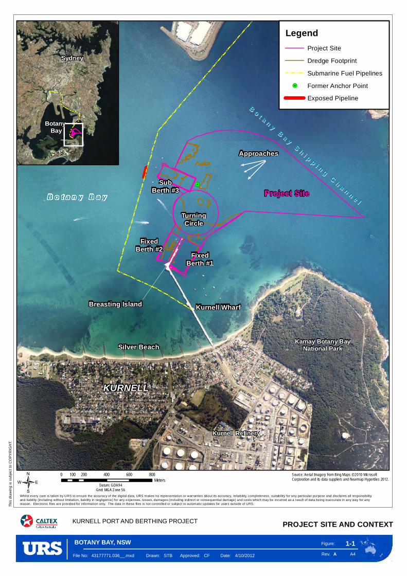
!.
Project SiteB o t a n y B a y
Kurnell Refinery
Kamay Botany BayNational Park
FixedBerth #2 Fixed
Berth #1
SubBerth #3
Kurnell Wharf
Silver Beach
KURNELL
TurningCircle
BB oo tt aa nn yy BB aa yy SS hh ii pp pp ii nn gg CC hh aa nn nn ee ll
Breasting Island
Approaches
Figure:
Rev. A4
1-1
KURNELL PORT AND BERTHING PROJECT
This
drawin
g is s
ubjec
t to C
OPYR
IGHT
.
/
A
0 200 400 600 800100Meters
Datum: GDA94Grid: MGA Zone 56
File No: 43177771.036__.mxd Drawn: STB Approved: CF Date: 4/10/2012
Whilst every care is taken by URS to ensure the accuracy of the digital data, URS makes no representation or warranties about its accuracy, reliability, completeness, suitability for any particular purpose and disclaims all responsibilityand liabili ty (including without limitation, liability in negligence) for any expenses, losses, damages (including indirect or consequential damage) and costs which may be incurred as a result of data being inaccurate in any way for any reason. Electronic fi les are provided for information only. The data in these files is not controlled or subject to automatic updates for users outside of URS.
Botany Bay
Sydney
PROJECT SITE AND CONTEXT
Source: Aerial Imagery from Bing Maps © 2010 Microsoft Corporation and its data suppliers and Nearmap Hypertiles 2012.
BOTANY BAY, NSW
LegendProject Site
Dredge Footprint
Submarine Fuel Pipelines
!. Former Anchor Point
Exposed Pipeline
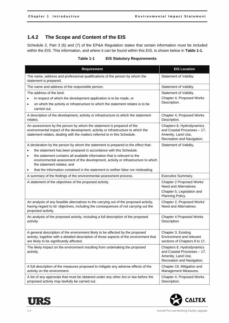
C h a p t e r 1 I n t r o d u c t i o n E n v i r o n m e n t a l I m p a c t S t a t e m e n t
1-4 Kurnell Port and Berthing Facility Upgrade
1.4.2 The Scope and Content of the EIS Schedule 2, Part 3 (6) and (7) of the EP&A Regulation states that certain information must be included within the EIS. This information, and where it can be found within this EIS, is shown below in Table 1-1.
Table 1-1 EIS Statutory Requirements
Requirement EIS Location
The name, address and professional qualifications of the person by whom the statement is prepared.
Statement of Validity.
The name and address of the responsible person. Statement of Validity.
The address of the land:
in respect of which the development application is to be made, or
on which the activity or infrastructure to which the statement relates is to be carried out.
Statement of Validity.
Chapter 4, Proposed Works Description.
A description of the development, activity or infrastructure to which the statement relates.
Chapter 4, Proposed Works Description.
An assessment by the person by whom the statement is prepared of the environmental impact of the development, activity or infrastructure to which the statement relates, dealing with the matters referred to in this Schedule.
Chapters 8, Hydrodynamics and Coastal Processes – 17, Amenity, Land Use, Recreation and Navigation.
A declaration by the person by whom the statement is prepared to the effect that:
the statement has been prepared in accordance with this Schedule;
the statement contains all available information that is relevant to the environmental assessment of the development, activity or infrastructure to which the statement relates; and
that the information contained in the statement is neither false nor misleading.
Statement of Validity.
A summary of the findings of the environmental assessment process. Executive Summary.
A statement of the objectives of the proposed activity. Chapter 2 Proposed Works’ Need and Alternatives.
Chapter 5, Legislation and Planning Policy.
An analysis of any feasible alternatives to the carrying out of the proposed activity, having regard to its’ objectives, including the consequences of not carrying out the proposed activity.
Chapter 2, Proposed Works’ Need and Alternatives.
An analysis of the proposed activity, including a full description of the proposed activity.
Chapter 4 Proposed Works Description.
A general description of the environment likely to be affected by the proposed activity, together with a detailed description of those aspects of the environment that are likely to be significantly affected.
Chapter 3, Existing Environment and relevant sections of Chapters 8 to 17.
The likely impact on the environment resulting from undertaking the proposed activity.
Chapters 8, Hydrodynamics and Coastal Processes – 17, Amenity, Land Use, Recreation and Navigation.
A full description of the measures proposed to mitigate any adverse effects of the activity on the environment.
Chapter 19, Mitigation and Management Measures.
A list of any approvals that must be obtained under any other Act or law before the proposed activity may lawfully be carried out.
Chapter 4, Proposed Works Description.
E n v i r o n m e n t a l I m p a c t S t a t e m e n t C h a p t e r 1 I n t r o d u c t i o n
Kurnell Port and Berthing Facility Upgrade 1-5
Requirement EIS Location
The reasons justifying the carrying out of the activity in the manner proposed, having regard to biophysical, economic and social considerations, including the principles of ecologically sustainable development (ESD) relating to:
the adoption of precaution in instances of uncertainty (the precautionary principle);
the preservation of the environment as a resource between generations (inter-generational equity);
the conservation of biological diversity and ecological integrity; and
the improved valuation of environmental assets and services based mechanisms such as the polluter pays principle, lifecycle costing and establishing environmental goals.
Chapter 20, Proposed Works Evaluation and Justification.
1.4.3 Environmental Assessment Requirements The EA has been conducted, and the EIS prepared, in accordance with the requirements of the EP&A Regulation and specific environmental assessment requirements provided by the NSW DP&I in its correspondence dated 9 August 2012.
The EA requirements, referred to as Director General’s Requirements (DGRs), are provided in Technical Appendix A. This technical appendix also contains a table cross-referencing the DGRs and where they have been addressed in this EIS.
The DGRs identified both general requirements and key issues to be addressed in the EIS. The key issues comprise:
hydrological impacts relating to changes in hydrodynamic character and coastal processes resulting from the proposed works;
issues relating to spoil and contamination, with specific reference to the characterisation, management and disposal of the dredged sediments;
impacts on water quality, including sediment suspension, dispersion and settlement;
impacts on flora and fauna, with note of the range of sensitive ecological resources and receptors located close to the proposed works;
the issues of Aboriginal and historic heritage, with note of the potential for maritime heritage impacts;
general construction issues, with reference to noise, vibration, hazards, risks, effects on Port Botany operations, and air quality; and
general operational issues as relevant, including noise, air quality, hazards, risks and the operation of Port Botany.
These key issues have been addressed through targeted detailed assessments and described in a number of specific EIS chapters and technical reports. A breakdown of the DGRs and where they have been included in this EIS is provided in Chapter 6, Consultation.
C h a p t e r 1 I n t r o d u c t i o n E n v i r o n m e n t a l I m p a c t S t a t e m e n t
1-6 Kurnell Port and Berthing Facility Upgrade
1.5 EIS Exhibition and Determination This EIS document will be placed on public exhibition in accordance with Section 83 of the EP&A Regulation pursuant to Section 89F of the EP&A Act, which relates to the process of public participation.
Subsequent to its exhibition, copies of all valid submissions covering issues raised by statutory agencies, environmental bodies, members of the public, and other stakeholders would be provided to Caltex and uploaded on the NSW DP&I website. Caltex would review the submissions and provide consideration and response to any issues that are raised.
The Director-General will then prepare an Assessment Report, which considers the findings of the EIS against meeting the DGRs and the issues submitted to the NSW DP&I. Determination for State Significant Development (SSD) is carried out under powers delegated from the Minister for Planning and Infrastructure. Current policy dictates that when a political donation has been made by a proponent powers of determination are delegated to the Planning Assessment Commission (PAC). As Caltex has made such a donation, the Assessment Report would be provided to the PAC who would then determine the development application.
1.6 EIS Structure This EIS is presented in two volumes.
Volume One: EIS Main Report
Volume 1 consists of the chapters below.
Executive Summary The executive summary provides a non-technical assessment of the proposed works.
Introduction Chapter 1 introduces the proposed works, explains their overall objective, describes the statutory basis for and scope of the EA process and outlines the structure adopted in the EIS.
Proposed Works Need and Alternatives
Chapter 2 describes the need for the proposed works and the alternatives considered during the identification of the preferred method and approach to undertaking the proposed works. It outlines the factors leading to the decision to increase the navigation depth and upgrade the berthing infrastructure over not undertaking the works at all (the do nothing alternative), the alternative methods considered, and the alternatives to managing and disposing of the dredged sediment.
Existing Environment Chapter 3 provides an overview of the existing environment in which the proposed works would take place.
Proposed Works Description
Chapter 4 describes the key components, activities and characteristics associated with the proposed works.
Legislation and Planning Policy
Chapter 5 includes the relevant Commonwealth and State legislation and planning policy and identifies licences and approvals required to enable the proposed works to proceed.
E n v i r o n m e n t a l I m p a c t S t a t e m e n t C h a p t e r 1 I n t r o d u c t i o n
Kurnell Port and Berthing Facility Upgrade 1-7
Consultation Chapter 6 outlines the consultation process adopted throughout the EA
process.
Scope and Approach
to Assessment
Chapter 7 explains the scope of the EIS under the environmental aspect
headings set out to consider the key issues raised in the DGRs (see
Section 1.4.3).
Environmental
Assessment
Chapters 8-17 report the findings of the detailed environmental assessments
undertaken to support the EIS. The chapters also identify the predicted impacts
of the project with the inclusion of mitigation. To aid the understanding and
relationship between the various detailed environmental assessments, these
chapters are presented in a standardised format that is described in Chapter 7,
with the exception of Chapter 15, Waste and Resource Management.
Cumulative
Assessment
Chapter 18 describes the interactions of predicted impacts on the existing
environment and any associated cumulative effects. It also considers the
interaction of any approved development that would be undertaken, constructed,
operated or decommissioned at the same time as the proposed works.
Mitigation and
Management
Measures
Chapter 19 provides a summary of the mitigation and management measures
for the proposed works.
Proposed Works
Evaluation and
Justification
Chapter 20 summarises the impacts and effects of the proposed works in the
context of the environmental assessment requirements and the principles of
ecologically sustainable development (ESD).
Volume Two: Technical Appendices
Volume 2 comprises the various technical appendices referred to in Volume 1. The technical appendices
contain relevant supplementary information and data used to undertake the detailed environmental
assessments reported in Chapters 7-18. In total there are 28 technical appendices (A-O)1. Specialist
reports on the physical environment, hydrodynamic and coastal processes, sediment and water quality,
noise, air quality, heritage, and hazards and risks are included as technical appendices.
1 Including Technical Appendices D1-D3 and E1-E10.
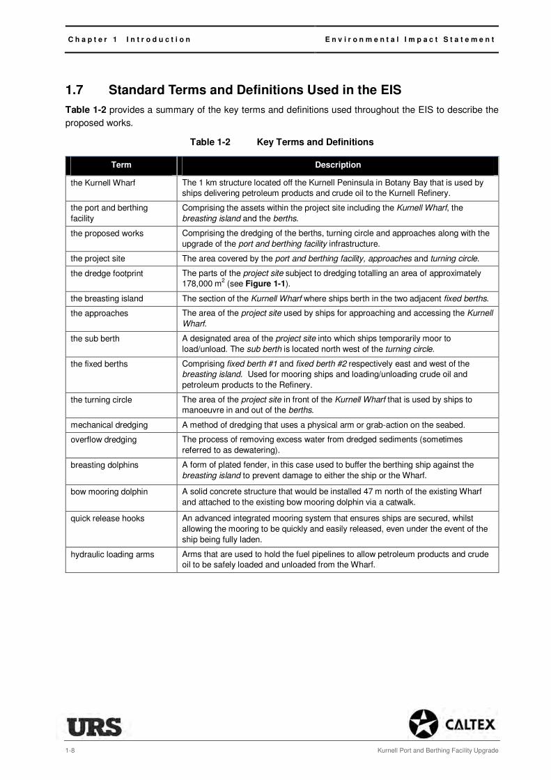
C h a p t e r 1 I n t r o d u c t i o n E n v i r o n m e n t a l I m p a c t S t a t e m e n t
1-8 Kurnell Port and Berthing Facility Upgrade
1.7 Standard Terms and Definitions Used in the EIS
Table 1-2 provides a summary of the key terms and definitions used throughout the EIS to describe the
proposed works.
Table 1-2 Key Terms and Definitions
Term Description
the Kurnell Wharf The 1 km structure located off the Kurnell Peninsula in Botany Bay that is used by
ships delivering petroleum products and crude oil to the Kurnell Refinery.
the port and berthing
facility
Comprising the assets within the project site including the Kurnell Wharf, the
breasting island and the berths.
the proposed works Comprising the dredging of the berths, turning circle and approaches along with the
upgrade of the port and berthing facility infrastructure.
the project site The area covered by the port and berthing facility, approaches and turning circle.
the dredge footprint The parts of the project site subject to dredging totalling an area of approximately
178,000 m2 (see Figure 1-1).
the breasting island The section of the Kurnell Wharf where ships berth in the two adjacent fixed berths.
the approaches The area of the project site used by ships for approaching and accessing the Kurnell
Wharf.
the sub berth A designated area of the project site into which ships temporarily moor to
load/unload. The sub berth is located north west of the turning circle.
the fixed berths Comprising fixed berth #1 and fixed berth #2 respectively east and west of the
breasting island. Used for mooring ships and loading/unloading crude oil and
petroleum products to the Refinery.
the turning circle The area of the project site in front of the Kurnell Wharf that is used by ships to
manoeuvre in and out of the berths.
mechanical dredging A method of dredging that uses a physical arm or grab-action on the seabed.
overflow dredging The process of removing excess water from dredged sediments (sometimes
referred to as dewatering).
breasting dolphins A form of plated fender, in this case used to buffer the berthing ship against the
breasting island to prevent damage to either the ship or the Wharf.
bow mooring dolphin A solid concrete structure that would be installed 47 m north of the existing Wharf
and attached to the existing bow mooring dolphin via a catwalk.
quick release hooks An advanced integrated mooring system that ensures ships are secured, whilst
allowing the mooring to be quickly and easily released, even under the event of the
ship being fully laden.
hydraulic loading arms Arms that are used to hold the fuel pipelines to allow petroleum products and crude
oil to be safely loaded and unloaded from the Wharf.

E n v i r o n m e n t a l I m p a c t S t a t e m e n t C h a p t e r 2 P r o p o s e d W o r k s N e e d a n d A l t e r n a t i v e s
Kurnell Port and Berthing Facility Upgrade 2-1
2 Proposed Works Need and Alternatives
2.1 Introduction Under the EP&A Regulation there is a requirement for an environmental impact statement (EIS) to set out the objectives of the proposed works, whilst considering how these objectives could be feasibly achieved through alternative means other than described in Chapter 4, Proposed Works Description. This includes the consequences of not carrying out the proposed works (the ‘no action’ alternative). The following chapter describes the needs case for the proposed works, the objectives of the proposed works and the various alternatives that have been considered.
2.2 Strategic Need Kurnell Refinery has the capacity to produce 135,000 barrels of refined petroleum product per day (approximately 21.5 million litres per day or 7.8 billion litres per annum). This production is supplemented by 650 million litres of refined petroleum product imports per annum.
The Refinery is an important processing and distribution point. It supplies approximately 40-50% of the overall fuel supplied to New South Wales (NSW) and Australian Capital Territory (ACT) markets. This includes a significant amount of transport fuel. The Refinery also supplies a range of other fuel and speciality petroleum products to domestic and international markets whilst being a leading supplier of jet fuel to Sydney (Kingsford-Smith) Airport.
In July 2012 following an extensive review, Caltex announced that it would cease refining operations at Kurnell in mid-2014 and convert the site to a major import terminal. This would allow Caltex to continue its role as the major supplier of refined fuels to NSW and ACT markets.
As a storage and distribution facility Kurnell would continue to be a critical link in the transport fuel supply chain thereby meeting demand at Caltex’s current market share. It would also be the intention for Caltex to participate in the expected growth in demand for petroleum products in NSW. This growth is anticipated to be approximately 4-5% per annum. The Refinery’s feedstock of crude oil and the imported refined petroleum products are supplied entirely by ship. The Kurnell Refinery is reliant on its three marine berths for the inbound movement of crude oil and imported product and the outbound movement of some of its finished product. As an import terminal, Kurnell would be totally reliant on its berths for the inbound movement of the finished product that would be distributed to the transport, aviation, mining, agriculture, industrial and commercial sectors of the NSW and the ACT economies.
It is important to note that whether as a refinery or an import terminal, Kurnell is at the hub of Caltex’s entire supply chain for NSW and the ACT. Radiating out from this hub is the extensive network of pipelines that Caltex has invested in to supply bulk fuel to strategically located terminals (fuel distribution
centres) at Banksmeadow (servicing much of Sydney and southern NSW), Silverwater (servicing western Sydney and NSW) and Newcastle (servicing the Hunter region and Northern NSW). These terminals do not have the capability to import finished product by ship and are not capable of being converted to import
facilities in the future. They are, and would continue to be, reliant on Kurnell as the principal fuel supply source.
The nearest alternative import centres are Caltex’s facilities in Brisbane and Melbourne, but they would both require extensive capital investment to increase import capability. Even then, distribution from there
to the NSW market would require an enormous and unsustainable increase in tanker truck traffic both interstate and around the Banksmeadow, Silverwater and Newcastle terminals.

C h a p t e r 2 P r o p o s e d W o r k s N e e d a n d A l t e r n a t i v e s E n v i r o n m e n t a l I m p a c t S t a t e m e n t
2-2 Kurnell Port and Berthing Facility Upgrade
2.3 Project Need Ten to thirteen ships arrive at the Wharf each month to discharge crude oil from large vessels (length >= 245 m) at the sub-berth for use as refinery feedstock, or in a minority of cases, load by-products in smaller vessels (length of 180-200 m) at the fixed berths for exports or interstate use. The current design and configuration of the three berths limits the size of ships that can be received at the berths. The sub berth is currently limited to only receive larger ships (length >= 245m), whilst the fixed berths are limited to only receive smaller ships (length of 180-200 m). The proposed works would allow the berthing facility to receive various ship sizes (length of 180-245 m) into the three berths, with the ship sizes being no larger than those currently received at the Kurnell Wharf.
An additional ongoing issue is the ability for these ships to safely approach and access the port and berthing facility due to the build-up of seabed sediments across the project site. Caltex must increase the navigable depth to ensure the continued safe use of the facility. In addition, Caltex would seek to increase the depth and size of its two fixed berths, which have not been dredged since being formed, whilst upgrading the berthing equipment at one of the fixed berths and the sub berth, as well as implementing a number of additional structural improvements and refinements. As such, a major focus of the proposed works would be to maintain continued operations and extend the operational life of the Kurnell port and berthing facility.
2.4 Objectives
2.4.1 Company Objective Caltex is the largest marketer of petroleum products and the number-one convenience retailer in Australia. The cornerstone of its business is to provide safe and reliable supply for all its customers.
Caltex continues to build its position as Australia’s leading supplier of petroleum fuels by further investment in its supply chain and marketing assets. The Kurnell port and berthing facility is a key part of this supply chain. Extending the life of an existing asset provides assurance of supply to the market.
2.4.2 Proposed Works’ Objectives The objectives of the proposed works would be to: .
maintain the current shipping capability and access to the port and berthing facility and optimise shipping economics;
improve the capability of the port and berthing facility to meet future demands in NSW and the ACT;
reduce supply costs, and improve Caltex’s business competitiveness; and
bring the port and berthing facility up to current compliance standards1.
1 Oil Companies International Marine Forum (OCIMF) Guidelines, 2010

E n v i r o n m e n t a l I m p a c t S t a t e m e n t C h a p t e r 2 P r o p o s e d W o r k s N e e d a n d A l t e r n a t i v e s
Kurnell Port and Berthing Facility Upgrade 2-3
The proposed works would also aim to achieve the following specific objectives for the berths:
sub berth:
– restore the depth back to the original design depth;
– upgrade the berthing arrangement and configuration to comply with design code changes implemented post 20052; and
– allow a range of different-sized ships into the berth.
fixed berths:
– deepen, lengthen and widen the berths;
– upgrade the infrastructure on fixed berth #1 to accommodate larger ships than this berth has been able to accommodate previously; and
– install a loading and mooring system with enhanced safety features2.
The wider objective of improving the sub berth and fixed berths would bring operational efficiency to the port and berthing facility. Following the proposed works shipping numbers would indicatively reduce by
40% by 2020 for the reasons discussed in Section 4.6.4. In addition, Caltex would improve the safety of berthing for ships, which would be achieved by allowing larger capacity ships to berth at the fixed berth than at present, hence the proposed increase in length and width.
This would result in fewer restrictions in unloading larger ships during heavy seas, as they could safely berth against the Wharf. Conversely, the reconfiguration of the sub berth improves flexibility as smaller
sized ships (length of 185 m over 245 m ships) would be able to moor in this location. Collectively this would provide greater supply reliability to market, which ultimately would bring a benefit to the end user.
In summary, the overall objective of the proposed works would be to:
allow safer mooring;
introduce greater operational flexibility;
reduce overall shipping numbers; and
retain the use of the facility by the same size (capacity) of ship as presently uses the facility, albeit in a different and more flexible configuration.
2.5 Alternatives
2.5.1 Introduction Consideration has been given to the alternative actions or methods that may be put in place to meet the needs and objectives of the proposed works. These include:
take no action;
alternative supply of refined product to meet demand;
2 Achieved through having a hydraulic over manual loading system

C h a p t e r 2 P r o p o s e d W o r k s N e e d a n d A l t e r n a t i v e s E n v i r o n m e n t a l I m p a c t S t a t e m e n t
2-4 Kurnell Port and Berthing Facility Upgrade
alternative methods of disposal of dredge spoil;
alternative working methods; and
alternative programming and timing.
2.5.2 Alternative Approaches
Take-No Action Alternative
The proposed works are limited to the need to dredge the project site and upgrade the port and berthing facility to ensure continued access by ship.
The alternative of taking no action would result in a continuing build-up of sediment across the project site. This would lead to a need to reduce the size of ships accessing the port and berthing facility as the draft depth clearance continues to reduce. This would increase the required frequency of shipments to an infeasible level, which in turn could impact the reliability of supply. This would affect the efficiency and cost of fuel distribution within NSW and the ACT. It would also likely have a detrimental effect on end-user costs.
This alternative would not meet the strategic need or objectives for the proposed works and has therefore not been considered further.
New Port and Berthing Facilities
One possible alternative would be to construct an entirely new import and export facility at a location within Botany Bay or along the Kurnell Peninsula in order to meet the objectives of the proposed works.
Alternatives relating to construction of a new port and berthing facility were discounted on prohibitive economic and environmental grounds as the impacts of a new facility and decommissioning or downgrading the existing facility were considered to be far more significant than extending the life of an existing asset. As such, these options were not investigated further.
Importing Product from an Alternative Location
A further option would be to import finished product from the bulk liquid berth terminal located within Port Botany, and then pipe finished products to the Kurnell Refinery. This would require the construction of an additional set of subsea fuel pipelines across Botany Bay. Whilst a number of pipelines and cables have been successfully laid across the Bay, this alternative has been discounted due to the potential environmental impacts, congestion at the bulk liquid terminal (even after the intended commissioning of a second berth), and the high capital cost.
Although alternative import and export sites could be available in the area, the potential environmental and economic constraints on development of these options have led to them being discounted from further investigation.
Upgrading the Existing Port and Berthing Facility
The preferred option to meet the strategic need and proposed works’ objectives is to upgrade the existing port and berthing facility. This alternative involves extending the life of an existing and functional asset that performs within the constraints of existing environmental controls, permits, licences and registrations, and provides the best economic returns for Caltex.

E n v i r o n m e n t a l I m p a c t S t a t e m e n t C h a p t e r 2 P r o p o s e d W o r k s N e e d a n d A l t e r n a t i v e s
Kurnell Port and Berthing Facility Upgrade 2-5
This option is the most economically viable option on balance of the costs and benefits to the project. It is also likely to have a lower environmental impact than constructing a new port and berthing facility or new subsea pipelines. This option meets the strategic need and objectives of the proposed works and has therefore been further assessed.
2.5.3 Alternative Disposal Methods
Introduction
The proposed works aim to dispose of the dredged sediment at sea. Alternatives to the proposed option for offshore sea dumping would be either onshore disposal or the (partial) reuse of the dredged sediments within Botany Bay. These alternatives have been considered in detail as part of the analysis and assessment process of obtaining a Sea Dumping Permit (SDP) from the Commonwealth Government (see Chapter 9, Spoil and Contamination).
Onshore Disposal
The findings of the SDP analysis and assessment process (see Technical Appendix D1 and D2) has demonstrated that whilst the dredged sediment would be suitable for onshore disposal, the elevated levels of tributyltin (TBT) present at certain locations within the project site would require special controls to be put in place to bring these sediments ashore.
Onshore disposal would present two further complications. The first is the need to dewater the dredged sediments (and manage this water), and the second is the need to treat the dredged sediments prior to disposal due to their acid sulfate characteristics.
Onshore disposal would also require the dredged sediments be transferred by truck to a relevant treatment/storage site. The landfill transfer point from ship to truck would be along Prince Charles Parade. This would increase the number of truck movements through the Kurnell Peninsula during the proposed works, and would extend the overall program.
For these reasons, backed by opinion obtained from the Department of Primary Industry (Fisheries) and the NSW Environment Protection Authority (EPA), onshore disposal has been discounted.
Reuse of Dredged Sediments
The possibility of reusing certain of the dredged sediments within Botany Bay has been reviewed as part of the analysis and assessment undertaken to support obtaining the SDP.
This review confirmed that 7,800 m3 of the dredge sediments could be beneficially reused. This is due to it being assessed as not exceeding the water and sediment quality limits set within the Commonwealth National Assessment Guidelines for Dredging 2009 and therefore being classified as uncontaminated.
The proposed works include an objective to reuse approximately 6,000 m3 of that material (see Section 4.4.9). The alternative would be full disposal. Environmentally and economically some level of reuse would be considered beneficial as it would limit transportation and associated costs. It would also provide a reasonable opportunity for finding solutions to managing two long-standing issues, namely infilling an exposed anchor point and covering two exposed sections of the subsea fuel pipelines (see Section 4.4.9).
Dredged sediment that cannot be reused would be disposed of at the Sydney Offshore Spoil Ground, a dedicated disposal ground set up by the Commonwealth approximately 25 km from Botany Bay.

C h a p t e r 2 P r o p o s e d W o r k s N e e d a n d A l t e r n a t i v e s E n v i r o n m e n t a l I m p a c t S t a t e m e n t
2-6 Kurnell Port and Berthing Facility Upgrade
2.5.4 Alternative Working Methods
Dredging Methods
Alternative methods of dredging are chosen based on the nature, scale and composition of the sediments that need to be dredged, the local environmental conditions, and the need to work next to marine structures or within shallow waters.
Two methods of dredging were considered in developing the proposal, namely hydraulic dredging and mechanical dredging. The final choice of dredging method considered the above factors, and also took into account the availability of suitable dredging equipment within Australian waters.
The existence of notable peat deposits within the fixed berths (see Chapter 9, Spoil and Contamination) is not conducive to the use of hydraulic dredging, which cannot effectively work, cut and lift such sediments. Better precision can be obtained through using a mechanical method therefore ensuring accuracy and protection around the Kurnell Wharf and associated subsea infrastructure (i.e. subsea pipelines, moorings, anchors, chains, wires etc.).
The use of the mechanical backhoe method (the promoted alternative) would cause some disturbance of sediments when working the seabed. Sediment disturbance would also be caused by deploying and removing its anchoring ‘spuds’. Given its accuracy however, this method is considered far less impacting than the hydraulic alternatives as it would limit the extent of sediment dispersion in the marine environment. In turn, the backhoe dredger would minimise turbidity, sediment deposition and limit impacts on water quality, toxicity and bioaccumulation compared to the alternative hydraulic methods.
One disadvantage of the mechanical backhoe method is the need to lift materials through the water column, which can release sediments, albeit in small quantities, due to the use of a closed bucket. There is also a degree of water-spilling that occurs when lifting the material onto the hopper barge. These impacts however can be managed reasonably effectively through controlling lifting and transfer operations.
The main alternative to the proposed backhoe method would be the use of a grab dredger. Grab dredging methods are broadly similar to backhoe methods however are less precise and require a longer construction program; potentially increasing the overall environmental impact of the proposed works. Use of a grab dredger was therefore discounted.
Of the two feasible hydraulic methods, the cutter suction method would see substantially more water being removed during dredging over the backhoe method. In order to make using this method operationally efficient, a large volume of water would need to be returned to the Bay (termed overflow dredging). This process of overflow dredging releases sediment back into the marine environment and causes turbidity. Impacts from cutter suction methods can be minimised by pumping the material directly to the disposal or reuse areas, however this option is not economically feasible for the proposed works.
The other hydraulic method of trailing suction hopper dredging creates the most disturbance to the seabed through its abrasive suction motion. The trailing suction method can make use of a ‘green valve’ to limit turbidity, however the water volumes associated with this method are substantial compared with the backhoe method, requiring additional overflow.
In addition, hydraulic alternatives were discounted after considering the economics of mobilising a hydraulic dredger to undertake the proposed works, which would have required significant mobilisation costs due to the lack of availability local to the proposed works.
E n v i r o n m e n t a l I m p a c t S t a t e m e n t C h a p t e r 2 P r o p o s e d W o r k s N e e d a n d A l t e r n a t i v e s
Kurnell Port and Berthing Facility Upgrade 2-7
It was concluded that the practicality and economics of hydraulic dredging as a full or partial alternative to mechanical dredging would not be appropriate for the proposed works. Therefore mechanical dredging, specifically backhoe dredging, was chosen as the preferred dredging method.
Alternatives to Controlling Sediment Dispersion
There are two feasible methods to control sediment dispersion; either actively through controlling the dredging, or passively through the use of controls such as silt curtains.
As noted in the associated technical chapter (see Chapter 10, Water and Sediment Quality) the sediment generated through the proposed works using the backhoe dredging method would only affect a small area local to the dredging activity. For this reason there would be no requirement to manage sediment dispersion either actively or passively.
However under the precautionary principle (which forms one of the principles of Ecologically Sustainable Development (ESD)), feasible and reasonable controls pertaining to environmental best practice could be implemented.
Volunteering the use of silt curtains has been considered as part of the works execution, however this was discounted for a number of practical reasons. Silt curtains remain most effective in still, calm, shallow waters. As an active berthing facility the ability to curtain around the dredger, which would be routinely moving to accommodate berthing shipping movements, would be impractical. The only other alternative thereafter would be to curtain outside of the port and berthing facility. This would require a considerable length for the curtain to be effective (greater than 200 m). The practical management of such a large curtain in what is a dynamic, energetic and mobile area of Botany Bay (which is exposed to heavy seas and storm surges) would also be impractical. It would require the curtain to be chained and weighted to the seabed, itself presenting issues environmentally. Also, the curtain would have a real risk of failing under pressure. Not only would this defeat its purpose, but lost curtains present risks both environmentally and ecologically from the perspective of the entrainment of fauna, as well to shipping from entanglement.
The alternative active method would be to further limit on, or fully restrict the use of, overflow dredging (returning excess water to Botany Bay) and instead transporting the water for disposal offshore.
As noted within the modelling simulation scenarios conducted by Cardno (see Technical Appendix C) the process of overflow dredging is the significant factor that causes sediment dispersion in Botany Bay. Placing a restriction on overflow dredging would provide near instantaneous results that would be comparable to the installation and use of a silt curtain. For this reason this alternative has been promoted in the EIS. Offshore, the modelling undertaken by Worley Parsons (see Technical Appendix D1 and D2) has confirmed that returning overflow water and sediment within the more dispersive environment of the Sydney Offshore Spoil Ground would provide sufficient dilution for there to be no exceedance of relevant water or sediment quality criteria governing the proposed work (see Chapter 5, Legislation and Planning Policy Context).
Alternative Piling Methods
The method of piling is partially dictated by the type of sediment, the depth and size (diameter) of pile and the ultimate loads the piles would have to bear.
The piles needed to support the proposed works would need to be sunk to depths of 25-30 m below the seabed. They would be founded in a stiff clay layer present at this depth (see Technical Appendix L).
To achieve this several methods of piling have been considered.
C h a p t e r 2 P r o p o s e d W o r k s N e e d a n d A l t e r n a t i v e s E n v i r o n m e n t a l I m p a c t S t a t e m e n t
2-8 Kurnell Port and Berthing Facility Upgrade
The principle method is vibratory piling. Piles are installed via a vibrating hammer mounted on the head of a pile. The method basically ‘shakes’ the pile in to the seabed. It is an excellent (lower noise) alternative that works in less cohesive sediments such as the sands near the surface, as the vibrations liquefy the sand in the vicinity of the pile allowing it to sink under its own mass. However, it encounters problems in more cohesive materials (such as clay or at depth in sand) where there is considerable resistance preventing the pile from easily moving through such a medium.
A second alternative would be hydraulic hammer piling, which is used to drive piles in to the ground. As a very traditional form of piling it produces a typical repetitive hammering noise. It is more conducive to piling in cohesive and resistant materials. It is an inefficient method as it is time consuming compared to more modern alternatives.
Bore/drill piles are another approach, which again works until the point of refusal. It is based on a driven method of piling using a drill. This results in a plug of material forming inside the pile, which would need clearing in order for the pile to advance. This method has not been promoted given the need to dispose and store waste materials through the creation of the drilling plugs.
Spun or screw piles use a cutting method, where a head is placed on the bottom of a tubular steel pile and the pile is advanced by rotating and cutting in to the sediments. This method has limited efficacy in cohesive materials. Also, there is a technical limitation of using this method for the larger diameter piles required to support the works, therefore precluding this as a feasible option.
Water jet piling uses carefully directed and pressurised water flows to ‘erode’ material at the toe of the pile as it is advanced. This reduces friction and in effect supplements vibratory or hydraulic hammer methods. This method causes a loss in friction around the pile. For large piles, as would be installed, such a loss of friction would be considered dangerous given the overall loads (i.e. some friction makes piling safer). Additionally, the water runoff from the hoses has the potential to generate notable erosion and turbidity around the pile head, and would be subject to additional environmental controls.
The jacked pile method provides an alternative of installing piles using a static jacking force delivered through a hydraulic ram. The hydraulic ram is placed against a known structure with the required capacity to force the pile in to the sediments. Although feasible close to the Wharf in many of the locations, the distance is too far for this to be a feasible method.
Bored in-situ cast piling is formed where a hole is drilled through a casing prior to installation of reinforcement and an in-situ concrete pour. This method is simply not practical where steel piles are to be used (as is the proposal for these works).
Whilst a number of alternatives have been considered, the only remaining practical and feasible options are the vibratory and hydraulic hammer piling methods. Both are favourable for working in these specific sediments for the reasons discussed above. For this reason it is proposed that vibratory piling is used within the upper soft sediments backed by hammer piling the last few metres to bed the pile in to the clay horizon.
Placing the Reused Sediments
The reuse (and placement) of sediments can be undertaken by a number of methods. The proposed method would be to allow the dredged sediments to settle over either the exposed pipeline or within the anchor point (see Section 4.4.9). The principal alternative would be to use a method where the sediment would be actively pumped from the dredgers to the reuse location to then be discharged close to the seabed.

E n v i r o n m e n t a l I m p a c t S t a t e m e n t C h a p t e r 2 P r o p o s e d W o r k s N e e d a n d A l t e r n a t i v e s
Kurnell Port and Berthing Facility Upgrade 2-9
The active pumping method is warranted in instances where considerable sediment volumes are being transferred from one area to another, and is economical where it is used over reasonable distances. As the proposed works would reuse a comparatively small quantity of sediment close to the point of dredging, the economics of employing the active pumping method would be less favourable than the proposed settlement method.
The impact of the proposed method has been assessed and compared to alternative techniques. The conclusion of the assessment is that this method would not lead to a significant residual effect on the receiving environment, provided the mitigation and management measures set out in Chapters 9, Spoil and Contamination and 10, Water and Sediment Quality are implemented.
2.5.5 Berthing Equipment The proposed upgrade of the berthing equipment is designed to comply with a range of Australian, British and European Standards along with the Oil Companies International Marine Forum (OCIMF) Guidelines, 2010. This limits the alternatives available to achieve the proposed works’ objectives.
Nevertheless, there are possible localised alternative layout and design configurations available to Caltex to berth and moor the ships, all of which achieve the same objective with broadly comparable environmental impacts. All reasonable options would however require additional expansion of the fixed berths and the need to pile into the seabed.
2.5.6 Alternative Programing and Timing
Proposed Works Program
The proposed program for the works spans two-years (see Table 4-4). Caltex has made every effort to shorten the construction program, including examining parallel instead of sequential construction activities. The former would require closure of the ports and berthing facility for an extended period. This would prevent import and export, requiring Caltex to develop alternatives, such as total reliance on interstate road transport to supply NSW and the ACT with transport fuels over this period. This would require a significant number of trucks to offset the closure. It would also have a substantial effect on supply economics. Caltex therefore believes the proposed program provides the required balance of executing each stage of the works in as short and reasonable timescale as possible, whilst allowing the continued operation of the port and berthing facility.
Proposed Works Dredging Program
The proposed timing of the program of works would be dictated by the availability of a suitable dredger and the need to minimise operational disruption. The long lead time to secure a dredger has resulted in a program that would start in late autumn/early winter 2013, lasting approximately 23 weeks.
The time of year in which the works are proposed has an impact on the tidal extremes under which the works would be conducted. The advantages and disadvantages present as a result of selecting this time of year to conduct the work have been considered as part of the EIS. This has shown that the proposed dredging would not result in a significant adverse residual effect on the resources, receptors and values that form the existing environment providing the appropriate mitigation and management measures are implemented (see Chapter 19, Mitigation and Management Measures).

C h a p t e r 2 P r o p o s e d W o r k s N e e d a n d A l t e r n a t i v e s E n v i r o n m e n t a l I m p a c t S t a t e m e n t
2-10 Kurnell Port and Berthing Facility Upgrade
Working Hours
The majority of the works would be constrained to the standard hours prescribed in the Interim Construction Noise Guidelines, 2009. The exception would be the upgrade to the sub berth, which would take place between 0700 and 1800 seven-days per week and the dredging, which would take place continuously except for breaks of 2 hours each day to allow for crew changeovers and up to 1 day per week to allow for scheduled maintenance. In addition, there would be other periods where dredging would stop to accommodate shipping movements in and out of the berth. Ideally, the dredger would simply relocate to another area of the dredge footprint in such instances.
This proposed program is considered viable given that the port and berthing facility currently operates continuously. Under this approach it would take approximately 23 weeks to complete the proposed dredging works, allowing for the ongoing operation of the port and berthing facility. Should the dredging be restricted to standard working hours it is anticipated that the proposed works would take 40-50 weeks to complete and incur an additional cost of approximately $45 million. Such an increase (more than double the original cost) would be due to the need to hire the dredger for a longer period of time and an additional incurred (stand-down) cost applied by the dredging contractor for not dredging continuously over this period.
The time extension would pose a significant risk on the ability to complete the works prior to Kurnell Refinery’s proposed conversion to a terminal. This, in turn, would greatly jeopardise Caltex’s ability to reliably supply fuel to the NSW and the ACT markets (including the airport) during such an extended period. This could potentially lead to a period of fuel shortages along with the price impact of having to use high-cost supply alternatives, such as interstate trucking. This conclusion is further supported by the fact that the supply and distribution network (generated by other terminals and the available trucking fleet) is at capacity and cannot increase its throughput from other sources to mitigate restrictions at Kurnell.
Environmentally, there would be broadly no difference to the impact of the proposed dredging works whether a short or long dredging program was undertaken. Whilst the longer dredging program would result in sediment plumes being generated over a longer period (which aesthetically may be less appealing), it would possibly reduce turbidity as there would be settlement over the night period when dredging was not taking place. Conversely, dredging continuously would not cause a significant impact given the scale of the works and the dredged volumes involved (see Chapter 10, Water and Sediment Quality). Also, the extent of overall sediment depth and deposition would be broadly similar independent of the duration of the proposed works.
As the works would take place largely within an area restricted from recreational use, the longer program would not result in greater recreational disruption; with the exception of constraining ship movements to the disposal ground to being undertaken only during the daytime. This may result in greater shipping pressures on the shipping channel, however the impact would be negligible. Whilst it is accepted that night works are not generally favoured, the action of a dredger working offshore in the context of the scale of the continually operating port and berthing facility is unlikely to create additional visual impacts or the potential for ecological impacts due to the use of night lighting (see Chapter 11, Ecology).
In terms of noise impacts the modelling has shown that even when dredging outside of the standard hours that there would be no exceedance of the noise management levels set for the identified sensitive receptor close to the proposed works (see Chapter 13, Noise).
E n v i r o n m e n t a l I m p a c t S t a t e m e n t C h a p t e r 2 P r o p o s e d W o r k s N e e d a n d A l t e r n a t i v e s
Kurnell Port and Berthing Facility Upgrade 2-11
2.6 Conclusions The long-term continued use of the port and berthing facility as the sole point for import could only be feasibly achieved through undertaking the proposed works.
Caltex has considered a number of alternative means by which the proposed works could be undertaken to achieve the needs case, and project objectives and has selected a preferred method based on a balance of economic, environmental and social considerations.
Importantly this balance provides a feasible solution with no significant environmental effects provided necessary mitigation and management measures are implemented.
The rigorous assessment of a broad range of options, and the considered selection of the proposed works and method, has been driven by Caltex’s desire to continue to remain environmentally and socially responsible. Regulatory and community consultation, alongside various technical studies, have helped finalise the method for the proposed works, including its timing and execution.

E n v i r o n m e n t a l I m p a c t S t a t e m e n t C h a p t e r 3 E x i s t i n g E n v i r o n m e n t
Kurnell Port and Berthing Facility Upgrade 3-1
3 Existing Environment
3.1 Introduction The following chapter provides a general description of the environment that could potentially be affected by the proposed works.
3.2 Environmental Context Botany Bay is a shallow bay covering 4,600 hectares located approximately 10 km south of the Sydney City Central Business District (CBD). It is used to access Sydney’s main commercial port (Port Botany).
There are a number of competing economic, recreational and ecological interests related to the aquatic
environment within the Bay. These include aquatic resource management, primary industries (such as aquaculture), and recreational interests (such as fishing, diving and sailing). The area also holds cultural and spiritual values for Aboriginal groups.
The Bay is located within the Sydney Metropolitan Catchment Management Area (SMCMA) and is
designated a Special Port Area (Sydney Ports, 2012). As such, there are a number of controls regarding the management of its waters and waterside lands.
3.3 The Marine Environment
3.3.1 Background Botany Bay is a wide, shallow estuary exposed to winds from all directions and waves from the adjacent high-energy coastal zone. Waves and currents determine the sediment erosion, deposition and transport
patterns of the Bay and therefore the ultimate fate of sediments. Previous developments, most notably in northern Botany Bay, have modified the foreshores and substantially changed the local hydrodynamics. Any future changes to the Bay’s bathymetry (depth) and shoreline could further affect hydrodynamic
conditions and the transport of sediment. Ultimately these affects could impact on the stability of the beaches and infrastructure, whilst having secondary ecological impacts.
3.3.2 Tides
Botany Bay has a mean tide period of 12.4 hours. Generally, the tidal cycle is semi-diurnal (with two high and low tides occurring within the tide period). Tidal amplitude varies fortnightly on a high and low range
tidal cycle. The maximum and minimum heights of each successive tide vary significantly. The range of astronomical tides is approximately 2.1 m. Mean-high-to-mean-low-water high tide is approximately 1.3 m and mean-high-to-mean-low-water low tide is approximately 0.8 m.
3.3.3 Currents and Circulation
Botany Bay’s currents are predominantly tide, wind and river generated. Generally, current velocities are exceptionally low (< 2 centimetres per second (cms-1)). They are influenced by the tidal flow to and from
the Georges River in high rainfall periods, long-period waves originating offshore in storm surges, or a mixture of both. Maximum tidal velocities are likely to only cause a localised re-suspension of the sandy sub-benthic substrate that is predominant throughout sediments in the Bay (see Section 3.3.5).
Additional surface currents are generated through wind action (which depends on the strength, fetch and duration of the wind).

C h a p t e r 3 E x i s t i n g E n v i r o n m e n t E n v i r o n m e n t a l I m p a c t S t a t e m e n t
3-2 Kurnell Port and Berthing Facility Upgrade
Botany Bay is exposed to winds over large stretches of open water (fetches) and wind-driven currents assist in the exchange and mixing of the estuarine waters in the Bay.
The water column is stratified1 immediately after heavy rainfall (greater than 50 mm per day) as turbid, buoyant freshwater plumes exit the estuary mouth2. The freshwater plumes are some 1-2 m thick and have little interaction with underlying saline waters. After the freshwater flow ceases, the surface layer deepens due to mixing by wind and wave action and the estuary reverts to low-flow conditions after approximately a week of dry conditions.
Mixing occurs between the relatively clean ocean waters and the discharge waters draining the 1,100 km of river catchment that drains into Botany Bay. The largest inflows are from the Georges and Cooks Rivers. These rivers discharge the majority of sediment and nutrient loads into the Bay. Following heavy rainfall these loads can also temporarily increase the levels of contaminants in the Bay through storm water runoff. This can lead to algal blooms and the introduction of marine pest species, which can result in temporary restrictions on fishing activities.
3.3.4 Wave and Wind Climate
Two principal wave types occur within Botany Bay. These are wind-generated local sea waves occurring within the Bay and ocean waves (swell waves) that are generated offshore and pass through the entrance to the Bay.
Local sea waves are important in controlling circulation, near-shore resuspension and the transport of
sediments in the Bay. Any deepening operations (e.g. dredging) can change the wave shoaling and/or attenuation and therefore affect sediment transportation patterns.
Diurnal northeast winds (~8 ms-1) during summer produce waves with periods typically about 2.5 seconds. These waves make landfall on Towra and Silver Beaches. Generally, short-lived strong
southerly winds (~10 ms-1) that occur particularly late on summer afternoons can produce wind-waves that may make landfall in northern Botany Bay. Westerly winds, which can persist for up to a week at a time in winter, have long fetches; however the waves generated in and around the project site as a result
of these winds would not generally cause the resuspension of a significant amount of sediment.
Botany Bay is subject to swell waves from the east, although it is generally well sheltered around Kurnell Wharf. However, the effects of swell can still be noticeable; especially where the incoming waves are redirected as a result of previous dredging that has taken place to create the port and berthing facility, the
airport runways and the expansion of Port Botany.
3.3.5 Bathymetry and Sediment Quality
A large extent of Botany Bay is relatively shallow (0 to 4 m below Chart Datum3 (CD)). The exception is around the entrance from the ocean where the main channel depth increases to around 18 to 20 m below CD. This is partially natural and partially as a result of active dredging to form the main shipping channel
and the approaches and berths for the Kurnell port and berthing facility.
1 Buoyant fresh water forms a separate layer on top of salty water 2 Kingsford, M. J. and Suthers, I. M. (1994). Dynamic estuarine plumes and fronts: importance to small fish and plankton in coastal waters of N.S.W., Australia, Continental Shelf Research 14(6), pp 655-672. 3 Chart Datum is the level of water that charted depths displayed on a nautical chart are measured from.

E n v i r o n m e n t a l I m p a c t S t a t e m e n t C h a p t e r 3 E x i s t i n g E n v i r o n m e n t
Kurnell Port and Berthing Facility Upgrade 3-3
The seabed surface materials (mobile sediments) in the dredge footprint have been sampled and analysed4 and shown to principally comprise sands (89%) with a small amount of fines in the sub berth,
approaches and turning circle, and sand (76%) with silt, clay and peat (with a higher proportion of fines and gravel) in the fixed berths.
The quality of sampled sediments around the Kurnell Wharf is shown to meet relevant environmental quality and health standards5. The exception is elevated concentrations of tributyltin (TBT) associated
with the mobile and base sediments across the dredge footprint. Tributlytin was commonly used as an antifouling agent in marine paints prior to it being banned in Australia in 2008. Its occurrence locally is due to the number of ship movements in the Bay that historically used TBT-enriched paint.
3.3.6 Coastal Processes
The previous dredging that has taken place across the whole of Botany Bay has substantially changed
the Bay’s wave climate. This has affected the associated erosion and deposition patterns. To a lesser extent, locally-generated wind-waves and currents have also influenced sediment transport within the Bay along with the stability of the beaches. Silver and Towra Beaches are subject to ocean swell waves
penetrating through the entrance of the Bay. These sandy beaches represent dynamic sedimentary environments as they are not aligned parallel to the impinging waves. Storm erosion on Silver Beach has been reduced by installing groynes in 1969-70, 1980 and 1992. In contrast, existing westward sand
transportation along the unprotected Towra Beach is estimated at about 6,000 m3
per annum (see Technical Appendix C).
3.4 The Ecological Environment
3.4.1 Areas of Ecological Significance Botany Bay is considered to be the largest estuarine wetland in Sydney, and supports extensive aquatic
marine and freshwater coastal habitat.
There are several key areas of ecological importance within the Bay. These areas are shown in Figure 3-1. The key areas of note in close proximity to the proposed works include: Towra Point Nature Reserve; Towra Point Aquatic Reserve; Cape Banks Aquatic Reserve; Bare Island; Taren and Dolls Point; areas of Seagrass Beds; and Kamay Botany Bay National Park.
Towra Point Nature Reserve is a Ramsar-listed site managed by NSW Office of Environment and Heritage (OEH). The Ramsar Convention was held in 1971 with the purpose of identifying areas of international importance for coastal wetlands. The Towra Point Nature Reserve is located to the west of Kurnell Peninsula and is the largest wetland of its type in the Sydney Basin. The reserve contains vegetation types that are now rare in the area and includes a variety of habitats such as seagrass beds, mangroves, saltmarshes, dune woodlands, she-oak Casuarina spp forest, littoral rainforest, sand dune grasslands and migratory wading bird habitats (DECCW, 2010).
4 Worley Parsons (2012). 5 National Assessment Guidelines for Dredging (NSGD) (2009) and the Commonwealth Guidelines for Fresh and Marine Water Quality (2000).

C h a p t e r 3 E x i s t i n g E n v i r o n m e n t E n v i r o n m e n t a l I m p a c t S t a t e m e n t
3-4 Kurnell Port and Berthing Facility Upgrade
Towra Point Aquatic Reserve is managed by NSW Department of Primary Industries (DPI) (Fisheries) and includes both an area zoned as an ‘aquatic wildlife refuge zone’ and a ‘sanctuary zone’. The aquatic wildlife refuge zone extends around Towra Point Nature Reserve and extends into the Bay area, while the sanctuary zone occurs within the estuary. The reserve is considered to support high levels of aquatic biodiversity. More than 230 species of fish have been recorded within the reserve (NSW OEH National Parks and Wildlife Services (NPWS), 2012).
Seagrass Beds in Botany Bay (see Figure 3-1): There is a higher coverage of seagrass about 3 km back from the estuary entrance close to the project site. The seagrass forms nursery grounds for many commercial fish and crustacean species and provides key habitat for a number of protected marine species including seahorses, pipefish and weedy sea-dragons. Research has determined that 257 ha (58%) of the seagrass beds in the Bay have been destroyed as a result of erosion, coastal works, elevated nutrients and sea urchin grazing. The most significant seagrass beds that are relevant to the dredge footprint are those containing strapweed Posidonia australis. This species was listed as an endangered population in 2010 under the NSW Fisheries Management (FM) Act 1994. This species was found to be located within the seagrass beds south of the dredge footprint.
Kamay Botany Bay National Park is located on northern and southern headlands of the Kurnell Peninsula. The Park is managed by NSW OEH NPWS and contains rich diverse ecosystems including cliffs and rock platforms, dunes, freshwater streams and swamps and wet forest. These provide habitat for a number of threatened species (Sutherland Shire Environment Centre (SSEC), 2008). It also includes the area of Bare Island located off the northern headland of the National Park.
Cape Banks Aquatic Reserve was established as a marine research site in the 1940s and includes rock platforms, crevices, rock pools, boulder and cobble shorelines. Some recreational fishing is permitted in the reserve.
Dolls Point and Taren Point are located where the Georges River enters the Bay. They are both key habitat within the Bay area and contain a diverse assemblage and population of shorebirds.
3.4.2 Biota A number of native and Commonwealth and State-listed threatened biota have been recorded in and around the Bay area.
Records confirm there to be a number of terrestrial, coastal and marine threatened flora and fauna species found within 10 km of the proposed works that are listed under the provisions of the FM Act, Threatened Species Conservation Act 1995 (TSC Act) or Environment Protection and Biodiversity Conservation Act 1997 (EPBC Act) as being vulnerable, endangered, critically endangered and/or migratory.
The notable native and threatened marine species in the area include:
a number of vulnerable, endangered and critically endangered birds (including Osprey, Little Penguin, Little Tern, Grey Tattler, Petrels, Shearwaters, Pied and Sooty Oystercatcher etc.);
the Australian and New Zealand fur seal;
a range of seagrass species;
a number of marine fish species (including 1 ray-finned fish);
a number of common marine invertebrates;
E n v i r o n m e n t a l I m p a c t S t a t e m e n t C h a p t e r 3 E x i s t i n g E n v i r o n m e n t
Kurnell Port and Berthing Facility Upgrade 3-5
marine turtles (including the Green Turtle, Loggerhead Turtle and Leatherback Turtle);
Dugong;
Grey Nurse Shark; and
a number of cetaceans (i.e. whales (including the Humpback and Southern Right Whales) and dolphins).
Figure 3-1 shows the distribution of estuarine habitats and seagrass based in Botany Bay, as mapped by
the NSW Department of Primary Industry (Fisheries) in 2009.
3.5 Land Use, Socio-Economic and Heritage Environment
3.5.1 General Context Botany Bay has strong Aboriginal and historic heritage associations. Today, the Bay has a diverse and mixed use. It is one of Sydney’s major commercial, industrial and port areas as well as being home to the international airport. The waters of the Bay are recreationally fished and licensed for aquaculture use.
There are also a number of pipelines, cables and submarine structures that traverse the seabed.
3.5.2 Kurnell Port and Berthing Facility The Kurnell port and berthing facility was commissioned in 1956 along with the main Refinery. Used as the main import/export point for fuel, it is one of the main artificial structures within Botany Bay. At 1 km in length it forms a dominant feature in the south of Botany Bay. The breasting island and berth are clearly visible from the Kurnell shoreline and a number of more distant vantage points within the Bay including Kamay Botany Bay National Park, La Perouse, Towra Point and even as far as Port Botany and Ramsgate, Monterey and Brighton-le-Sands. At present, the ships that can enter the port and berthing facility (and specifically the sub berth) can be up to 200,000 deadweight tonnes (DWT), which is one of the larger classes of commercial tanker globally. When fully berthed, the tankers are the dominant distant visual feature of the breasting island. Existing loading arms, pipework, a fire system, and the Wharf reception building are located on the breasting island.
Behind the Wharf’s landfall along Prince Charles Parade is an existing safeguarded easement (right of way). This is approximately 50 m wide. Located within the easement are the existing buried fuel distribution pipelines that run north from the Refinery under Botany Bay. The right of way contains an access road along its length. Equipment related to the maintenance and use of the Wharf is stored near the Prince Charles Parade end.
3.5.3 Kurnell The proposed works would take place north of the village of Kurnell. Kurnell comprises a suburb of
southern Sydney located on the Kurnell Peninsula. Noted for being close to where Captain James Cook landed in April 1770, the village predominantly runs along the northern shoreline of the Peninsula with the Kurnell Refinery and the Sydney Desalination Plant located to the south. As of 2007 the population of
Kurnell stood at 2,600. Prince Charles Parade fronts Botany Bay and in turn includes some of the nearest residents to the proposed works (located approximately 800 m away). The peninsula also attracts a number of tourists and recreationalists, who use both Kamay Botany Bay National Park (and its
associated educational and recreational facilities) as well as using the area for triathlons, bike riding, walking etc.

C h a p t e r 3 E x i s t i n g E n v i r o n m e n t E n v i r o n m e n t a l I m p a c t S t a t e m e n t
3-6 Kurnell Port and Berthing Facility Upgrade
The main beach (Silver Beach) fronts Prince Charles Parade. The beach is used for recreational activities, and tends to be used primarily by local residents from Kurnell. It has considerably fewer users than other beaches around the Bay. People exercise, (dog) walk, paddle, and swim off the beach, whilst long-line angling takes place from the groynes. There is also occasional lobster trapping undertaken off the sea walls. Activity is seasonal, with a greater number of users incidentally observed2 during the summer months, during the evenings, and at weekends.
The next closest residents to the proposed works are located over 1 km away in La Perouse. There are a number of other Sydney suburbs that front Botany Bay within the administrative areas of Sutherland Shire, City of Rockdale, City of Botany Bay and Randwick.
Land Use Classification
An examination of the statutory context of the project site and previous planning approvals that apply to it can be found in Chapter 5, Legislation and Planning Policy. The majority of the project site falls within ‘unincorporated land’, which means that it does not fall under the jurisdiction of any local authorities in NSW. A small part of the project site falls within Sutherland Shire Local Government Area (LGA), however the zoning for this part of the LGA is controlled by the State Environmental Planning Policy Kurnell Peninsula not Sutherland Shire Local Environment Plan (LEP).
3.5.4 Botany Bay Beyond Kurnell, the project site sits within the wider setting of Botany Bay. Located south of Sydney’s CBD, the Bay is used for a number of commercial and recreational activities and is surrounded by a variety of commercial, residential, industrial and amenity land uses.
Recreational Use
There are two main recreational activities undertaken in the Bay. These are fishing and diving.
The Bay is classified as a Recreational Fishing Haven (RFH) following a $10 million public investment to buy-out commercial fishing rights in 2002. Investment in recreational fishing has continued since the installation of a number of artificial reefs in Congwong and Yarra Bay and restocking initiatives. The Bay has become recognised as one of NSW’s prime recreational fishing locations; its preservation and status being of primary importance to the local community.
Some form of recreational fishing is permissible in much of the Bay including the waters adjacent to the project site. However, fishing restrictions apply within the majority of the project site due to a Marine Security (exclusion) Zone that exists around the berths and Wharf (see Figure 17-2).
The main diving sites in the area are located around the Kurnell headland reefs (close to shore) and the La Perouse peninsula headland and off Bare Island.
In addition to fishing and diving, the other popular pursuits undertaken in the wider Bay area include kayaking, sea-kayaking, power boating, kite surfing, wake boarding, sail boarding and surfing. These activities take place largely towards the inner part of Botany Bay, off the beaches fronting Ramsgate, Monterey and Brighton-le-Sands (namely Lady Robinsons Beach). However, these activities have also all being observed close to the project site6.
6 Observations made by the Caltex Wharf staff.
E n v i r o n m e n t a l I m p a c t S t a t e m e n t C h a p t e r 3 E x i s t i n g E n v i r o n m e n t
Kurnell Port and Berthing Facility Upgrade 3-7
Commercial Use
Commercial activities that take place in the Bay include shipping (see below) and various aquaculture activities, along with the existing operations at the Kurnell port and berthing facility.
Aquaculture is a key commercial activity undertaken widely in the Bay. The nearest site to the proposed works is a 4 ha licenced, yet inactive, pearl oyster farm located 100 m west of the Wharf. Should the site become active it is not licenced to allow any oysters to be sold for human consumption. Further aquaculture farms are located within the wider areas of Quibray Bay, Towra Point, and Woolooware Bay; with the Georges River also containing a number of farms (see Figure 17-1).
Port Botany, north of the project site, is one of NSW’s three major ports. Port Botany has been developed and expanded over recent years. The expansion of the container port facilities at Port Botany are set to be completed by 2013, after which the port would be one of the largest in Australia (see Figure 3-1).
Sydney (Kingsford-Smith) Airport’s main and parallel runways extend into the Bay on a reclaimed peninsula. This expansion occurred in 1995.
Submarine Utilities and Infrastructure
No submarine utilities or infrastructure are known to cross the dredge footprint, with the exception of a crude oil submarine pipeline that connects the Refinery’s tanks to the sub berth and the two fixed berths. The next nearest major submarine infrastructure are the existing refinery submarine fuel pipelines that run west of the project site departing west from the Kurnell Wharf immediately south of the fixed berths. The Sydney (Kurnell) Desalination Plant includes a water supply pipeline that crosses the Bay between Silver Beach and Kyeemagh, west of the project site. The Energy Australia 132 kV submarine power cable runs to the east of the project site (see Figure 3-2).
3.5.5 Heritage No native title applications, Indigenous Land Use Agreements (ILUAs), future act notices or indigenous protected areas exist within the project site.
The nearest recorded Aboriginal sites are the burial sites in Kamay Botany Bay National Park, as well as the potential for a number of Aboriginal deposits located along the shoreline above the high water mark.
No historic heritage items have been discovered and recorded within the project site, with the exception of The Kurnell Refinery (originally the Australian Oil Refinery) (including the Kurnell Wharf), which itself is a heritage-listed item. Other sites locally include Silver Beach and Roadway, the Bonna Point Reserve, the Crown Land Boatshed, the regionally important Towra Point Nature Reserve and Quibray Bay, the state significant Kamay Botany Bay National Park (Kurnell Historical Site) and the Kurnell Monument (in the National Park)7. The National Park also hosts the memorial to Captain James Cook’s landing place, which is of national significance.
A number of archaeological sites have been recorded in the area away from the project site along Cape Solander Drive, Captain Cook Drive, Sir Joseph Banks Drive, the Tabbagai Gap and at Towra Point (see Technical Appendix F).
Nine ships are known to have been lost within the vicinity of Botany Bay. Of the recorded wreck sites,
none are known to be located within the project site.
7 State Environmental Planning Policy on the Kurnell Peninsula (Schedule 3)
C h a p t e r 3 E x i s t i n g E n v i r o n m e n t E n v i r o n m e n t a l I m p a c t S t a t e m e n t
3-8 Kurnell Port and Berthing Facility Upgrade
3.6 Key Developments Aside from the proposed works there are a number of pending approved developments that have been considered as part of the cumulative effects assessment (see Chapter 18, Cumulative Effects). These
include the proposed development at the Cronulla Sharks Ground (6 km to the west), the proposed conversion of the Kurnell Refinery (as discussed elsewhere in this EIS), the expansion of the container terminal at Port Botany (as mentioned above), and the Energy Australia Cable Crossing running east of
the project site (see Figure 3-2).

Port Botany
Kurnell Refinery
Sydney Kingsford Smith
Airport
La Perouse
Dolls Point
Kamay BotanyBay National
Park
Taren Point
Bare Island
Towra PointNature Reserve
Cape BanksAquatic Reserve
Towra PointAquatic Reserve
Figure:
Rev. A4
3-1
This
dra
win
g is s
ubje
ct to
CO
PY
RIG
HT.
/
A
0 1,000 2,000500
Meters
Datum: GDA94Grid: MGA Zone 56
File No: 43177815.037.mxd Drawn: STB Approved: CF Date: 07/01/2013
Whilst every care is taken by URS to ensure the accuracy of the digital data, URS makes no representation or warranties about its accuracy, reliability, completeness, suitability for any particular purpose and disclaims all responsibilityand liability (including without limitation, liability in negligence) for any expenses, losses, damages (including indirect or consequential damage) and costs which may be incurred as a result of data being inaccurate in any way for any reason. Electronic files are provided for information only. The data in these files is not controlled or subject to automatic updates for users outside of URS.
KURNELL PORT AND BERTHING PROJECTDISTRIBUTION OF ESTUARINE
HABITATS AND SEAGRASS IN BOTANY BAY
Source:
Aerial Imagery from Nearmap HyperTiles 2012
~ Department of Sustainability, Environment, Water, Pollution and communities - 20 March 2012^ Office of Environment and Heritage (OEH)* NSW DPI 2008
BOTANY BAY, NSW.
Legend
Project Site
Dredge Footprint
Towra Point Nature Reserve ~
Towra Point Aquatic Reserve^
Seagrass Beds *
B o t a n y B a y

B o t a n y B a y
Port Botany
Kurnell Refinery
Sydney Kingsford Smith
Airport
La Perouse
Sydney DesalinationPlant
Towra PointNature Reserve
Dolls Point
Brighton Le Sands
Kamay Botany BayNational Park
Botany Bay Shipping Channel
Kamay Botany BayNational Park
Figure:
Rev. A4
3-2
This
drawi
ng is
subje
ct to
COPY
RIGH
T.
/
A
0 1 20.5Kilometres
Datum: GDA94Grid: MGA Zone 56
File No: 43177815.038.mxd Drawn: STB Approved: CF Date: 07/01/2013
Whilst every care is taken by URS to ensure the accuracy of the digital data, URS makes no representation or warranties about its accuracy, reliability, completeness, suitability for any particular purpose and disclaims all responsibility and liability (including without limitation, liability in negligence) for any expenses,losses, damages (including indirect or consequential damage) and costs which may be incurred as a result of data being inaccurate in any way for any reason. Electronic files are provided for information only. The data in these files is not controlled or subject to automatic updates for users outside of URS.
BOTANY BAY, NSW.
Kurnell
Silver Beach
Prince Charles Parade
Botany Bay Shipping Channel
Kamay Botany BayNational Park
KEY ENVIRONMENTAL FEATURESKURNELL PORT AND BERTHING PROJECT
Source: Aerial Photography - Bing Maps © 2010 Microsoft Corporation and its data suppliers and Nearmap HyperTiles 2012 Street Data - © Mapinfo Australia Pty Ltd and PSMA Australia Ltd AIMS 2012 ^ Department of Sustainability, Environment, Water, Population and Communities - 20 March 2012
LegendProject Site
Dredge Footprint
InfrastructureWater Supply Pipeline for Sydney Desalination Plant
Submarine Fuel Pipelines
Crude Oil Submarine Pipeline
Energy Australia 132kV Submarine Power Cable
EnivironmentTowra Point Nature Reserve^

E n v i r o n m e n t a l I m p a c t S t a t e m e n t C h a p t e r 4 P r o p o s e d W o r k s D e s c r i p t i o n
Kurnell Port and Berthing Facility Upgrade 4-1
4 Proposed Works Description
4.1 Introduction This chapter describes the key components and activities that form the application for the upgrade of the Kurnell port and berthing facility and its ongoing operation and maintenance.
The chapter provides:
information on the location of the proposed works;
an overview of the proposed works;
information on the proposed dredging, its management and execution;
a summary of the proposed reuse and disposal of the dredged sediments;
information on the proposed infrastructure upgrade to the berths;
information on environmental management controls to be adopted during the proposed works;
information on construction management and ongoing maintenance;
a proposed works’ activity schedule;
information on the proposed ongoing operation and maintenance of the facility; and
information on the facility’s decommissioning.
The potential project impacts, proposed mitigation measures and potential residual environmental effects are based on the project description as detailed in this Chapter.
4.2 Project Location The project site is located within the south-eastern portion of Botany Bay, north of the Kurnell Peninsula, approximately 10 km south of Sydney’s Central Business District (CBD). It covers a total area of approximately 172,500 m2 (0.173 km2) and includes the existing berths (one sub berth and two fixed berths), a ship turning circle, the associated shipping approaches and the Kurnell Wharf breasting island.
The project site is bounded to the north and east by the main Botany Bay shipping channel. To the south are Silver Beach, the suburb of Kurnell and the Kurnell Refinery. Towra Point and the inner waters of Botany Bay are located to the west of the Site.
The perimeter of project site is defined (approximately) by the 14 m below Chart Datum (CD) contour to the northeast (on the interface line with the shipping channel) and the 10 m below CD contour for the remaining boundaries.
The Kurnell Wharf is 1 km in length and comprises a jetty structure at the end of which is the breasting island. The breasting island allows ships to berth either side in the two fixed berths. Fixed berth #1 is to the east of the breasting island and fixed berth #2 to the west.
On the north side of the Wharf, a crude oil submarine pipeline connects the Refinery’s storage tanks to the sub berth and the two fixed berths. Adjacent to the Wharf deviating west, south of the fixed berths, are a series of additional submarine pipelines that transport fuel under Botany Bay. These connect to the terminals at Banksmeadow, Silverwater and Newcastle, whilst servicing Sydney (Kingsford Smith) Airport.
C h a p t e r 4 P r o p o s e d W o r k s D e s c r i p t i o n E n v i r o n m e n t a l I m p a c t S t a t e m e n t
4-2 Kurnell Port and Berthing Facility Upgrade
Figure 4-1 shows the general site context in relation to Botany Bay and the wider Metropolitan Area of Sydney.
In addition to the above project site, there would be the requirement to set-down and temporarily store equipment within the existing safeguarded easement (right of way) located behind the berth (see Figure 4-1). This area would be used to store project components prior to installation on site (e.g. piling caps and piles) and small pieces of equipment.
4.3 Works Overview The proposed works would comprise the following principal components:
dredging the seabed in the vicinity of the berths, turning circle and approaches;
the reuse of a proportion of the dredged sediment to cover two exposed sections of the submarine fuel pipelines behind the sub berth and a former anchor point at the approach to the sub berth;
disposal of the remaining dredged sediment offshore;
an increase in size of the fixed berths;
the upgrade of the fixed berth #1 infrastructure; and
the upgrade of the sub berth infrastructure.
Sections 4.4 – 4.7 describe the detail of the proposed works.
4.4 Dredging Works
4.4.1 Introduction The proposed dredging works would achieve a number of access improvements.
The overall navigability across the dredge footprint would be improved through removing sediment that has accumulated over the past 40 years at specific locations.
It would extend the depth, length and width of the two fixed berths to allow larger capacity ships to access berth and load/unload at the Kurnell Wharf.
It would allow construction of a new bow mooring dolphin 47 m to the north east of the existing turning circle (to accommodate the increase length of the fixed berth).
It would provide improved access in and out of the sub berth whilst allowing smaller capacity ships to use the berth than at present.
The proposed works would be to ‘spot-dredge’ locations within the turning circle, approaches and berths to leave a broadly flat, uniform area across the base of the footprint. The perimeter of the dredge footprint would be profiled to create side ‘batter’ slopes. These would be at least to a 1-in-4 profile to the existing seabed. The exception is at the back of fixed berth #1 where a rock revetment and sheet piled wall would be constructed (see Section 4.5.1). The areas that require dredging are shown in Figure 4-2. Relevant cross sections of the proposed works are shown in Technical Appendix K.
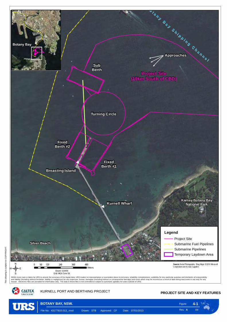
Project Site(10km South of CBD)
Kamay Botany BayNational ParkKurnell Wharf
Silver Beach
BB oo tt aa nn yy BB aa yy SS hh ii pp pp ii nn gg CC hh aa nn nn ee ll
Breasting Island
Approaches
FixedBerth #2
FixedBerth #1
SubBerth
Turning Circle
Figure:
Rev. A4
4-1
KURNELL PORT AND BERTHING PROJECT PROJECT SITE AND KEY FEATURES
This
drawin
g is s
ubjec
t to C
OPYR
IGHT
.
/
A
0 120 240 360 48060Meters
Datum: GDA94Grid: MGA Zone 56
File No: 43177815.013_.mxd Drawn: STB Approved: CF Date: 07/01/2013
Whilst every care is taken by URS to ensure the accuracy of the digital data, URS makes no representation or warranties about its accuracy, reliability, completeness, suitability for any particular purpose and disclaims all responsibilityand liability (including without limitation, liabili ty in negligence) for any expenses, losses, damages (including indirect or consequential damage) and costs which may be incurred as a result of data being inaccurate in any way for any reason. Electronic files are provided for information only. The data in these files is not controlled or subject to automatic updates for users outside of URS.
Source: Aerial Photography - Bing Maps © 2010 Microsoft Corporation and its data suppliers
BOTANY BAY, NSW.
LegendProject Site
Submarine Fuel Pipelines
Submarine Pipelines
Temporary Laydown Area
Botany Bay

Breasting Island
Figure:
Rev. A4
4-2
DREDGE FOOTPRINT
This
drawi
ng is
subje
ct to
COPY
RIGH
T.
AFile No: 43177815.067.mxd Drawn: STB Approved: SM Date: 08/01/2013
Whilst every care is taken by URS to ensure the accuracy of the digital data, URS makes no representation or warranties about its accuracy, reliability, completeness, suitability for any particular purpose and disclaims all responsibility and liability (including without limitation, liability in negligence) for any expenses,losses, damages (including indirect or consequential damage) and costs which may be incurred as a result of data being inaccurate in any way for any reason. Electronic files are provided for information only. The data in these files is not controlled or subject to automatic updates for users outside of URS.
KURNELL PORT AND BERTHING PROJECT
Source: Image supplied by Worley Parsons: 301015-03067-MA-DWG-148012-C.pdf
BOTANY BAY, NSW.

E n v i r o n m e n t a l I m p a c t S t a t e m e n t C h a p t e r 4 P r o p o s e d W o r k s D e s c r i p t i o n
Kurnell Port and Berthing Facility Upgrade 4-5
The anticipated dredge program would remain flexible to the shipping and berthing schedule. Sheet piling would take place first at fixed berth #1. Following sheet piling, dredging would commence, and afterwards, the rock forming the revetment would be placed at the southern end of the berth. The precise order of activities would be dictated by the shipping schedule and any associated access.
In total, approximately 153,000 m3 of material would be dredged to achieve the desired navigation depth across the footprint. The preference would be to dispose of the majority of these materials offshore (see Section 4.4.9), with the exception of up to approximately 6,000 m3, which would be reused locally (see Section 4.4.9).
The result of the dredging would be to return the turning circle and approaches to the design depth of 12.8 m below CD, whilst the sub berth would be returned to the design depth of 14 m below CD. The fixed berths would be dredged to increase the size of the berth boxes and their overall effective depth (12.8 m below CD).
Table 4-1 provides a summary of the proposed dredging works, showing the area, depth and volume of the proposed works. The table includes the required dredge volumes inclusive of an over dredging allowance to account for a degree of inhere inaccuracy from achieving the final dredge profile (common to any dredging works) and issues of future settlement. This accepted allowance is referred to as over dredging.
Table 4-1 Proposed Dredging Area, Depth and Volume
Location
Required Dredge Depth
to CD* (excluding
over dredging)
Design Area (m2)
Required Dredge
Volume (m3)
Additional Dredge
Volume to allow for over dredging (m3)
Total Volume
(including over dredging (m3)
Approaches & Turning Circle
-12.8 98,750 30,500 29,750 60,250
Sub Berth -14 16,750 7,750 5,000 12,750
Fixed Berths -12.8 62,500 61,250 18,750 80,000
Total - 178,000 99,500 53,500 153,000
*Note: Depth to seabed and not ships keel.
4.4.2 Proposed Dredging Method The proposed dredging works would be undertaken using a mechanical dredging technique. This would involve using a backhoe dredger (BHD) to load the dredged sediments onto split hopper barges. The BHD method is comparable to a normal land based excavator where the materials would be dredged from the seabed through mechanical digging. Following loading, the materials would be transported to the disposal/reuse areas where they would be unloaded from the bottom of the split hopper barge.
This method of dredging has the benefit of allowing controlled and more accurate dredging to take place around structures and is therefore appropriate for dredging next to the Kurnell Wharf, whilst allowing dredging to take place across the rest of the footprint. It is also environmentally favourable compared to other dredging options (see Chapter 2, Needs and Alternatives) as it causes less initial disturbance to the seabed therefore limiting sediment dispersion and the associated impacts (see Chapter 8, Hydrodynamics and Coastal Process and Chapter 10, Water and Sediment Quality).

C h a p t e r 4 P r o p o s e d W o r k s D e s c r i p t i o n E n v i r o n m e n t a l I m p a c t S t a t e m e n t
4-6 Kurnell Port and Berthing Facility Upgrade
Figure 4-3 provides an example illustration of a BHD. The size of the BHD required depends on the extent of the dredge area. BHDs include ‘spuds’ (anchoring legs) to create a suspended platform on the seabed. The dredgers rely on the use of diesel generators, compressors and pumps to undertake the works.
Based on the preliminary engineering design, Caltex would require a BHD with the following indicative specifications.
Table 4-2 Backhoe Dredger Indicative Design Specifications
Dimensions Units
Overall Length 50 m
Breadth 15 m
Moulded Depth 3 m
Dredging Draught 2 m
Tonnage 646 GT
Maximum Dredging Depth 19.5 m
Grab Capacity up to 6 m3
Total Power Installed 1,380 kW
Typical Noise Generated at Source *100-110 dB(A)
*The noise generated by each dredger depends on the type and age of dredger. Newer dredgers are typically fitted with better acoustic insulation.
Figure 4-4 provides an example illustration of a split hopper barge. A tugboat would be used to position and manoeuvre the split hopper.
As the hopper barge is separate to the dredger it allows continuous dredging because a replacement hopper can moor alongside the dredger as the full hopper is transported to the disposal/reuse areas.
Whilst split hoppers vary in size, barges with a capacity to hold 500 m3 have been identified as suitable for these proposed works. Barges of this size have sufficient manoeuvrability and draft to access the shallow waters close to the fixed berths.
To minimise the duration of the works, it is anticipated that four hopper barges (and supporting tugboats) would be used on a rotational basis. One would be in the process of being loaded, with one moored alongside the BHD. The remaining two would be either in transit to, or from, the disposal ground.
4.4.3 Overall Timing and Shipping Movements
It is anticipated that on average, approximately:
2,000 m3 of material would be dredged from the approaches, turning circle and sub berth per day; and
850-1,000 m3 of material would be dredged from the fixed berths per day.
At these rates, it would take approximately 23 weeks to complete the proposed dredging works (see Table 4-4).
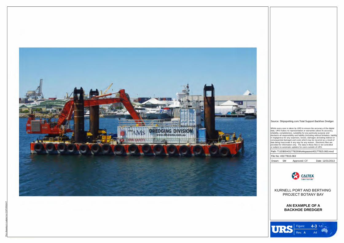
Figure:
Rev. A4
4-3
KURNELL PORT AND BERTHING PROJECT BOTANY BAY
This
drawin
g is s
ubjec
t to C
OPYR
IGHT
.
A
Whilst every care is taken by URS to ensure the accuracy of the digital data, URS makes no representation or warranties about its accuracy, reliability, completeness, suitability for any particular purpose and disclaims all responsibility and liability (including without limitation, liability in negligence) for any expenses, losses, damages (including indirect or consequential damage) and costs which may be incurred as a result of data being inaccurate in any way for any reason. Electronic files are provided for information only. The data in these files is not controlled or subject to automatic updates for users outside of URS.
Path: T:\JOBS\43177815\Workspaces\43177815.063.mxd
File No: 43177815.063
Drawn: SM Approved: CF Date: 11/01/2013
AN EXAMPLE OF ABACKHOE DREDGER
Source: Shipspotting.com.Total Support Backhoe Dredger.
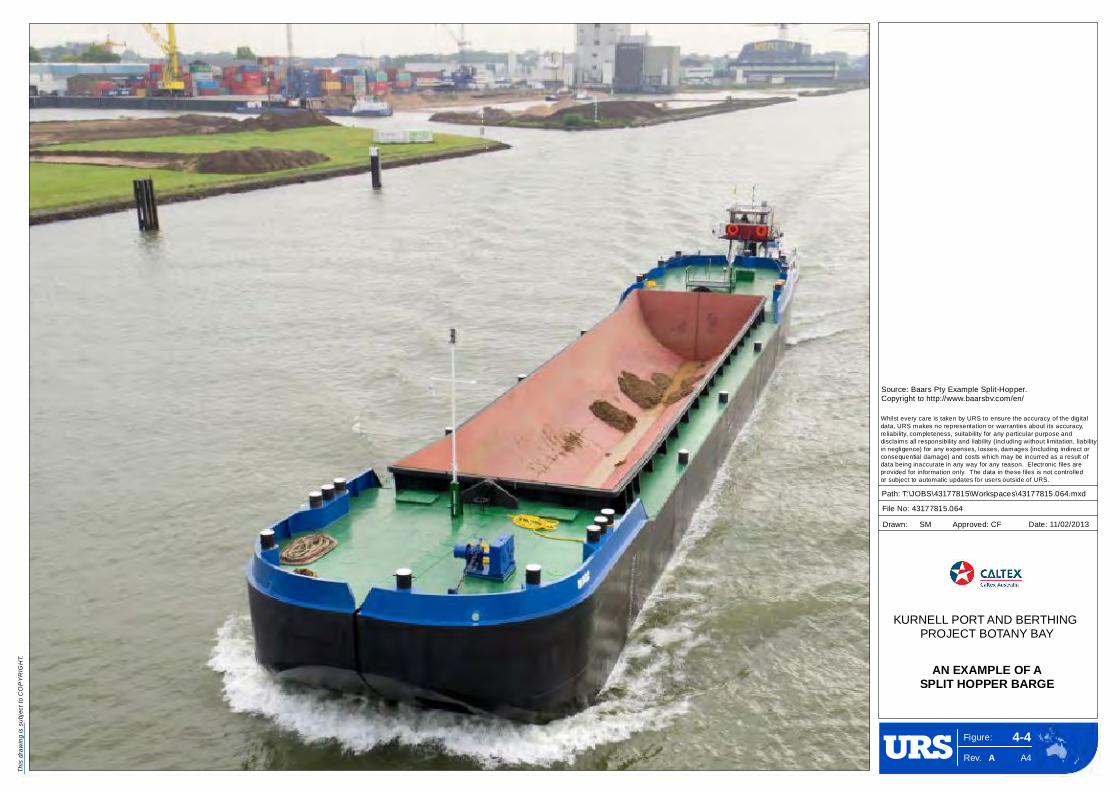
Figure:
Rev. A4
4-4
KURNELL PORT AND BERTHING PROJECT BOTANY BAY
This
drawi
ng is
subje
ct to
COPY
RIGH
T.
A
Whilst every care is taken by URS to ensure the accuracy of the digital data, URS makes no representation or warranties about its accuracy, reliability, completeness, suitability for any particular purpose and disclaims all responsibility and liability (including without limitation, liability in negligence) for any expenses, losses, damages (including indirect or consequential damage) and costs which may be incurred as a result of data being inaccurate in any way for any reason. Electronic files are provided for information only. The data in these files is not controlled or subject to automatic updates for users outside of URS.
Path: T:\JOBS\43177815\Workspaces\43177815.064.mxd
File No: 43177815.064
Drawn: SM Approved: CF Date: 11/02/2013
AN EXAMPLE OF ASPLIT HOPPER BARGE
Source: Baars Pty Example Split-Hopper.Copyright to http://www.baarsbv.com/en/

E n v i r o n m e n t a l I m p a c t S t a t e m e n t C h a p t e r 4 P r o p o s e d W o r k s D e s c r i p t i o n
Kurnell Port and Berthing Facility Upgrade 4-9
4.4.4 Dredging Schedule
The rotational management of split hopper barges would allow the BHD to continually dredge. There would be short breaks in the dredging program to allow for crews to be switched over (assuming there to be two rotational crews, each working 12-hour shifts) and for the BHD to be repositioned and resupplied.
This would equate to approximately a 2-hour break in dredging on any given day.
It is also anticipated that the dredging would take place continuously with the requirement for short breaks for refuelling, maintenance, servicing, taking on supplies and to accommodate the continued berthing at the facility as discussed below.
Whilst the objective of the approximate 23 week schedule would be to continually dredge, the works
would need to remain flexible to allow continued operation of the port and berthing facility. This may result in short periods when the works would stop or the dredger shifts its operations to another unaffected part of the footprint. It would be unlikely that continuous dredging would be achieved across any specific area
of the footprint prior to achieving the required depth and profile.
These breaks in the program have been accounted for in the hydrodynamic modelling in Technical Appendix C.
4.4.5 Ship Movements
It is estimated that the proposed works would require the equivalent of approximately 374 split hopper loads to remove the total volume of dredged sediments. This assumes loads taken from the fixed berths contain 30% excess water. Approximately 12 hopper loads would be required to transfer clean materials
to the reuse areas (see Section 4.4.9) with the remaining loads transferred to the Sydney Offshore Spoil Ground (see Section 4.4.9).
4.4.6 Dewatering
The BHD would remove dredged sediment from the seabed in a closed bucket, lifting it through the water column before slewing (transferring) it over and releasing it into an adjacent split hopper barge.
The dredged sediment would include a volume of surplus water. The volume of surplus water depends on
the composition of what is being dredged and can be considerable, especially in areas of softer sandier sediment as are present within the majority of the dredge footprint.
In order to reduce the duration of works it is common practice to allow the majority of the excess water to overflow from the side of the split hopper barge prior to the materials being transported elsewhere. This
process is known as overflow dredging and would take place in the approaches, sub berth and the turning circle. Overflow dredging would not be permitted within the fixed berths and in front of the submarine berth due to the presence of contaminated sediments. The rate of overflow dredging depends on the size
and type of hopper barge used. Under the working assumption of using 500 m3 capacity hoppers, it is anticipated that approximately 15-20 m3 of water would overflow every minute. The overflow would also contain a quantity of finer sediment, which would not instantly settle out in the hopper. The corresponding
‘spill rate’ of this sediment is anticipated to be approximately 10-15 kg per second.
Validation sampling, monitoring and various environmental controls are proposed to manage the BHD works. These measures are discussed in Chapter 10, Water and Sediment Quality.
C h a p t e r 4 P r o p o s e d W o r k s D e s c r i p t i o n E n v i r o n m e n t a l I m p a c t S t a t e m e n t
4-10 Kurnell Port and Berthing Facility Upgrade
4.4.7 Anchoring & Mooring
The BHD would be fixed in place using its spuds (anchoring legs), removing the need for anchor lines. The split hopper barges and tugboats would moor against the BHD when in use. When not in use they would moor east of the breasting island near fixed berth #1.
Whilst working in the fixed berths it may be possible to moor the BHD against the breasting island. This
would depend on the final choice of BHD. The alternative would be for the BHD to deploy its spuds consistent with the conventional approach to mooring for the rest of the dredge footprint.
4.4.8 Materials and Waste
The works would generate small quantities of waste diesels, oils and lubricants, hydraulic fluid, sewage, cooking oil, ablutions and detergents. These wastes would be stored and collected for onshore disposal
at an appropriate licenced facility (see Chapter 16, Waste and Resource Management). Each ship would carry an approved spill kit and containment provisions (i.e. bunded areas), working under practices consistent with Caltex’s procedures for managing waste (see Section 16.5) so as to ensure appropriate
storage, transfer, handling, management and disposal.
There would be no requirement to stockpile spoil or waste materials (on land) during the works. However, there would be some limited materials set down within the existing storage area along Prince Charles Parade (see Figure 4-15 and Section 4.5.1).
4.4.9 Reuse and Disposal
Reuse
Approximately 6,000 m3 of clean dredged sediment taken, either from the area north of the sub berth or the area on the southeast side of the turning circle, would be reused (see Figure 4-5).
The majority of reclaimed sediments (up to approximately 4,500 m3) would be used to fill in a former anchoring hole located within centre of the turning circle (3348.90E, 62367.95N), with the remaining
1,500 m3 used to cover two exposed sections of the submarine fuel supply pipelines located behind the sub-berth (northern end: 334425.91E, 6237067.74N; southern end: 334400.38N, 6237067.74E).
The reuse locations are shown on Figure 4-6. Small quantities of sediment (less than 100 m3) may also be used in other spot locations. This would depend on future requirements and availability.
The submarine fuel pipelines have become exposed over the past three years as is evident from regular
hydrographic surveying of the area. This has resulted in damage to their outer casing most likely due to recreational ships dropping anchor over the pipelines. Therefore the proposal would cover the two 100 m long exposed sections of the pipelines to a width of 7 m and a depth of approximately 0.7 m on average.
The clean dredged sediments would be placed over the submarine fuel pipelines and anchor point by
positioning split hopper barges over the relevant locations shown on Figure 4-6 and releasing the materials from the bottom of the hopper.
This element of the proposed works would take one week to complete and would be undertaken in parallel with the dredging works.

Kamay Botany BayNational Park
Silver Beach
BBoo
tt aann
yy BB
aayy
SShh
ii pppp
ii nngg
CChh
aann
nnee
ll
Figure:
Rev. A4
4-5
KURNELL PORT AND BERTHING PROJECT AREAS OF RESUABLE DREDGED SEDIMENT
This
dra
win
g is s
ubje
ct to
CO
PY
RIG
HT.
/
A
0 150 300 450 60075
Meters
Datum: GDA94Grid: MGA Zone 56
File No: 43177815.024.mxd Drawn: SB Approved: CF Date: 13/12/2012
Whilst every care is taken by URS to ensure the accuracy of the digital data, URS makes no representation or warranties about its accuracy, reliability, completeness, suitability for any particular purpose and disclaims all responsibilityand liability (including without limitation, liability in negligence) for any expenses, losses, damages (including indirect or consequential damage) and costs which may be incurred as a result of data being inaccurate in any way for any reason. Electronic files are provided for information only. The data in these files is not controlled or subject to automatic updates for users outside of URS.
Source: Aerial Photography - Bing Maps © 2010 Microsoft Corporation and its data suppliers
BOTANY BAY, NSW.
Legend
Project Site
Dredge Footprint
Submarine Fuel Pipelines
Sediment Reuse Area
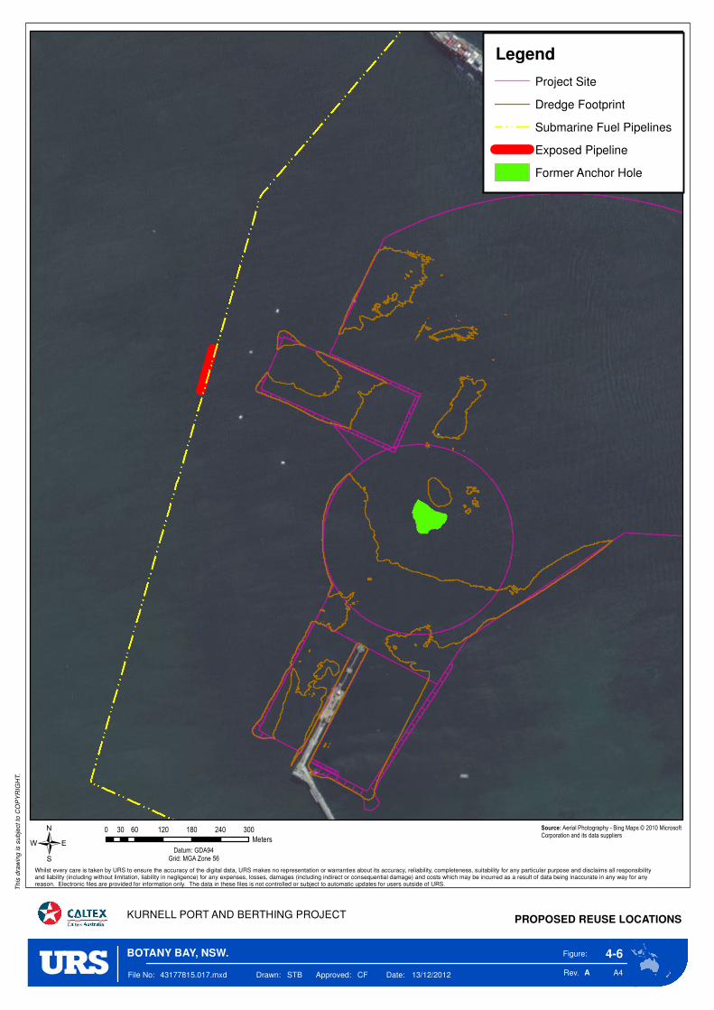
Figure:
Rev. A4
4-6
KURNELL PORT AND BERTHING PROJECT PROPOSED REUSE LOCATIONS
This
dra
win
g is s
ubje
ct to
CO
PY
RIG
HT.
/
A
0 60 120 180 240 30030
Meters
Datum: GDA94Grid: MGA Zone 56
File No: 43177815.017.mxd Drawn: STB Approved: CF Date: 13/12/2012
Whilst every care is taken by URS to ensure the accuracy of the digital data, URS makes no representation or warranties about its accuracy, reliability, completeness, suitability for any particular purpose and disclaims all responsibilityand liability (including without limitation, liability in negligence) for any expenses, losses, damages (including indirect or consequential damage) and costs which may be incurred as a result of data being inaccurate in any way for any reason. Electronic files are provided for information only. The data in these files is not controlled or subject to automatic updates for users outside of URS.
Source: Aerial Photography - Bing Maps © 2010 Microsoft Corporation and its data suppliers
BOTANY BAY, NSW.
Legend
Project Site
Dredge Footprint
Submarine Fuel Pipelines
Exposed Pipeline
Former Anchor Hole

E n v i r o n m e n t a l I m p a c t S t a t e m e n t C h a p t e r 4 P r o p o s e d W o r k s D e s c r i p t i o n
Kurnell Port and Berthing Facility Upgrade 4-13
Disposal
The remaining dredged sediment identified as not suitable for reuse (approximately 147,000 m3) would be disposed of at the Sydney Offshore Spoil Ground (see Figure 4-7). The disposal ground is located approximately 25 km from the dredge footprint, 10 km east-southeast off Sydney Heads in water depths approximately 100 to 130 m below CD. The offshore disposal grounds cover an area of approximately 23 km2.
The disposal of the materials would be subject to permit approval from the Commonwealth Government under the terms of the Environment Protection (Sea Dumping) Act 1981.
For the materials to be acceptable for sea dumping they must be subjected to a process of analysis and testing. The Department of Sustainability, Environment, Water, Population and Communities (SEWPAC) oversees this process. It requires a Sampling and Analysis Plan (SAP) to be prepared setting out the testing regime. Once accepted, the SAP is implemented with the test data being reported in support of the application for a Sea Dumping Permit (SDP).
A SAP implementation plan has been completed for the proposed works (see Technical Appendices D1 and D2). This confirms that the dredged sediments would be suitable for disposal at the Sydney Offshore Spoil Ground despite elevated concentrations of tributyltin (TBT)4. It also confirms the suitability for up to 7,800 m3 of dredge material to be reused within Botany Bay due to it being uncontaminated.
4.5 Wharf and Berth Upgrade
4.5.1 Fixed Berth Upgrade
Berth Boxes
The existing fixed berths were constructed in the 1950s at the same time as the main wharf structure. Fixed berth #2 was subsequently upgraded in 2002.
Table 4-3 shows the current dimensions of the fixed berths and their revised size following the proposed dredging works. The table also shows the maximum capacity of ship that could be accommodated within the revised berth boxes.
Table 4-3 Change in Effective Dimensions of the Fixed Berths
Berth Final Depth
(meters below CD)
Length (m) Width (m) Ship Size
Length Overall (LOA)
Ship Deadweight
tonnes (DWT) Fixed berth #1
Existing Various 233 35 180 50,000
Proposed -12.8 310 135-165 250 100,000
Fixed berth #2
Existing Various 250 35 180 50,000
Proposed -12.8 245 100 200 50,000
4 Section 1.3 Caltex Dredging: Sediment Sampling and Analysis Plan Implementation Report, Worley Parsons (2012).
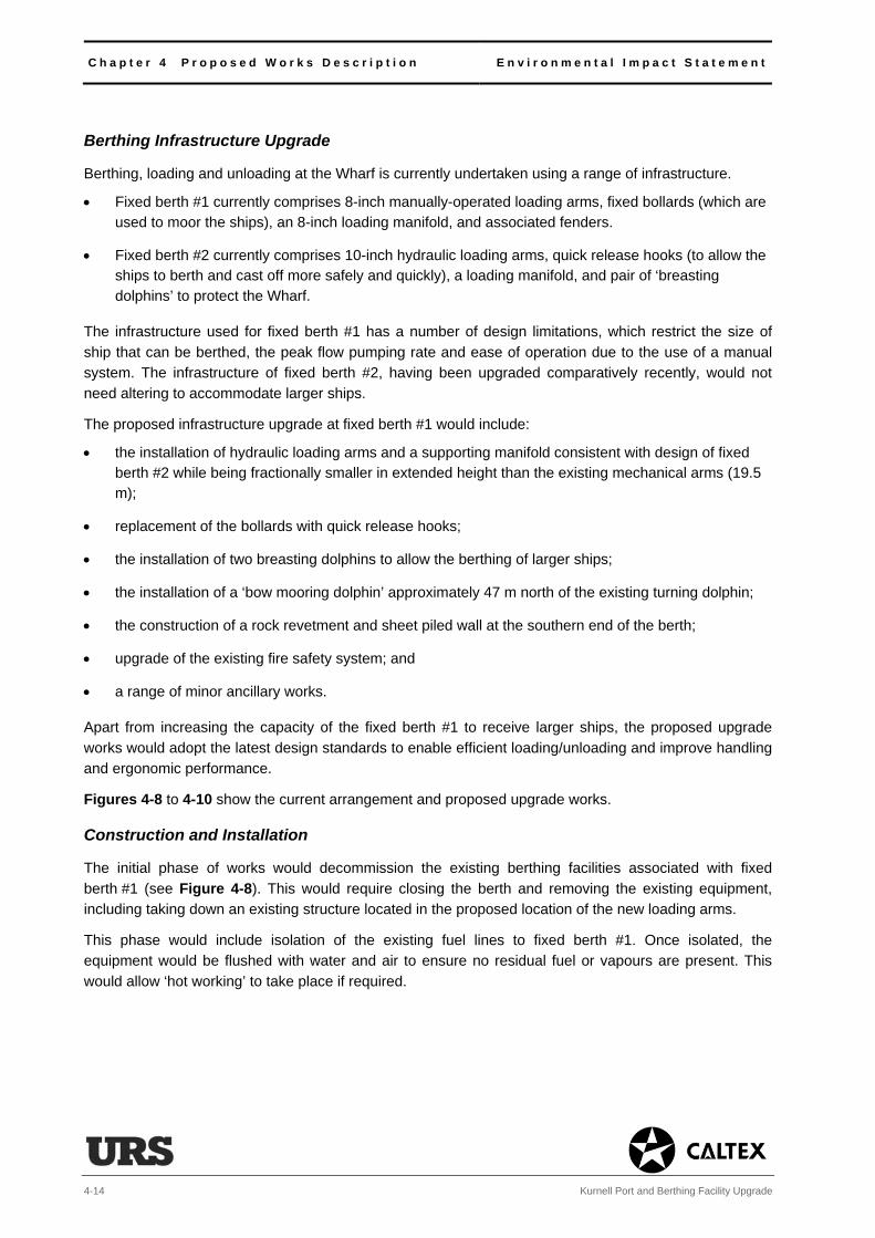
C h a p t e r 4 P r o p o s e d W o r k s D e s c r i p t i o n E n v i r o n m e n t a l I m p a c t S t a t e m e n t
4-14 Kurnell Port and Berthing Facility Upgrade
Berthing Infrastructure Upgrade
Berthing, loading and unloading at the Wharf is currently undertaken using a range of infrastructure.
Fixed berth #1 currently comprises 8-inch manually-operated loading arms, fixed bollards (which are used to moor the ships), an 8-inch loading manifold, and associated fenders.
Fixed berth #2 currently comprises 10-inch hydraulic loading arms, quick release hooks (to allow the ships to berth and cast off more safely and quickly), a loading manifold, and pair of ‘breasting dolphins’ to protect the Wharf.
The infrastructure used for fixed berth #1 has a number of design limitations, which restrict the size of
ship that can be berthed, the peak flow pumping rate and ease of operation due to the use of a manual system. The infrastructure of fixed berth #2, having been upgraded comparatively recently, would not need altering to accommodate larger ships.
The proposed infrastructure upgrade at fixed berth #1 would include:
the installation of hydraulic loading arms and a supporting manifold consistent with design of fixed berth #2 while being fractionally smaller in extended height than the existing mechanical arms (19.5 m);
replacement of the bollards with quick release hooks;
the installation of two breasting dolphins to allow the berthing of larger ships;
the installation of a ‘bow mooring dolphin’ approximately 47 m north of the existing turning dolphin;
the construction of a rock revetment and sheet piled wall at the southern end of the berth;
upgrade of the existing fire safety system; and
a range of minor ancillary works.
Apart from increasing the capacity of the fixed berth #1 to receive larger ships, the proposed upgrade
works would adopt the latest design standards to enable efficient loading/unloading and improve handling and ergonomic performance.
Figures 4-8 to 4-10 show the current arrangement and proposed upgrade works.
Construction and Installation
The initial phase of works would decommission the existing berthing facilities associated with fixed
berth #1 (see Figure 4-8). This would require closing the berth and removing the existing equipment, including taking down an existing structure located in the proposed location of the new loading arms.
This phase would include isolation of the existing fuel lines to fixed berth #1. Once isolated, the equipment would be flushed with water and air to ensure no residual fuel or vapours are present. This
would allow ‘hot working’ to take place if required.

Figure:
Rev. A4
4-7
KURNELL PORT AND BERTHING PROJECT BOTANY BAY
Th
is d
raw
ing
is s
ub
ject
to C
OP
YR
IGH
T.
A
Footnote 5: Taken from Caltex Dredging: Sediment Sampling andAnalysis Plan Implementation Report, Worley Parsons (2012)
Whilst every care is taken by URS to ensure the accuracy of the digital data, URS makes no representation or warranties about its accuracy, reliability, completeness, suitability for any particular purpose and disclaims all responsibility and liability (including without limitation, liability in negligence) for any expenses, losses, damages (including indirect or consequential damage) and costs which may be incurred as a result of data being inaccurate in any way for any reason. Electronic files are provided for information only. The data in these files is not controlled or subject to automatic updates for users outside of URS.
Path: T:\JOBS\43177815\Workspaces\43177815.012_.mxd
File No: 43177815.012_
Drawn: STB Approved: CF Date: 12/10/2012
SYDNEY OFFSHORE DISPOSAL GROUND

35 m35 m
Figure:
Rev. A4
4-8
KURNELL PORT AND BERTHING PROJECTCURRENT BERTHING ARRANGEMENT
AROUND THE FIXED BERTHS
This
drawin
g is s
ubjec
t to C
OPYR
IGHT
.
/
A
0 50 100 150 20025Meters
Datum: GDA94Grid: MGA Zone 56
File No: 43177815.021.mxd Drawn: STB Approved: SM Date: 13/12/2012
Whilst every care is taken by URS to ensure the accuracy of the digital data, URS makes no representation or warranties about its accuracy, reliability, completeness, suitability for any particular purpose and disclaims all responsibilityand liability (including without limitation, liabi lity in negligence) for any expenses, losses, damages (including indirect or consequential damage) and costs which may be incurred as a result of data being inaccurate in any way for any reason. Electronic files are provided for information only. The data in these files is not controlled or subject to automatic updates for users outside of URS.
Source: Aerial Photography - Bing Maps © 2010 Microsoft Corporation and its data suppliers
BOTANY BAY, NSW.
LegendExisting Berth Boxes
Medium Range Ship
Submarine Fuel Pipelines
250 m
233 m
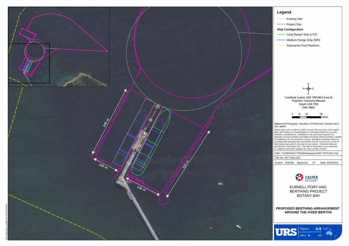
Figure:
Rev. A4
4-9
This
drawi
ng is
subje
ct to
COPY
RIGH
T.
/
A
0 50 10025Meters
Whilst every care is taken by URS to ensure the accuracy of the digital data, URS makes no representation or warranties about its accuracy, reliability, completeness, suitability for any particular purpose and disclaims all responsibility and liability (including without limitation, liability in negligence) for any expenses, losses, damages (including indirect or consequential damage) and costs which may be incurred as a result of data being inaccurate in any way for any reason. Electronic files are provided for information only. The data in these files is not controlled or subject to automatic updates for users outside of URS.
245 m
310 m100 m
135 m
Path: T:\JOBS\43177815\Workspaces\43177815.022.mxd
File No: 43177815.022
Drawn: STB/SB Approved: CF Date: 8/01/2013
Coordinate System: GDA 1994 MGA Zone 56Projection: Transverse Mercator
Datum: GDA 1994Units: Meter
PROPOSED BERTHING ARRANGEMENT AROUND THE FIXED BERTHS
LegendExisting Site
Project Site
Ship ConfigurationLong Range Ship (LR2)
Medium Range Ship (MR)
Submarine Fuel Pipelines
KURNELL PORT AND BERTHING PROJECT
BOTANY BAY
Source: Aerial Photography - Bing Maps © 2010 Microsoft Corporation and its data suppliers

C h a p t e r 4 P r o p o s e d W o r k s D e s c r i p t i o n E n v i r o n m e n t a l I m p a c t S t a t e m e n t
4-18 Kurnell Port and Berthing Facility Upgrade
The water flushed through the equipment would be directed to specific ‘slop drums’. The oily water would
then be pumped to the dedicated ‘slop line’ using the existing ‘slop pumps’ installed on the Wharf. The oily water would be treated in the Refinery at its dedicated waste water treatment plant (WWTP) prior to disposal under the terms of the Refinery’s environmental protection licence (EPL). It is estimated that the
flushing waters would total approximately 10,000 m3.
Once the supply lines are deemed gas-free they would either be cold-cut or hot-worked into 6 m sections. The pipe ends would be sealed with plastic, taped and loaded on to semi-trailers and transported on to the main refinery site where they would be hydro-blasted in a dedicated area to remove any residual oil.
Again, any oily water generated would be treated in the WWTP prior to its controlled disposal under licence.
The loading arms and manifold equipment would be dismantled and cleaned in the same fashion as the supply lines.
The redundant pipe and loading arms would be held in the metal yard at the Refinery prior to being
recycled offsite.
Manifold Installation
To allow the installation of the new loading arms, a new manifold would be installed in the middle of the breasting island adjacent to the existing fixed berth #2 manifold (see Figure 4-10).
The new manifold would be installed onto an existing 50 m2 steel structure anchored into the concrete
deck of the breasting island. The new manifold would be connected to the existing supply lines that currently run from the Wharf to the Refinery.
Loading Arms & Quick Release Hooks
The replacement and relocation of the loading arms (approximately 16 m north of the current loading arms (see Figures 4-10 and 4-11)) would be undertaken from the wharf deck. Three loading arms would be mounted onto a prefabricated steel structure that would be anchored to the existing wharf top-deck.
Three short piping spools would be installed at the wharf lower deck to connect the loading arms to the new manifold.
Quick-release hooks would be installed at various locations to replace the existing bollards. The hooks would be anchored to the Wharf top-deck concrete structure.
Electrical cabling would be installed to supply a small hydraulic station for the loading arms, quick release
hooks and valves. The cabling would be ducted, running from the existing motor control centre located on the Wharf.

Figure:
Rev. A4
4-10
PROPOSED INFRASTRUCTUREUPGRADE AT FIXED BERTH #1
This
drawi
ng is
subje
ct to
COPY
RIGH
T.
AFile No: 43177815.027b.mxd Drawn: STB/SB Approved: SM Date: 20/12/2012
Whilst every care is taken by URS to ensure the accuracy of the digital data, URS makes no representation or warranties about its accuracy, reliability, completeness, suitability for any particular purpose and disclaims all responsibility and liability (including without limitation, liability in negligence) for any expenses,losses, damages (including indirect or consequential damage) and costs which may be incurred as a result of data being inaccurate in any way for any reason. Electronic files are provided for information only. The data in these files is not controlled or subject to automatic updates for users outside of URS.
KURNELL PORT AND BERTHING PROJECT
Source: 2D Image supplied by Worley Parsons - Drawing number 148229 'Jetty Upgrade General Plan Arrangement' [12/11/2012]
BOTANY BAY, NSW.
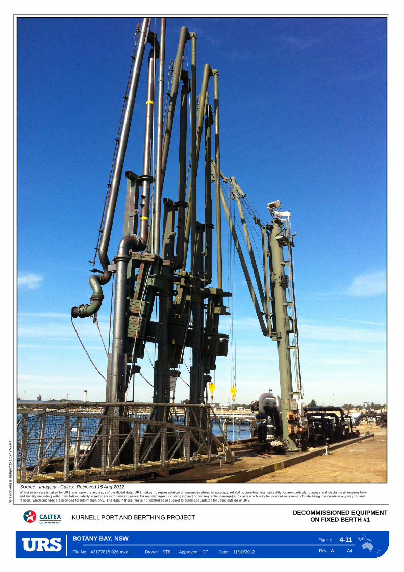
Figure:
Rev. A4
4-11
KURNELL PORT AND BERTHING PROJECTDECOMMISSIONED EQUIPMENT
ON FIXED BERTH #1
This
drawi
ng is
subje
ct to
COPY
RIGH
T.
AFile No: 43177815.026.mxd Drawn: STB Approved: CF Date: 11/10/2012
Whilst every care is taken by URS to ensure the accuracy of the digital data, URS makes no representation or warranties about its accuracy, reliability, completeness, suitabili ty for any particular purpose and disclaims all responsibili tyand l iability (including without limitation, liabi lity in negligence) for any expenses, losses, damages (including indirect or consequential damage) and costs which may be incurred as a result of data being inaccurate in any way for any reason. Electronic files are provided for information only. The data in these files is not controlled or subject to automatic updates for users outside of URS.
BOTANY BAY, NSW
Source: Imagery - Caltex. Recieved 15 Aug 2012.

E n v i r o n m e n t a l I m p a c t S t a t e m e n t C h a p t e r 4 P r o p o s e d W o r k s D e s c r i p t i o n
Kurnell Port and Berthing Facility Upgrade 4-21
Breasting and Bow Mooring Dolphins – Fixed Berth #1
A single mooring dolphin and two berthing dolphins (forming a breasting dolphin) would be installed (see
Figure 4-10). Each would comprise an approximate 10 m by 10 m structure suspended on a concrete cap, which in turn would sit on tubular steel piles. The structures would be at the same level as the existing berth dolphins (approximately 35 m CD). A remotely operated quick release hook would be
installed on each dolphin along with a hand railing, rope railing, lighting, power supply, access ladder and life jackets.
Each dolphin (see Figure 4-10) would require its tubular steel piles to be founded 25-30 m into the bedrock. The preferred method of piling would be a pre-cast method, whereby each tubular steel pile
would be initially vibrated in to the upper layers before being driven in to the ground using a drop hammer. Once the first part of the pile is driven into the ground it is extended using mechanical interlocking joints, which means that the units can be rapidly coupled to extend the pile to the required
foundation depth with minimum interruptions whilst driving. Each tubular steel pile is reinforced throughout its length with high tensile steel.
The vibration and drop hammer would operate from a jack-up barge, with the tubular steel piles delivered to the project site by barge. In total 22 steel piles, 6 piles for each Breasting Dolphin and 8 for the Mooring
Dolphin, would be required, needing truck and barge deliveries during the course of the works.
Figure 4-12 shows a typical example of installing tubular steel piles. Further specific information on the piling is discussed in Section 4.5.1.
Following the completion of the piling works and trimming of piles to their approximate level, a temporary works platform would be installed by clamping it to the piles. The platform would allow workers to install
bracing to the pile group to then allow the precast breasting and bow mooring dolphin concrete tops to be installed. The design of the concrete top would comprise two precast concrete elements, one base plus four sides cast as one unit that would form a box (shell). Once the box is formed, it would be reinforced
and concrete would be poured into the shell to form the dolphin units.
For each of the dolphins, the prefabrication works required to create the formwork would be undertaken offsite. The units would be transported to site most likely by barge in the first instance, having been transferred at one of the locations discussed in Section 4.6.2.
Construction of the Rock Revetment and Sheet Piled Wall
Without additional engineering, the proposed increased size of fixed berth #1 would potentially undermine the integrity of the existing Wharf piles located at the back of the berth box. To prevent this, a rock revetment (see Figure 4-13) would be installed along with a sheet pile wall. The sheet pile wall would
extend approximately 70-80 m along the southern end of fixed berth #1 and form a height of approximately 6 m from the seabed (approximately 6.8 m below CD). In front of the sheet piled wall would be a rock revetment. This revetment would be approximately 10-15 m wide. It would comprise a
geotextile membrane over laid with graded, interlocked, quarried armour stone, followed by a less coarse under-layer with a finer gravel (filter) layer sitting next to the seabed. The angle of the revetment would be 1-in-2 (vertical to horizontal).
The sheet piled wall would be constructed using the same technique as for the other piling works. The
rock revetment would be created following the dredging of fixed berth #1. The gravel filter layer would be placed first, followed by the under layer and then the rock-armour layer. Staged construction along the length of the revetment would be anticipated to prevent erosion of the gravel filter layer (once placed).
C h a p t e r 4 P r o p o s e d W o r k s D e s c r i p t i o n E n v i r o n m e n t a l I m p a c t S t a t e m e n t
4-22 Kurnell Port and Berthing Facility Upgrade
Either the BHD, or a similar GPS-controlled excavator on a barge, would be used to construct the
revetment. It would upload graded stone onto the southern batter slope close to the seabed, allowing the revetment pile to build up gradually against the face.
It is anticipated that the rock would be sourced from Newcastle and transported directly to the project site on an ‘as-needs’ basis by ship.
It would take approximately 3 weeks of intermittent working to install the sheet piles. The rock revetment
works are expected to last approximately 4 weeks allowing for placement and settlement.

Figure:
Rev. A4
4-12
KURNELL PORT AND BERTHING PROJECTAN EXAMPLE OF A PILINGBARGE INSTALLING PILES
This
drawi
ng is
subje
ct to
COPY
RIGH
T.
AFile No: 43177815.061.mxd Drawn: STB Approved: CF Date: 11/10/2012
Whilst every care is taken by URS to ensure the accuracy of the digital data, URS makes no representation or warranties about its accuracy, reliability, completeness, suitabili ty for any particular purpose and disclaims all responsibili tyand l iability (including without limitation, liabi lity in negligence) for any expenses, losses, damages (including indirect or consequential damage) and costs which may be incurred as a result of data being inaccurate in any way for any reason. Electronic files are provided for information only. The data in these files is not controlled or subject to automatic updates for users outside of URS.
BOTANY BAY, NSW
Source: Imagery sourced from Waterway Constructions (Appendix A)

Figure:
Rev. A4
4-13
KURNELL PORT AND BERTHINGPROJECT, BOTANY BAY.
This
drawi
ng is
subje
ct to
COPY
RIGH
T.
A
Whilst every care is taken by URS to ensure the accuracy of the digital data, URS makes no representation or warranties about its accuracy, reliability, completeness, suitability for any particular purpose and disclaims all responsibility and liability (including without limitation, liability in negligence) for any expenses, losses, damages (including indirect or consequential damage) and costs which may be incurred as a result of data being inaccurate in any way for any reason. Electronic files are provided for information only. The data in these files is not controlled or subject to automatic updates for users outside of URS.
PATH: T:\JOBS\43177815\Workspaces\43177815.070.mxd
FILE NO: 43177815.070
DRAWN: STB APPROVED: CF DATE: 8/01/2013
ROCK REVETMENT INSTALLATION
Source:Worley Parsons - resources & energy. Drawing No. 148029, Rev C, Issued 20/12/12.

E n v i r o n m e n t a l I m p a c t S t a t e m e n t C h a p t e r 4 P r o p o s e d W o r k s D e s c r i p t i o n
Kurnell Port and Berthing Facility Upgrade 4-25
Fire Equipment Upgrade
The current wharf firewater system would be upgraded to cover the scenario of having both berths
occupied simultaneously. The upgrade would require the installation of a new monitor (see Figure 4-14) which would sit atop a 15 m high pipe stack attached to the Wharf with the capacity to reach and cover the entire tankage and deck of the larger ships. The monitor would connect directly in to the existing fire
water header.
Ancillary Structures
The following ancillary structures would be constructed.
New dolphins.
The upgrade (by replacement) of the existing fender and fender panels.
Piling
The main infrastructure upgrade works would comprise suspended structures supported on tubular steel piles. The piles would be handled, pitched and secured on to the seabed by a crane/rig mounted either
on a jack-up barge or floating barge restrained by mooring lines.
Initially the piles would be vibrated until ‘refusal’ or until the pile reaches depths of 1-2 m above the final embedment depth. The piling would then be completed by driving the piles with a drop hammer.
Geotechnical conditions may require further action for installing the piles. This may see the piling contractor drilling, chiselling or boring into the seabed to achieve the required embedment. It is also
possible that if adequate embedment cannot be achieved in the sandy seabed strata alone then some of the piles may need to be anchored to the bedrock. This requirement would only become apparent in the detailed design phase; however it has been accounted for in this EIS through the noise assessment (see
Chapter 13, Noise). Anchoring into rock would be achieved by drilling 4-10 m in to the bedrock and installing a steel anchored rod, then placing concrete to the base of the pile to achieve an anchor plug. If anchoring is required this would require a steady working platform such as a jack-up barge.
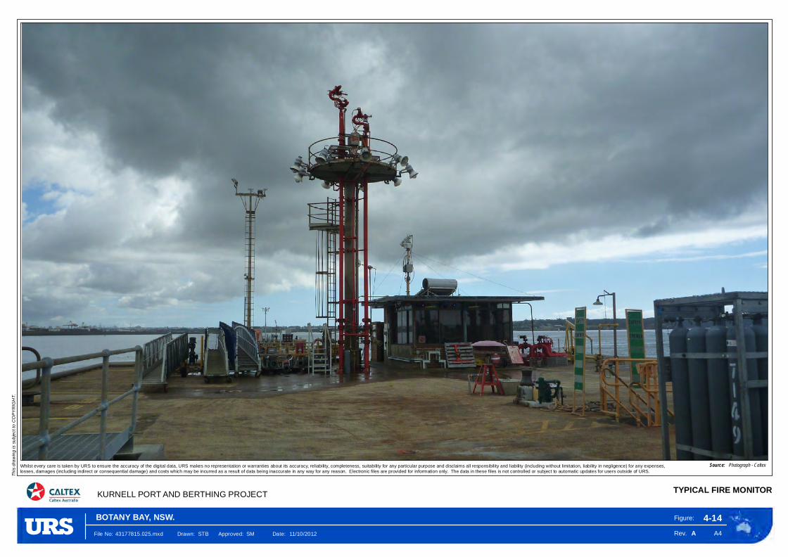
Figure:
Rev. A4
4-14
TYPICAL FIRE MONITOR
This
drawin
g is s
ubjec
t to C
OPYR
IGHT
.
AFile No: 43177815.025.mxd Drawn: STB Approved: SM Date: 11/10/2012
Whilst every care is taken by URS to ensure the accuracy of the digital data, URS makes no representation or warranties about its accuracy, reliability, completeness, suitability for any particular purpose and disclaims all responsibility and liability (including without limitation, liability in negligence) for any expenses,losses, damages (including indirect or consequential damage) and costs which may be incurred as a result of data being inaccurate in any way for any reason. Electronic files are provided for information only. The data in these files is not controlled or subject to automatic updates for users outside of URS.
KURNELL PORT AND BERTHING PROJECT
Source: Photograph - Caltex
BOTANY BAY, NSW.

E n v i r o n m e n t a l I m p a c t S t a t e m e n t C h a p t e r 4 P r o p o s e d W o r k s D e s c r i p t i o n
Kurnell Port and Berthing Facility Upgrade 4-27
Equipment, Construction, Laydowns and Site Offices
The proposed works to upgrade the fixed berth would require the use the following equipment:
barge mounted cranes;
work barges;
work boats;
dive boats;
fork lifts;
compressor;
mobile cranes;
jack-up barge and rock hammer;
vibratory pile;
diesel generators;
an air-operated bevelling machine;
welding and cutting equipment, including oxy acetylene cutting;
hand-held grinders;
X-Ray equipment; and
hydrostatic test pump for hydrotesting of pipe spools.
The installation of the fixed berth infrastructure would comprise the following.
The dolphin concrete superstructures would be placed in to position over the piles (either from the jetty deck or a floating barge).
The over-water concrete work would use precast elements including beams and slabs so that limited formwork6/falsework7 would be required. The precast elements would then be ‘stitched together’ using an in-situ concrete topping. This would be provided by trucks pumping the concrete from the breasting island.
The fenders would be installed from floating plant or mobile cranes on the working platform.
The quick release hooks and handrails would be installed once the dolphins were in place.
The access walkway would be fabricated offsite and transported in sections for assembly onsite. The walkway would be positioned by cranes and barge-mounted cranes.
6 This term is given to either temporary or permanent moulds into which concrete or similar materials are poured. 7 False work consists of temporary structures used in construction to support spanning or arched structures in order to hold the component in place until its construction is sufficiently advanced to support itself.
C h a p t e r 4 P r o p o s e d W o r k s D e s c r i p t i o n E n v i r o n m e n t a l I m p a c t S t a t e m e n t
4-28 Kurnell Port and Berthing Facility Upgrade
The works would require two temporary laydown areas to be created during construction.
The temporary laydown for the loading arms and quick release hooks would be within the Refinery site.
The temporary laydown for the proposed manifold pipe spools (connecting lengths of pipe) would be within the current storage areas contained in the right of way adjacent to Prince Charles Parade (see Figure 4-15). Additional materials that would be shipped immediately to site would be stored at the
dedicated existing storage site discussed in Section 4.6.2.
Temporary site offices would be located within the main Refinery site adjacent to the main workshop in the northwest corner.
4.5.2 Sub Berth Upgrade
The proposed changes to the sub berth are limited to an upgrade of its mooring system to comply with the latest industry standards and returning its depth to 14 m below CD. Whilst the works would not increase the berthing capacity, they would allow smaller ships to safely moor in the berth. As such, ships
ranging from 60,000 Deadweight Tonnage (DWT)8 to 200,000 DWT could use the sub berth following its upgrade. This would result in ships with length between 185 and 245 m using the sub berth.
Infrastructure Upgrade
The present moorings and buoys fall outside of the berthing box. They are either not optimally configured or have reached the end of their design life. The proposal focuses on the following reconfiguration (see Figure 4-16).
An upgrade of the mooring system to comply with the latest design safety guidelines9.
Replacement of the No.3 Buoy with a swamp mooring to allow safer mooring close to the submarine fuels pipelines that run behind the sub berth.
Replacement of the No.9 Buoy with a twin mooring buoy given that the existing buoy does not sit flat on the water, creating a navigation risk. The twin buoy would provide two separate lines for ship mooring.
The addition of a swamp mooring lines to be labelled No.6A, which would be located forward of the swamp mooring line of No.6 Buoy.
The replacement of the existing chains with higher quality and higher grade chains.
Replacement of the existing swamp mooring lines with high performance mooring lines.
The replacement of No.1, No.2, No.4 & No.5 twin mooring buoys with new twin mooring buoys fitted with twin remote operated quick release hooks.
8 A measure of how much weight a ship is carrying or can safely carry. 9 OCIMF Guidelines, 2010.

Figure:
Rev. A4
4-15
This
drawi
ng is
subje
ct to
COPY
RIGH
T.
/
A
0 200 400100Meters
Whilst every care is taken by URS to ensure the accuracy of the digital data, URS makes no representation or warranties about its accuracy, reliability, completeness, suitability for any particular purpose and disclaims all responsibility and liability (including without limitation, liability in negligence) for any expenses, losses, damages (including indirect or consequential damage) and costs which may be incurred as a result of data being inaccurate in any way for any reason. Electronic files are provided for information only. The data in these files is not controlled or subject to automatic updates for users outside of URS.
DredgeFootprint
Kamay Botany BayNational Park
FixedBerth #1
Kurnell Wharf
Silver Beach
KURNELL
TurningCircle
BB oo tt aa nn yy BB aa yy SS hh ii pp pp ii nn gg CC hh aa nn nn ee ll
Temporary Site Offices(Adjacent to the main workshop)
Temporary laydown for theproposed manifold pipe spools,
loading arms and quick release hooks.Acess To and From Wharf(Prince Charles Parade)
Acess to and from Kurnell Refinery(Solander Street)
Prefabricated Pipe Spools and Galvanised SteelStructure Platforms/Walkways to the Laydown Area in the
Right-of-way adjacent to Prince Charles Parade During Construction Phase.
The Stone for the Revetment would also be delivered to site by barge from Newcastle.
FixedBerth #2
Breasting Island
Kurnell Refinery
Torres St
Prince Charles Pde
Tasman St
Bridges St
Coo
k S
t
Polo St
Cap
tain
Coo
k D
r
Da
mpi
er
St
Bal
boa
St
Reserve Rd
Horning StS
ilver B
each R
d
Chi
solm
Rd
Sha
rn S
t
Captain Cook Dr Path: T:\JOBS\43177815\Workspaces\43177815.032_.mxd
File No: 43177815.032_
Drawn: STB Approved: CF Date: 8/01/2013
Coordinate System: GDA 1994 MGA Zone 56Projection: Transverse Mercator
Datum: GDA 1994Units: Meter
PRINCIPAL ACCESS ROUTES, LAYDOWNS AND LOADING AREAS
KURNELL PORT AND BERTHING PROJECT
LegendProject Site
Dredge Footprint
Submarine Fuel Pipelines
Streets
Temporary Laydown Area
!>
!>
!>
!>B o t a n y B a y
Port BotanyFishburn Road, Molineux Point
S y d n e yH a r b o u r
Port Kembla(approx 60 km)
White Bay/Sydney Ports Facility Glebe Island
Lewis Anchorage
!>
!>White Bay / SydneyPorts Facility
Glebe Island
Anzac Bridge
Source: Aerial Photography - Bing Maps © 2010 Microsoft Corporation and its data suppliers Streets - © Mapinfo Australia Pty Ltd and PSMA Australia Ltd
C h a p t e r 4 P r o p o s e d W o r k s D e s c r i p t i o n E n v i r o n m e n t a l I m p a c t S t a t e m e n t
4-30 Kurnell Port and Berthing Facility Upgrade
The introduction of quick-release hooks would reduce the need for mooring-line handling by up to 50%. The quick-release hooks would also be a safer method of mooring through removing the need to board the buoys to remove the mooring lines. They would also allow ships to de-berth in a much shorter time in the event of an emergency. The quick release hooks would be installed at all five mooring locations.
The removal of the preventer lines would also reduce mooring-line handling by up to 30%. The preventer
lines are large in diameter and currently present handling and manoeuvrability issues. A further issue is the slack tension on the lines, which is not suitable to allow the safe mooring of smaller ships in the sub berth. Replacement of the chains would be required to ensure compliance with the latest international
standards and regulations9.
Construction and Installation
The works would require the decommissioning of the existing mooring equipment and installation of prefabricated equipment delivered to the sub berth by barge from the possible locations identified in
Section 4.6.2.
Whilst the works could feasibly take place whilst the sub berth remained operational, this would increase the duration of construction. Consequently, a possible alternative of temporarily closing the berth whilst the works are undertaken is being considered (see Section 4.9.4).
In total it would take approximately 4-6 months to complete the upgrade of the sub berth.
Equipment and Materials Delivery
The proposed works to upgrade the sub berth would require the use the following equipment:
a barge that would include:
– a crane;
– a crib room;
– a workshop;
– a 400 cubic-foot per minute (cfm) compressor;
– a 20 kilovolt-ampere (kVa) generator;
– a hydraulically-operated anchoring system that would include chain rollers and winches;
– oxy-cutting and welding equipment;
– diving equipment including umbilicals, control panels and a 25-30 cfm compressor;
a tugboat, which would accompany the barge at all times; and
a crew boat.
When the equipment is not in use it would be moored. The tugboat would be moored to the east of the breasting island near fixed berth #1 and the barge would be moored in the one fixed berth that would not
be occupied at the time. The materials would be delivered via one of the locations listed in Section 4.6.2.

Figure:
Rev. A4
4-16
KURNELL PORT AND BERTHING PROJECT BOTANY BAY
This
drawi
ng is
subje
ct to
COPY
RIGH
T.
/
A
0 50 10025Meters
Whilst every care is taken by URS to ensure the accuracy of the digital data, URS makes no representation or warranties about its accuracy, reliability, completeness, suitability for any particular purpose and disclaims all responsibility and liability (including without limitation, liability in negligence) for any expenses, losses, damages (including indirect or consequential damage) and costs which may be incurred as a result of data being inaccurate in any way for any reason. Electronic files are provided for information only. The data in these files is not controlled or subject to automatic updates for users outside of URS.
Î
Î
Î
Î
ÎÎ
Î
Î
Î
Î
ÎÎ
Î
SubBerth #3
TurningCircle
Proposed TMB9 & QRH
ProposedSwamp Mooring
No. 3
TMB2 & Proposed QRH
TMB1 & Proposed QRH
TMB5 & Proposed QRH
TMB4 & Proposed QRH Existing
Swamp MooringNo. 6
ExistingSwamp Mooring
No. 8
ProposedSwamp Mooring
No. 6a
ProposedAnchor No. 6A
Stevpris Anchor
ExistingSwamp Mooring
No. 7
PATH: T:\JOBS\43177815\Workspaces\43177815.029.mxd
FILE NO: 43177815.029
DRAWN: STB APPROVED: CF DATE: 7/01/2013
Coordinate System: GDA 1994 MGA Zone 56Projection: Transverse Mercator
Datum: GDA 1994Units: Meter
PROPOSED SUB BERTHCONFIGURATION
LegendProject Site
Submarine Fuel Pipelines
Crude Oil Submarine Pipeline
Existing Stevpris AnchorsÎ 5 Tonne
Î 7 Tonne
Twin Buoys, Chains and Ship TypesBuoy
Proposed R3 Chains
Long Range Ship 1 (LR1)
Long Range Ship (LR2)
Medium Range Ship (MR)
Suezmax Ship
Notes:QRH - Quick Release HooksTMB - Twin Mooring Buoy

C h a p t e r 4 P r o p o s e d W o r k s D e s c r i p t i o n E n v i r o n m e n t a l I m p a c t S t a t e m e n t
4-32 Kurnell Port and Berthing Facility Upgrade
4.6 Traffic and Transportation
4.6.1 Construction Shipping The majority of the proposed works would be undertaken using the following ships.
During peak dredging there would be the use of a backhoe dredger, four spilt hopper barges and up to five tugboats. One or two additional service ships would be periodically required to facilitate crews
changing over, allow refuelling and/or provide supplies.
The dredger, two hoppers and supporting tugboats would be used to construct the rock revetment.
The dolphins and sub berth upgrade would require the use of a barge, supporting tugboat, crew ship and a dive team. The piles for the dolphins along with the prefabricated buoys, anchors and moorings for the berths would also be delivered to site via barge, road or potentially a mixture of
both. The stone for the revetment would also be delivered to site by barge from Newcastle.
The piles and metal work would be imported from overseas directly into Botany Bay. This would require 15-20 barge-loads over the duration of the works.
4.6.2 Construction Road Transport
Road Transport
A small amount of road traffic would be generated as a result of undertaking the proposed works.
Road transport would include equipment deliveries and personnel movements to and from the Wharf, Refinery and one or more of the following existing dedicated storage locations (in order of preference). The final storage location(s) would ultimately depend on the requirements of the works’ contractor and
their availability and capacity at the time.
Fishburn Rd, Molineux Point.
Lewis Anchorage, Taren Point.
Sydney Ports Facility.
Glebe Island.
White Bay.
Sydney Harbour.
Port Kembla.
Road access to and from Kurnell Wharf would be from Prince Charles Parade. Access to and from the
Refinery would be via Solander Street.
In total, it is anticipated that 60-100 truck movements would be required infrequently and intermittently over the duration of the proposed works arriving either at the Refinery, the Wharf or one or more of the locations above. The upper limit accounts for the alternative of transporting the piles to site by road or a
mixture of road and barge. These trucks would arrive at ad-hoc intervals over the two-year construction period. There would be no peak delivery to site. Total truck movements would therefore only equate to one or two trucks on any given day with long periods where there would be no truck movements.

E n v i r o n m e n t a l I m p a c t S t a t e m e n t C h a p t e r 4 P r o p o s e d W o r k s D e s c r i p t i o n
Kurnell Port and Berthing Facility Upgrade 4-33
In addition, 100 concrete trucks would be required to make deliveries to site over a 6-8 week period. The program anticipates the requirement to pour concrete on 9 days during this period. The amount of
concrete required for each ‘pour’ would vary. On the majority of the days 8-9 trucks would be required for each pour, however the largest pour could see 25 trucks arriving at site on one day.
On the days when concrete pouring would take place, the trucks would be required to arrive regularly throughout the day. Specific transport management provisions would be included for this operation (see
Section 17.5.4).
Personnel
The largest volumes of regular traffic to and from the project site would be generated as a result of the
construction personnel. The maximum daily movements would be:
30 personnel (60 daily return trips) during the dredging works;
25 personnel (50 daily return trips) during the upgrade of the fixed berths; and
12 personnel (24 daily return trips) during the upgrade of the sub berth.
Traffic movements and the associated laydown areas are shown on Figure 4-15.
4.6.3 Design Standards The proposed works have been designed to a range of Australian, British and European Standards (as set out in Technical Appendix N). In addition numerous other marine structural guidelines, manuals and references have been adopted as design standards for the range of structural upgrades.
4.6.4 Operational Shipping Movements One key objective of the proposed works is to optimise shipping economics. The works would bring
flexibility, which would promote fewer ships accessing the port and berthing facility in any given period. It is it anticipated that shipping numbers would indicatively decrease by approximately 40% in 2020 (compared to 2011 figures) following the proposed works.
4.7 Environmental and Works Management and Control
4.7.1 Environmental Management and Caltex Specific control measures would be required to undertake the proposed works. These would be in line
with standard management practices that Caltex requires all works’ contractors to uphold when working onsite.
4.7.2 Dredging Works
Managing Sediment Plumes
Sediment plumes (dispersion) would be monitored and if required managed through limiting the use of overflow dredging operations in certain areas of the project site (see Chapter 10, Water and Sediment Quality). Additional measures to manage turbidity and sedimentation are included in Section 10.7.

C h a p t e r 4 P r o p o s e d W o r k s D e s c r i p t i o n E n v i r o n m e n t a l I m p a c t S t a t e m e n t
4-34 Kurnell Port and Berthing Facility Upgrade
Managing Emissions
As noted in Table 4-2, the BHD would generate noise typically in the range of 100-110 dB(A) at source.
The noise generated from the other ships would depend on the final choice and age of ships used to undertake the proposed works. Newer ships have better acoustic insulation than older ships, and tend to be fitted with better noise mitigation controls. The piling works would also include a number of controls to
limit noise and vibration emissions (see Chapter 13, Noise). Various suppression and emissions control technologies are included on ships consistent with those used in motor vehicles. This would control air emissions. Filters and other dust suppression controls are fitted as standard to the various equipment that
would be used to undertake the proposed works.
It is likely that the dredgers and support ships would require the use of guidance lighting to undertake the proposed works. The proposed works’ contractors would be required to mount and position the lighting at sufficiently low a level to avoid light pollution.
Antifouling Agents and Marine Pests
Antifouling agents are used to minimise organisms attaching themselves to ship hulls, thereby assisting in reducing the risk of foreign marine species being introduced to Australian waters. The agents themselves
can be harmful to the marine environment.
The works’ contractors would also need to ensure that their antifouling agents comply with the Protection of the Sea (Harmful Antifouling Systems) Act 2006 and the NSW Control Plan for the Noxious Marine
Alga Caulerpa taxifoliai 2009.
Further information on the management of pest species is included in Chapter 11, Ecology.
Ballast Water
Ballast water is taken aboard or discharged from a ship as required to maintain its balance and stability. Depending on where the ballast water was taken in, foreign marine pests taken in with the water could be introduced to the Australian environment when discharged with the ballast water.
In accordance with International Maritime Organisation (IMO) all ships are required to have in place a
Ballast Water and Sediment Management Plan. Ships are required to carry a Ballast Water Record Book and carry out ballast water management procedures that accord with International Convention for the Control and Management of Ships' Ballast Water and Sediments (of which Australia is a signatory), the IMO Guidelines for the Control and Management of Ships’ Ballast Water (2004) and the Australian Ballast Water Management Requirements (Version 5) (DAFF, 2011).
The Department of Agriculture, Fisheries and Forestry (DAFF) who oversees ballast water management in Australia, discourages the discharge of high-risk (polluted) ballast waters in areas like Botany Bay
favouring methods to manage the water in territorial seas (12 nautical miles from the coast) where there the environment allows for sufficient dilution and mixing.
Bilge Water
Bilge water is the water that collects at the bottom of a boat. Whilst largely comprising sea water it can
contain discharged fuels and chemicals that collect in this area as a result of minor leaks and spills on the ship.
Its discharge is not permitted within the coastal waters of NSW. All bilge waters generated during the works would be pumped and collected for disposal onshore.

E n v i r o n m e n t a l I m p a c t S t a t e m e n t C h a p t e r 4 P r o p o s e d W o r k s D e s c r i p t i o n
Kurnell Port and Berthing Facility Upgrade 4-35
Spill Management, Pollution Control and Management
The ships berthing at the Kurnell port and berthing facility are required to implement a number of controls
to limit pollution risks. The same controls would be required for the ships used during construction of the proposed works.
All hazardous and controlled materials and wastes would be stored in a controlled manner. All ship-generated wastes would be brought ashore for disposal via a licenced contractor (see Chapter 16,
Waste and Resource Management).
This requirement would also ensure that excess materials are cleared from the decks before the dredger is moved, adequate freeboard is maintained to ensure the decks are not washed by wave action, and that any excess dredged sediments not cleanly loaded in to the hoppers are removed and actively washed
into the hopper.
During an accident or emergency situation, such as a pipe break or rupture, spillage or unplanned overflow dredging, operations would cease immediately, with the requirement for the works’ contractors to undertake any required repairs, modify their working methods and report the incident under the terms of
the current environmental protection licence (EPL) (see Chapter 5, Legislation and Planning Policy Context).
All operations would conform to the requirements of the Marpol Convention with regards to the statutory controls placed on ships to prevent marine pollution in addition to the pollution prevention requirements
set out under Section 120 of the Protection of the Environment Operations Act 1997 (POEO Act). In addition, the works’ contractors would need to adhere to Caltex’s own Emergency Response Plan (STD 4.02.01.01) and Oil-spill Callout and Response Work Procedure (PROC 120.05.001).
Waste and Resource Management and Control
DAFF do not permit the discharge of solid waste overboard within Australian Waters. All such waste would be bagged for collection and disposal onshore. The Wharf already has waste management controls in place to handle solid wastes. The dredgers and associated tugboats would follow these same
procedures.
Hazard Management
The main hazard associated with the proposed work is its coordination and interaction with the ongoing
operations at Kurnell port and berthing facility and the high frequency of commercial and recreational ship movements in the area.
A feasible shipping schedule would be prepared prior to the proposed dredging works taking place to ensure there is no refinery supply disruption by allowing one fixed berth and the sub berth to remain
online. The schedule would be prepared through undertaking specific modelling of the anticipated ship movements over the duration of the proposed works schedule (see Section 4.9).
It would be an operational management issue for the Kurnell Wharf to coordinate the works during their execution.
Caltex also operates a Terminal Berthing and Safety Information Procedure for all ships using its port and
berthing facility. The works’ contractors would be required to adopt these procedures.

C h a p t e r 4 P r o p o s e d W o r k s D e s c r i p t i o n E n v i r o n m e n t a l I m p a c t S t a t e m e n t
4-36 Kurnell Port and Berthing Facility Upgrade
Refuelling
Refuelling would be undertaken either using a supply tugboat, which would have a refuelling tanker on it,
or using the Kurnell Wharf refuelling facility. Each ship would be refuelled once per week on average.
4.7.3 Berth and Wharf Upgrade Works
Spill Management, Pollution Control and Management
The works would be undertaken in accordance with the same procedure as discussed above.
Hazard Management
All works at the breasting island would be managed under Caltex’s operational environmental management plan (OEMS Process - Permit to Work (PRO. DESC 4.07.01.001)). Additionally, all contractors would be made to comply with Caltex’s Construction Management Plan Standard
(4.20.03.001).
4.8 Construction Management and Ongoing Operations
Construction Environmental Management
The summary of the environmental management and mitigation measures (see Chapter 19) would form the basis for drafting a Construction Environmental Management Plan (CEMP) and Dredging and Spoil Disposal Management Plan (DSDMP). The CEMP and DSDMP would set out the principles that the
future works’ contractors would need to comply with on undertaking the proposed works. The CEMP and DSDMP would set out how the environmental impacts of the construction activities would be managed and minimised through the implementation of a range of reasonable and feasible environmental controls.
Ongoing Operations
During operation, the project site and upgraded components would need to be maintained.
Maintenance would include:
inspection and assessment of the fixed berth and sub berth infrastructure to ensure safe and efficient operation;
periodic hydrographic and dive inspections to identify sediment accumulation, continued exposure and scour risk around the submarine pipelines and fenders; and
occasional repair work.
This operational maintenance work would fall within the existing inspection, assessment and repair
programs currently implemented by Caltex.
The upgrade works would not alter the use or function of the Wharf or berths other than allowing for greater operational flexibility by reconfiguring the berthing arrangement.
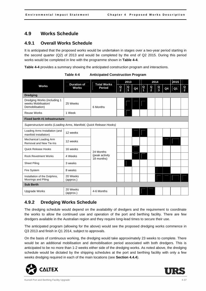
E n v i r o n m e n t a l I m p a c t S t a t e m e n t C h a p t e r 4 P r o p o s e d W o r k s D e s c r i p t i o n
Kurnell Port and Berthing Facility Upgrade 4-37
4.9 Works Schedule
4.9.1 Overall Works Schedule It is anticipated that the proposed works would be undertaken in stages over a two-year period starting in the second quarter (Q2) of 2013 and would be completed by the end of Q2 2015. During this period works would be completed in line with the programme shown in Table 4-4.
Table 4-4 provides a summary showing the anticipated construction program and interactions.
Table 4-4 Anticipated Construction Program
Works Duration of Works
Total Works Period
2013 2014 2015 Q2
Q3 Q4 Q
1 Q2
Q3 Q4 Q1 Q
2 Dredging Dredging Works (including 1 weeks Mobilisation/ Demobilisation)
25 Weeks 6 Months
Reuse Works 1 Week
Fixed berth #1 Infrastructure
Superstructure works (Loading Arms, Manifold, Quick Release Hooks)
Loading Arms Installation (and
manifold installation) 12 weeks
24 Months (peak activity 18 months)
Mechanical Loading Arm
Removal and New Tie-Ins 12 weeks
Quick Release Hooks 16 weeks
Rock Revetment Works 4 Weeks
Sheet Piling 3 weeks
Fire System 8 weeks
Installation of the Dolphins, Moorings and Piling
20 Weeks (approx.)
Sub Berth
Upgrade Works 20 Weeks (approx.)
4-6 Months
4.9.2 Dredging Works Schedule The dredging schedule would depend on the availability of dredgers and the requirement to coordinate the works to allow the continued use and operation of the port and berthing facility. There are few dredgers available in the Australian region and they require long-lead times to secure their use.
The anticipated program (allowing for the above) would see the proposed dredging works commence in Q3 2013 and finish in Q1 2014, subject to approvals.
On the basis of continuous working, the dredging would take approximately 23 weeks to complete. There would be an additional mobilisation and demobilisation period associated with both dredgers. This is anticipated to be no more than 1-2 weeks either side of the dredging works. As noted above, the dredging schedule would be dictated by the shipping schedules at the port and berthing facility with only a few weeks dredging required in each of the main locations (see Section 4.4.4).
C h a p t e r 4 P r o p o s e d W o r k s D e s c r i p t i o n E n v i r o n m e n t a l I m p a c t S t a t e m e n t
4-38 Kurnell Port and Berthing Facility Upgrade
4.9.3 Fixed Berth Upgrade Works Schedule
The final construction schedule for the proposed fixed berth upgrade works would depend on a number of factors including the finalised design, the works’ contractors detailed works program and equipment delivery and availability.
Anticipated construction would take approximately 24 months to complete (with the majority of the works
taking place over an 18 month period). The works would be completed under the following, generally sequential, stages:
piping, loading arms and quick release hook delivery;
prefabrication of manifold and sections of pipe;
site preparation, blinding10 and water washing to gas free redundant lines;
removal of redundant lines, manifold, loading arms and bollards;
delivery and installation of spools, manifold, loading arms and quick release hooks;
commissioning of loading arms and quick release hooks; and
installation of the new fire system.
The installation of the sheet pile wall/rock revetment would be undertaken in parallel with the above works over a 7 week period.
4.9.4 Sub Berth Upgrade Works Schedule
Upgrading the sub berth whilst it is shut down would take 4 months to complete. Upgrading the sub berth, whilst allowing it to operate at the same time, would take 6 months to complete.
4.9.5 Peak Construction The works’ program has been designed to prevent intensive works occurring concurrently where possible. Whilst there is no specific peak construction period (see Table 4-4) there are a number of periods during the overall program where works would coincide. The two noted points are:
Q4 2013, where the dredging works would coincide with the replacement of the loading arms, the rock revetment works and installation of quick release hooks on fixed berth #1; and
Q1 2014, where the dredging works would coincide with the replacement of the loading arms, the rock revetment works and the upgrade of the sub berth.
These noted construction periods have been used to assess the worst-case conservative scenario in terms of the combination of noise and vibration impacts (see Chapter 13, Noise), air emissions (see Chapter 14, Air Quality and Odour) and general disturbance (amenity) (see Chapter 17, Amenity, Land Use, Recreation and Navigation).
10 The process by which a steel plate is inserted between two flanges or a valve is closed to isolate product and maintain safety of personnel.

E n v i r o n m e n t a l I m p a c t S t a t e m e n t C h a p t e r 4 P r o p o s e d W o r k s D e s c r i p t i o n
Kurnell Port and Berthing Facility Upgrade 4-39
Table 4-5 sets out an indicative list of substantial equipment that would be used during construction. Alternative equipment may be used depending on the development of the final detailed design, contractor
specifications and availability.
Table 4-5 Construction Equipment List
Activity Equipment List No Notes
Dredging Dredging Works BHD (with associated
lifting arms compressors and generators)
1 -
Dredging Works Split Hopper 2 (4) Up to four will be used however only two will be located within the dredge footprint at any one time.
Safety and manoeuvring
Tugboat 3 (5) Required to manoeuvre and support the BHD and split hopper. NB: 2 additional tugboats would be in transit to and from the disposal ground.
Supply Launch/Supply Ship 2 Intermittent and required to supply the ships undertaking the works and to switch dredging crews.
Fixed Berth Upgrade (including Rock Revetment and Sheet Piled Wall) Piling Works (Fixed Berth)
Rock Hammer 1 Required to pile the tubular steel piles. Vibratory Pile 1
Jack Up Barge (with associated diesel generators)
1 To undertake the piling works.
Welding, cutting and grinding equipment and water pump.
Various Required to remove the existing structures.
Small Mobile Crane/Barge Mounted Crane
1 To manoeuvre and position the tubular steel piles into position.
Stone Placement (Rock Revetment)
BHD (with associated lifting arms compressors and generators)
1 Required to unload the stone.
Transport of Stone (Rock Revetment)
Barges 2 Required to transport the stone.
Tugboat 2 Required to manoeuvre the hopper.
Replacement of the bollards
Grinding and cutting equipment and power generators
Various Requirement to remove the existing equipment.
Loading Arms (installation and decommissioning)
Mobile Crane 2(1) Installation (and decommissioning) of loading arms. Tug Boats 4(2)
Grinding and cutting equipment and power generators
Various
Removal or exiting preventer lines, installation of QRH, replacement of mooring chains
Auxiliary Boats 3 Required to coordinate the works off the Wharf.
Grinding and cutting equipment and power generators.
Various Requirement to remove and install equipment.
Fire System Installation
Mobile Crane 1 To deliver and install new equipment.
Tug Boats 2

C h a p t e r 4 P r o p o s e d W o r k s D e s c r i p t i o n E n v i r o n m e n t a l I m p a c t S t a t e m e n t
4-40 Kurnell Port and Berthing Facility Upgrade
Activity Equipment List No Notes
Grinding and cutting equipment and power generators.
Various Requirement to remove and install equipment.
Sheet Piled Wall Pile Rig (with rig power pack and water jet pump)
1 Required to install the sheet piled wall.
Delivery (General)
Delivery Barge 1 Intermittent to deliver tubular steel piles and equipment.
Support (General) Dive Boat 1 Required to oversee the piling works.
Supply (General) Boat 1 Required to deliver the piles and equipment.
Sub Berth Upgrade Sub Berth Upgrade
Barge (with associated crane, compressors and generators (see Section 4.5.2))
1 Used to undertake the majority of the works in the sub berth.
Safety and delivery
Tugboat 1 To locally manoeuvre around the sub berth and facilitate delivery of equipment to the project site.
Supplies Crew Ship 1 To allow shift working.
Support Dive Boat 1 To provide dive support to the operations.
4.9.6 Proposed Working Hours The majority of the works would be undertaken within the standard working hours defined by the Interim Construction Noise Guidelines (ICNG), namely Monday-Friday 0700-1800 and Saturday 0800-1300 with the exception of the following.
Dredging Works
The proposed duration of the works has been minimised to limit the impact on the operational shipping channel, berthing and unloading at the Kurnell Wharf. To achieve this in a minimal timeframe, it is
proposed that the dredging would be undertaken on a continuous basis (24-hours per day). The dredger would operate within the constraints of the port and berthing facility shipping schedule. This may require short periods when the dredger is stood down from operating in a specific area. The dredger would either
stop works, head in for scheduled maintenance, or most likely move to another unaffected area of the footprint. In addition, there would be a period during any given week when the dredger would need to be serviced, refuelled and maintained. This would equate to approximately one-lost day to dredging each
week.
Sub-Berthing Upgrade
The sub berth upgrade would take place 7 days per week between the hours of 0700h-1800h. However, certain works within this period would be constrained to standard working hours set by the Interim
Construction Noise Guideline 200911. This is discussed further in Chapter 13, Noise.
11 The above Guideline states standard working hours to be Monday-Friday 0700h-1800h and Saturday 0800h-1300h.
E n v i r o n m e n t a l I m p a c t S t a t e m e n t C h a p t e r 4 P r o p o s e d W o r k s D e s c r i p t i o n
Kurnell Port and Berthing Facility Upgrade 4-41
4.9.7 Employment
The works would generate a low transient construction work force. Caltex has a number of existing contracts with boat and dive specialists that would undertake elements of the proposed works. The works are anticipated to include the following staffing requirements.
The dredgers and associated tugboats come with manned and trained crews, which would total approximately 30 people working in three 8-hour shifts.
The works at the fixed berths are anticipated to require approximately 25 construction staff working in teams of one to three.
The upgrade of the sub berth would require a team of 12 (five personnel on the barge, two people to man the tugboat, one person to man the crew boat and a dive-team comprising four personnel).
4.10 Ongoing Facility Operations Once completed, the upgraded port and berthing facility would continue to operate in a similar manner as present. Operations at the facility would be unchanged following the upgrade, with the same permits and licences remaining in place to manage and control the environmental operations.
The replacement and upgraded infrastructure is consistent with current licence provisions and of the same scale and size as the existing infrastructure. There would be no anticipated change in personnel following the upgrade.
During the operational life of the project there may be a requirement to undertake additional ongoing maintenance dredging of the area. Caltex would be permitted to undertake this pursuant to the terms of the Australian Oil Refining Agreements Act 1954 and the State Environmental Planning Policy (SEPP) Infrastructure 2007 as discussed in Chapter 5, Legislation and Planning Policy Context.
The only material change in operation would be a reconfiguration of the berthing. Whilst no larger ships would enter the port and berthing facility than at present, the reconfiguration would provide the flexibility of being able to berth larger ships in fixed berth #1 than at present and the ability to berth various sized ships in the sub berth than at present. It is predicted that this flexibility would see a reduction in overall shipping arriving at the facility by approximately 40% in 2020 (compared to 2011 figures) following the proposed works.
The limited scope of the operational assessment included in the EIS reflects the limited operational changes envisaged. Relevant assessments have been included within the technical assessment chapters (see Chapters 7-18), with any additional mitigation and management measures included where necessary.
4.11 Facility Decommissioning The proposed works would extend the operational life of the port and berthing facility by 50 years. Towards the end of this period a decision would be taken whether to once again increase the facility’s operational life or to cease its operation and decommission the facility. Decommissioning may include partial or full removal of the port and berth facility infrastructure. It would also likely result in the sealing and capping any associated subsea pipelines. The subsea structures may either be removed and/or remain in situ.

C h a p t e r 4 P r o p o s e d W o r k s D e s c r i p t i o n E n v i r o n m e n t a l I m p a c t S t a t e m e n t
4-42 Kurnell Port and Berthing Facility Upgrade
All decommissioning activities would be in accordance with applicable Commonwealth, State and local permits and requirements and would be completed in accordance with existing NSW EPA licences and the relevant extant legislation and safeguards at the time.
4.12 Capital Investment Value of All Works The capital investment value of the works, as determined by the supporting Quantity Surveyors Report (see Technical Appendix J), is anticipated to be $66.2 million.
E n v i r o n m e n t a l I m p a c t S t a t e m e n t C h a p t e r 5 L e g i s l a t i o n a n d P l a n n i n g P o l i c y
C o n t e x t
Kurnell Port and Berthing Facility Upgrade 5-1
5 Legislation and Planning Policy Context
5.1 Introduction
The following chapter considers how the proposed works comply or conflict with relevant legislation and
planning policy that governs development, provides environmental protection and implements health and
safety controls in NSW, and where relevant, Australia.
Relevant legislation and planning policy has been also used to set assessment parameters, guide
assessment methods, define threshold limits and set assessments of significance.
5.2 Overall Development Context
The works classify as ‘development’ under the Environmental Planning and Assessment Act 1979 (EP&A
Act). This Act regulates development within NSW.
The development application (DA) and consent process is defined by the nature and type of development
proposed. In the case of the proposed works, as their capital value exceeds the $30 million limit set for
port and wharf facility development included under Section 18, Schedule 1 of the State Environmental
Planning Policy (SEPP) on State and Regional Development (SRD) 2011, they classify as State
Significant Development (SSD).
Development consent for the proposed works is therefore being sought under Clauses 69(1) and 69(3) of
the SEPP Infrastructure 2007. In order to comply with the EP&A Act, an environmental impact statement
(EIS) must be prepared and submitted alongside the DA. Schedule 2 of the EP&A Regulation sets out
what should be included in preparing the EIS (see Sections 5.4.2 and 5.5.1).
The provisions of the SEPP on SRD were put in place to ensure that such development is determined at
the State level. The Minister for Planning and Infrastructure remains the determining authority for SSD.
However, where there are more than 25 objections to the application, the relevant local council has
objected or the applicant has made a political donation, these powers are delegated to the Planning
Assessment Commission (PAC), an independent body created to provide impartiality to the planning
approvals process in such instances.
In order to assist in the preparation of this EIS an environmental scoping assessment (ESA) has been
prepared on behalf of Caltex. The ESA was submitted to NSW Department of Planning and Infrastructure
(DP&I) in June 2012, with the Director General’s Requirements (DGRs) issued on 9 August 2012.
Beyond the primary legislation governing development in NSW are a range of Commonwealth, State and
local planning provisions and policies that would be relevant to the proposed works. These are discussed
below.
5.3 Commonwealth Requirements
5.3.1 Overview
The proposed works would need to consider the provisions of the following Commonwealth Acts:
• Environment Protection and Biodiversity Conservation Act 1999 (EPBC Act); and
• Environment Protection (Sea Dumping) Act 1981 (Sea Dumping Act).
C h a p t e r 5 L e g i s l a t i o n a n d P l a n n i n g P o l i c y C o n t e x t
E n v i r o n m e n t a l I m p a c t S t a t e m e n t
5-2 Kurnell Port and Berthing Facility Upgrade
5.3.2 Environment Protection and Biodiversity Conservation Act
The EPBC Act requires that a proposed development (termed an ‘action’) that has, will have, or is likely to
have a significant impact on a matter of national environmental significance (MNES) may not be
undertaken without prior approval of the Commonwealth Minister for the Department of Sustainability,
Environment, Water, Population and Communities (SEWPAC).
MNES are defined as:
• world heritage sites;
• national heritage places;
• wetlands of international importance (including Ramsar wetlands);
• nationally threatened species and ecological communities;
• migratory species;
• Commonwealth marine areas;
• the Great Barrier Reef Marine Park;
• actions on Commonwealth land; and
• nuclear actions.
The project site and its immediate environs do not include any world heritage sites, Commonwealth
marine areas, the Great Barrier Reef Park or Commonwealth land. The proposed works also do not form
part of a nuclear action.
The following MNES are however of relevance and have been considered in the EIS:
• Captain Cooks landing place located in Kamay Botany Bay National Park (see Chapter 12,
Heritage);
• Towra Point Nature Reserve, a designated Ramsar wetland (see Chapter 11, Ecology); and
• a number of migratory and threatened species and ecological communities (see Chapter 11,
Ecology).
The Matters of National Environmental Significance: Significant Impact Guidelines 1.1 (EPBC Guidelines)
set out criteria to assess whether an ‘action’ is controlled under the EPBC Act and therefore requires
Commonwealth Ministerial approval. In particular, the EPBC Guidelines contain criteria for assessing
whether the action is likely to have a significant impact on a MNES. These criteria are known as
significant impact criteria (SICs).
Several heritage lists are also addressed by the EPBC Act, including the National Heritage List (NHL).
The NHL protects places that have outstanding value to the nation.
In instances where the applicant believes there will be a significant impact, or where there is any
uncertainty, a referral is made to the Commonwealth Minister for SEWPAC, to confirm whether the
proposed works constitute a ‘controlled action’.
Through the process of environmental assessment (EA) it has been concluded that it is unlikely that the
proposed works would cause a significant impact on any MNES therefore negating the requirement for

E n v i r o n m e n t a l I m p a c t S t a t e m e n t C h a p t e r 5 L e g i s l a t i o n a n d P l a n n i n g P o l i c y C o n t e x t
Kurnell Port and Berthing Facility Upgrade 5-3
either a referral or approval from the Commonwealth Minister for SEWPAC (see Chapter 11, Ecology and Chapter 12, Heritage).
5.3.3 Environment Protection (Sea Dumping) Act The Sea Dumping Act regulates the offshore disposal of certain materials through sea dumping. It applies to the majority of Australia’s marine waters out to the limit of the exclusive economic zone (EEC); 200 nautical miles from the coast.
It implements Australia’s obligations under the Protocol to the Convention on the Prevention of Marine Pollution by Dumping of Wastes and Other Matters 1972 (the London Protocol). It requires that a sea dumping permit (SDP) be obtained from SEWPAC prior to being able to ‘load and dispose’ of materials by sea dumping.
The National Assessment Guidelines for Dredging (NAGD) 2009 are intended to assist applicants under the Sea Dumping Act by providing a comprehensive framework for the assessment of the environmental impacts from the disposal of sea of dredged material.
The Sea Dumping Act requires the applicant undertake detailed sampling and analysis of the materials that are proposed for disposal and consider alternatives to sea dumping, which is the last option promoted by the Sea Dumping Guidelines that support this Act. Where sea dumping is proposed, there is a further requirement to assess the likely impacts on the receiving environment.
The SDP application is being progressed in parallel to the DA. It was submitted to the Commonwealth in November 2012. The studies that support the SDP have been used to inform some of the EIS technical assessments (see Chapter 9, Spoil and Contamination and Chapter 10, Water and Sediment Quality).
5.4 State Legislation
5.4.1 Introduction The proposed works would be subject to the provisions of the following state Acts and Regulations:
Environmental Planning and Assessment Act 1979 and the Environmental Planning and Assessment Regulation 2000;
Maritime Services Act 1935;
Australian Oil Refining Agreements Act 1954;
Management of Waters and Waterside Lands Regulations;
National Parks and Wildlife Act 1974 (as amended);
Heritage Act 1977;
Fisheries Management Act 1994;
Threatened Species Conservation Act 1995;
Protection of the Environment Operations Act 1997;
Contaminated Land Management Act 1997;
Marine Safety Act 1998;
C h a p t e r 5 L e g i s l a t i o n a n d P l a n n i n g P o l i c y C o n t e x t E n v i r o n m e n t a l I m p a c t S t a t e m e n t
5-4 Kurnell Port and Berthing Facility Upgrade
Water Management Act 2000 (as amended);
Work Health and Safety Act 2011; and
Marine Pollution Act 2012.
5.4.2 Environmental Planning & Assessment Act (EP&A Act) and EP&A Regulation
This EIS has been prepared in accordance with the following key provisions of the EP&A Act and the EP&A Regulation.
Section 78(A) (8A) of the EP&A Act, which states that a ‘DA for SSD is to be accompanied by an EIS prepared by or on behalf of the applicant in the form prescribed by the regulations’.
Section 79(C) of the EP&A Act, which identifies general matters that NSW DP&I is to take into consideration when determining a DA. These include:
– relevant environmental planning instruments, development control plans or planning agreements, and their applicability to the proposed works;
– whether the works satisfy the requirements of the EP&A Regulation;
– any impact or conflict with a coastal management plan;
– whether the likely environmental, social and economic impacts resulting from the proposed works are acceptable;
– the continued suitability for the project site to operate as a port and berthing facility;
– any formal submission relating to the proposed works as prescribed under the EP&A Act or the EP&A Regulation; and
– wider public interests.
Schedule 2 of the EP&A Regulation, which specifies the minimum requirements that need to be included in an EIS (as set out in Chapter 1, Introduction).
Section 89(J) of the EP&A Act outlines authorisations that are not required for SSD and Section 89(K) sets out the authorisations that cannot be refused if required for carrying out SSD. The following authorisations are relevant to the proposed works.
Authorisations not required under SSD include:
– Concurrence under Part 3 of the Coastal Protection Act 1974;
– A permit under section 201, 205 or 219 of the Fisheries Management Act 1994 relating to undertaking dredging or reclamation works or harming marine vegetation in a protected area;
– An approval under Part 4, or an excavation permit under Section 139, of the Heritage Act 1977;
– An Aboriginal Impact Permit under Section 90 of the National Parks and Wildlife Act 1974;
– An authorisation referred to in Section 12 of the Native Vegetation Act 2003 to clear native vegetation or stated protected land.
E n v i r o n m e n t a l I m p a c t S t a t e m e n t C h a p t e r 5 L e g i s l a t i o n a n d P l a n n i n g P o l i c y C o n t e x t
Kurnell Port and Berthing Facility Upgrade 5-5
Authorisations that cannot be refused:
– An Environmental Protection Licence (EPL) under the terms of the Protection of the Environment Operations Act 1997.
Other requirements of the above Acts are discussed in more detail below.
5.4.3 Maritime Services Act The Maritime Division of NSW Roads and Maritime Services (RMS) manage, amongst other things, the coastal waters of NSW. The State has devolved responsibility to NSW RMS to care for the management of a number of matters including marine safety in NSW, regulation of commercial and recreational boating and property management, which involves overseeing its appropriate use and development. The responsibilities and powers of NSW RMS are set out in the above Maritime Services Act.
The Maritime Services Act remains relevant to the proposed works as it has required Caltex to obtain landowners’ consent from NSW RMS prior to lodgement of the DA (obtained on 17 November 2012). It also requires that Caltex obtain a licence to dredge the seabed from NSW RMS prior to starting the proposed works.
5.4.4 Australian Oil Refining Agreements Act (AORA Act) The AORA Act was gazetted to facilitate the construction and operation of the Kurnell Refinery. The
AORA Act permits the dredging of Botany Bay to secure safe access to wharves and other works. The Act also allows certain infrastructure works to take place within the Bay to support the Refinery.
5.4.5 The Management of Waters and Waterside Lands Regulations (MWWL Regulations)
The MWWL Regulations are formed under the Maritime Services Act. They define Special Port Areas in NSW. Botany Bay is listed as a Special Port Area.
Activity and development within a Special Port Area is controlled under these Regulations. Specific port authorities have been set up to administer the terms of the Maritime Services Act through these Regulations. In the case of Botany Bay, the relevant port authority is Sydney Ports Corporation (SPC).
Ahead of undertaking the proposed works, there is a requirement to obtain Harbour Master Approval from SPC.
Harbour Master approval is being sought in parallel with the DA. Harbour Master Approval requires that a description of the proposed works be provided along with information on the intended disturbance to the seabed, any intention to remove marine vegetation and the requirement to install any moorings and/or port installations. All are relevant considerations for SPC given the nature of the proposed works.
The EIS is also provided as a basis on which SPC would consider its approval. SPC is entitled to impose conditions that limit the disturbance of the seabed. These may be in addition to any conditions of consent issued following approval of the DA.

C h a p t e r 5 L e g i s l a t i o n a n d P l a n n i n g P o l i c y C o n t e x t E n v i r o n m e n t a l I m p a c t S t a t e m e n t
5-6 Kurnell Port and Berthing Facility Upgrade
5.4.6 The National Parks and Wildlife Act (NP&W Act) Under the NP&W Act the NSW National Parks and Wildlife Service (NPWS) (part of the Office of Environment and Heritage (OEH)) is responsible for the care, control and management of all national parks, historic sites, (nature and game state) reserves, Aboriginal areas, state conservation areas and regional parks. Two relevant aspects of this Act that relate to the proposed works are discussed below.
The Protection of Flora and Fauna
The NP&W Act administers the protection of flora and fauna. It makes it an offence to harm any animal, threatened species, population or community that is protected under the NP&W Act. It also enables the creation of State-protected sites of ecological value. The applicable provisions of this Act and relevant State-protected sites of ecological value have been considered in the ecological assessment that has informed this EIS (see Chapter 11, Ecology).
Aboriginal Heritage
In addition, the NP&W Act provides for the conservation of objects, places or features of cultural value. It makes it an offence to knowingly destroy, deface, damage, or cause or permit the destruction or defacement of or damage to an Aboriginal object or place without the necessary consent.
Aboriginal places and objects protected under this Act are registered on the Aboriginal Heritage Information System (AHIMS). The Aboriginal heritage provisions of the NP&W Act have been considered in this EIS (see Chapter 12, Heritage). As the proposed works are SSD there is no requirement to apply for approval under the NP&W Act.
5.4.7 The Heritage Act The Heritage Act aims to conserve the cultural heritage of NSW, including Aboriginal cultural heritage, principally through the establishment of a State Heritage Register (SHR), Heritage and Conservation Register (HCR), and the NSW Maritime Heritage Shipwreck Database (MHSD). It also enables interim heritage orders to be made to protect heritage items or places. This Act details statutory responsibilities for the protection of historic buildings, places and objects and archaeological sites. It also sets out the criteria for recognising and listing Aboriginal places or objects on the SHR.
This Act makes it an offence to damage and modify heritage items without approval of the NSW Heritage Council. This Act also enables a list of heritage items to be developed; a process that is managed by the NSW Heritage Council.
This Act also covers maritime archaeology. Should physical remains of a shipwreck or other maritime heritage be identified whilst works are being carried out there is a requirement to cease work and notify the NSW Heritage Council, as included as a mitigation measure of this EIS (see Table 12-5).
The statutory requirement to report Aboriginal and historic heritage finds has been carried through into the commitments set out in this EIS along with the consideration of any potential impact on Aboriginal places and objects, heritage items and/or maritime archaeology (see Chapter 12, Heritage). As the proposed works are SSD there is no requirement to apply for approval or excavation permit under this Act.
The proposed works have been assessed as having a limited potential impact on any heritage items limiting the relevance of the Heritage Act.
E n v i r o n m e n t a l I m p a c t S t a t e m e n t C h a p t e r 5 L e g i s l a t i o n a n d P l a n n i n g P o l i c y C o n t e x t
Kurnell Port and Berthing Facility Upgrade 5-7
5.4.8 The Fisheries Management Act (FM Act) The FM Act concerns the conservation, development and sharing of the State’s fishery resources for the benefit of present and future generations. It provides for the conservation of biological diversity in relation to aquatic and marine vegetation. It also ensures that the impact of any ‘action’ affecting threatened species, populations or ecological communities is appropriately assessed.
Schedules to this Act provide the listings of aquatic threatened species, populations and ecological communities that have been considered in the ecological assessment forming part of this EIS (see Chapter 11, Ecology).
Relevant to the proposed works are the provisions of Section 197D of the FM Act. This section requires DP&I, as the determining authority, to take into account the impacts of the proposed development on the Towra Point Aquatic Reserve and consult with the Minister should an impact be likely. The relevance of this provision to the determination of the proposed works is discussed further in Chapter 11, Ecology.
There is no requirement to obtain a separate licence for the dredging component of the proposed works under the FM Act.
5.4.9 Threatened Species Conservation Act (TSC Act) The TSC Act gives legal status for threatened flora and fauna, populations and ecological communities of conservation significance in NSW. The core aim of this Act is to ‘conserve biological diversity and promote ecologically sustainable development’. This Act provides a framework for the assessment of any action that may impact on threatened species, populations or communities.
The TSC Act covers:
protection of ‘threatened species, populations and ecological communities’, with ‘endangered species, populations and communities’ listed under Schedule 1, ‘critically endangered species and communities’ listed under Schedule 1A, and ‘vulnerable species and communities’ listed under Schedule 2;
identification of key threatening processes (KTPs) listed under Schedule 3;
preparation and implementation of recovery plans and threat abatement plans;
guidelines for the preparation of species impact statements (SIS); and
listing of identification of critical habitat for threatened species.
The ecological assessment that forms part of this EIS has adopted the assessment requirements of this Act in its assessment of significance on threatened biota (see Chapter 11, Ecology). This has included considering the list of terrestrial threatened biota contained within the schedules of this Act.
5.4.10 Protection of the Environment Operations Act (POEO Act) The POEO Act provides for controls and licencing provisions to protect the environment, reduce pollution, and manage the storage, treatment and disposal of waste. A key feature of this Act is the issuing of Environmental Protection Licences (EPLs) for certain (scheduled) activities.

C h a p t e r 5 L e g i s l a t i o n a n d P l a n n i n g P o l i c y C o n t e x t E n v i r o n m e n t a l I m p a c t S t a t e m e n t
5-8 Kurnell Port and Berthing Facility Upgrade
The Kurnell Refinery (which includes the ‘shipping in bulk’ facilities) operates under EPL licence number 837. The EPL specifies limits for volumes involved in bulk shipping as well as emissions and requirements for managing and controlling noise, air quality, dust and waste emissions. All are relevant to the proposed works and have been discussed and considered in the relevant chapters and technical appendices that form part of this EIS.
It is proposed that works would be carried out under the terms of the existing EPL No. 837. This includes the provisions of the EPL relating to shipping in bulk. As there would be no planned change in total volumes exported or imported from the site, no variation to the EPL No. 837 would be required for the proposed works.
There would be no requirement to obtain a separate EPL for the reuse of ‘an extractive material’ as scheduled activity under this Act. A licence under Section 120 of the POEO Act would be obtained to allow the disposal of sediments within the Bay (see Chapter 9, Water and Sediment Quality).
5.4.11 Contaminated Land Management Act (CLM Act)
The general objective of the CLM Act is to establish a process for investigating, and where appropriate, remediating land that is considered to pose a significant risk to human health or the environment. This Act is relevant in assessing the suitability of the dredged sediments for onshore disposal. As onshore
disposal has not been carried forward as an option (see Chapter 8, Spoil and Contamination) this Act has not been considered further in this EIS.
5.4.12 Marine Safety Act (MS Act) The MS Act sets out the requirements for marine safety as well as the roles and obligations of Harbour Masters and Marine Pilots. The MS Act contains important provisions relating to marine and navigational and boating safety including:
regulations for the prevention of collisions;
speed limits and no-wash zone areas;
restrictions on the operation of ships;
reckless, dangerous or negligent navigation;
protection of navigation aids;
approvals required for aquaculture leases over navigable waters;
regulations for organised aquatic activities; and
regulations relating to the safety of navigation.
These navigation and safety provisions have been adopted within the mitigation and management measures for the proposed works.

E n v i r o n m e n t a l I m p a c t S t a t e m e n t C h a p t e r 5 L e g i s l a t i o n a n d P l a n n i n g P o l i c y C o n t e x t
Kurnell Port and Berthing Facility Upgrade 5-9
5.4.13 Water Management Act (WM Act) The WM Act as amended establishes a framework for managing water in NSW. The component of the Act relevant to the proposed works is the requirement to obtain an aquifer interference approval where:
there is a penetration of an aquifer;
the interference of water in an aquifer; and/or
the obstruction of the flow of water in an aquifer.
It is an offence to either carry out works without such an approval or cause harm to an aquifer.
In September 2012, the NSW Government released the NSW Aquifer Interference Policy (DPI, 2012). This policy clarifies the requirements for obtaining water licences for aquifer interference activities under NSW water legislation (the WM Act); and establishes and objectively defines considerations in assessing and providing advice on whether more than minimal impacts might occur to a key water-dependent asset. This policy does not apply to the proposed works as there would be no interference with groundwater and therefore an aquifer (see Chapter 10, Water and Sediment Quality).
5.4.14 Work Health and Safety Act (WH&S Act) The WH&S Act and its supporting Regulation 2011 include measures to prevent accidents occurring at major hazard facilities (MHF).
The Kurnell Refinery port and berthing facility classify as a MHF. Any works to, or modifications of, a MHF require the consent and approval of WorkCover NSW as the administrators of this Act.
WorkCover NSW has been informed of the proposed upgrade of the Kurnell port and berthing facility to account for the hazards and risks associated with the proposed works.
The notification process has required Caltex to demonstrate that suitable controls would be implemented to prevent the occurrence of a major accident. To do this, Caltex is required to prepare a risk assessment for the proposed works identifying the associated hazards. Caltex is also required to submit a safety case that can demonstrate that appropriate safety management systems and emergency and security plans are in place.
5.4.15 Marine Pollution Act (MP Act) The MP Act sets out requirements to protect NSW’s maritime environment from pollution caused by recreational, trading and commercial ships operating in NSW waters. The main aim of this act is to implement the International Convention for the Prevention of Pollution from Ships (MARPOL) 1978.
The MP Act specifically addresses:
oil pollution;
noxious liquids;
pollution by harmful substances carried in packaged form;
sewage;
garbage; and
air pollution.
C h a p t e r 5 L e g i s l a t i o n a n d P l a n n i n g P o l i c y C o n t e x t E n v i r o n m e n t a l I m p a c t S t a t e m e n t
5-10 Kurnell Port and Berthing Facility Upgrade
The MP Act is important to the proposed works as it sets out provisions that can indirectly affect the quality, enjoyment, use and viability of marine resources for recreational, community and commercial purposes.
The implications of the MP Act have been considered in the mitigation measures for the proposed works (see Table 17-3).
5.5 State and Local Planning Policy
5.5.1 State Environmental Planning Policies SEPPs deal with issues significant to the state of NSW. The proposed works would be subject to the provisions of the following SEPPs:
SEPP Kurnell Peninsula 1989;
SEPP No 33: Hazardous and Offensive Development 1992;
SEPP No 55: Remediation of Land 1998;
SEPP No 14: Coastal Wetlands 2000;
SEPP No 62: Sustainable Aquaculture 2000;
SEPP No 71: Coastal Protection 2002;
SEPP Infrastructure 2007; and
SEPP on State and Regional Development 2011.
SEPP Kurnell Peninsula 1989
This SEPP aims to conserve the natural environment of the Kurnell Peninsula and ensure that development is managed having regard to the environmental, cultural and economic significance of the area to the nation, state, region and locality. This SEPP applies to the land within Sutherland Shire, known as the Kurnell Peninsula, and adjacent waterways.
The south east corner of the extended fixed berth #1 and laydown and loading areas would be located within the limits of this SEPP.
The following provisions within this SEPP are relevant to the proposed works.
Zone No 7 (a) (The Waterway Zone)
The Waterway Zone is defined under Part 2(9) of this SEPP. It covers the offshore area between the headlands of Kamay Botany Bay National Park to the east and Woolooware Bay to the west. It includes the whole of Silver Beach and the majority of the Kurnell Wharf (see Figure 5-1). As noted above, a small portion of the proposed works would take place within this area.
The Waterway Zone is categorised as a prescribed zone under Division 13 of SEPP Infrastructure 2007, which identifies the proposed dredging works as a permissible form of development requiring development consent under clauses 69(1) and 69(3) of SEPP Infrastructure 2007.
The objectives of the Waterway Zone are to protect, enhance, conserve and maintain aquatic ecosystems and industries. This SEPP states consent shall not be granted to the carrying out of development on land adjacent to, or adjoining, the Waterway Zone.

E n v i r o n m e n t a l I m p a c t S t a t e m e n t C h a p t e r 5 L e g i s l a t i o n a n d P l a n n i n g P o l i c y
C o n t e x t
Kurnell Port and Berthing Facility Upgrade 5-11
Wetland Protection
Section 21 of this SEPP requires that consideration be given to the environmental impacts of
development on the long-term viability of the wetland areas covered by the SEPP including their
ecosystems and biota. This includes impacts on the Towra Point Nature and Aquatic Reserves located
west of the project site. The ecological assessment that forms part of this EIS has considered impacts on
the condition and status of these sites as a result of the proposed works (see Chapter 11, Ecology).
Heritage
Sections 23(A)-23(D) of this SEPP require that items and places of Aboriginal and historic heritage are
protected from the impacts arising from development. Schedule 2 and Schedule 3 list archaeological sites
and heritage items covered by this SEPP. Of relevance to the proposed works are the Kurnell Peninsula
Headland, the Australian Oil Refinery (including the Kurnell Wharf), Bonna Point Reserve, the Crown
Land Boatshed, and the Silver Beach Roadway. All items have been considered in the heritage
assessment that forms part of this EIS (see Chapter 12, Heritage).
Protection of Coastal Areas
Section 27 of this SEPP sets out the provisions that Sutherland Shire Council is required to complete
prior to granting consent to land affected, or likely to be affected, by coastal processes.
This includes the need to consult with the Director General of the Department of Finance and Services
and Commissioner of the Soil Conservation Service of NSW, and take in to consideration their comments
on any proposed development. The Council is also required to set a condition of consent that any
disturbed foreshore areas are rehabilitated and that access across the foredune areas be confined to
specified points.
Impacts on the foreshore area have been considered as part of the hydrological assessment that forms
part of this EIS including the need for rehabilitation (see Chapter 8, Hydrodynamics and Coastal
Process). Access across the foredune areas is not required to execute the proposed works. The opinions
of Sutherland Shire have been considered in this EIS through ongoing consultation (see Chapter 6,
Consultation).
SEPP No 33: Hazardous and Offensive Development
This SEPP outlines the approach used in NSW for planning and assessing industrial development
proposals that include hazards or offensive components. Through this policy, the permissibility of an
industrial proposal is linked to its safety and pollution control performance.
This SEPP applies to any proposals that fall under the policy’s definition as potentially hazardous or
offensive industry. As the proposed works relate to the upgrade of refinery infrastructure they qualify
under this definition.
For such proposals, this SEPP establishes a comprehensive test by way of a preliminary hazard analysis
(PHA) to determine the risk to people, property and the environment at the proposed location of the
development and in the presence of controls.
The policy defines potentially hazardous industry as ‘a development for the purposes of any industry
which, if the development were to operate without employing any measures (including, for example,
isolation from existing or likely future development on other land) to reduce or minimise its impact in the
locality or on the existing or likely future development on other land, would pose a significant risk in
relation to the locality’.

C h a p t e r 5 L e g i s l a t i o n a n d P l a n n i n g P o l i c y C o n t e x t
E n v i r o n m e n t a l I m p a c t S t a t e m e n t
5-12 Kurnell Port and Berthing Facility Upgrade
A PHA has been prepared as part of the technical assessments to support this EIS (see Chapter 15,
Hazards and Risk Assessment and Technical Appendix I). The PHA considers the actions of the
proposed development in relation to any hazards and risks to the existing port and berthing facility. The
PHA has been prepared in accordance with the NSW Hazardous Industry Planning Advisory Papers
(HIPAPs), which set out the methods required to complete a PHA.
SEPP No 55: Remediation of Land
This SEPP requires that a consent authority consider the suitability of land for a proposed development.
Ultimately, a consent authority needs to be satisfied that a site is suitable for its proposed use or can and
will be made suitable, based on what they know of the site. This will involve an evaluation or review of the
information submitted by the applicant as part of the DA.
With regards to the proposed works they are taking place ‘on land’ that is not notified as being
contaminated under the Contaminated Land Management Act 1997. However, the project site does
contain contaminated sediments (see Chapter 10, Water and Sediment Quality). Accordingly, the
provisions of this SEPP have been considered from the perspective of: setting out the suitability of the
site for its continued use as a port and berthing facility, mindful of the proposal to dredge these
sediments; the consideration as to whether onshore disposal and treatment would be a viable alternative
for such sediments; and the requirement to prepare a remediation action plan (RAP).
With regard to the latter consideration, as the proposed works would involve the ‘removal and dispersal of
land that is contaminated’ they constitute ‘remediation’ as defined under the provisions of the above
SEPP. In addition, given that works are subject to approval under another SEPP, they constitute
‘Category 1 Remediation Works’. As such, there is a requirement to submit a RAP with the DA1. The
purpose of the RAP is to set objectives and document the process to remediate the site. The RAP for the
proposed works is included in Technical Appendix O.
It is proposed that the provisions of the RAP would be incorporated in to the construction environmental
management plan (CEMP) and dredging and spoil disposal management plan (DSDMP) being prepared
to support the execution of the works (see Chapter 19, Mitigation and Management Plan). The RAP
would be limited to the works being undertaken in State waters. The disposal management measures
would be covered through the provisions of the SDP (see Section 5.3.3).
SEPP No 14: Coastal Wetlands
This SEPP aims to ensure that the coastal wetlands are preserved and protected, whilst allowing
controlled economic development. The project site and its immediate environs are not within the coastal
wetland zone covered by this SEPP. Therefore this SEPP does not apply to the proposed works.
SEPP No 62: Sustainable Aquaculture
This SEPP applies to ‘natural water-based aquaculture’ and ‘oyster aquaculture’. Schedule 2 of this
SEPP requires the identification of sites of natural water-based aquaculture; however at the time of
writing no such sites have been identified or included under the SEPP.
1 Part of the RAP process requires the consideration of alternatives to remediation. These alternatives are discussed in Chapter 9,
Spoil and Contamination, and have been considered in the Sampling and Analysis Plans prepared by Worley Parsons (see Technical Appendix D1 and D2).
E n v i r o n m e n t a l I m p a c t S t a t e m e n t C h a p t e r 5 L e g i s l a t i o n a n d P l a n n i n g P o l i c y C o n t e x t
Kurnell Port and Berthing Facility Upgrade 5-13
Under the provisions of this SEPP consent authorities are required to consider whether specific development types have the potential to impact on oyster aquaculture. This includes the activities of dredging and development of commercial ports. Several of the technical chapters that form part of this EIS have considered impacts on the viability of the aquaculture resource of Botany Bay and the Georges River (see Chapter 10, Water and Sediment Quality, Chapter 11, Ecology and Chapter 16, Waste and Resource Management).
SEPP No 71: Coastal Protection
This SEPP ensures that:
development in the NSW coastal zone is appropriate and suitably located;
there is a consistent and strategic approach to coastal planning and management; and
there is a clear development assessment framework for the coastal zone.
The project site and its immediate environs are not located within the NSW coastal zone defined under the SEPP. Therefore this SEPP does not apply to the proposed works.
SEPP Infrastructure
This SEPP sets out a process for simplifying the process for providing defined categories of infrastructure within the state. This SEPP identifies infrastructure development types that are permissible, along with their classification and planning approval pathway.
Under this SEPP the proposed works are identified as being permissible with consent through:
Clause 69(1), as development on land with port facility or within a public ferry wharf, being development for the purposes of the erection, alternation or use of a structure associated with retail premises, business premises or industrial premises that are not directly related to the operation of
the port; and
Clause 69(3), as development for the purposes of dredging.
Schedule 3 of the Infrastructure SEPP provides the NSW RMS with the opportunity to comment on traffic generation arising from certain projects prior to determination by the consent authority. While the proposed works do not require NSW RMS consent, they are being assessed as SSD and, as such, would be referred to NSW RMS for comment and consideration.
Section 68 Clause (5)(b) of the Infrastructure SEPP also permits for the dredging, or bed profile levelling,
of existing navigation channels if it is for safety reasons or in connection with existing facilities without the need for consent.
5.5.2 Regional and Sub-Regional Plans The Subregional Strategy translates objectives of the NSW Government's Metropolitan Strategy and State Plan to the local level. The proposed works would take place within the South Subregion, an area that includes the Canterbury, Hurstville, Kogarah, Marrickville, Rockdale and Sutherland Local Government Areas (LGAs).
The plan is supportive of the proposed development as it allows for the continuation of an existing land use.

C h a p t e r 5 L e g i s l a t i o n a n d P l a n n i n g P o l i c y C o n t e x t E n v i r o n m e n t a l I m p a c t S t a t e m e n t
5-14 Kurnell Port and Berthing Facility Upgrade
5.5.3 Local Environmental Planning Policy Local Environmental Plans (LEPs) guide planning decisions within Local Government Areas (LGAs). In deciding whether or not to approve development, the approval authority (in this case the NSW DP&I/PAC) may take into account the provisions of any Environmental Planning Instrument (EPI), including any LEP provisions that would apply to the development.
The proposed works would take place predominantly in an area that is ‘unincorporated’ into any LGA and are therefore not covered by a LEP (see Figure 5-1).
The one exception to that is a small section of the expanded fixed berth #1 and the existing safeguarded easement (right of way) located behind the berth area that would be used to temporarily store materials. These two areas are located within the area governed by the Kurnell Peninsula SEPP. The provisions of the Kurnell Peninsula SEPP are discussed in Section 5.5.1.
5.6 Summary of Permits, Licences and Approvals The above Acts, legislation and policy include the requirement to obtain a number of approvals and licences in addition to the development consent should the proposed work be approved. A list of the additional permits, licences and approvals required to undertake the proposed works is provided below in Table 5-1.
Table 5-1 Licences and Approvals
Licence/Approvals Approval Authority Legislation
Development Approval NSW DP&I EP&A Act
Permission to Lodge (Landowners Consent) NSW RMS EP&A Regulation
Harbour Masters Approval SPC MWWL Regulation
Dredging Licence NSW RMS Maritime Services Act
Water Pollution Licence NSW EPA POEO Act
Remediation Action Plan NSW DP&I SEPP 55

Sutherland Shire LGA
Unincorporated Land
FixedBerth #2
FixedBerth #1
Figure:
Rev. A4
5-1
KURNELL PORT AND BURTHING PROJECTSUTHERLAND SHIRE LOCALGOVERNMENT BOUNDARY
This
drawin
g is s
ubjec
t to C
OPYR
IGHT
.
/
A
0 25 50 75 10012.5Meters
Datum: GDA94Grid: MGA Zone 56
File No: 43177815.035.mxd Drawn: STB/SBApproved: CF Date: 18/12/2012
Whilst every care is taken by URS to ensure the accuracy of the digital data, URS makes no representation or warranties about its accuracy, reliability, completeness, suitability for any particular purpose and disclaims all responsibilityand liability (including without limitation, liability in negligence) for any expenses, losses, damages (including indirect or consequential damage) and costs which may be incurred as a result of data being inaccurate in any way for any reason. Electronic files are provided for information only. The data in these files is not controlled or subject to automatic updates for users outside of URS.
Source: Aerial Imagery from Nearmaps 2012, Imagery taken 08.02.2012, and Bing Maps © 2010 Microsoft Corporation and its data suppliers.
BOTANY BAY, NSW
(Kurnell Peninsula) 1989
LegendProject Site
Sutherland Shire Council
State Environmental Planning Policy

E n v i r o n m e n t a l I m p a c t S t a t e m e n t C h a p t e r 6 C o n s u l t a t i o n
Kurnell Port and Berthing Facility Upgrade 6-1
6 Consultation
6.1 Introduction The Director General’s Requirements (DGRs) place a responsibility on Caltex (as the applicant) to “consult with relevant local, State and/or Commonwealth Government authorities, service providers, community groups and affected landowners”.
The following chapter sets out the consultation that has been undertaken to: support the preparation of the EIS; scope the technical studies; inform the impact assessment process; assist in preparing the sea dumping permit (SDP) application; and assist in defining environmental, social and economic measures and controls to mitigate and manage any significant adverse impacts associated with the proposed works.
The consultation has also identified opportunities for design improvements, impact avoidance and the ability for the works to promote ecologically sustainable development (ESD).
6.2 Overall Approach Consultation on the proposed works started prior to any public announcement. It has continued throughout the preparation of this EIS and will include formal exhibition of this EIS prior to determining the application. Consultation would also continue post consent, up to and throughout completion of the proposed works.
The objective of consultation to date, both with statutory agencies and the wider community, has been to provide information and understand concerns.
The process of consultation has included:
public meetings;
liaison with government agencies, special interest groups and other organisations; and
discussions with potentially affected parties and landowners/custodians.
The key methods used to consult (and inform this EIS) have included; meetings, public presentations, letters, telephone calls and data requests.
6.3 Objectives of Consultation The specific objectives of consultation include:
identifying relevant and key stakeholders;
discussing assessment methods, survey data, assessment results and mitigation measures;
identifying key issues, latent issues and sensitivities surrounding the proposed works;
improving awareness of the proposed works and understanding concerns;
communicating accurate and timely information concerning the proposals and approvals process;
helping the community, special interest groups and other stakeholders better understand the proposed works;

C h a p t e r 6 C o n s u l t a t i o n E n v i r o n m e n t a l I m p a c t S t a t e m e n t
6-2 Kurnell Port and Berthing Facility Upgrade
providing opportunity for two-way communication between the applicant (and its representatives) and key stakeholders; and
involving Government agencies in the planning of the proposed works.
6.4 Stakeholder Identification The term stakeholder is taken to represent:
landowners, custodians of the land and potentially affected landowners;
Government agencies and authorities;
special interest and community groups; and
the public.
6.5 Landowners, Custodians and Potentially Affected Landowners The proposed works would be undertaken on land that is the responsibility of the NSW Roads and Maritime Services (RMS), except for a small area that falls to the responsibility of Sutherland Shire LGA (see Section 5.4.3). The other principal custodian is Sydney Ports Corporation (SPC).
All have been consulted in relation to planning the proposed works. A summary of the more specific consultation with RMS and SPC is provided in Table 6-1.
Table 6-1 NSW RMS and SPC Meetings
NSW Roads and Maritime Services
30 May 2012 Meeting to provide a brief on the proposed works.
16 August 2012 Meeting to:
discuss obtaining landowners consent;
agree on extending and expanding the terms of leasing the Crown Land; discuss obtaining a dredging licence (see Section 5.4.3); and
discuss navigational safety and recreational boating.
October November
Several meetings to discuss the lease agreement and permission to lodge.
Sydney Ports Corporation 13 June 2012 Meeting to:
provide a brief on the proposed works;
discuss requirement to obtain Harbour Master Approval (see Section 5.4.5); and
discuss navigation and pilotage.
25 June 2012 Meeting to discuss the preliminary design and upsizing of the berths (as specified in Chapter 4 Proposed Works Description).
17 August 2012 Meeting to discuss the concept design and layout. Ship simulation works to confirm safety and operability of the proposed expansion of the berths and the safe access to the port and berthing infrastructure.
6.6 Government Agencies and Authorities The DGRs (see Technical Appendix A) state that Caltex must consult with the stakeholders identified in Table 6-2. This table also sets out the method of consultation and notes where the relevant Government agencies have provided a response to a request for comment. In certain instances two responses have been provided, one for the EIS and one for the SDP application (as noted in the table).

E n v i r o n m e n t a l I m p a c t S t a t e m e n t C h a p t e r 6 C o n s u l t a t i o n
Kurnell Port and Berthing Facility Upgrade 6-3
Table 6-2 Consulted Government Agencies and Authorities
Consultation Method Department Response Provided
Commonwealth Departments Letter/Email1 Department of Sustainability, Environment, Water, Population
and Communities (SEWPaC) # 12 September 2012
Letter/Email Australian Fisheries Management Authority (AFMA) 20 November 2012 (SDP Application)
Letter/Email Australian Hydrographic Survey (AHS) 9 November 2012 (SDP Application)
Letter/Email Australian Maritime Safety Authority (AMSA) 14 November 2012 (SDP Application)
Letter/Email Department of Agriculture, Fisheries and Forestry (DAFF) 8 November 2012 (SDP Application)
Letter/Email Australian Communications and Media Authority (ACMA) 7 November 2012 (SDP Application)
State Government Offices, Authorities, Departments and Councils Letter/Email1 & Meetings NSW Office of Environment and Heritage (OEH) # 5 September 2012
20 November 2012 (SDP Application)
Letter/Email1 & Meetings NSW Environment Protection Authority (EPA) # 18 September 2012
20 November 2012 (SDP Application)
Letter/Email1 Heritage Council of NSW -
Letter/Email1 NSW Department of Trade and Investment (NSW DTI) 12 November 2012 (SDP Application)
Letter/Email1 & Meeting Primary Industry (NSW DPI) (Fisheries)# 4 September 2012
1 November 2012 (SDP Application)
Letter/Email1 Mineral Resources (NSW MR) -
Letter/Email1 Office of Water (NOW) # 8 November 2012 (SDP Application)
Letter/Email1 & Meeting NSW Roads and Maritime Services (RMS) 14 September 2012
Letter/Email1 & Meeting NSW Sydney Ports Corporation (SPC) # 12 September 2012
7 November 2012 (SDP Application)
Letter/Email1 & Meeting WorkCover NSW -
Meeting Fire and Rescue 20 September 2012
Local Government Authorities Letter/Email1 City of Botany Bay Council# 12 September 2012
Letter/Email1 Randwick City Council# -
Letter/Email1 & Meeting Sutherland Shire Council# 18 September 2012
Letter/Email1 Rockdale City Council# -
Letter/Email1 & Meeting NSW Department of Planning and Infrastructure (DP&I) -
Letter/Email1 Sydney Metropolitan Catchment Management Authority (SMCMA)
-
Consultation Method (CM): (1) letter/email correspondence (followed up with telephone calls) # Noting consultation responses received as part of the DGRs. * Additional stakeholder consultation beyond the requirements of the DGRs

C h a p t e r 6 C o n s u l t a t i o n E n v i r o n m e n t a l I m p a c t S t a t e m e n t
6-4 Kurnell Port and Berthing Facility Upgrade
A number of the Government agencies listed in Table 6-2 have also been consulted in the preparation of
the technical assessments (see Chapters 8 to 17). Specific information and issues are addressed as relevant in these chapters.
6.6.1 Ministerial and Key Representative Meetings Meetings have also been held with the following ministers and key departmental representatives.
Barry O’Farrell – Premier NSW.
Chief of Staff of Robyn Parker – NSW Minister for Environment and Heritage.
Greg Pearce – NSW Minister for Finance and Services.
Mike Gallagher – NSW Minister for Police and Emergency Services.
Duncan Gay – NSW Minister for Roads and Ports.
Chris Hartcher – NSW Minister for the Department of Resources and Energy.
Chris Wilson – NSW Executive Director, Major Projects Assessment, NSW DP&I.
Jason D’Sousa – The Premiers Office.
Andrew Stoner – Deputy Premier, Department of Trade and Investment, Regional Infrastructure and Services.
Mark Paterson – Director General, Department of Trade and Investment, Regional Infrastructure and Services (DTIRIS).
Mark Duffy – Deputy Director General, DTIRIS.
Scott Morrison – Federal MP for Cook.
Mark Speakman – State MP for Cronulla.
Barry Buffier – Chairman NSW Environment Protection Authority (EPA).
Sally Barnes – CEO of NSW Office of Environment and Heritage (OEH).
Brad Scutella – Chief of Staff Fire and Rescue NSW.
6.7 Special Interest Groups An important element of the consultation has been to engage with relevant interest and community groups. This consultation has focused on the main user groups that undertake water-based activities within Botany Bay close to the proposed works. Accordingly, letters communicating the details of the proposed works along with the intended assessment and approvals process were sent to the following groups between August 2012 and November 2012. A summary of the consultation and supporting documentation is provided in Technical Appendix B.

E n v i r o n m e n t a l I m p a c t S t a t e m e n t C h a p t e r 6 C o n s u l t a t i o n
Kurnell Port and Berthing Facility Upgrade 6-5
Table 6-3 Special Interest Groups
CM Department Response Provided
Local Government Authorities
Letter/Email1 The Cruising Yacht Club of Australia (CYCA) 8 November 2012 (SDP Application)
Letter/Email1 NSW Advisory Council Recreational Fishing (ACoRF) 22 November 2012 (SDP Application)
Letter/Email1 Recreational Fishing Alliance of NSW (RFANSW) 20 & 23 November 2012
Letter/Email1 NSW Fishing Clubs Association Inc. (NSW FCA) -
Letter/Email1 Commonwealth Fisheries Association (CFA) -
Letter/Email1 South East Trawl Fishing Industry Association (SEFTIA) -
Letter/Email1 Australian National Sportfishing Association (NSW Branch) (ANSA)
-
Letter/Email1 Underwater Skindivers & Fishermen's Association (USFA) -
Letter/Email1 Bounty Oil & Gas NL -
Letter/Email1 MEC Resources (MEC) 12 November 2012 (SDP Application)
Letter/Email1 Nature Conservation Council of NSW (NCC) -
Letter/Email1 The Kurnell Catamaran Club; -
Letter/Email1 NSW Kite Boarding Association; -
Letter/Email1 St George and Sutherland Shire Anglers Club; -
Letter/Email1 Sutherland Shire Sailing Club; -
Letter/Email1 Botany Bay Game Fishing Club; -
Letter/Email1 Botany Bay Sports Fishing Club; -
Letter/Email1 Botany Bay Watch Program; -
Letter/Email1 Botany Bay Yacht Club; -
Letter/Email1 St Georges Motor Boat Club; and -
Letter/Email1 Yarra Bay Sailing Club. -
Consultation Method (CM):
(1) letter/email correspondence (followed up with telephone calls)
6.7.1 Heritage Interest Groups Written consultation has been sent to provide La Perouse Local Aboriginal Land Council (LALC), as statutory representatives of the local Aboriginal community, with the opportunity to comment on the Aboriginal cultural heritage values of the study area and be involved in the heritage assessment process.
Consultation was undertaken with La Perouse LALC on 5 September 2012, with the Heritage Impact Assessment (see Technical Appendix F) being issued on 24 October 2012 with a request for feedback by 8 November 2012. La Perouse LALC was contacted again on 26 November 2012 by phone and asked if it would like to comment on the report. No response had been received at the time of preparing this EIS (16 January 2012).
C h a p t e r 6 C o n s u l t a t i o n E n v i r o n m e n t a l I m p a c t S t a t e m e n t
6-6 Kurnell Port and Berthing Facility Upgrade
A summary of the discussions with the heritage interest groups is provided in Chapter 12, Heritage and documented in Technical Appendix B.
6.8 Public Consultation The DGRs requested that Caltex also consult with the public. At Kurnell, Caltex already engages in a regular process of public consultation concerning the Refinery’s operations. This consultation includes attendance at the monthly Kurnell Progress and Precinct Resident’s Association meetings as well as quarterly community briefings held on site at the Refinery. These meetings are well-attended by a core group from the local community.
6.8.1 August 2012 An initial community briefing on the proposed works was made to the Kurnell community on 15 August 2012. The presentation was led by Caltex’s General Manager of Refining and Supply (Mr Gary Smith) along with the Manager of Kurnell Refinery (Mr Andrew Brewer).
The purpose of the meeting was to set out the reasons for the proposed work, including the wider context and longer-term objective to cease refinery operations and convert the Refinery to a terminal. Details of this meeting, including the questions raised, are included in Technical Appendix B. Subsequent to this meeting a community leaflet summarising the information presented and the questions raised was prepared and distributed by letter box drop to every address in Kurnell (see Technical Appendix B). The purpose of this leaflet was to provide information to community members who were unable to attend the community briefing. Copies of this leaflet were also provided to Sutherland Shire Council and the Commonwealth and State Governments.
6.8.2 November 2012 A community briefing was held on 28 November 2012. The presentation was led by the Manager of Kurnell Refinery (Mr Andrew Brewer) and Engineering Projects Manager (Mr Greg King). The meeting was also attended by NSW EPA.
The meeting provided an update on day to day refinery activities, including how Caltex is supporting its employees through this period of change as well as an update on the conversion project. Details of this meeting, including the questions raised, are included in Technical Appendix B.
6.8.3 January/February 2013 Caltex is also in the process of planning a specific discussion with the recreational fishing and other user groups that are potentially affected by the proposed works. This would coincide with the planned exhibition of the EIS around this time. It would also serve as an opportunity to invite submissions on the EIS to be sent back to the DP&I.
6.8.4 Consultation in 2013-2015 Follow-on consultation activities would continue throughout the proposed works, if consent is granted. This would be consistent with Caltex’s usual approach to undertaking works and would involve regular meetings, written correspondence, and a process for community members to raise concerns.
Attendance by the Community Relations Manager and/or Environment Superintendent at the monthly Kurnell Progress and Precinct Resident's Association meetings.
E n v i r o n m e n t a l I m p a c t S t a t e m e n t C h a p t e r 6 C o n s u l t a t i o n
Kurnell Port and Berthing Facility Upgrade 6-7
Quarterly community briefings on site at the Refinery led by the Refinery Manager and Engineering Projects Manager.
A Caltex Report in the bi-monthly, community publication Kurnell Village News.
Ad hoc letter box drops to the community, or sections of the community to inform residents of significant project events and detail any out of hours work or activities that may impact the community.
The Refinery's 24-hour community concerns hotline forms part of an established community feedback process where comments and concerns are relayed back to the Refinery Manager, Community Relations Manager and the head of the Environmental Group, depending on their nature. All calls received to the hotline would fall under an established governance process whereby they would be logged, tracked and responded to. The process requires all calls received to the hotline are responded to within 2 hours, unless an alternative call back time is specified by the resident.
The focus of such consultation would be to provide notification on the progress of the works ahead of starting. It would also function to maintain regular consultation whilst providing specific notification of key activities such as piling, the construction of the rock revetment wall, and concrete pouring that would
likely give rise to specific community concern.
6.9 Issues and Responses Technical Appendix A summarises the DGRs, providing additional reference to where the corresponding issues have been addressed, discussed, considered and either accommodated or discounted.
A similar table is provided in Technical Appendix B covering any additional comments raised in the consultation outside of the preparation of the DGRs, along with the questions raised at community meetings. A summary of key issues is provided below in Tables 6-4, 6-5, and 6-6. These are ordered in relation to the EIS chapters.
Table 6-4 General Issues Raised Through the Consultation Process
Issue Raised By Addressed In
The Proposed Works
Undertake an adequate monitoring program and contingency plan, to identify changes resulting from the proposed works, including all potential impacts.
Sutherland Shire Council Chapter 19
Justify any assumptions of predicted impacts with scientific literature.
Sutherland Shire Council Chapters 8-19
Include all relevant details of the proposed works in the EIS (e.g. land uses, sensitive receptors) including clear maps of the proposed works.
NSW Environment Protection Authority (EPA) (NSW Office of Environment and Heritage (OEH);
NSW Department of Primary Industries (DPI) (Fisheries NSW)
Chapter 3-4
Identify the nature and degree of potential impacts, and mitigation and management options to eliminate/minimise risks to human health and the environment, outlining Best Management Techniques.
NSW EPA/OEH Chapters 8-19

C h a p t e r 6 C o n s u l t a t i o n E n v i r o n m e n t a l I m p a c t S t a t e m e n t
6-8 Kurnell Port and Berthing Facility Upgrade
Issue Raised By Addressed In
The EIS must assess the impacts of the additional rock revetment wall.
Sutherland Shire Council Chapters 10, 11 and 13
Request that a two week extension to provide comments be granted, as two weeks is insufficient to gather a reasonable level of responses.
Recreational Fishing Alliance of NSW (RFA) of NSW
Chapter 4
Appropriate safety controls are to be devised in accordance with the requirements of the Harbour Master and the Port Procedures Guide.
Sydney Ports Corporation (SPC) Chapter 4
Any proposed works that will disturb the bed of the Special Port Area of Botany Bay will require written approval from the Harbour Master. All necessary information must be provided as part of the application for Harbour Master approval.
SPC Chapter 5
Advises that there are two protection zones off the Sydney coast. If the Study Area is situated within these protection zones, it is subject to any offences for damaging a cable or breaching prohibitions and restrictions. Matters affecting areas outside the protection zones should be notified to the relevant government authorities.
Australian Communications and Media Authority (ACMA)
Chapter 5
Table 6-5 Issues Raised Through the Consultation Process by Environmental Aspect
Issue Raised By
Legislation and Planning Policy Context (Chapter 5)
The noted requirement to seek RMS' land owner consent as part of the SSD process. NSW Roads and Maritime Services (RMS)
The EIS should consider SEPP No 62: Sustainable Aquaculture. NSW DPI: Fisheries NSW
Licencing requirements need to be assessed and reported on, and the EIS should determine whether an EPL is required (to be obtained from NSW EPA) and address all necessary requirements if a licence is granted.
NSW EPA
Approval from the Harbour Master is required for the proposed works under Clause 67 of the Management of Waters and Waterside Lands Regulations – NSW, and all plans and procedures are to be approved by the Harbour Master before the commencement of the works.
SPC
Seek Commonwealth approval to dispose dredged sediments at the Sydney Offshore Spoil Ground prior to EIS finalisation.
Sutherland Shire Council
NSW EPA
If only 6,000 m3 of extracted material will be reused as part of the proposed works, an EPL for the scheduled activity of water based extractive activities would not be required. However, the EIS would need to determine whether a licence to regulate water pollution under Section 120 of the POEO Act 1997 would be required given that the sediments to be dredged may be organic rich and may contain contamination.
NSW EPA
Consultation (Chapter 6)
The SMCMA should be consulted regarding any activities or projects that may be relevant to the proposed development.
NSW EPA/OEH
Ensure comprehensive community consultation. Randwick City Council
Fisheries NSW should be included in the list of Government agencies that are to be consulted with in the Final DGR requirements.
NSW DPI: Fisheries NSW

E n v i r o n m e n t a l I m p a c t S t a t e m e n t C h a p t e r 6 C o n s u l t a t i o n
Kurnell Port and Berthing Facility Upgrade 6-9
Issue Raised By
Concern regarding inadequate consultation with the recreational fishing clubs in the area.
ANSA (& SSAFA)
Concern over the lack of information available to the public and difficulty in accessing adequate information regarding the proposal.
RFANSW and USFA
Concern surrounding inadequate consultation with recreational fishers regarding the proposed works, and the impacts on recreational fishers following impacts of previous projects in the area.
RFA of NSW
Requested to be kept informed on the progress of the proposal, outcome of determination, and program plan.
CYCA
Notice should be given to advise anglers of when the sea dumping period begins. NSW ACoRF
Requests the proponent notify fishers (Commercial Fishing Management and Commercial fishers within the Ocean Trap and Line Fishery set traps and dropline the reefs within the Sydney Offshore disposal ground) of the details surrounding disposal operation, such as duration, dumping times and quantity and composition.
DPI
The applicant must liaise with the Harbour Master to determine vessel movements during the proposed works to minimise commercial shipping operation delays.
SPC
There is an offshore petroleum exploration permit just off Sydney that should be contacted in regards to the proposal as it may have an impact on their work.
DTI
Recommends the proponent advise the Australian Hydrographic Office who will issue a Notice to Mariners. The Rescue Coordination Centre of AMSA should also be consulted a few days before operations commence, who may issue an AusCoast Warning to shipping.
AMSA
Recommends consulting with the Commonwealth Fisheries Association regarding any specific concerns fishing operators may have surrounding the Project.
AFMA
Hydrodynamics and Coastal Process (Chapter 8)
Modelling of hydrological impacts should include any changes in wave energy and direction (including storm surge impacts) that may result from the final dredge footprint.
NSW DPI: Fisheries NSW
Dredging should be designed to minimise hydrological impacts if they become evident during environmental investigations, and all areas that could be impacted by altered hydrological and wave regimes in Botany Bay should be covered.
NSW DPI: Fisheries NSW NOW
The proposed works should not result in hydrodynamic changes that adversely affect conservation and cultural heritage in Botany Bay.
NSW EPA
A hydrological survey should be conducted to predict ongoing impacts to nearby sensitive aquatic habitats.
NSW DPI
The EIS should address any hydrodynamic changes under the proposed works (including wave heights and angles), in particular the impacts on Botany Bay beaches, Port Botany shipping operations, recreational boat users, and the airport runways.
SPC
Spoil and Contamination (Chapter 9)
A map of the distribution of any contaminated sediments in Botany Bay should be provided along with details on the quality and estimated quantity.
NSW EPA
Caltex should ensure that the works do not exacerbate the issue of additional sand accumulation at foreshore beach that is blocking drainage pipes, due to recent port extensions.
City of Botany Bay Council
Impacts on coastal hazards and shoreline sediment transport rates within Botany Bay, Acid Sulfate Soils and contamination, and flood behaviour, should be considered in accordance with relevant legislation and guidelines.
NSW EPA
The proposed works should ensure all water pollution is in accordance with relevant licence requirements.
NSW EPA

C h a p t e r 6 C o n s u l t a t i o n E n v i r o n m e n t a l I m p a c t S t a t e m e n t
6-10 Kurnell Port and Berthing Facility Upgrade
Issue Raised By
The EIS should describe the proposed dredging methodology and document an assessment of the proposed dredging activities including the management of any dredged spoil, flow on ecological and environmental effects, and include a detailed map of the contaminant distribution.
NSW EPA
Sutherland Shire Council;
NSW DPI: Fisheries NSW
Consideration of potential human health risks from resuspension of contaminants to include nearby recreational fishing and aquaculture lease areas.
NSW DPI: Fisheries NSW
More detail is required regarding the process surrounding the disposal of dredged spoil, and the management and monitoring measures to be put in place under the proposed works.
RFANSW
Consider a method to reduce the volume of material to be dumped offshore before works commence.
NSW ACoRF
The EIS should provide additional detail regarding timing and total quantities of spoil to be dumped at the offshore facility.
DPI
Questions whether any additional dredged material (not already identified in the EIS) can be treated and re-used considering the great demand for Construction Materials in the Sydney market.
DTI
If the project is approved, the Alliance strongly recommends disposal and treatment of dredged spoil on land, due to possible impacts from disturbed contaminated sediment.
RFANSW
Concern surrounding ASS and contaminated silt arising from the dredged material. RFANSW
The EIS should include additional information on proposed containment of spoil in the area under different current strengths and suspended solids in the water column.
NSW DPI
Concern expressed regarding the potential for contaminated spoil to be disposed at the offshore dumping site, and questions over other disposal options for any contaminated spoil.
Water and Sediment Quality (Chapter 10)
A Spill Management Plan should be prepared as part of the Construction Environmental Management Plan (CEMP) and SPC should be contacted in the event of a spill.
SPC
Water Quality Objectives should be identified and protected through project design, and be consistent with NSW Government’s Statement of Intent for Georges River Botany Bay System: 2002.
NSW EPA
Details should be included on the procedure of ballast water discharge (including approvals and testing) in the EIS.
Sutherland Shire Council
An assessment of the impact on water quality, including turbidity and contamination particularly turbidity related impacts, should be undertaken to ensure water pollution only occurs in accordance with licence requirements.
NSW DPI: Fisheries NSW NSW EPA/OEH
The nature and degree of any likely [water quality] impacts should be described and the proposed mitigation monitoring and management measures to be implemented should be clearly set out.
NSW EPA
The EIS (including management plan) should take into account the objects and regulatory requirements of the Water Act 1912 and Water Management Act 2000 (WMA 2000), as applicable.
NOW
The proposed works should give greater consideration to the reuse of dredged material.
NOW
A Spill Management Plan must be developed before undertaking works. SPC
Caltex must develop adequate procedures to ensure no pollution will result from a pipeline being breached by the dredge, and that the sea bed remains over the pipelines to protect them from the impact of an anchor being dropped from a vessel.
SPC

E n v i r o n m e n t a l I m p a c t S t a t e m e n t C h a p t e r 6 C o n s u l t a t i o n
Kurnell Port and Berthing Facility Upgrade 6-11
Issue Raised By
The proposed works should ensure that pollution of waters does not occur as a result
of product discharge and/or spills in compliance with EPL (No 837).
NSW EPA
In relation to the re-use of dredged sediment, Caltex must implement best management
practice to ensure pollution of water does not occur, activities are not carried out in an
environmentally unacceptable manner and the EPA is notified immediately of any
pollution incidents or harm to the environment under the POEO Act.
Ecology (Chapter 11)
Seagrass mapping information should be used as a guide only, and a more accurate
finer scale on-ground habitat mapping should be undertaken during the assessment.
NSW DPI: Fisheries NSW
The EIS should assess potential direct and indirect harm to sensitive wetlands and
seagrasses from the proposed dredging and final dredging configuration and boat wake
should be considered along with necessary mitigation measures.
NSW DPI: Fisheries NSW
Sutherland Shire Council
The EIS should consider direct and indirect impacts to threatened marine fauna when
justifying preferred dredging methods.
NSW OEH
Sutherland Shire Council
Consideration should be given to biodiversity impacts when addressing timing and
duration of works and shipping movements.
NSW OEH
Areas of ecological significance should be expanded to include shorebird habitats at
Taren Point and around Dolls Point, and Kamay Botany Bay National Park should
include the area on the northern and southern sides of the Bay entrance.
Additional monitoring of biota should be undertaken in nearby tidal areas if required
following results of sediment sampling and dredge plume monitoring.
Surveying and monitoring should be undertaken before and during construction to
ensure impacts under the works are identified and managed.
The list of threatened species, populations and communities potentially impacted by the
proposed works should be refined and those most at risk detailed in the EIS.
Consideration should be given to all obligations under the EPBC Act. SEWPaC
The EIS should assess the potential ecological and environmental impacts, including
those under impacts to hydrodynamics, loss of biodiversity, disturbance of acid sulfate
soil, dredged material for fill, water quality, groundwater levels and quality, and wetland
areas.
Randwick City Council;
Sutherland Shire Council;
NSW OEH
NSW DPI: Fisheries NSW
NOW
This EIS should assess impacts to threatened marine mammals and include an
adequate Marine Mammal Management Plan in the EIS.
Sutherland Shire Council;
NSW OEH
There would be a requirement to make a separate application to NSW EPA for an EPL
(if required) for prior to undertaking works.
NSW OEH
This EIS should assess likely direct and indirect impacts to OEH estate under relevant
legislation and guidelines.
This EIS should include a description of the mitigation and management options for
impacts to the Towra Point Nature Reserve and Towra Point Aquatic Reserve.
NSW OEH
NSW DPI: Fisheries NSW
The proposed works must comply with all relevant legislation and guidelines including
Fisheries Management Act 1994.
NSW DPI: Fisheries NSW
This EIS should include direct and indirect impacts to marine vegetation (i.e. algae,
seagrasses, mangroves and saltmarsh), and aquatic and intertidal habitats, and
conduct a hydrological survey.
This EIS should assess impacts of suspended tributyltin (TBT) on molluscs such as
spat and other aquatic fauna.

C h a p t e r 6 C o n s u l t a t i o n E n v i r o n m e n t a l I m p a c t S t a t e m e n t
6-12 Kurnell Port and Berthing Facility Upgrade
Issue Raised By
This EIS should consider impacts to estuarine ecosystems, wetlands and mangroves
adjacent to or up-river from the works.
This EIS should include details surrounding dredging and reclamation activities.
This EIS should include details surrounding the activities that damage marine
vegetation to include the type of vegetation to be impacted, information surrounding the
existing environment, and measures to minimise impact and rehabilitate.
NSW DPI: Fisheries NSW
NOW
An aquatic habitat assessment should be undertaken to inform the EIS that identifies
'key fish habitats' within and adjacent to the study area, and consider hydrology, water
quality, surrounding land use, condition of marine vegetation, substrate type and
presence of any necessary species under the FM and EPBC Acts.
NSW DPI: Fisheries NSW
The EIS should provide details on the presence and distributions of groundwater
dependent ecosystems potentially affected by the proposals and demonstrate that
there will be minimum impacts.
NOW
The EIS should map important intertidal habitat and use the results of hydrodynamic
and wave modelling to predict any losses that may result from dredging and either
mitigate or compensate for these.
NSW OEH
Supplementary monitoring of biota in nearby intertidal areas should be undertaken to
determine impacts on migratory and threatened shorebirds, if sampling and modelling
results require it.
NSW OEH
Concern surrounding the ecological impacts under the proposed works, including
dredge induced stress related diseases.
RFANSW
Concern over the impact of the proposal on recreational amenity or income, including
effects on fish movement and passage, habitat destruction, sedimentation,
eutrophication and acid.
RFANSW
No major baseline habitat mapping or monitoring has taken place in recent years,
making it difficult to adequately determine the cumulative ecological impacts under the
proposed works. There is also limited public information available on the monitoring
that has taken place.
RFANSW
Noise (Chapter 13)
This EIS should consider noise and vibration impacts and implement measures to
minimise adverse impacts.
NSW EPA
The operational phase of the proposed works should be coordinated with other projects
in the vicinity to minimise noise.
The assessment should clearly outline the noise mitigation, monitoring and
management measures to minimise noise pollution.
Construction noise and operational noise associated with the proposed project should
be assessed in accordance with the relevant guidelines (including Assessing Vibration:
A Technical Guideline).
In accordance with the Interim Construction Noise Guidelines (see Chapter 13), the
works that are proposed to be undertaken outside recommended standard hours
require clear justification other than convenience.
The EIS should detail appropriate management measures such as community
consultation and notification programs and consider including appropriate respite
periods for the local community to reduce ongoing noise impacts.
The EIS should detail the duration and times of day for any piling works and identify
potential suitable alternative methods of piling (such as pile drilling) and compare noise
impacts from each method.

E n v i r o n m e n t a l I m p a c t S t a t e m e n t C h a p t e r 6 C o n s u l t a t i o n
Kurnell Port and Berthing Facility Upgrade 6-13
Issue Raised By
Air Quality and Odour (Chapter 14)
This EIS should include an assessment of air quality impacts, and implement measures to prevent unacceptable impacts, and ensure no potentially offensive odours occur beyond the premise boundary.
NSW EPA
The EIS should include a detailed description of the proposal and identity and describe all processes that could result in air emissions.
This EIS should assess the risk of generating offensive odours from the dredge works, and identify mitigation measures to minimise impacts.
This EIS should include an assessment of the risk associated with potential discharges of fugitive and point source emissions.
Hazards and Risks Assessment (Chapter 15)
This EIS should assess hazards and risks associated with the upgrade of a major hazards facility.
NSW EPA
This EIS should implement appropriate risk management measures to prevent spillage of pollutants including environmental management systems to prevent potential marine oil spills.
Randwick City Council
Wastes and Resource Management (Chapter 16)
This EIS should include a detailed waste management plan, including any reuse options, waste classification in accordance with appropriate guidelines, and details surrounding waste disposal.
Sutherland Shire Council;
NSW EPA
This EIS should assess waste management measures in accordance with appropriate principles and ensure waste management does not produce negative impacts to the amenity or environment.
NSW EPA
The proposed works should comply with rules set out in Water Sharing Plans (WSP) and legislation.
NOW
This EIS should provide adequate detail regarding water use and management measures to be implemented.
NOW
Amenity, Land Use, Recreation and Navigation (Chapter 17)
Liaison with the Harbour Master should be undertaken to prevent delay to commercial shipping operations and devise appropriate safety controls.
SPC
All vessels involved in the works must be identified to the Harbour Master.
The EIS should assess potential impacts to the operation of the Sydney Ports. Randwick City Council
This EIS should assess impacts to the aquaculture lease and any structures adjacent to the Caltex wharf which is still current and occupies 4ha (Georges River oyster farming).
NSW DPI: Fisheries NSW
This EIS should outline recreational and competitive fishing activities that may be affected by the proposal including an indication of the area there opportunities may be limited.
Ongoing recreational angler access should be maintained to the Botany Bay Recreational Fishing Haven (RFH).
Under Section 74 and 75 of the Marine Safety Act 1998 no 121 pilotage is compulsory in every pilotage port for every vessel 30m or over in length unless the master holds a marine pilotage exemption certificate or a certificate of local knowledge.
SPC
General concerns surrounding the safety of boat users in the area under the proposed works and new mooring points.
ANSA (& SSAFA)

C h a p t e r 6 C o n s u l t a t i o n E n v i r o n m e n t a l I m p a c t S t a t e m e n t
6-14 Kurnell Port and Berthing Facility Upgrade
Issue Raised By
A 50 metre increase in the mooring point of the wharf would place boats in the dangerous position of having to navigate a very small corridor between the new mooring point and the sub berth moorings.
ANSA (& SSAFA)
The EIS should clarify how current shipping movements and product deliveries will be managed during the proposed upgrade works to ensure the existing EPL (No 837) is complied with.
NSW EPA
Caltex is to liaise with the Harbour Master to develop procedures to ensure that the spoil barge movements do not interfere with or impeded the movements of seagoing ships.
SPC
Requests that movements of vessels related to the offshore dumping site be restricted to periods of time when fishing activity is reduced.
NSW ACoRF
Concern over the impact on recreational fishing areas, particularly on a recreational fishing area "12 mile" SE of the dumping area at 33 55.6 S, 151 28.5 E, under strong currents flowing in that direction.
NSW DPI and NSW ACoRF
All vessels to be used in the proposed works are to be identified to the Harbour Master for consideration of navigation issues such as movement and timing.
SPC
Cumulative Assessment (Chapter 18)
Consideration should be given to the potential for cumulative impacts under the proposed works and the need to coordinate operational activities with proponents of other projects in the vicinity to reduce environmental impacts.
NSW EPA/OEH
This EIS should include a more detailed schedule of activities to assist in assessing potential cumulative impacts with activities and/or projects being carried out in the Kurnell area.
Concern surrounding the cumulative impacts of the spoil grounds used off-shore and inshore effects, as fishers have witnessed previous impacts under several major developments that have permanently altered the environment throughout Botany Bay.
RFANSW
Table 6-6 Key issues raised by members of the Community
Issue Meeting in which issue was raised
Relevant EIS Chapter/Appendix
Comments regarding the dredging works: permissions that are required to undertake dredging? What is the public consultation process? Details surrounding how much dredging will take place and how often? Does Caltex dredge currently? Where will Caltex deposit the dredging fill? Who pays for dredging?
Kurnell Community Briefing – the future of Kurnell Refinery 15/08/2012
Chapter 5,
Chapter 6,
Appendix B,
Chapter 4,
Chapter 16,
Community advice on progress of application (Environmental Impact Statements, public consultations/development applications).
Chapter 6,
Appendix B
How large are the ships – now and in the future? How many ships? How long will it take to unload the ships? Will Product ships be noisier? Will they require larger buffers near the jetty?
Chapter 4,
Chapter 13,
Appendix G
Will the off shore ship to ship transfers still take place? Chapter 4
Is there greater risk of oil spills? Has Caltex had any spills previously?
Chapter 15,
Appendix I
Will the wharf structure be larger under the proposed works? What visual impacts can we expect at the Wharf?
Chapter 4,
Chapter 17

E n v i r o n m e n t a l I m p a c t S t a t e m e n t C h a p t e r 6 C o n s u l t a t i o n
Kurnell Port and Berthing Facility Upgrade 6-15
Issue Meeting in which issue was raised
Relevant EIS Chapter/Appendix
How many shipping movements a year? Chapter 4
Will there be more road tankers in use under the proposed works?
Chapter 4
Members of the community requested more detail about the environmental assessment process and the community consultation process.
Executive Summary,
Chapter 6,
Appendix B
Assurances sought about information sharing - concerned they might not hear about or be made aware of information related to the transition. In particular any state/local government environmental and development approvals lodged on internet for review.
Kurnell Community Briefing – the future of Kurnell Refinery 15/08/2012
Chapter 6,
Appendix B
Will the dredging impact any underwater pipelines/cables in the bay?
Quarterly Community Meeting 28/11/2012
Chapter 4,
Chapter 10
Will additional mooring points need to be installed at the sub berth for the terminal?
Chapter 4
How will the sub berth and fixed berths be used by the terminal?
Chapter 4
Will the distribution pipelines (to airport, Banksmeadow, Silverwater) remain the same?
Chapter 4
Will Caltex supply the jet fuel to the new Sydney airport? Chapter 4

E n v i r o n m e n t a l I m p a c t S t a t e m e n t C h a p t e r 7 S c o p i n g a n d I n t r o d u c t i o n t o t h e A s s e s s m e n t s
Kurnell Port and Berthing Facility Upgrade 7-1
7 Scoping and Introduction to the Assessments
7.1 Scope of Potential Impacts The objective of the environmental assessment process is to address issues arising from carrying out the proposed works and highlight where there is a potential for a significant impact, to then provide appropriate mitigation and management measures to either avoid, or reduce, the impact.
The scoping process for this environmental impact statement (EIS) has been based on:
a review of available documents relating to the form and status of the existing environment;
consultation with agencies, community groups and potentially affected landowners with knowledge of the existing environment (see Chapter 6, Consultation);
preliminary, and where required, more detailed site appraisals;
knowledge of the known and observed impacts and potential implications of similar works that employ comparable methods to those proposed at and near to the Kurnell port and berthing facility; and
a process of submitting an Environmental Scoping Assessment (ESA) to the NSW Department of Planning and Infrastructure (DP&I) in support of a request for Director General’s Requirements (DGRs) (see Technical Appendix A).
7.1.1 Project Interactions In preparing the ESA, consideration was given for the potential environmental interactions between the activities associated with the proposed works and key environmental aspects. A star rating of 1-3 was provided as an initial indication of the potential for interactions that could result in an environmental impact. A rating of 1 star was indicative of potentially low interaction and one of 3 a potentially high interaction.
The table was followed by a description of the potential impacts associated with the various aspects of the proposed works. Also provided was an identification of where the applicant would propose to undertake further assessment to confirm the condition and status of the existing environment and/or allow an assessment of the potential likely impacts generated as a result of the proposed works.
The following table was as presented in the ESA. The headings have been modified to represent the technical chapters included in this EIS for consistency (see Chapters 8-17).

C h a p t e r 7 S c o p i n g a n d I n t r o d u c t i o n t o t h e A s s e s s m e n t s E n v i r o n m e n t a l I m p a c t S t a t e m e n t
7-2 Kurnell Port and Berthing Facility Upgrade
Table 7-1 Potential Interactions with Environmental Aspects
Activities
Hyd
rody
nam
ics
and
Coa
stal
Pro
cess
es
Wat
er a
nd S
edim
ent
Qua
lity
Ecol
ogy
Noi
se
Air
Qua
lity
and
Odo
ur
Haz
ard
and
Ris
ks
Was
te a
nd R
esou
rce
Man
agem
ent
Am
enity
, Lan
d U
se,
Rec
reat
ion
& N
avig
atio
n
Proposed Dredging Works
Advanced works, positioning equipment and mobilisation. * * * ** * * * **
Dredging with a mechanical backhoe. ** ** ** ** * ** ** **
Loading of material at surface. * *** *** ** ** ** *** **
Overflow dredging. * ** ** ** * ** ** **
Ship movements (dredger, split hopper barge, tugboats, supply/support ships).
* * * ** * *** * **
Demobilisation and removal of equipment. * * * ** * * * **
Proposed Berth Upgrades
Removal of current structures at fixed berth #1 and decommissioning.
* * * ** * * ** **
Installation of the manifold and hydraulic arms. - - * ** * * * **
Installation of the quick release hooks. * ** * ** * * * **
Installation of the breasting dolphins and associated piling. * ** *** *** * * * **
Replacement of the sub berth mooring system. * * * ** * * * *
Ship movements. ** ** ** ** ** *** * **
Road traffic. * * * ** ** * ** **
*Installation of the Rock Revetment. ** ** ** *** ** *** ** **
* Additional design component not included as part of the proposed works at the time of submitting the environmental scoping assessment.
7.1.2 Summary of Potential Issues Through the above process it was concluded that the issues associated with the following environmental aspects should be addressed within the EIS:
hydrology;
spoil and contamination;
water quality;
ecology;
heritage;
noise and vibration;
air quality;
hazards and risks;
waste and resources; and
(visual environment and residential) amenity, recreation and navigation.
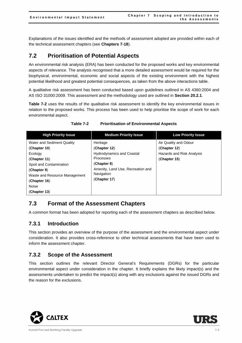
E n v i r o n m e n t a l I m p a c t S t a t e m e n t C h a p t e r 7 S c o p i n g a n d I n t r o d u c t i o n t o t h e A s s e s s m e n t s
Kurnell Port and Berthing Facility Upgrade 7-3
Explanations of the issues identified and the methods of assessment adopted are provided within each of the technical assessment chapters (see Chapters 7-18).
7.2 Prioritisation of Potential Aspects An environmental risk analysis (ERA) has been conducted for the proposed works and key environmental aspects of relevance. The analysis recognised that a more detailed assessment would be required for the biophysical, environmental, economic and social aspects of the existing environment with the highest potential likelihood and greatest potential consequences, as taken from the above interactions table.
A qualitative risk assessment has been conducted based upon guidelines outlined in AS 4360:2004 and AS ISO 31000:2009. This assessment and the methodology used are outlined in Section 20.2.1.
Table 7-2 uses the results of the qualitative risk assessment to identify the key environmental issues in relation to the proposed works. This process has been used to help prioritise the scope of work for each environmental aspect.
Table 7-2 Prioritisation of Environmental Aspects
High Priority Issue Medium Priority Issue Low Priority Issue
Water and Sediment Quality
(Chapter 10)
Ecology
(Chapter 11)
Spoil and Contamination
(Chapter 9)
Waste and Resource Management
(Chapter 16)
Noise
(Chapter 13)
Heritage
(Chapter 12)
Hydrodynamics and Coastal Processes
(Chapter 8)
Amenity, Land Use, Recreation and Navigation
(Chapter 17)
Air Quality and Odour
(Chapter 12)
Hazards and Risk Analysis
(Chapter 15)
7.3 Format of the Assessment Chapters A common format has been adopted for reporting each of the assessment chapters as described below.
7.3.1 Introduction This section provides an overview of the purpose of the assessment and the environmental aspect under consideration. It also provides cross-reference to other technical assessments that have been used to inform the assessment chapter.
7.3.2 Scope of the Assessment This section outlines the relevant Director General’s Requirements (DGRs) for the particular environmental aspect under consideration in the chapter. It briefly explains the likely impact(s) and the assessments undertaken to predict the impact(s) along with any exclusions against the issued DGRs and the reason for the exclusions.

C h a p t e r 7 S c o p i n g a n d I n t r o d u c t i o n t o t h e A s s e s s m e n t s E n v i r o n m e n t a l I m p a c t S t a t e m e n t
7-4 Kurnell Port and Berthing Facility Upgrade
7.3.3 Legislation and Planning Policy This section outlines legislation, guidance, policies and plans relevant to the environmental aspect forming the focus of the assessment reported in the chapter. A separate review of legislation and policy relevant to the proposed works as a whole is considered in Chapter 5, Legislation and Planning Policy.
7.3.4 Method of Assessment
Approach to Assessment
This section details the methodology adopted for the various assessments. It defines:
the study area adopted for each assessment;
the timescales adopted for each assessment;
the methods used to describe the existing environment of the study area (and how the environment may change over time);
the sensitive resources, receptors and values considered for each assessment (and any relationship between them);
any supporting modelling that has been undertaken;
specific impact assessment processes;
the method by which impacts (and impact magnitude) have been predicted and assessed; and
the method by which the significance of impact has been established.
Further specific detail on elements of the above is provided below.
Assessment Study Area
The extent of the study area for each assessment varies according to the environmental aspect being considered. Study areas have been determined in light of an initial review of the relationship of the proposed works to sensitive receptors (e.g. people, environmental features, fauna etc.) and the likelihood of consequential impacts. Occasionally, study areas are defined by legal or policy requirements.
For some aspects, the assessed study area is identified as being relatively localised to the proposed works. For others, it extends out to the surrounding waters of Botany Bay or considers wider communities and environmentally sensitive areas.
The extent of the study area for each aspect is described in each assessment chapter.
Assessment Timescales
The timescales adopted for each assessment also vary according to the environmental aspect being considered. For many environmental aspects the assessment is based on predicted changes occurring over the short duration of the works (such as changes to the noise environment during the proposed works). For others, the assessments consider the longer-term changes occurring following the works (such as changes to the ecology of the area or long-term changes to the hazard profile).

E n v i r o n m e n t a l I m p a c t S t a t e m e n t C h a p t e r 7 S c o p i n g a n d I n t r o d u c t i o n t o t h e A s s e s s m e n t s
Kurnell Port and Berthing Facility Upgrade 7-5
Resources, Receptors and Values
Environmental resources are defined as those aspects of the environment that support, and are essential to, natural or human systems. These include areas or elements of population, ecosystems, air and climatic factors, material assets, the marine environment, community and recreational facilities.
Environmental receptors are defined as people (occupiers of dwellings and users of the recreational areas of Botany Bay, places of employment and community facilities, and elements within the environment (flora and fauna)) that rely on resources. In terms of the assessments that predict the
potential likely impacts relating to heritage and ecology, receptors are termed values.
Evaluation of Magnitude of Impact
For each environmental assessment there is an explanation of the quantitative and qualitative criteria adopted to evaluate and determine the order of magnitude of beneficial and adverse impacts. These are either threshold limits (such as noise criteria) or ratings based on the order of impact (i.e. minor, moderate and major). The exception is Chapter 16, Waste and Resource Management where the assessment of waste and resource management impacts considers conformance to existing policy.
Assessment of Significance
The assessment of significance is set out for all assessment chapters, again with the exception of Chapter 16, Waste and Resource Management. This forms the basis against which the significance of an impact has been defined for the purpose of each specific assessment.
7.3.5 Existing Environment The section defines the existing environment that has the potential to be impacted as a result of the environmental aspect under consideration. It includes a description of the key components, characteristics and the status of the existing environment. It considers the prevailing conditions as appraised and surveyed to support this EIS. It also considers any changes to the existing environment over the period of time where the proposed works are to take place and for the continued operational life of the Kurnell port and berthing facility.
7.3.6 Impact Assessment This section identifies potential likely impacts and evaluates their significance in accordance with the criteria detailed in the Method of Assessment. The assessment considers impacts on the relevant resources, receptors and values considered in each of the environmental assessments.
Impacts comprise identifiable changes to the existing environment that would occur, or be likely to occur, as a consequence of undertaking the proposed works (e.g. alterations in water quality).
The connection between causative actions and environmental effects leads to the definition of an environmental impact as the difference between future conditions without the proposed works taking place, the predicted conditions during the implementation of the proposed works and the predicted conditions during the continued operational life of the Kurnell port and berthing facility. Environmental impacts are therefore measureable and can be assessed. Effects comprise the predicted consequences of the identified impacts (i.e. a loss of biota).
Impacts may be referred to either prior to (potential impact) or following mitigation (residual impact).

C h a p t e r 7 S c o p i n g a n d I n t r o d u c t i o n t o t h e A s s e s s m e n t s E n v i r o n m e n t a l I m p a c t S t a t e m e n t
7-6 Kurnell Port and Berthing Facility Upgrade
Each of the assessments evaluates and describes the nature of likely impacts predicted to result from proposed works. For all assessments, except Chapter 16, Waste and Resource Management, assessment defines impact ratings (thresholds) appropriate to the nature of the environmental aspect and in accordance with accepted terminology where standardised methodologies are used. As noted above, Chapter 16 simply assesses conformance with existing waste and resource management policy.
Impacts may be:
direct (e.g. a change in water and sediment quality); or
indirect (e.g. a coating with sediment of benthic ecological communities as a result of changes to the water quality).
They may be:
short-term/temporary (e.g. occurring during the proposed works);
medium-term (e.g. occurring during the proposed works however extending beyond the two-year works’ program); or
long-term/permanent (e.g. as a minimum occurring for the majority of the continued operational life of the Kurnell port and berthing facility).
They may be:
beneficial (e.g. provides a clear positive impact on the resources, receptors and/or values of the existing environment);
adverse (e.g. a detrimental or negative impact on the resources, receptors and/or values of the existing environment);
negligible (e.g. an environmental impact that is imperceptible or not significant to the resources, receptors and/or values of the existing environment); or
neutral (e.g. no perceived or predicted impact to the resources, receptors and/or values of the existing environment).
The prediction of impacts has been based on:
the known or likely presence of environmental resources/receptors/values;
the importance and/or sensitivity of the resources, receptors or values, as determined through their designated status or number, along with qualitative criteria such as rarity, status and condition;

E n v i r o n m e n t a l I m p a c t S t a t e m e n t C h a p t e r 7 S c o p i n g a n d I n t r o d u c t i o n t o t h e A s s e s s m e n t s
Kurnell Port and Berthing Facility Upgrade 7-7
the extent and magnitude of impact or change resulting from the proposed works, which can be defined in terms of its:
duration (whether short, medium or long-term);
nature (whether direct or indirect, reversible or irreversible);
whether the impact occurs in isolation, is cumulative or interactive;
performance against environmental quality standards; and
compatibility with environmental policies.
the ability of the resource/receptor to respond and adapt to change and thus its effectiveness to controlled change (i.e. mitigation).
7.3.7 Mitigation and Management Measures This section describes the mitigation and management measures that have been identified to reduce the significance of identified potential likely impacts.
The mitigation hierarchy has been adopted, which is one of avoidance wherever possible, followed by reduction, where avoidance cannot be achieved, or finally, compensation/offset where reduction cannot be achieved or would not achieve practicable or acceptable levels of mitigation.
This section also considers key residual impacts that would remain following the introduction of the mitigation and management measures. The key consideration is whether they are likely to result in a significant adverse residual effect on the environment, its resources, receptors or the values that rely on it.
The final section summarises the mitigation and management measures that Caltex would adopt on undertaking the proposed works. These measures include:
any specific design or environmental mitigation requirements, further assessments or clarifications required prior to starting the works;
any necessary additional licences and approvals required to be in place and approved prior to starting the works; and/or
any environmental management plans required to undertake the works.
In each case a summary is provided of the resultant mitigation and management measures proposed as a result of the assessed potential environment impacts.
7.3.8 Cumulative Effects Assessment A separate chapter (Chapter 18) has been prepared to consider cumulative effects. The chapter has considered the cumulative effects generated by the proposed works ‘alone’ and the cumulative effects that could potentially be generated ‘in combinatio’ with other likely future approved and committed development. Cumulative effect assessment (CEA) is a receptor based assessment, whereby in order to have a cumulative effect two projects or impacts must affect the same receptor. CEA focusses on impacts that have not been fully managed or mitigated (i.e. the residual impacts identified from the above assessments).
E n v i r o n m e n t a l I m p a c t S t a t e m e n t C h a p t e r 8 H y d r o d y n a m i c s a n d C o a s t a l P r o c e s s
Kurnell Port and Berthing Facility Upgrade 8-1
8 Hydrodynamics and Coastal Process
8.1 Introduction This chapter assesses the likely impact of the proposed works on the wave and water current (hydrodynamic) conditions of the area of Botany Bay close to the project site and any subsequent effect along the Bay’s shoreline. The assessment has relied on the results of detailed hydrodynamic modelling
by Cardno Ltd. This work is provided in Technical Appendix C.
Chapter 10, Water and Sediment Quality has relied on the same modelling to assess the impact of the proposed works on marine water and sediment quality.
8.2 Scope of the Assessment The Director General’s Requirements (DGRs) (see Technical Appendix A) requested that consideration be given to:
“hydrodynamic and coastal process changes to Botany Bay, including flushing, tidal flow and velocity, wave dynamics, storm surge impacts and effects on the shoreline of Botany Bay;
potential for the proposed works to alter the tidal range, water levels and saline intrusion to upstream water bodies and environments (including wetlands), stratification and anoxia;
scouring and erosion of the shoreline by natural forces and passing ships; and
impacts to the development resulting from climate change, including the consideration of the NSW sea level rise planning benchmarks.”
In addition, a number of associated issues have been raised by statutory agencies, which are relevant to this chapter. They include:
the need to determine any changes to wave energy and wave direction that may result from the final dredge footprint;
the need to consider all areas that could be impacted by altered hydrological and wave regimes in Botany Bay;
the need to consider if the hydrodynamic changes adversely affect the cultural heritage of Botany Bay; and
any impacts on the nearby sensitive aquatic habitats.
The modelled hydrodynamic changes have also been used to predict any changes to:
longshore sediment transport rates (the rate at which sediment moves along a beach);
impacts to Sydney (Kingsford Smith) Airport’s runways (which are formed on a reclaimed peninsula in the Bay);
effects on recreational boat user facilities in the area; and
any structural and design issues.

C h a p t e r 8 H y d r o d y n a m i c s a n d C o a s t a l P r o c e s s E n v i r o n m e n t a l I m p a c t S t a t e m e n t
8-2 Kurnell Port and Berthing Facility Upgrade
Consideration of how hydrodynamic changes potentially impact the heritage and ecology resources of Botany Bay have been considered in Chapters 11, Heritage and 12, Ecology. The issues of flushing
have been addressed in Chapter 10, Water and Sediment Quality.
8.3 Legislation and Planning Policy
Projected Changes in Climatological Forcing for Coastal Erosion in NSW1 2007
This Report considers the variables that are responsible for coastal erosion and how these may alter as a result of climate change. In particular, this Report considers changes to water current patterns, wind and wave climate, storm surges, and regional variations due to sea level rise. These changes have been accounted for in the infrastructure design for the proposed works.
With regard to storm surges, the Commonwealth Scientific and Industrial Research Organisation (CSIRO) (author of the above Report) has projected that the 100-year average recurrence interval (ARI) around Australian waters would be 0.7 m ± 0.2 m in 2070. This represents an increase of less than 8% in relation to the current storm surge height of 0.65 m ± 0.15 m.
CSIRO has also projected that changes to the maximum significant wave height during severe storms would change by between -15% to +32% by 2070, with a change in the frequency of occurrence of between -20% to +50%. CSIRO’s findings also report a negligible change to wave direction and periods by 2070.
NSW Government Sea Level Rise Policy Statement 2009
This Statement sets out the NSW Government’s objectives and commitments in relation to sea level rise adaptation. Importantly, it contains the Government’s sea level risk planning benchmarks.
The planning benchmarks support an adaptive risk-based approach to managing the impacts of sea level rise. The benchmarks are set as a projected increase above the 1900 mean sea levels of 0.4 m by 2050 and 0.9 m by 2100. These two benchmarks have been adopted in the design of the infrastructure for the port and berthing facility. This Statement has been given statutory effect through SEPP No 71 on Coastal Protection and through a Ministerial Direction to local councils under Section 117 of the Environmental Planning and Assessment (EP&A) Act 1979.
8.4 Method of Assessment
8.4.1 Introduction
The assessment has involved the following:
identification of the extent of Botany Bay and surrounding areas (including the associated shoreline area) that could be potentially impacted as a result of hydrodynamic and coastal process changes;
establishment of the existing environmental conditions relative to the physical processes that occur within Botany Bay, and relative to areas of the Bay that are sensitive to change (sensitive receptors);
1 CSIRO (2007) Projected Changes in Climatological Forcing for Coastal Erosion in NSW, A Project Undertaken for the NSW Department of Environment and Climate Change.
E n v i r o n m e n t a l I m p a c t S t a t e m e n t C h a p t e r 8 H y d r o d y n a m i c s a n d C o a s t a l P r o c e s s
Kurnell Port and Berthing Facility Upgrade 8-3
development of a number of ‘before and after’ modelling scenarios that account for changes to the physical processes resulting from the proposed works and their potential impact on identified sensitive receptors;
evaluation of the magnitude of impacts on sensitive receptors;
identification of mitigation in the form of modification to the dredging process and/or the implementation of management controls; and
a description of the predicted residual effects (if applicable).
8.4.2 Guidance and Standards
Responding to the Effects of Climate Change in Coastal and Ocean Engineering 20042
These Guidelines set out the key variables of climate change that may impact the design of marine structures. They include:
mean sea level rise, where an increase in water level may either require corrosion protection to be applied to a higher level on any piled structures or may affect the relative heights of superstructures;
wind climate, where any change may affect wind loads to any structures; and
wave climate, where a change to the offshore wave climate, as well as an increase in water level, has the potential to change the wave climate used for a design.
These Guidelines also provide a projected sea level rise for 2060, which ranges between 0.08 m and 0.4 m with a central estimate of 0.2 m. These factors have been considered in designing the proposed infrastructure and are discussed further below.
AS4997: Guidelines for the Design of Maritime Structures 2005
These Guidelines set out standards for the design of structures in a marine environment. They consider designs in the nearshore (accounting for climate change) and are therefore relevant to the proposed works. The also recommend allowances for a 50-year design life, which is to allow 0.2 m for sea level
rise.
8.4.3 Study Area and Timescales
The assessment and modelling has considered the whole of Botany Bay, the mouth of the Georges River and the area immediately offshore of Botany Bay (the Study Area) (see Figure 8-1). The assessment has considered both temporary and permanent impacts resulting from changes in the seabed profile and the
upgrade of the in-water structures associated with the port and berthing facility.
2 Prepared by the National Committee on Coastal and Ocean Engineering (NCCOE), Engineers Australia (2004)
C h a p t e r 8 H y d r o d y n a m i c s a n d C o a s t a l P r o c e s s E n v i r o n m e n t a l I m p a c t S t a t e m e n t
8-4 Kurnell Port and Berthing Facility Upgrade
8.4.4 Baseline
The identification and description of the existing environment has involved reviewing previous studies and assessments relating to Botany Bay and NSW (see Chapter 21, References). It has also involved building on previous modelling studies that Cardno has undertaken in Botany Bay (see Technical Appendix C). Data from these various sources has been used as background information for the hydrodynamic and coastal processes modelling for this assessment.
8.4.5 Modelling
Two models have been developed to assess the hydrodynamic and coastal process impacts of the proposed works.
The models have been setup and calibrated for previous investigations (Lawson and Treloar, 2003) and remain valid for the present study.
Hydrodynamic and Wave Effects (Current Modelling)
A 3D current model has been used to quantitatively model the hydrodynamic and wave-effect changes and subsequently the potential impacts on water and sediment quality resulting from the proposed works
(see Chapter 10, Water and Sediment Quality). The model has included data relating to wind, pressure, tide and wave forcing3, currents, stratification, rainfall/evaporation, sediment transport and water quality descriptions, as described in the existing environment section (see Chapter 3, Existing Environment).
The model has utilised a grid system, where predicted movement or change in the water is interpolated
between each cell of the grid. Close to the project site, a refined grid has been used to provide greater resolution to the predicted changes. For the inner part of Botany Bay and the outer coastal waters a coarser grid resolution has been used. The extent of the modelled area is shown in Figure 8-1.
Wave Dynamics and Coastal Processes
A second model has been developed to predict the potential changes to the wave dynamics and coastal processes as a result of the proposed works. It has accounted for existing development in the area and its influence on the hydrodynamics of Botany Bay.
Exclusion of the Rock Revetment and Sheet Piled Wall
The proposed works include a sub-tidal hard surfaced sheet piled wall faced with a rock revetment at the southern end of fixed berth #1. This structure is too small to be modelled in either of the models. The depth change from the seabed to the berth area is the same with this structure as it would be with a
dredged batter (which has been modelled) and the overall wave refraction effect would therefore be the same for both the battered and rock wall. Similarly, the results of the modelling (see Section 8.6.1) show that the proposed dredging would have no identifiable change on the depth-averaged currents speed and
direction. Similarly, this steep seabed feature would have little or no effect on these currents. Therefore, it can be concluded that this exclusion would not compromise the validity of the modelling approach.
3 How the effects of gravity (and the pull of the moon) affect both tides and waves.

E n v i r o n m e n t a l I m p a c t S t a t e m e n t C h a p t e r 8 H y d r o d y n a m i c s a n d C o a s t a l P r o c e s s
Kurnell Port and Berthing Facility Upgrade 8-5
The model has been used to prepare wave transfer coefficients4 for a range of tide heights for all waves directed offshore from north through east to south, and for a wave period that occurs from 3 to 11
seconds (as observed as being representative of the wave period in Botany Bay (see Technical Appendix C)). Again, the model has used a grid system with the resolution of the grid varying over the study area to reflect levels of detail required for the assessment.
8.4.6 Assessment of Significance
The results of the two models have shown where the predicted hydrodynamic and coastal process conditions differ from existing conditions within the study area. Where there are differences between the
existing environment and the model predictions, there could potentially be an impact. To understand the significance of this impact, the magnitude, scale and duration of hydrological changes under the proposed works have been compared to natural changes in the area.
4 The variables that cause the energy in waves to transfer from one area to another area.
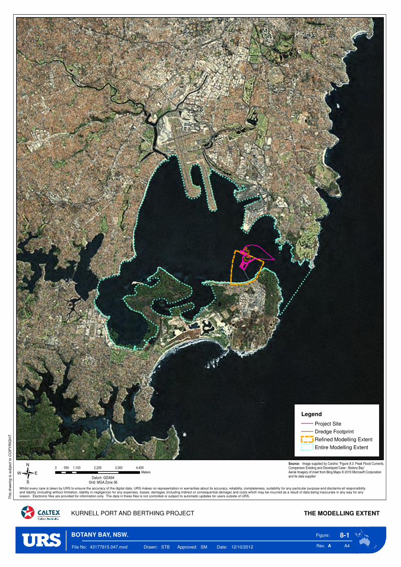
Figure:
Rev. A4
8-1
KURNELL PORT AND BERTHING PROJECT THE MODELLING EXTENT
This
dra
win
g is s
ub
ject
to C
OP
YR
IGH
T.
/
A
0 1,100 2,200 3,300 4,400550
Meters
Datum: GDA94Grid: MGA Zone 56
File No: 43177815.047.mxd Drawn: STB Approved: SM Date: 12/10/2012
Whilst every care is taken by URS to ensure the accuracy of the digital data, URS makes no representation or warranties about its accuracy, reliability, completeness, suitability for any particular purpose and disclaims all responsibilityand liability (including without limitation, liability in negligence) for any expenses, losses, damages (including indirect or consequential damage) and costs which may be incurred as a result of data being inaccurate in any way for any reason. Electronic files are provided for information only. The data in these files is not controlled or subject to automatic updates for users outside of URS.
Source: Image supplied by Cardno: 'Figure 8.3: Peak Flood Currents, Comparison Existing and Developed Case - Botany Bay'
Aerial Imagery of inset from Bing Maps © 2010 Microsoft Corporationand its data supplier
BOTANY BAY, NSW.
Legend
Project Site
Dredge Footprint
Refined Modelling Extent
Entire Modelling Extent

E n v i r o n m e n t a l I m p a c t S t a t e m e n t C h a p t e r 8 H y d r o d y n a m i c s a n d C o a s t a l P r o c e s s
Kurnell Port and Berthing Facility Upgrade 8-7
8.5 Existing Environment
8.5.1 Overview of Botany Bay The entrance to Botany Bay is approximately 1.1 km wide and comprises a dredged navigation channel that is approximately 20 m below chart datum (CD). It provides access to Port Botany and the Kurnell port and berthing facility. Outside the Bay the seabed falls away rapidly to over 80 m below CD approximately
1 km offshore. The Bay entrance is subject to ocean swell offshore from the east. Despite its exposure to waves and a small tidal range, it is the tidal processes within the Bay rather than ocean swell waves that predominantly influence water circulation and flushing within its boundaries5.
The seabed depth and profile within the Bay has been heavily modified to accommodate the existing
Kurnell port and berthing facility (1953), as well as to construct the airport runways (1964-1971), to construct and expand Port Botany (1978, 1982 and 2006-2013), and to create the main shipping channel (various dates). Despite this, the mean water depth is recorded at approximately 5 m below CD, making it
a very shallow environment. This causes shoaling6 westward from the dredged shipping channel at the entrance.
The foreshore areas of the Bay include rocky headlands, sandy beaches (comprising marine derived sands) and sheltered embayments. These areas are typical of the study area close to the project site.
Local to the project site is the southern part of Kamay Botany Bay National Park (comprising a rocky
headland east of the project site), Silver Beach (comprising a sandy, shallow-profile beach, located immediately south of the project site), and the sheltered regions of Quibray and Woolooware Bays located to the west. The other principal shoreline features in the study area include Bonna Point (at
Kurnell), Towra Beach to the west (associated with the sensitive ecological sites that form the Towra Point Nature and Aquatic Reserves), and Lady Robinsons Beach (which is located further west fronting Ramsgate, Monterey and Brighton-le-Sands).
The Georges River Basin provides the main riverine input to the Bay. It discharges via the Georges River
into the southwest corner of the Bay at Towra Point. The smaller Cooks River discharges to the north-western corner of the Bay south of Sydney Airport. The fresh water flow from both rivers is normally small compared to the tidal flow.
8.5.2 Coastal Processes
The key coastal processes in the Bay relevant to this assessment include the erosion, transportation and
accumulation of sediment. The beaches in the Bay are shaped through the process of sediment transport and deposition via waves and currents.
Sediment may be transported as a bed load or suspended load. Bed load is the process by which particles are transported along the seabed. The larger particles move by rolling, sliding or ‘saltating’ in a
series of hops. The finer particles are able to remain suspended in the water body, and are transported via turbulent mixing, which counteracts the speed of the falling particles as they disperse upward from the
5 Cardno, Taylor, Treloar (2007). 6 The resultant effect of where waves enter shallower water resulting in an increase in effective wave height. Waves tend to shoal prior to breaking at the shoreline.

C h a p t e r 8 H y d r o d y n a m i c s a n d C o a s t a l P r o c e s s E n v i r o n m e n t a l I m p a c t S t a t e m e n t
8-8 Kurnell Port and Berthing Facility Upgrade
seabed. The difference in the two transport methods is important to this assessment as both would affect how the dredged sediments would disperse within the Bay. This is discussed in detail in Chapter 10, Water and Sediment Quality.
Sediment is either transported onshore, offshore or along the shoreline (longshore). Where waves break obliquely to the shoreline this causes longshore transport (or longshore drift). Offshore transport normally occurs during a storm event, with longer term onshore transport following such storm events.
The other main dynamic process in the Bay is the addition of fine sediment that is washed into the Bay
from the river catchments of the Georges and Cooks River. This sediment tends to settle in the more sheltered regions of the Bay or is washed out to sea.
8.5.3 Shoreline Features and Beach Stability
The stability of sandy beaches on the western and southern shoreline of the Bay is influenced by ocean swell waves that penetrate the entrance to the Bay. The dredging at the entrance to the Bay has
substantially changed the wave climate and consequently the areas where sediments are eroded and deposited inside the Bay. To a lesser extent, locally generated wind-waves (waves generated as a result of wind passing over the sea surface) and currents have also influenced sediment transport and beach
stability of the shoreline.
Both natural and man-made changes since the time of European settlement have affected sediment transport and coastal stability through changes to the wave climate. This has resulted in the need to protect some of the major beaches around the Bay. These beaches have been protected in the following
ways.
Silver Beach has been protected from storm erosion by building groynes. Generally, these groynes have functioned satisfactorily for nearly forty years. Small changes in wave height and direction on Silver Beach have had no effect on the shoreline.
Towra Beach remains a dynamic unprotected area, and therefore susceptible to hydrodynamic changes. Long-term changes are continuing as a result of natural processes, the effects of the previous widespread dredging that has taken place across the Bay, and the development and modification of parts of the shoreline. Towra Beach has been shown to be receding at about 1 to 2 m per year as a result5. Changes on the beach are irregular and are caused mainly by storm events accompanied by high tides.
Lady Robinsons Beach incudes groynes along the southern beach area up to just south of President Avenue. The northern beach area has been subject to beach renourishment as shoreline recession has occurred at this location. The sediment transport and erosion processes along the beach are caused by swell and have been heavily influenced due to the construction of the airport runways. Longshore transport moves southward and northward along the beach, with the null point located near Pasadena Street in Monterey. The inclusion of the groynes and the renourishment program has stabilised the beach over the past few years.
The Georges River tidal flow has incised a wide, shallow, entrance waterway to the Bay that has formed steep sides in some areas, whilst creating the Taylor Bar Spit at Dolls Point.

E n v i r o n m e n t a l I m p a c t S t a t e m e n t C h a p t e r 8 H y d r o d y n a m i c s a n d C o a s t a l P r o c e s s
Kurnell Port and Berthing Facility Upgrade 8-9
8.5.4 Climate Change The regional coastal projections of climate change consider sea level rise, wind, the frequency of extreme
events and the adoption of climate change scenarios. These metrics are discussed further in Technical Appendix C.
Sea Level Rise: Estimated recorded sea level rise from 1950-2000 in Australia is 1.3 (± 0.5) mm per year, which is less than the global average. Planning benchmarks have been set in NSW for future estimated sea level rise in the context of these predictions (see Section 8.3).
Wind: The findings of a 2004 study7 predicted a greater number of extreme wind events to occur in winter months in southern NSW as a result of climate change.
Frequency of Extreme Events: Whilst there is an appreciation that the frequency of extreme events is increasing globally as a result of climate change there is no agreement on those effects in NSW or Australia, with various studies contradicting each other.
For the purpose of this EIS it has been assumed that the tidal range that currently exists (relative to the rising mean sea level), wind prominence, and storm intensity and frequency would remain unchanged in the future. Backed by the uncertainty in the various climate change projections for these features, it has been considered appropriate to adopt conditions based on current climatology and historical records. Any
implications for an alternative position would be very minor over the life of the proposed works and the design life of the upgraded port and berthing facility.
8.5.5 Hydrological Assessment Characteristics
The hydrodynamic modelling and assessment has used the following physical characteristics data for Botany Bay:
currents and circulation;
wind and wave conditions;
swell waves, wave height and wave direction; and
tidal range.
The principal features of these characteristics are summarised below and detailed in Technical Appendix C. The modelling has not included wind because moderate winds have little effect on currents in the majority of Botany Bay (see Technical Appendix C).
Currents and Circulation: The currents in Botany Bay are caused by a range of factors including tides, winds, river discharges, coastal trapped waves, wave processes near the shore, density flows and other Tasman Sea processes. The currents in the Bay are predominantly tide, wind and river generated, with velocities remaining generally low (usually less than 2 cms-1).
7 Hennessy et al., 2004a and , Hennessy et al., 2004b
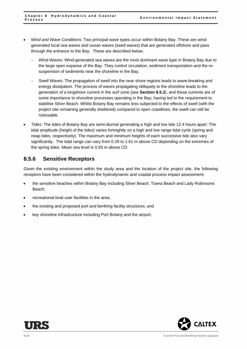
C h a p t e r 8 H y d r o d y n a m i c s a n d C o a s t a l P r o c e s s E n v i r o n m e n t a l I m p a c t S t a t e m e n t
8-10 Kurnell Port and Berthing Facility Upgrade
Wind and Wave Conditions: Two principal wave types occur within Botany Bay. These are wind-generated local sea waves and ocean waves (swell waves) that are generated offshore and pass through the entrance to the Bay. These are described below.
Wind-Waves: Wind-generated sea waves are the most dominant wave type in Botany Bay due to the large open expanse of the Bay. They control circulation, sediment transportation and the re-suspension of sediments near the shoreline in the Bay.
Swell Waves: The propagation of swell into the near shore regions leads to wave-breaking and energy dissipation. The process of waves propagating obliquely to the shoreline leads to the generation of a longshore current in the surf zone (see Section 8.5.2), and these currents are of some importance to shoreline processes operating in the Bay; having led to the requirement to stabilise Silver Beach. Whilst Botany Bay remains less subjected to the effects of swell (with the project site remaining generally sheltered) compared to open coastlines, the swell can still be noticeable.
Tides: The tides of Botany Bay are semi-diurnal generating a high and low tide 12.4 hours apart. The tidal amplitude (height of the tides) varies fortnightly on a high and low range tidal cycle (spring and neap tides, respectively). The maximum and minimum heights of each successive tide also vary significantly. The tidal range can vary from 0.29 to 1.61 m above CD depending on the extremes of the spring tides. Mean sea level is 0.93 m above CD.
8.5.6 Sensitive Receptors
Given the existing environment within the study area and the location of the project site, the following receptors have been considered within the hydrodynamic and coastal process impact assessment:
the sensitive beaches within Botany Bay including Silver Beach, Towra Beach and Lady Robinsons Beach;
recreational boat user facilities in the area;
the existing and proposed port and berthing facility structures; and
key shoreline infrastructure including Port Botany and the airport.

E n v i r o n m e n t a l I m p a c t S t a t e m e n t C h a p t e r 8 H y d r o d y n a m i c s a n d C o a s t a l P r o c e s s
Kurnell Port and Berthing Facility Upgrade 8-11
8.6 Impact Assessment
8.6.1 Changes in Current Speed The 3D model described in Section 8.4.5 has been used to assess the changes in water current speed and direction that would result from the proposed dredging and reuse of sediments in Botany Bay (see Section 4.4.9). Modelling simulations have been run for a period of spring and neap tides to compare the existing conditions against the proposed conditions following the dredging. The results of each simulation have been presented as a range of vector plots, showing the size and direction of the peak flood and ebb currents. These plots are shown on Figures 8-2 and 8-38. The size of the arrow reflects the speed of the existing and predicted currents.
By comparing the modelling outcomes (as illustrated in the two Figures) it can be concluded that the proposed dredging would cause negligible changes to the tidal currents within Botany Bay.
The model has not assessed the effects of installing the piles required to support the berthing infrastructure associated with fixed berth #1 (described in Chapter 4, Proposed Works Description) on
localised currents. Some minor changes to the currents may occur locally around the project site as a result of installing proposed equipment. However such changes would be too small to result in any significant scour and or erosion (see Section 8.6.7). This is equally true of the anchoring spuds that
would be used by the backhoe dredger.
8 The predicted changes are so small that there is no identifiable (negligible) change in the pre and post conditions (specifically, the post-dredging vector arrows (red) completely overlay the pre-dredging vector arrows (green) at the scale presented on the two Figures.
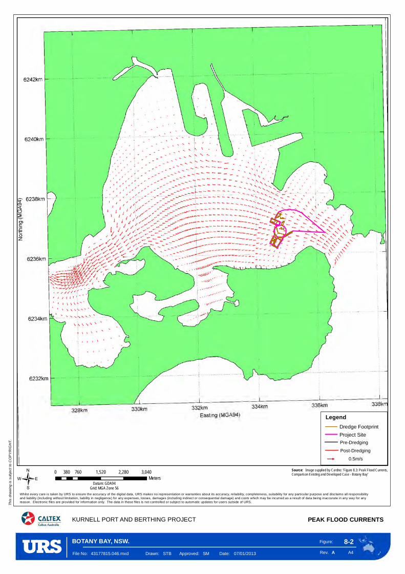
Figure:
Rev. A4
8-2
KURNELL PORT AND BERTHING PROJECT PEAK FLOOD CURRENTS
This
drawi
ng is
subje
ct to
COPY
RIGH
T.
/
A
0 760 1,520 2,280 3,040380Meters
Datum: GDA94Grid: MGA Zone 56
File No: 43177815.046.mxd Drawn: STB Approved: SM Date: 07/01/2013
Whilst every care is taken by URS to ensure the accuracy of the digital data, URS makes no representation or warranties about its accuracy, reliability, completeness, suitability for any particular purpose and disclaims all responsibilityand liability (including without limitation, liability in negligence) for any expenses, losses, damages (including indirect or consequential damage) and costs which may be incurred as a result of data being inaccurate in any way for any reason. Electronic files are provided for information only. The data in these files is not controlled or subject to automatic updates for users outside of URS.
Source: Image supplied by Cardno: 'Figure 8.3: Peak Flood Currents, Comparison Existing and Developed Case - Botany Bay'
BOTANY BAY, NSW.
LegendDredge Footprint
Project Site
0.5m/s
Pre-Dredging
Post-Dredging
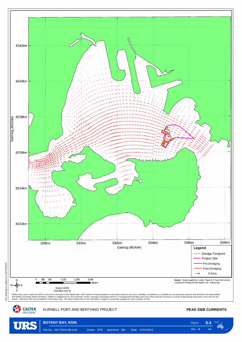
Figure:
Rev. A4
8-3
KURNELL PORT AND BERTHING PROJECT PEAK EBB CURRENTS
This
drawi
ng is
subje
ct to
COPY
RIGH
T.
/
A
0 760 1,520 2,280 3,040380Meters
Datum: GDA94Grid: MGA Zone 56
File No: 43177815.048.mxd Drawn: STB Approved: SM Date: 07/01/2013
Whilst every care is taken by URS to ensure the accuracy of the digital data, URS makes no representation or warranties about its accuracy, reliability, completeness, suitability for any particular purpose and disclaims all responsibilityand liability (including without limitation, liability in negligence) for any expenses, losses, damages (including indirect or consequential damage) and costs which may be incurred as a result of data being inaccurate in any way for any reason. Electronic files are provided for information only. The data in these files is not controlled or subject to automatic updates for users outside of URS.
Source: Image supplied by Cardno: 'Figure 8.3: Peak Ebb Currents, Comparison Existing and Developed Case - Botany Bay'
BOTANY BAY, NSW.
0.5m/s
Pre-Dredging
Post-Dredging
LegendDredge Footprint
Project Site
C h a p t e r 8 H y d r o d y n a m i c s a n d C o a s t a l P r o c e s s E n v i r o n m e n t a l I m p a c t S t a t e m e n t
8-14 Kurnell Port and Berthing Facility Upgrade
8.6.2 Wave Dynamics and Coastal Processes
Wind-Wave Conditions
The modelling described in Section 8.4.5 has confirmed that no change would occur to local wind-wave
conditions as a result of the proposed works. This is because fetches (which have the greatest influence on wind-waves) would remain unchanged.
Wave Dynamics and Coastal Processes
The modelling has also considered swell wave propagation into Botany Bay based on a worst case conservative scenario. A matrix of wave coefficients and inshore wave directions has been used to provide information on changes in wave height and direction at various locations around the Bay. These
locations (shown in Figure 8-4) have been taken at a depth of approximately 1 m above CD to represent changes to the shoreline around the Bay.
The wave coefficient and inshore wave directions were then combined with swell wave data to provide a corresponding time-series to show how the combined wave parameters would potentially affect the
shoreline in terms of changes to wave height and wave direction. The model results have suggested that a minor change to these parameters would occur only on Silver Beach and within the groyne field, where changes in (significant) wave heights would be +/-0.05%9 compared against existing conditions. The
results are illustrated in Figures 8-5, 8-6 and 8-7, which provide three different time series and wave direction plots representative of the conditions encountered in Botany Bay.
Estimates were made of the total sediment transport potential at each output location shown on Figure 8-4, when combined with the physical characteristics of the shoreline and the nature of the
sediment. The model results suggest that there would be minor changes (ranging from -0.4% to +0.4%) to the significant wave height along Silver Beach. There would be no changes at the runways, in Port Botany, or at the main recreational fishing sites to the north (see Chapter 17, Amenity, Land Use, Recreation and Navigation).
The most significant issue would be changes in wave direction as this has the potential to affect longshore transport process and therefore the stability of Silver and Towra Beaches. The modelling has confirmed that there would be no changes in wave direction west of Output Location 30 (shown on Figure 8-4, the entrance to Quibray Bay). Changes to the east of this point would be minor (less than 0.1o of direction) and would be contained within the Silver Beach groyne field (see Figures 8-5, 8-6 and 8-7). The changes shown on Towra Beach would be less than 0.1o and would have negligible impact on that
beach’s transport processes.
The modelling comparison generally suggests that the wave parameters post-dredging would be very similar to those for the existing environment. Therefore, it is unlikely that the proposed works would result in a significant change in the existing erosion/deposition rates or the coastal processes along the Botany
Bay shoreline.
9 Measured as a change in significant wave height Hs (%).

Figure:
Rev. A4
8-4
WAVE PARAMETER OUTPUT LOCATIONS
Th
is d
raw
ing
is s
ub
ject
to C
OP
YR
IGH
T.
/
A
0 1 20.5
Kilometres
Datum: GDA94Grid: MGA Zone 56
File No: 43177815.049.mxd Drawn: STB Approved: SM Date: 13/12/2012
Whilst every care is taken by URS to ensure the accuracy of the digital data, URS makes no representation or warranties about its accuracy, reliability, completeness, suitability for any particular purpose and disclaims all responsibility and liability (including without limitation, liability in negligence) for any expenses,losses, damages (including indirect or consequential damage) and costs which may be incurred as a result of data being inaccurate in any way for any reason. Electronic files are provided for information only. The data in these files is not controlled or subject to automatic updates for users outside of URS.
KURNELL PORT AND BERTHING PROJECT
Source: Image supplied by Cardno: 'Figure 8.5: Wave Parameter Output Locations, Comparison Existing and Developed Case - Botany Bay'
BOTANY BAY, NSW.
Legend
Dredge Footprint
Project Site

Figure:
Rev. A4
8-5
SIGNIFICANT WAVE HEIGHT CHANGES (%)OFFSHORE DIRECTION ESE
Th
is d
raw
ing
is s
ub
ject
to C
OP
YR
IGH
T.
/
A
0 0.75 1.5 2.25 30.375
KilometresDatum: GDA94
Grid: MGA Zone 56
File No: 43177815.050.mxd Drawn: STB Approved: SM Date: 12/10/2012
Whilst every care is taken by URS to ensure the accuracy of the digital data, URS makes no representation or warranties about its accuracy, reliability, completeness, suitability for any particular purpose and disclaims all responsibility and liability (including without limitation, liability in negligence) for any expenses,losses, damages (including indirect or consequential damage) and costs which may be incurred as a result of data being inaccurate in any way for any reason. Electronic files are provided for information only. The data in these files is not controlled or subject to automatic updates for users outside of URS.
KURNELL PORT AND BERTHING PROJECT BOTANY BAY
Source: Image supplied by Cardno: 'Figure 8.6 (9.2): Hs Changes (%)Output Locations, mparison Existing and Developed Case - Botany Bay'
BOTANY BAY, NSW.
Legend
Project Site
Dredge Footprint

Figure:
Rev. A4
8-6
SIGNIFICANT WAVE HEIGHT CHANGES (%)OFFSHORE DIRECTION SE
Th
is d
raw
ing
is s
ub
ject
to C
OP
YR
IGH
T.
/
A
0 0.75 1.5 2.25 30.375
KilometresDatum: GDA94
Grid: MGA Zone 56
File No: 43177815.051.mxd Drawn: STB Approved: SM Date: 12/10/2012
Whilst every care is taken by URS to ensure the accuracy of the digital data, URS makes no representation or warranties about its accuracy, reliability, completeness, suitability for any particular purpose and disclaims all responsibility and liability (including without limitation, liability in negligence) for any expenses,losses, damages (including indirect or consequential damage) and costs which may be incurred as a result of data being inaccurate in any way for any reason. Electronic files are provided for information only. The data in these files is not controlled or subject to automatic updates for users outside of URS.
KURNELL PORT AND BERTHING PROJECT BOTANY BAY
Source: Image supplied by Cardno: 'Figure 8.6 (9.3): Hs ChangesComparison Existing and Developed Case - Botany Bay'
BOTANY BAY, NSW.
Legend
Project Site
Dredge Footprint

Figure:
Rev. A4
8-7
HS CHANGES (%)
Th
is d
raw
ing
is s
ub
ject
to C
OP
YR
IGH
T.
/
A
0 0.75 1.5 2.25 30.375
KilometresDatum: GDA94
Grid: MGA Zone 56
File No: 43177815.052.mxd Drawn: STB Approved: SM Date: 04/10/2012
Whilst every care is taken by URS to ensure the accuracy of the digital data, URS makes no representation or warranties about its accuracy, reliability, completeness, suitability for any particular purpose and disclaims all responsibility and liability (including without limitation, liability in negligence) for any expenses,losses, damages (including indirect or consequential damage) and costs which may be incurred as a result of data being inaccurate in any way for any reason. Electronic files are provided for information only. The data in these files is not controlled or subject to automatic updates for users outside of URS.
KURNELL PORT AND BERTHING PROJECT
Source: Image supplied by Cardno: 'Figure 8.8 (9.4): Hs ChangesComparison Existing and Developed Case - Botany Bay'
BOTANY BAY, NSW.
Legend
Dredge Footprint
Project Site

E n v i r o n m e n t a l I m p a c t S t a t e m e n t C h a p t e r 8 H y d r o d y n a m i c s a n d C o a s t a l P r o c e s s
Kurnell Port and Berthing Facility Upgrade 8-19
8.6.4 Comparative Basis of the Models The modelling has been undertaken on a comparative basis. In other words, the model has focused on
the differences between hydrodynamic and wave conditions for existing and post-development cases. Therefore, any discrepancy in model performance would be consistent for both cases and would not influence the overall assessment of potential changes that may arise due to the proposed works.
8.6.5 Flushing Contaminant tracer modelling undertaken to support this EIS (see Chapter 10, Water and Sediment Quality) has confirmed that flushing is not a concern within this part of Botany Bay. Tidal currents would transport any sediment along the coast readily and the proposed works would not change the structure and speeds of existing currents within the Bay (see Section 8.6.1).
The proposed works would not change the tidal prism (the volume of water in the Bay between mean high tide and mean low tide) near the site or in the Bay because all dredging work would take place below low tide level and hence flushing would remain as it is now. In fact, being deeper, there would be a negligible improvement in flushing due to the lower seabed friction resulting in a negligible increase in the tidal prism.
8.6.6 Anoxia Anoxic waters are areas that are depleted of dissolved oxygen. The condition is found in areas that generally have restricted water exchange. The shallow depth and hydrodynamics of Botany Bay provide sufficient mixing to ensure there is a good level of dissolved oxygen (DO) throughout the water column, which prevents anoxia occurring. This has been confirmed through the monitoring undertaken by the Sydney Metropolitan Catchment Management Authority (CMA), which shows DO to be above 250% saturation, which is high10.
The proposed works have the potential to create anoxic conditions through two mechanisms. The first would be the development of possible anoxic conditions due to the creation of areas of stagnant unmixed water, and the second would be the creation of anoxic conditions through the disturbance of the peat and other acid sulphate soils (ASS) that are prevalent across the Bay (see Section 9.5.2). Anoxia can occur if the rate of oxidation by the ASS is greater than the supply of DO. Based on our assessment, it can be concluded that the proposed works are unlikely to cause anoxia by either means for the reasons discussed below.
Creation of Stagnant Water
The hydrodynamics of Botany Bay have a significant influence on water quality. Anoxic conditions can develop within depressions on the seabed where currents are not sufficiently strong to mix the near seabed water, and where oxygen is consumed by organisms and not replenished by the hydrodynamic processes. Currents around the area of the proposed works are much stronger than those within other areas of the Bay where anoxia is a concern, such as Port Botany. In these areas the seabed is much deeper, preventing the oxygenation of the water. This is especially true of the recently expanded shipping area and residual dredged borrow area of Port Botany. Moreover, the proposed dredging profile formed
10 http://www2.ecowise.com.au/reports.aspx

C h a p t e r 8 H y d r o d y n a m i c s a n d C o a s t a l P r o c e s s E n v i r o n m e n t a l I m p a c t S t a t e m e n t
8-20 Kurnell Port and Berthing Facility Upgrade
on the seabed is open sided and unlikely to cause stagnant areas. Constant shipping movements and propeller caused currents (which currently influence the existing environment) are also likely to assist in the exchange of sea water.
Disturbance of ASS and Peat
It is accepted that working the seabed to remove ASS and peat would generate some localised oxidation due to the anoxic nature under which these sediments have formed, backed by their low pH (acid nature), which can also reduce DO. However, the buffering capacity of seawater (i.e. its ability to neutralise acid), continual flushing (see above) and the volume of water into which any disturbed sediments would dilute and disperse suggest that any acid generated would be quickly neutralised. This would result in there being very little reduction in DO occurring in the water column. This is supported by the use of a closed backhoe, which has a low impact on the seabed and minimises spill rates on lifting the material. The overflow process could also return a quantum of acid-generating sediment to the water column; however the dilution and dispersion acting on the sediment in context of the volumes of sediment generated would not lead to any significant anoxia with the sediments being rapidly neutralised.
8.6.7 Scour and Erosion A further issue of the proposed works would be the potential for scour effects associated with the continued use of the berths (resulting from propeller wash), the installation of new structures, and any effects due to changes in the hydrodynamics of the area.
For the existing port and berthing facility the only evidence of scour is the presence of two small scour holes in the fixed berths resulting from the berthing of ships at these locations for the past 55 years. The extent of scour is limited to within the berth and has not resulted in a requirement to provide scour protection to any of the existing subsea structures associated with the launch jetty or Wharf.
The reconfiguration of the berthing arrangements and introduction of larger ships with greater propulsion power and propeller diameter within fixed berth #1 may have the potential to cause additional scour to the seabed and around the structures.
The influence of any resulting currents may extend further landward towards existing seabed areas than is currently the case.
The potential for scour around the existing and proposed subsea structures as a result of the predicted changes in current speed and direction due to the dredging have been assessed in developing the concept design. The results of this assessment have confirmed that any scour effects would be highly localised and minimal, consistent with the scouring that has occurred around the existing Wharf piles, which over the past 55-years of operation has not warranted any protection measures.
As a result of the reconfiguration of fixed berth #1, scour protection would be included at the top and toe of the sheet piled wall for the rock revetment. This is the area where the most change would be expected due to the increased dredge depth and the introduction of larger propeller wash. The purpose of the sheet piled wall and rock revetment would be to prevent scour to the existing Wharf piles located south of the berth. With these measures in place any minor scour effects would be contained within fixed berth #1, the only residual impact being the likely creation of a scour hole in front of the rock revetment, consistent with the small scour holes currently located in the fixed berths.

E n v i r o n m e n t a l I m p a c t S t a t e m e n t C h a p t e r 8 H y d r o d y n a m i c s a n d C o a s t a l P r o c e s s
Kurnell Port and Berthing Facility Upgrade 8-21
No scour protection would be proposed at fixed berth #2 as the size of ship berthing at this location would not change, and while the design depth would change along with the construction of batter slopes, it would be less than fixed berth #1. Whilst there is an existing scour hole in fixed berth #2 the concept design has confirmed that any changes to this hole would be negligible.
Within the port and berthing facility there is an imposed 4 knot speed limit that would be enforced for all ships associated with the proposed works. This would prevent any wash effects or coastal related scour and erosion impacts. Post the works the anticipated reduction in shipping (see Section 4.6.4) would ease pressure on the shipping channel limiting any cumulative scour effects due to passing ships.
8.6.8 Storm Surge, Tidal Range and Saline Intrusion
Both the assessment and modelling results (see Section 8.6), have indicated negligible changes to:
storm surge impacts;
tidal range/water levels; and
saline intrusions.
This is due to the proposed works causing minor changes to the dynamics and ‘energy’ of the environment to generate such impacts.
8.6.9 Climate Change The following impacts to the proposed works have been considered as a result of climate change.
Sea Level Rise and Storm Surge
The deck levels of the various maritime structures at the port and berthing facility vary from 3.8 m above CD to 6.2 m above CD. For a tidal range of approximately 1.6 m (see Table 8-1) and a storm surge of around 0.7 m (see Section 8.3), there is ample freeboard on the structures to accommodate the various
projected sea level rises over the design life of the facility (see Section 8.3).
Consequently, there is no requirement to increase the deck levels or working heights of any platforms forming part of the port and berthing facility, or change the mooring arrangements, loading arms, structural features or fire services beyond the current design to account for sea level rise.
However, the projected increase in sea level has required that corrosion protection be provided higher up
the existing and proposed piles. This has been included within the coating and corrosion specifications for the piles.
Wind Climate
The port and berthing facility has operational limits on when it is safe to berth, load and unload. Above a certain wind speed ships are not permitted to enter the berths. These limits would remain in place following the completion of the proposed works.
Any increase in wind strength would not affect the actual design of the facilities as the wind strength
impact on the exposed structures is not a critical design factor.
Wave Climate
C h a p t e r 8 H y d r o d y n a m i c s a n d C o a s t a l P r o c e s s E n v i r o n m e n t a l I m p a c t S t a t e m e n t
8-22 Kurnell Port and Berthing Facility Upgrade
The potential changes in wave conditions identified through this assessment (see Section 8.6.2) are such that they would have a negligible impact on water level and wave transformation patterns. Consequently,
they do not require consideration in terms of the loading conditions placed on the infrastructure forming upgraded port and berthing facility.
8.7 Mitigation
8.7.1 Discussion The results of the modelling demonstrate that the effects of the proposed dredging works on the
hydrodynamics and coastal processes within Botany Bay would be, at most, minor and would not require the development of specific mitigation measures. As the model has been calibrated there would be no requirement to validate the results either through modelling refinement or monitoring.
Notwithstanding this, it is proposed that a range of working practices and design features would be
undertaken to support the proposed works. These include:
limiting the use of overflow dredging within the fixed berths so as to limit sediment discharge close to shore;
undertaking further assessments during the detailed design to ensure there would be no potential for scour and erosion issues around the berths, jetty and Wharf; and
ensuring the post dredged seabed profile is consistent with the existing profile so as to minimise the potential increase in swell waves onshore.
In addition, the proposed sediment and water quality monitoring program (see Section 10.7.2) would provide live monitoring data reporting any unpredicted suspended sediment loading that would occur as a
result of the proposed works. If substantial or significant, this would inform any decision to implement further assessment or controls beyond those included as mitigation in this EIS to ensure there would be no follow-on effects to the southern shoreline beaches in Botany Bay.
8.7.2 Summary
Table 8-1 outlines the mitigation and management measures that would be put in place to avoid or
minimise the likely hydrodynamic and coastal process impacts resulting from the proposed works.
Table 8-1 Hydrodynamic and Coastal Process Mitigation and Management Measures
Mitigation and Management Measures Implementation
Design Implementation Operation
Overflow dredging would not be permitted within the fixed berths during the dredging works.
The detailed design would include measures to minimise the potential for localised erosion or scour around the berths and Wharf structure. The design would be in accordance with the AS4997: Guidelines for the Design of Maritime Structures.
E n v i r o n m e n t a l I m p a c t S t a t e m e n t C h a p t e r 9 S p o i l a n d C o n t a m i n a t i o n
Kurnell Port and Berthing Facility Upgrade 9-1
9 Spoil and Contamination
9.1 Introduction
The following chapter assesses the characteristics of the dredged sediment along with disposal and
reuse options for that material. The assessment has been based on analysis of the sediments undertaken
by Worley Parsons (see Technical Appendices D1 and D2).
The likely impact of the proposed works on the water and sediment quality of Botany Bay resulting from
the disturbance and mobilisation of sediments is discussed in Chapter 10, Water and Sediment Quality.
The likely impact from odour caused by exposure of sediment to air following dredging is discussed in
Chapter 14, Air Quality and Odour.
9.2 Scope of the Assessment
The Director General’s Requirements (DGRs) (see Technical Appendix A) requested that consideration
be given to:
• “an assessment of the volume and type of sediment materials to be dredged, including the potential
for the dredging of Acid Sulfate Soils, taking into account the Acid Sulfate Soil Manual
(ASSMAC,1998);
• potential for contaminated sediments and groundwater (including Tributyltin), their disturbance during
excavation and dredging works, and identification of potential risk to human health, aquaculture
activities or the environment;
• sampling and characterisation of the distribution of contamination, taking into account the Sediment
Quality Guidelines (CSIRO Handbook, 2000);
• spoil disposal and reuse options, including identification and description of potential disposal locations
and associated impacts; and
• if contamination is identified and remediation of material is necessary, preparation of a Remediation
Action Plan (RAP) or other appropriate materials handling procedures taking into account the
Contaminated Land Management Act 1997.”
9.3 Legislation and Planning Policy
Commonwealth Environmental Protection (Sea Dumping) Act 1981
This Act regulates the loading and disposal of waste materials at sea. This includes the disposal of
dredged sediment. A sea dumping permit (SDP) is required from the Commonwealth Department of
Sustainability, Environment, Water, Population and Communities (SEWPAC) for all sea dumping. This
permit is being applied for in parallel to this development application to upgrade the port and berthing
facility. This application was lodged in November 2012.
To apply for a permit and allow sea dumping, there is a requirement to assess and characterise the
quality of the waste sediment/materials using guidelines that have been prepared under this Act as
discussed below.

C h a p t e r 9 S p o i l a n d C o n t a m i n a t i o n E n v i r o n m e n t a l I m p a c t S t a t e m e n t
9-2 Kurnell Port and Berthing Facility Upgrade
NSW Contaminated Land Management Act 1997
The general objective of this Act is to establish a process for investigating, and where appropriate,
remediating land that is considered to pose a significant risk to human health or the environment. This Act
does not apply to offshore reuse or sea dumping however it is relevant in assessing the suitability of the
dredged sediments for onshore disposal.
SEPP No 55: Remediation of Land 1998
This SEPP establishes a State-wide approach for the regulation of development on contaminated sites.
The SEPP requires that contamination be taken in to account when deciding whether to grant
development consent.
The proposed works fall under the definition of ‘contaminated land’ (see Section 9.5.3). The works also
constitute ‘remediation’ under the above SEPP. As the proposed works are subject to approval under
another SEPP, they constitute ‘Category 1 Remediation Works’. This would require that a remediation
action plan (RAP) be prepared for submission with the development application (DA) (see Technical
Appendix O).
National Environment Protection (Assessment of Site Contamination) Measure 2010
The National Environment Protection Measure (NEPM) provides a framework for the assessment and
management of site contamination. Under this framework there are a number of land use categories for
which screening limits are set for the detection of contamination. The screening levels are selected to
ensure the protection of human health and the integrity of ecosystems. In the case of the proposed works,
the most likely option for reuse would relate to applying the sediments to open spaces and recreational
areas (NEPM: Category C).
9.4 Method of Assessment
9.4.1 Introduction
This assessment has been conducted in accordance with the National Assessment Guidelines for
Dredging (NAGD) 2009 and the requirements of the Acid Sulfate Soils (ASS) Manual and Assessment
Guidelines (ASSMAC) 1998 (see Section 9.4.2).
It has involved the following tasks:
• identification of the sediment quality and characteristics of the dredged materials;
• assessment of the options for sediment reuse and disposal;
• identification of the required controls needed to ensure compliance with treatment and disposal
requirements; and
• a description of the predicted residual effects with these controls in place.
E n v i r o n m e n t a l I m p a c t S t a t e m e n t C h a p t e r 9 S p o i l a n d C o n t a m i n a t i o n
Kurnell Port and Berthing Facility Upgrade 9-3
9.4.2 Guidance and Standards This assessment has been undertaken in accordance with the following guidelines, guidance and standards.
Commonwealth Acid Sulfate Soil Manual and Assessment Guidelines 1998
The Acid Sulfate Soils Manual published by the Acid Sulfate Soils Management Advisory Committee 1998 outlines best practice in assessing the impacts of proposed works in areas likely to contain ASS. The Manual has been developed primarily for proponents of activities that are likely to disturb acid sulfate
soils, and for councils and government authorities responsible for assessing these proposals. The Assessment Guidelines outline a stepwise process for site assessment and management of proposals in areas containing acid sulfate soils.
This Manual provides information on the formation of ASS and the likely effects caused when it is disturbed. The Assessment Guidelines (that form part of the Manual) provide details on how to assess for the presence of ASS and its potential impact on proposed development if found. The Assessment
Guidelines also outline appropriate management strategies and identify ASS issues for an approval authority to consider when evaluating a development application.
The Manual also contains action criteria. Where these are exceeded there is a requirement to produce an
Acid Sulphate Soil Management Plan (ASSMP) detailing the controls that would be put in place to manage ASS where they are brought ashore for treatment.
In the case of the proposed works, the provisions of the ASSMAC have been considered in terms of an
appropriate method of dealing with the ASS that is present across the project site. Mitigation provisions have been included to ensure acid sulfate conditions would not occur through the works. Given the simple measures that can be put in place to manage sediment it has been concluded that there would be no
specific requirement for an ASSMP as set out below.
Commonwealth Guidelines for Fresh and Marine Water Quality 2000
These Guidelines contain a number of trigger limits relating to the protection of aquatic ecosystems, primary industries (including aquaculture), recreational water quality and aesthetics, and drinking water. Relevant limits have formed part of the assessment criteria adopted in this EIS.
Commonwealth Handbook for Sediment Quality Assessment 2005
The CSIRO handbook acknowledges the revised Guidelines for Fresh and Marine Water Quality
discussed above along with the fact that the Interim Sediment Quality Guideline (ISQG) contained therein provide trigger values as a basis of risk assessments for sediment contamination risks on environmental quality.
This handbook seeks to broaden the framework from chemical and toxicity testing, through to a more integrated assessment, including chemical and biological assessment. The handbook discusses the
approaches and methods that are recommended for sediment quality assessments that build on the Guidelines for Fresh and Marine Water Quality tiered assessment to provide for a more integrated assessment.

C h a p t e r 9 S p o i l a n d C o n t a m i n a t i o n E n v i r o n m e n t a l I m p a c t S t a t e m e n t
9-4 Kurnell Port and Berthing Facility Upgrade
In the case of the proposed works, the associated sampling and analysis has not followed the guidance of
the CSIRO handbook. Rather, this analysis follows the approaches set out in the National Assessment Guidelines for Dredging (NAGD) 2009, given their direct relevance to dredging works. The NAGD however reference the IQSG trigger values providing parity with the CSIRO handbook insofar as
providing a basis against which a validated risk assessment has taken place and mitigation and management measures have been defined.
NSW Waste Classification Guidelines 2009
These Guidelines have been prepared to classify waste in line with the Protection of the Environment Operations Act 1997 (POEO Act) and its supporting Regulation 2005. The two relevant classifications that have been considered in this EIS are general solid waste and restricted solid waste.
Commonwealth National Assessment Guidelines for Dredging 2009
The NAGD are formed out of the Sea Dumping Act 1981. They set the regulatory framework that is applied to ensure impacts from the loading, transport and disposal of waste materials are managed responsibly and effectively when sea disposal is permitted. The framework requires that:
alternatives to disposal are evaluated (with a focus on waste minimisation);
sediment quality is assessed;
the potential impacts of loading and disposal sites are appraised; and
appropriate management and monitoring is identified.
These Guidelines have been adopted for the purpose of assessing the quality (and therefore suitability) of the dredged sediments to disposed at sea, disposed onshore or reused within the confines of Botany Bay.
9.4.3 Study Area and Timescales The assessment has considered the characteristics of the sediment within the project site that would be dredged. It has also considered possible options for reuse and disposal including:
locations in Botany Bay;
locations on land; and
the Sydney Offshore Spoil Ground1
The assessment has considered the impacts resulting from the full proposed 23-week dredging program (see Table 4-5), and any medium or long term affects.
1 This assessment has been limited to appraising the condition of the spoil and any toxicity and contamination impacts. It has not considered other environmental impacts at the disposal ground. These impacts would be considered as part of the SDP application, which is being prepared in parallel with the EIS.

E n v i r o n m e n t a l I m p a c t S t a t e m e n t C h a p t e r 9 S p o i l a n d C o n t a m i n a t i o n
Kurnell Port and Berthing Facility Upgrade 9-5
9.4.4 Baseline Identification and description of the existing environment has involved reviewing the data collected by Worley Parsons (see Technical Appendices D1 and D2) and published data and mapping detailing the geology and sedimentology of the study area.
9.4.5 Sampling and Analysis As part of the SDP application process, and in accordance with the NAGD, Worley Parsons has prepared the technical reports contained within Technical Appendices D1 and D2. The reports contain details of the sampling methods and approaches used to gather the chemical and physical data, the analytical results of the collected samples, and an interpretation of findings against the threshold limits set out in Table 9-1.
Technical Appendix D1 covers sampling undertaken across the whole project site between 2009 and 2011. Technical Appendix D2 includes sampling undertaken in 2012 on the proposed expanded areas of the fixed berths.
The following tests have been undertaken and presented in either one or both appendices:
physical testing to determine the particle size distribution (PSD) of the dredged sediments;
geochemical testing to ascertain the quality of the dredged sediments (and to confirm the presence of any contaminants);
elutriate testing to simulate the release of contaminants from sediment once suspended in the water column;
toxicity testing to consider the impacts on marine fauna; and
acid sulphate testing to assess the acid-generating risk associated with the sediments.
The data in Technical Appendix D2 are more recent and should complement the information that contained in Technical Appendix D1, where inconsistencies occur Technical Appendix D2 should take precedence over the data in Technical Appendix D1.
9.4.6 Evaluation of Magnitude of Impact The evaluation and magnitude of impact has been based on the threshold limits provided in the above Acts and Guidelines. Relevant limits for TBT, as the only contaminant of concern (see Section 9.5.3), are discussed in this chapter and provided in Table 9-1.

C h a p t e r 9 S p o i l a n d C o n t a m i n a t i o n E n v i r o n m e n t a l I m p a c t S t a t e m e n t
9-6 Kurnell Port and Berthing Facility Upgrade
Table 9-1 Threshold Limits
Criteria and Standard Limits
Waste Classification: Waste Classification Guidelines: 2009 General Solid Waste -
Restricted Solid Waste -
Site Contamination Criteria: National Environment Protection (Assessment of Site Contamination) Measure: 2010
NEPM Category C -
TBT Ecological Protection: Guidelines for Fresh and Marine Water Quality: 2000 Interim Sediment Quality Guidelines (ISQG) 2
ISQG-Low3: 5 µgSn.kg-1
NAGD Threshold Limit: 9 µgSn.kg-1
ISQG-High: 70 µgSn.kg-1
Trigger Limits for Toxicants to provide Ecological Protection <0.006 µgL-1
Aquaculture Protection: Guidelines for Fresh and Marine Water Quality: 2000
Trigger Limits for the protection of Aquaculture (Saltwater Production) <0.01 µgL-1
9.4.7 Assessment of Significance An impact is considered significant where the results of the sampling indicate that the 95% upper confidence limit (UCL)4 for the approach/turning circle area, the sub-berths and fixed berths areas, or for all areas, exceeds the nominated threshold limits presented in Table 9-1.
Where impacts are considered significant, they would be subject to mitigation and management measures and consideration of their residual effects.
9.5 Existing Environment
9.5.1 Geology and Sedimentology Botany Bay is located in the Sydney Basin. The basin is a Palaeozoic to Mesozoic trending trough located between the New England Fold Belt to the north east and the Lachlan Fold Belt to the west.
The Botany Basin forms a specific sub unit of the Sydney Basin and is bounded by Centennial Park to the north, Randwick and Matraville to the east, Alexandria and Rockdale to the west, and the Kurnell Peninsula and part of Sutherland Shire to the south.
The regional solid geology across the Botany Basin comprises Triassic Hawkesbury Sandstone overlain by drift Quaternary deposits5. The sandstone comprises cross-bedded, medium-to-coarse quartz sand, with minor shale and laminate beds. It resists weathering to outcrop as prominent headlands along Sydney’s coastline. The Quaternary deposits are up to 160 m in thickness and comprise sand, silty-sand, clayey-sand and clay with lenses of peat.
2 These limits are consistent with those included in the NAGD with the exception ISQG-trigger low value, which is revised in the NAGD to 9 µgSnkg-1 3 The ISQG low and high values correspond to the effects range-low and -median used in the US National Oceanic and Atmospheric Administration (NOAA) listing (Long et al. 1995). The low value provides an indicative trigger that there is a potential for adverse biological effects. The high value indicates the expectation of an adverse effect on biota. 4 The 95% UCL denotes that there would be only 5% chance of the results being higher than indicated. 5 1:100,000 Sydney Geological Sheet, NSW

E n v i r o n m e n t a l I m p a c t S t a t e m e n t C h a p t e r 9 S p o i l a n d C o n t a m i n a t i o n
Kurnell Port and Berthing Facility Upgrade 9-7
The upper sub-benthic sediment layer of the Bay (to depths of approximately 7 m) comprises loose estuarine sand and muddy sand. Occasional stiff clay lenses, peat deposits and shelly sand beds appear within these sediments. This layer is overlying dense coarse sand and silty-sand (up to 30 m in thickness). The sequence is confirmed through the borehole records collected across the project site in October and November 2012 (see Technical Appendix L).
There is some variability in the geology and sedimentology across Botany Bay. At the mouth and central portions, the sediments comprise a mixture of modern and relict sand and biogenic material. The sediments are largely derived from the weathered Hawkesbury Sandstone. Gravel is a small component of the sediments. Where it does occur, it comprises eroded gastropod shells, bivalve shells and rock fragments. In lower-energy areas, including the embayments on the southern shoreline close to the project site, the sediments are characterised by muddy deposits and occasional lenses of peat (see Technical Appendix L).
Previous sampling undertaken at the project site indicates the sedimentology6 and stratigraphy7 is typical and representative of the characteristics of the wider Bay area.
9.5.2 Acid Sulphate Soils The inundation of iron-rich soil by saline waters containing sulphates can lead to the formation of pyrite (iron sulphides). These sulphides are present across the Bay and are typical of the muddy deposits and peat encountered around its periphery.
Materials containing sulphides that remain undisturbed, submerged, or buried in the absence of oxygen (anoxic), do not pose a threat to the environment and are known as potential ASS (PASS). However, if PASS are disturbed and exposed to oxygen, the sulphides may oxidise and produce sulphuric acid and iron-rich leachate. At this point they become actual ASS (AASS). The resulting low pH conditions in the soil and local groundwater can subsequently leach metals from soils and cause adverse environmental effects in nearby surface waters.
Study Area
A review of the Acid Sulphate Soil Risk Map: Botany Bay8 indicates that land below the mean high water mark has a high risk of containing PASS.
Initial laboratory analysis conducted on dredged sediments has confirmed PASS to be present across the project site. Further detailed laboratory analysis has indicated the presence of AASS in the fixed berths (see Technical Appendices D1 and D2). The results of the tests have also reported a potential sulfidic acidity greater than the ‘action criteria’ specified in the Manual and Assessment Guidelines (see Section 9.3), confirming an ASSMP would be required where sediments are brought ashore for treatment and disposal.
9.5.3 Sediment Characteristics Analysis has been conducted on samples taken from the sub-benthic sediment layers across the project site. Sediment samples have been collected to the depth of the proposed dredging. In total, sampling has been undertaken at 48 discrete locations across the dredge footprint. The sampling locations from all four
6 Study of modern (in geological terms) sediments such as sand, silt and clay. 7 Study of sediment and rock layers and layering 8 Acid sulphate soil risk map: [New South Wales]. 9130 S3, Botany Bay [cartographic material] / Soil Conservation Service of NSW
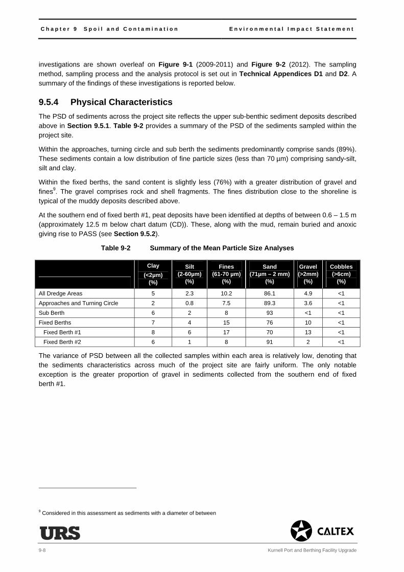
C h a p t e r 9 S p o i l a n d C o n t a m i n a t i o n E n v i r o n m e n t a l I m p a c t S t a t e m e n t
9-8 Kurnell Port and Berthing Facility Upgrade
investigations are shown overleaf on Figure 9-1 (2009-2011) and Figure 9-2 (2012). The sampling method, sampling process and the analysis protocol is set out in Technical Appendices D1 and D2. A summary of the findings of these investigations is reported below.
9.5.4 Physical Characteristics The PSD of sediments across the project site reflects the upper sub-benthic sediment deposits described above in Section 9.5.1. Table 9-2 provides a summary of the PSD of the sediments sampled within the project site.
Within the approaches, turning circle and sub berth the sediments predominantly comprise sands (89%). These sediments contain a low distribution of fine particle sizes (less than 70 µm) comprising sandy-silt, silt and clay.
Within the fixed berths, the sand content is slightly less (76%) with a greater distribution of gravel and fines9. The gravel comprises rock and shell fragments. The fines distribution close to the shoreline is typical of the muddy deposits described above.
At the southern end of fixed berth #1, peat deposits have been identified at depths of between 0.6 – 1.5 m (approximately 12.5 m below chart datum (CD)). These, along with the mud, remain buried and anoxic giving rise to PASS (see Section 9.5.2).
Table 9-2 Summary of the Mean Particle Size Analyses
Clay (<2µm)
(%)
Silt (2-60µm)
(%)
Fines (61-70 µm)
(%)
Sand (71µm – 2 mm)
(%)
Gravel (>2mm)
(%)
Cobbles (>6cm)
(%)
All Dredge Areas 5 2.3 10.2 86.1 4.9 <1
Approaches and Turning Circle 2 0.8 7.5 89.3 3.6 <1
Sub Berth 6 2 8 93 <1 <1
Fixed Berths 7 4 15 76 10 <1
Fixed Berth #1 8 6 17 70 13 <1
Fixed Berth #2 6 1 8 91 2 <1
The variance of PSD between all the collected samples within each area is relatively low, denoting that the sediments characteristics across much of the project site are fairly uniform. The only notable exception is the greater proportion of gravel in sediments collected from the southern end of fixed berth #1.
9 Considered in this assessment as sediments with a diameter of between 61-70 µm

EDEDED
EDEDED
ED
ED
ED
ED
ED
ED
ED
ED
ED
ED
ED
EDEDEDED
EDEDEDED
EDEDEDED
EDEDED
ED
ED
ED
ED
EDEDEDEDED
EDEDEDED
ED
ED
EDED
EDED
ED
EDEDED
FixedBerth #2
FixedBerth #1
SubBerth
TurningCircle
BB oo tt aa nn yy BB aa yy SS hh ii pp pp ii nn gg CC hh aa nn nn ee ll
Approaches
VC4AVC4A
VC4A SS4D
SS4C SS4BSS2D SS2C
SS2B
SS2A
VC2AVC2AVC2A
SS5D
SS5C
SS5B
SS5A
VC5AVC5A
VC5A
VC4DVC4D
VC4D
VC4CVC4C
VC4C
VC4BVC4B
VC4B
SS4J
SS4ISS4H
SS4G
SS4F
SS4E
SS4A
SS1D
SS1CSS1B
SS1A
VC1BVC1B
Figure:
Rev. A4
9-1
KURNELL PORT AND BERTHING PROJECT
This
drawin
g is s
ubjec
t to C
OPYR
IGHT
.
/
A
0 75 150 225 30037.5Meters
Datum: GDA94Grid: MGA Zone 56
File No: 43177771.054.mxd Drawn: STB Approved: CF Date: 07/01/2013
Whilst every care is taken by URS to ensure the accuracy of the digital data, URS makes no representation or warranties about its accuracy, reliability, completeness, suitability for any particular purpose and disclaims all responsibilityand liability (including without limitation, liabili ty in negligence) for any expenses, losses, damages (including indirect or consequential damage) and costs which may be incurred as a result of data being inaccurate in any way for any reason. Electronic files are provided for information only. The data in these files is not controlled or subject to automatic updates for users outside of URS.
SAMPLING LOCATIONS2009-2011
Source: Aerial Imagery - Nearmap Hypertiles 2012.
BOTANY BAY, NSW
LegendED Sampling Location 2009-2011
Dredge Footprint
Project Site
Submarine Pipelines
Project Site
B o t a n y B a y
Botany BayNational Park
FixedBerth #2 Fixed
Berth #1
SubBerth
Kurnell Wharf
TurningCircle
BB oo tt aa nn yy BB aa yy SS hh ii pp pp ii nn gg CC hh aa nn nn ee ll
Breasting Island
Approaches
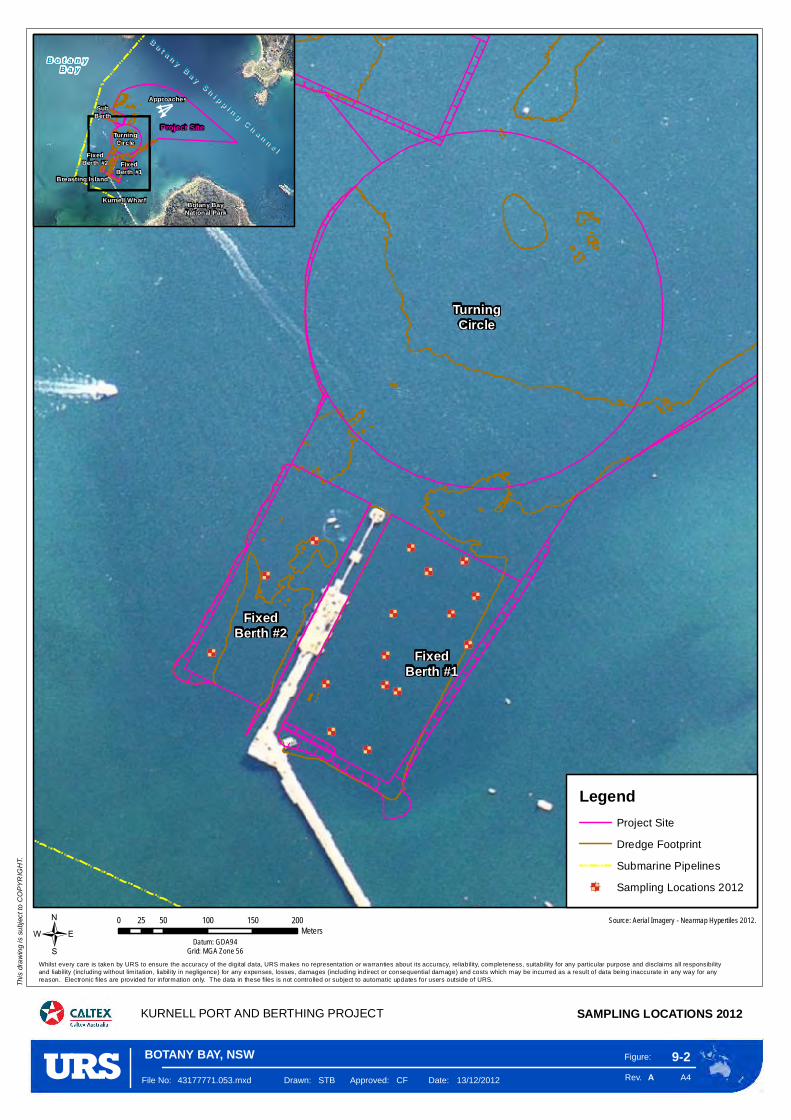
ED
ED
ED EDED
ED
ED ED
ED
ED
ED
ED
ED
ED
ED
ED
FixedBerth #2
FixedBerth #1
SubBerth #3
TurningCircle
Figure:
Rev. A4
9-2
KURNELL PORT AND BERTHING PROJECT
This
drawin
g is s
ubjec
t to C
OPYR
IGHT
.
/
A
0 50 100 150 20025Meters
Datum: GDA94Grid: MGA Zone 56
File No: 43177771.053.mxd Drawn: STB Approved: CF Date: 13/12/2012
Whilst every care is taken by URS to ensure the accuracy of the digital data, URS makes no representation or warranties about its accuracy, reliability, completeness, suitability for any particular purpose and disclaims all responsibilityand liability (including without limitation, liabili ty in negligence) for any expenses, losses, damages (including indirect or consequential damage) and costs which may be incurred as a result of data being inaccurate in any way for any reason. Electronic files are provided for information only. The data in these files is not controlled or subject to automatic updates for users outside of URS.
SAMPLING LOCATIONS 2012
Source: Aerial Imagery - Nearmap Hypertiles 2012.
BOTANY BAY, NSW
LegendProject Site
Dredge Footprint
Submarine Pipelines
ED Sampling Locations 2012
Project Site
B o t a n y B a y
Botany BayNational Park
FixedBerth #2 Fixed
Berth #1
SubBerth
Kurnell Wharf
TurningCircle
BB oo tt aa nn yy BB aa yy SS hh ii pp pp ii nn gg CC hh aa nn nn ee ll
Breasting Island
Approaches

E n v i r o n m e n t a l I m p a c t S t a t e m e n t C h a p t e r 9 S p o i l a n d C o n t a m i n a t i o n
Kurnell Port and Berthing Facility Upgrade 9-11
9.5.5 Chemical Characteristics Geochemical testing has included conducting a number of physical, chemical and toxicity tests on the collected sediments. The analytical suite of chemicals selected for testing is based on the NAGD recommendations. These chemicals consist of a number of heavy metals, hydrocarbons (and their derivatives), pesticides, polychlorinated biphenyls (PCBs)10 and TBT (see below). Samples collected next to the Wharf have also been tested for volatile organic compounds (VOCs) and semi-volatile organic compounds (SVOCs)11.
Table 2.4 of Technical Appendix D1 and table 6 of Technical Appendix D2 provide a summary of the testing schedules, detailing the analytes and the frequency of testing undertaken between 2009 and 2012. The results of the tests are provided in tables 3.2 and 9 of Technical Appendices D1 and D2 respectively.
Concentrations of BTEX12 pesticides, PCBs and volatile compounds were below the analytical limits of reporting (LOR) in all samples collected within the project site. Hydrocarbons (and their derivatives) and heavy metals were detected within sediment samples from the project site. However, the 95% UCL of each area and across the project site was below the guideline limits set for waste classification, site contamination and toxicity for all but one analyte (TBT).
Tributyltin
Tributyltin forms a group of tin-derivative compounds that were used extensively in antifouling paint in the shipping industry until an international ban in 2003 prevented further use. This was followed by a ban on their presence in 2008. Further detail on TBT toxicity and impacts are discussed in Section 10.6.3.
The sampling has shown that TBT occurs extensively across the project site; exceeding the guidance limits for site contamination and toxicity. The mean concentration of TBT found in each of the main areas of the dredge footprint is summarised in Table 9-3.
Table 9-3 Summary of the Geochemical Analysis Results for TBT in Sediments
Criteria Threshold Limit
(µgSn.kg-1)
Aquatic Ecology Threshold Limit ISQG-low 513
ISQG-high 70
Area Results TBT normalised (µgSn.kg-1)
All Dredged Areas
Mean 151
Standard Deviation 504
95% UCL14 of the Mean 255
10 PCBs were commonly used as coolant fluids in items such as transformers and capacitors. 11 VOCs and SVOCs are organic chemicals have high to semi-high vapour pressures. They are numerous and varied. They occur naturally and are man-made (anthropogenic). 12 Benzene, toluene, ethyl benzene and xylene. Volatile organic compounds found in petroleum derivatives. 13 The NAGD includes a revised screening criterion of 9 µgSnkg-1, which has been used for assessment for the purpose of offshore disposal. 14 Upper Confidence Limit:
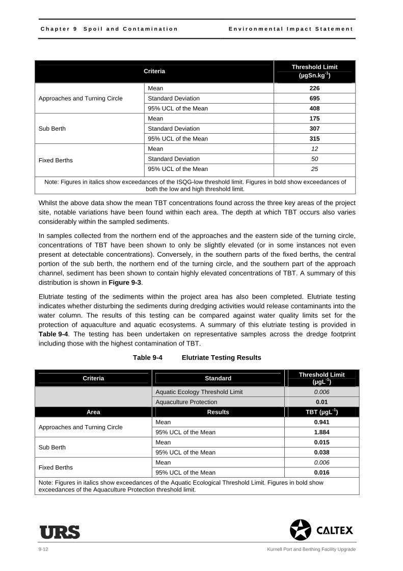
C h a p t e r 9 S p o i l a n d C o n t a m i n a t i o n E n v i r o n m e n t a l I m p a c t S t a t e m e n t
9-12 Kurnell Port and Berthing Facility Upgrade
Criteria Threshold Limit (µgSn.kg-1)
Approaches and Turning Circle
Mean 226 Standard Deviation 695 95% UCL of the Mean 408
Sub Berth
Mean 175 Standard Deviation 307 95% UCL of the Mean 315
Fixed Berths
Mean 12
Standard Deviation 50
95% UCL of the Mean 25
Note: Figures in italics show exceedances of the ISQG-low threshold limit. Figures in bold show exceedances of both the low and high threshold limit.
Whilst the above data show the mean TBT concentrations found across the three key areas of the project site, notable variations have been found within each area. The depth at which TBT occurs also varies considerably within the sampled sediments.
In samples collected from the northern end of the approaches and the eastern side of the turning circle, concentrations of TBT have been shown to only be slightly elevated (or in some instances not even present at detectable concentrations). Conversely, in the southern parts of the fixed berths, the central portion of the sub berth, the northern end of the turning circle, and the southern part of the approach channel, sediment has been shown to contain highly elevated concentrations of TBT. A summary of this distribution is shown in Figure 9-3.
Elutriate testing of the sediments within the project area has also been completed. Elutriate testing indicates whether disturbing the sediments during dredging activities would release contaminants into the water column. The results of this testing can be compared against water quality limits set for the protection of aquaculture and aquatic ecosystems. A summary of this elutriate testing is provided in Table 9-4. The testing has been undertaken on representative samples across the dredge footprint including those with the highest contamination of TBT.
Table 9-4 Elutriate Testing Results
Criteria Standard Threshold Limit (µgL-1)
Aquatic Ecology Threshold Limit 0.006
Aquaculture Protection 0.01 Area Results TBT (µgL-1)
Approaches and Turning Circle Mean 0.941 95% UCL of the Mean 1.884
Sub Berth Mean 0.015 95% UCL of the Mean 0.038
Fixed Berths Mean 0.006
95% UCL of the Mean 0.016 Note: Figures in italics show exceedances of the Aquatic Ecological Threshold Limit. Figures in bold show exceedances of the Aquaculture Protection threshold limit.

Figure:
Rev. A4
9-3
KURNELL PORT AND BERTHING PROJECT
This
drawi
ng is
subje
ct to
COPY
RIGH
T.
AFile No: 43177771.066.mxd Drawn: STB Approved: CF Date: 24/10/2012
Whilst every care is taken by URS to ensure the accuracy of the digital data, URS makes no representation or warranties about its accuracy, reliability, completeness, suitability for any particular purpose and disclaims all responsibilityand liability (including without limitation, liability in negligence) for any expenses, losses, damages (including indirect or consequential damage) and costs which may be incurred as a result of data being inaccurate in any way for any reason. Electronic files are provided for information only. The data in these files is not controlled or subject to automatic updates for users outside of URS.
THE DISTRIBUTION OF TRIBUTYLTIN ACROSS THE PROJECT SITE
Source: Figure provided by Worley Parsons: SAP (May 2011) - Figure 5, 301015-02448_Fig5_TBT Not Normalised to TDC.jpg
BOTANY BAY, NSW

C h a p t e r 9 S p o i l a n d C o n t a m i n a t i o n E n v i r o n m e n t a l I m p a c t S t a t e m e n t
9-14 Kurnell Port and Berthing Facility Upgrade
9.6 Impact Assessment
9.6.1 Introduction The following section assesses the potential impacts associated with the loading, transport and disposal of the dredged sediments.
9.6.2 Reuse and Disposal
Introduction
The chemistry of the sediments, as discussed in Section 9.5.5, has been compared against marine fauna toxicity risks, human health risks, and waste classification criteria to determine if the sediments would be suitable for onshore or offshore disposal, or for reuse within Botany Bay.
Waste Classification
Analysis from Worley Parsons has determined that the proposed dredged materials would be suitable for disposal onshore as general solid waste when compared against the NSW Waste Classification Guidance 2009.
However due to the elevated TBT concentrations, it has been considered that there may be restrictions if these materials were to be disposed at a licenced landfill. Also, if dewatering were to take place prior to disposal, consideration would need to be given to the quality and management of the water removed and its specific treatment and disposal. Therefore, landfill disposal has not been considered a viable option for the sediment.
Reuse (Onshore)
Analysis from Worley Parsons has also determined that the proposed dredged sediments satisfy the health screening levels for use on open spaces and recreational areas (NEPM Category C, see Section 9.4.2). However, the above screening levels do not include a criterion for the reuse of sediments that contain TBT.
The viability of reusing the sediments onshore has been discussed with NSW Department of Primary Industry (DPI) (Fisheries) and NSW Environment Protection Authority (EPA). Both agencies have confirmed that despite meeting the screening levels established in the NEPM, the presence of TBT and its potential impacts on human health would preclude this as an option.
Reuse (Offshore)
Further analysis by Worley Parsons has differentiated areas in the turning circle and approaches where the TBT concentration within sediments is below NAGD-low Screening levels for TBT (9 µgSn.kg-1) (see Figure 9-3). Sediments from these areas would be reusable within Botany Bay. Further calculations have been undertaken to refine the analysis. These have confirmed the suitability for up to 7,800 m3 of the dredged sediments to be available for reuse within the Bay (see Technical Appendix D1). These conclusions have resulted in the proposal to reuse 6,000 m3 of dredged material to cover two exposed sections of the subsea fuels pipelines behind the sub berth and a former anchor point (see Section 4.4.9). The dispersion of these sediments within the marine environment has been included in the modelling simulation scenarios considered in Chapter 10, Water and Sediment Quality, and shown not to result in a significant impact. The ecology of these areas has also been assessed and shown not to contain any threatened species, populations or communities (see Chapter 11, Ecology).
E n v i r o n m e n t a l I m p a c t S t a t e m e n t C h a p t e r 9 S p o i l a n d C o n t a m i n a t i o n
Kurnell Port and Berthing Facility Upgrade 9-15
Offshore Disposal
Following discussions with NSW DPI (Fisheries) and NSW EPA, backed by the analysis undertaken by
Worley Parsons, it was concluded that the majority of the dredged sediments would be disposed of at the
Sydney Offshore Spoil Ground. This site has been used for the disposal of spoil from dredging operations
around the Sydney area since 1984, following the passing of the Environment Protection (Sea Dumping)
Act 198115
. The Sydney Offshore Spoil Ground was specifically set up by Government for the primary
purpose of offshore disposal despite being used for other activities such as commercial and recreational
fishing.
In accordance with the NAGD Guidelines, in order to assess the suitability for offshore disposal, the
marine water quality trigger values (see Table 9-1) should not be exceeded after allowing for initial
dilution (i.e. defined as the mixing that would occur within four hours of disposal).
Numerical dilution modelling has been undertaken using the physical, geochemical and elutriate
properties of the most highly contaminated materials that were found in the turning circle (see Tables 9-3
and 9-4). Results have shown that after this period of initial dilution, the maximum concentration of TBT
that would occur at the Sydney Offshore Spoil Ground would be less than or equal to 8.9 x 10⁻⁵
µgL-1
,
which is well below the limit of 0.006 µgL-1
.(see section 3.2.6.1 Technical Appendix D1)16
.
Chemical and toxicity tests have also been undertaken to provide additional support for offshore disposal.
Two tests were undertaken to consider toxicity. The first looked at the toxicity of the TBT in the sediments
(sediment-bound or whole sediment toxicity). The second looked at the toxicity of TBT in the water
column (elutriate toxicity). Both toxicity tests depend on how bioavailable the TBT is (i.e. how easy it
would be for the TBT to be taken up by sensitive marine biota) and what the subsequent health
(development and reproduction) effects the bioavailable concentrations of TBT would potentially have
following uptake.
The sediment-bound toxicity tests used the most contaminated sediments from within the project site (see
Table 9-2) to assess any reproduction effects on a marine crustacean sensitive to TBT. The elutriate
toxicity test used the highest elutriate results (see Table 9-3) to assess any development effects on
oysters (which are sensitive to TBT). The results confirmed that the sediments were non-toxic (despite
their elevated concentrations of sediment bound TBT) and that there was no detectable toxicity within the
elutriate TBT. As such, it was concluded that TBT would be unlikely to cause toxic effects to benthic
organisms at the Sydney Offshore Spoil Ground (see Technical Appendix D1). For this reason
unconfined offshore disposal has been proposed in the SDP application to the Commonwealth.
9.6.3 Acid Sulphate Soils
Whilst the assessment of ASS confirms both their potential and existence within the Bay sediments, it is
unlikely that acid conditions would be generated during the proposed works as the sediments would be
disposed of or reused below the water surface.
The transfer and transport of materials from the project site to the offshore disposal ground would be
undertaken in split hopper barges. Whilst exposed and open to the air during this period of time, the
sediments would remain saturated. Given the short transport time of 5-6 hours between the project site
and the disposal ground there would be limited potential for the sediments to dry and oxidise. The risk
would be raised however if there was to be a delay in the split hopper barges moving offshore.
15 Lincoln-Smith et al. 1992
16 The above units (µgL
-1) are measured as the quantity of dissolved TBT (in micrograms (µg) (one millionth of a gram)) in one litre
(l) of water. It can also be written µg/l. The results show that the concentration was approximately 67 times below the threshold limit.
C h a p t e r 9 S p o i l a n d C o n t a m i n a t i o n E n v i r o n m e n t a l I m p a c t S t a t e m e n t
9-16 Kurnell Port and Berthing Facility Upgrade
9.7 Mitigation
9.7.1 Discussion
The proposed works would involve the disturbance and dispersal of sediments containing high
concentrations of TBT. Associated impacts to the environment of Botany Bay through this process have
been assessed in detail in Chapter 10, Water and Sediment Quality. The following mitigation measures
relate to the mitigation and management of the materials when being loaded, transported and disposed at
sea.
9.7.2 Management
The Sydney Offshore Spoil Ground has been specifically selected for sea dumping by the Commonwealth
as it is both deep and unaffected by strong currents and the effects of wave action. However, there would
be a requirement to manage the transport and disposal process to reduce the risk of impacts upon the
receiving environment of the offshore disposal ground. The works would be managed under a Dredge
and Spoil Disposal Management Plan (DSDMP). In addition to the DSDMP, Caltex has also been
required to prepare a Remediation Action Plan (RAP) as the proposed works also constitute ‘remediation’
of the project area by removing contaminated materials. The action plan contains the mitigation and
management measures included in the EIS and is located in Technical Appendix O.
Relevant mitigation and management measures covering the loading, transport and disposal of the
dredged sediment would be included in the DSDMP. This information would be used to inform the RAP.
The main mitigation in Botany Bay would be not to allow overflow dredging to take place in the fixed
berths and the approach to the sub berth. The dredging would also include measures to ensure the
sediments would be lifted and loaded so as to prevent any excessive disturbance and agitation, whilst
preventing excessive spillage. This would include the following measures:
• The use of a backhoe is inherently accurate compared to other alternatives (see Chapter 2, Needs
and Alternatives). This means that comparatively, the chosen dredging method would minimise
sediment dispersion.
• Overflow dredging operations would be limited (and if required ceased) to prevent any notable
sediment dispersion (see Chapter 10, Water and Sediment Quality).
• The dredger would make use of a closed bucket to minimise sediment spill when lifting the backhoe
through the water column and when undertaking slewing.
• Accurate positioning systems (e.g. GPS) would be used on the dredgers to ensure direct impacts are
restricted to the approved dredging area and to ensure the over-dredging limit is minimised.
• Hopper doors would be kept in good condition to minimise loss of sediment during transport.
• Dredging activities would be restricted to locations shown on the dredging plan(s).
• Dredging activities would be conducted using equipment that is regularly serviced and registered, and
which complies with the conditions of relevant approvals.
Other management controls for inclusion in the DSDMP relevant to water quality, ecology and underwater
noise are set out in their respective technical chapters. An outline of the content of the DSDMP is
included in Section 19.3.

E n v i r o n m e n t a l I m p a c t S t a t e m e n t C h a p t e r 9 S p o i l a n d C o n t a m i n a t i o n
Kurnell Port and Berthing Facility Upgrade 9-17
9.7.3 Acid Sulphate Soils
As outlined in Chapter 4, Proposed Works Description the BHD would remove dredged sediment from the seabed in a bucket, lifting it through the water column before slewing and releasing it into an adjacent split hopper barge. The dredged sediment would also include a volume of surplus water. The volume of
surplus water depends on the composition of what is being dredged and can be considerable, especially in areas of softer sandier sediment, such as those that are present within the majority of the dredge footprint.
The process would involve deposition of material below the water level under stable non-oxidising
conditions. Given that ASS or PASS materials would remain submerged throughout the process, the overall risk of adverse ecological effects from PASS is considered to be low. As such, the need to prepare an acid sulphate soils management plan (ASSMP) in accordance with ASSMAC guidance is not deemed
necessary for the proposed works.
Measures would be included to monitor the sediments in transit (either to the offshore disposal ground or reuse locations (see Section 4.4.9)) to ensure they would not dry out (particularly during the summer months or if there was a delay in moving the hopper offshore) (see Table 4-5). Where required, the sediments would be sprayed with sea water and kept moist during transit to prevent drying. These provisions would be carried through to the contractor specifications and included under the provisions of the Construction Environmental Management Plan (CEMP), also prepared to support the infrastructure component of the proposed works, and the DSDMP (see Chapter 19, Mitigation and Management Measures).
9.7.4 Summary Table 9-5 outlines the mitigation and management measures that would be put in place to manage the loading, transport and disposal of the dredged sediments.

C h a p t e r 9 S p o i l a n d C o n t a m i n a t i o n E n v i r o n m e n t a l I m p a c t S t a t e m e n t
9-18 Kurnell Port and Berthing Facility Upgrade
Table 9-5 Spoil and Contamination Mitigation and Management Measures
Mitigation and Management Measures Implementation
Design Implementation Operation
The DSDMP and RAP would contain controls and measures to ensure that no overflow dredging operations were to take place at the contaminated area in the approach to the sub berth and in the fixed berths. Further restrictions on spill rate could be introduced, or in extreme cases, overflow dredging would be halted temporarily in favour of removing excess water offshore to further limit sediment dispersion. The DSDMP and RAP would also include measures to ensure the sediments would be lifted and loaded so as to prevent any excessive disturbance and agitation, whilst preventing excessive spillage. This would include a need for the following measures.
The dredger would make use of a closed bucket to minimise sediment spill when lifting the backhoe through the water column and when undertaking slewing.
Accurate positioning systems (e.g. GPS) would be used on the dredgers to ensure direct impacts are restricted to the approved dredging area and to ensure the over-dredging limit is minimised.
Hopper doors would be kept in good condition to minimise loss of sediment during transport.
Dredging activities would be restricted to locations shown on the dredging plan(s).
Dredging activities would be conducted using equipment that is regularly serviced and registered, and which complies with the conditions of relevant approvals.
With regard to the management of ASS, the dredged sediments would be monitored during transit to ensure they would not dry out (particularly during the summer months or when there was any delay in moving the hopper offshore). Spraying the sediments with sea water would be undertaken if there was evidence of drying. These measures would be included in the CEMP and DSDMP specifications.