kt 76/78 transponder installation manual 006 … · facility in accordance with the installation...
TRANSCRIPT

KT 76/78 TRANSPONDER
INSTAllATION MANUAL 006-0067-01
R E\1. 1 DE CE MBER, 1972

This equipment manufactured under the following U.S. Patent: 3, 366,834
ONE FULL YEAR WARRANTY
General Aviation Avionic products manufactured by King Radio Corporation (hereinafter called King) are warranted against defects in design, workmanship and material under normal use for which intended for one year after warranty registration provided such registration occurs within eighteen months of the factory shipping date.
King's limit of liability hereunder shall be to provide necessary parts and labor to repair said product, transportation charges prepaid at either King factory or an authorized King Service Center. King shall not be liable for consequential or other damage or expense whatsoever therefore or by reason thereof.
This warranty shall not apply to any product which has not been installed by an authorized King Installation Facility in accordance with the Installation manual, or which has been repaired or altered in any way so as to adversely effect Its performance or reliability, or which has been subject to misuse, contamination, negligence or accident.
This warranty Is in lieu of all other General Aviation Avionics guarantees or warranties expressed or implied. King reserves the right to make design changes. additions to and Improvements in its products without obligation to install such in products previously manufactured.
0 0 0 D 0 D
D
0 0 0
0 0 D
D 0 0 0 D
411iedSignal AEROSPACE
BENDIX/KING® Service Aid
AlliedSignal General Aviation Avionics 400 Norrh Rogers Road Olarhe, Kansas 66062-1212
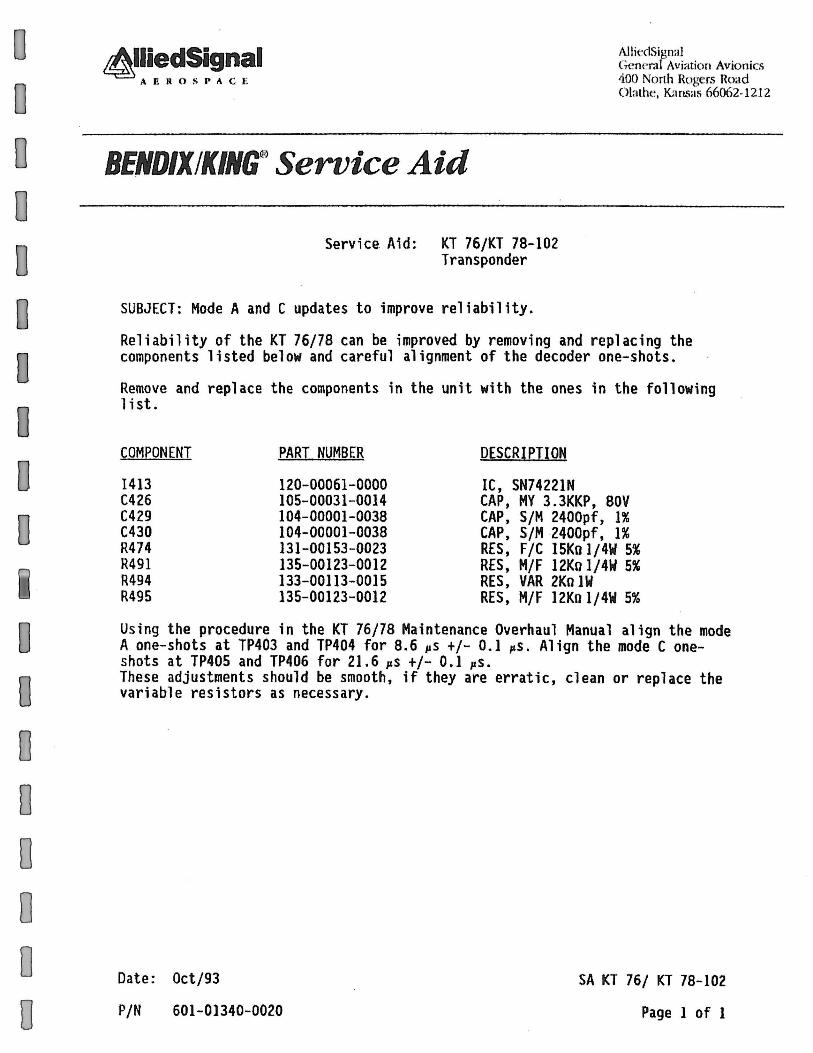
Service. Aid: KT 76/KT 78-102 Transponder
SUBJECT: Mode A and C updates to improve reliability.
Reliability of the KT 76/78 can be improved by removing and replacing the components listed below and careful alignment of the decoder one-shots.
Remove and replace the components in the unit with the ones in the following list.
COMPONENT PART NUMBER DESCRIPTION
1413 120-00061-0000 IC, SN74221N C426 105-00031-0014 CAP, MY 3.3KKP, BOV C429 104-00001-0038 CAP, S/M 2400pf, 1% C430 104-00001-0038 CAP, S/M 2400pf, 1% R474 131-00153-0023 RES, F/C 15Kolj4W 5% R491 135-00123-0012 RES, M/F 12Ko1/4W 5% R494 133-00113-0015 RES, VAR 2Ko 1W R495 135-00123-0012 RES, M/F 12Ko1j4W 5%
Using the procedure in the KT 76/78 Maintenance Overhaul Manual align the mode A one-shots at TP403 and TP404 for 8.6 pS +/- 0.1 pS. Align the mode C oneshots at TP405 and TP406 for 21.6 pS +/- 0.1 ps~ These adjustments should be smooth, if they are erratic, clean or replace the variable resistors as necessary.
Date: Oct/93
P/N 601-01340-0020
SA KT 76/ KT 78-102
Page 1 of 1
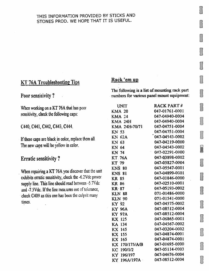
THIS INFORMATION PROVIDED BY STICKS AND STONES PROD. WE HOPE THAT IT IS USEFUL.
J(T 76A Troubt~hootin2 Tips
Poor sen$itivity ?
When working on a KT 76A that has poor sensitivity, check the following caps:
C440, C441, C442, C443, C444.
· If these caps are black in color, replace them all . The new ~ps will be ):ellow in color.
Erratic sensitivity?
. When repairing a KT 76Ayou discover that the unit exhibits erratic sensitivity, check the ·6.2Vdc power supply line. This line should read between ·5.7Vdc and -7.5Vdc.lfthe line mea:;ures out of tol~rance,
·check C409 as this one has been the culprit many times.
Rack 'em up
The following is a list of mounting rack part . numbers for various panel mount equipment:
l;JNIT KJ\.-1A 20 KMA 24 KMA 24H KMA 24H-70171 KN · 53 KN 62A lC~ 63 Kl'l 64 KN 74 KT. 76A KT 79 KNS 80 KNS 81 KR 85 KR 86 KR- 87 K.LN 88 KLN .90 KY 92 KY 96A KY 97A KX 125 KA 134 K.X 145 KX; 155 KX 165 KX 170/175/A/B KC 190/1/2 KY l96/l97 KY 196Nl97A ·
RACK PART# 047-01761-0001 047-04940-0004 04 7-04940-0004 047-0475 1-0004 047-04751-0004 047-04543-0002 04 7-04219-0000 047-04543-0002 047-02191-0000 047-Q3898-0002 047-05827-0004 047-05547-0001 047-04899-0001 047-0 l 846-0000 04 7-025 I 0-0001 047-05193-0002 071-01486-0000 071-01541-0000 047-04575-0002 047-08512-0004 04 7-08512-0004 047-06865-0001 047-04567-0002 047-03204-0002 047...04874-000 i 047-04874-0001 047-01695-0000 047-05114-0003 047-04676-0004 047-08512-0004
0 0 0 0 0 0 0 0 0 0
0 0 0 0 0 0 0 0
0 0 0 D
0 0 D
0 0 D
0 0 D
0 0 0 0 0
~
KING KT 76/78
TRANSPONDER
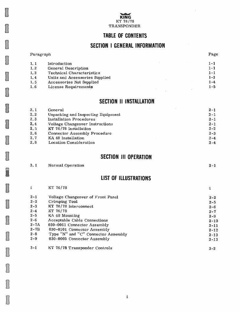
TABLE OF CONTENTS
SECTION I GENERAL INFORMATION Paragraph
1. 1 Introduction 1. 2 General Description 1. 3 Technical Characteristics 1. 4 Units and Accessories Supplied 1. 5 Accessories Not Supplied 1. 6 Lie ense Requirements
SECTION II INSTALLATION 2, 1 2.2 2.3 2.4 2. 5 2. 6 2.7 2.8
3. 1
i
2-1 2-2 2-3 2-4 2-5 2-6 2-7A 2-7B 2- 8 2-9
3-1
General Unpacking and Inspecting Equipment Installation Procedures Voltage Changeover Instruction~; KT 76/78 Installation Connector As sembly Procedure KA 48 Installation Location Considera tion
SECTION Ill OPERATION Normal Operation
LIST OF ILLUSTRATIONS
KT 76/78
Voltage Changeover of Front Panel Crimping Tool KT 76/78 Inte r connect KT 76/78 KA 48 Mounting Acceptable Cable Connections 030-0061 Connector Assembly 030-0101 Connector Assembly Type 11 N11 and "C11 Connector Assembly 030-0005 Connector Assembly
KT 76/78 Transponder Controls
i
Page
1-1 1-1 1-1 1-3 1-4 1-5
2-1 2 - 1 2-1 2-1 2-2 2-3 2-4 2-4
2-1
i
2-2 2-5 2-6 2-7 2-9 2- 10 2-11 2-12 2-13 2-13
3-2
~
KING
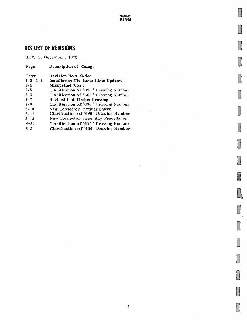
HISTORY OF REVISIONS REV. 1, December, 1972
Front l-3, 1-4 2-4 2-5 2-6 2-7 2-9 2-10 2-11 2-12 2-13 3-2
Description of C:hange
H.evision No's Added Installation Kit Parts Lists Updated Misspelled Word Clarification of "596" Drawing Number Clarification of "696" Drawing Number Revised Installation Drawing Clarification of 11696 11 Drawing Number New Connector Number Shown Clarification o.f 11 696" Drawing "Number New Connector Assembly :Procedures Clarification of 11696" Drawing Number Clarification o1 11 tl96" Drawing Numbe.r
ii
0 0 0 0 0 0 0 0 0 0
0 0 0 0 0 0 0
0 D
0 0 0 0 D
0 0 0
0 0 D
0 0 0 0 0
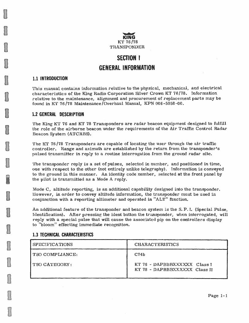
1.1 INTRODUCTION
~ KING
KT 76/78 TRANSPONDER
SECTION I GENERAL INFORMATION
This manual contai ns information relative to the physical, mechanical , and electrical characteristics of the King H.adio Corporation Silver Crown KT 76/78. Information relative to the maintenance, alignment and procurement of replacement parts may be found in KT 76/78 Maintenance/Overhaul Manual, KPN 006-5058-00.
1.2 GENERAL DESCRIPTION
The King KT 76 and KT 78 Transponders are radar beacon equipment designed to fulfill the role of the airborne beacon under the requirements of the Ai.r Traffic Control Radar Beacon System (ATCH.BS).
The KT 76/78 Transponders are capable of locating the user through the air traffic controller. Range and azimuth are established by the return from the transponder's pulsed transmitter in reply to n. routine interrogation from the ground radar site.
The transponder reply is a set of pulses, selected in number, and positioned in time, one with respect to the other (not entirely unlike telegraphy). Information is conveyed to the ground in this manner. An identity code number, s elected at the front panel by the pilot is transm.itted as a Mode A reply.
Mode C, altitude reporting, is an additional capability designed into the transponder. However, in order to convey altitude information, the transponder must be lised in conjunction with a reporting altimeter and operated in "ALT" function.
An additional feature of the transponder and beacon system is the S. P. I. (Special Pulse, Identification). After pressing the ident button the transponder, when interrogated, will reply with a special pulse that will cause the associated pip on the controllers display to "bloom" effecting immediate recognition.
1.3 TECHNICAL CHARACTERISTICS
SPECIF ICATIONS CHARACTERISTICS
TSO COMPLIANCE: C74b
TSO CATEGORY: KT 76 - DAPBBBXXXXXX Class 1 KT 78 - DAPBBBXXXXXX Class II
Page 1-1
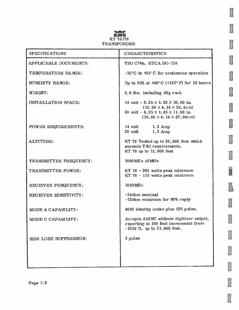
SPECIFICATIONS
APPLICABLE DOCUMENTS:
TEMPERATURE RANGE:
HUMIDITY RANGE:
WEIGHT:
INSTALLATION SPACE:
POWER REQUIREMENTS:
ALTITUDE:
TRANSMITTEH FREQUENCY:
TRANSMITTER POWER:
HECEIVER FREQUENCY:
RECEIVER SENSITIVITY:
MODE A CAPABiliTY:
MODE C CAPABIUTY:
SIDE LOBE SUPPRESSION:
Page 1-2
~
KING KT 76/78
TRANSPONDER
CHARACTEIUSTICS
TSO C74b, UTCA D0-138
- 15° C to +55° C for continuous operation
Up to 95o/o at +50° C ( +122° F) for 12 hours
3. 0 lbs. including Mtg rack
14 volt - 6. 25 X 1. 63 X 10.00 in. ( 15. 88 X 4. ~4 X 25. 4cm)
28 volt- 6. 25 X 1. 63 X 11. 00 in. ( 15. 88 X 4. 14 X 27. 94cm)
14 volt 28 volt
1. 3 Amp 1. 3 Amp
KT 76 Tested up to 30,000 feet which exceeds TSO requirements. KT 78 up to 15, 000 feet
1090MHz ±3MHz
KT 76 - 200 watts peak minimum KT 78 - 113 watts peak minimum
1030M:Hz
-74dbm nominal -72dbm minimum for 90% reply
4096 identity codes plus SPI pulse.
Accepts AIUNC attitude digitizer output, reporting in 100 foot increments from -1000 ft. up to 31,000 feet.
3 pulse
0 D
0 0 0 0 0 0 0 0
[\
0 0 0 0 0 0 0

0 0 0 0 0 0 D 0 0 0
0 0 0 0 0 0 0 0
............. KING
KR 76/78 TRANSPONDER
1.4 UNITS AND ACCESSORIES SUPPLIED
KPN
030-0005-00 030- 0101 - 00
1,< 030-1046-12
030-1050-00
071-1048-00 089-8094-30 090-001 9-07 089- 2013-37 089-5907-06 089-8027-30
1 o91-oo31-os 089-8110-34 089-5903-04
KPN
04 7-2445-00 089-2016-37 089-5991-12 089-8112-34 132-0113-04 089-2009-37 091-0009-00 089-5878-04
A. King K'T 76 Transponder KPN 066-1034-00, 14VDC King KT 76 Transponder KPN 066-1034-01, 28VDC King KT 78 Transponder KPN 066-1034 - 02, 14VDC King KT 78 Transponder KPN 066-1034-03, 28VDC Mounting Tray KPN 047-2439-01 (supplied with each unit)
B. King KT 76/78 Installation Kits
1) KPN 050-1244-00 (14VDC) Parts List as Follows:
DESCHIPTION
Connector Coax, Tf:o~D #4-10-4 Connector Coax, T:ED /19-30-4 Gold Contact Connector, MOL EX 1917G (This is 12 contacts on a strip) Connector, Housing
Antenna KA 48 Washer Flat Retaining Ring Nut, Hex, /16-32 Screw, P. H. P H., #6-32 X 3/8 Washer, F lat, #6 Cable Clamp Lockwasher 1/6 Screw, PHP #4 -40 X 1 /4
QUANTIT Y
1 1 1
1
1 2 1 1 1 1 1 1 2
2) KPN 050-1244-01 (28VDC) Parts list as follows:
-NOTE-
This kit is same as 14 VDC Kit with the addition of the following parts.
D:ESCH.IPT ION
Shield Head Nut Hex 10-32 Screw PHP 10-32 X 3/4 Washer Lock #10 Resistor W/ W 1011, 55W, 5% Nut, Hex, #4-40 Grommet, 1 I 8'' l D. Screw, PHP, #4-40 X 1/4 Springtite
QUANTIT Y
1 2 2 2 1 2 2 2
Hev. 1, December, 1972 Page 1-3
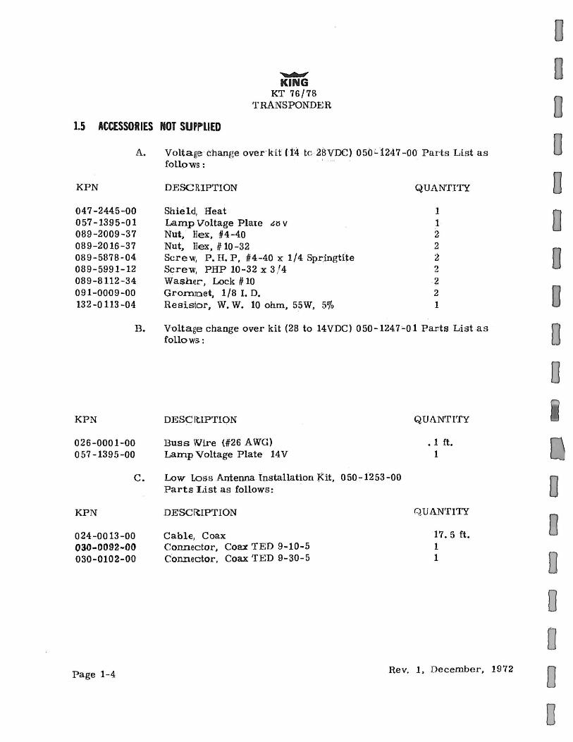
1.5 ACCESSORIES NOT SUfj~-LIED
........_.. KING
KT 76/78 T HANS PONDER
A. Voltage change over kit H'4 to 2SVOC) 050'-1247-00 Parts List as
KPN
047-2445-00 057-1395-01 089-2009-37 089-2016-37 089-5878-04 089-5991-12 089-8112-34 091-0009-00 132-0 113 -04
follows: · ·
DESCRIPTION
Shield, Heat L.amp Voltage Plate &ll v Nut, Rex, #4-40 Nut, Hex, # 10-32 Screw, P. H. P, #4-40 x 1/4 Springtite Screw, PHP 10-32 x 3 / 4 Washer, Lock# 10 Gro.m10et, 1/8 I. D. H.esistor, W. W. 10 ohm, 55W, 5o/o
QUANTITY
1 1 2 2 2 2 2 2 1
B. Voltage change over kit (28 to 14VDC) 050-1247;..01 Parts List as follows:
KPN
026-0001-00 057-1395-00
DESCIUPTION QUANTITY
Buss \Vire (#26 AWG) • 1 ft. Lamp Voltage Plate 14V 1
0 0 0 0 0 0 0 0 0 0
c. Low Loss Antenna Installation Kit, 050-1253-00 o Parts I.J.st as follows:
KPN
024-0013-00 oao.:.oo92-0tl 030-0102-00
Page 1-4
DESCRIPTION
Cable, Coax Connector, Coax 'fED 9-10-5 Connector. Coax 'fED 9-30-5
QUANTITY
17. 5 ft. 1 1
Rev. 1, December, 1972
0 0 0 0 0 0
0 0 0 0 0 0 0 0 0 0
0 0 0 0 0 0 0 D
1.6 LICENSE REQUIREMENTS
~ KING
KT 76/78 TRANSPONDER
The transmitter as installed in the aircraft, requires an Aircraft Radio Station Lice nse. This license is obtained by filing FCC Form 404. The KT 76 or KT 78 may be operated for up to 30 days without a station license, after filing the FCC Form 404 and while awaiting the receipt 0f the station license, providing a copy of the I•'CC Form 404 is kept in the aircraft.
This equipment has been type accepted by the FCC and entered on t heir list of type accepted equipment as King KT 76 or King KT 78 and must be identified as such on your FCC F orm 404, Aircraft Radio Station License Application.
Page l-5
0 0 0 0 0 0 0 0 0 0
0 .0
D
0 0 0 0 D
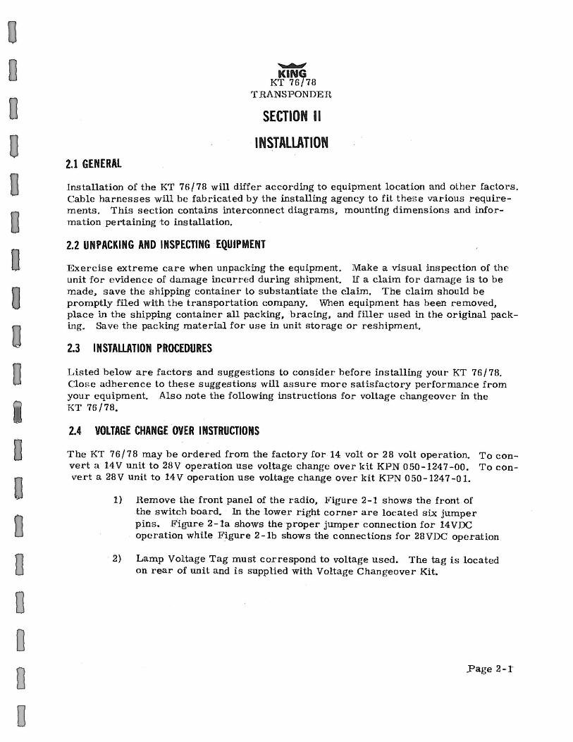
2.1 GENERAL
~
KING KT 76/78
T :RANSPOND.gR
SECTION II
INSTALLATION
Installation of the KT 76/78 will differ according to equipment location and other factors. Cable harnesses will be fabricated by the installing agency to fit these various requirements. This section contains interconnect diagrams, mounting dimensions and information pertaining to installation.
2.2 UNPACKING AND INSPECTING ·EQUIPMENT
Exercise extreme care when unpacking the equipment. Make a visual inspection of the unit for evidence of damage incurred during shipment. If a claim for damage is to be made, save the shipping container to substantiate the claim. The claim should be promptly filed with the transportation company. When equipment has been removed, place in the shipping container all packing, bracing, and filler used in the original packing. Save the packing material for use in unit storage or reshipment.
2.3 INSTALLATION PROCEDURES
Listed below are factors and suggestions to consider before installing your KT 76/78. Close adherence to these suggestions will assure more satisfactory performance from your equipment. Also note the following instructions for voltage changeover in the KT 76/78.
2.4 VOLTAGE CHANGE OVER INSTRUCTIONS
The KT 76/78 may be ordered from the factory for .14 volt or 28 volt operation. To convert a 14V unit to 28V operation use voltage change over kit KPN 050-1247-00. To convert a 28V unit to 14V operation use voltage change overkit KPN 050-1247-01.
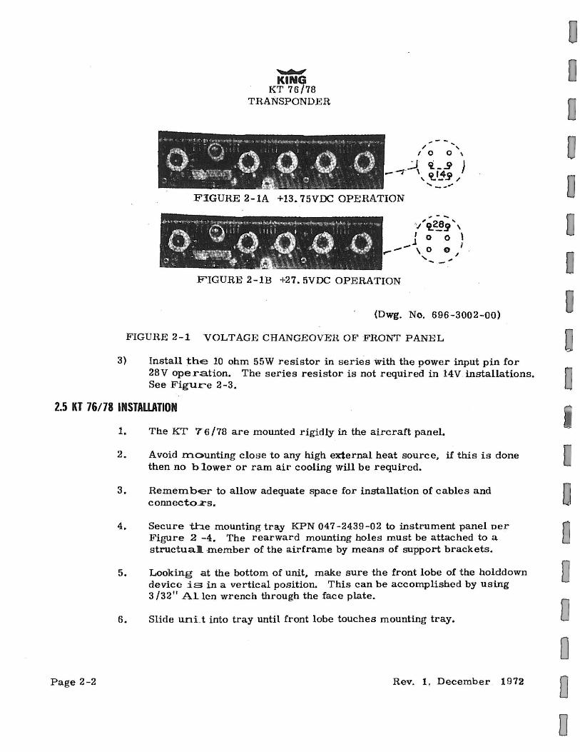
1) :Remove the front panel of the radio, JTigure 2-1 shows the front of the switch board. · In the lower rigb.t corner are located six jumper pins. Ji..,igure 2 -la shows the proper jumper connection for 14 VDC operation while F_igure 2-lb shows the connections for 28VDC operation
· 2) Lamp Voltage Tag must correspond to voltage used. The tag is located oh rear of unit and is supplied with Voltage Changeover Kit.
..Page 2-l
~
KING KT 76/78
TRANSPONDI!~R
... --/ '",
I 0 0 \
..) fi _ _g ) --;· \ a 14a
' "1--..T / ..... __ .,.. F:IGURE 2-lA +13. 75VDC OPERATION
.,.- ... '/tt~!l ', I 0 0 \ j . .
-- \ . o e / ' ... ... -FIGURE 2-1B +27. 5VDC OPERATION
(Dwg. No. 696-3002-00)
l<'IGUH.E 2-1 VOLTAGE CHANGEOVER O.F FRONT PANE L
3} Install the 10 ohm 55W resistor in series with the power input pin for 28V operation. The series resistor is not required in 14V installations. See Figure 2-3.
2.5 KT 76/78 INSTALLATION
Page 2-2
1. The KT 76/78 are mounted rigidly in the aircraft panel.
2. Avoid mounting clos e to any high external heat source, if this is done then no blower or ram air cooling will be required.
3. RemembEr to allow adequate space for installation of cables and connecto~s.
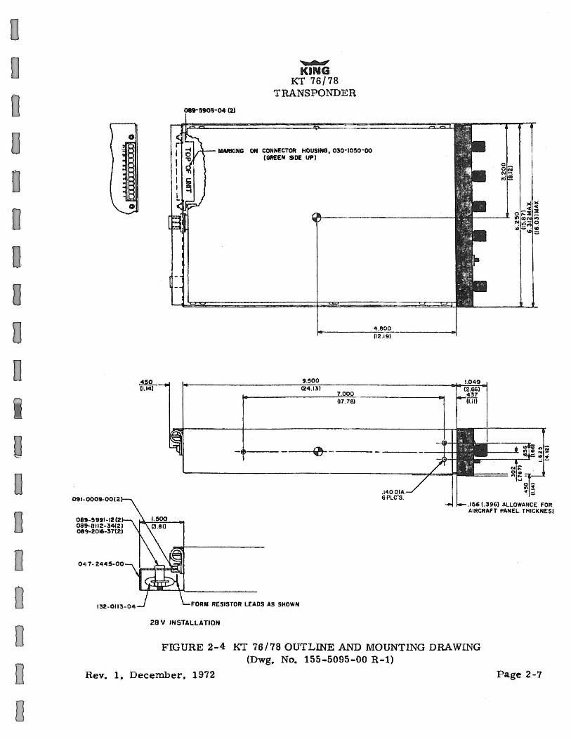
4. Secure the mounting tray KPN 047 - 2439-02 to instrument panel oer Figure 2 -4. The rearward mounting holes must be attached to a structual. ·member of the airframe by means of support brackets.
5.
6.
Looking at the bottom of unit, make sure the front lobe of the holddown device is in a vertical position. This can be accomplished by using 3/32n Allen wrench through the face plate.
Slide uni. t into tray until front lobe touches mounting tray.
Rev. 1, December 1912
0 0 0 0 0

D D
0
0 D
0 0 0 0
0 0 0 Q
0 0 0 D
7.
~ KING
KT 76/78 TH.ANSPONDEH.
Turn Allen wrench clockwise until .rear lobe engages with the tray slot. Continue turning wrench clockwise until tight.
-CAUTION-
Do Not Ove rtighten Locking Screw
8. For removal turn 3/32" Allen wrench counter-clockwise until unit disengages from tray slot. Unit may then be removed.
2.6 CONNECTOR ASSEMBLY PROCEDURE
The KT 76/78 uses a special connector that mates directly with the Printed Circuit noard inside the unit. Assembly of the connector is as follows:
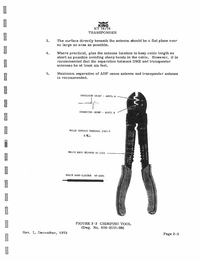
A. Contact Terminal Assembly Using Molex Crimper (Figure 2-2)
B.
1. Strip each wire 5/32" for contact terminal KPN 030-1046-XX. (The last two digits of the contact terminal part number indicate the number of terminals required).
2. Open the Molex Hand Crimper HT1921 with the engraved side . toward the operator. Place the conductor tab section of a contact terminal on Anvil B withthe contact portion facing away from the operator. Close the crimper slightly until the contact tabs touch the female jaw.
3. Insert the stripped conductor until the insulation is even with the side of the crimper facing the operator. Crimp the conductor tabs by squeezing the handles together until the jaws are fully closed or a sufficient crimp is obtained.
4. Move the lead to Anvil A. Place the insulating tab section on Anvil A. Crimp again Until the jaws are fully closed or a sufficient crimp is obtained.
5. If necessary, straighten the contact terminal while it is held by the crimper.
Contact Terminal Assembly Using Pliers 1. Strip each wire 5/32" for contact terminal KPN 030-1046-XX (the
last two digits of the contact terminal part number indicate the number of terminals required).
2. Tin the exposed conductor. 3. Using needle nose pliers fold over each conductor tab in turn, onto
the exposed conductor. When both tabs have been folded, firmly press the tabs against the conductor.
4. Repeat Step 3 for the insulator tabs. 5. Apply a drop of solder (using minimum · heat) to the conductor /tab
connection to assure a good electromechanical joint.
Page 2-3
~ KING
KT 76/78 TRANSPONDER
C. Contact Insertion into Molex Connector Housing 1. After the contact terminals have been installed on the wi ring
harness, the contact terminals can be inserted into the desired location in the connector housing. The terminal cannot be inserted up-side-down. Right side up it slides into place effortlessly. Be sure to push · the terminal all the way in, until a click can be felt, heard, or seen (through the translucent -housing).
2. The self locking feature can be tested by moderately pulling on the wire.
D. Extraction of Contact from Molex Connector If a contact is inserted into the wrong connector position, or if an installation wiring change is desired, the Molex contact can be easily removed. 1. Slip the flat narrow blade of a Molex contact ejector tool, HT -1884,
under the contact on the mating side of the connector. Looking down, the blade can be seen sliding into the stop.
2. When the ejector is slid into place, the locking key of the contact is raised allowing the contact to be removed by pulling moderately on the lead.
3. Neither the contact or position is damaged by removing a contact ·if care is exercised when contact is removed.
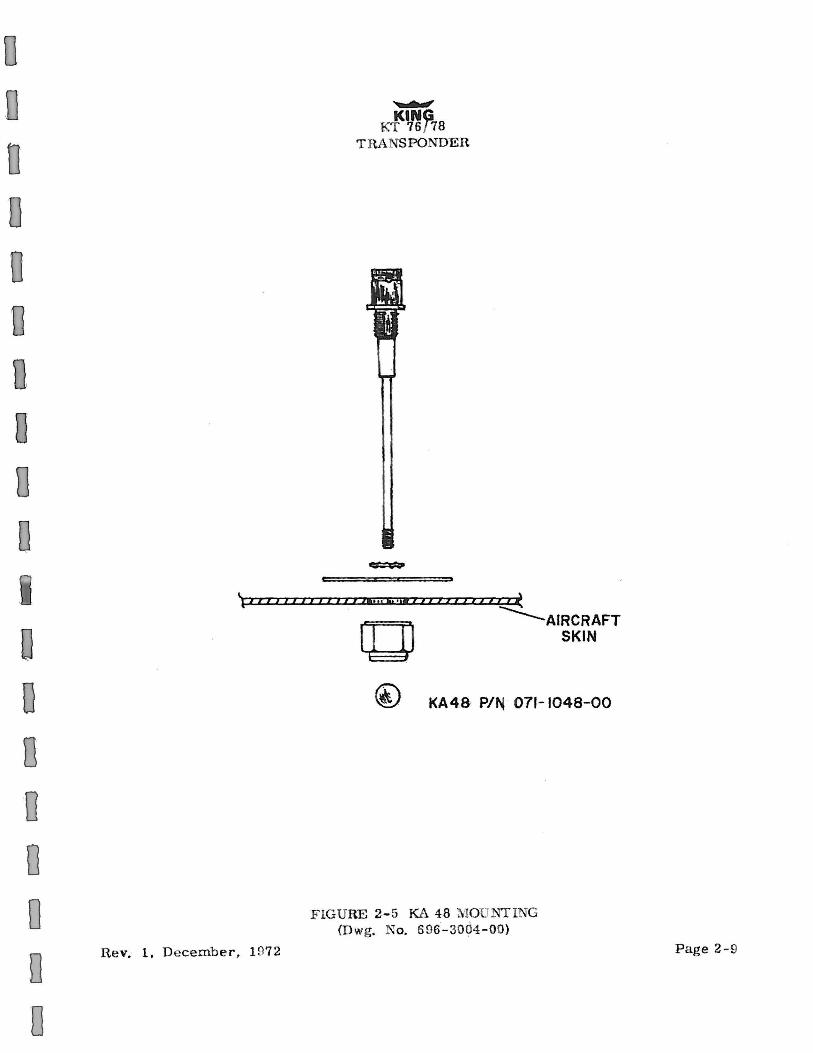
2.7 KA 48 INSTALLAiiON
The KA 4a antenna is a vertical quarter wave dipole designed for optimum performance at the transponder operating frequency. When making the antenna installation guidelines should be taken from an investigation of proven s atisfactory transponder and DME antenna installations.
....:.NOTE-
A . 380 inch clearance hole is required. The antenna should be kept clean. If left dirty (oil covered) the range of the transponder may be affected.
2.8 LOCATION CONSIDERATIONS
1.
2.
Page 2-4
The antenna should be well removed from any projections, the engine( s) and propeller( s).
The antenna should be mounted on a bottom surface that will be level in normal aircraft flight attitudes.
Rev. 1, December, 197.2
D D
0 0 0 0 0 0 0 0
0 0 D
D
0 0
3.
4.
5.
~
KING KT 76/78
TRANSPONDER
The surface directly beneath the antenna should be a nat plane over as large an area as possible.
Where pr·actical, plan the antenna location to keep cable length as short as possible avoiding sharp bends in the cable. However, it is recommended that the separation between DME and transponder antennas be at least six feet.
Maximum separation of ADF sense antenna and transponder antenna is recommended.
lNSUI.IITOR r;R IMP - ANVIL A
I ~, --., :~"··
CONI>li CTOR CRIMP - Al'iV1L B
MOL!!:X CON1'A(,1' TEIL'1INAt. 1 'H 7 -T
4< ·~:
MO LF:X HAND ClllMPER HT·l'J21.
~!OLF.X HAND EJECTOR HT-1884
FIGURE 2-2 CRIMPING .TOOL (Dwg. No. 696-2151-00)
Rev. 1, De:cP.mber, 1972 Page 2-5

NGTE 1
~
KING KT 76/78
TRANSPONDER
r -,/ r --, UND--...... 12 <:;RO
I 1 I 3 c I KT 76/78 ~ I
I 4 ALTITUDE I
6 A
8 c 2 B
4 B 1 DIGITIZER I I ~ 1
I ~ 1
9 A
10 c 1 B
7 A
I T DIMMER ... 3A L _j 75VDC INPUT~'""'_. --
11 LIGH
5 +-13.
1 (030-1045-12)-(CONN:) ~
I (03~-1046-12)(CONTACT) " -
I (030~0061-00) SEE NOTE 3
0-~t.-... -•T .0 KA 48 ANTENNA
L __ __j '-sEE NOTE #4
NOTES:
1. CONNECTOR 'TERMINAL NUMBER IS SPECIFIED ON THE CONNECTOR.
2. A.LL. WillES SHOULD BE #22AWG.
3. HESISTOR USED IN 27. 5VDC OPEHATION ONLY. THIS HF. SISTOR CAN BE MOUl'l'['ED ELSEWHERE IN AIHCRAF'T, BUT THE HEAT SHIELD SHOULD STILL BE USED.
4. ROUTE THE A~TENNA CABLE AS FAR AS PRACTICABLE F ROM ANY HARNESS. INNO CASE SHOULD THE ANTENNA CABLE UE LACED INTO A HARNESS BUNDLE.
F'IGUHE 2-:3 KT 76/78 INTERCONNECT DIAGRAM (Dwg. No. 696-3003-00)
Page 2-6 Rev. l, De<;ember. l!l72
0 0 0 0 D 0 D D 0 D
G 0 0 D
D 0 0 0
0
0 0 D
n D D D
0 0 0 D 0 0
0
091-000$-00(~
089-~911-1212 089-8112-34(2) 089-2016--37(2)
0 4 7- 2445-00
0
~ KING
KT 76/78 TRANSPONDER
IIWIKING ON COHN£CTOfl HOUSING, 030-IO~O-OO I GAEEN SlOE UP)
~ ---
FORM RESISTOR LEADS AS SHOWN
28 V INSTALLATION
(12 .1 9)
FIGURE 2-4 KT 76/78 OUTLINE AND MOUNTING DRAWING (Dwg. No. 155-5095-00 R•l)
Rev. 1. December. 1972 Page 2-7
N'c; IO<D If') • . ,., _ ......
.,-N~ .., . •• --
r
NOTES :
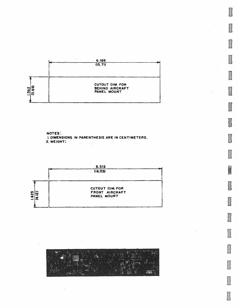
6 .188 (1~. 71)
CUTOUT DIM. FOR BEHIND AIRCRAFT PANEL MOUNT
I. DIMENSIONS IN PARENTHESIS ARE IN CENTIMETERS. 2. WEIGHT;
. 6.312 (16.03)
CUTOUT DIM. FOR FRONT AIRCRAFT PANEL MOUNT
l
l
0 Q
0 0 D 0 u D 0
0 0
Q
0 0 0 0
0 D
n D 0 Q
D D
0
0 D D
0 Q
0 D D
~
KING KT 76 / 78
TRA SPONDER
l ~ ( I I I I I I I I I I I I I lit u L liM I I I I I I I l l I t I ~
. n===it --.:..._AIRCRAFT
Rev. 1. De cemb er, 1972
~ SKIN
KA48 PIN 071-1048-00
FIG URE 2- 5 KA 48 MO . NflNG {Dwg. No. 696-3004-00)
P age 2-9
,...,.,. K'f-<~~8
T RANSPO DER
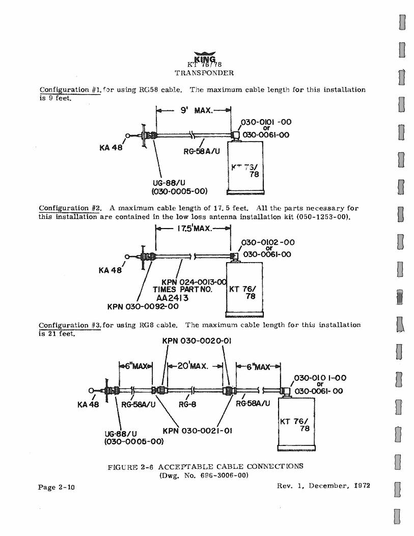
Configuration #1. f ·:>r us ing RG 58 cabl e. T he maximum cabl e l ength for t his installa tion is 9 feet.
UG-88/U (030·0005-00)
}("r 75/ 78
Configuration #2. A maximum cable length of 17. 5 f eet. All t he parts necessary for this installation are cont ained in the low loss antenna installation kit (050-1253-00),
I 17.51MAX.1
~ p3o-o~" -oo I ·y I ) -:1. 030-0061-00
KA48
KPN 024-0013-00 TIMES PART NO. KT 761 AA2413 78
KP-N 03Q-0092-00
Configuration #3. for using RG8 c able. T he maximum cable length for thi~ installation is 21 feet.
Page 2-10
KPN 030-002 D-Ol
r"MAX1 l~201MAX.1~ 16"MAX__. /1 1\ 030-otot-oo f til . I or o-dltJ H 9L I u ®.1 ~ ~ 03D-0061- 00 I \I .\I l I KA 48 RG-58A/U RG-8 RG-58A/U
UG·BSIU KPN 030-Q021-01 (030-0005-00}
KT 76/ 78
FIGURE 2-6 ACCEPTABLE CABLE CONNE CT IO NS (Dwg. No. 696-3006-00)
Rev. 1, D e cember, 1972
0 D D 0 0 0 Q
D
0 D
{}
D 0 D 0 0 0 0
0 0 0
n
D IJ
0 Q
0 0 D D
~
KING KT 76/78
TH.A . ~SPONDER
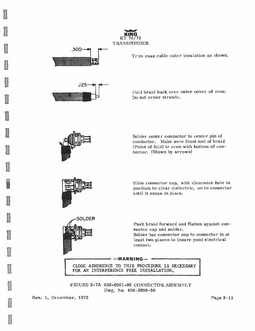
Trim coax cable oute r insulation as shov.rn.
F o d braid back over ou tcr cover of coax. Do not cross strands.
Solder center conductor to center pin of conductor. Make sure front end of braid (Point of fold ) is even with bottom of connect or. (Shown by arrows)
Slide connector cap, with clearanee hole in position to c lear dielectric, on to connector unti.l it snaps in place.
Push braid forward and flatten a gainst connector cap and solder. Solder tac connector cap to connector in at least two pl ace s t o insure good e l ectrical contact.
.----------WARNING-
CLOSE ADHERENCE TO THIS PROCEDURE IS NECESSARY FOR AN I NTERFERENCE FREE INSTALLATION.
FIGURE 2-.7A 030-0061-00 CONJ\TE CTOR ASSEMBLY Dwg. No . 696-3006-00
Rev. 1~ December, 1972 Page 2-11
Page 2-12
..........,. KING
KT 76 / 78 TRA SPONDER
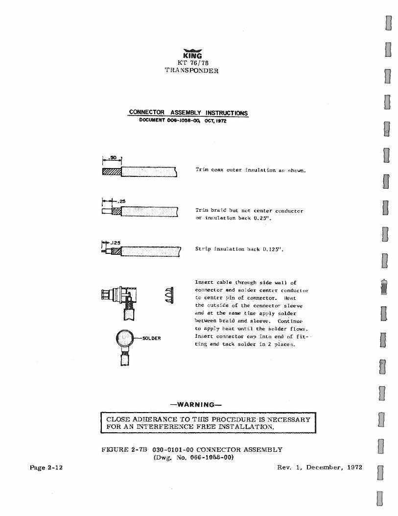
CONNECTOR ASSEMBLY INSTRUCTIONS DOCUMENT OCie-1058·00. OCT, lt12
Tr im coax outer i ns ulation a !! s hown.
Tr im bra i d b ut no t center conductor or ins ulat.ion back 0.25".
St rip i nsul ation back 0. 125".
Insert cable _through side wall of
connector and sol der center conduct or to center pin of connector. Hea t t h e outs i de of the connect a · sleeve
a nd at the same t i we apply solder
between braid and sleeve. Continue to appl y hea t unt ·i l the St>lder flows .
Insert connector cap i nto end of fit- ·
t i ng and tuck solder in 2 pl ace s .
-WARNING-
CLOSE ADUERANCE TO THIS PROCEDURE -IS NECESSARY FOR AN INTERFERENCE FREE INSTALLATIO ' .
FlGURE 2-7B 030-0101-00 CONNECTOR ASSEMBLY (Dwg. No. 066-106.6-00)
Rev. 1, December, 1972
D
0 0 0
0 D
0
D 0
D
0 0 0

0 0 0 0 0
0 D D
0
D 0 0
0 0 D
EXAMPLE
KPN
030-0020-01 - · 030-0021-0 I
~ KING
KT 76/78 THANSPO DEH
SIZE
P lace nut and gaske t over cable and cut jacket to d imension shown.
Comb out b raid and fold out. Cut cable dielectric to dimension shown. Tin center conductor.
P ull bra id wires forward and taper toward c enter conductor. P~ace clamp over braid and pus h back against cab le jacket.
Fold back braid wires as shown, trim to proper length (D) and form over clamp as shown. Solder cont act to center conductor.
Insert cabl e and parts into connector body. ake sure s harp edge of clamp seats pro
perly in gasket. Tighten nut.
DIMENSIONS RG/U CABLE A 8 c D
8 9/32 1/8 5132 3164
58 9/32 1/8 5/32 3/64
FIGURE 2-8 T Y PE " "AND " C'' CONl\TECTOR ASSEMBLY (Dwg. o. 696-3007-00)
FIGURE 2-9 030-0005- 00 CO TEC"fOR ASSEMBLY (Dwg. No. 696-3008-00)
Rev. 1, December, 1972 Page 2-13
0 D.
0 0 0
0
0 0
n D
D D 0 0 0 0
3.1 NORMAL OPERATION
...........,.. Kl'tn~a
T RA -spo DER
SECTION Ill
OPERATION
The transponder is t u rned on by rotating the fu nction sele ctor f rom the off position to any other position.
-NOTE-
T he KT 76 / 78 should be turned off before start ing aircraft enginc(s }.
After being turned on there is a 30 second delay before t he unit becomes functional. This is to permit the t ransmitter tube t o warm-up and stabil ize. Usually the function switch will be rotated to the " s tandby" pos ition, however, any o perative position will initiate the time delay turn on. Any time t hat the function switch i s in the "ON" or 11ALT" position the t ransponder becomes an active pa rt of t he beacon system. rt is undesirable from a syst ems view point to be operat ing (function selector in e ither of these positions) while on the g round, t axiing, o r r unning up a t a t erminal w ith a colocated beacon interrogator. Attention should be paid to the code selected on t he control head. The selected code should b e in accordance with inst ruct ions for IF R flight or rules applicabl e to t rans ponder ut ilizat ion for V F R flight .
--NOTE-
Never activat e the t ransponder with either Code 0000, 7700 or 7777 selected on the control head. Code 7700 is selected for emergencies.
During normal transponder operation, a flashing lamp is an indication o f a t ransmitted reply. An int errogation will normally be at 10 - 15 seconds intervals. Lamp flashes within this interval may be f rom noise, a second or t h ird int errogator, or from side lobes from interrogators without side lobe suppression.
"ON" function will be the c ustomary m ode of operation. If an altit ude digitizer i s part of the system then "ALT" funct ion will be select ed if altit ude reporting is requested by traffic control. "ALT" function enables t he transponder to encode a n altit ud e reply.
The IDENT feature is used at t he reques t of the t raffic cont rolle r . T he ID.ENT button is deprcs~ed momentarily and then r el eased. A memory holds th e IDE . T reply for an interval to a~s ure the proper reply for a t leas t one radar sweep. This memory also turns the reply lamp on steady a s an indication of the ident function.
Page 3- l
Page 3-2
~
KING KT 76 / 78
T RANSPONDER
-NOTE-
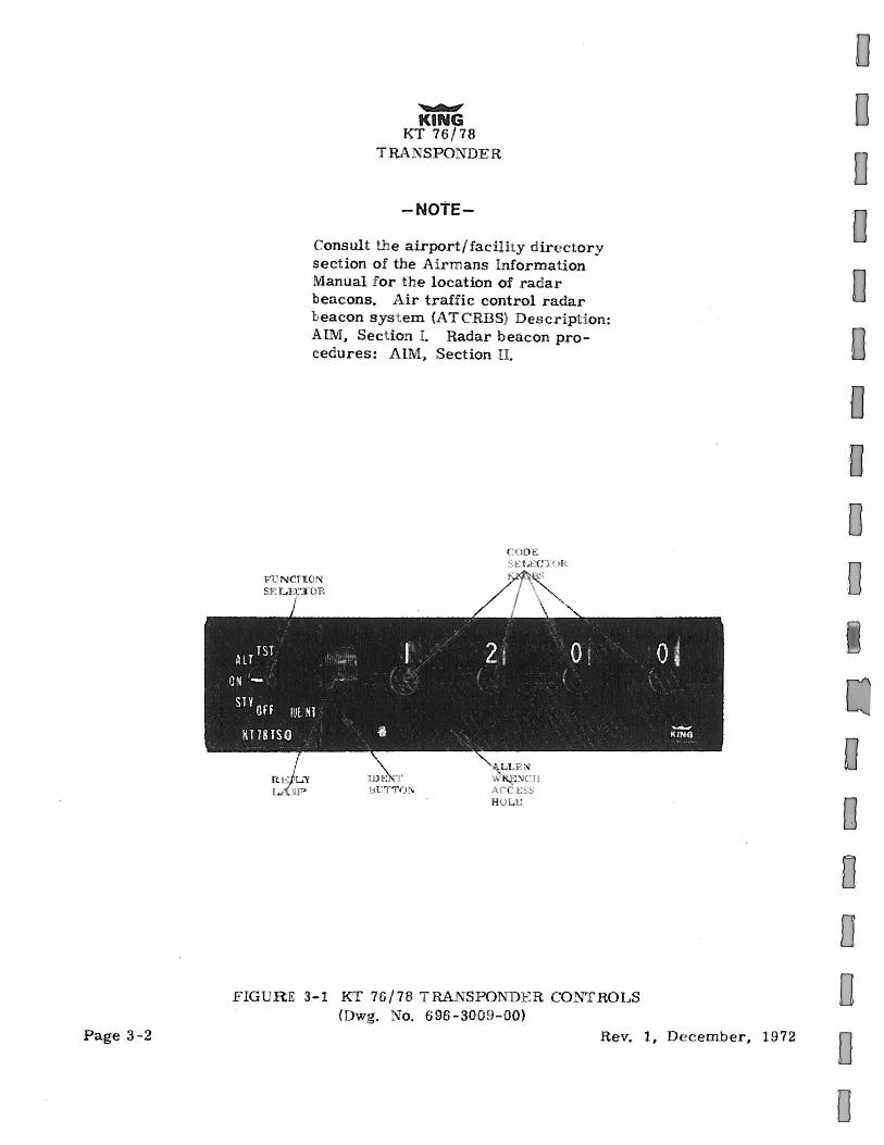
Consult the airport / fac ility dire ctory section of the Airmans Information Manual for the location of r a dar beacons. A ir traffic control radar beacon syst em (AT CRBS) Des c ription : AIM, Section L Radar beacon procedures: AIM, Section II.
CODE S t: U ;C T<..l ll.
F IGUR E 3-1 KT 76/ 78 TRANSP ONDE R CO NTROLS (Dwg. No. 696 - 3009- 00)
Rev. 1, December, 1972
0 0 D
0 0 0 0 0 0 D
0 0 D
0 0 0
0 0 0 0 0 0 0 0 0 0
D
0 0 D 0 0 0 0
INSERTED AS A COURTESY, NOT PART OF THE ORIGINAL MANUAL.
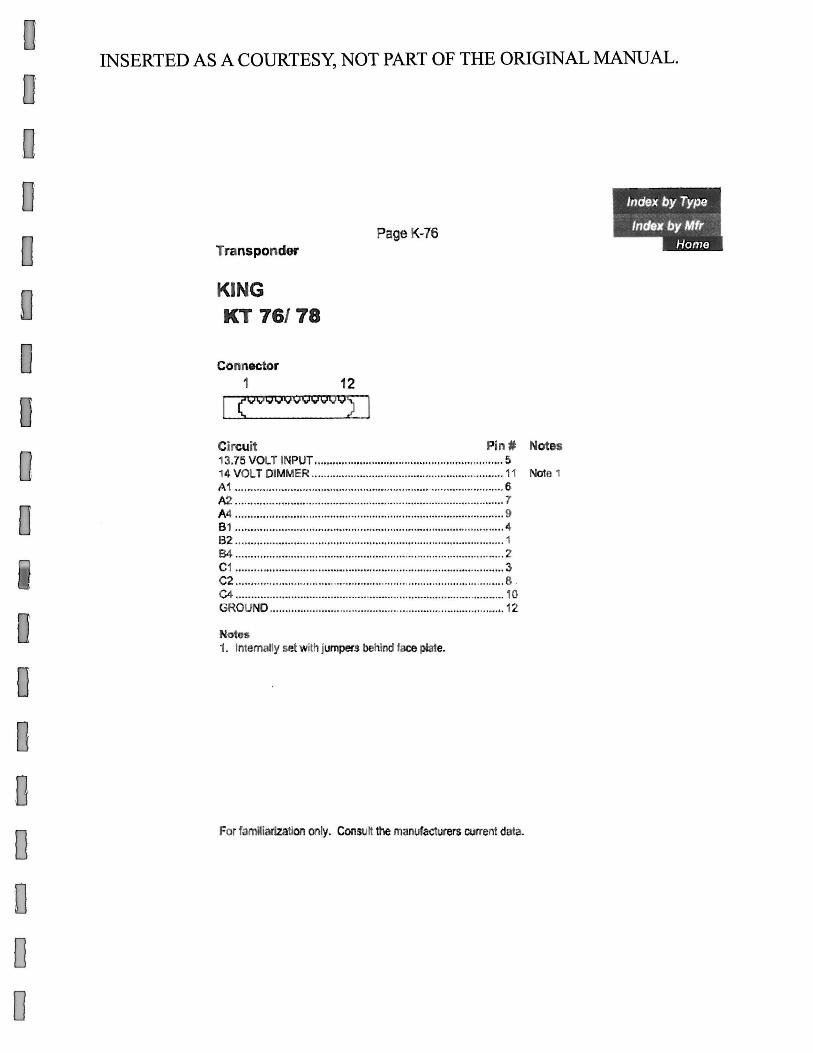
Transpondet"
KING KT 76/78
Connector 1
Page K-76
12
Circuit Pin# Notes 13.75 VOLT INPUT .......... ............................................. ........ 5 14 VOLT DIMMER ........................................ ... ..................... 11 Note 1 A1 ........................ ................................................................. 6 1<:2. ............................ ............. ............. ................................... 1 A4 ........................ ................................................................. 9 8 1 .................................................... ...................................... 4 82 .. .................................. ....................... .............................. 1 84 ... ..................... ........................................... ...................... 2 C1 ....... ...................................................................... ......... ... 3 C2 ............ ............. ................ ........... ... .. .................... ... ......... 6 . C4 ............. ............. ........................................................ ....... 10 GROUN0 ................ ....... .................... ........................... ........ 12
Notes 1. Internally set with jumpers behind face plate.
For familiarization only. Consult the manufacturers current data.