kp-32 user manual - · pdf fileaccident, failure to follow instructions in the service manual...
TRANSCRIPT
9350-7656-000 Rev D, 9/2002
USER INSTRUCTIONS
KP-32 KEYPANEL
EKP-32 EXPANSION PANEL
LCP-32 LEVEL CONTROL PANEL
PROPRIETARY NOTICE
The RTS product information and design disclosed herein were originated by and are the property of Telex Com-munications, Inc. telex reserves all patent, proprietary design, manufacturing, reproduction, use and sales rights thereto, and to any article disclosed therein, except to the extent rights are expressly granted to others.
COPYRIGHT NOTICE
Copyright © 2000 by Telex Communications, Inc. All rights reserved. Reproduction in whole or in part without prior written permission from Telex is prohibited.
UNPACKING AND INSPECTION
Immediately upon receipt of the equipment, inspect the shipping container and the contents carefully for any dis-crepancies or damage. Should there be any, notify the freight company and the dealer at once.
WARRANTY INFORMATION
RTS products are warranted by Telex Communications, Inc. to be free from defects in materials and workmanship for a period of three years from the date of sale.
The sole obligation of Telex during the warranty period is to provide, without charge, parts and labor necessary to remedy covered defects appearing in products returned prepaid to Telex. This warranty does not cover any defect, malfunction or failure caused beyond the control of Telex, including unreasonable or negligent operation, abuse, accident, failure to follow instructions in the Service Manual or the User Manual, defective or improper associated equipment, attempts at modification and repair not authorized by Telex, and shipping damage. Products with their serial numbers removed or effaced are not covered by this warranty.
To obtain warranty service, follow the procedures entitled “Procedure For Returns” and “Shipping to Manufacturer for Repair or Adjustment”.
This warranty is the sole and exclusive express warranty given with respect to RTS products. It is the responsibility of the user to determine before purchase that this product is suitable for the user's intended purpose.
ANY AND ALL IMPLIED WARRANTIES, INCLUDING THE IMPLIED WARRANTY OF MERCHANT-ABILITY ARE LIMITED TO THE DURATION OF THIS EXPRESS LIMITED WARRANTY.
NEITHER TELEX NOR THE DEALER WHO SELLS RTS PRODUCTS IS LIABLE FOR INCIDENTAL OR CONSEQUENTIAL DAMAGES OF ANY KIND.
CUSTOMER SUPPORT
Technical questions should be directed to:
Customer Service DepartmentRTS/Telex12000 Portland Avenue SouthBurnsville, MN 55337 U.S.A.Telephone: (952) 884-4051Fax: (800) 323-0498
RETURN SHIPPING INSTRUCTIONS
PROCEDURE FOR RETURNS
If a repair is necessary, contact the dealer where this unit was purchased.
If repair through the dealer is not possible, obtain a RETURN AUTHORIZATION from:
Customer Service DepartmentTelex Communications, Inc.Telephone: (877) 863-4169Fax: (800) 323-0498
DO NOT RETURN ANY EQUIPMENT DIRECTLY TO THE FACTORY WITHOUT FIRST OBTAINING A RETURN AUTHORIZATION.
Be prepared to provide the company name, address, phone number, a person to contact regarding the repair, the type and quantity of equipment, a description of the problem and the serial number(s).
SHIPPING TO MANUFACTURER FOR REPAIR OR ADJUSTMENT
All shipments of RTS products should be made via United Parcel Service or the best available shipper, prepaid. The equipment should be shipped in the original packing carton; if that is not available, use any suitable container that is rigid and of adequate size. If a substitute container is used, the equipment should be wrapped in paper and surrounded with at least four inches of excelsior or similar shock-absorbing material. All shipments must be sent to the following address and must include the Return Authorization.
Factory Service DepartmentTelex Communications, IncorporatedWest 1st StreetBlue Earth, MN 56013 U.S.A.
Upon completion of any repair the equipment will be returned via United Parcel Service or specified shipper collect.

End-User License Agreement for Telex® Software
IMPORTANT - Please read this document carefully before using this product.
THIS DOCUMENT STATES THE TERMS AND CONDITIONS UPON WHICH TELEX COMMUNICATIONS, INC. (the “COMPANY”) OFFERS TO LICENSE THE INSTALLED SOFTWARE OR PROGRAM (the “SOFT-WARE”) FOR USE WITH THE PRODUCT IN WHICH IT WAS INSTALLED. YOU ARE AGREEING TO BECOME BOUND BY THE TERMS OF THIS AGREEMENT. IF YOU DO NOT AGREE TO THE TERMS OF THIS AGREEMENT, DO NOT USE THIS PRODUCT. PROMPTLY RETURN THE PRODUCT TO THE PLACE WHERE YOU OBTAINED IT FOR A FULL REFUND.
The installed software as supplied by the Company is licensed, not sold, to you for use only under the terms of this license, and the Company reserves all rights not expressly granted to you. You own the product or other media on or in which the Software is originally or subsequently recorded or fixed, but the Company retains ownership of all copies of the Software itself.
1. License: This license allows you to use the Software for internal purposes only on a single product in which it was installed.
2. Restrictions: (a) You may not market, distribute or transfer copies of the Software to others or electronically transfer or duplicate the Software. YOU MAY NOT REVERSE ENGINEER, DECOMPILE, DISASSEMBLE, MODIFY, ADAPT, TRANSLATE, RENT, LEASE OR LOAN THE SOFTWARE OR CREATE DERIVATIVE WORKS BASED ON THE SOFTWARE OR ANY ACCOMPANYING WRITTEN MATERIALS. (b) The Soft-ware and the accompanying written materials are copyrighted. Unauthorized copying of the Software, including portions thereof or the written materials, is expressly forbidden. (c) You understand that the Company may update or revise the Software and in so doing incurs no obligation to furnish such updates to you.
3. Limited Warranty: The Company does not warrant that the operation of the Software will meet your require-ments or operate free from error. The Company DISCLAIMS ALL OTHER WARRANTIES AND CONDITIONS EITHER EXPRESS OR IMPLIED, INCLUDING THE WARRANTIES OF MERCHANTABILITY, FITNESS FOR A PARTICULAR PURPOSE AND NON-INFRINGEMENT OF THIRD PARTY RIGHTS.
4. Limited Liability: The liability of the Company for any claims arising out of this License based upon the Soft-ware, regardless of the form of action, shall not exceed the greater of the license fee for the Software or $50.
i
TABLE OF CONTENTS
Introduction 1-1Description . . . . . . . . . . . . . . . . . . . . . . . . . . . . . . . . . . . . . . . . . . . . . . . . . . . . . . . . . 1-1Features . . . . . . . . . . . . . . . . . . . . . . . . . . . . . . . . . . . . . . . . . . . . . . . . . . . . . . . . . . 1-1Options . . . . . . . . . . . . . . . . . . . . . . . . . . . . . . . . . . . . . . . . . . . . . . . . . . . . . . . . . . . 1-2
Connector Module . . . . . . . . . . . . . . . . . . . . . . . . . . . . . . . . . . . . . . . . . . . . . . . . . . 1-2CSI-100 Coaxial System Interface Module. . . . . . . . . . . . . . . . . . . . . . . . . . . . . . . . . . . . . . 1-2EKP-32 Expansion Keypanel. . . . . . . . . . . . . . . . . . . . . . . . . . . . . . . . . . . . . . . . . . . . . 1-3LCP-32/16 Level Control Panels . . . . . . . . . . . . . . . . . . . . . . . . . . . . . . . . . . . . . . . . . . . 1-3
Installation 2-1Option DIP Switch Settings . . . . . . . . . . . . . . . . . . . . . . . . . . . . . . . . . . . . . . . . . . . . . . . . . 2-1
Switch 1: Latch Enable/Disable . . . . . . . . . . . . . . . . . . . . . . . . . . . . . . . . . . . . . . . . . . . 2-1Switch 2: Key Gain Enable / Disable . . . . . . . . . . . . . . . . . . . . . . . . . . . . . . . . . . . . . . . . . 2-1Switch 3: Screen Saver Enable / Disable. . . . . . . . . . . . . . . . . . . . . . . . . . . . . . . . . . . . . . . 2-1Switch 4: Call Flash Timeout . . . . . . . . . . . . . . . . . . . . . . . . . . . . . . . . . . . . . . . . . . . . . 2-2Switch 5: Footswitch Enable / Disable*. . . . . . . . . . . . . . . . . . . . . . . . . . . . . . . . . . . . . . . . 2-2Switch 6: Network Mode Selection . . . . . . . . . . . . . . . . . . . . . . . . . . . . . . . . . . . . . . . . . . 2-2Switch 7: Test/Debug . . . . . . . . . . . . . . . . . . . . . . . . . . . . . . . . . . . . . . . . . . . . . . . . . 2-2Switch 8: Test/Debug . . . . . . . . . . . . . . . . . . . . . . . . . . . . . . . . . . . . . . . . . . . . . . . . . 2-2
Address Switch Setting . . . . . . . . . . . . . . . . . . . . . . . . . . . . . . . . . . . . . . . . . . . . . . . . . . . 2-2General Information . . . . . . . . . . . . . . . . . . . . . . . . . . . . . . . . . . . . . . . . . . . . . . . . . . . 2-2Address Setting for Zeus . . . . . . . . . . . . . . . . . . . . . . . . . . . . . . . . . . . . . . . . . . . . . . . . 2-3Address Setting for ADAM CS. . . . . . . . . . . . . . . . . . . . . . . . . . . . . . . . . . . . . . . . . . . . . . 2-3
ADAM CS with RJ12 or DB-9 back panel: . . . . . . . . . . . . . . . . . . . . . . . . . . . . . . . . . . . . . . 2-3ADAM CS with 50-pin Telco back panel: . . . . . . . . . . . . . . . . . . . . . . . . . . . . . . . . . . . . . . . 2-4
Address Setting for ADAM. . . . . . . . . . . . . . . . . . . . . . . . . . . . . . . . . . . . . . . . . . . . . . . . 2-5Connections . . . . . . . . . . . . . . . . . . . . . . . . . . . . . . . . . . . . . . . . . . . . . . . . . . . . . . . . 2-5
EXP. AND LCP Connectors . . . . . . . . . . . . . . . . . . . . . . . . . . . . . . . . . . . . . . . . . . . . . . . 2-5Frame Connector . . . . . . . . . . . . . . . . . . . . . . . . . . . . . . . . . . . . . . . . . . . . . . . . . . . . 2-5
Power Supply Connector . . . . . . . . . . . . . . . . . . . . . . . . . . . . . . . . . . . . . . . . . . . . . . . . . . 2-6Headset Connector . . . . . . . . . . . . . . . . . . . . . . . . . . . . . . . . . . . . . . . . . . . . . . . . . . . . . 2-6
Headset Microphone Gain Adjustment . . . . . . . . . . . . . . . . . . . . . . . . . . . . . . . . . . . . . . . . . 2-6Panel Microphone Connector . . . . . . . . . . . . . . . . . . . . . . . . . . . . . . . . . . . . . . . . . . . . . . . . 2-6
Panel Microphone Gain Adjustment . . . . . . . . . . . . . . . . . . . . . . . . . . . . . . . . . . . . . . . . . . . 2-7
Basic Operation 3-1Screen Saver Operation . . . . . . . . . . . . . . . . . . . . . . . . . . . . . . . . . . . . . . . . . . . . . . . . . . 3-1Selecting Headset or Speaker . . . . . . . . . . . . . . . . . . . . . . . . . . . . . . . . . . . . . . . . . . . . . . . 3-1Listen Volume Adjustments . . . . . . . . . . . . . . . . . . . . . . . . . . . . . . . . . . . . . . . . . . . . . . . . . 3-1Intercom Keys and Displays . . . . . . . . . . . . . . . . . . . . . . . . . . . . . . . . . . . . . . . . . . . . . . . . 3-2
Alphanumeric Display Indications for Intercom Keys . . . . . . . . . . . . . . . . . . . . . . . . . . . . . . . . . . 3-2LED Indications for Intercom Keys. . . . . . . . . . . . . . . . . . . . . . . . . . . . . . . . . . . . . . . . . . . . 3-2
Talk LED Indications . . . . . . . . . . . . . . . . . . . . . . . . . . . . . . . . . . . . . . . . . . . . . . . . . 3-2Continuous Green* . . . . . . . . . . . . . . . . . . . . . . . . . . . . . . . . . . . . . . . . . . . . . . . . . . . . . . . . 3-2Continuous Red Talk LED & Flashing Display Alpha ("In-use")* . . . . . . . . . . . . . . . . . . . . . . . . . . . . . . . . . 3-2Flashing Red Talk LED & Flashing Display Alternating Pattern of Alpha & (-**-) ("Busy") . . . . . . . . . . . . . . . . . . . . 3-2Flashing Green Talk LED & Display Alpha (on time equal to off time)* . . . . . . . . . . . . . . . . . . . . . . . . . . . . . . 3-3Winking Green Talk LED (on time less than off time)* . . . . . . . . . . . . . . . . . . . . . . . . . . . . . . . . . . . . . . 3-3
Listen LED Indication. . . . . . . . . . . . . . . . . . . . . . . . . . . . . . . . . . . . . . . . . . . . . . . . . 3-3Intercom Key Operation . . . . . . . . . . . . . . . . . . . . . . . . . . . . . . . . . . . . . . . . . . . . . . . . . 3-3
Basic Intercom Key Operation . . . . . . . . . . . . . . . . . . . . . . . . . . . . . . . . . . . . . . . . . . . . 3-3Operation of Intercom Keys with Auto Functions . . . . . . . . . . . . . . . . . . . . . . . . . . . . . . . . . . . 3-3
Talk + auto follow . . . . . . . . . . . . . . . . . . . . . . . . . . . . . . . . . . . . . . . . . . . . . . . . . . . . . . . . . 3-3Talk + auto listen . . . . . . . . . . . . . . . . . . . . . . . . . . . . . . . . . . . . . . . . . . . . . . . . . . . . . . . . . 3-3Talk + auto mute. . . . . . . . . . . . . . . . . . . . . . . . . . . . . . . . . . . . . . . . . . . . . . . . . . . . . . . . . . 3-3Talk + auto reciprocal . . . . . . . . . . . . . . . . . . . . . . . . . . . . . . . . . . . . . . . . . . . . . . . . . . . . . . . 3-4

ii
Talk + auto table . . . . . . . . . . . . . . . . . . . . . . . . . . . . . . . . . . . . . . . . . . . . . . . . . . . . . . . . . 3-4All Call Key . . . . . . . . . . . . . . . . . . . . . . . . . . . . . . . . . . . . . . . . . . . . . . . . . . . . . . . . . . . . 3-4Talk + DIM . . . . . . . . . . . . . . . . . . . . . . . . . . . . . . . . . . . . . . . . . . . . . . . . . . . . . . . . . . . . 3-4
Operation of Intercom Keys with Options . . . . . . . . . . . . . . . . . . . . . . . . . . . . . . . . . . . . . . .3-4Group Option Keys . . . . . . . . . . . . . . . . . . . . . . . . . . . . . . . . . . . . . . . . . . . . . . . . . . . . . . . . 3-4Solo Key . . . . . . . . . . . . . . . . . . . . . . . . . . . . . . . . . . . . . . . . . . . . . . . . . . . . . . . . . . . . . 3-4
Operation of Intercom Talk Keys with the Speaker DIM Setting . . . . . . . . . . . . . . . . . . . . . . . . . . . .3-4Operation of Intercom Keys assigned to TIF Ports. . . . . . . . . . . . . . . . . . . . . . . . . . . . . . . . . . .3-4
Muting the Microphone . . . . . . . . . . . . . . . . . . . . . . . . . . . . . . . . . . . . . . . . . . . . . . . . . . . .3-5Call Waiting Operation . . . . . . . . . . . . . . . . . . . . . . . . . . . . . . . . . . . . . . . . . . . . . . . . . . . .3-5
Telephone Operation 4-1Receiving A Phone Call . . . . . . . . . . . . . . . . . . . . . . . . . . . . . . . . . . . . . . . . . . . . . . . . . . .4-1DIALING AND HANGING UP USING KP9X KEYPAD SEQUENCES . . . . . . . . . . . . . . . . . . . . . . . . . . . .4-1
KP9X Keypad Hang-up Sequence . . . . . . . . . . . . . . . . . . . . . . . . . . . . . . . . . . . . . . . . . . . .4-1KP9X Manual dial sequence . . . . . . . . . . . . . . . . . . . . . . . . . . . . . . . . . . . . . . . . . . . . . . .4-1KP9X Redial Sequence . . . . . . . . . . . . . . . . . . . . . . . . . . . . . . . . . . . . . . . . . . . . . . . . . .4-2KP9X Autodial Sequences . . . . . . . . . . . . . . . . . . . . . . . . . . . . . . . . . . . . . . . . . . . . . . . .4-2Storing an Autodial Number in the TIF-951 . . . . . . . . . . . . . . . . . . . . . . . . . . . . . . . . . . . . . . . .4-2Dialing an Autodial Number Stored in the TIF-951 . . . . . . . . . . . . . . . . . . . . . . . . . . . . . . . . . . . .4-3
DIALING AND HANGING UP USING THE KP-32 DIALING MENU . . . . . . . . . . . . . . . . . . . . . . . . . . . . .4-3Manual Dialing . . . . . . . . . . . . . . . . . . . . . . . . . . . . . . . . . . . . . . . . . . . . . . . . . . . . . .4-3Redial . . . . . . . . . . . . . . . . . . . . . . . . . . . . . . . . . . . . . . . . . . . . . . . . . . . . . . . . . . .4-3Autodial . . . . . . . . . . . . . . . . . . . . . . . . . . . . . . . . . . . . . . . . . . . . . . . . . . . . . . . . . .4-4
KP9X Series Keypad Programming 5-1KEYPAD PROGRAMMING, DISPLAY REQUESTS . . . . . . . . . . . . . . . . . . . . . . . . . . . . . . . . . . . . .5-1
Display Requests Using Keypad Sequences . . . . . . . . . . . . . . . . . . . . . . . . . . . . . . . . . . . . . . .5-1Display Panel ID. . . . . . . . . . . . . . . . . . . . . . . . . . . . . . . . . . . . . . . . . . . . . . . . . . . . . .5-1Display Level 2 Talk Key Assignments . . . . . . . . . . . . . . . . . . . . . . . . . . . . . . . . . . . . . . . . . .5-1Display Listen Key Assignments . . . . . . . . . . . . . . . . . . . . . . . . . . . . . . . . . . . . . . . . . . . . .5-1Display Setup Page Assignments . . . . . . . . . . . . . . . . . . . . . . . . . . . . . . . . . . . . . . . . . . . . .5-2Test Keys and Displays . . . . . . . . . . . . . . . . . . . . . . . . . . . . . . . . . . . . . . . . . . . . . . . . . .5-2Tone Generator Activation (FUNC-DISPLAY-7) . . . . . . . . . . . . . . . . . . . . . . . . . . . . . . . . . . . . . .5-3Display Requests Using Scrolling . . . . . . . . . . . . . . . . . . . . . . . . . . . . . . . . . . . . . . . . . . . . .5-3
KEYPAD PROGRAMMING, ASSIGNING SETUP PAGES. . . . . . . . . . . . . . . . . . . . . . . . . . . . . . . . . .5-3KEYPAD PROGRAMMING, ASSIGNING INTERCOM KEYS . . . . . . . . . . . . . . . . . . . . . . . . . . . . . . . .5-4
General . . . . . . . . . . . . . . . . . . . . . . . . . . . . . . . . . . . . . . . . . . . . . . . . . . . . . . . . . .5-4Assigning Keys Using Keypad Numeric Entry . . . . . . . . . . . . . . . . . . . . . . . . . . . . . . . . . . . . . .5-4
General Procedure. . . . . . . . . . . . . . . . . . . . . . . . . . . . . . . . . . . . . . . . . . . . . . . . . . .5-4Programming Key Assignments Using Copy . . . . . . . . . . . . . . . . . . . . . . . . . . . . . . . . . . . . . . .5-5Copying a Call from the Call waiting Window to a Key . . . . . . . . . . . . . . . . . . . . . . . . . . . . . . . . . .5-5Copying One Key Assignment to Another Key . . . . . . . . . . . . . . . . . . . . . . . . . . . . . . . . . . . . . .5-5Programming Key Assignments Using Alpha Scrolling . . . . . . . . . . . . . . . . . . . . . . . . . . . . . . . . . .5-6Clearing a Key Assignment . . . . . . . . . . . . . . . . . . . . . . . . . . . . . . . . . . . . . . . . . . . . . . . .5-7
Method 1: Clearing the Call waiting Window and Copying it to a Key . . . . . . . . . . . . . . . . . . . . . . . . .5-7Method 2: Copying a Blank Key Assignment to the Key that You want to Clear . . . . . . . . . . . . . . . . . . . .5-7
KP-32 Menu System 6-1MENU SYSTEM, MENU ACCESS . . . . . . . . . . . . . . . . . . . . . . . . . . . . . . . . . . . . . . . . . . . . . .6-1MENU SYSTEM, DISPLAY MENU. . . . . . . . . . . . . . . . . . . . . . . . . . . . . . . . . . . . . . . . . . . . . .6-1
Display Menu, Asgn Type . . . . . . . . . . . . . . . . . . . . . . . . . . . . . . . . . . . . . . . . . . . . . . . . .6-1Display Menu, Chans On . . . . . . . . . . . . . . . . . . . . . . . . . . . . . . . . . . . . . . . . . . . . . . . . .6-2Display Menu, Key Groups . . . . . . . . . . . . . . . . . . . . . . . . . . . . . . . . . . . . . . . . . . . . . . . .6-2Display Menu, Key List . . . . . . . . . . . . . . . . . . . . . . . . . . . . . . . . . . . . . . . . . . . . . . . . . .6-2Display Menu, Level 2 . . . . . . . . . . . . . . . . . . . . . . . . . . . . . . . . . . . . . . . . . . . . . . . . . . .6-2Display Menu, Listen . . . . . . . . . . . . . . . . . . . . . . . . . . . . . . . . . . . . . . . . . . . . . . . . . . .6-2Display Menu, Matrix . . . . . . . . . . . . . . . . . . . . . . . . . . . . . . . . . . . . . . . . . . . . . . . . . . .6-2Display Menu, Panel ID . . . . . . . . . . . . . . . . . . . . . . . . . . . . . . . . . . . . . . . . . . . . . . . . . .6-2Display Menu, Version . . . . . . . . . . . . . . . . . . . . . . . . . . . . . . . . . . . . . . . . . . . . . . . . . .6-2
iii
MENU SYSTEM, KEY ASSIGN MENU. . . . . . . . . . . . . . . . . . . . . . . . . . . . . . . . . . . . . . . . . . . 6-3General Procedure to use the Key Assign Menu . . . . . . . . . . . . . . . . . . . . . . . . . . . . . . . . . . . . 6-3Key Assign Menu, Matrix . . . . . . . . . . . . . . . . . . . . . . . . . . . . . . . . . . . . . . . . . . . . . . . . 6-4Key Assign Menu, Pt-to-Pt. . . . . . . . . . . . . . . . . . . . . . . . . . . . . . . . . . . . . . . . . . . . . . . . 6-4Key Assign Menu, Party Line . . . . . . . . . . . . . . . . . . . . . . . . . . . . . . . . . . . . . . . . . . . . . . 6-5Key Assign Menu, IFB . . . . . . . . . . . . . . . . . . . . . . . . . . . . . . . . . . . . . . . . . . . . . . . . . . 6-5Key Assign Menu, Spcl List . . . . . . . . . . . . . . . . . . . . . . . . . . . . . . . . . . . . . . . . . . . . . . . 6-5Key Assign Menu, Sys Relay . . . . . . . . . . . . . . . . . . . . . . . . . . . . . . . . . . . . . . . . . . . . . . 6-5Key Assign Menu, Camera ISO . . . . . . . . . . . . . . . . . . . . . . . . . . . . . . . . . . . . . . . . . . . . . 6-5Key Assign Menu, UPL Resrc . . . . . . . . . . . . . . . . . . . . . . . . . . . . . . . . . . . . . . . . . . . . . . 6-5Key Assign Menu, Auto Func . . . . . . . . . . . . . . . . . . . . . . . . . . . . . . . . . . . . . . . . . . . . . . 6-5Key Assign Menu, Key Gain . . . . . . . . . . . . . . . . . . . . . . . . . . . . . . . . . . . . . . . . . . . . . . . 6-6Key Assign Menu, Reset Vols . . . . . . . . . . . . . . . . . . . . . . . . . . . . . . . . . . . . . . . . . . . . . . 6-6Key Assign Menu, Setup Page . . . . . . . . . . . . . . . . . . . . . . . . . . . . . . . . . . . . . . . . . . . . . 6-7
KEY OPTION MENU . . . . . . . . . . . . . . . . . . . . . . . . . . . . . . . . . . . . . . . . . . . . . . . . . . . . 6-7Key Option Menu, Auto Dial . . . . . . . . . . . . . . . . . . . . . . . . . . . . . . . . . . . . . . . . . . . . . . . 6-7Key Option Menu, Chime . . . . . . . . . . . . . . . . . . . . . . . . . . . . . . . . . . . . . . . . . . . . . . . . 6-7
Removing the chime option from a key. . . . . . . . . . . . . . . . . . . . . . . . . . . . . . . . . . . . . . . . 6-8Key Option Menu, Key Groups . . . . . . . . . . . . . . . . . . . . . . . . . . . . . . . . . . . . . . . . . . . . . 6-8Clearing a key group. . . . . . . . . . . . . . . . . . . . . . . . . . . . . . . . . . . . . . . . . . . . . . . . . . . 6-8Key Option Menu, Solo . . . . . . . . . . . . . . . . . . . . . . . . . . . . . . . . . . . . . . . . . . . . . . . . . 6-9
Removing the solo key option . . . . . . . . . . . . . . . . . . . . . . . . . . . . . . . . . . . . . . . . . . . . 6-9SERVICE MENU . . . . . . . . . . . . . . . . . . . . . . . . . . . . . . . . . . . . . . . . . . . . . . . . . . . . . . 6-9
Service Menu, Aux Inputs . . . . . . . . . . . . . . . . . . . . . . . . . . . . . . . . . . . . . . . . . . . . . . . . 6-9Service Menu, Dim . . . . . . . . . . . . . . . . . . . . . . . . . . . . . . . . . . . . . . . . . . . . . . . . . . . 6-9Service Menu, Disply Dim . . . . . . . . . . . . . . . . . . . . . . . . . . . . . . . . . . . . . . . . . . . . . . . . 6-10Service Menu, DSP Func . . . . . . . . . . . . . . . . . . . . . . . . . . . . . . . . . . . . . . . . . . . . . . . . 6-10
Filtering . . . . . . . . . . . . . . . . . . . . . . . . . . . . . . . . . . . . . . . . . . . . . . . . . . . . . . . . 6-11Gating . . . . . . . . . . . . . . . . . . . . . . . . . . . . . . . . . . . . . . . . . . . . . . . . . . . . . . . . 6-11Metering . . . . . . . . . . . . . . . . . . . . . . . . . . . . . . . . . . . . . . . . . . . . . . . . . . . . . . . 6-11Mixing . . . . . . . . . . . . . . . . . . . . . . . . . . . . . . . . . . . . . . . . . . . . . . . . . . . . . . . . 6-12
Service Menu, Hdst Sel . . . . . . . . . . . . . . . . . . . . . . . . . . . . . . . . . . . . . . . . . . . . . . . . . 6-12Service Menu, LCP-32 . . . . . . . . . . . . . . . . . . . . . . . . . . . . . . . . . . . . . . . . . . . . . . . . . 6-13Service Menu, Local GPIO . . . . . . . . . . . . . . . . . . . . . . . . . . . . . . . . . . . . . . . . . . . . . . . 6-13
Assigning an Input to Activate a Key . . . . . . . . . . . . . . . . . . . . . . . . . . . . . . . . . . . . . . . . . 6-13Assigning an Input to Activate a Key Group . . . . . . . . . . . . . . . . . . . . . . . . . . . . . . . . . . . . . 6-14Removing an Input Assignment . . . . . . . . . . . . . . . . . . . . . . . . . . . . . . . . . . . . . . . . . . . 6-14Adding or Removing a GPI Output Key Assignment . . . . . . . . . . . . . . . . . . . . . . . . . . . . . . . . . 6-14
Service Menu, Matrix Out . . . . . . . . . . . . . . . . . . . . . . . . . . . . . . . . . . . . . . . . . . . . . . . . 6-15Service Menu, Mic Select . . . . . . . . . . . . . . . . . . . . . . . . . . . . . . . . . . . . . . . . . . . . . . . . 6-15Service Menu, Min Volume . . . . . . . . . . . . . . . . . . . . . . . . . . . . . . . . . . . . . . . . . . . . . . . 6-15Service Menu, Mod Assign . . . . . . . . . . . . . . . . . . . . . . . . . . . . . . . . . . . . . . . . . . . . . . . 6-16Service Menu, Output Level . . . . . . . . . . . . . . . . . . . . . . . . . . . . . . . . . . . . . . . . . . . . . . . 6-16Service Menu, Preamp Out (GPI Option Only) . . . . . . . . . . . . . . . . . . . . . . . . . . . . . . . . . . . . . 6-17Service Menu, Reset Cfg . . . . . . . . . . . . . . . . . . . . . . . . . . . . . . . . . . . . . . . . . . . . . . . . 6-17Service Menu, Save Cfg. . . . . . . . . . . . . . . . . . . . . . . . . . . . . . . . . . . . . . . . . . . . . . . . . 6-17Service Menu, Sidetone . . . . . . . . . . . . . . . . . . . . . . . . . . . . . . . . . . . . . . . . . . . . . . . . . 6-17Service Menu, Test Panel . . . . . . . . . . . . . . . . . . . . . . . . . . . . . . . . . . . . . . . . . . . . . . . . 6-17Service Menu, Tone Gen . . . . . . . . . . . . . . . . . . . . . . . . . . . . . . . . . . . . . . . . . . . . . . . . 6-18
Specifications 7-1Microphone Preamplifier . . . . . . . . . . . . . . . . . . . . . . . . . . . . . . . . . . . . . . . . . . . . . . . . . . 7-1Tone Generator . . . . . . . . . . . . . . . . . . . . . . . . . . . . . . . . . . . . . . . . . . . . . . . . . . . . . . . 7-1Headphone Amplifier . . . . . . . . . . . . . . . . . . . . . . . . . . . . . . . . . . . . . . . . . . . . . . . . . . . . 7-1Speaker Amplifier and Speaker. . . . . . . . . . . . . . . . . . . . . . . . . . . . . . . . . . . . . . . . . . . . . . . 7-1Intercom Input/Output. . . . . . . . . . . . . . . . . . . . . . . . . . . . . . . . . . . . . . . . . . . . . . . . . . . . 7-2External Line Input: (Program Input) . . . . . . . . . . . . . . . . . . . . . . . . . . . . . . . . . . . . . . . . . . . . 7-2General . . . . . . . . . . . . . . . . . . . . . . . . . . . . . . . . . . . . . . . . . . . . . . . . . . . . . . . . . . . 7-2
AC Supply: . . . . . . . . . . . . . . . . . . . . . . . . . . . . . . . . . . . . . . . . . . . . . . . . . . . . . . 7-2Environmental: . . . . . . . . . . . . . . . . . . . . . . . . . . . . . . . . . . . . . . . . . . . . . . . . . . . . 7-2
iv
Approvals: . . . . . . . . . . . . . . . . . . . . . . . . . . . . . . . . . . . . . . . . . . . . . . . . . . . . . . .7-2Connectors (Other connector options available) . . . . . . . . . . . . . . . . . . . . . . . . . . . . . . . . . . . . . . .7-2
Panel Microphone Connector . . . . . . . . . . . . . . . . . . . . . . . . . . . . . . . . . . . . . . . . . . . . . . .7-2Headset Connector . . . . . . . . . . . . . . . . . . . . . . . . . . . . . . . . . . . . . . . . . . . . . . . . . . . .7-2Power Input Connector . . . . . . . . . . . . . . . . . . . . . . . . . . . . . . . . . . . . . . . . . . . . . . . . . .7-3Intercom Connectors: Parallel-wired DE9S and RJ12 Connectors . . . . . . . . . . . . . . . . . . . . . . . . . . . .7-3Expansion Connector . . . . . . . . . . . . . . . . . . . . . . . . . . . . . . . . . . . . . . . . . . . . . . . . . . .7-3LCP Connector . . . . . . . . . . . . . . . . . . . . . . . . . . . . . . . . . . . . . . . . . . . . . . . . . . . . . .7-3
GPI Module Conntectors (Optional) . . . . . . . . . . . . . . . . . . . . . . . . . . . . . . . . . . . . . . . . . . . . .7-4Aux 1 In (Auxiliary program input 1). . . . . . . . . . . . . . . . . . . . . . . . . . . . . . . . . . . . . . . . . . . .7-4Aux 2 In (Auxiliary program input 2). . . . . . . . . . . . . . . . . . . . . . . . . . . . . . . . . . . . . . . . . . . .7-4Relay 1 & 2 Out . . . . . . . . . . . . . . . . . . . . . . . . . . . . . . . . . . . . . . . . . . . . . . . . . . . . . .7-4Relay 3 & 4 Out . . . . . . . . . . . . . . . . . . . . . . . . . . . . . . . . . . . . . . . . . . . . . . . . . . . . . .7-4Opto 1-4 In (Opto-isolated control inputs). . . . . . . . . . . . . . . . . . . . . . . . . . . . . . . . . . . . . . . . .7-5OC 1 & 2 Out (J2) . . . . . . . . . . . . . . . . . . . . . . . . . . . . . . . . . . . . . . . . . . . . . . . . . . . . .7-5Headset (External headset connector) . . . . . . . . . . . . . . . . . . . . . . . . . . . . . . . . . . . . . . . . . .7-5Foot Switch/Speaker . . . . . . . . . . . . . . . . . . . . . . . . . . . . . . . . . . . . . . . . . . . . . . . . . . .7-6MIC In (J7) Unbalanced Panel Microphone Input . . . . . . . . . . . . . . . . . . . . . . . . . . . . . . . . . . . . .7-6MIC Out (J8) Balanced Microphone Output. . . . . . . . . . . . . . . . . . . . . . . . . . . . . . . . . . . . . . . .7-6
KP9X Keypad Sequence Quick Reference 8-1KP9X DISPLAY SEQUENCES . . . . . . . . . . . . . . . . . . . . . . . . . . . . . . . . . . . . . . . . . . . . . . . .8-1KP9X SETUP PAGE ASSIGNMENT . . . . . . . . . . . . . . . . . . . . . . . . . . . . . . . . . . . . . . . . . . . . .8-1KEY ASSIGNMENTS USING KEYPAD NUMERIC ENTRY . . . . . . . . . . . . . . . . . . . . . . . . . . . . . . . . .8-2KP9X PHONE OPERATION . . . . . . . . . . . . . . . . . . . . . . . . . . . . . . . . . . . . . . . . . . . . . . . . .8-2
KP9X Hang-up Sequence. . . . . . . . . . . . . . . . . . . . . . . . . . . . . . . . . . . . . . . . . . . . . . . . .8-2KP9X Dial Sequence . . . . . . . . . . . . . . . . . . . . . . . . . . . . . . . . . . . . . . . . . . . . . . . . . . .8-3KP9X Redial Sequence . . . . . . . . . . . . . . . . . . . . . . . . . . . . . . . . . . . . . . . . . . . . . . . . . .8-3KP9X Autodial Sequences . . . . . . . . . . . . . . . . . . . . . . . . . . . . . . . . . . . . . . . . . . . . . . . .8-3
Storing an Autodial Number in the TIF-951 . . . . . . . . . . . . . . . . . . . . . . . . . . . . . . . . . . . . . .8-3Dialing an Autodial Number Stored in the TIF-951. . . . . . . . . . . . . . . . . . . . . . . . . . . . . . . . . . .8-3
KP-32 Menu System Quick Reference 9-1MENU ACCESS . . . . . . . . . . . . . . . . . . . . . . . . . . . . . . . . . . . . . . . . . . . . . . . . . . . . . . .9-1MENU LIST. . . . . . . . . . . . . . . . . . . . . . . . . . . . . . . . . . . . . . . . . . . . . . . . . . . . . . . . . .9-1
Mode 2 Operation 10-1Section 2 . . . . . . . . . . . . . . . . . . . . . . . . . . . . . . . . . . . . . . . . . . . . . . . . . . . . . . . . . . 10-1
Switch 4: Call Flash Timeout* . . . . . . . . . . . . . . . . . . . . . . . . . . . . . . . . . . . . . . . . . . . . 10-1Switch 5: Footswitch Enable / Disable* . . . . . . . . . . . . . . . . . . . . . . . . . . . . . . . . . . . . . . . 10-1
Section 3 . . . . . . . . . . . . . . . . . . . . . . . . . . . . . . . . . . . . . . . . . . . . . . . . . . . . . . . . . . 10-1LED Indications for Intercom Keys . . . . . . . . . . . . . . . . . . . . . . . . . . . . . . . . . . . . . . . . . . . 10-1
Talk LED Indications . . . . . . . . . . . . . . . . . . . . . . . . . . . . . . . . . . . . . . . . . . . . . . . . . 10-1Continuous Red* . . . . . . . . . . . . . . . . . . . . . . . . . . . . . . . . . . . . . . . . . . . . . . . . . . . . . . . . . 10-1Flashing Display Alpha ("In-use")* . . . . . . . . . . . . . . . . . . . . . . . . . . . . . . . . . . . . . . . . . . . . . . . . 10-1Solid Red Talk LED & Flashing Display Alternating Pattern of Alpha & (-**-) ("Busy"). . . . . . . . . . . . . . . . . . . . . . 10-2Flashing Display Alpha (on time equal to off time)* . . . . . . . . . . . . . . . . . . . . . . . . . . . . . . . . . . . . . . . 10-2Amber Talk LED . . . . . . . . . . . . . . . . . . . . . . . . . . . . . . . . . . . . . . . . . . . . . . . . . . . . . . . . . 10-2
Glossary 11-1
1-1
S E C T I O N
CHAPTER 1INTRODUCTION
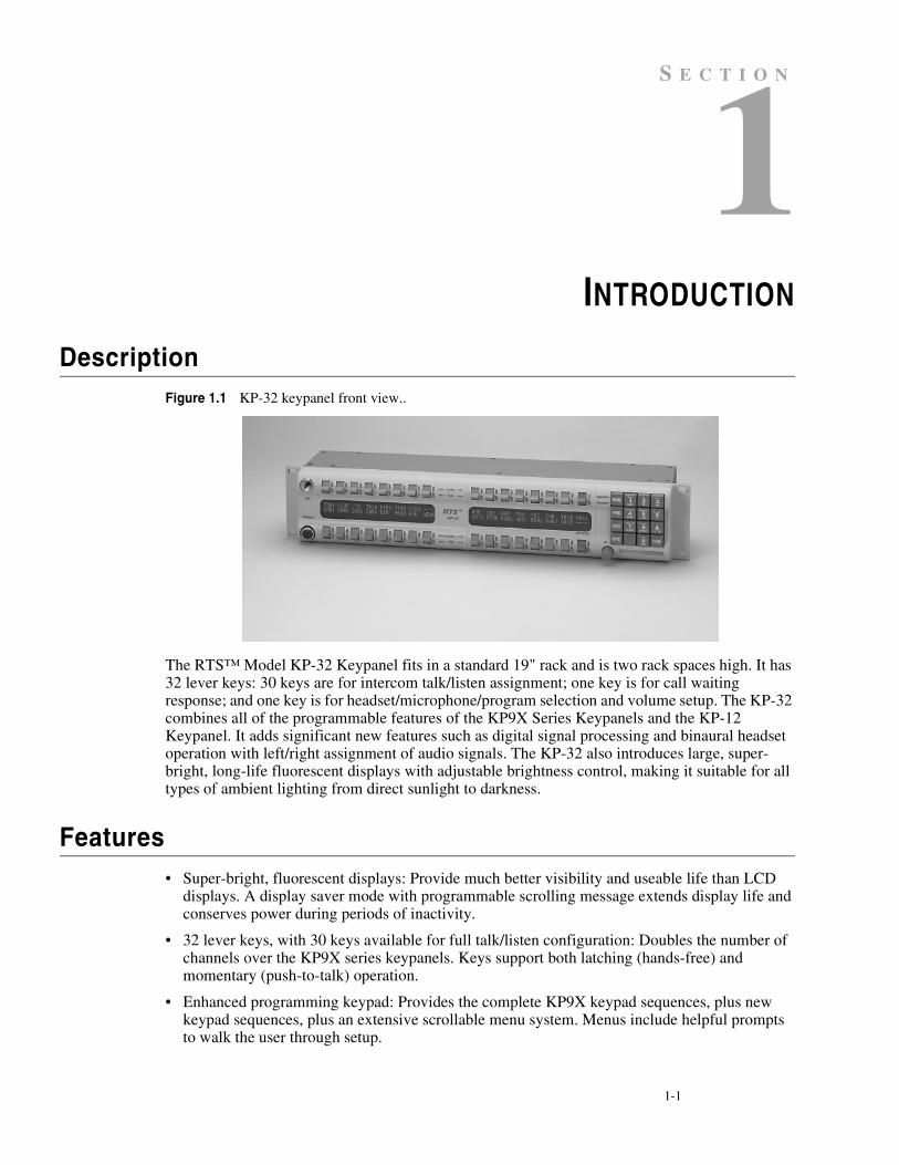
DescriptionFigure 1.1 KP-32 keypanel front view..
The RTS™ Model KP-32 Keypanel fits in a standard 19" rack and is two rack spaces high. It has 32 lever keys: 30 keys are for intercom talk/listen assignment; one key is for call waiting response; and one key is for headset/microphone/program selection and volume setup. The KP-32 combines all of the programmable features of the KP9X Series Keypanels and the KP-12 Keypanel. It adds significant new features such as digital signal processing and binaural headset operation with left/right assignment of audio signals. The KP-32 also introduces large, super-bright, long-life fluorescent displays with adjustable brightness control, making it suitable for all types of ambient lighting from direct sunlight to darkness.
Features• Super-bright, fluorescent displays: Provide much better visibility and useable life than LCD
displays. A display saver mode with programmable scrolling message extends display life and conserves power during periods of inactivity.
• 32 lever keys, with 30 keys available for full talk/listen configuration: Doubles the number of channels over the KP9X series keypanels. Keys support both latching (hands-free) and momentary (push-to-talk) operation.
• Enhanced programming keypad: Provides the complete KP9X keypad sequences, plus new keypad sequences, plus an extensive scrollable menu system. Menus include helpful prompts to walk the user through setup.
1-2 K P - 3 2 U s e r M a n u a l
• Only 90 mm deep behind the front panel (approximately 130 mm with connectors): Perfect for consoles, OB vans, etc.
• Digital Signal Processing (DSP): Improves microphone voice activation and limiting. Adds new mixing, metering, and filtering capabilities.
• Binaural (5-pin) Headset Connector: Works with the DSP mixing feature. Lets you independently assign intercom, microphone, and program audio to left or right headphone. Note: monaural (4-pin) connector available as an option. For monaural operation, the mixer lets you select which items are monitored in the headphones.
• Easy upgrades: Firmware updates can be received via the internet, for example, and then downloaded to the KP-32 via the intercom connection. Ready for future communication enhancements, including coax, fiber, and ISDN. (For further information, search for keyword "firmware" in ADAMedit help.)
Options
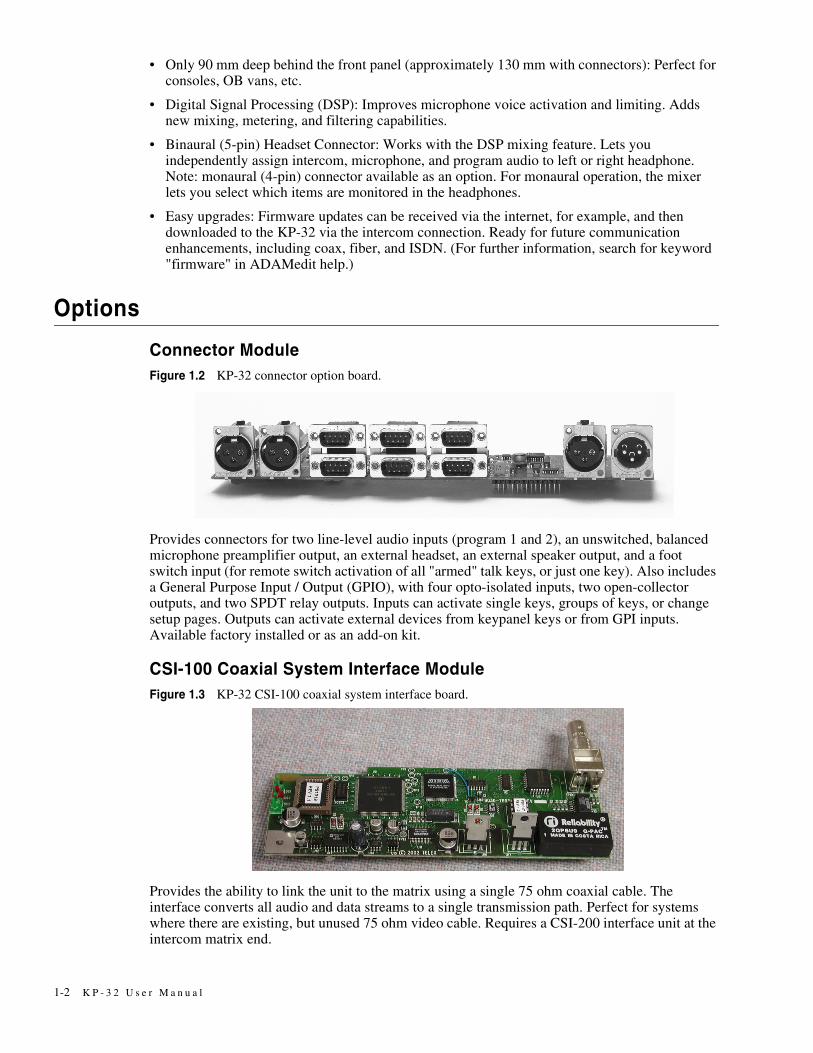
Connector ModuleFigure 1.2 KP-32 connector option board.
Provides connectors for two line-level audio inputs (program 1 and 2), an unswitched, balanced microphone preamplifier output, an external headset, an external speaker output, and a foot switch input (for remote switch activation of all "armed" talk keys, or just one key). Also includes a General Purpose Input / Output (GPIO), with four opto-isolated inputs, two open-collector outputs, and two SPDT relay outputs. Inputs can activate single keys, groups of keys, or change setup pages. Outputs can activate external devices from keypanel keys or from GPI inputs. Available factory installed or as an add-on kit.
CSI-100 Coaxial System Interface ModuleFigure 1.3 KP-32 CSI-100 coaxial system interface board.
Provides the ability to link the unit to the matrix using a single 75 ohm coaxial cable. The interface converts all audio and data streams to a single transmission path. Perfect for systems where there are existing, but unused 75 ohm video cable. Requires a CSI-200 interface unit at the intercom matrix end.
1-3
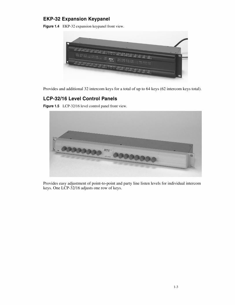
EKP-32 Expansion KeypanelFigure 1.4 EKP-32 expansion keypanel front view.
Provides and additional 32 intercom keys for a total of up to 64 keys (62 intercom keys total).
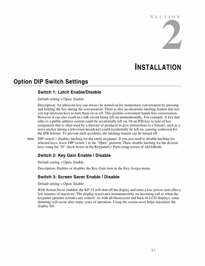
LCP-32/16 Level Control PanelsFigure 1.5 LCP-32/16 level control panel front view.
Provides easy adjustment of point-to-point and party line listen levels for individual intercom keys. One LCP-32/16 adjusts one row of keys.

1-4 K P - 3 2 U s e r M a n u a l
This Page Left Blank Intentionally
2-1
S E C T I O N
CHAPTER 2INSTALLATION
Option DIP Switch Settings
Switch 1: Latch Enable/Disable
Default setting = Open: Enable.
Description: An intercom key can always be turned on for momentary conversation by pressing and holding the key during the conversation. There is also an electronic latching feature that lets you tap intercom keys to turn them on or off. This permits convenient hands-free conversation. However it can also result in a talk circuit being left on unintentionally. For example: A key that talks to a public address system could be accidentally left on. Or an IFB key (a type of key assignment that is often used by a director or producer to give instructions to a listener, such as a news anchor during a television broadcast) could accidentally be left on, causing confusion for the IFB listener. To prevent such accidents, the latching feature can be turned off.
Note DIP switch 1 disables latching for the entire keypanel. If you just need to disable latching for selected keys, leave DIP switch 1 in the "Open" position. Then, disable latching for the desired keys using the "D" check boxes in the Keypanels / Ports setup screen of ADAMedit.
Switch 2: Key Gain Enable / Disable
Default setting = Open: Enable.
Description: Enables or disables the Key Gain item in the Key Assign menu.
Switch 3: Screen Saver Enable / Disable
Default setting = Open: Enable.
With Screen Saver enabled, the KP-32 will shut off the display and enter a low-power state after a few minutes of inactivity. The display reactivates instantaneously on incoming call or when the keypanel operator actuates any control. As with all fluorescent and back-lit LCD displays, some dimming will occur after many years of operation. Using the screen saver helps maximize the display life.
2-2 K P - 3 2 U s e r M a n u a l
Switch 4: Call Flash Timeout
Default setting = Open: 15 Second Flash.
Description: Whenever there is an incoming call and there is a talk key assigned to the caller, the talk LED next to that key will flash. The flash can be set for 15 second timeout, or until the caller's talk key is released.
Note Future versions of ADAM Edit and Zeus Edit will be able to override the Call Flash Timeout setting.
Switch 5: Footswitch Enable / Disable*
Default = Open: Disabled.
Description: The optional Connector Module has a footswitch (GRP CALL) input. If the footswitch is enabled (DIP switch 5 set to the "Closed" position), then keys that are latched on will not activate until the footswitch is closed. Latched keys are indicated by winking green talk LEDs (on time less than off time), and when the footswitch is activated, the LEDs provide the normal talk-on indication.
Notes 1 If the talk key is held down in Footswitch mode the channel will be activated until the user releases the key. The use of this function does not require the footswitch to be used.
2 If DIP switch 1 is set to the “Closed” position, nothing will latch.
3 Individual keys can be set to non-latching via ADAM Edit. If this is done, the footswitch has no effect on the keys that have been set to non-latching. Please see ADAM Edit help for more information.
Switch 6: Network Mode Selection
Default Setting: Open (Mode 1)
Description: In the Mode 1 setting, the keypanel functions operate as called out in the main portion of this manual. If the switch is closed (Mode 2), then the functions operate as outlined in this manual with slight modifications. Any function that is affected by Mode 2 operation will have an asterisk (*) by it. The changes/modifications to the functionality is called out in the section titled “Mode 2 Operation”
Switch 7: Test/Debug
Default Setting: Open.
Switch 8: Test/Debug
Default Setting: Open.
Address Switch Setting
General Information
In Zeus, ADAM CS, and ADAM Intercom Systems, intercom ports are arranged in groups of eight. All ports in a group share a common data port. Each KP-32 keypanel is uniquely identified on the data port by the setting of its Address switch. The method of determining the proper Address switch setting varies for each intercom system. Use the method for your intercom system as described below. Then set the white pointer on the Address switch to point to the correct setting.
2-3
Address Setting for Zeus
Intercom port connectors on the Zeus back panel are arranged in three groups of eight intercom ports. For each group, intercom port connectors are labeled ID 1, ID 2, etc. When you connect a KP-32 keypanel to Zeus, set the Address switch to match the corresponding ID number on the Zeus back panel. Note that address switch settings 0, and 9 through F are not used.
Address Setting for ADAM CS
Each Audio I/O card contains 1 group of 8 intercom ports. However, the method of breaking out the groups depends on the type of connectors on the back panel.
ADAM CS with RJ12 or DB-9 back panel:
The intercom port connectors are arranged in groups of 8. The first connector at the left for each group is Address 1, the next is Address 2, and so forth.
Note Address switch settings 0, and 9 through F are not used.

2-4 K P - 3 2 U s e r M a n u a l
Figure 2.1 Address number vs intercom port numbers for 8-Port Audio I/O Cards (ADAM AND ADAM CS Intercom Systems.
ADAM CS with 50-pin Telco back panel:
Determine the address setting from Figure 2.1. To use the table, locate the intercom port number to which the KP-32 will be connected. Then, read across to the "Address" column to find the Address number. Set the KP-32 Address switch to this number.
Note Settings 0, and 9 through F are not used.
2-5
Address Setting for ADAM
Each Audio I/O card contains 1 group of 8 intercom ports. Determine the address setting from Figure 2.1. To use the table, locate the intercom port number to which the KP-32 will be connected. Then, read across to the "Address" column to find the Address number. Set the KP-32 Address switch to this number. Note: settings 0, and 9 through F are not used.
Connections
EXP. AND LCP Connectors
Connect from the Exp. connector on the back of the KP-32 to the Expansion 1 connector of an optional EKP-32 Expansion Panel. Use the interconnect cable supplied with the Expansion Panel. The Expansion 2 connector on the Expansion Panel can connect to a second Expansion Panel, but no more than 64 intercom keys can be operated per intercom port.
Each LCP-32/16 adjusts the listen levels for 16 keypanel keys, and you can connect as many LCP-32 panels as required to adjust all keys on the KP-32 and on an optional EKP-32 Expansion Panel. An interconnect cable is supplied with each LCP-32. Connect the first LCP-32 to the LCP connector on the KP-32. Connect the second LCP-32 to the first LCP-32, and so forth.
Note When arranging LCP-32 panels in an equipment rack, you should put them directly above or below the keys they will be used to adjust.
Frame Connector
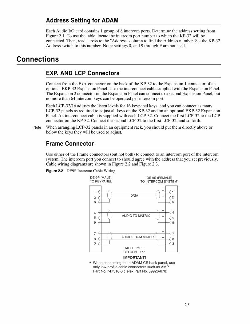
Use either of the Frame connectors (but not both) to connect to an intercom port of the intercom system. The intercom port you connect to should agree with the address that you set previously. Cable wiring diagrams are shown in Figure 2.2 and Figure 2.3.
Figure 2.2 DE9S Intercom Cable Wiring
2-6 K P - 3 2 U s e r M a n u a l
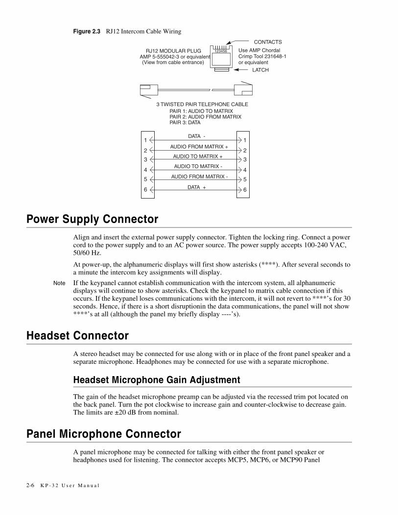
Figure 2.3 RJ12 Intercom Cable Wiring
Power Supply ConnectorAlign and insert the external power supply connector. Tighten the locking ring. Connect a power cord to the power supply and to an AC power source. The power supply accepts 100-240 VAC, 50/60 Hz.
At power-up, the alphanumeric displays will first show asterisks (****). After several seconds to a minute the intercom key assignments will display.
Note If the keypanel cannot establish communication with the intercom system, all alphanumeric displays will continue to show asterisks. Check the keypanel to matrix cable connection if this occurs. If the keypanel loses communications with the intercom, it will not revert to ****’s for 30 seconds. Hence, if there is a short disruptionin the data communications, the panel will not show ****’s at all (although the panel my briefly display ----’s).
Headset ConnectorA stereo headset may be connected for use along with or in place of the front panel speaker and a separate microphone. Headphones may be connected for use with a separate microphone.
Headset Microphone Gain Adjustment
The gain of the headset microphone preamp can be adjusted via the recessed trim pot located on the back panel. Turn the pot clockwise to increase gain and counter-clockwise to decrease gain. The limits are ±20 dB from nominal.
Panel Microphone ConnectorA panel microphone may be connected for talking with either the front panel speaker or headphones used for listening. The connector accepts MCP5, MCP6, or MCP90 Panel

2-7
Microphones. Insert the microphone and rotate the entire microphone body several turns to lock in place.
Panel Microphone Gain Adjustment
The gain of the panel microphone preamp can be adjusted via the recessed trim pot located on the back panel. Turn the pot clockwise to increase gain and counter-clockwise to decrease gain. The limits are ±20 dB from nominal.

2-8 K P - 3 2 U s e r M a n u a l
This Page Left Blank Intentionally
3-1
S E C T I O N
CHAPTER 3BASIC OPERATION
Screen Saver OperationIf the KP-32 is set for screen saver operation, the alphanumeric display automatically shuts off after several minutes of inactivity. The display reactivates on incoming call or when the keypanel operator actuates any control. DIP switch 3 turns enables/disables screen saver operation.
Note You can override the normal timeout period for screen saver operation and immediately place the keypanel in screen saver mode. See "Service Menu, Disply Dim".
Selecting Headset or SpeakerTap the Headset / Vol. Sel. key upward. The Vol. Sel. display alternates between Hdst and Spkr with each key tap. The Headset LED lights when the headset is selected and is off when the speaker is selected.
Note Future versions of ADAM Edit and Zeus Edit will be able to override the Headset or Speaker setting.
Listen Volume AdjustmentsBy default, the Vol. control adjusts the listen volume for the speaker or headset, whichever appears in the Vol. Sel. display. The level of auxiliary program inputs 1 & 2 (if GPI/O board is present and Aux inputs are enabled) and the level of incoming audio from the intercom matrix can be adjusted. To adjust a level, press the Vol. Sel. button until the desired source appears in the Vol. Sel. display (Aux1, Aux2, or Icom). Then, use the Vol. control to adjust the listen volume. The Vol. control defaults back to the speaker or headset after about one minute of inactivity of the control. The minimum volume level for either the keypanel speaker or headset may be adjusted. See “Service Menu, Min Volume”.
Note You can save the volume adjustments to be the power-up defaults using "Service Menu, Save Cfg".
3-2 K P - 3 2 U s e r M a n u a l
Intercom Keys and Displays
Alphanumeric Display Indications for Intercom Keys
Upper Case Letters: Upper case letters indicate keys that have any kind of talk assignment, with or without a corresponding listen assignment. Example: DIR1
Lower Case Letters: Lower case letters indicate keys that have only a listen assignment. Example: dir1.
Dashes ----: Dashes indicate a key that has no talk or listen assignment.
Flashing Alphanumeric Display: This means the key is activated to talk to an IFB, ISO, or TIF.
Note The flashing alphanumeric display for TIF keys, remote IFB keys, and remote ISO keys can be disabled by placing a check mark next to "Don't generate tallies for TIF and trunk use" in ADAMedit (Options menu, Intercom Configuration, Options tab).
LED Indications for Intercom Keys
Note Future versions of ADAM Edit can override LED indications.
Talk LED Indications
The talk LED is the lower LED for each key. The talk LED indications are as follows:
Continuous Green*
Talk is on and the keypanel operator can be heard at the destination.
Continuous Red Talk LED & Flashing Display Alpha ("In-use")*
The key is off, but someone is talking to the destination. This indication is provided for any local PL, IFB, ISO, or TIF key. It does not apply to remote IFB or ISO keys. This indication is provided so keypanels operators know when critical director communications are occurring. If you activate the key, either of two things will happen:
• If you activate the key and the talk LED turns continuous green, this indicates that you and the other keypanel operator are both talking to the destination.
• IFB keys only: If the talk LED flashes red when an IFB key is activated, this indicates that the other keypanel has a higher IFB priority and you cannot talk at this time.
Note The red "in-use" indication for TIF keys can be disabled in ADAMedit: In the ADAMedit Options menu, select Intercom Configuration, then click on the Options tab. Place a check mark next to "Don't generate talliesfor TIF and trunk use". Be sure to send the change to the intercom system. Note that this will also disable the flashing alpha display when talking to remote IFBs or ISOs as previously described.
Flashing Red Talk LED & Flashing Display Alternating Pattern of Alpha & (-**-) ("Busy")
You cannot talk at this time. This indication occurs when you activate a local IFB key that is already in-use by a keypanel with a higher IFB priority. It also occurs when you activate any key assigned to a remote destination, but there are currently no trunks available.
Note Flashing red is also the intended indication when attempting to talk to a remote IFB while someone else with a higher trunk IFB priority is already talking. However, this will require ADAM MC version later than 9.9.x and Trunk MC version later than 7.x.x. As of this writing, these versions are not implemented. Regardless of the indication provided, you will not be heard
3-3
at the remote location if your keypanel has the lower trunk IFB priority. IFB trunk priorities are set in ADAMedit. (Click the "KP" button on the ADAMedit toolbar to access Keypanels / Ports setup, then click the "Edit" button, then click the "Advanced" tab. Enter the desired IFB priority in the fields provided. Be sure to send the change to the intercom system.)
Flashing Green Talk LED & Display Alpha (on time equal to off time)*
There is an incoming call from the destination assigned to the key. Activate the key to talk back.
Note The duration of incoming call flash is controlled by DIP switch 4 on the KP-32 back panel. See "Option Switch Settings" for further information.
Winking Green Talk LED (on time less than off time)*This indicates that a key is ready to talk (key is on), but requires external footswitch activation to talk.
Listen LED Indication
The listen LED is the upper LED for each key. The listen LED is green when listen is on.
Intercom Key Operation
Basic Intercom Key Operation
The "up" position of an intercom key activates listen (if assigned). The "down" position activates talk (if assigned). If there is no talk assignment for an intercom key, the talk position of the key will not activate. If there is no listen assignment, the listen position will not activate.
For momentary activation of a key press and hold the key. Then, release it when finished.
For latching operation (if enabled) tap a key; it will turn on and remain on. Tap the key again to turn it off when finished.
Note Latching may be turned off for the entire keypanel by setting DIP switch 1 on the KP-32 back panel to the Closed position. Latching may be disabled for individual keys on a keypanel using ADAMedit: Click the KP button on the ADAMedit toolbar to open the Keypanels / Ports setup screen. Select the intercom port where the keypanel is connected. Place a check mark in the "D" check boxes for any keys where you want to disable latching. Be sure to send your changes to the intercom system.
Operation of Intercom Keys with Auto FunctionsNote Assignment of keys with auto functions is described in the programming sections that follow.
Descriptions of the auto functions are also contained in the Glossary.
Operation of keys with auto functions is as follows:
Talk + auto follow
Talk and listen can be activated separately. The listen assignment listens to whatever is assigned to the talk key.
Talk + auto listen
Both talk and listen will activate when talk is activated.
Talk + auto mute
Listen will turn off when talk is activated.
3-4 K P - 3 2 U s e r M a n u a l
Talk + auto reciprocal
Listen will always be on, and talk may be turned on or off.
Talk + auto table
If an IFB talk key has an auto-table listen assignment, talk and listen can be independently activated. The listen key listens to whatever is defined as the IFB Listen Source for the IFB that is assigned to the talk key.
Note A full explanation of the auto-table feature is beyond the scope of this manual. For further information, search for "IFB" in ADAMedit help, then read the topics "IFB Auto Table Description" and "IFB Setup Procedures".
All Call Key
Activating the key will also activate all keys to the left of it (up to, but not including another all-call key).
Talk + DIM
If a point-to-point key has the DIM function as a level 2 talk assignment, activating the key will cause the crosspoint levels to diminish for any other intercom ports that are currently listening to the same destination and that are in the same DIM table.
Note A full explanation of DIM tables is beyond the scope of this manual. For further information, search for "dim table" in ADAMedit help.
Operation of Intercom Keys with Options
Group Option Keys
Activating the master key in a key group will activate all keys in that group according to each key's individual key assignment. Activating a slave key will not affect any other keys in the group.
Solo Key
Activating a key that has the solo option will cause all other keys to turn off until the solo key is again turned off.
Operation of Intercom Talk Keys with the Speaker DIM Setting
Activating any talk key will cause the speaker or headphone volume at this keypanel to diminish by the amount specified in the Dim menu item on the Service menu.
Note Do not confuse this with the Talk+DIM auto function previously described. Talk+DIM affects the speaker or headphones on other keypanels when a particular talk key is activated on this keypanel. Speaker DIM affects the speaker or headphone level on this keypanel when any talk key on this keypanel is activated.
Operation of Intercom Keys assigned to TIF Ports
If an intercom key is assigned to talk to an intercom port that is designated as a TIF port in ADAMedit, placing the key in the talk position will activate the KP-32 dialing menu. See "TELEPHONE OPERATION" for further information.
Note You designate an intercom port as a TIF port by checking the "Port is TIF" check box in ADAMedit. (In ADAMedit, click the "KP" button on the toolbar to access Keypanels / Ports setup, then select the intercom port where the TIF s connected, then click the "Edit" button, then
3-5
click the "Advanced" tab. Place a check next to "Port is TIF". Remember to send the change to the intercom system.)
Muting the MicrophoneTap the MUTE key to turn microphone muting on or off.
The Vol. Sel. display alternates between Hdst and Mute (or between Spkr and Mute) while the microphone is muted.
Note While muting is on, you cannot be heard on the intercom, or by anyone on the telephone, or by any device connected to the mic preamp output of the optional connector module.
Call Waiting OperationOccasionally, a keypanel may call, and there won't be a key assigned to talk back to that caller. In this case, the caller's name will appear in the Call waiting window. Press down and hold the Call waiting key to talk back.
To clear a name from the Call waiting window, tap "up" on the Call waiting key.
If a second call is received in the Call waiting window while a caller name is already displayed, the Call waiting LED will flash red. To answer the second call, tap "up" to clear the first name, then hold the key down to talk to the second caller.
Note By default, only the names of callers who are not currently assigned to intercom keys will appear in the Call waiting window. Alternatively, you can force all caller names to display in the Call waiting window. This is controlled either by DIP switch 2 on the ADAM Master Controller card or by the ADAMedit check box titled "Always stack callers in call waiting window". (ADAMedit Options menu, Intercom Configuration, Options tab. Note: the setting in ADAMedit overrides the DIP switch 2 setting on the Master Controller card.) If your intercom system has mostly keypanels with alphanumeric displays, we recommend that you do not stack all callers in the Call waiting window.

3-6 K P - 3 2 U s e r M a n u a l
This Page Left Blank Intentionally
4-1
S E C T I O N
CHAPTER 4TELEPHONE OPERATION
Note Telephone operations require an optional TIF-951 Telephone Interface. Also, you must first assign an intercom key to talk/listen to the TIF. We recommend a talk+auto listen assignment.
Receiving A Phone CallWhen there is an incoming telephone call, the talk LED will flash red next to the KP-32 key that is assigned to the TIF. Activate the key to answer the call.
Note The red flash for incoming TIF call is the default operation. Alternatively, a continuous-red talk LED indication can be provided. This is accomplished by checking the check box "Don't generate tallies for TIF or trunk use" in ADAMedit (Options menu, Intercom Configuration, Options tab). Note that this check box also affects other tally indications. For further information, press the F1 key while viewing the ADAMedit Options tab settings. Under the topic "Don't generate tallies for TIF or trunk use" click on the "see table" link to view a table containing information about operation with and without tally indications.
DIALING AND HANGING UP USING KP9X KEYPAD SEQUENCES
KP9X Keypad Hang-up Sequence
1 Turn off the TIF talk key. (Tap "down" to toggle talk off. The talk LED should be off.)
2 On the keypad, tap PHONE CLR.
3 Momentarily turn the TIF talk key on, then off. The TIF key talk and listen indicators will turn off and the TIF-951 "OFF" LED will activate.
Note You can use the hang up sequence to hang up the TIF even if you did not place or answer the call.
KP9X Manual dial sequence
1 Activate the TIF listen key. (Tap "up" to toggle listen on. The listen LED should be on.)
2 Make sure the TIF talk key is off (Talk LED off).
3 On the keypad, tap CLR PHONE PGM.
4 Activate the TIF talk key. The talk LED turns green, the "ON" LED at the TIF-951 activates, and you should hear dial tone at the KP-32.
4-2 K P - 3 2 U s e r M a n u a l
5 Dial the telephone number. Digits scroll in the display above the TIF key.
6 When the far end answers, you can dial additional digits (to access a mail system or automated response system, etc.). When finished dialing, momentarily turn off the TIF talk key to end dialing mode (talk LED turns red).
7 Turn the TIF talk key back on for conversation.
8 To end the call:
1 Turn the TIF talk key off.
2 Tap PHONE CLR.
3 Tap the TIF talk key. The TIF key talk and listen indicators will turn off and the TIF-951 "OFF" LED will activate. The TIF-951 is now ready for another call.
KP9X Redial Sequence
Note The last dialed phone number is always stored at the TIF and over-writes any previously dialed phone number. If several people have access to the TIF, redial may not produce the results that you expect!
1 Tap the PHONE key to activate dialing mode.
2 Tap "up" on the TIF key to activate listen.
3 Tap CLR 0 0 . The last phone number will redial.
4 After the number has dialed, click the PHONE key to end dialing mode.
5 If the far end answers, tap "down" on the TIF key to activate talk.
6 Use the KP9X hang-up sequence when finished with the call.
KP9X Autodial Sequences
Note Unlike the autodial operations using the KP-32 menu system, which store telephone numbers locally within the KP-32, the KP9X autodial operations work with telephone numbers that are stored at the TIF-951. The advantage to saving at the TIF-951 is that many users can access a common set of stored telephone numbers. A disadvantage is that users can easily over-write important telephone numbers. Also, telephone numbers at the TIF-951 are stored in volatile memory and will be lost if the TIF-951 loses power.
Storing an Autodial Number in the TIF-951
1 Tap the PHONE key.
2 Tap the TIF talk key to latch it on.
3 Using the number keys on the keypad, dial the phone number that you want to store. The entire phone number sequence can have up to 30 digits.
Note To insert one or more pauses anywhere in the dialing sequence, enter CLR CLR 9 9 for each pause. A pause may be required, for example, if you need to enter a digit to get an outside line and your phone system requires a pause before continuing to dial. If you are using credit card dialing, several pauses may also be required between the phone number and your personal access code.
4 After dialing the telephone number, click CLR PGM, then enter a two-digit number (01, 02, etc. up to 32) that you will use as the autodial number.
5 After storing the autodial number, hang up using the KP9X hang-up sequence.
4-3
Dialing an Autodial Number Stored in the TIF-951
1 Tap the PHONE key to activate dialing mode.
2 Tap "down" on the TIF talk key to latch it in the on position.
3 Tap CLR followed by the autodial number (01, 02, etc.).
4 When finished dialing, click the PHONE key again to exit dialing mode.
5 Hang up using theKP9X hang-up sequence.
DIALING AND HANGING UP USING THE KP-32 DIALING MENU
The dialing menu will only activate when talking to an intercom port that has the "Port is TIF" check box activated in ADAMedit. (In ADAMedit, click the "KP" button to access the Keypanels/Ports screen, then select the port where the TIF-951 is connected, then click the "Edit" button, then click the "Advanced" tab. Place a check mark next to "Port is TIF". Remember to send this change to the intercom system.)
Manual Dialing
1 Turn on the TIF talk key. ManualDial displays in the Call waiting window.
2 Tap the PGM key. Dial#? displays, and the dial tone should be audible in your speaker or headset.
Note To hang up at any time after this point: tap the BACK key. Hang upwill display, then tap PGM.
Note While using the phone, any incoming intercom calls to the Call waiting window will go into the call waiting stack. The caller names will not be displayed, but the Call waiting LED will flash red. You may either hang up the phone and answer the intercom call, or continue with the phone call and answer the intercom call afterward.
3 Dial the phone number. Digits appear in the Call waiting window as you dial. Dialing tones are audible in the speaker or headset.
4 If the far end answers, begin your conversation.
Note After the far end answers, you may dial additional digits (to retrieve voice mail, log onto an automated answering system, etc.).
5 If there is no answer, or to hang up when finished talking, tap the BACK key. Hang up displays. Tap PGM to hang up.
Note Occasionally, you may receive intercom caller names in the Call waiting window while you are talking on the phone. In this case, the dialing menu options will be cleared from the Call waiting window, and the Hang up option won't be available. Instead of trying to reenter the menu system, use the "KP9X Keypad Hang-up Sequence".
Redial
Turn on the TIF talk key. ManualDial displays in the Call waiting window.
Tap the ↓↓ key until Redial displays.
Tap PGM.
If the far end answers, begin your conversation.
4-4 K P - 3 2 U s e r M a n u a l
Note After the far end answers, you may dial additional digits (to retrieve voice mail, log onto an automated answering system, etc.).
5 If there is no answer, or to hang up when finished talking, tap the BACK key. Hang up displays. Tap PGM to hang up.
Note Occasionally, you may receive intercom an intercom caller name in the Call waiting window while you are talking on the phone. In this case, the dialing menu options will be cleared from the Call waiting window, and the Hang up option won't be available. Instead of trying to reenter the menu system, use the "KP9X Keypad Hang-up Sequence".
Autodial
Note Autodial is only available after you have saved autodial numbers.
1 Turn on the TIF talk key. ManualDial displays in the Call waiting window.
2 Tap the ↓↓ key until Auto Dial displays.
3 Tap PGM.
4 Tap ↓↓ to select the desired autodial number, then tap PGM.
5 If the far end answers, begin your conversation.
Note After the far end answers, you may dial additional digits (to retrieve voice mail, log onto an automated answering system, etc.).
6 If there is no answer, or to hang up when finished talking, tap the BACK key. Hang up displays. Tap PGM to hang up.
Note Occasionally, you may receive an intercom caller name in the Call waiting window while you are talking on the phone. In this case, the dialing menu options will be cleared from the Call waiting window, and the Hang up option won't be available. Instead of trying to reenter the menu system, use the "KP9X Keypad Hang-up Sequence".
5-1
S E C T I O N
CHAPTER 5KP9X SERIES KEYPAD PROGRAMMING
Note A summary of the keypad programming sequences is located at the back of the manual for quick reference.
KEYPAD PROGRAMMING, DISPLAY REQUESTSDisplay requests let you view information about the keypanel configuration. You can display information by two methods: either by entering sequences on the programming keypad, or by scrolling the names of display requests in the Call waiting window and then selecting the desired display request. The scrolling method also gives you access to additional features that are not available with the keypad sequences. The following paragraphs discuss these two methods.
Display Requests Using Keypad Sequences
All display request sequences start with FUNC DISPLAY.
Display Panel ID
FUNC DISPLAY 1 .
This sequence displays the calculated port number. The calculation is based on the data group that the keypanel is connected to, combined with the Address switch setting on the back of the keypanel. Note that if the Address switch is incorrectly set, the wrong Panel ID will display.
Note For futher information about port address calculation, see the "Port" description in the Glossary.
Tap CLR to quit.
Display Level 2 Talk Key Assignments
FUNC DISPLAY 2 .
This sequence displays all level 2 talk key assignments for about 10 seconds. Lev2 displays in the Call waiting window.
Tap CLR to quit.
Display Listen Key Assignments
FUNC DISPLAY 3 .

5-2 K P - 3 2 U s e r M a n u a l
This sequence displays all listen key assignments for about 10 seconds. Lstn displays in the Call waiting window.
Tap CLR to quit.
Display Setup Page Assignments
FUNC DISPLAY E-PNL
Currently, there are four setup pages available for each keypanel. Each setup page defines a set of 16 talk and listen key assignments. Most RTS keypanels have a maximum of 16 keys, so one setup page is typically assigned to the main keypanel, and is referred to as the "Main" setup page. Additional setup pages are assigned to any connected expansion panels, and are referred to as "Expansion 1", "Expansion 2", etc.). Since the KP-32 requires 2 setup pages, it uses the main page assignments and also one expansion page (Figure 5.1). The EKP-32 uses two additional expansion pages.
Figure 5.1 Setup page usage for the KP-32 and EKP-32
When you enter the sequence FUNC DISPLAY E-PNL, the Call waiting window displays Mn-1 or Mn-2, etc. This indicates which setup page is currently being used at the "Main" position. After a few moments X1-1, or X1-2, etc. displays. This indicates which setup page is currently being used by expansion 1. Next, if there is an expansion panel connected, X2-1 or X2-2 etc. displays, followed by X3-1 or X3-2 etc. to indicate the setup page usage for expansion 2 and expansion 3.
Tap CLR to quit.
Note To change the setup page assignments, see "KEYPAD PROGRAMMING, ASSIGNING SETUP PAGES".
Test Keys and Displays
FUNC DISPLAY 0
When you enter this sequence, all alpha-numeric displays show a % symbol. Pressing down on any key (except the Headset / Vol. Sel. key) will cause OK to display. This verifies operation of the key. Tapping up or down on the Headset / Vol. Sel. key will cause the display to cycle through the available selections.
If latching is enabled, tapping up or down on any intercom key, or the Call waiting key, will cause the corresponding red LED to light. This verifies latching operation and also that the each red LED is OK.
Holding any key in the up or down position will cause the corresponding green LED to light. This verifies operation of the green LEDs.
Tap CLR to quit.
Note This sequence is similar to Service Menu, Test Panel, page 44, except that the service menu test also lets you check the operation of the keypad buttons.
5-3
Tone Generator Activation (FUNC-DISPLAY-7)
FUNC DISPLAY 7
This sequence activates the keypanel's internal tone generator. You can use the tone generator to check the audio send and receive paths to and from the matrix. For example, you can assign a talk key on the keypanel to talk to itself. When you activate the talk key, you should be able to hear the tone from the keypanel speaker or from a headset.
To turn off the tone generator, press the CLR key.
Note The microphone input is turned off when the tone generator is active.
Display Requests Using Scrolling
The display requests described previously can also be accessed using scrolling. Scrolling also offers several additional features. To use scrolling, tap FUNC DISPLAY followed by ↓↓ or −− to scroll through the list of display requests. The display request names will appear in the Call waiting window as follows:
ID PGM: Displays the calculated port number. CLR to quit.
Lev2 PGM: Displays level 2 talk assignments. CLR to quit.
Lstn PGM: Displays listen assignments. CLR to quit.
Name PGM: Displays crosspoints closed to this keypanel. CLR to quit.
Type PGM: Displays level 1 talk key assignment types. CLR to quit.
Mtx PGM: Displays matrix ID for all level 1 talk assignments. CLR to quit.
Tone PGM: Turns on tone generator. CLR to quit and turn off tone generator.
Epnl PGM: Displays setup page assignments. Mn=KP-32 bottom row keys. X1=KP-32 top row key. X2=EKP-32 bottom row keys. X3=EKP-32 top row keys.
Gain PGM: After selecting this item, tap up on any listen key with a point-to-point or party line assignment. The current listen gain from this keypanel to the intercom port or party line displays in the Call waiting window. Tap ↓↓ or − − to change the gain. CLR to quit. Use VRst PGM to reset all gains.
VRst PGM: Reset all port / party line gains to 0dB.
Asgn PGM: Displays a list of key assignments that are set up for this keypanel, but not currently accessible. This includes talk level 1 assignments on setup pages that are not currently assigned, and any key assignment that might be obscured by the call-waiting window. You can scroll through the list using the ↓↓ − − keys. Then use the Call waiting key to talk to any of the listed destinations.
Test PGM: Test keys and displays. CLR to quit.
Vxxx: Display keypanel firmware version. CLR to quit.
KEYPAD PROGRAMMING, ASSIGNING SETUP PAGES1 Tap the E-PNL key.
2 Select one of the four setup pages: tap 1 , or 2 , etc.
3 Tap the PGM key.
4 Tap any key in the row of keys where you want to assign the setup page.
5-4 K P - 3 2 U s e r M a n u a l
Notes • The same setup page cannot be assigned in more than one place. If a setup page is already assigned somewhere else, you must clear or change that assignment first. With the exception of the main row assignment, you can clear any page assignment from a row of keys by entering E-PNL 0 PGM, then pressing any key in the row.
• If you cannot change the setup page assignments for a particular keypanel, this feature may be restricted in ADAMedit (Keypanels / Ports screen, Edit button, Setup tab, Setup Page Options).
• To display setup page assignments at any time, see "Display Setup Page Assignments".
KEYPAD PROGRAMMING, ASSIGNING INTERCOM KEYS
General
There are three methods to assign intercom keys with keypad programming. These methods are summarized below and explained on the following pages.
• Key Assignment using Keypad Numeric Entry: Using this method, you enter the panel number, party line number etc. that you wish to assign to a key. This method requires that you know the number (not the name) of the port, party line etc. that you wish to assign. Since most users do not have access to this information, this method of key assignment is not recommended.
• Key Assignment by Copying an Assignment: Using this method, you can copy an assignment from one key to another. You can also use this method to transfer an incoming call to a talk key and/or listen key.
• Key Assignment using Alpha Scrolling: Using this method, you scroll through lists of alpha names in the Call waiting window and select the name of the panel, party line etc. that you want to assign. Then you copy that name to a key. If descriptive names have been assigned (using the intercom system configuration software) alpha scrolling is easiest to use.
Assigning Keys Using Keypad Numeric Entry
Note Each programming step must be completed within 4-5 seconds. Otherwise, the programming sequence will automatically quit.
General Procedure
1 For talk level 2 assignment only: Tap 0 0 . Otherwise, skip this step.
2 Select the key assignment type:
NUM Intercom port.
PL Party line.
AUTO Auto function.
FUNC SLIST Special list.
FUNC IFB IFB
FUNC ISO Camera ISO
FUNC RELAY Relay or GPI output.
3 Auto function assignment only: Tap an additional number to select the desired auto function:
1 Auto listen (listen keys only)
2 Auto follow (listen keys only)
5-5
3 Auto mute (listen keys only)
4 Auto reciprocal (listen keys only)
5 All call (talk level 1 only)
6 DIM (talk level 2 only, for point-to-point key, must enter 00 first)
7 Auto table (listen only, when talk level 1 is an IFB assignment)
4 Trunked intercoms only: (Skip when assigning auto functions or local key assignments.) Select an intercom matrix (tap 1 , or 2 etc.).
Note Intercom system numbers are the numbers that appear in the "Icm" column in CStrunk when you select "Names" or "Setup" from the Intercoms menu.
5 (Skip when assigning auto functions.) Tap one or more number keys to select the desired port number, party line number, etc:
1 If the destination is in the local matrix, just enter the number.
2 If the destination is in a remote matrix, you must always enter exactly 3 digits for a port number, or exactly 2 digits for anything else. For example, to assign port 1 you must enter 0 0 1 ; for party line 1 you must enter 0 1 .
6 Tap PGM.
7 Tap down on a key to assign talk. Tap up to assign listen.
Notes • If a key will not accept an assignment, the destination that you are trying to assign may not be scrolling enabled in ADAMedit. Or, the key that you are trying to assign may be restricted in ADAMedit.
• Auto functions are always assigned in the local intercom system, even when used with keys assigned to a remote intercom system. For example, you can program a talk key to talk to a remote party line and then program the listen key using auto-listen on the local intercom. Pressing the talk key automatically activates listening for the remote party line.
Programming Key Assignments Using Copy
There are two ways to copy key assignments: 1) you can copy a call from the Call waiting window to a key; or 2) you can copy one key's assignment to another key.
Copying a Call from the Call waiting Window to a Key
1 While the caller's name is displayed in the Call waiting window, tap the COPY CW key.
2 Tap the key where you want to copy to. The name of the caller should appear in the display above the key.
Note If a key will not accept an assignment, the destination that you are trying to assign may not have scrolling enabled in ADAMedit. Or, the key that you are trying to assign may be restricted in ADAMedit.
Copying One Key Assignment to Another Key
1 Tap the FUNC key.
2 Tap the EX COPY key.
3 Press the talk or listen key from which you wish to copy.
4 Press the talk or listen key to which you wish to copy. The name of the key assignment should appear in the display above the key.
5-6 K P - 3 2 U s e r M a n u a l
Note If a key will not accept an assignment, the destination that you are trying to assign may not have scrolling enabled in ADAMedit. Or, the key that you are trying to assign may be restricted in ADAMedit.
Programming Key Assignments Using Alpha Scrolling
Alpha scrolling lets you scroll through a list of names of ports, party lines etc. in the Call waiting window. Once the desired name is displayed in the window, you can copy it to a key. There are four scrolling modes: intercom, type, prefix and single-step. The following example demonstrates their use.
Example: Assign a port to a key using the various scrolling modes.
1 If the port is located in a remote intercom system, tap FUNC −− or FUNC ↓↓ to enter intercom scroll mode and scroll up or down the list of intercoms in the Call waiting window. Otherwise, skip to step 2.
2 When the desired intercom system name is displayed, or when making an assignment in the local intercom system, tap FUNC TYPE to activate type scroll mode.
3 Use the −− or ↓↓ keys to locate the desired type of communication. In this example, you would scroll to "P-P".
Abbreviations for types of communication:
• P-P: Point-to-Point
• PL: Party Line
• IFB: IFB
• SPCL: Special List
• RLY: Relay or GPI output.
• ISO: ISO
4 When the desired type of communication is displayed, press PGM to retrieve the requested list. Pressing PGM also exits type scroll mode and places the keypanel in single-step scroll mode.
Note In some cases, "WAIT" may display briefly while the requested list is being retrieved. "N/A" may display if there is no list. In this case, scrolling is disabled in ADAMedit for all destinations of the selected type. For further information about scroll settings, search for keyword "scroll" in ADAMedit help.
5 When the keypanel is in single-step scroll mode it may take a long time to scroll to the desired name (this is particularly true of point-to-point lists). To speed up the process, you can use prefix scroll mode. Prefix scrolling mode scrolls through a list in alpha-numeric order, but displays only the first occurrence of each two-character prefix. For example, if your intercom system had users CAM1, CAM2, CAM3, DIR1, DIR2; prefix scrolling would display CAM1 followed by DIR1. Once you locate a desired two-character prefix using prefix scroll, you can switch back to single-step scrolling to make your final selection. Tap PREFIX to enter prefix scroll mode, then use the −− ↓↓ keys to scroll. When you locate a name with the same first two characters as the name you are looking for, tap the PGM key to return to single-step scrolling mode.
6 In single-step mode, use the −− ↓↓ keys to make your final intercom port selection.
Note If you cannot locate the destination that you are looking for, it may not have scrolling enabled in ADAMedit.
7 Copy the selected port to a talk or listen key:
1 Tap COPY
5-7
2 Tap down on an intercom key to assign talk, or tap up to assign listen.
Clearing a Key Assignment
There are two ways to clear a key assignment:
Method 1: Clearing the Call waiting Window and Copying it to a Key
1 Clear the Call waiting window, if necessary, by tapping up one or more times on the Call waiting key.
2 Tap the COPY CW key.
3 Tap the key that you want to clear. Tap up to clear listen, down to clear talk.
Note If a key will not clear, it is probably restricted using the "R" check box in ADAMedit.
Method 2: Copying a Blank Key Assignment to the Key that You want to Clear
1 Tap the FUNC key.
2 Tap the EX COPY key.
3 Tap an unassigned key.
4 Tap the key that you want to clear. Tap up to clear listen, down to clear talk.
Note If a key will not clear, it is probably restricted using the "R" check box in ADAMedit.

5-8 K P - 3 2 U s e r M a n u a l
This Page Left Blank Intentionally
6-1
S E C T I O N
CHAPTER 6KP-32 MENU SYSTEM
Note A chart of the menu system is located at the back of the manual for quick reference.
MENU SYSTEM, MENU ACCESS1 Clear all names from the Call waiting display (if not clear) by tapping "up" one or more times
on the Call waiting key.
2 Tap MENU to activate the menu system.
3 Press ↓↓ to scroll forward through the list of menus. Press − − to scroll back.
4 Tap FWD or PGM to enter a menu. Tap BACK to exit a menu.
5 Within a menu:
• Press ↓↓ or − − to scroll.
• Tap FWD or PGM to select an item.
• Tap BACK to cancel a selection or to go back to the previous menu level.
MENU SYSTEM, DISPLAY MENUUse this menu to display information about the keypanel configuration.
Display Menu, Asgn Type
Displays the talk level 1 assignment types for all keys. Abbreviations for the key assignment types appear in the alphanumeric displays as follows:
• P-P: Point-to-point talk key.
• PL: Party line talk key.
• IFB: IFB talk key.
• SPCL: Special list talk key.
• RLY (System relay): The key activates a GPI output at the intercom frame, or a relay output at a UIO-256 or FR9528 frame.
• ISO: Camera ISO talk key.
• UPL: UPL resource key.
6-2 K P - 3 2 U s e r M a n u a l
• AC: All-call key.
Note For descriptions of the various key assignment types, see the "GLOSSARY".
Display Menu, Chans On
Displays an alpha list, in the Call waiting window, of all intercom ports that currently have talk crosspoints closed to this keypanel. Chans On is typically used to locate an open mic or other open audio source that needs to be shut off. The most likely cause is typically a talk key that has been left on at some keypanel. In this case, use the ↓↓ and − − keys to scroll through the list of names. You can then press the Call waiting key to ask the person at the other end to turn off their talk key.
Display Menu, Key Groups
Use the ↓↓ or − − key to select Group 1, Group 2, etc. Then press FWD or PGM to display the group. The talk and listen LEDs of the master key will be lit red and the talk and listen LEDs for the slave keys will be lit green.
Display Menu, Key List
Displays and allows access to all the other assignments on the other keypanel pages that are not currently showing in the keypanel display.
Display Menu, Level 2
Displays the talk level 2 assignments for all keys.
Display Menu, Listen
Displays the listen assignments for all keys.
Display Menu, Matrix
Displays the intercom system name for all talk level 1 key assignments. In non-trunked intercom systems, the intercom system name is always LOCL (local). In trunked intercom systems, intercom system names are created in CStrunk (Intercoms menu, Names.)
Display Menu, Panel ID
Panel ID displays the calculated port number that the keypanel is connected to. The calculation is based on the data group that the keypanel is connected to, along with the Address switch setting on the keypanel. If the Address switch is incorrectly set, the wrong Panel ID will display. Panel ID also displays the port alpha in brackets if the port is not scroll restricted.
Display Menu, Version
Displays the firmware version of the keypanel.
Note For firmware upgrades, contact your intercom system dealer. The KP-32 firmware can be upgraded from ADAMedit. In ADAMedit Help, search for "firmware update".
6-3
MENU SYSTEM, KEY ASSIGN MENUUse this menu to assign intercom keys, to adjust listen levels for point-to-point keys and party line keys, and to assign setup pages.
General Procedure to use the Key Assign Menu
1 Clear the Call waiting window if necessary, by tapping upward one or more time on the Call waiting key.
2 Tap Menu
3 Tap ↓↓ to scroll down to the Key Assign menu.
4 Tap PGM or FWD to enter the menu.
Note If you do not have a trunking intercom system, skip to step 6.
5 Remote key assignment only (trunking systems only): If your intercom system is configured for trunking, Matrix displays in the Call waiting window. You must select a remote intercom matrix before assigning intercom keys to destinations in that matrix. You do not need to select an intercom matrix if you are assigning keys in your own intercom system. Also, do not select an intercom matrix if you are assigning auto functions or setup pages, or if you are changing listen gains for remote point-to-point keys or remote party line keys. Select a matrix as follows:
1 Press FWD or PGM to access the Matrix list.
2 Press ¯¯ o r -- , to locate the desired matrix.
3 Press FWD or PGM to select a matrix. Wait may display while the scroll lists for that matrix are loading.
6 Pt-to-Pt should now display in the Call waiting window (both for local and remote key assignment). This is the list of available point-to-point key assignments. Press ↓↓ or −− to select a different list as follows:
Pt-to-Pt: Assign a key to talk/listen to another intercom port.
Party Line: Assign a key to talk/listen to a party line.
IFB: Assign a key to talk/listen to an IFB.
Spcl List: Assign a key to talk/listen to a special list.
Sys Relay: Assign a key to activate a relay or GPI output.
Camera ISO: Assign a key to talk/listen to an ISO.
UPL Resrc: Assign a key to activate a UPL resource.
Auto Func: Assign an auto function to a key. (If you select this item, skip the rest of this procedure and go to "Key Assign Menu, Auto Func".)
Key Gain: Adjust the listen gain for a key that already has a point-to-point or party line assignment. (If you select this item, skip the rest of this procedure and go to "Key Assign Menu, Key Gain".)
Reset Vols: Restore the default listen level for keys that have a point-to-point or party line assignment. (If you select this item, skip the rest of this procedure and go to "Key Assign Menu, Reset Vols".)
Setup Page: Change the setup page assignments. (If you select this item, skip the rest of this procedure and go to "Key Assign Menu, Setup Page".)
7 Tap PGM or FWD to select a list. In some cases Wait may display while the requested list is uploaded from the intercom system.
6-4 K P - 3 2 U s e r M a n u a l
8 When the requested list is displayed, press ↓↓ or −− , to locate the desired assignment.
9 Tap PGM or FWD to select the assignment.
10Talk Lvl 1 should now display in the Call waiting window. Press ↓↓ or −− if necessary to select a different option. Options are as follows:
• Talk Lvl 1: Assigns only talk level 1. Leaves the listen assignment as is.
• Listen: Assigns only listen. Leaves the talk assignment as is.
• Talk + AF: Assigns talk level 1, with auto-follow listen.
• Talk + AL: Assigns talk level 1, with auto-listen.
• Talk + AM: Assigns talk level 1, with auto-mute listen.
• Talk + AR: Assigns talk level 1, with auto-reciprocal listen.
• Talk Lvl 2: Assigns talk level 2.
If you attempt to assign talk level 2 to a key and there is no talk level 1 assignment, your assignment will go on talk level 1.
11If you change the talk level 1 assignment for a key that also has a talk level 2 assignment, the talk level 2 assignment will be erased.
12Tap PGM or FWD to select one of the previously listed items.
13Tap Key should now display.
14Tap an available intercom key. Tap down for any kind of talk key assignment. Tap up for a listen-only key assignment.
• If you assign any type of talk key, the assignment name will appear in the alphanumeric display above the key.
• If you add a listen assignment to an existing talk assignment, the listen assignment will appear briefly in the alphanumeric display to confirm the assignment. Then the talk assignment will reappear.
• If you assign a key that is listen only, the assignment name will appear briefly in upper-case letters, then will change to lower-case letters.
This completes the key assignment procedure. Refer to any notes below regarding the various key assignment types.
Note When reassigning keys remember to remove any Chime, Solo, or Key Group options if they will not be needed for the new key assignment.
Key Assign Menu, Matrix
Matrix appears only for trunked intercom systems. You must select a remote intercom matrix before assigning intercom keys to destinations in that matrix. You do not need to select matrix to assign keys to destinations in your own matrix. You also do not need to select a matrix when assigning an auto function to a key.
Key Assign Menu, Pt-to-Pt
Assigns a key that talks or listens to another intercom port. Note that some pt-to-pt destinations may be non-keypanel devices that cannot activate talk and listen paths. Therefore, if you want full communication, you may need to assign both talk and listen on the key.
6-5
Key Assign Menu, Party Line
Assigns a key that talks and/or listens to a party line. The key will have no effect until members have been assigned to the party line in ADAMedit. Note that party lines members are usually non-keypanel devices that cannot activate talk and listen paths. Therefore, if you want full communication with the party line, you will need to assign both talk and listen on the key. If all communications will normally be 2-way, you may wish to assign the key as Talk + auto listen.
Key Assign Menu, IFB
By default, all IFBs are restricted and you will see Not Availwhen you attempt to select this item. To see IFBs you must check the appropriate Scroll Enable check boxes in ADAMedit.
Key Assign Menu, Spcl List
Assigns a key that talks and/or listens to a special list. The key will have no effect until members have been assigned to the special list in ADAMedit. Note that some or all special list members may be non-keypanel devices that cannot themselves activate talk and listen paths. Therefore, if you want full communication with all members of the special list, you may need to assign both talk and listen on the key.
Key Assign Menu, Sys Relay
Sys Relay refers to any of several types of control devices that can exist in the intercom system, including:
• The 8 GPI outputs from an ADAM Frame (J11 on the XCP-ADAM-MC Breakout Panel).
• The 8 GPI outputs of an ADAM CS frame (J903 on the ADAM CS back panel).
• The relay outputs of an FR9528 Relay Frame (RELAY OUTPUTS connector on the FR9528 back panel).
• The 16 GPI outputs of a UIO-256 Universal Input/Output Frame (J5 on the UIO-256 back panel).
Key Assign Menu, Camera ISO
By default, all ISOs are restricted and you will see Not Avail when you attempt to select this item. To see ISOs you must check the appropriate Scroll Enable check boxes in ADAMedit.
Key Assign Menu, UPL Resrc
By default, all UPL resources are restricted and you will see Not Avail when you attempt to select this item. To see UPL resources you must check the appropriate Scroll Enable check boxes in ADAMedit. (In the ADAMedit System menu, select UPL Resources. Then enter check marks in the appropriate Scroll Enable boxes.)
Key Assign Menu, Auto Func
1 Press FWD or PGM to select auto functions in the Key Assign menu. Then press ↓↓ o r −− to locate the desired auto function as follows:
• AutoFollow (AF, for listen keys only)
• Auto Listn (AL, for listen keys only)
6-6 K P - 3 2 U s e r M a n u a l
• Auto Mute (AM, for listen keys only)
• Auto Recip (AR, for listen keys only)
• All Call (AC, for talk level 1 only)
• Dim ( Dim Table function, for talk level 2 on point-to-point keys only)
2 Press FWD or PGM to select the desired auto function.
3 Tap Key displays. Tap an intercom key to assign the selected auto function. Tap up to assign all auto functions except All Call or DIM. Tap down for All Call or DIM.
Notes • If the assignment is successful, the abbreviation for the auto function will appear in the alphanumeric display for that key. However, if you try to assign an auto function to a key that already has that auto function assigned, the assignment will be ignored. The assignment will also be ignored if scroll enable for auto functions has been disabled in ADAMedit, or if the key you are trying to assign has been restricted in ADAMedit.
• You can tap CLR to exit and return to normal operation, or tap BACK to return to the auto function menu and make more assignments.
• Trunked intercom systems: Do not select a matrix before assigning auto functions. All auto functions are assigned using the local matrix menus.
• You do not need to run Save Cfg to store auto function assignments. These are stored in the intercom system.
• For descriptions of the auto functions, see "GLOSSARY".
Key Assign Menu, Key Gain
Use this menu item to adjust the listen gains for point-to-point or party line keys. The key that you want to adjust must already have a point-to-point or party line listen assignment.
1 Press FWD or PGM to select Key Gain in the Key Assign menu.
2 Tap Key displays. Tap "up" on the key that you want to adjust.
3 The current listen level displays in the Call waiting window.
4 Press ↓↓ o r −− to change the listen level.
5 You may tap additional point-to-point or party line keys to change their listen levels. Or, tap CLR to quit.
Note You do not need to run Save Cfg to store key gain changes. These are stored in the intercom system.
Key Assign Menu, Reset Vols
Use this menu item to simultaneously reset gains for all point-to-point or party line keys.
1 Press FWD or PGM to select Reset Vols in the Key Assign menu.
2 Done displays. All key gains are now reset to the default level.
3 Tap CLR to quit.
Note You do not need to run Save Cfg after resetting key gains. These settings are stored in the intercom system.
6-7
Key Assign Menu, Setup Page
Use this menu item to change the setup page assignments on the KP-32 or EKP-32. One setup page is used for the top row of keys, and another setup page is used for the bottom row.
1 Press FWD or PGM to select Setup Page in the Key Assign menu.
2 Page 1 displays.
3 Press ↓↓ o r −− to select any of the following:
Page 1: Assign setup page 1 to the KP-32 or EKP-32.
Page 2: Assign setup page 2 to the KP-32 or EKP-32.
Page 3: Assign setup page 3 to the KP-32 or EKP-32.
Page 4: Assign setup page 4 to the KP-32 or EKP-32.
Clear Page: Clear a page assignment from the KP-32 or EKP-32.
4 Tap PGM.
5 Tap Key displays. Tap any key in the row where you want to assign the setup page. The key assignments for that page should appear in the displays.
6 You can press ↓↓ o r −− to select and assign another setup page. Or, tap CLR to exit.
Note You do not need to run Save Cfg to store changes to setup pages. These are stored in the intercom system.
KEY OPTION MENU
Key Option Menu, Auto Dial
Use this menu item to store auto dial numbers.
1 Select Auto Dial, then tap PGM.
2 Phone#? displays.
3 Begin tapping number keys. The numbers will scroll in the Call waiting window.
Note To insert a pause at any time, tap CLR 9 9 . For example, you may have to insert a pause after dialing 9 to get an outside line.
4 Tap FWD. (Do not tap PGM!)
5 A-Dial #1 displays (store auto dial number 1). To store a different auto dial number, press ↓↓ or − − to select the desired auto dial number.
6 Tap PGM.
7 #XX saved displays (where XX = the auto dial number you selected).
8 Run Service Menu, Save Cfg, to store auto dial numbers.
Key Option Menu, Chime
You can add a chime tone to any key for incoming call announcement. The chime tone will activate for about 5 seconds after a call is received.
1 Select Chime, then tap PGM.
6-8 K P - 3 2 U s e r M a n u a l
2 Tap any keys where you want to add a chime tone. Both LEDs will light red for the selected keys.
3 Tap CLR to exit.
4 Run Service Menu, Save Cfg, to store Chime settings.
Note The chime option will continue on a key even if you change the key assignment.
Removing the chime option from a key
Repeat the procedure to add chime, but tap any keys where the LEDs are lit red to turn them off. Run Save Cfg to store the changes.
Key Option Menu, Key Groups
You can set up a key group, so that when you activate one key (the master key) all keys in the group will activate. Up to 4 key groups can be set up.
1 Select Key Groups, then tap PGM.
2 Group 1 displays. To select a different group, press ↓↓ or − − .
3 Tap PGM.
4 Tap Master displays. The master key is the key that you will press to activate the group.
5 Tap the intercom key that you want to use as the master. Both LEDs next to the key will light red.
6 After you select the master key, Tap Slaves displays. Slave keys are the keys that will activate along with the master key.
7 Tap one or more keys to select them as slave keys. Both LEDs will light green for each key that is selected. You can tap a key again to remove it from the key group.
8 Tap CLR when finished.
9 Activating the master key should now cause it and all slave keys to activate. The LEDs for each key will activate according to the current key assignment for that key.
10Run Service Menu, Save Cfg, to store Key Group settings.
Note Key group settings will continue on keys even if you change the key assignments.
Clearing a key group
1 Select Key Groups, then tap PGM.
2 Group 1 displays. To select a different group, press ↓↓ or −− .
3 Tap PGM.
4 Tap Master displays.
5 Tap the current master key. The LEDs will remain lit red.
6 After you tap the master key, Tap Slaves displays.
7 Tap all the keys where the LEDs are lit green. This will turn the LEDs off.
8 Tap CLR when finished.
9 The key group is now cleared.
10Run Service Menu, Save Cfg, to store the cleared key group setting.
6-9
Key Option Menu, Solo
A solo key will cause all other keys to turn off when activated. You can assign one solo key.
1 Select Solo then tap PGM.
2 Tap Key displays.
3 Tap a key. Both LEDs for the key will light red to confirm the assignment. Tap the key again if you made a mistake and want to remove the assignment.
4 Tap CLR when finished.
5 Activating the solo key should now cause all other activated keys to turn off. The keys will turn back on again when you turn off the solo key.
6 Run Service Menu, Save Cfg, to store the Solo setting.
Note The solo option will continue on a key even if you change the key assignment.
Removing the solo key option
1 Select Solo, then tap PGM.
2 The LEDs for the solo key will be lit red.
3 Tap the solo key to turn off the LEDs.
4 Tap CLR to exit.
5 The solo key is now cleared.
6 Run Service Menu, Save Cfg, to save the change.
SERVICE MENU
Service Menu, Aux Inputs
Enables or disables an AUX input audio path to any outputs.
1 Select Aux Inputs, then tap PGM.
2 Aux In 1 displays. To select Aux In 1 or 2, press ↓↓ .
3 Tap PGM.
4 →Enabled displays.To select enabled or disabled, press ↓↓. The arrow indicates that the input is enabled.
5 Tap PGM
6 Tap CLR to exit when finished
7 The new Aux In assignment is now set.
8 Run Service Menu, Save Cfg, to store the Aux Inputs setting.
9 To assign the destination of the Aux Inputs, see the Mixing entry for “Service Menu, DSP Func”.
Service Menu, Dim
This item causes the speaker or headphone level to diminish by a specified amount whenever a talk key is activated.
6-10 K P - 3 2 U s e r M a n u a l
1 Select Dim, then tap PGM.
2 Speaker displays. To select headset, press ↓↓ .
3 Tap PGM.
4 By default, -8dB displays for speaker, and 0dB displays for headset. This is the default amount of dimming.
5 Press ↓↓ to increase the amount of dimming. Press −− .to decrease it.
6 Tap CLR to exit when finished.
7 The new dimming level is now set.
8 Run Service Menu, Save Cfg, to store the Dim setting.
Service Menu, Disply Dim
This item adjusts the alphanumeric display settings.
1. Select Disply Dim, then tap PGM.
2. Disply Off displays
3. Press ↓↓ or −− .to select any of the following:
Displ Off: Turns off the display. Any incoming call, or control movement, will reactivate the display.
Dim: Possibly a better choice when the ambient light level is low. Uses less power and increases display life.
Normal: Default medium brightness setting.
Bright: Good when ambient light is bright.
Maximum: Recommended only for very bright ambient light, such as outdoors. Uses maximum power and decreases display life.
Scr Saver: Overrides the normal screen saver timeout period and immediately places the keypanel in screen saver mode. Normal display operation resumes if there is an incoming call or if the user actuates any control.
Note For settings which change the operating brightness, run Service Menu, Save Cfg, page 44, to store the setting.
Service Menu, DSP Func
1 This item accesses the digital signal processing features.
2 Select DSP Func, then tap PGM.
3 Filtering displays. Press ↓↓ or −− .to display any of the following items:Filtering
Gating
Metering
Mixing
4 Refer to one of the following paragraphs for further information on the item that you select.
6-11
Filtering
Filtering lets you add a 9.6 kHz notch filter to one or more audio sources. This can be useful in a few cases when the keypanel data port signal is being heard in the audio line due to cable routing problems.
1 Select Filtering, then tap PGM.
2 Microphone displays. Press ↓↓ or −− .to display any of the following items:Microphone
Matrix
Aux 1
Aux 2
3 Tap PGM.
4 →None displays to indicate that no filtering is selected.
5 Press ↓↓.
6 Notch displays.
7 Press PGM.
8 →Notch displays. The arrow indicates that the notch filter is now selected.
9 Tap CLR to exit.
10Run "Service Menu, Save Cfg", to save the change.
Gating
Gating minimizes or eliminates background noise problems by shutting off an audio source when the sound level drops below a certain threshold.
1 Select Gating, then tap PGM.
2 Microphone displays. Press ↓↓ or −− .to display any of the following items:Microphone
Matrix
Aux 1
Aux 2
3 Tap PGM.
4 Gating displays.
5 Tap PGM.
6 →Gating displays. The arrow indicates that gating is now selected.
7 Tap CLR to exit.
8 Run "Service Menu, Save Cfg", to save the change.
Metering
Metering lets you use the Vol. display as an LED bar graph meter to monitor an audio signal for about 1 minute.
1 Tap PGM. Microphone displays. Press ↓↓ or −− .to display any of the following items:Microphone
Matrix
Aux 1
Aux 2
6-12 K P - 3 2 U s e r M a n u a l
2 Tap PGM.
3 Meter: Mic displays. Press ↓↓ or −− .to display any of the following items:Meter: Mic
Meter: Mtx
Meter: Aux1
Meter Aux 2
4 Tap PGM.
5 The Vol. bar graph is now monitoring the selected audio source.
6 Tap CLR to exit metering, or allow the metering function to timeout after about 1 minute.
Mixing
Mixing lets you route selected audio signals to the intercom system, to the speaker, or to the left or right headphone when using a headset. By default, the microphone signal is routed to the matrix, and the matrix signal is routed to the speaker and to the left and right headphones.
1 Tap PGM.
2 To Matrix displays. Press ↓↓ or −− .to display any of the following items:To Matrix
Speaker
Left Hdst
Right Hdst
3 Tap PGM.
4 →Mic or Mic displays. If an arrow displays, this indicates that the mic signal is currently being routed to the destination that you selected in step 2. To toggle the selection, press PGM. You can also press ↓↓ or −− .to display and toggle any of the following items:Mic
Matrix
Aux 1
Aux 2
5 Tap CLR to exit when you are finished changing the mixing selections.
6 Run Service Menu, Save Cfg, to store any mixing changes.
Service Menu, Hdst Sel
This item lets you select either the front panel headset jack or the headset connector on the optional rear connector module. By default, the front panel jack is selected.
1. Select Hdst Sel, then tap PGM.
2. →Default displays. The arrow indicates the default front panel jack is selected.
3. To change the selection, press ↓↓ .
4. External displays.
5. Tap PGM.
6. →External displays. This indicates that the rear panel jack is now selected.
7. Tap CLR to exit.
8. Run Service Menu, Save Cfg, to store the new setting.
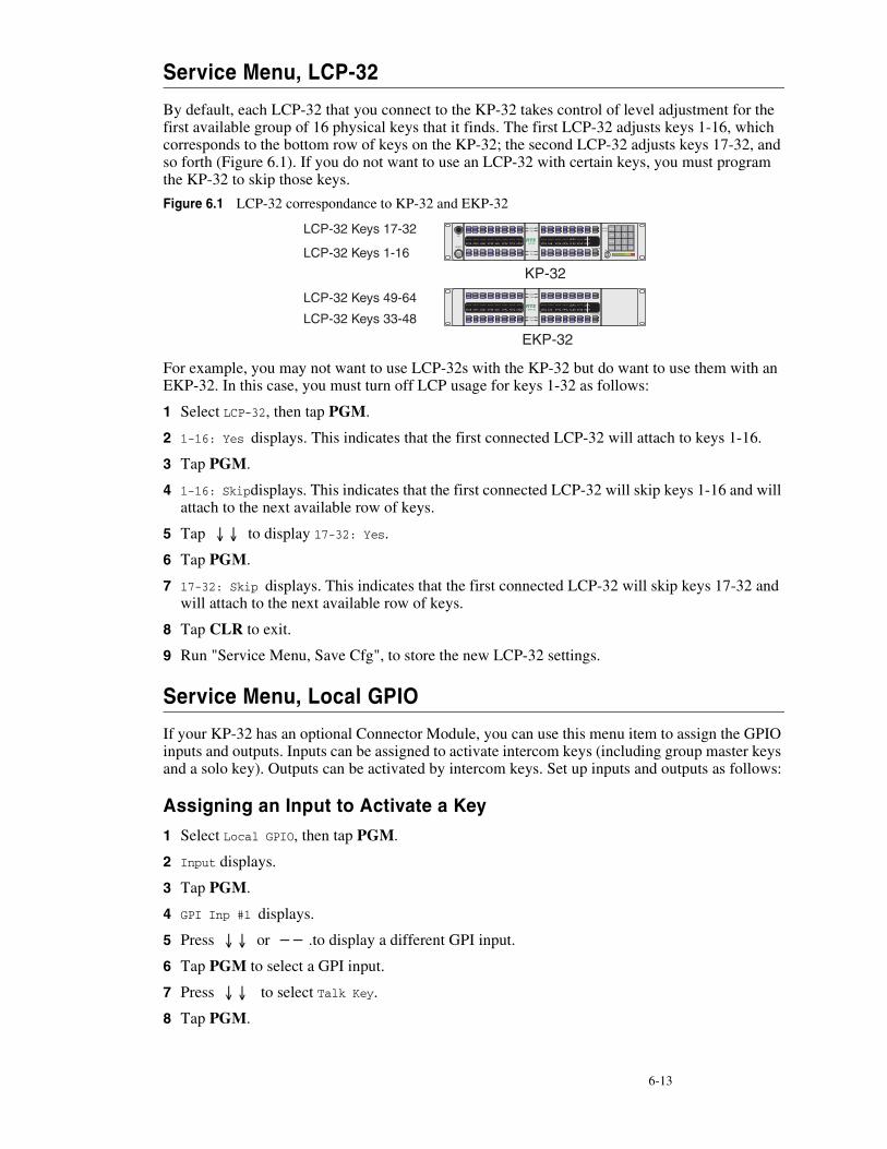
6-13
Service Menu, LCP-32
By default, each LCP-32 that you connect to the KP-32 takes control of level adjustment for the first available group of 16 physical keys that it finds. The first LCP-32 adjusts keys 1-16, which corresponds to the bottom row of keys on the KP-32; the second LCP-32 adjusts keys 17-32, and so forth (Figure 6.1). If you do not want to use an LCP-32 with certain keys, you must program the KP-32 to skip those keys.
Figure 6.1 LCP-32 correspondance to KP-32 and EKP-32
For example, you may not want to use LCP-32s with the KP-32 but do want to use them with an EKP-32. In this case, you must turn off LCP usage for keys 1-32 as follows:
1 Select LCP-32, then tap PGM.
2 1-16: Yes displays. This indicates that the first connected LCP-32 will attach to keys 1-16.
3 Tap PGM.
4 1-16: Skipdisplays. This indicates that the first connected LCP-32 will skip keys 1-16 and will attach to the next available row of keys.
5 Tap ↓↓ to display 17-32: Yes.
6 Tap PGM.
7 17-32: Skip displays. This indicates that the first connected LCP-32 will skip keys 17-32 and will attach to the next available row of keys.
8 Tap CLR to exit.
9 Run "Service Menu, Save Cfg", to store the new LCP-32 settings.
Service Menu, Local GPIO
If your KP-32 has an optional Connector Module, you can use this menu item to assign the GPIO inputs and outputs. Inputs can be assigned to activate intercom keys (including group master keys and a solo key). Outputs can be activated by intercom keys. Set up inputs and outputs as follows:
Assigning an Input to Activate a Key
1 Select Local GPIO, then tap PGM.
2 Input displays.
3 Tap PGM.
4 GPI Inp #1 displays.
5 Press ↓↓ or −− .to display a different GPI input.
6 Tap PGM to select a GPI input.
7 Press ↓↓ to select Talk Key.
8 Tap PGM.
6-14 K P - 3 2 U s e r M a n u a l
9 Tap Key displays.
10Tap the intercom key that you want to assign. This is the key that will activate when the GPI input activates.
11Tap CLR to exit, or BACK to back up and make more assignments.
12Run Service Menu, Save Cfg", to store local GPIO settings.
Assigning an Input to Activate a Key Group
1 Select Local GPIO, then tap PGM.
2 Input displays.
3 Tap PGM.
4 GPI Inp #1 displays.
5 Press ↓↓ or −− to display a different GPI input.
6 Tap PGM to select a GPI input.
7 Press ↓↓ to select Group.
8 Tap PGM.
9 By default, Group 1 displays. Press ↓↓ or −− .to display a different group.
10Tap PGM. An arrow will appear to indicate that the group is now selected. For example, if you press PGM to select Group 1, →Group 1 displays.
11Tap CLR to exit, or BACK to back up and make more assignments.
12Run Service Menu, Save Cfg, to store local GPIO settings.
Removing an Input Assignment
1 Select GPIO, then tap PGM.
2 Press ↓↓ or −− if necessary to select Input.
3 Tap PGM.
4 Press ↓↓ or −− .to display the GPI input that you want to remove.
5 Tap PGM.
6 Press ↓↓ to select Not Asgnd.
7 Tap PGM.
8 →Not Asgnd displays. The arrow indicates that "Not Assigned" is the new selection.
9 Tap CLR to exit.
10Run Service Menu, Save Cfg, to store local GPIO settings.
Adding or Removing a GPI Output Key Assignment
1 Select Local GPIO, then tap PGM.
2 Input displays.
3 Press ↓↓ to display Output.
4 Tap PGM.
5 GPI Out #1 displays.
6-15
6 Press ↓↓ or −− to display a different GPI output.
7 Tap PGM to select a GPI output.
8 Tap Key displays. Also, if there is a key currently assigned to activate the selected GPI output, both LEDs for that key will be lit red. If there is no assignment, no LEDs will be lit red.
9 Tap an intercom key to add or remove the GPI output assignment.
10Tap CLR to exit, or BACK to back up and make more assignments.
11Run Service Menu, Save Cfg, to store local GPIO settings.
Service Menu, Matrix Out
This menu item allows the user to select between Normal or Hot Mic. In the Normal (defualt) setting audio from the Mic goes out to the Matrix when the talk key is latched. In the Hot Mic setting audio from the Mic goes out to the Matrix with out regard to the talk key’s state.
1 Select Matrix Out from the Service Menu, then tap PGM.
2 →Normal displays
3 Press ↓↓ to select either Normal or Hot Mic
4 Tap PGM
5 Tap CLR to exit
6 Run Service Menu, Save Cfg, to store Matrix Out settings.
Service Menu, Mic Select
This menu item allows the user to select between the Panel and Headset Mic. In the Normal (defualt) setting, audio from the Panel Mic used. In the Hdst Only, setting audio from the Headset Mic is used.This is used to force the use of the headset microphone even when the keypanel’s speaker is being used.
1 Select Mic Select from the Service menu, then tap PGM.
2 →Normal displays
3 Press ↓↓ to select either Normal or Hdst Only
4 Tap PGM
5 Tap CLR to exit
6 Run Service Menu, Save Cfg, to store Mic Select settings.
Service Menu, Min Volume
This menu item allows the user to set the minimum volume level for both the keypanel speaker and the headset speaker(s). This is the minimum volume level available on the volume control located on the front panel of the KP-32.
1 Select Min Volume from the Service menu, then tap PGM.
2 →Speaker displays
3 Press ↓↓ to select either Speaker or Headset
4 Tap PGM
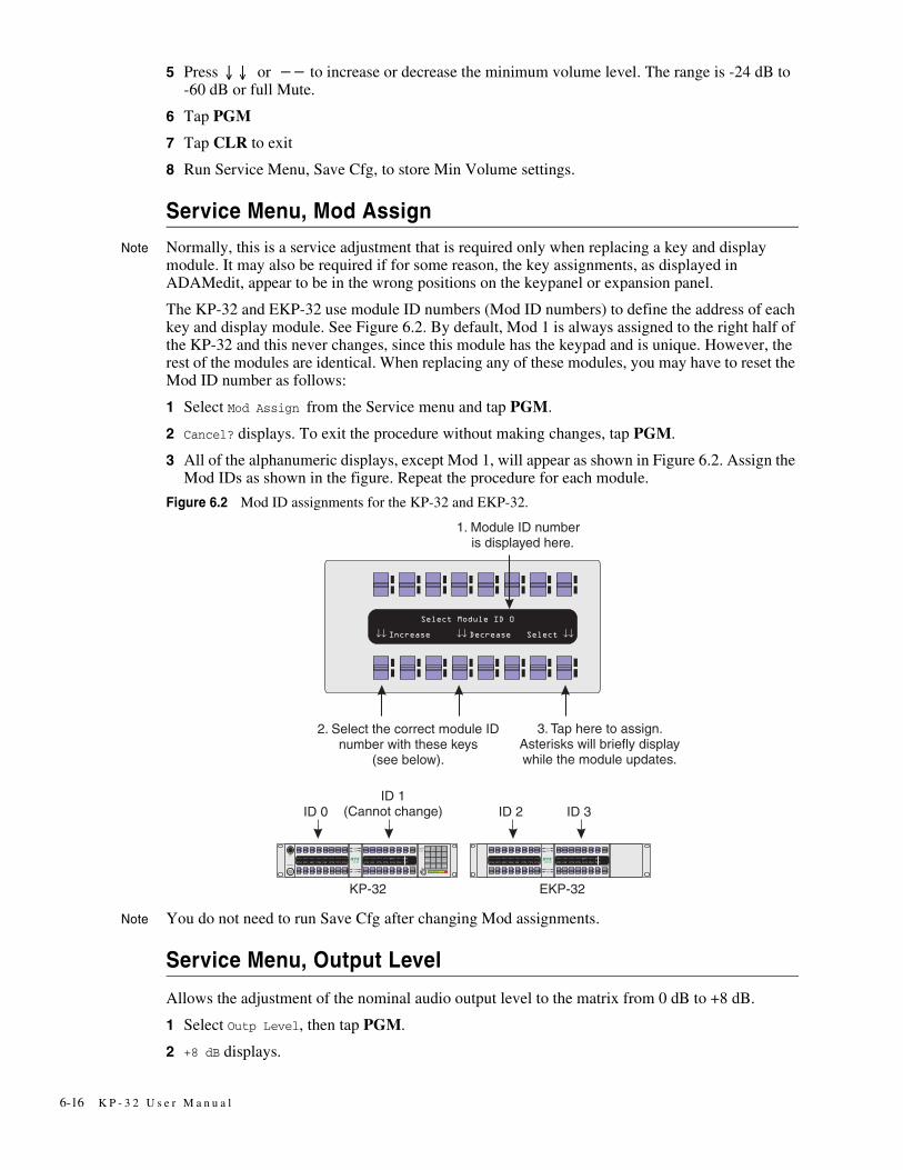
6-16 K P - 3 2 U s e r M a n u a l
5 Press ↓↓ or −− to increase or decrease the minimum volume level. The range is -24 dB to -60 dB or full Mute.
6 Tap PGM
7 Tap CLR to exit
8 Run Service Menu, Save Cfg, to store Min Volume settings.
Service Menu, Mod Assign
Note Normally, this is a service adjustment that is required only when replacing a key and display module. It may also be required if for some reason, the key assignments, as displayed in ADAMedit, appear to be in the wrong positions on the keypanel or expansion panel.
The KP-32 and EKP-32 use module ID numbers (Mod ID numbers) to define the address of each key and display module. See Figure 6.2. By default, Mod 1 is always assigned to the right half of the KP-32 and this never changes, since this module has the keypad and is unique. However, the rest of the modules are identical. When replacing any of these modules, you may have to reset the Mod ID number as follows:
1 Select Mod Assign from the Service menu and tap PGM.
2 Cancel? displays. To exit the procedure without making changes, tap PGM.
3 All of the alphanumeric displays, except Mod 1, will appear as shown in Figure 6.2. Assign the Mod IDs as shown in the figure. Repeat the procedure for each module.
Figure 6.2 Mod ID assignments for the KP-32 and EKP-32.
Note You do not need to run Save Cfg after changing Mod assignments.
Service Menu, Output Level
Allows the adjustment of the nominal audio output level to the matrix from 0 dB to +8 dB.
1 Select Outp Level, then tap PGM.
2 +8 dB displays.
6-17
3 −−decreases the level.
4 ↓↓ increase the level.
5 Tap PGM.
6 Tap CLR to exit.
7 Run Service Menu, Save Cfg, to store the Output Level settings.
Service Menu, Preamp Out (GPI Option Only)
Allows the user to choose how audio is routed to the Preamp Output connector. When Switched is chosen, keypanel audio is routed to the preamp output connector when a talk key is latched. When Hot Mic is chosen, audio is always available at the preamp output connector. When Disabled is chosen, keypanel audio is isolated from the preamp output connector.
1 Select Preamp Out, then tap PGM.
2 →Switched displays.
3 ↓↓ toggles between Switched, Hot Mic, and Disabled.
4 Tap PGM.
5 Tap CLR to exit
6 Run Service Menu, Save Cfg, to store the Preamp Out settings.
Service Menu, Reset Cfg
Reset Cfg restores all custom settings to the defaults and erases all stored autodial numbers.
Service Menu, Save Cfg
Save Cfg PGM saves custom settings that you have made in the Key Option or Service menus. made in the After customizing settings in the Key Option and Service menus, run Save Cfg to store your custom settings in non-volatile memory. This will assure protection of you settings when the keypanel is powered down. To erase all custom settings, run Service Menu, Reset Cfg.
Service Menu, Sidetone
Sidetone PGM lets you adjust the level of you own voice heard in the headphones when using a headset. Most people prefer some amount of sidetone to overcome the muffled sensation when talking, especially when wearing a full-muff headset. The maximum level is 0 dB.
Service Menu, Test Panel
Test Panel PGM lets you check the operation of all key and displays.
All alpha-numeric displays show a % symbol. Pressing down on any key (except the Headset / Vol. Sel. key) will cause OK to display. This verifies operation of the key. Tapping up or down on the Headset / Vol. Sel. key will cause the display to cycle through the available selections.
If latching is enabled, tapping up or down on any intercom key, or the Call waiting key, will cause the corresponding red LED to light. This verifies latching operation and also that the each red LED is OK.
Holding any key in the up or down position will cause the corresponding green LED to light. This verifies operation of the green LEDs.
6-18 K P - 3 2 U s e r M a n u a l
Tapping any keypad button (except CLR) will cause the keypad button name to appear in the Call waiting window. This verifies operation of the keypad buttons.
Tap CLR to quit.
Service Menu, Tone Gen
Tone Gen PGM turns the KP-32 tone generator on or off. You can use the tone generator to check the audio path from the keypanel to the matrix and back.
Tap CLR to quit.
Note The microphone is muted when the tone generator is active.
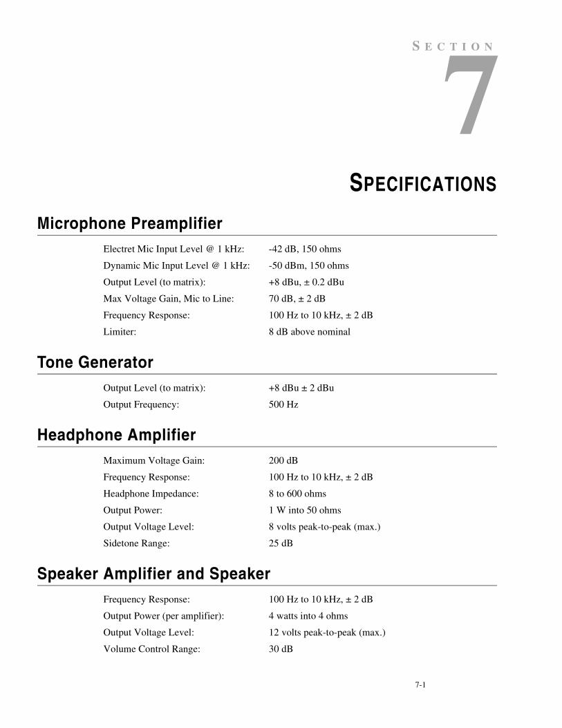
7-1
S E C T I O N
CHAPTER 7SPECIFICATIONS
Microphone PreamplifierElectret Mic Input Level @ 1 kHz: -42 dB, 150 ohms
Dynamic Mic Input Level @ 1 kHz: -50 dBm, 150 ohms
Output Level (to matrix): +8 dBu, ± 0.2 dBu
Max Voltage Gain, Mic to Line: 70 dB, ± 2 dB
Frequency Response: 100 Hz to 10 kHz, ± 2 dB
Limiter: 8 dB above nominal
Tone GeneratorOutput Level (to matrix): +8 dBu ± 2 dBu
Output Frequency: 500 Hz
Headphone AmplifierMaximum Voltage Gain: 200 dB
Frequency Response: 100 Hz to 10 kHz, ± 2 dB
Headphone Impedance: 8 to 600 ohms
Output Power: 1 W into 50 ohms
Output Voltage Level: 8 volts peak-to-peak (max.)
Sidetone Range: 25 dB
Speaker Amplifier and SpeakerFrequency Response: 100 Hz to 10 kHz, ± 2 dB
Output Power (per amplifier): 4 watts into 4 ohms
Output Voltage Level: 12 volts peak-to-peak (max.)
Volume Control Range: 30 dB
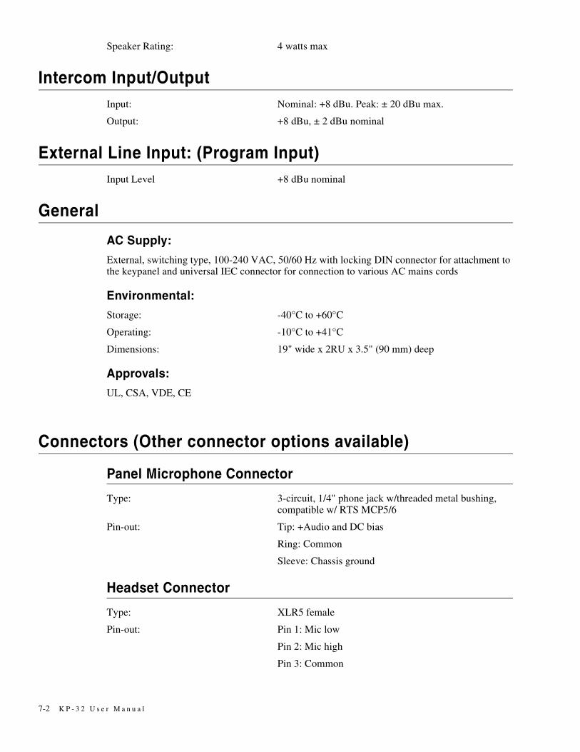
7-2 K P - 3 2 U s e r M a n u a l
Speaker Rating: 4 watts max
Intercom Input/OutputInput: Nominal: +8 dBu. Peak: ± 20 dBu max.
Output: +8 dBu, ± 2 dBu nominal
External Line Input: (Program Input)Input Level +8 dBu nominal
General
AC Supply:
External, switching type, 100-240 VAC, 50/60 Hz with locking DIN connector for attachment to the keypanel and universal IEC connector for connection to various AC mains cords
Environmental:
Storage: -40°C to +60°C
Operating: -10°C to +41°C
Dimensions: 19" wide x 2RU x 3.5" (90 mm) deep
Approvals:
UL, CSA, VDE, CE
Connectors (Other connector options available)
Panel Microphone Connector
Type: 3-circuit, 1/4" phone jack w/threaded metal bushing,compatible w/ RTS MCP5/6
Pin-out: Tip: +Audio and DC bias
Ring: Common
Sleeve: Chassis ground
Headset Connector
Type: XLR5 female
Pin-out: Pin 1: Mic low
Pin 2: Mic high
Pin 3: Common
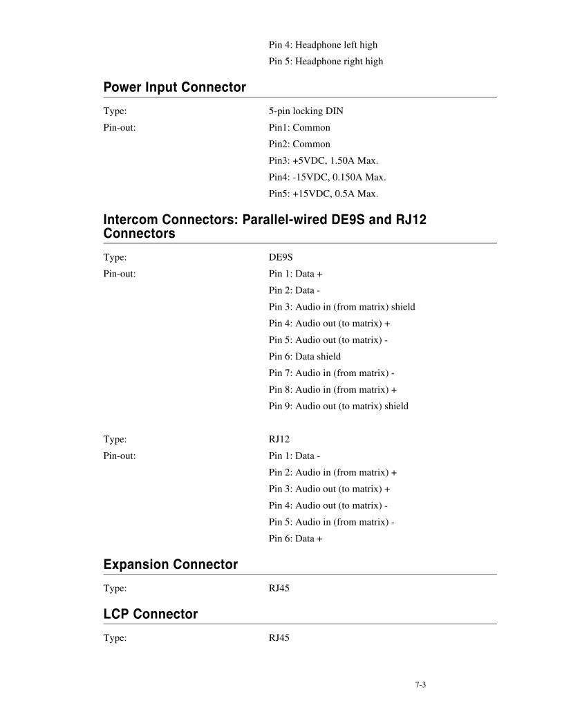
7-3
Pin 4: Headphone left high
Pin 5: Headphone right high
Power Input Connector
Type: 5-pin locking DIN
Pin-out: Pin1: Common
Pin2: Common
Pin3: +5VDC, 1.50A Max.
Pin4: -15VDC, 0.150A Max.
Pin5: +15VDC, 0.5A Max.
Intercom Connectors: Parallel-wired DE9S and RJ12 Connectors
Type: DE9S
Pin-out: Pin 1: Data +
Pin 2: Data -
Pin 3: Audio in (from matrix) shield
Pin 4: Audio out (to matrix) +
Pin 5: Audio out (to matrix) -
Pin 6: Data shield
Pin 7: Audio in (from matrix) -
Pin 8: Audio in (from matrix) +
Pin 9: Audio out (to matrix) shield
Type: RJ12
Pin-out: Pin 1: Data -
Pin 2: Audio in (from matrix) +
Pin 3: Audio out (to matrix) +
Pin 4: Audio out (to matrix) -
Pin 5: Audio in (from matrix) -
Pin 6: Data +
Expansion Connector
Type: RJ45
LCP Connector
Type: RJ45
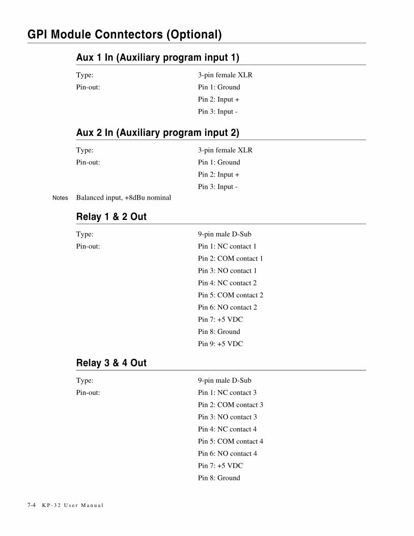
7-4 K P - 3 2 U s e r M a n u a l
GPI Module Conntectors (Optional)
Aux 1 In (Auxiliary program input 1)
Type: 3-pin female XLR
Pin-out: Pin 1: Ground
Pin 2: Input +
Pin 3: Input -
Aux 2 In (Auxiliary program input 2)
Type: 3-pin female XLR
Pin-out: Pin 1: Ground
Pin 2: Input +
Pin 3: Input -
Notes Balanced input, +8dBu nominal
Relay 1 & 2 Out
Type: 9-pin male D-Sub
Pin-out: Pin 1: NC contact 1
Pin 2: COM contact 1
Pin 3: NO contact 1
Pin 4: NC contact 2
Pin 5: COM contact 2
Pin 6: NO contact 2
Pin 7: +5 VDC
Pin 8: Ground
Pin 9: +5 VDC
Relay 3 & 4 Out
Type: 9-pin male D-Sub
Pin-out: Pin 1: NC contact 3
Pin 2: COM contact 3
Pin 3: NO contact 3
Pin 4: NC contact 4
Pin 5: COM contact 4
Pin 6: NO contact 4
Pin 7: +5 VDC
Pin 8: Ground
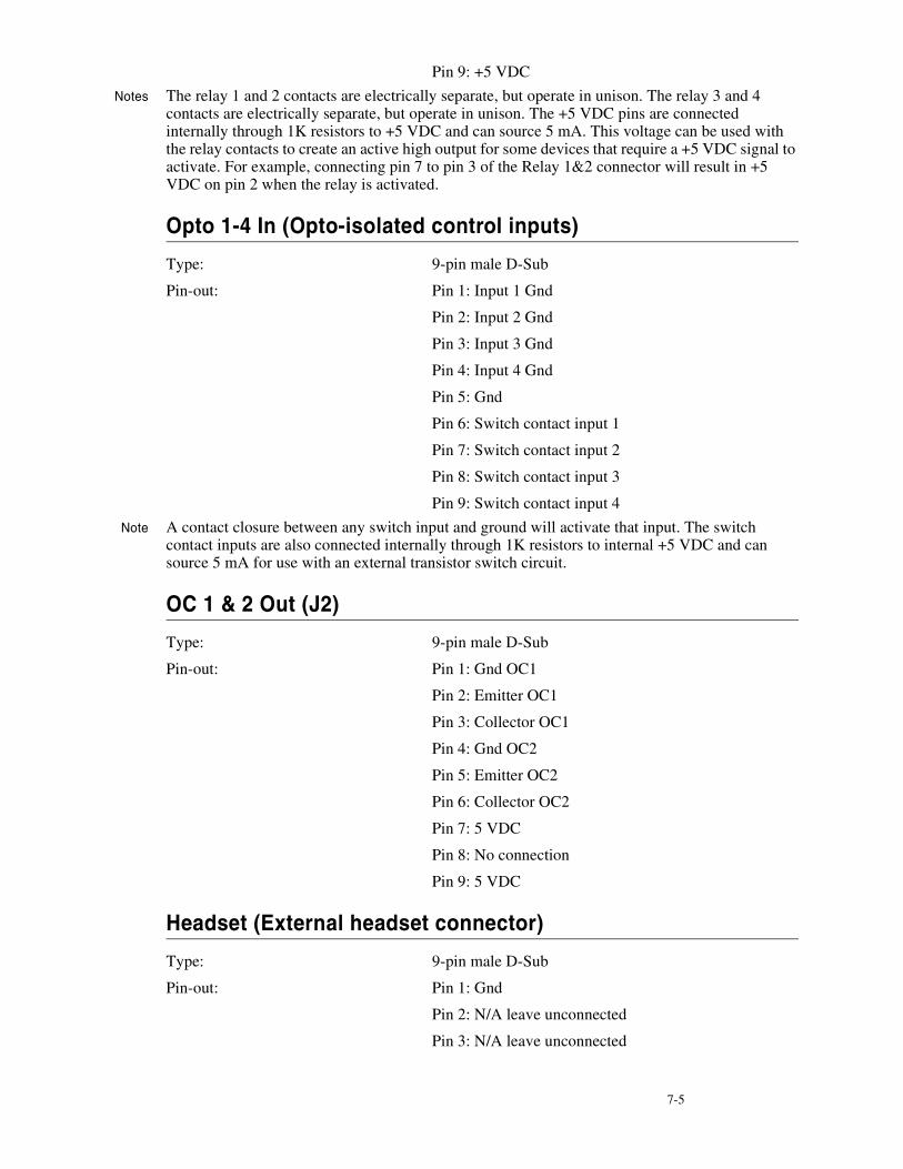
7-5
Pin 9: +5 VDC
Notes The relay 1 and 2 contacts are electrically separate, but operate in unison. The relay 3 and 4 contacts are electrically separate, but operate in unison. The +5 VDC pins are connected internally through 1K resistors to +5 VDC and can source 5 mA. This voltage can be used with the relay contacts to create an active high output for some devices that require a +5 VDC signal to activate. For example, connecting pin 7 to pin 3 of the Relay 1&2 connector will result in +5 VDC on pin 2 when the relay is activated.
Opto 1-4 In (Opto-isolated control inputs)
Type: 9-pin male D-Sub
Pin-out: Pin 1: Input 1 Gnd
Pin 2: Input 2 Gnd
Pin 3: Input 3 Gnd
Pin 4: Input 4 Gnd
Pin 5: Gnd
Pin 6: Switch contact input 1
Pin 7: Switch contact input 2
Pin 8: Switch contact input 3
Pin 9: Switch contact input 4
Note A contact closure between any switch input and ground will activate that input. The switch contact inputs are also connected internally through 1K resistors to internal +5 VDC and can source 5 mA for use with an external transistor switch circuit.
OC 1 & 2 Out (J2)
Type: 9-pin male D-Sub
Pin-out: Pin 1: Gnd OC1
Pin 2: Emitter OC1
Pin 3: Collector OC1
Pin 4: Gnd OC2
Pin 5: Emitter OC2
Pin 6: Collector OC2
Pin 7: 5 VDC
Pin 8: No connection
Pin 9: 5 VDC
Headset (External headset connector)
Type: 9-pin male D-Sub
Pin-out: Pin 1: Gnd
Pin 2: N/A leave unconnected
Pin 3: N/A leave unconnected

7-6 K P - 3 2 U s e r M a n u a l
Pin 4: N/A leave unconnected
Pin 5: Balanced dynamic mic input +
Pin 6: Gnd
Pin 7: Headset Listen Out Left
Pin 8: Headset Listen Out Right
Pin 9: Balanced dynamic mic input -
Note Mic input -60 dBu nominal. Headset out 0.325 watts into 8 ohms.
Foot Switch/Speaker
Type: 9-pin male D-Sub
Pin-out: Pin 1: Gnd
Pin 2: Speaker Minus (-)
Pin 3: Gnd
Pin 4: No connection
Pin 5: Foot Switch
Pin 6: Speaker Plus (+)
Pin 7: No connection
Pin 8: No connection
Pin 9: Gnd
Note A switch contact closure from the footswitch input to ground will activate the footswitch input.
MIC In (J7) Unbalanced Panel Microphone Input
Type: 3-pin female XLR
Pin-Out: Pin 1: Shield (circuit common)
Pin 2: DC bias and Audio Plus (+)
Pin 3: GND
Note Input level -42.5 dBu nominal.
MIC Out (J8) Balanced Microphone Output
Type: 3-pin male XLR
Pin-out: Pin 1: Shield (circuit common)
Pin 2: Audio output +
Pin 3: Audio output -
Note Output level +8 dBu nominal (balanced).
8-1
S E C T I O N
CHAPTER 8KP9X KEYPAD SEQUENCE QUICKREFERENCE
KP9X DISPLAY SEQUENCESFUNC DISPLAY 0 . Diagnostics mode.
FUNC DISPLAY 1 . Display port number.
FUNC DISPLAY 2 . Display level 2 talk assignments.
FUNC DISPLAY 3 . Display listen assignments.
FUNC DISPLAY -8 Display setup page assignments.
FUNC DISPLAY ↓↓ or − − to select items as follows:
ID PGM: Display the calculated port number. CLR to end.
Lev2 PGM: Display level 2 talk assignments. CLR to end.
Lstn PGM: Display listen assignments. CLR to end.
Name PGM: Display crosspoints closed to this keypanel. CLR to end.
Type PGM: Display level 1 talk key assignment types. CLR to end.
Mtx PGM: Display matrix ID for all level 1 talk assignments. CLR to end.
Tone PGM: Turn on tone generator. CLR to end.
Epnl PGM: Display setup page assignments. Mn=KP-32 top row keys. X1=KP-32 bottom row key. X2=EKP-32 top row keys. X3=EKP-32 bottom row keys.
Gain PGM: Port / party line listen gain. Turn on listen key. ↓↓ or − − to change gain.
VRst PGM: Reset all port / party line gains to 0dB.
Asgn PGM: Display key assignments that are not currently accessible.
Test PGM: Test keys and displays. CLR to end.
Vxxx : Display keypanel firmware version. CLR to end.
KP9X SETUP PAGE ASSIGNMENT1 Tap E-PNL.
2 Select a setup page: tap 1 , or 2 , etc.
8-2 K P - 3 2 U s e r M a n u a l
3 Tap PGM.
4 Tap any key in top row to assign page to top row. Tap any key in bottom row to assign page to bottom row.
KEY ASSIGNMENTS USING KEYPAD NUMERIC ENTRY1 For talk level 2 assignment only: Tap 0 0 .
2 Select the key assignment type:
NUM Intercom port.
PL Party line.
AUTO Auto function.
FUNC SLIST Special list.
FUNC IFB IFB
FUNC ISO Camera ISO
FUNC RELAY Relay or GPI output.
3 Auto function assignment only: Tap an additional number to select the desired auto function:
1 Auto listen
2 Auto follow
3 Auto mute
4 Auto reciprocal
5 All call
6 DIM (talk level 2 only, for point-to-point key)
7 Auto table (use only with IFB)
4 Trunked intercoms only: Select an intercom matrix (tap 1 , or 2 etc.).
5 Tap one or more number keys to select the desired port number, party line number, etc:
6 If the destination is in the local matrix, just enter the number.
7 If the destination is in a remote matrix, you must always enter at least 3 digits, so for example to assign port 1 you must enter 0 0 1 .
8 Tap PGM.
9 Tap down on a key to assign talk. Tap up to assign listen.
KP9X PHONE OPERATION
KP9X Hang-up Sequence
1 Turn off the TIF talk key.
2 On the keypad, tap PHONE-CLR.
3 Turn the TIF talk key on, then off. The TIF key talk and listen indicators will turn off and the TIF-951 "OFF" LED will activate.
8-3
KP9X Dial Sequence
1 Activate the TIF listen key (listen LED green).
2 Make sure the TIF talk key is off (Talk LED off).
3 On the keypad, tap CLR-PHONE-PGM.
4 Activate the TIF talk key (talk LED turns green). The "ON" LED at the TIF-951 will activate, and you should hear dial tone at the KP-32.
5 Dial the telephone number. Digits scroll in the display above the TIF talk key.
6 When the far end answers, you can dial additional digits (to access a mail system or automated response system, etc.). When finished dialing, momentarily turn off the TIF talk key to end dialing mode (talk LED turns red).
7 Turn the TIF talk key back on for conversation.
KP9X Redial Sequence
1 Tap the PHONE key to activate dialing mode.
2 Tap "up" on the TIF key to activate listen.
3 Tap CLR 0 0 . The last phone number will redial.
4 After the number has dialed, click the PHONE key to end dialing mode.
5 If the far end answers, tap "down" on the TIF key to activate talk.
6 Use the KP9X hang-up sequence to hang up.
KP9X Autodial Sequences
Storing an Autodial Number in the TIF-951
1 Tap the PHONE key.
2 Tap the TIF talk key to latch it on.
3 Using the number keys on the keypad, dial the phone number that you want to store. The entire phone number sequence can have up to 30 digits.
Note To insert one or more pauses anywhere in the dialing sequence, enter CLR CLR 9 9 for each pause.
4 After dialing the telephone number, click CLR PGM, then enter a two-digit number (01, 02, etc. up to 32) that you will use as the autodial number.
5 After storing the autodial number, hang up using the KP9X hang-up sequence.
Dialing an Autodial Number Stored in the TIF-951
1 Tap the PHONE key to activate dialing mode.
2 Tap "down" on the TIF talk key to latch it in the on position.
3 Tap CLR followed by the autodial number (01, 02, etc.).
4 When finished dialing, click the PHONE key again to exit dialing mode.
5 Hang up using theKP9X hang-up sequence.

8-4 K P - 3 2 U s e r M a n u a l
This Page Left Blank Intentionally
9-1
S E C T I O N
CHAPTER 9KP-32 MENU SYSTEM QUICK REFERENCE
MENU ACCESS1 Clear all names from the Call waiting display (if not clear) by tapping "up" one or more times
on the Call waiting key.
2 Tap MENU to activate the menu system.
3 Press ↓↓ to scroll forward through the list of menus. Press − − to scroll back.
4 Tap FWD or PGM to enter a menu. Tap BACK to exit a menu.
5 Within a menu:
• Press ↓↓ or − − to scroll.
• Tap FWD or PGM to select an item.
• Tap BACK to cancel a selection or to go back to the previous menu level.
MENU LISTDISPLAY MENU KEY ASSIGN MENU KEY OPTION MENU SERVICE MENUAsgn Type Matrix Auto Dial* Aux Inputs
Chans On Key Assign Menu, Pt-to-Pt Chime* Dim*
Key Groups Party Line Key Groups* Disply Dim*
Key List IFB Solo* DSP Func*
Level 2 Spcl List Hdst Sel*
Listen Sys Relay LCP-32*
Matrix Camera ISO Local GPIO*
Panel ID UPL Resrc Matrix Out*
Version Auto Func Mic Select*
Key Gain Min Volume*
Reset Vols Mod Assign*
Setup Page Outp Level*
Preamp Out*
Reset Cfg
Save Cfg
Sidetone*
Test Panel
Tone Gen* Run Save Cfg, to save these settings.

9-2 K P - 3 2 U s e r M a n u a l
This Page Left Blank Intentionally
10-1
S E C T I O N
CHAPTER 10MODE 2 OPERATION
Section 2
Switch 4: Call Flash Timeout*
When the switch is closed the menu and indefinite talking is disabled.
Switch 5: Footswitch Enable / Disable*
Amber talk LEDs indicate a latched talk key.
Section 3
LED Indications for Intercom Keys
Talk LED Indications
The talk LED is the lower LED for each key. The talk LED indications are as follows:
Continuous Red*
Talk is on and the keypanel operator can be heard at the destination.
Flashing Display Alpha ("In-use")*
The key is off, but someone is talking to the destination. This indication is provided for any local PL, IFB, ISO, or TIF key. It does not apply to remote IFB or ISO keys. This indication is provided so keypanels operators know when critical director communications are occurring. If you activate the key, either of two things will happen:
• If you activate the key and the talk LED turns continuous green, this indicates that you and the other keypanel operator are both talking to the destination.
• IFB keys only: If the talk LED flashes red when an IFB key is activated, this indicates that the other keypanel has a higher IFB priority and you cannot talk at this time.
Note The red "in-use" indication for TIF keys can be disabled in ADAMedit: In the ADAMedit Options menu, select Intercom Configuration, then click on the Options tab. Place a check mark next to "Don't generate talliesfor TIF and trunk use". Be sure to send the change to the intercom system. Note that this will also disable the flashing alpha display when talking to remote IFBs or ISOs as previously described.
10-2 K P - 3 2 U s e r M a n u a l
Solid Red Talk LED & Flashing Display Alternating Pattern of Alpha & (-**-) ("Busy")
You cannot talk at this time. This indication occurs when you activate a local IFB key that is already in-use by a keypanel with a higher IFB priority. It also occurs when you activate any key assigned to a remote destination, but there are currently no trunks available.
Note Flashing red is also the intended indication when attempting to talk to a remote IFB while someone else with a higher trunk IFB priority is already talking. However, this will require ADAM MC version later than 9.9.x and Trunk MC version later than 7.x.x. As of this writing, these versions are not implemented. Regardless of the indication provided, you will not be heard at the remote location if your keypanel has the lower trunk IFB priority. IFB trunk priorities are set in ADAMedit. (Click the "KP" button on the ADAMedit toolbar to access Keypanels / Ports setup, then click the "Edit" button, then click the "Advanced" tab. Enter the desired IFB priority in the fields provided. Be sure to send the change to the intercom system.)
Flashing Display Alpha (on time equal to off time)*
There is an incoming call from the destination assigned to the key. Activate the key to talk back.
Note The duration of incoming call flash is controlled by DIP switch 4 on the KP-32 back panel. See "Option Switch Settings" for further information.
Amber Talk LED This indicates that a key is ready to talk (key is on), but requires external footswitch activation to talk.
11-1
S E C T I O N
CHAPTER 11GLOSSARY
All Call For talk key assignment only. Activating an All Call key will also activate all talk keys to the left of the All Call key (up to, but not including another All Call key).
Alpha Alphas are the user-changeable names which identify destinations (intercom ports, party lines, etc). Change Alpha names for intercom ports using the Port Alpha button in ADAMedit. Change Alpha names for everything else using the Other Alpha button. When you assign a destination to a talk key, the alpha name will appear in the alphanumeric display for that key (on keypanels so equipped).
Auto Follow(AF)
A key assignment for listen keys only. Auto follow causes a key's listen assignment to always be the same as the talk assignment. Thus, if you change the talk assignment, you do not also have to change the listen assignment. You can manually activate an auto-follow listen key independently of the talk key. If you want auto-activation (or deactivation) of listen during talk, use one of the other auto key assignments, such as auto listen or auto mute.
AutoFunctions
Auto functions are special key assignments that work with other key assignments. For further information, see the glossary descriptions of individual auto functions: auto-follow, auto-listen, auto-reciprocal, auto-mute, auto-table, all-call, DIM.
Auto Listen(AL)
A key assignment for listen keys only. This assignment works like auto follow, except that listen automatically activates during talk, Auto listen is sometimes a good assignment for use with party lines or other non-keypanel devices that do not have talk-back control of matrix crosspoints.
Auto Mute(AM)
A key assignment for listen keys only. This assignment works like auto follow, except that listen automatically mutes during talk. Auto mute can help prevent feedback or echo when talking to certain destinations. In some cases, you may find it works better to disable talk latching for this type of key, because if you accidentally leave talk latched on you will never be able to hear the destination. To disable latching, in the Keypanels / Ports menu of ADAMedit, check the "D" check box for any talk key that has auto mute selected as the listen assignment.
AutoReciprocal
(AR)
A key assignment for listen keys only. This assignment forces you to continuously listen to whatever is assigned to the talk key. It is used commonly on keypanels which are not equipped with listen keys, to allow listening to party lines. It is also useful to force listening when it is desirable to have an operator continuously hear a party line or other source.
Auto Table(AT)
A key assignment for listen keys only, when the corresponding talk key is assigned to an IFB. Auto Table causes a listen key's assignment to always be the same as the Listen Source for whatever IFB is currently assigned to the talk key. (You define the Listen Source in ADAMedit during IFB setup.) Auto Table is convenient in a broadcast environment when a director needs 2-way communication with the IFB talent, AND the IFB keys are frequently reassigned during the course of a program to talk to new talent locations. Using ADAMedit, several IFBs can be set up in advance, and their Listen Sources can also be defined during setup. Then every time an IFB talk key is reassigned on a keypanel, the Listen Source for each new IFB will automatically become the listen key assignment for that key. For further information about Auto Tables, Listen Sources, and IFBs, search for "IFB" in ADAMedit help.
11-2 K P - 3 2 U s e r M a n u a l
Crosspoint The term "Crosspoint", like the term "Matrix" is inherited from intercom systems, such as the RTS CS9500, CS9600, and CS9700, that use a switching matrix to route intercom audio. In those systems, the crosspoints are the actual switches that close or open to connect or disconnect talk and listen paths. RTS ADAM, ADAM CS, and Zeus Intercom Systems do not actually use crosspoint switches, but use a technique called time division multiplexing (TDM), in which communications are routed as digital packets. However, use of the term "crosspoint" persists since packet routing basically accomplishes the same thing as conventional crosspoints: namely, connecting distinct talkers and listeners. In this sense, a crosspoint can be thought of simply as a communication link between any two points in the intercom system.
Destination A destination is anything that a talk key talks to or a listen key listens to. A destination can therefore be any port, party line, IFB, etc.
Dim "Dim" occurs in two contexts in RTS Digital Matrix Intercom Systems.First, there is the Dim Table feature. Dim tables are used to correct a feedback problem that can occur between two keypanels operating in close proximity that have keys assigned to talk/listen to a common destination. Dim tables are set up in ADAMedit (search for keyword "dim" in ADAMedit help. Once a dim table is set up, it can be assigned as a level 2 talk assignment for those keys that are causing the feedback problem. For information about how to make this assignment from a programmable keypanel, search for "Dim Table" in the keypanel manual index.There is also an adjustable speaker dim feature available on the KP-32 Keypanel. This causes the speaker or headphone volume to diminish by a preset amount whenever a talk key is activated. This can help to prevent occasional feedback between the speaker and microphone due to volume settings, microphone placement, etc. For setup and usage, search for "Speaker Dim" in the keypanel manual index.
GPIO General Purpose Input / Output. (You may also see this referred to simply as "GPI".) GPIO is a means of controlling devices using switch contact closures, DC voltages, or similar methods. For example, you can control a lighting system from keypanel keys, or key a transmitter from a talk key during transmit. Or, simply operate a light or buzzer for cueing. In ADAM, ADAM CS, and Zeus intercom systems, you can also control intercom events from external switches. For example, you can activate key assignments, close or open crosspoints, activate GPI outputs, etc.In CS9000 Series intercom systems, general purpose control outputs are provided by optional FR9528 Relay Frames (8 relays each). In those systems, a relay may be assigned to an intercom key on a keypanel using the Relay key assignment type. Pressing the intercom key activates the relay.ADAM, ADAM CS, and Zeus intercom systems all have a dedicated GPIO connector (J27 on a Zeus Frame, J903 on an ADAM CS Frame, and J11 on the XCP-ADAM-MC Master Controller Breakout Panel in an ADAM Intercom System). This connector supports 8 control inputs and 8 control outputs. Additionally, one or more UIO-256 Universal Input/Output frames may be connected to the intercom system. Each UIO-256 provides another 16 control inputs and 16 control outputs. Control outputs may be assigned to intercom keys using the Relay key assignment type, and the intercom keys can then control external devices the same as the FR9528. Control inputs can be assigned to activate "virtual" key assignments. (A virtual key assignment is a key assignment at an intercom port where there is not actually any keypanel connected. Basically, you use an external switch to act like a talk or listen key.) The control inputs and outputs can also be used as conditions for UPL statements in ADAMedit.Finally, there is a GPIO option available for the KP-12 keypanel, and a connector module option for the KP-32, which includes GPIO. These are referred to as "Local" GPIO, since they are assigned and used locally at the keypanel. Each local GPIO includes 4 control inputs and 4 control outputs.
IFB IFB (Interrupt Foldback) is a special type of communication in which a listener at a particular intercom output port normally hears an audio program source connected to a particular intercom input port. A keypanel operator can activate a key to interrupt the audio program source and then talk to the listener. Normal operation resumes when the keypanel operator releases the key.IFB is typically used to cue on-the-air talent. For example, the news anchor during a news broadcast typically listens to the broadcast audio mix in an earset (except that the news anchor's own voice audio is removed from the mix). A director at a keypanel can interrupt the broadcast audio to the news anchor's earset and provide new information to the news anchor. IFB could also be used with a PA (public address) system that normally broadcasts background music. The background
11-3
music can be interrupted while someone is talking over the PA.IFB's are set up by defining the IFB inputs and outputs using the intercom system configuration software. The intercom output port is called the IFB output and the program input port is called the IFB input. IFBs can also be given names which are meaningful to keypanel operators. Once an IFB has been set up and named, it can be assigned to any keypanel key (provided that IFB assignment has not been restricted or disabled in the intercom system configuration software). For further information about IFBs, search for "IFB" in ADAMedit help.
ISO (CameraISO)
ISO is a means for a keypanel operator to isolate a particular intercom port for private communication. While the intercom port is isolated, it can only hear audio from the keypanel operator. ISO is frequently used in television broadcasting to temporarily isolate a member of a camera party line. The isolated camera operator can then receive directions without interference from other audio traffic on the party line. ISOs are setup using the intercom system configuration software. Each ISO can also be given a name which is meaningful to keypanel operators. Once an ISO has been set up and named, it can be assigned to any keypanel key (provided that ISO assignment has not been restricted or disabled in the intercom system configuration software). For further information about ISOs, search for "ISO" in ADAMedit help.
Matrix "Matrix" is a term inherited from earlier point-to-point intercom systems, where all point-to-point communication was accomplished by closing specific switches in a switching matrix. Examples include the RTS CS9500, CS9600, and CS9700 Intercom Systems. In many instances, "Matrix" is used interchangeably with "Intercom System".RTS ADAM, ADAM CS, and Zeus Intercom Systems, on the other hand, do not use a switching matrix, but use a method called Time Division Multiplexing (TDM), in which communications are routed as digital packets. However, use of the term "matrix" persists since packet routing basically accomplishes the same thing as a conventional switching matrix: namely, connecting distinct talkers and listeners.
Party Line(PL)
A party line (also called a conference line) is a group of intercom ports which can always talk and/or listen to each other. Party lines have default names PL01, PL02 etc. These names can be changed to more meaningful names using Other Alpha setup in ADAMedit. Members are assigned to a party line using Party Line setup in ADAMedit. Once a party line has been set up, it can also be assigned to a keypanel key either from the configuration software or at a programmable keypanel. This allows the keypanel operator to talk and/or listen to the party line without being a member.IMPORTANT: Do not confuse special lists and party lines. A special list is used when a keypanel operator needs to occasionally talk or listen to a group of intercom ports that are otherwise unrelated. A party line is typically used when several users of non-keypanel devices (such as belt packs or camera intercoms) are engaged in a specific common activity and they need to talk and/or listen to each other all the time. Keypanels are almost never members of party lines (although they can be). However, a keypanel key can be assigned to occasionally talk or listen to a party line if desired. Just remember: party lines are primarily set up for party line members, with occasional access by keypanel operators, while special lists are set up exclusively for keypanel operators to talk or listen to several unrelated intercom ports.For specific information about party line setup, search for "PL" or "party line" in ADAMedit help.
Port The ports are the individual channels that devices are connected to. Devices include:·2-way communication devices, such as keypanels, belt packs etc.·Audio sources, such as broadcast feeds or background music·Miscellaneous audio output devices, such as powered loudspeakers, PA systems etc. Communication between Ports (Point-to-Point, or P-P)The audio signal from any input port can be routed to any output port. For example, during keypanel setup, you assign keypanel keys so that keypanel operators can talk and listen to other intercom ports. Communication of this type is called point-to-point communication. You can also route signals between intercom ports without keypanels. One way to do this is to force crosspoints in the Crosspoint Status screen of ADAMedit. Another way to do it is with a GPI input. Port ID Numbers and AlphasIntercom ports have identification numbers 001, 002 etc. These numbers cannot be changed, but may not be commonly known to intercom system users. Each intercom port also has a default name, called an "alpha", because this name appears in the alphanumeric displays on keypanels when you assign the ports to keys for talking and listening. The default alpha names are N001, N002 etc. These default alpha names can be changed to ones that are meaningful to keypanel operators using Port Alpha setup In ADAMedit. (Click the "Port Alpha"
11-4 K P - 3 2 U s e r M a n u a l
button in ADAMedit, then press F1 on the computer keyboard if you need help.)Intercom Data Groups and Port Number CalculationFor data routing purposes, port numbers are arranged in groups of 8 sequential intercom ports. In an ADAM or ADAM CS Intercom System, each Audio I/O card comprises one data group. In a Zeus Intercom System, each group of 8 port connectors comprises a data group. Within each data group, each keypanel is uniquely identified by its address setting. Whenever you display the Panel ID, the intercom system determines which data group the keypanel is connected to, and also the address setting. It then reports the calculated address. For example, suppose a keypanel is connected to data group 3 and the keypanel address is set to 5. Since each data group consists of 8 sequential intercom ports, the calculated port number for this keypanel will be (2*8) + 5, or 21. This is the total of all intercom port numbers on the first 2 data groups, plus the offset of 5 ports into the third data group.Port GainsRTS Keypanels are calibrated to send and receive audio at the standard operating levels of the intercom system. No audio gain adjustment is normally required when connecting these. However, many other types of devices may not operate at the standard intercom system levels. To assure signal level compatibility between the various types of audio devices connected to the intercom system, there are separate analog input and output gain adjustments for each intercom port. It is also possible to adjust the listen gain for any specific intercom port when listening to any other specific intercom port. This is called the point-to-point listen gain, or crosspoint gain. For example, a keypanel operator might want to monitor a music source connected at some intercom port, but at a reduced audio level so that it does not interfere with normal intercom communications. The crosspoint gain can be reduced for the keypanel port listening to the port where the music source is connected.Analog gain adjustment is only available using ADAMedit. Crosspoint gains can be adjusted either within ADAMedit or from a programmable keypanel. For further information on any gain adjustment in ADAMedit, search for keyword "gain" in ADAMedit help. For procedures to adjust gain from a programmable keypanel, look for "gain" in the manual index.
Relay Relay is used interchangeable with GPI output. The relay feature works with the 16 GPI outputs of an optional UIO-256 Universal Input / Output Frame, and with the relay outputs of an FR9528 Relay Frame. The relay feature also works with the 8 GPI outputs of an ADAM, ADAM CS, or Zeus intercom system (J27 on a Zeus Frame, J903 on an ADAM CS Frame, and J11 on the XCP-ADAM-MC Master Controller Breakout Panel in an ADAM Intercom System). You can assign a keypanel key to control a GPI output from any of these devices, and then use that key and output to control an external device. For example, you could use a keypanel key to control lighting. Or, you could assign a relay as a level 2 talk key assignment in a stacked talk key arrangement to both send audio and key a device, such as a paging amplifier or a 2-way radio.
Special List A special list is a means for a keypanel operator to talk and/or listen to several unrelated destinations using a single key. Special lists are useful for group call or zone paging. Special list members are defined in the intercom configuration software. Once a special list has been configured, it can be assigned to a keypanel key.A special list is a group of intercom ports that a keypanel operator can talk or listen to by activating a single key. Special lists are typically used for paging, all call, group call etc. Special lists have default names SL01, SL02 etc. These names can be changed using Other Alpha setup. You define the members of the special list using Special List setup. Once a special list has been set up, you typically assign it to a keypanel key using Keypanel setup. The keypanel operator can then activate the special list key to talk or listen to all members of the special list.IMPORTANT: Do not confuse special lists and party lines. A special list is used when a keypanel operator needs to occasionally talk or listen to a group of intercom ports that are otherwise unrelated. A party line is typically used when several users of non-keypanel devices (such as belt packs or camera intercoms) are engaged in a specific common activity and they need to talk and/or listen to each other all the time. Keypanels are almost never members of party lines (although they can be). However, a keypanel key can be assigned to occasionally talk or listen to a party line if desired. Just remember: party lines are primarily set up for party line members, with occasional access by keypanel operators, while special lists are set up exclusively for keypanel operators to talk or listen to several unrelated intercom ports.For specific information about special list setup, search for "special list" in ADAMedit help.
Stacked Key See the descriptions for talk level, talk level 2.

11-5
Talk Level 1 Talk level 1 is the normal talk key assignment. This is the assignment that normally appears in the alphanumeric display (on keypanels so equipped). You may add a talk level 2 assignment to activate a second device along with talk level 1.
Talk Level 2 Talk level 2 is used with stacked talk keys. A stacked talk key activates two types of communication at once. For example, a stacked talk key could simultaneously activate audio output to a transmitter and key the transmitter using a relay. The audio output is called the level l assignment and the relay is called the level 2 assignment.
Trunking Trunking is a method of interconnecting two or more independent intercom systems. The connection is accomplished by reserving one or more audio ports in each of the intercom systems for use as audio links between the systems. A special device, called a Trunking Master Controller, is required to control access and usage for the trunked intercom ports. A configuration utility, called CStrunk, is used to set up the Trunking Master Controller.

11-6 K P - 3 2 U s e r M a n u a l
This Page Left Blank Intentionally