konfokal- og multifoton laser scanning mikroskopi (clsm og...
TRANSCRIPT
P. Johannes Helm, M.Sc. PhD
by
Center for Molecular Biology and
Neuroscience
and
Department of Anatomy
Institute of Basic Medical Sciences
University of Oslo
Oslo
Konfokal- og multifoton laser scanning mikroskopi (CLSM og MPLSM) i den biomedisinske forskningen
/ Confocal and Multiphoton Laser Scanning Microscopy in the
Life Sciences -
Seminar i dynamiske målemetoder /
Seminar in Dynamic Measurement Techniques,
Univ. Oslo & NTNU, Trondheim, Feb. 2003
&

beamsplitter
The Confocal Scanning Laser Microscope (CSLM)
microscope slide, specimen, and cover slip
objective
"ocular", here:scanning lens
scanning mirror
det
ect
or
light source
detection pinhole
illumination pinhole
Confocal scanning laser microscopy is an established and commonly applied technology. Comparedto classical wide field microscopy, lateral resolution is increased and axial resolution is well definedand can be quantified. Briefly, the projections of small apertures in front of the light source and thedetector overlap in the object space, hence are "confocal". Thus, by suppressing light emanating fromlocations out of the focus, signal detection is confined to the focal region, and optical slices as well as3D-images can be recorded by scanning the specimen. However, the number of detected photons perpicture element is considerably smaller than, e.g., on a widefield video microscope. High spatialresolution thus entails a penalty in form of a comparatively poor signal to noise ratio, especially onfluorescent specimens and in spite of the fact that all the tracer molecules located in the illuminationlight cone emanating from the objective front lens are permanently being excited, hence bleachedunnecessarily. If one uses a laser for illumination, no light source pinhole is required any longerbecause of the negligible divergence of the quasi-parallel beam.
Selected References: -M. Minsky (1957/1961) "U.S. Patent #3013467, Microscopy Apparatus", (see here for a CV and protrait of Marvin Minsky) -M. Petráň, M. Hadravsky, D Egger & R. Galambos (1968) "Tandem-scanning reflected-light microscope" JOSA 58:661-664 -K. Carlsson & A. Liljeborg (1989) "A confocal laser microscope scanner for digital recording of optical section series" J. Microscopy 153(2):171-180 -J. Pawley (ed.) "Handbook of Biological Confocal Microscopy, 2nd edition", Plenum Press, New York and London, 1995, ISBN: 0-306-44826-2

SM:
IR-blocking filtercondenser
detector 2
Beam expander
Titanium-Sapphire Laser
Nd:YVO4 pumplaser
beamsplitter
microscope slide, specimen, and cover slip
objective
"ocular", here:scanning lens
scanning mirror
detector 1
The Multi Photon Scanning Laser Microscope (MPSLM)
Another approach for high resolution 3D-fluorescence-imaging on a light microscope is the MPSLM. While, during a single-photon excitationprocess, one photon with a suitable wavelength λexc, 1 is being absorbed by the dye-molecule, which then emits at least one luminescencephoton, a number n>1 of photons of suitable wavelengths λexc, n can be absorbed by the dye-molecule in order to generate the same or a similarluminescence. Unlike λexc, 1 which commonly is a visible or near ultraviolet wavelength for dyes popular in cell biology, the wavelengths λexc, nare normally located in the near infrared region of the electromagnetic spectrum, following conservation laws for energy, angular momentum a.s. o., and quantum mechanical selection rules. However, during a multi-photon excitation process of fluorescence, the stimulating photons haveto hit the dye-molecule during a time interval which is short compared to average fluorescence decay times, i.e., practically speaking, at once.Thus, a very large flux of photons is required to initialise a multi-photon process. In the light cone of a microscope objective of high numericalaperture, the steep gradient of the photon flux along the optical axis allows for multi-photon excitation processes in the focal region, only.Thus, excitation is confined to the focus, i.e. the system is quasi confocal. MPLSM has the following main advantages compared to CL- The system inherently performs quasi-confocal; it is possible to define and quantify an axial resolution. - No bleaching of the dye is going to appear outside the focal region. - A detector aperture is not required any longer, so that a) even those fluorescence photons can be detected, which are scattered off the ballistic optical path to the detector by scatterers in the specimen, and b) another detector can be placed under the condenser so that the solid angle for fluorescence detection is drastically increased, sometimes virtually doubled. - Aberration effects in the specimen are considerably less pronounced at IR wavelengths than at visible or UV wavelengths, so that even dye substances normally requiring ultraviolet light, when stimulated during a single photon process, can be excited at wavelengths more suitable for the microscope optics than those of ultraviolet light. The main disadvantage is the comparatively high cost of the equipment and the required laboratory infrastructure. The fact that it is difficult toseparately excite common fluorophores as, e.g., TRITC and FITC often applied simultaneously in multi staining experiments might sometimesalso be considered as disadvantageous, e.g. in case of excitation ratio imaging of Fura-2 stained specimens. The latter problem is caused by thebroad wavelength band for multi-photon excitation of most dyes.
Selected References: -Maria Göppert-Mayer (1931) "Über Elementarakte mit zwei Quantensprüngen (Göttinger Dissertation)" Annalen der Physik 9:273-294 -Winfried Denk, James H. Strickler & Watt W. Webb (1990) "Two-Photon Laser Scanning Fluorescence Microscopy" Science 248:73-76, -Winfried Denk & Karel Svoboda (1997) "Photon Upmanship: Why Multiphoton Imaging is more than a Gimmick" Neuron 18:351-357, -Chris Xu, R M Williams, Warren Zipfel & Watt W Webb (1996) "Multiphoton excitation cross-sections of molecular fluorophores” Bioimaging 4:198-207

Some photographic views and some
drawings (The photographic images were taken and scanned byMrs. Carina Knudsen, Lab. Eng., and Mr. Gunnar F.Lothe, Lab. Eng., both at IMBA, Univ. of Oslo, Oslo,Norway, their help is gratefully acknowledged)

Figure 1: DM RXA Here, the scanner head of the CLSM unit (#1), model ”TCS SP”(Leica Microsystems Heidelberg GmbH, Mannheim, FRG) can beseen mounted on a large frame research microscope model ”DMRXA” (#2) (Leica Microsystems Wetzlar GmbH, Wetzlar, FRG)equipped with state of the art imaging and contrast techniques and alarge set of high quality objectives. The software, ”LCS vs. 2.770”(Leica Microsystems Heidelberg GmbH, Mannheim, FRG), whichthe user applies to control the microscope, is installed on a PC (#3)operated by OS ”Microsoft Windows NT 4 SP 6”. In addition to theconfocal scanning unit, a CCD or video camera can be linked to themicroscope by means of a lateral C-mount adapter. The electronic control unit of the CSLM can barely be seen on thisimage (#4). The scanner head can be attached to any of the three microscopesmounted on the optical table (#5), which is a model ”RS 4000”mounted on model ”I 2000” pneumatic vibration isolators (bothNewport - Micro Contrôle, Irvine, CA, USA and Évry, France).
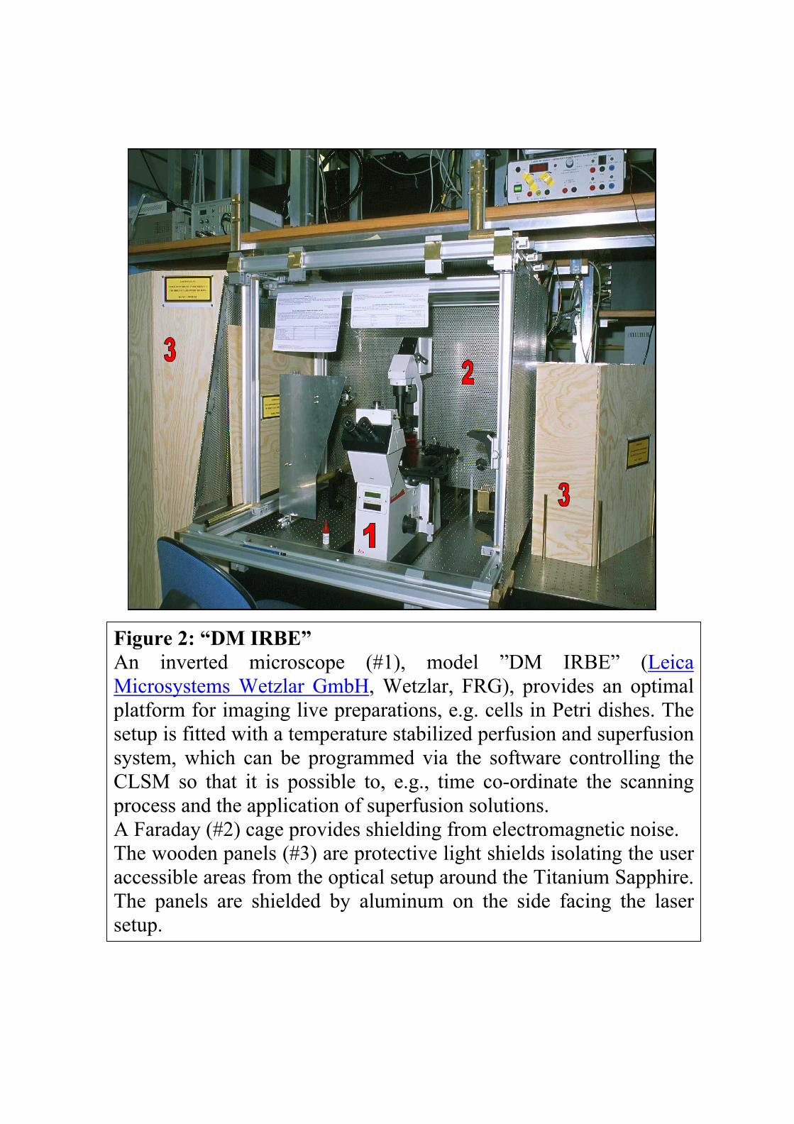
Figure 2: “DM IRBE” An inverted microscope (#1), model ”DM IRBE” (LeicaMicrosystems Wetzlar GmbH, Wetzlar, FRG), provides an optimalplatform for imaging live preparations, e.g. cells in Petri dishes. Thesetup is fitted with a temperature stabilized perfusion and superfusionsystem, which can be programmed via the software controlling theCLSM so that it is possible to, e.g., time co-ordinate the scanningprocess and the application of superfusion solutions. A Faraday (#2) cage provides shielding from electromagnetic noise. The wooden panels (#3) are protective light shields isolating the useraccessible areas from the optical setup around the Titanium Sapphire.The panels are shielded by aluminum on the side facing the lasersetup.

Figure 3: “DM LFSA” This image shows a setup including a so called ”upright fixed-stage microscope” (#1), model ”DM LFSA” (Leica Microsystems Wetzlar GmbH, Wetzlar, FRG). Microscopes of that type feature ”objective focusing mechanisms” instead of the ”stage focusing mechanisms commonly used in upright microscopes. On fixed stage microscopes, nomen est omen, the stage of the microscope needs not be moved during focusing; instead the objectives are risen or lowered. During magnification changes, the objectives move in North-South instead of East-West direction, a sine qua non for the so called “patch clamp experiments (ref. e.g. Sakmann & Neher, ed., Single-Channel Recording, Second Edition, Plenum Press, New York & London 1995). Electrical shielding is provided by means of a Faraday cage (#2), which prevents thepreparation and the on-the-stage components of the electrical amplifier units to beexposed to external electromagnetic noise. Further, in order to do patch clampexperiments, the setup has to be isolated extraordinarily well from any source ofmechanical vibrations. The state of the art optical table, model “RS 4000”, mountedon pneumatic isolators, model “I 2000” (both Newport – Micro Contrôle, Irvine,CA, USA, and Évry, France) protects against vibrations generated externally or onthe bench. Programmable electronic pulse generators (#3, specified by the author and designedand built by the staff of the local Electronics Workshop) that can be triggered fromthe electronic control unit of the confocal microscope can be used to time co-ordinate the scanning process and the electrical stimulation of cells and detection oftheir response signals by means of electronic units (#4), model “Axo Patch 1D” &“DigiData 1200” (Axon Instruments, Inc., Foster City, CA, USA) or model “SEC-05LX” & “GIA-05X” (npi electronic GmbH, Tamm, FRG). Thus it is possible toperform combined, time co-ordinated electrophysiological and fluorescenceconfocal or multi-photon laser microscopic compound experiments (ref. e.g. Helm,A microscopic setup for combined, and time coordinated electrophysiological andconfocal fluorescence microscopic experiments on neurons in living brain slices,Review of Scientific Instruments, Vol. 67, No.2, Feb. 1996, pp. 530-534)
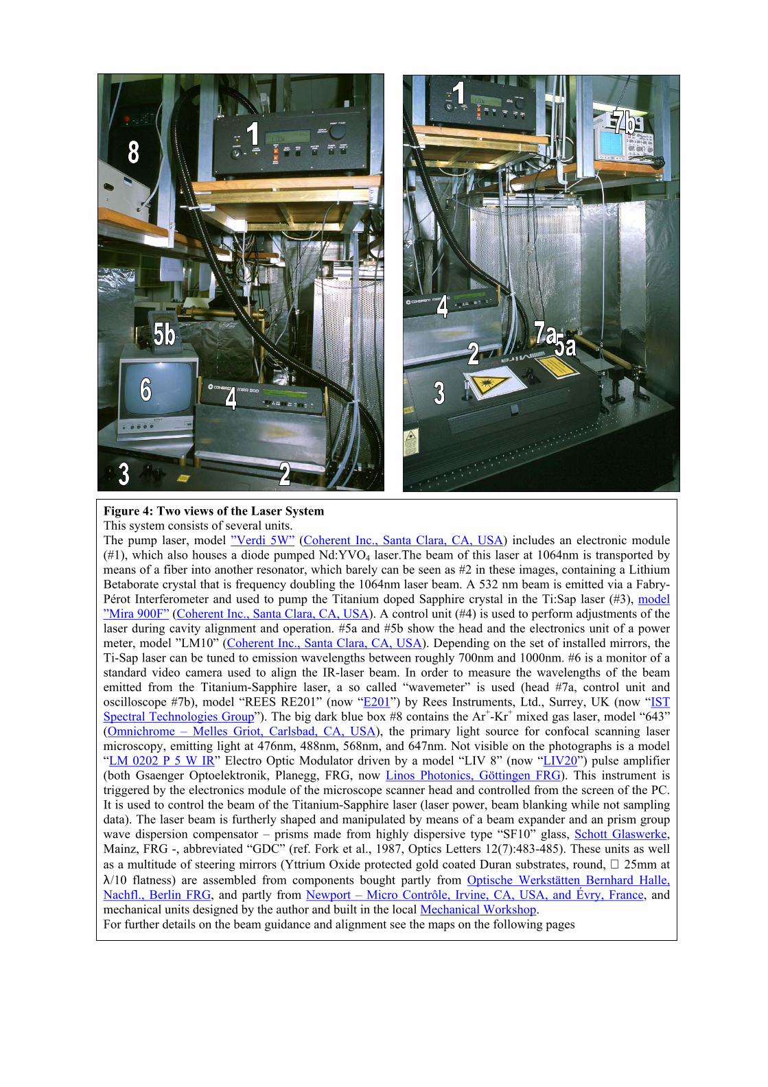
Figure 4: Two views of the Laser System This system consists of several units. The pump laser, model ”Verdi 5W” (Coherent Inc., Santa Clara, CA, USA) includes an electronic module(#1), which also houses a diode pumped Nd:YVO4 laser.The beam of this laser at 1064nm is transported bymeans of a fiber into another resonator, which barely can be seen as #2 in these images, containing a LithiumBetaborate crystal that is frequency doubling the 1064nm laser beam. A 532 nm beam is emitted via a Fabry-Pérot Interferometer and used to pump the Titanium doped Sapphire crystal in the Ti:Sap laser (#3), model”Mira 900F” (Coherent Inc., Santa Clara, CA, USA). A control unit (#4) is used to perform adjustments of thelaser during cavity alignment and operation. #5a and #5b show the head and the electronics unit of a powermeter, model ”LM10” (Coherent Inc., Santa Clara, CA, USA). Depending on the set of installed mirrors, theTi-Sap laser can be tuned to emission wavelengths between roughly 700nm and 1000nm. #6 is a monitor of astandard video camera used to align the IR-laser beam. In order to measure the wavelengths of the beamemitted from the Titanium-Sapphire laser, a so called “wavemeter” is used (head #7a, control unit andoscilloscope #7b), model “REES RE201” (now “E201”) by Rees Instruments, Ltd., Surrey, UK (now “ISTSpectral Technologies Group”). The big dark blue box #8 contains the Ar+-Kr+ mixed gas laser, model “643”(Omnichrome – Melles Griot, Carlsbad, CA, USA), the primary light source for confocal scanning lasermicroscopy, emitting light at 476nm, 488nm, 568nm, and 647nm. Not visible on the photographs is a model“LM 0202 P 5 W IR” Electro Optic Modulator driven by a model “LIV 8” (now “LIV20”) pulse amplifier(both Gsaenger Optoelektronik, Planegg, FRG, now Linos Photonics, Göttingen FRG). This instrument istriggered by the electronics module of the microscope scanner head and controlled from the screen of the PC.It is used to control the beam of the Titanium-Sapphire laser (laser power, beam blanking while not samplingdata). The laser beam is furtherly shaped and manipulated by means of a beam expander and an prism groupwave dispersion compensator – prisms made from highly dispersive type “SF10” glass, Schott Glaswerke,Mainz, FRG -, abbreviated “GDC” (ref. Fork et al., 1987, Optics Letters 12(7):483-485). These units as wellas a multitude of steering mirrors (Yttrium Oxide protected gold coated Duran substrates, round, ∅ 25mm atλ/10 flatness) are assembled from components bought partly from Optische Werkstätten Bernhard Halle,Nachfl., Berlin FRG, and partly from Newport – Micro Contrôle, Irvine, CA, USA, and Évry, France, andmechanical units designed by the author and built in the local Mechanical Workshop. For further details on the beam guidance and alignment see the maps on the following pages
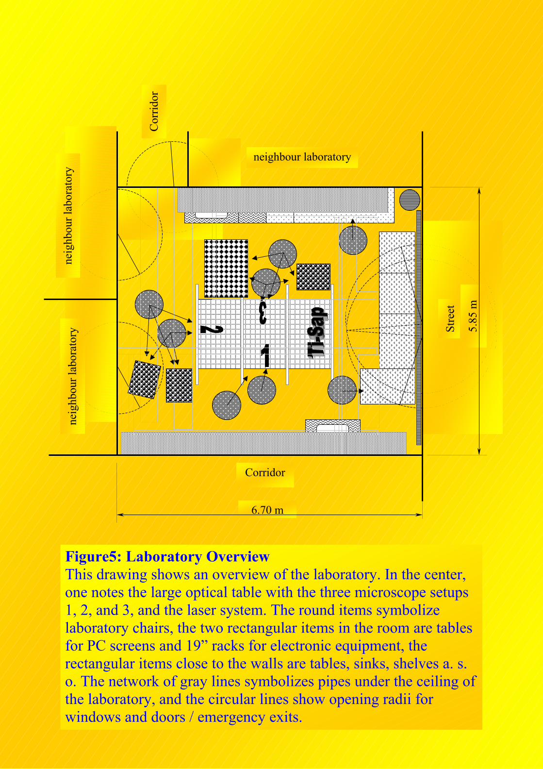
Figure5: Laboratory Overview This drawing shows an overview of the laboratory. In the center, one notes the large optical table with the three microscope setups 1, 2, and 3, and the laser system. The round items symbolize laboratory chairs, the two rectangular items in the room are tables for PC screens and 19” racks for electronic equipment, the rectangular items close to the walls are tables, sinks, shelves a. s. o. The network of gray lines symbolizes pipes under the ceiling of the laboratory, and the circular lines show opening radii for windows and doors / emergency exits.
5.85
m
Stre
et
neig
hbou
r lab
orat
ory
neig
hbou
r lab
orat
ory
neighbour laboratory
Corridor
Cor
ridor
6.70 m

Figure 6: The arrangement of items on the Optical Table The three microscopic setups can easily be recognized as well as thelasers. Besides these large items, the beam steering optics, the ElectroOptic Modulator, the Beam Expander and the Prism Group WaveDispersion Compensator are shown.
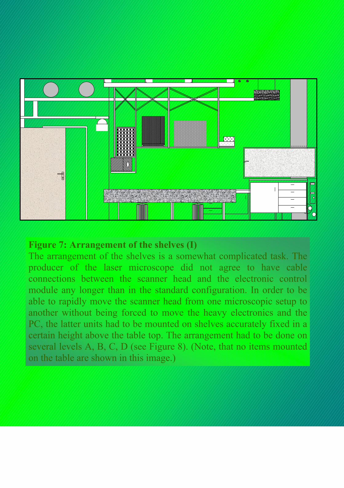
Figure 7: Arrangement of the shelves (I) The arrangement of the shelves is a somewhat complicated task. Theproducer of the laser microscope did not agree to have cableconnections between the scanner head and the electronic controlmodule any longer than in the standard configuration. In order to beable to rapidly move the scanner head from one microscopic setup toanother without being forced to move the heavy electronics and thePC, the latter units had to be mounted on shelves accurately fixed in acertain height above the table top. The arrangement had to be done onseveral levels A, B, C, D (see Figure 8). (Note, that no items mountedon the table are shown in this image.)
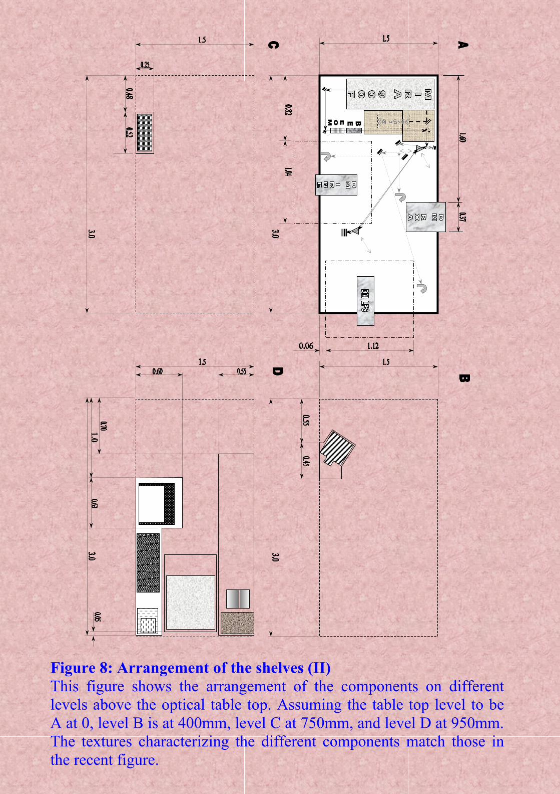
Figure 8: Arrangement of the shelves (II) This figure shows the arrangement of the components on differentlevels above the optical table top. Assuming the table top level to beA at 0, level B is at 400mm, level C at 750mm, and level D at 950mm.The textures characterizing the different components match those inthe recent figure.