kollmorgen direct drive linear motor selection guide€¦ · kollmorgen direct drive linear ddl...
TRANSCRIPT

Kollmorgen Direct Drive Linear Motor Selection Guide

K O L L M O R G E N
Kollmorgen. Every solution comes from a real understanding of OEM challenges facing machine designers and users.The ever-escalating demands of the marketplace mean increased pressure on machine designers and users at every turn. Time constraints. Demands for better performance. Having to think about the next-generation machine even before the current one is built. While expectations are enormous, budgets are not. Kollmorgen’s innovative automation and motion solutions and broad range of quality products help engineers not only overcome these challenges but also build truly differentiated machines.
Because motion matters, it’s our focus. Motion can distinctly differentiate a machine and deliver a marketplace advantage by improving its performance. This translates to overall increased efficiency on the factory floor. Perfectly deployed machine motion can make your customer’s machine more reliable and efficient, enhance accuracy and improve operator safety. Motion also represents endless possibilities for innovation. We’ve always understood this potential, and thus, have kept motion at our core, relentlessly developing products that offer precision control of speed, accuracy and position in machines that rely on complex motion.
K O L L M O R G E N

w w w. k o l l m o r g e n . c o m
Table of ContentsuDirect Drive Linear (DDL) Motor 4
uDirect Drive Linear Motor Summary 9
uDDL Ironless - Non-cooled Data and Dimensions
IL06 Series 12
IL12 Series 14
IL18 Series 16
IL24 Series 20
uIronless Magnet Ways 22
uDDL Ironcore Data and Dimensions
ICD05 Series 26
ICD10 Series 28
uICD Magnet Ways 30
uDDL Ironcore - Non-cooled Data and Dimensions
IC11 Series 34
IC22 Series 36
IC33 Series 38
IC44 Series 40
uDDL Ironcore - Water-cooled Data and Dimensions
IC11 Series 48
IC22 Series 50
IC33 Series 54
IC44 Series 58
uIroncore Magnet Ways 62
uWiring and Output 64
uHigh Flex Cable Sets 66
uApplication Sizing 67
uModel Nomenclature 70
K O L L M O R G E N D I R E C T D R I V E L I N E A R M O T O R S E L E C T I O N G U I D E
Removing the Barriers of Design, Sourcing, and Time At Kollmorgen, we know that OEM engineers can achieve a lot more when obstacles aren’t in the way. So, we knock them down in three important ways:
Integrating Standard and Custom ProductsThe optimal solution is often not clear-cut. Our application expertise allows us to modify standard products or develop totally custom solutions across our whole product portfolio so that designs can take flight.
Providing Motion Solutions, Not Just ComponentsAs companies reduce their supplier base and have less engineering manpower, they need a total system supplier with a wide range of integrated solutions. Kollmorgen is in full response mode with complete solutions that combine programming software, engineering services and best-in-class motion components.
Global FootprintWith direct sales, engineering support, manufacturing facilities, and distributors across North America, Europe, Middle East, and Asia, we’re close to OEMs worldwide. Our proximity helps speed delivery and lend support where and when they’re needed.
Financial and Operational Stability Kollmorgen is part of Danaher Corporation, our $13B parent company. A key driver in the growth of all Danaher divisions is the Danaher Business System, which relies on the principle of “kaizen” – or continuous improvement. Using world-class tools, cross-disciplinary teams of exceptional people evaluate processes and develop plans that result in superior performance.

K O L L M O R G E N
DI
RE
CT
D
RI
VE
L
IN
EA
R
MO
TO
R Direct Drive Linear MotorOur direct drive linear motor series provide new dimension in performance with high throughput, accuracy, and zero maintenance. The product line are frameless, permanent magnet, three phase, brushless servomotors. The product line consists of two fundamental constructions, Ironless (slotless) and Ironcore. Ironless motors have no attractive force between the framless components and zero cogging for the ultra smooth motion. Ironcore motors provide the highest force per frame size. The feature a patented anti-cogging design which yields extremely smooth operation.

5w w w. k o l l m o r g e n . c o m
DI
RE
CT
D
RI
VE
L
IN
EA
R
MO
TO
R
The Benefits of Direct Drive Linear Motor
• Zero Maintenance with Greater Accuracy and Higher Bandwidth • Smoother velocity and reduced audible noise
• Power transmission without backlash
• Transmission elements such as couplings, toothed belts,
ball/lead screws, rack & pinions, and other fitted components
can be eliminated
• No gears or screws, no lubrication required
• Improved machine reliability
• Wide Range of Sizes and Force to Cover any Linear Application • Increased performance for the entire system
• Flat, compact drive solution
• Easily mix / match motors and drives
• Real-life acceleration up to 10 G
• Simplified, High Force Permanent Magnet Design • Higher bandwidth and faster response than ball/lead screws or
rack & pinion solutions
• Rapid indexing of heavy loads with peak force up to
12,500 N (2,800 lb)
• Reduced audible noise, fewer parts and lower cost of ownership
• More compact machine design

K O L L M O R G E N 6
DI
RE
CT
D
RI
VE
L
IN
EA
R
MO
TO
R
OV
ER
VI
EW
Direct Drive Linear Motor OverviewKollmorgen Direct Drive Linear DDL Motor Series
Kollmorgen supplied its first linear motors in the late 1970’s for use
in precision X-Y tables and coating systems. These were brush DC
motors using the Kollmorgen patented push-through commutator bar
method. This led to development in the early 1980’s of the brushless
versions of the linear motor which were used in film processing
applications where smooth, high stiffness, linear motion was
required. During the past 30 years, advances in permanent magnet
material, power semiconductors, and microprocessor technology
have been the enablers for increased performance and lower costs
for linear motors.
DDL motors series comply with the Low Voltage Directive 2006/95/EG
for installation in a machine. Safety depends upon installing and con-
figuring motor per the manufacturer’s recommendations. The machine
in which this product is to be installed must conform to the provisions
of EC directive 2006/95/EG. The installer is responsible for ensuring
that the end product complies with all the relevant laws in the country
where the equipment is installed.
Ironcore Motor
Ironless Motor
Standard Product Features
Ironless:• Peak force 60 to 1600 N• Continuous force 21 to 450 N• Zero cogging• Zero attractive force• Smooth motion for speed as low as 1 micron/second
(0.00004 in/sec)• Low mass coil assembly for high acceleration
Ironcore:• Peak force IC series: 320 to 8407 N• Continuous force IC series: 144 to 6916 N• Peak force ICD series: 165 to 1099 N• Continuous force ICD series: 57.0 to 315 N• Patented anti-cogging technique for minimal cogging
without magnet skewing• High motor constant (Km)• High force density• ICD series advantage: – Very low profile – Low attraction force – Suitable to replace many Ironless applications
All Motors:• Zero contact, zero maintenance, brushless design• 3 phase sinusoidal commutation• Peak accelerations easily above 10 G• High position accuracy and resolution• Very low settling time• Low thermal losses• Modular magnet design
Standard Options:• Hall effect feedback• Thermal protection – Thermistor – Thermostat (Ironcore)• Supplemental air or water cooling (Ironcore)• Cable options• Magnet way covers for easy cleaning (Ironcore)• Factory Mutual (FM) approved, hazardous environment

7w w w. k o l l m o r g e n . c o m
DI
RE
CT
D
RI
VE
L
IN
EA
R
MO
TO
R
OV
ER
VI
EW
The two primary components of permanent magnet brushless rotary motors are the stator (primary coils) and the rotor (secondary or rotating magnets). In brushless linear motors the rotor is rolled out flat to become the magnet track (also called the magnet way). The primary coils of the rotary motor are rolled out flat to become the coil assembly (also sometimes called the slider).
In most brushless linear motor applications it is typical for the magnet way to be stationary and the coil assembly to be in motion, because of the relative masses of the two components. But it is also perfectly acceptable and sometimes advantageous to reverse this arrangement. The basic electromagnetic operating principles are the same in either case and are identical to those of a rotary motor.
Direct Drive Linear Motor Options
Two types of linear motors are available, Ironcore and Ironless. Each one provides characteristics and features that are optimal depending upon the application. Ironcore motors have coils wound on silicon steel laminations, to maximize the generated force, with a single sided magnet way.
Using a patented electromagnetic design, DDL linear motors have the highest rated force per size, a high Km motor constant (equals low thermal losses), and low cogging forces without the need for skewing of the magnets. The high thrust forces possible with these motors make them ideal for accelerating and moving high masses, and maintaining stiffness during machining or process forces. Ironless motors have no iron, or slots for the coils to be wound on.
Therefore, these motors have zero cogging, a very light mass, and absolutely no attractive forces between the coil assembly and the magnet way. These characteristics are ideal for applications requiring very low bearing friction, high acceleration of lighter loads, and for maximizing constant velocity, even at ultra low speeds. The modular magnet ways consists of a double row of magnets to maximize the generated thrust force and to providea flux return path for the magnetic circuit.
Feedback Types
All brushless motors require feedback for commutation. For a linear motor, commutation feedback can also be accomplished with a variety of methods. Digital or linear Hall effect devices are available from Kollmorgen for the DDL motor series which allow the drive electronics to commutate the linear motors in a manner identical to rotary motors.
For exceptionally smooth motion requirements, sinusoidal drive electronics using digital Hall effects, provide sinusoidal drive currents to the motor for the best constant force and velocity performance. As an alternative, it is typical for linear motor applications to have a linear encoder present in the system for position feedback. It is increasingly common today for drive amplifiers to derive the necessary commutation information directly from this linear encoder, either with or without supplemental digital Hall effect devices on startup. Other types of feedback used on linear motor applications include linear Inductosyns, laser interferometers, and LVDT.
Slider
BasePermanentMagnetsRotary Motor Linear Motor
Air Gap
Rotor
Windings
Stator
SN
Rotary Motor Rolled Out Flat
Our Direct Dirve Linear (DDL) motor series are frameless permanent magnet, three phase brushless servomotors. Fundamentally, a linear motor is a rotary motor that is rolled out flat.

K O L L M O R G E N 8
DI
RE
CT
D
RI
VE
L
IN
EA
R
MO
TO
R
OV
ER
VI
EW
Direct Drive Linear Motor OverviewAdvantages
Wide Speed RangeSince the frameless parts of the linear motor are non-contact, and no limitations of a mechanical transmission are present, both very high speeds and very low speeds are easily obtainable. Speeds are truly not limited by the motor. Instead, by eliminating the mechanical transmission, speed becomes limited by other elements in the system such as the linear bearings, and the achievable bandwidth from any feedback devices. Application speeds of greater than 5 meters per second or less than 1 micron per second are typically achievable. In comparison, mechanical transmissions such as ball screws are commonly limited to linear speeds of 0.5 to 0.7 meters per second because of resonances and wear. In addition to a wide speed range, linear motors, both ironcore and ironless, have excellent constant velocity characteristics, typically better than ± 0.01% speed variation.
High System DynamicsIn addition to high speed capability, direct drive linear motors are capable of very high accelerations. Limited only by the system bearings, accelerations of 3 to 5 G are quite typical for the larger motors and accelerations exceeding 10 G are easily achievable for smaller motors.
Easy Selection process:1. Determine peak and continuous force required for your applications (see our applications section on pages 67-69 or use MOTIONEERING, our online sizing and selection software tool)2. Use the motor selection guide on pages 9-11 to choose your motor3. Refer to the appropriate pages in the data publication for technical
details4. Build model number for ordering using pages 70-71
Smooth Operation and Positional AccuracyBoth ironless and ironcore motors exhibit very smooth motion profiles due to the inherent motor design of Kollmorgen's DDL series. Cogging, which is a component of force, is greatly reduced in the ironcore designs and is zero in the ironless designs. As a result, these direct drive linear motors provide very low force and velocity ripple for ultra smooth motion. Positioning accuracies are limited only by the feedback resolution,and sub-micron resolutions are commonly achievable.
Unlimited TravelWith the DDL motor series, magnet ways are made in 5 modular sections: 64mm, 128mm, 256mm, 512mm and 1024mm long. Each module can be added in unlimited numbers to any other module to allow for unlimited travel. Whether the travel required is 1mm or 100 meters the DDL series can accommodate the need.
No Wear or MaintenanceLinear motors have few components, therefore the need for ball screw components such as nuts, bearing blocks, couplings, motor mounts and the need to maintain these components have been eliminated. Very long life and clean operation, with no lubrication or maintenance of these parts are the result.
Integration of Components is Much SimplerFrameless linear motors require much fewer components than rotary motors with mechanical transmissions. A 0.8mm airgap for the ironcore design and 0.5mm airgap for the ironless design is the only alignment of the frameless linear motor components that is necessary. No critical alignments are required as with ball screws. Straightness of travel as provided by the system linear bearings is more than sufficient for the Kollmorgen linear motors.
Typical Applications for Linear Motors Include:
Machine Tool Measurement/inspectionDrilling Coordinate measurement machinesMilling Electronic assemblyGrinding Pick-and-place machinesLaser cutting Component insertionCam grinding Screen printersSemiconductor Adhesive dispensersWafer handling process PC board inspection, drillingWafer-inspection Wafer slicing Other applications include: Tab bonding Flight SimulatorsWire bonding Acceleration sledsIon implantation CatapultLithography G-Force measurement Textile Carpet tufting

9w w w. k o l l m o r g e n . c o m
DI
RE
CT
D
RI
VE
L
IN
EA
R
MO
TO
R
SU
MM
AR
Y
0 100
200
300
400
500
600
700
800
900
1000
1100
1200
1300
1400
1500
1600
IL06-030
IL06-050
IL06-075
IL06-100
IL12-030
IL12-050
IL12-075
IL12-100
IL18-030
IL18-050
IL18-075
IL18-100
IL24-030
IL24-050
IL24-075
IL24-100
Mot
or T
ype
0 100
200
300
400
500
600
700
800
900
1000
1100
1200
1300
1400
1500
1600
ICD05-030
ICD05-050
ICD05-075
ICD05-100
ICD10-030
ICD10-050
ICD10-075
ICD10-100
MaxContinuous
Force
PeakForce
SeePageNo.
N (lbf) N (lbf)57.0 12.8 165 37.1 32
87.0 19.6 295 66.3 32
125 28.1 441 99.1 32
157 35.3 588 132 32
104 23.4 330 74.2 34
171 38.4 550 124 34
246 55.3 824 185 34
315 70.8 1099 247 34
Ironcore Linear Motors
Mot
or T
ype
Direct Drive Linear Motor SummaryIronless Linear Motors
MaxContinuous
Force
PeakForce
SeePageNo.
N (lbf) N (lbf)30.3 6.81 120 27.0 18
49.7 11.2 200 45.0 18
67.6 15.2 300 67.4 18
82.8 18.6 400 89.9 18
62.1 14.0 240 54.0 20
88.4 19.9 400 89.9 20
119 26.8 600 135 20
148 33.3 800 180 20
92.1 20.7 360 80.9 22
131 29.4 600 135 22
173 38.9 900 202 23
211 47.4 1200 270 23
109 24.5 480 108 26
155 34.8 800 180 26
211 47.4 1200 270 26
262 58.9 1600 360 26
Continuous Force N Peak Force N
Continuous Force NPeak Force N
(Non-Cooled)
Newtons
Newtons

K O L L M O R G E N 10
DI
RE
CT
D
RI
VE
L
IN
EA
R
MO
TO
R
SU
MM
AR
Y
Direct Drive Linear Motor Summary0 10
00
2000
3000
4000
5000
6000
7000
8000
9000
1000
0
IC11-030
IC11-050
IC11-075
IC11-100
IC11-150
IC11-200
IC22-030
IC22-050
IC22-075
IC22-100
IC22-150
IC22-200
Ironcore Linear Motors
Mot
or T
ype
Newtons
IC33-030
IC33-050
IC33-075
IC33-100
IC33-150
IC33-200
IC44-030
IC44-050
IC44-075
IC44-100
IC44-150
IC44-200
Continuous Force NPeak Force N
(Non-Cooled)
MaxContinuous
Force
PeakForce
SeePageNo.
N (lbf) N (lbf)144 32.4 320 71.9 40
263 59.1 533 120 40
413 92.8 800 180 40
574 129 1067 240 40
861 194 1600 360 40
1197 269 2135 480 40
280 62.9 624 140 42
526 118 1039 234 42
825 185 1558 350 42
1148 258 2077 467 43
1723 387 3117 701 43
2393 538 4156 934 43
431 96.9 944 212 46
789 177 1572 353 46
1238 278 2358 530 46
1722 387 3144 707 47
2583 581 4716 1060 47
3590 807 6291 1414 47
560 126 1259 283 50
1053 237 2096 471 50
1651 371 3144 707 50
2296 516 4192 942 51
3445 774 6289 1414 51
4786 1076 8388 1885 51

11w w w. k o l l m o r g e n . c o m
DI
RE
CT
D
RI
VE
L
IN
EA
R
MO
TO
R
SU
MM
AR
Y
0 1000
2000
3000
4000
5000
6000
7000
8000
9000
1000
0
IC11-030
IC11-050
IC11-075
IC11-100
IC11-150
IC11-200
IC22-030
IC22-050
IC22-075
IC22-100
IC22-150
IC22-200
Ironcore Linear Motors
Mot
or T
ype
Newtons
IC33-030
IC33-050
IC33-075
IC33-100
IC33-150
IC33-200
IC44-030
IC44-050
IC44-075
IC44-100
IC44-150
IC44-200
Continuous Force NPeak Force N
(Water-Cooled)
MaxContinuous
Force
PeakForce
SeePageNo.
N (lbf) N (lbf)254 57.1 315 70.8 54
432 97.1 525 118 54
649 146 798 179 54
864 194 1051 236 54
1285 289 1576 354 54
1712 385 2102 473 54
519 117 630 142 56
864 194 1051 236 56
1284 287 1576 354 56
1715 386 2106 473 57
2566 577 3152 709 57
3458 777 4204 945 57
769 173 945 212 60
1283 288 1575 354 60
1926 433 2365 532 60
2593 583 3152 709 61
3849 865 4724 1063 61
5135 1154 6306 1418 61
1036 233 1260 283 64
1711 385 2101 472 64
2568 577 3154 709 64
3457 777 4202 945 65
5133 1154 6303 1417 65
6916 1555 8407 1890 65

K O L L M O R G E N 12
IL
06
P
ER
FO
RM
AN
CE
D
AT
A
IL06 Performance Data
Rated Perfomance Symbol Units IL06-030 IL06-050 IL06-075 IL06-100
Peak Force FpN
lbf
120 200 300 400
27 45 68 90
Continuous Force @ Tmax (1) FcN
lbf
30.3 49.7 67.6 82.8
6.81 11.2 15.2 18.6
Motor Constant Km N√W 5.6 8.0 10.2 12.1
Electrical Specifications (2)Winding Code A1 A4 A1 A4 A1 A4 A1 A4
Peak Current lp Arms 7.1 14.2 7.0 14.0 7.0 14.0 7.0 14.0
Continuous Current @Tmax lc Arms 1.8 3.6 1.7 3.5 1.6 3.2 1.5 2.9
Electrical Resistance @ 25°C±10% Rm Ohms L-L 6.1 1.5 8.6 2.2 11.7 2.9 14.7 3.7
Electrical Inductance ±20% L mH L-L 1.3 0.33 3.00 0.75 5.00 1.25 7.00 1.75
Back EMF Constant
@ 25°C±10%Ke
Vpeak/m/s L-L 13.7 6.9 23.3 11.6 34.9 17.5 46.5 23.3
Vpeak/in/sec L-L 0.35 0.17 0.59 0.30 0.89 0.44 1.18 0.59
Force Constant @ 25°C±10% kfN/Arms 16.8 8.4 28.5 14.3 42.8 21.4 57.0 28.5
lbf/Arms 3.8 1.9 6.4 3.2 9.6 4.8 12.8 6.4
Mechanical Specifications
Coil Assembly Mass ±15% Mckg 0.27 0.32 0.38 0.45
lbs 0.6 0.7 0.8 1.0
Magnetic Way TypeMW MW MW075 MW075
030 030L 050 050L
Magnetic Way Mass ±15% Mwkg/m 9.4 7.3 12.2 10.2 18.9 27.3
lb/in 0.51 .040 0.68 0.56 1.05 1.51
Figures of Merit and Additional DataElectrical Time Constant Te ms 0.21 0.35 0.43 0.48
Max.Theoretical Acceleration (3) Amax g’s 45.2 63.6 80.6 90.7
Magnetic Attraction FakN 0 0 0 0
lbf 0 0 0 0
Thermal Resistance (4)
(Coils to External Structure)Rth °C/Watt 1.61 1.26 1.04 0.87
Max. Allowable Coil Temp. (4) Tmax °C 130 130 130 130
Notes:1. The motor continuous rated force is measured with the motor coils achieving the motor maximum allowable temperature Tmax.2. Alternate windings can be made available. Please consult the Kollmorgen Customer Support for design options.3. Maximum theoretical acceleration is based on the motors peak force and the motor mass alone. Limitations due to such factors as the additional mass of the load, the bearing type and design, the shock rating of the feedback, the peak current available from the amplifier etc. must be considered to determine the achievable acceleration in each application.4. Please see our application sizing pages in the back of this guide for more details on sizing and thermal considerations.
Ironless Non-Cooled Motors Series

13w w w. k o l l m o r g e n . c o m
IL
06
O
UT
LI
NE
D
RA
WI
NG
S
IL06 Outline Drawings
15.4 (.606)BOTHSIDES
10.8(.427)
40.0(1.575)2 PL.BOTHSIDES
"B"
FOR MO TO R CABLEAND HALL EFFEC T MTG.SEE DR AWING BELO W
4.4(.173)
CO IL TO MAGNET AIRGAP0.74 REF TYP. FO R 030, -050
1.12 REF TYP. FO R -075 AND -100
110.8 (4.362) M AX.
35.3(1.391)
40.0(1.575)
4.0(.157)
3.9(.152)
16.7(.657)
24.4(.961)
4.5(.176)
10.0(.394)
M5 X 0.8 X 5 DP .6 PL., 3 PER SIDE
M5 X 0.8 X 5 DP .4 PL.
1.2 .05(.048 .002)
CLEAR ANCE-SET UP D IM.
CO IL ASSEMBLY
MAGNET WAY REF.
17.0(.669)
"A"
"T"
Termination and Hall Effect Options
STANDARD LENGTH,SEE TABLE
THERMAL PROTECTION CONNECTOR: 2 PIN - M ALE C ONNEC TO R FREE HANGING RECEPT ACLE MOLEX P/N 43025-0200 2 FEM ALE TERMINALS MOLEX P/N 43030-0010
MOTOR CONNECTOR: POSITR ONIC P/N: CBD3W3M0000Z 3 PIN M ALE , SHELL SIZE 2MALE CO NTACTS: POSITR ONIC P/N: MS40--D 3 REMOV ABLE M ALE CONT ACTS, SIZE 8
12
321
PIN 1
PIN 1
PIN 1
PIN 9
PIN 5
21.0(.827)MAX.
#4-40 JA CKNUT (2)(REMOV ABLE FOR BULKHEAD MOUNTING)
HALL EFFEC T ASSEMBL Y
CO IL ASSEMBLY REF
HALL EFFEC T CONNECTOR OPTION: POSITR ONIC P/N: MD9M2000Z 9 PIN, M ALEMATING CONNECTOR REFERENCE: POSITR ONIC P/N: MD9F2000X
SEE WIRE TABLE, PAGE 70
MATING CONNECTOR REFERENCE: POSITR ONIC P/N: CBD3W3F0000X 3 FEM ALE SOCKE TS, SO LDER TYPE, SIZE 8, POSITR ONIC P/N: FS40--D
SEE WIRE TABLE, PAGE 70
MATING CONNECTOR REFERENCE: MOLEX " MICR O -F IT 3.0" PL UG: 43020-0201 MALE TERMINALS: 43031-0010
SEE WIRE TABLE, PAGE 70
4.0 .3(.157 .012)
STANDARD LENGTH,SEE TABLE
CO IL ASSEMBLY REF
6.8 .3(.268 .012)
7.7 .3(.303 .012)
MOTOR CABLE
OPTIONAL HALL EFFEC T AS SHOWN, MOUNTING HOLESM3 X 6.3 (.25) MIN. DP . 2 PL.
THERMAL
MOTOR
HALLEFFEC T
HALL EFFEC T MASSW/P* C ONNEC TO R: .05KG (.11 LB) MAXW/C* C ABLE: .03K G (.06 LB) M AX
12.2 .3(.480 .012)
+_+_
+_+_
+_+_
+_+_
Motor CoilCoil Width Typ. Assy. Width Typ. Assy. Width
"A" +.7 (0.027) -.3 (0.012) "B" ±.6 (.024) "T" ±.4 (.016)
IL06-030 57.30 (2.256) 78.50 (3.091) 25.40 (1.000)IL06-030 L 57.30 (2.256) 67.30 (2.650) 25.40 (1.000)IL06-050 77.30 (3.043) 98.50 (3.878) 25.40 (1.000)
IL06-050 L 77.30 (3.043) 87.30 (3.437) 25.40 (1.000)IL06-075 102.30 (4.028) 123.50 (4.862) 30.00 (1.181)IL06-100 127.30 (5.012) 148.50 (5.846) 34.00 (1.339)
Notes:1. Dimensions in mm (inches)2. Tolerances unless otherwise specified: no decimal place ±0.8 (0.3) X decimal place ±0.1 (.004) XX decimal place ±0.05 (0.002)
Connector OptionConnector Length
P1 400 (16)P2 200 (8)P3 100 (4)P4 1200 (48)
Flying Lead OptionLeads Length
C1 400 (16)C2 200 (8)C3 100 (4)C4 1200 (48)
Note:Cables exiting motor and hall effects are not dynamic flex cables. For high life flex extension cables, see page 72
Ironless Non-Cooled Motors Series

K O L L M O R G E N 14
IL
12
P
ER
FO
RM
AN
CE
D
AT
A
IL12 Performance Data
Rated Perfomance Symbol Units IL12-030 IL12-050 IL12-075 IL12-100
Peak Force FpN 240 400 600 800
lbf 54 90 135 180
Continuous Force @ Tmax (1) FcN 62.1 88.4 119 148
lbf 14.0 19.9 26.8 33.3
Motor Constant @ 25°C Km N√W 7.8 11.3 14.5 17.2
Electrical Specifications (2)Winding Code A1 A2 A4 A1 A2 A4 A1 A2 A4 A2 A4
Peak Current lp Arms 7.1 14.2 28.5 7.0 14.0 28.1 7.0 14.0 28.1 14.0 28.1
Continuous Current @Tmax lc Arms 1.8 3.7 7.4 1.6 3.1 6.2 1.4 2.8 5.6 2.6 5.2
Elextrical Resistance
@ 25°C±10%Rm Ohms L-L 12.2 3.1 0.8 17.2 4.3 1.1 23.3 5.8 1.5 7.4 1.8
Electrical Inductance ±20% L mH L-L 2.60 0.65 0.16 6.00 1.5 0.38 10.0 2.5 0.63 3.5 0.88
Back EMF Constant
@ 25°C±10%Ke
Vpeak/m/s L-L 27.5 13.8 6.9 46.5 23.3 11.6 69.8 34.9 17.5 46.5 23.3
Vpeak/in/sec L-L 0.70 0.35 0.17 1.18 0.59 0.30 1.77 0.89 0.44 1.18 0.59
Force Constant
@ 25°C±10%Kf
N/Arms 33.7 16.9 8.4 57.0 28.5 14.3 85.5 42.8 21.4 57.0 28.5
lbf/Arms 7.6 3.8 1.9 12.8 6.4 3.2 19.2 9.6 4.8 12.8 6.4
Mechanical Specifications
Coil Assembly Mass ±15% Mckg 0.42 0.52 0.65 0.77
lbs 0.9 1.1 1.4 1.7
Magnetic Way TypeMW MW MW075 MW100
030 030L 050 050L
Magnetic Way Mass ±15% Mwkg/m 9.4 7.3 12.2 10.2 18.9 27.3
lb/in 0.51 0.40 0.68 0.56 1.05 1.51
Figures of Merit and Additional DataElectrical Time Constant Te ms 0.21 0.35 0.43 0.48
Max.Theoretical Acceleration (3) Amax g’s 58.2 78.4 94.1 106
Magnetic Attraction FakN 0 0 0 0
lbf 0 0 0 0
Thermal Resistance (4)
(coils to external structure)Rth °C/Watt 0.804 0.629 0.519 0.433
Max. Allowable Coil Temp. (4) Tmax °C 130 130 130 130
Notes:1. The motor continuous rated force is measured with the motor coils achieving the motor maximum allowable temperature Tmax.2. Alternate windings can be made available. Please consult the Kollmorgen Customer Support for design options.3. Maximum theoretical acceleration is based on the motors peak force and the motor mass alone. Limitations due to such factors as the additional mass of the load, the bearing type and design, the shock rating of the feedback, the peak current available from the amplifier etc. must be considered to determine the achievable acceleration in each application.4. Please see our application sizing pages in the back of this guide for more details on sizing and thermal considerations.
Ironless Non-Cooled Motors Series

15w w w. k o l l m o r g e n . c o m
IL
12
O
UT
LI
NE
D
RA
WI
NG
S
IL12 Outline Drawings
Learn
23.4(.921)
40.0(1.575)4 PL.
206.8(8.142)MAX.
43.4(1.709)
40.0(1.575)3 PL.
4.5(.176)
10.8(.427)
"B"
4.4(.173)
24.4(.961)
CO IL ASSEMBLY
Magnet WayREF.
17.0(.669)
4.0(.157)
3.9(.152)
16.7(.657)
M5 X 0.8 X 5 DP .10 PL., 5 PER SIDE
M5 X 0.8 X 5 DP . 8 PL.
"A"
10.0(.394)
"T"
BOTHSIDES
BOTHSIDES
1.2 .05(.048 .002)
CLEAR ANCE-SET UP D IM.
FOR MO TO R CABLEAND HALL EFFEC T MTG.SEE DR AWING BELO W
CO IL TO MAGNET AIRGAP0.74 REF TYP. FO R 030, -050
1.12 REF TYP. FO R -075 AND -100
STANDARD LENGTH,SEE TABLE
THERMAL PROTECTION CONNECTOR: 2 PIN - M ALE C ONNEC TO R FREE HANGING RECEPT ACLE MOLEX P/N 43025-0200 2 FEM ALE TERMINALS MOLEX P/N 43030-0010
MOTOR CONNECTOR: POSITR ONIC P/N: CBD3W3M0000Z 3 PIN M ALE , SHELL SIZE 2MALE CO NTACTS: POSITR ONIC P/N: MS40--D 3 REMOV ABLE M ALE CONT ACTS, SIZE 8
12
321
PIN 1
PIN 1
PIN 1
PIN 9
PIN 5
21.0(.827)MAX.
#4-40 JA CKNUT (2)(REMOV ABLE FOR BULKHEAD MOUNTING)
HALL EFFEC T ASSEMBL Y
CO IL ASSEMBLY REF
HALL EFFEC T CONNECTOR OPTION: POSITR ONIC P/N: MD9M2000Z 9 PIN, M ALEMATING CONNECTOR REFERENCE: POSITR ONIC P/N: MD9F2000X
SEE WIRE TABLE, PAGE 70
MATING CONNECTOR REFERENCE: POSITR ONIC P/N: CBD3W3F0000X 3 FEM ALE SOCKE TS, SO LDER TYPE, SIZE 8, POSITR ONIC P/N: FS40--D
SEE WIRE TABLE, PAGE 70
MATING CONNECTOR REFERENCE: MOLEX " MICR O -F IT 3.0" PL UG: 43020-0201 MALE TERMINALS: 43031-0010
SEE WIRE TABLE, PAGE 70
4.0 .3(.157 .012)
STANDARD LENGTH,SEE TABLE
CO IL ASSEMBLY REF
6.8 .3(.268 .012)
7.7 .3(.303 .012)
MOTOR CABLE
OPTIONAL HALL EFFEC T AS SHOWN, MOUNTING HOLESM3 X 6.3 (.25) MIN. DP . 2 PL.
THERMAL
MOTOR
HALLEFFEC T
HALL EFFEC T MASSW/P* C ONNEC TO R: .05KG (.11 LB) MAXW/C* C ABLE: .03K G (.06 LB) M AX
12.2 .3(.480 .012)
+_+_
+_+_
+_+_
+_+_
Termination and Hall Effect Options
Notes:1. Dimensions in mm (inches)2. Tolerances unless otherwise specified: no decimal place ±0.8 (0.3) X decimal place ±0.1 (.004) XX decimal place ±0.05 (0.002)
Motor CoilCoil Width Typ. Assy. Width Typ. Assy. Width
"A" +.7 (0.027) -.3 (0.012) "B" ±.6 (.024) "T" ±.4 (.016)
IL12-030 57.30 (2.256) 78.50 (3.091) 25.40 (1.000) IL12-030 L 57.30 (2.256) 67.30 (2.650) 25.40 (1.000) IL12-050 77.30 (3.043) 98.50 (3.878) 25.40 (1.000)
IL12-050 L 77.30 (3.043) 87.30 (3.437) 25.40 (1.000) IL12-075 102.30 (4.028) 123.50 (4.862) 30.00 (1.181) IL12-100 127.30 (5.012) 148.50 (5.846) 34.00 (1.339)
Ironless Non-Cooled Motors Series
Connector OptionConnector Length
P1 400 (16)P2 200 (8)P3 100 (4)P4 1200 (48)
Flying Lead OptionLeads Length
C1 400 (16)C2 200 (8)C3 100 (4)C4 1200 (48)
Note:Cables exiting motor and hall effects are not dynamic flex cables. For high life flex extension cables, see page 72

K O L L M O R G E N 16
IL
18
P
ER
FO
RM
AN
CE
D
AT
A
IL18 Performance Data
Rated Perfomance Symbol Units IL18-030 IL18-050
Peak Force FpN 360 600
lbf 81 135
Continuous Force @ Tmax (1) FcN 92.1 131
lbf 20.7 29.4
Motor Constant @ 25°C Km N√W 9.7 13.8
Electrical Specifications (2)Winding Code A1 A2 A3 A4 A1 A2 A3 A4
Peak Current lp Arms 7.1 14.3 21.4 42.8 7.0 14.0 21.0 42.1
Continuous Current @Tmax lc Arms 1.8 3.6 5.5 11.0 1.5 3.1 4.6 9.2
Elextrical Resistance
@ 25°C±10%Rm Ohms L-L 18.2 4.6 2.0 0.5 25.7 6.4 2.9 0.7
Electrical Inductance ±20% L mH L-L 3.8 0.95 0.42 0.11 9.00 2.25 1.00 0.25
Back EMF Constant
@ 25°C±10%Ke
Vpeak/m/s L-L 41.2 20.6 13.7 6.9 69.8 34.9 23.3 11.6
Vpeak/in/sec L-L 1.05 0.52 0.35 0.17 1.77 0.89 0.59 0.30
Force Constant @ 25°C±10% KfN/Arms 50.5 25.3 16.8 8.4 85.5 42.8 28.5 14.3
lbf/Arms 11.4 5.7 3.8 1.9 19.2 9.6 6.4 3.2
Mechanical Specifications
Coil Assembly Mass ±15% Mckg 0.57 0.72
lbs 1.3 1.6
Magnetic Way TypeMW MW
030 030L 050 050L
Magnetic Way Mass ±15% Mwkg/m 9.4 7.3 12.2 10.2
lb/in 0.51 0.40 0.68 0.56
Figures of Merit and Additional DataElectrical Time Constant Te ms 0.21 0.35
Max.Theoretical Acceleration (3) Amax g’s 64.5 84.9
Magnetic Attraction FakN 0 0
lbf 0 0
Thermal Resistance (4)
(coils to external structure)Rth °C/Watt 0.536 0.419
Max. Allowable Coil Temp. (4) Tmax °C 130 130
Notes:1. The motor continuous rated force is measured with the motor coils achieving the motor maximum allowable temperature Tmax.2. Alternate windings can be made available. Please consult the Kollmorgen Customer Support for design options.3. Maximum theoretical acceleration is based on the motors peak force and the motor mass alone. Limitations due to such factors as the additional mass of the load, the bearing type and design, the shock rating of the feedback, the peak current available from the amplifier etc. must be considered to determine the achievable acceleration in each application.4. Please see our application sizing pages in the back of this guide for more details on sizing and thermal considerations.
Ironless Non-Cooled Motors Series
17w w w. k o l l m o r g e n . c o m
IL
18
P
ER
FO
RM
AN
CE
D
AT
A
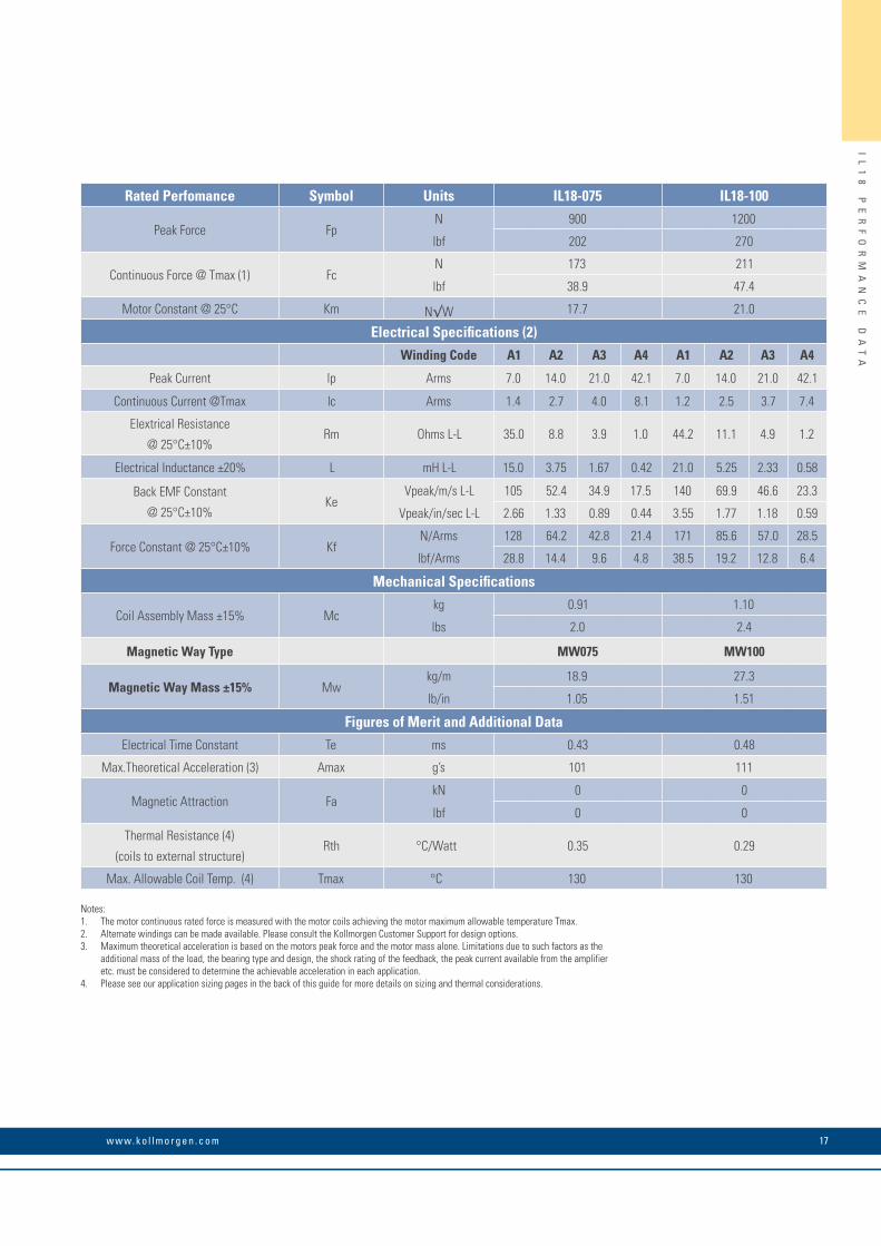
Rated Perfomance Symbol Units IL18-075 IL18-100
Peak Force FpN 900 1200
lbf 202 270
Continuous Force @ Tmax (1) FcN 173 211
lbf 38.9 47.4
Motor Constant @ 25°C Km N√W 17.7 21.0
Electrical Specifications (2)Winding Code A1 A2 A3 A4 A1 A2 A3 A4
Peak Current lp Arms 7.0 14.0 21.0 42.1 7.0 14.0 21.0 42.1
Continuous Current @Tmax lc Arms 1.4 2.7 4.0 8.1 1.2 2.5 3.7 7.4
Elextrical Resistance
@ 25°C±10%Rm Ohms L-L 35.0 8.8 3.9 1.0 44.2 11.1 4.9 1.2
Electrical Inductance ±20% L mH L-L 15.0 3.75 1.67 0.42 21.0 5.25 2.33 0.58
Back EMF Constant
@ 25°C±10%Ke
Vpeak/m/s L-L 105 52.4 34.9 17.5 140 69.9 46.6 23.3
Vpeak/in/sec L-L 2.66 1.33 0.89 0.44 3.55 1.77 1.18 0.59
Force Constant @ 25°C±10% KfN/Arms 128 64.2 42.8 21.4 171 85.6 57.0 28.5
lbf/Arms 28.8 14.4 9.6 4.8 38.5 19.2 12.8 6.4
Mechanical Specifications
Coil Assembly Mass ±15% Mckg 0.91 1.10
lbs 2.0 2.4
Magnetic Way Type MW075 MW100
Magnetic Way Mass ±15% Mwkg/m 18.9 27.3
lb/in 1.05 1.51
Figures of Merit and Additional DataElectrical Time Constant Te ms 0.43 0.48
Max.Theoretical Acceleration (3) Amax g’s 101 111
Magnetic Attraction FakN 0 0
lbf 0 0
Thermal Resistance (4)
(coils to external structure)Rth °C/Watt 0.35 0.29
Max. Allowable Coil Temp. (4) Tmax °C 130 130
Notes:1. The motor continuous rated force is measured with the motor coils achieving the motor maximum allowable temperature Tmax.2. Alternate windings can be made available. Please consult the Kollmorgen Customer Support for design options.3. Maximum theoretical acceleration is based on the motors peak force and the motor mass alone. Limitations due to such factors as the additional mass of the load, the bearing type and design, the shock rating of the feedback, the peak current available from the amplifier etc. must be considered to determine the achievable acceleration in each application.4. Please see our application sizing pages in the back of this guide for more details on sizing and thermal considerations.

IL
18
O
UT
LI
NE
D
RA
WI
NG
S
IL18 Outline Drawings
31.4(1.236)
40.0(1.575)6 PL.
302.8 (11.922) MAX.
51.4(2.023)
40.0(1.575)5 PL.
4.5(.176)
10.8(.427)
"B"
4.4(.173)
24.4(.961)
COIL ASSEMBLY
MAGNET WAYREF.
17.0(.669)
4.0(.157)
3.9(.152)
16.7(.657)
M5 X 0.8 X 5 DP.14 PL., 7 PER SIDE
M5 X 0.8 X 5 DP. 12 PL.
"A"
10.0(.394)
"T"
BOTHSIDES
BOTHSIDES
1.2 .05(.048 .002)
CLEARANCE-SET UP DIM.
FOR MOTOR CABLEAND HALL EFFECT MTG.SEE DRAWING BELOW
COIL TO MAGNET AIRGAP0.74 REF TYP. FOR 030, -050
1.12 REF TYP. FOR -075 AND -100
STANDARD LENGTH,SEE TABLE
THERMAL PROTECTION CONNECTOR: 2 PIN - M ALE C ONNEC TO R FREE HANGING RECEPT ACLE MOLEX P/N 43025-0200 2 FEM ALE TERMINALS MOLEX P/N 43030-0010
MOTOR CONNECTOR: POSITR ONIC P/N: CBD3W3M0000Z 3 PIN M ALE , SHELL SIZE 2MALE CO NTACTS: POSITR ONIC P/N: MS40--D 3 REMOV ABLE M ALE CONT ACTS, SIZE 8
12
321
PIN 1
PIN 1
PIN 1
PIN 9
PIN 5
21.0(.827)MAX.
#4-40 JA CKNUT (2)(REMOV ABLE FOR BULKHEAD MOUNTING)
HALL EFFEC T ASSEMBL Y
CO IL ASSEMBLY REF
HALL EFFEC T CONNECTOR OPTION: POSITR ONIC P/N: MD9M2000Z 9 PIN, M ALEMATING CONNECTOR REFERENCE: POSITR ONIC P/N: MD9F2000X
SEE WIRE TABLE, PAGE 70
MATING CONNECTOR REFERENCE: POSITR ONIC P/N: CBD3W3F0000X 3 FEM ALE SOCKE TS, SO LDER TYPE, SIZE 8, POSITR ONIC P/N: FS40--D
SEE WIRE TABLE, PAGE 70
MATING CONNECTOR REFERENCE: MOLEX " MICR O -F IT 3.0" PL UG: 43020-0201 MALE TERMINALS: 43031-0010
SEE WIRE TABLE, PAGE 70
4.0 .3(.157 .012)
STANDARD LENGTH,SEE TABLE
CO IL ASSEMBLY REF
6.8 .3(.268 .012)
7.7 .3(.303 .012)
MOTOR CABLE
OPTIONAL HALL EFFEC T AS SHOWN, MOUNTING HOLESM3 X 6.3 (.25) MIN. DP . 2 PL.
THERMAL
MOTOR
HALLEFFEC T
HALL EFFEC T MASSW/P* C ONNEC TO R: .05KG (.11 LB) MAXW/C* C ABLE: .03K G (.06 LB) M AX
12.2 .3(.480 .012)
+_+_
+_+_
+_+_
+_+_
Notes:1. Dimensions in mm (inches)2. Tolerances unless otherwise specified: no decimal place ±0.8 (0.3) X decimal place ±0.1 (.004) XX decimal place ±0.05 (0.002)
Motor CoilCoil Width Typ. Assy. Width Typ. Assy. Width
"A" +.7 (0.027) -.3 (0.012) "B" ±.6 (.024) "T" ±.4 (.016)
IL18-030 57.30 (2.256) 78.50 (3.091) 25.40 (1.000) IL18-030 L 57.30 (2.256) 67.30 (2.650) 25.40 (1.000) IL18-050 77.30 (3.043) 98.50 (3.878) 25.40 (1.000)
IL18-050 L 77.30 (3.043) 87.30 (3.437) 25.40 (1.000) IL18-075 102.30 (4.028) 123.50 (4.862) 30.00 (1.181) IL18-100 127.30 (5.012) 148.50 (5.846) 34.00 (1.339)
Termination and Hall Effect Options
Connector OptionConnector Length
P1 400 (16)P2 200 (8)P3 100 (4)P4 1200 (48)
Flying Lead OptionLeads Length
C1 400 (16)C2 200 (8)C3 100 (4)C4 1200 (48)
Note:Cables exiting motor and hall effects are not dynamic flex cables. For high life flex extension cables, see page 72
Ironless Non-Cooled Motors Series
K O L L M O R G E N 18

IL
18
O
UT
LI
NE
D
RA
WI
NG
S
Notes
19w w w. k o l l m o r g e n . c o m

K O L L M O R G E N 20
IL
24
P
ER
FO
RM
AN
CE
D
AT
A
IL24 Performance Data
Rated Perfomance Symbol Units IL24-030 IL24-050 IL24-075 IL24-100
Peak Force FpN 480 800 1200 1600
lbf 108 180 270 360
Continuous Force @ Tmax (1) FcN 109 155 211 262
lbf 24.5 34.8 47.4 58.9
Motor Constant @ 25°C Km N√W 11.2 15.9 20.6 24.4
Electrical Specifications (2)Winding Code A1 A2 A3 A1 A2 A3 A1 A2 A3 A4 A1 A2 A3 A4
Peak Current lp Arms 7.1 14.2 28.5 7.0 14.0 28.1 7.0 14.0 28.0 56.1 7.0 14.0 28.1 56.1
Continuous Current @Tmax lc Arms 1.6 3.2 6.4 1.4 2.7 5.4 1.2 2.5 4.9 9.9 1.2 2.3 4.6 9.2
Elextrical Resistance
@ 25°C±10%Rm Ohms L-L 24.3 6.1 1.5 34.3 8.6 2.1 46.6 11.7 2.9 0.73 58.9 14.7 3.7 0.92
Electrical Inductance ±20% L mH L-L 5.1 1.28 0.32 12.0 3.00 0.75 20.0 5.0 1.25 0.31 28.0 7.00 1.75 0.44
Back EMF Constant
@ 25°C±10%Ke
Vpeak/m/s L-L 55.0 27.5 13.8 93.1 46.5 23.3 140. 69.9 34.9 17.5 186 93.1 46.6 23.3
Vpeak/in/sec L-L 1.40 0.70 0.35 2.36 1.18 0.59 3.55 1.77 0.89 0.44 4.73 2.37 1.18 0.59
Force Constant
@ 25°C±10%Kf
N/Arms 67.4 33.7 16.9 114 57.0 28.5 171 85.6 42.8 21.4 228 114 57.0 28.5
lbf/Arms 15.2 7.6 3.8 25.6 12.8 6.4 38.5 19.2 9.6 4.8 51.3 25.6 12.8 6.4
Mechanical Specifications
Coil Assembly Mass ±15% Mckg 0.72 0.92 1.17 1.42
lbs 1.6 2.0 2.6 3.1
Magnetic Way TypeMW MW MW075 MW100
030 030L 050 050L
Magnetic Way Mass ±15% Mwkg/m 9.4 7.3 12.2 10.2 18.9 27.3
lb/in 0.51 0.40 0.68 0.56 1.05 1.51
Figures of Merit and Additional DataElectrical Time Constant Te ms 0.21 0.35 0.43 0.48
Max.Theoretical Acceleration(3) Amax g’s 68.0 88.7 105 115
Magnetic Attraction FakN 0 0 0 0
lbf 0 0 0 0
Thermal Resistance (4)
(coils to external structure)Rth °C/Watt 0.40 0.32 0.26 0.22
Max. Allowable Coil Temp. (4) Tmax °C 130 130 130 130
Notes:1. The motor continuous rated force is measured with the motor coils achieving the motor maximum allowable temperature Tmax.2. Alternate windings can be made available. Please consult the Kollmorgen Customer Support for design options.3. Maximum theoretical acceleration is based on the motors peak force and the motor mass alone. Limitations due to such factors as the additional mass of the load, the bearing type and design, the shock rating of the feedback, the peak current available from the amplifier etc. must be considered to determine the achievable acceleration in each application.4. Please see our application sizing pages in the back of this guide for more details on sizing and thermal considerations.
Ironless Non-Cooled Motors Series

21w w w. k o l l m o r g e n . c o m
IL
24
O
UT
LI
NE
D
RA
WI
NG
S
IL24 Outline Drawings
39.4(1.551)BOTHSIDES
40.0(1.575)8 PL.BOTHSIDES
398.8 (15.701) MAX.
19.4(.764)
40.0(1.575)9 PL.
4.0(.157)
3.8(.152)4.5
(.176)
M5 X 0.8 X 5 DP.18 PL., 9 PER SIDE
M5 X 0.8 X 5 DP.20 PL., 10 PER SIDE
"A"
10.8(.427)
"B"
4.4(.173)
24.4(.961)
COIL ASSEMBLY
MAGNET WAY REF.
17.0(.669)
16.7(.657)
10.0(.394)
"T"
1.2 .05(.048 .002)
CLEARANCE-SET UP DIM.
FOR MOTOR CABLEAND HALL EFFECT MTG.
SEE PAGE 19
COIL TO MAGNET AIRGAP0.74 REF TYP. FOR 030, -050
1.12 REF TYP. FOR -075 AND -100
Notes:1. Dimensions in mm (inches)2. Tolerances unless otherwise specified: no decimal place ±0.8 (0.3) X decimal place ±0.1 (.004) XX decimal place ±0.05 (0.002)
Motor CoilCoil Width Typ. Assy. Width Typ. Assy. Width
"A" +.7 (0.027) -.3 (0.012) "B" ±.6 (.024) "T" ±.4 (.016)
IL24-030 57.30 (2.256) 78.50 (3.091) 25.40 (1.000) IL24-030 L 57.30 (2.256) 67.30 (2.650) 25.40 (1.000) IL24-050 77.30 (3.043) 98.50 (3.878) 25.40 (1.000)
IL24-050 L 77.30 (3.043) 87.30 (3.437) 25.40 (1.000) IL24-075 102.30 (4.028) 123.50 (4.862) 30.00 (1.181) IL24-100 127.30 (5.012) 148.50 (5.846) 34.00 (1.339)
Ironless Non-Cooled Motors Series
STANDARD LENGTH,SEE TABLE
THERMAL PROTECTION CONNECTOR: 2 PIN - M ALE C ONNEC TO R FREE HANGING RECEPT ACLE MOLEX P/N 43025-0200 2 FEM ALE TERMINALS MOLEX P/N 43030-0010
MOTOR CONNECTOR: POSITR ONIC P/N: CBD3W3M0000Z 3 PIN M ALE , SHELL SIZE 2MALE CO NTACTS: POSITR ONIC P/N: MS40--D 3 REMOV ABLE M ALE CONT ACTS, SIZE 8
12
321
PIN 1
PIN 1
PIN 1
PIN 9
PIN 5
21.0(.827)MAX.
#4-40 JA CKNUT (2)(REMOV ABLE FOR BULKHEAD MOUNTING)
HALL EFFEC T ASSEMBL Y
CO IL ASSEMBLY REF
HALL EFFEC T CONNECTOR OPTION: POSITR ONIC P/N: MD9M2000Z 9 PIN, M ALEMATING CONNECTOR REFERENCE: POSITR ONIC P/N: MD9F2000X
SEE WIRE TABLE, PAGE 70
MATING CONNECTOR REFERENCE: POSITR ONIC P/N: CBD3W3F0000X 3 FEM ALE SOCKE TS, SO LDER TYPE, SIZE 8, POSITR ONIC P/N: FS40--D
SEE WIRE TABLE, PAGE 70
MATING CONNECTOR REFERENCE: MOLEX " MICR O -F IT 3.0" PL UG: 43020-0201 MALE TERMINALS: 43031-0010
SEE WIRE TABLE, PAGE 70
4.0 .3(.157 .012)
STANDARD LENGTH,SEE TABLE
CO IL ASSEMBLY REF
6.8 .3(.268 .012)
7.7 .3(.303 .012)
MOTOR CABLE
OPTIONAL HALL EFFEC T AS SHOWN, MOUNTING HOLESM3 X 6.3 (.25) MIN. DP . 2 PL.
THERMAL
MOTOR
HALLEFFEC T
HALL EFFEC T MASSW/P* C ONNEC TO R: .05KG (.11 LB) MAXW/C* C ABLE: .03K G (.06 LB) M AX
12.2 .3(.480 .012)
+_+_
+_+_
+_+_
+_+_
Termination and Hall Effect Options
Connector OptionConnector Length
P1 400 (16)P2 200 (8)P3 100 (4)P4 1200 (48)
Flying Lead OptionLeads Length
C1 400 (16)C2 200 (8)C3 100 (4)C4 1200 (48)
Note:Cables exiting motor and hall effects are not dynamic flex cables. For high life flex extension cables, see page 72

K O L L M O R G E N 22
IR
ON
LE
SS
M
AG
NE
T
WA
YS
Ironless Magnet WaysMWxxx-0064
M
9.00 ±.13(.354 ±.005)
A A
SEE TABLE
32.0(1.260)
MAGNETIC AIR GAP
M5 X 0.8 X 8 DP. 2 PL.
"W"
MAGNETLENGTH
32.0(1.260)
REF.
63.3 ±.4(2.492 ±.016)
Ø5.160-5.185 (.203-.204) X 6 (.236) DP.2 PL. MARKED "A", BOTH SIDESCUSTOMER TOOLING HOLES,SEE PAGE 30
22.94(.903)MAX.
22.94(.903)MAX.
18.00 ±.05(.709 ±.002)
18.00 ±.05(.709 ±.002)
"Z"
"H"
7.00(.276)
Ø5.160-5.185 (.203-.204) X 10 (.394) DP. 2 PL. MARKED "B",CUSTOMER TOOLING HOLES, SEE PAGE 30
B BCL
Magnet assemblies are modular and can be installed in multiples of same or
alternate lengths (see page 30). Standard assembly lengths are shown below.
Notes:1. Dimensions in mm (inches)2. Tolerances unless otherwise specified: no decimal place ±0.8 (0.3) X decimal place ±0.1 (.004) XX decimal place ±0.05 (0.002)
M
A A
32.0(1.260)3 PL. M5 X 0.8 X 8 DP. 4 PL.
M
64.0(2.520)
"W" Ø5.160-5.185 (.203-.204) X 6 (.236) DP.2 PL. MARKED "A", BOTH SIDESCUSTOMER TOOLING HOLES,SEE PAGE 30
127.3 ±.4(5.012 ±.016)
9.00 ±.13(.354 ± .005)
22.94(.903)MAX.
82.00 ±.05(3.228 ±.002)
82.00 ±.05(3.228 ±.002)
32.0(1.260)
REF.
MAGNETIC AIR GAP
MAGNETLENGTH
"Z"
"H"
22.94(.903)MAX.
7.00(.276)
B B
Ø5.160-5.185 (.203-.204)X 10 (.394) DP. 2 PL.MARKED "B", CUSTOMERTOOLING HOLES, SEE PAGE 30
SEE TABLE
CL
MWxxx-0128
Magnet Way Magnet Size "H" "W" "Z"Ref. ±.8 (.003) ±.4 (.016) ±.4 (.016)
MW030-0128 30mm 7.11 (.280) 60.20 (2.370) 25.40 (1.000)MW030L-0128 30mm 5.69 (.224) 49.00 (1.929) 25.40 (1.000)MW050-0128 50mm 7.11 (.280) 80.20 (3.158) 25.40 (1.000)MW050L-0128 50mm 5.69 (.224) 69.00 (2.716) 25.40 (1.000)MW075-0128 75mm 8.23 (.324) 105.20 (4.142) 30.00 (1.181)MW100-0128 100mm 8.23 (.324) 130.20 (5.126) 34.00 (1.339)
Magnet WayHardware (Hex, Socket Head Cap)
Hole Dia. C'bore Dia. Cbore Depth Metric Inch Bottom Mount±.13 (.005) ±.13 (.005) ±.13 (.005) Thread Option
MW030-0128 5.70 (.224) 9.35 (.368) 5.79 (.228) M5 #10 M5 X 0.8 X 8.0 DP.MW030L-0128 4.70 (.185) 7.80 (.307) 5.79 (.228) M4 #8 M4 X 0.7 X 6.0 DP.MW050-0128 5.70 (.224) 9.35 (.368) 5.79 (.228) M5 #10 M5 X 0.8 X 8.0 DP.MW050L-0128 4.70 (.185) 7.80 (.307) 5.79 (.228) M4 #8 M4 X 0.7 X 6.0 DP.MW075-0128 5.70 (.224) 9.35 (.368) 7.95 (.313) M5 #10 M5 X 0.8 X 8.0 DP.MW100-0128 5.70 (.224) 9.35 (.368) 9.96 (.392) M5 #10 M5 X 0.8 X 8.0 DP.
Magnet WayHardware (Hex, Socket Head Cap)
Hole Dia. C'bore Dia. Cbore Depth Metric Inch Bottom Mount±.13 (.005) ±.13 (.005) ±.13 (.005) Thread Option
MW030-0064 5.70 (.224) 9.35 (.368) 5.79 (.228) M5 #10 M5 X 0.8 X 8.0 DP.MW030L-0064 4.70 (.185) 7.80 (.307) 5.79 (.228) M4 #8 M4 X 0.7 X 6.0 DP.MW050-0064 5.70 (.224) 9.35 (.368) 5.79 (.228) M5 #10 M5 X 0.8 X 8.0 DP.MW050L-0064 4.70 (.185) 7.80 (.307) 5.79 (.228) M4 #8 M4 X 0.7 X 6.0 DP.MW075-0064 5.70 (.224) 9.35 (.368) 7.95 (.313) M5 #10 M5 X 0.8 X 8.0 DP.MW100-0064 5.70 (.224) 9.35 (.368) 9.96 (.392) M5 #10 M5 X 0.8 X 8.0 DP.
Magnet Way Magnet Size "H" "W" "Z"Ref. ±.8 (.003) ±.4 (.016) ±.4 (.016)
MW030-0064 30mm 7.11 (.280) 60.20 (2.370) 25.40 (1.000)MW030L-0064 30mm 5.69 (.224) 49.00 (1.929) 25.40 (1.000)MW050-0064 50mm 7.11 (.280) 80.20 (3.158) 25.40 (1.000)MW050L-0064 50mm 5.69 (.224) 69.00 (2.716) 25.40 (1.000)MW075-0064 75mm 8.23 (.324) 105.20 (4.142) 30.00 (1.181)MW100-0064 100mm 8.23 (.324) 130.20 (5.126) 34.00 (1.339)

23w w w. k o l l m o r g e n . c o m
IR
ON
LE
SS
M
AG
NE
T
WA
YS
MWxxx-0256Magnet assemblies are modular and can be installed in multiples of same or
alternate lengths (see page 30). Standard assembly lengths are shown below.
Notes:1. Dimensions in mm (inches)2. Tolerances unless otherwise specified: no decimal place ±0.8 (0.3) X decimal place ±0.1 (.004) XX decimal place ±0.05 (0.002)M
64.0(2.520)3 PL.
M
A A
"W"
M5 X 0.8 X 8 DP. 8 PL.
M
9.00 ±.13(.354 ±.005)
210.0 ±.05(8.268 ±.002)
210.0 ±.05(8.268 ±.002)
22.94(.903)MAX.
Ø5.160-5.185 (.203-.204) X 6 (.236) DP.2 PL. MARKED "A", BOTH SIDESCUSTOMER TOOLING HOLES, SEE PAGE 30
255.3 ±.4(10.051 ±.016) MAGNETIC AIR GAP
MAGNETLENGTH
"Z"
"H"
32.0(1.260)7 PL.
32.0(1.260)
REF.
22.94(.903)MAX.
7.00(.276)
B B
Ø5.160-5.185 (.203-.204)X 10 (.394) DP. 2 PL.MARKED "B", CUSTOMERTOOLING HOLES, SEE PAGE 30
SEE TABLE
CL
M
A A
32.0(1.260)3 PL. M5 X 0.8 X 8 DP. 4 PL.
M
64.0(2.520)
"W" Ø5.160-5.185 (.203-.204) X 6 (.236) DP.2 PL. MARKED "A", BOTH SIDESCUSTOMER TOOLING HOLES,SEE PAGE 30
127.3 ±.4(5.012 ±.016)
9.00 ±.13(.354 ± .005)
22.94(.903)MAX.
82.00 ±.05(3.228 ±.002)
82.00 ±.05(3.228 ±.002)
32.0(1.260)
REF.
MAGNETIC AIR GAP
MAGNETLENGTH
"Z"
"H"
22.94(.903)MAX.
7.00(.276)
B B
Ø5.160-5.185 (.203-.204)X 10 (.394) DP. 2 PL.MARKED "B", CUSTOMERTOOLING HOLES, SEE PAGE 30
SEE TABLE
CL
MWxxx-0512
Magnet Way Magnet Size "H" "W" "Z"Ref. ±.8 (.003) ±.4 (.016) ±.4 (.016)
MW030-0512 30mm 7.11 (.280) 60.20 (2.370) 25.40 (1.000)MW030L-0512 30mm 5.69 (.224) 49.00 (1.929) 25.40 (1.000)MW050-0512 50mm 7.11 (.280) 80.20 (3.158) 25.40 (1.000)MW050L-0512 50mm 5.69 (.224) 69.00 (2.716) 25.40 (1.000)MW075-0512 75mm 8.23 (.324) 105.20 (4.142) 30.00 (1.181)MW100-0512 100mm 8.23 (.324) 130.20 (5.126) 34.00 (1.339)
Magnet WayHardware (Hex, Socket Head Cap)
Hole Dia. C'bore Dia. Cbore Depth Metric Inch Bottom Mount±.13 (.005) ±.13 (.005) ±.13 (.005) Thread Option
MW030-0512 5.70 (.224) 9.35 (.368) 5.79 (.228) M5 #10 M5 X 0.8 X 8.0 DP.MW030L-0512 4.70 (.185) 7.80 (.307) 5.79 (.228) M4 #8 M4 X 0.7 X 6.0 DP.MW050-0512 5.70 (.224) 9.35 (.368) 5.79 (.228) M5 #10 M5 X 0.8 X 8.0 DP.MW050L-0512 4.70 (.185) 7.80 (.307) 5.79 (.228) M4 #8 M4 X 0.7 X 6.0 DP.MW075-0512 5.70 (.224) 9.35 (.368) 7.95 (.313) M5 #10 M5 X 0.8 X 8.0 DP.MW100-0512 5.70 (.224) 9.35 (.368) 9.96 (.392) M5 #10 M5 X 0.8 X 8.0 DP.
Magnet Way Magnet Size "H" "W" "Z"Ref. ±.8 (.003) ±.4 (.016) ±.4 (.016)
MW030-0256 30mm 7.11 (.280) 60.20 (2.370) 25.40 (1.000)MW030L-0256 30mm 5.69 (.224) 49.00 (1.929) 25.40 (1.000)MW050-0256 50mm 7.11 (.280) 80.20 (3.158) 25.40 (1.000)MW050L-0256 50mm 5.69 (.224) 69.00 (2.716) 25.40 (1.000)MW075-0256 75mm 8.23 (.324) 105.20 (4.142) 30.00 (1.181)MW100-0256 100mm 8.23 (.324) 130.20 (5.126) 34.00 (1.339)
Magnet WayHardware (Hex, Socket Head Cap)
Hole Dia. C'bore Dia. Cbore Depth Metric Inch Bottom Mount±.13 (.005) ±.13 (.005) ±.13 (.005) Thread Option
MW030-0512 5.70 (.224) 9.35 (.368) 5.79 (.228) M5 #10 M5 X 0.8 X 8.0 DP.MW030L-0512 4.70 (.185) 7.80 (.307) 5.79 (.228) M4 #8 M4 X 0.7 X 6.0 DP.MW050-0512 5.70 (.224) 9.35 (.368) 5.79 (.228) M5 #10 M5 X 0.8 X 8.0 DP.MW050L-0512 4.70 (.185) 7.80 (.307) 5.79 (.228) M4 #8 M4 X 0.7 X 6.0 DP.MW075-0512 5.70 (.224) 9.35 (.368) 7.95 (.313) M5 #10 M5 X 0.8 X 8.0 DP.MW100-0512 5.70 (.224) 9.35 (.368) 9.96 (.392) M5 #10 M5 X 0.8 X 8.0 DP.
Magnet assemblies are modular and can be installed in multiples of same or
alternate lengths (see page 30). Standard assembly lengths are shown below.

K O L L M O R G E N 24
IR
ON
LE
SS
M
AG
NE
T
WA
YS
Ironless Magnet Ways
Bottom Mounting Installation
Magnet Way widths correspond to the mating coil assembly width.
Magnet Way assemblies are modular and come in standard lengths: 64, 128, 256, 512 mm.
Dimensions in mm (in)
Side mounting installation
64MM MAGNETWAY, REF.
46.00(1.811)
REF.
5.33 (.210)4.83 (.190)
4.9(.193)
M4 HARDWARE
7.11(.280)
M5 HARDWARE
ADJACENTMAGNET WAY
REF.
CUSTOMER BANKING ORMOUNTING SURFACE, REF.
Ø5 M6 (.197) DOWEL PIN2 PER MAGNET WAYRECOMMENDED
PIN, REF.
MOUNTING HARDWARE(SEE MAGNET ASSEMBLYDRAWINGS FOR HARDWARE)
COIL ASSEMBLY, REF.
7.01(.276)REF.
RESULTANT GAP BETWEEN MAGNET ASSEMBLIES FROM PROPER PIN LOCATION. DO NOT BUTT MAGNET ASSEMBLIES.
Dimensions in mm (in)
46.00(1.811)
REF.
ADJACENT MAGNET WAYLENGHT OPTIONAL, REF.
64 MM MAGNETWAY, REF.
MOUNTINGSCREW, REF.
COIL ASSEMBLY, REF.
PIN, REF. Ø5 M62 REQ'D. FOR SIZE 64(PINS OPTIONAL ON OTHERSIZE MAGNET WAYS)
MOUNTING SCREW(SEE MAGNET ASSEMBLYDRAWINGS FOR HARDWARE)
CUSTOMER BANKING ORMOUNTING SURFACE, REF.
COIL ASSEMBLY, REF.COIL ASSEMBLY, REF.
5.35 (.211)4.85 (.191)
RESULTANT GAP BETWEEN MAGNET ASSEMBLIES FROM PROPER PIN LOCATION. DO NOT BUTT MAGNET ASSEMBLIES.

25w w w. k o l l m o r g e n . c o m
Notes
IR
ON
LE
SS
M
AG
NE
T
WA
YS

K O L L M O R G E N 26
IC
D0
5
PE
RF
OR
MA
NC
E
DA
TA
ICD05 Performance Data
Rated Perfomance Symbol Units ICD05-030 ICD05-050 ICD05-075 ICD05-100
Peak Force FpN 165 295 441 588
lbf 37.1 66.3 99.1 132
Continuous Force @ Tmax (1) FcN 57.0 87.0 125 157
lbf 12.8 19.6 28.1 35.3
Motor Constant @ 130°C KmN/√W 10.3 14.5 18.6 22.0
lbf/√W 2.3 3.3 4.2 4.9
Motor Constant @ 25°C Km25N/√W 12.3 17.2 22.0 26.0
lbf/√W 2.8 3.9 4.9 5.9
Electrical Specifications (2)Winding Code A1 A5 A1 A5 A1 A5 A1 A5
Peak Current lp Arms 7.9 13.7 8.5 14.7 8.5 14.7 8.5 14.7
Continuous Current @Tmax lc Arms 2.1 3.7 2.0 3.4 1.9 3.3 1.8 3.1
Elextrical Resistance @ 25°C±10% Rm Ohms L-L 3.2 1.1 4.5 1.5 6.1 2.0 7.7 2.6
ElectricalInductance ±20% L mh L-L 9.1 3.0 14.4 4.8 21.0 7.0 27.6 9.2
Back EMFConstantKe
Vpeak/m/s L-L 21.8 12.6 36.3 21.0 54.3 31.4 72.4 41.8
@25°C±10% Vpeak/in/sec L-L 0.55 0.32 0.92 0.53 1.38 0.80 1.84 1.06
Force Constant @ 25°C±10% KfN/Arms 26.7 15.4 44.5 25.7 66.5 38.4 88.7 51.2
lbf/Arms 6.0 3.5 10.0 5.8 15.0 8.6 19.9 11.5
Mechanical Specifications
Coil Assembly Mass ±15% Mckg 0.62 0.95 1.36 1.71
lbs 1.4 2.1 3.0 3.8
Magnetic Way Type MCD030 MCD050 MCD075 MCD100
Magnetic Way Mass ±15% Mwkg/m 2.70 3.93 5.48 7.04
lbs/in 0.15 0.22 0.31 0.39
Figures of Merit and Additional DataElectrical Time Constant Te ms 2.9 3.2 3.4 3.6
Max.Theoretical Acceleration (3) Amax g’s 28.0 30.2 31.9 32.8
Magnetic Attraction FakN 0.53 0.89 1.33 1.78
lbf 119 200 299 400
Thermal Resistance (4)
(coils to external structure)Rth °C/Watt 3.50 2.90 2.30 2.06
Max. Allowable Coil Temp. (4) Tmax °C 130 130 130 130
Notes:1. The motor continuous rated force is measured with the motor coils achieving the motor maximum allowable temperature Tmax.2. Alternate windings can be made available. Please consult the Kollmorgen Customer Support for design options.3. Maximum theoretical acceleration is based on the motors peak force and the motor mass alone. Limitations due to such factors as the additional mass of the load, the bearing type and design, the shock rating of the feedback, the peak current available from the amplifier etc. must be considered to determine the achievable acceleration in each application.4. Please see our application sizing pages in the back of this guide for more details on sizing and thermal considerations.
Ironcore Motors Series

27w w w. k o l l m o r g e n . c o m
IC
D0
5
OU
TL
IN
E
DR
AW
IN
GS
ICD05 Outline Drawings
STANDARD LENGTH,SEE TABLE
THERMAL PROTECTION CONNECTOR: 2 PIN - MALE CONNECTOR FREE HANGING RECEPTACLE MOLEX P/N 43025-0200 2 FEMALE TERMINALS MOLEX P/N 43030-0010
MOTOR CONNECTOR: POSITRONIC P/N: CBD3W3M0000Z 3 PIN, MALE SHELL, SIZE 2MALE CONTACTS: POSITRONIC P/N: MS40--D 3 REMOVABLE MALE CONTACTS, SIZE 8
12
PIN1
PIN1
PIN1
PIN 9
PIN 5
26.8(1.055)MAX.
#4-40 JACKNUT (2)(REMOVABLE FOR BULKHEAD MOUNTING)
HALL EFFECT ASSEMBLY
COIL ASSEMBLY REF
STANDARD LENGTH,SEE TABLE
COIL ASSEMBLYREF
31.7(1.25)
THERMAL
MOTOR
HALLEFFECT
MOTOR CABLE
HALL EFFECT MASSW/P* CONNECTOR: .07 KG (.15 LB) MAXW/C* CABLE: .03 KG (.07 LB) MAX
14.0(.551)
9.0(.355)
HALL EFFECT CONNECTOR OPTION: POSITRONIC P/N: MD9M2000Z 9 PIN, MALEMATING CONNECTOR REFERENCE: POSITRONIC P/N: MD9F2000X SEE WIRE TABLE, PAGE 70
MATING CONNECTOR REFERENCE: POSITRONIC P/N: CBD3W3F0000X 3 FEMALE SOCKETS, SOLDER TYPE, SIZE 8, POSITRONIC P/N: FS40--D
SEE WIRE TABLE, PAGE 70
MATING CONNECTOR REFERENCE: MOLEX "MICRO-FIT 3.0" PLUG: 43020-0201 MALE TERMINALS: 43031-0010
SEE WIRE TABLE, PAGE 70
99.0(3.898)
2.0(.079)
M2.5 PAN HEADSCREW, 2 PL.
FOR MOTOR CABLEAND HALL EFFECT MTG.SEE DRAWING BELOW
M2.5 X 3 mm DP"N" NUMBER OF HOLESPER MOUNTING BAR
HALL EFFECT (OPTIONAL)
MAGNET WAY REF
COIL ASSY
32.6 MIN. REQ'D.
MACH. ENVELOPE
(.492)TYP
12.5
(1.283)
(.913)
DIM 'X'
26.8 (1.055)MAX
14.0(.551)9.0
(.355)
23.2 REF
FOR MORE DETAIL.)
(PLEASE REFER TOINSTALLATION MANUAL
COIL AND MAGNET WAY:
0.6±0.1 mm w/COVER0.8±0.1mm w/o COVER
PASSES FREELY BETWEENSO THAT SPECIFIED SHIMAIRGAP SHOULD BE SET
6.0 (.24)TYP
15.7(.618)
24.0 (.945)TYP
30.2(1.19) TYP
42.8 (1.69) TYP10.3
(Ø13/32)TYP 4 PL
Notes:1. Dimensions in mm (inches)2. Tolerances unless otherwise specified: no decimal place ±0.8 (0.3) X decimal place ±0.1 (.004) XX decimal place ±0.05 (0.002)
Motor Coil Type
Coil Width # Holes"X" "N"
ICD05-030 55.0 (2.165) ± 1.0 (.04) 3 ICD05-050 75.0 (2.953) ± 1.0 (.04) 4 ICD05-075 100.0 (3.937) ± 1.0 (.04) 5 ICD05-100 125.0 (4.921) ± 1.0 (.04) 5
Connector OptionConnector Length
P1 400 (16)P2 200 (8)P3 100 (4)P4 1200 (48)
Flying Lead OptionLeads Length
C1 400 (16)C2 200 (8)C3 100 (4)C4 1200 (48)
Note:Cables exiting motor and hall effects are not dynamic flex cables. For high life flex extension cables, see page 72

K O L L M O R G E N 28
IC
D1
0
PE
RF
OR
MA
NC
E
DA
TA
ICD10 Performance Data
Rated Perfomance Symbol Units ICD10-030 ICD10-050 ICD10-075 ICD10-100
Peak Force FpN 330 550 824 1099
lbf 74.2 124 185 247
Continuous Force @ Tmax (1) FcN 104 171 246 315
lbf 23.4 38.4 55.3 70.8
Motor Constant @ 130°C KmN/√W 14.6 20.5 26.4 31.3
lbf/√W 3.3 4.6 5.9 7.0
Motor Constant @ 25°C Km25N/√W 17.3 24.3 31.3 37.1
lbf/√W 3.9 5.5 7.0 8.3
Electrical Specifications (2)Winding Code A1 A4 A5 A8 A1 A4 A5 A8 A1 A4 A5 A8 A1 A4 A5 A8
Peak Current lp Arms 7.9 15.8 13.7 27.4 7.9 15.8 13.7 27.4 7.9 15.8 13.7 27.4 7.9 15.8 13.7 27.4
Continuous Current @Tmax lc Arms 1.9 3.9 3.4 6.8 1.9 3.8 3.3 6.6 1.8 3.7 3.2 6.4 1.8 3.5 3.1 6.1
ElextricalResistanceRm Ohms L-L 6.4 1.6 2.1 0.5 9.0 2.2 3.0 0.7 12.2 3.0 4.1 1.0 15.4 3.9 5.1 1.3
@ 25°C±10%
Electrical Inductance ±20% L mh L-L 18.3 4.6 6.1 1.5 29.0 7.3 9.7 2.4 42.4 10.6 14.1 3.5 55.8 13.9 18.6 4.6
Back EMF ConstantKe
Vpeak/m/s L-L 43.7 21.8 25.2 12.6 72.8 36.4 42.0 21.0 109.2 54.6 63.1 31.5 145.7 72.8 84.1 42.0
@25°C±10% Vpeak/in/sec L-L 1.11 0.55 0.64 0.32 1.85 0.92 1.07 0.53 2.77 1.39 1.60 0.80 3.70 1.85 2.14 1.07
Force Constant @ 25°C±10% KfN/Arms 53.5 26.8 30.9 15.4 89.2 44.6 51.5 25.7 134 66.9 77.2 38.6 178 89.2 103 51.5
lbf/Arms 12.0 6.0 6.9 3.5 20.1 10.0 11.6 5.8 30.1 15.0 17.4 8.7 40.1 20.1 23.2 11.6
Mechanical Specifications
Coil Assembly Mass ±15% Mckg 1.1 1.9 2.7 3.4
lbs 2.5 4.1 5.9 7.5
Magnetic Way Type MCD030 MCD050 MCD075 MCD100
Magnetic Way Mass ±15% Mwkg/m 2.70 3.93 5.48 7.04
lbs/in 0.15 0.22 0.31 0.39
Figures of Merit and Additional DataElectrical Time Constant Te ms 2.9 3.2 3.5 3.6
Max.Theoretical Acceleration(3) Amax g’s 30.7 30.7 32.5 33.7
Magnetic Attraction FakN 1.06 1.78 2.66 3.56
lbf 2.38 400 598 800
Thermal Resistance (4)
(coils to external structure)Rth °C/Watt 2.05 1.52 1.21 1.04
Max. Allowable Coil Temp. (4) Tmax °C 130 130 130 130
Notes:1. The motor continuous rated force is measured with the motor coils achieving the motor maximum allowable temperature Tmax.2. Alternate windings can be made available. Please consult the Kollmorgen Customer Support for design options.3. Maximum theoretical acceleration is based on the motors peak force and the motor mass alone. Limitations due to such factors as the additional mass of the load, the bearing type and design, the shock rating of the feedback, the peak current available from the amplifier etc. must be considered to determine the achievable acceleration in each application.4. Please see our application sizing pages in the back of this guide for more details on sizing and thermal considerations.
Ironcore Motors Series

29w w w. k o l l m o r g e n . c o m
IC
D1
0
OU
RL
IN
E
DR
AW
IN
GS
ICD10 Outline Drawings
STANDARD LENGTH,SEE TABLE
THERMAL PROTECTION CONNECTOR: 2 PIN - MALE CONNECTOR FREE HANGING RECEPTACLE MOLEX P/N 43025-0200 2 FEMALE TERMINALS MOLEX P/N 43030-0010
MOTOR CONNECTOR: POSITRONIC P/N: CBD3W3M0000Z 3 PIN, MALE SHELL, SIZE 2MALE CONTACTS: POSITRONIC P/N: MS40--D 3 REMOVABLE MALE CONTACTS, SIZE 8
12
PIN1
PIN1
PIN1
PIN 9
PIN 5
26.8(1.055)MAX.
#4-40 JACKNUT (2)(REMOVABLE FOR BULKHEAD MOUNTING)
HALL EFFECT ASSEMBLY
COIL ASSEMBLY REF
STANDARD LENGTH,SEE TABLE
COIL ASSEMBLYREF
31.7(1.25)
THERMAL
MOTOR
HALLEFFECT
MOTOR CABLE
HALL EFFECT MASSW/P* CONNECTOR: .07 KG (.15 LB) MAXW/C* CABLE: .03 KG (.07 LB) MAX
14.0(.551)
9.0(.355)
HALL EFFECT CONNECTOR OPTION: POSITRONIC P/N: MD9M2000Z 9 PIN, MALEMATING CONNECTOR REFERENCE: POSITRONIC P/N: MD9F2000X SEE WIRE TABLE, PAGE 70
MATING CONNECTOR REFERENCE: POSITRONIC P/N: CBD3W3F0000X 3 FEMALE SOCKETS, SOLDER TYPE, SIZE 8, POSITRONIC P/N: FS40--D
SEE WIRE TABLE, PAGE 70
MATING CONNECTOR REFERENCE: MOLEX "MICRO-FIT 3.0" PLUG: 43020-0201 MALE TERMINALS: 43031-0010
SEE WIRE TABLE, PAGE 70
Notes:1. Dimensions in mm (inches)2. Tolerances unless otherwise specified: no decimal place ±0.8 (0.3) X decimal place ±0.1 (.004) XX decimal place ±0.05 (0.002)
Motor Coil Type
Coil Width # Holes"X" "N"
ICD10-030 55.0 (2.165) ± 1.0 (.04) 3 ICD10-050 75.0 (2.953) ± 1.0 (.04) 4 ICD10-075 100.0 (3.937) ± 1.0 (.04) 5 ICD10-100 125.0 (4.921) ± 1.0 (.04) 5
TYP
MIN. REQ'D.MACH. ENVELOPE
DIM 'X'
26.8 (1.055) MAX
19.7 (.777)24.0 (.945) TYP
TYP 4 PL
179.0(7.047)
COIL ASSY
M2.5 PAN HEADSCREW, 2 PL.
2.0(.079)
23.2(.913)
32.6(1.283)
HALL EFFECT (OPTIONAL)
M2.5 X 3 mm DP"N" NUMBER OF HOLESPER MOUNTING BAR
FOR MOTOR CABLEAND HALL EFFECT MTG.SEE DRAWING BELOW
MAGNET WAY REF
12.5(.492)
14.0(.551)
9.0(.355)
REF
34.0 (1.34) TYP
115.0(4.53) TYP
10.3 (.406)(Ø13/32)
6.0 (.24) TYP
AIRGAP SHOULD BE SETSO THAT SPECIFIED SHIMPASSES FREELY BETWEENCOIL AND MAGNET WAY:0.8±0.1mm w/o COVER0.6±0.1 mm w/COVER(PLEASE REFER TOINSTALLATION MANUALFOR MORE DETAIL.)
Termination and Hall Effect Options
Connector OptionConnector Length
P1 400 (16)P2 200 (8)P3 100 (4)P4 1200 (48)
Flying Lead OptionLeads Length
C1 400 (16)C2 200 (8)C3 100 (4)C4 1200 (48)
Note:Cables exiting motor and hall effects are not dynamic flex cables. For high life flex extension cables, see page 72
K O L L M O R G E N 30
IC
D
MA
GN
ET
W
AY
S
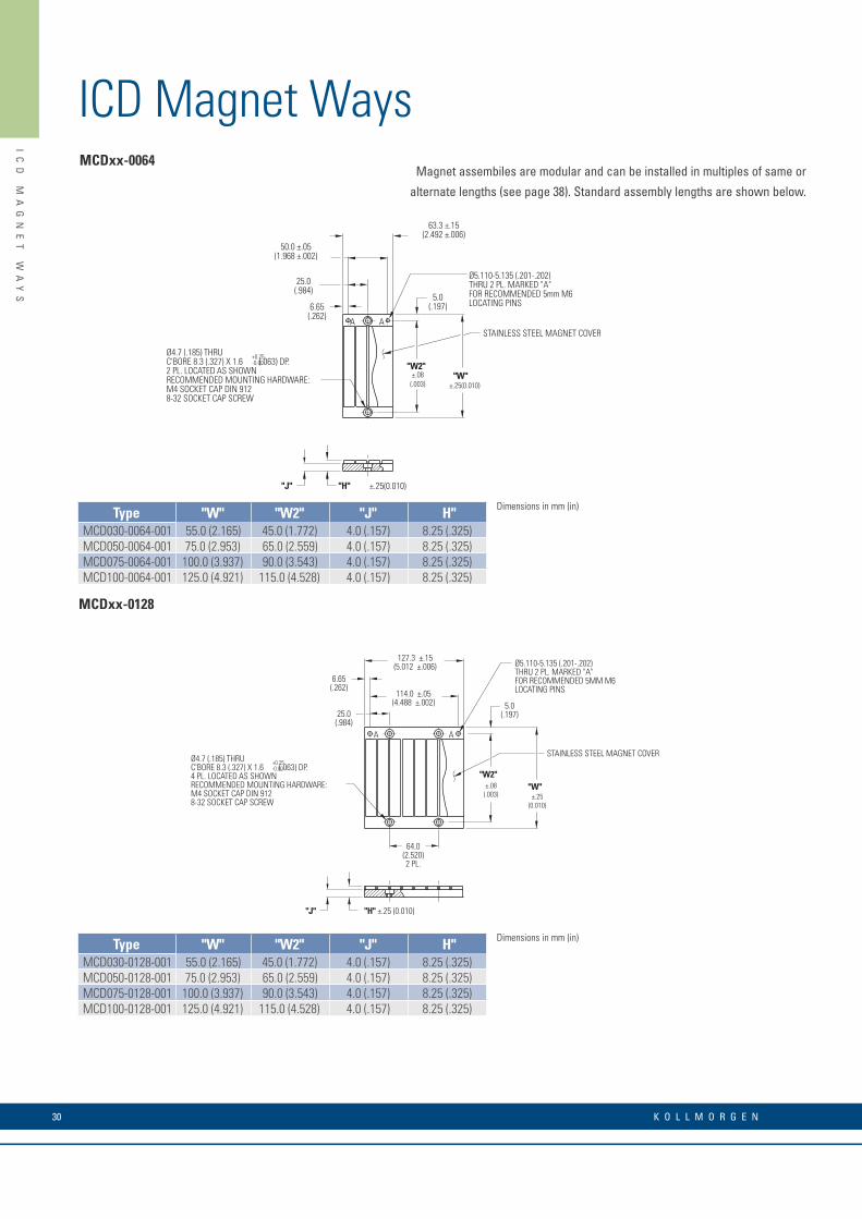
ICD Magnet WaysMCDxx-0064
A A
5.0(.197)
Ø4.7 (.185) THRUC'BORE 8.3 (.327) X 1.6 (.063) DP.2 PL. LOCATED AS SHOWNRECOMMENDED MOUNTING HARDWARE:M4 SOCKET CAP DIN 9128-32 SOCKET CAP SCREW
6.65(.262)
25.0(.984)
50.0 ±.05(1.968 ±.002)
63.3 ±.15(2.492 ±.006)
±.08(.003) ±.25(0.010)
±.25(0.010)
STAINLESS STEEL MAGNET COVER
"W""W2"
Ø5.110-5.135 (.201-.202)THRU 2 PL. MARKED "A"FOR RECOMMENDED 5mm M6LOCATING PINS
"J"
+0.25-0.00
"H"
MCDxx-0128
64.0(2.520)2 PL.
A
6.65(.262)
127.3 ±.15(5.012 ±.006)
A
114.0 ±.05(4.488 ±.002)
"W""W2"
5.0(.197)25.0
(.984)
±.25(0.010)
±.08(.003)
STAINLESS STEEL MAGNET COVER
"J" "H" ±.25 (0.010)
Ø5.110-5.135 (.201-.202)THRU 2 PL. MARKED "A"FOR RECOMMENDED 5MM M6LOCATING PINS
Ø4.7 (.185) THRUC'BORE 8.3 (.327) X 1.6 (.063) DP.4 PL. LOCATED AS SHOWNRECOMMENDED MOUNTING HARDWARE:M4 SOCKET CAP DIN 9128-32 SOCKET CAP SCREW
+0.25-0.00
Magnet assembiles are modular and can be installed in multiples of same or
alternate lengths (see page 38). Standard assembly lengths are shown below.
Type "W" "W2" "J" H"MCD030-0064-001 55.0 (2.165) 45.0 (1.772) 4.0 (.157) 8.25 (.325)MCD050-0064-001 75.0 (2.953) 65.0 (2.559) 4.0 (.157) 8.25 (.325)MCD075-0064-001 100.0 (3.937) 90.0 (3.543) 4.0 (.157) 8.25 (.325)MCD100-0064-001 125.0 (4.921) 115.0 (4.528) 4.0 (.157) 8.25 (.325)
Dimensions in mm (in)
Type "W" "W2" "J" H"MCD030-0128-001 55.0 (2.165) 45.0 (1.772) 4.0 (.157) 8.25 (.325)MCD050-0128-001 75.0 (2.953) 65.0 (2.559) 4.0 (.157) 8.25 (.325)MCD075-0128-001 100.0 (3.937) 90.0 (3.543) 4.0 (.157) 8.25 (.325)MCD100-0128-001 125.0 (4.921) 115.0 (4.528) 4.0 (.157) 8.25 (.325)
Dimensions in mm (in)

31w w w. k o l l m o r g e n . c o m
IC
D
MA
GN
ET
W
AY
S
64.0(2.520)6 PL.
A
255.3 ± .15(10.051 ± .006)
242.0 .05(9.528 .002)
A
"W2"
"W"
± .08(.003)
± .25(0.010)
5.0 (.197)6.65(.262)
25.0(.984)
STAINLESS STEEL MAGNET COVER
Ø5.110-5.135 (.201-.202)THRU 2 PL. MARKED "A"FOR RECOMMENDED 5mm M6LOCATING PINS
"J" "H" ±.25 (0.010)
Ø4.7 (.185) THRUC'BORE 8.3 (.327) X 1.6 (.063) DP.8 PL. LOCATED AS SHOWNRECOMMENDED MOUNTING HARDWARE:M4 SOCKET CAP DIN 9128-32 SOCKET CAP SCREW
+0.25-0.00
64.0(2.520)14 PL.
A
511.3 ±.15(20.130 ±.006)
498.0 ±.05(19.606 ±.002)
A
"W""W2"
±.25(0.010)
±.08(0.003)
5.0(.197)6.65
(.262)
25.0(.984)
"J"
"H" ±.25 (0.010)
Ø5.110-5.135 (.201-.202)THRU 2 PL. MARKED "A"FOR RECOMMENDED 5mm M6LOCATING PINS
Ø4.7 (.185) THRUC'BORE 8.3 (.327) X 1.6 (.063) DP.16 PL. LOCATED AS SHOWNRECOMMENDED MOUNTING HARDWARE:M4 SOCKET CAP DIN 9128-32 SOCKET CAP SCREW
+0.25-0.00
STAINLESS STEELMAGNET COVER
MCDxx-0256
MCDxx-0512
Type "W" "W2" "J" H"MCD030-0256-001 55.0 (2.165) 45.0 (1.772) 4.0 (.157) 8.25 (.325)MCD050-0256-001 75.0 (2.953) 65.0 (2.559) 4.0 (.157) 8.25 (.325)MCD075-0256-001 100.0 (3.937) 90.0 (3.543) 4.0 (.157) 8.25 (.325)MCD100-0256-001 125.0 (4.921) 115.0 (4.528) 4.0 (.157) 8.25 (.325)
Type "W" "W2" "J" H"MCD030-0512-001 55.0 (2.165) 45.0 (1.772) 4.0 (.157) 8.25 (.325)MCD050-0512-001 75.0 (2.953) 65.0 (2.559) 4.0 (.157) 8.25 (.325)MCD075-0512-001 100.0 (3.937) 90.0 (3.543) 4.0 (.157) 8.25 (.325)MCD100-0512-001 125.0 (4.921) 115.0 (4.528) 4.0 (.157) 8.25 (.325)
Dimensions in mm (in)
Dimensions in mm (in)

K O L L M O R G E N 32
IC
D
MA
GN
ET
W
AY
S
ICD Magnet Ways
M2.5 x 0.45 x 3 MM DPNUMBER OF HOLES "N"PER MOUNTING BAR
"S"
"C""L"
NUMBER OFMOUNTING "T" BARS"M"
Typical Mounting Bar Lengths & Mounting Holes Tabulation
Magnet Way widths correspond to the mating coil assembly width. Magnet Way assemblies are modular and come in standard
lengths: 64, 128, 256, 512 mm. Multiple magnet assemblies can be installed to obtain the desired length.
Shown below is the method to mount multiple assemblies.
AAAA A
1STMAGNET
ASSEMBLY
31.75(1.250)
6.75(.266)
64.0(2.520)
TYP BOLT MTG.
14.00(.551)
PIN LOC.RECOMMENDED
PIN Ø5 M6
2NDMAGNET
ASSEMBLY
3RDMAGNET
ASSEMBLY
PIN DATUM HOLES TO BE LOCATED ON SAME SIDE TO ENSURE CORRECT NORTH/SOUTH POLE ORIENTATION
Typical Installation of Multiple Ironcore Magnet Assemblies
Dimensions in mm (in)
Motor Coil Type
Number Spacing Mounting
of Holes Between Holes Bar Length
"N" "C" "L" "S"ICDXX-030 3 12.0 (.472) 30 (1.18) 3.0 (.118)ICDXX-050 4 12.0 (.472) 50 (1.97) 7.0 (2.76)ICDXX-075 5 16.0 (.630) 75 (2.95) 5.5 (.217)ICDXX-100 5 20.0 (.787) 100 (3.94) 10.0 (.394)
Dimensions in mm (in)
Motor Coil Type
Number
of Bars
"M"ICD05-XXX 4ICD10-XXX 7

33w w w. k o l l m o r g e n . c o m
IC
D
MA
GN
ET
W
AY
S
Notes
Dimensions in mm (in)
Dimensions in mm (in)

K O L L M O R G E N 34
IC
11
P
ER
FO
RM
AN
CE
D
AT
A
IC11 Performance Data
Rated Perfomance Symbol Units IC11-030 IC11-050 IC11-075 IC11-100 IC11-150 IC11-200
Peak Force FpN 320 533 800 1067 1600 2135
lbf 71.9 120 180 240 360 480
Continuous Force @ Tmax (1) FcN 144 263 413 574 861 1197
lbf 32.4 59.1 92.8 129 194 269
Motor Constant @ 25°C Km N/√W 22.5 32.0 41.4 49.1 62.0 73.0
Electrical Specifications (2)Winding Code A1 A5 A1 A5 A1 A5 A1 A5 A1 A5 A1 A5
Peak Current lp Arms 11.3 19.1 11.3 19.1 11.3 19.1 11.3 19.1 11.3 19.1 11.3 19.1
Continuous Current @Tmax lc Arms 4.0 6.9 4.4 7.6 4.6 8.0 4.8 8.2 4.8 8.3 5.0 8.6
ElextricalResistanceRm Ohms L-L 1.9 0.63 2.6 0.87 3.5 1.2 4.4 1.5 6.2 2.1 8.0 2.7
@ 25°C±10%
Electrical Inductance ±20% L mh L-L 16.7 5.6 26.7 8.9 39.4 13.1 52.0 17.3 77.3 25.8 103 34.2
Back EMF ConstantKe
Vpeak/m/s L-L 30.9 17.8 51.4 29.7 77.1 44.5 103 59.3 154 89.0 206 119
@25°C±10% Vpeak/in/sec L-L 0.78 0.45 1.30 0.75 1.96 1.13 2.61 1.51 3.92 2.26 5.22 3.02
Force Constant @ 25°C±10% KfN/Arms 37.8 21.8 62.9 36.3 94.4 54.5 126 72.7 189 109 252 145
lbf/Arms 8.5 4.9 14.1 8.2 21.2 12.3 28.3 16.3 42.4 24.5 56.6 32.7
Mechanical Specifications
Coil Assembly Mass ±15% Mckg 2.5 3.6 5.0 6.5 9.4 12.3
lbs 5.5 7.9 11.0 14.3 20.7 27.1
Magnetic Way Type MC030 MC050 MC075 MC100 MC150 MC200
Magnetic Way Mass ±15% Mwkg/m 5.4 7.5 10.1 12.7 20.7 26.8
lbs/in 0.30 0.42 0.56 0.71 1.16 1.50
Figures of Merit and Additional DataElectrical TimeConstant Te ms 8.8 10.3 11.3 11.8 12.5 12.8
Max.Theoretical Acceleration(3) Amax g’s 15.3 17.7 19.2 19.6 20.3 20.7
Magnetic Attraction FakN 1.4 2.4 3.7 4.9 7.3 9.9
lbf 324 546 821 1102 1639 2214
Thermal Resistance (4)
(coils to external structure)Rth °C/Watt 1.64 0.99 0.67 0.50 0.35 0.25
Max. Allowable Coil Temp. (4) Tmax °C 130 130 130 130 130 130
Notes:1. The motor continuous rated force is measured with the motor coils achieving the motor maximum allowable temperature Tmax.2. Alternate windings can be made available. Please consult the Kollmorgen Customer Support for design options.3. Maximum theoretical acceleration is based on the motors peak force and the motor mass alone. Limitations due to such factors as the additional mass of the load, the bearing type and design, the shock rating of the feedback, the peak current available from the amplifier etc. must be considered to determine the achievable acceleration in each application.4. Please see our application sizing pages in the back of this guide for more details on sizing and thermal considerations.
Ironcore Non-Cooled Motors Series

35w w w. k o l l m o r g e n . c o m
IC
11
O
UT
LI
NE
D
RA
WI
NG
S
IC11 Outline Drawings
STANDARD LENGTH,SEE TABLE
THERMAL PROTECTION CONNECTOR: 2 PIN - MALE CONNECTOR FREE HANGING RECEPTACLE MOLEX P/N 43025-0200 2 FEMALE TERMINALS MOLEX P/N 43030-0010
MOTOR CONNECTOR: POSITRONIC P/N: CBD3W3M0000Z 3 PIN, MALE SHELL, SIZE 2MALE CONTACTS: POSITRONIC P/N: MS40--D 3 REMOVABLE MALE CONTACTS, SIZE 8
12
PIN1
PIN1
PIN1
PIN 9
PIN 5
26.8(1.055)MAX.
#4-40 JACKNUT (2)(REMOVABLE FOR BULKHEAD MOUNTING)
HALL EFFECT ASSEMBLY
COIL ASSEMBLY REF
STANDARD LENGTH,SEE TABLE
COIL ASSEMBLYREF
31.7(1.25)
THERMAL
MOTOR
HALLEFFECT
MOTOR CABLE
HALL EFFECT MASSW/P* CONNECTOR: .07 KG (.15 LB) MAXW/C* CABLE: .03 KG (.07 LB) MAX
14.0(.551)
9.0(.355)
HALL EFFECT CONNECTOR OPTION: POSITRONIC P/N: MD9M2000Z 9 PIN, MALEMATING CONNECTOR REFERENCE: POSITRONIC P/N: MD9F2000X SEE WIRE TABLE, PAGE 70
MATING CONNECTOR REFERENCE: POSITRONIC P/N: CBD3W3F0000X 3 FEMALE SOCKETS, SOLDER TYPE, SIZE 8, POSITRONIC P/N: FS40--D
SEE WIRE TABLE, PAGE 70
MATING CONNECTOR REFERENCE: MOLEX "MICRO-FIT 3.0" PLUG: 43020-0201 MALE TERMINALS: 43031-0010
SEE WIRE TABLE, PAGE 70
Notes:1. Dimensions in mm (inches)2. Tolerances unless otherwise specified: no decimal place ±0.8 (0.3) X decimal place ±0.1 (.004) XX decimal place ±0.05 (0.002)
Motor Coil Type
Coil WidthNon-Cooled
Dim "B" Dim "B" # Holes"A" without Cover w/ Magnet Cover "N"
IC11-030 65.0 (2.559) ± 1.0 (.04) ICXX-030 58.3±0.1 (2.295±.004) 58.6±0.1 (2.307±.004) 2IC11-050 85.0 (3.346) ± 1.0 (.04) ICXX-050 58.3±0.1 (2.295±.004) 58.6±0.1 (2.307±.004) 2IC11-075 110.0 (4.331) ± 1.0 (.04) ICXX-075 58.3±0.1 (2.295±.004) 58.6±0.1 (2.307±.004) 3IC11-100 135.0 (5.315) ± 1.0 (.04) ICXX-100 58.3±0.1 (2.295±.004) 58.6±0.1 (2.307±.004) 3IC11-150 185.0 (7.283) ± 1.0 (.06) ICXX-150 60.3±0.1 (2.374±.004) 60.6±0.1 (2.386±.004) 5IC11-200 235.0 (9.252) ± 1.0 (.06) ICXX-200 60.3±0.1 (2.374±.004) 60.6±0.1 (2.386±.004) 6
Termination and Hall Effect Options
75.0(2.953)2 PL.
M5 X 0.8 X 8 DP."N" NUMBER OF HOLESPER MOUNTING BAR
COIL ASSEMBLY
MAGNETWAY REF
25.1(.988)
MOUNTING BAR3 PER MOTOR
"C" DISTANCE BETWEENMOUNTING HOLES
SEE PAGE 69
"B"
200. ±2 .6(7.882 ±.024)
OPTIONAL STAINLESSSTEEL MAGNET COVER
FOR MOTOR CABLEAND HALL EFFECT MTG.SEE DRAWING BELOW
11.9(.469)
18.0 ±.2(.709 ±.008)
22.7(.894)
"A"
43.3 REF
Resultant airgap = 0.9mm
(.036) nominal (0.5mm (.020”)
minimum) when components
are set up to dimension “B”
in table below. (Please refer
to installation manual for
more detail)
Ironcore Non-Cooled Motors Series
Connector OptionConnector Length
P1 400 (16)P2 200 (8)P3 100 (4)P4 1200 (48)
Flying Lead OptionLeads Length
C1 400 (16)C2 200 (8)C3 100 (4)C4 1200 (48)
Note:Cables exiting motor and hall effects are not dynamic flex cables. For high life flex extension cables, see page 72

K O L L M O R G E N 36
IC
22
P
ER
FO
RM
AN
CE
D
AT
A
IC22 Performance Data
Rated Perfomance Symbol Units IC22-030 IC22-050 IC22-075
Peak Force FpN 624 1039 1558
lbf 140 234 350
Continuous Force @ Tmax (1) FcN 280 526 825
lbf 62.9 118 185
Motor Constant @ 25°C Km N/√W 31.4 44.8 58.0
Electrical Specifications (2)Winding Code A1 A2 A6 A1 A2 A6 A1 A2 A6
Peak Current lp Arms 11.0 22.0 38.1 11.0 22.0 38.1 11.0 22.0 38.1
Continuous Current @Tmax lc Arms 3.9 7.9 13.7 4.4 8.7 15.1 4.6 9.2 15.9
Elextrical Resistance
@ 25°C±10%Rm Ohms L-L 3.9 1.0 0.33 5.3 1.3 0.44 7.1 1.8 0.59
Electrical Inductance ±20% L mH L-L 33.4 8.4 2.8 53.4 13.4 4.5 78.9 19.7 6.6
Back EMF Constant
@ 25°C±10%Ke
Vpeak/m/s L-L 61.7 30.9 17.8 13 51.4 29.7 154 77.1 44.5
Vpeak/in/sec L-L 1.57 0.78 0.45 2.61 1.31 0.75 3.92 1.96 1.13
Force Constant
@ 25°C±10%Kf
N/Arms 75.6 37.8 21.8 126 63.0 36.3 189 94.4 54.5
lbf/Arms 17.0 8.5 4.9 28.3 14.2 8.2 42.4 21.2 12.3
Mechanical Specifications
Coil Assembly Mass ±15% Mckg 4.8 6.9 9.6
lbs 10.6 15.2 21.2
Magnetic Way Type MC030 MC050 MC075
Magnetic Way Mass ±15% Mwkg/m 5.4 7.5 10.1
lb/in 0.30 0.42 0.56
Figures of Merit and Additional DataElectrical Time Constant Te ms 8.6 10.1 11.1
Max.Theoretical Acceleration(3) Amax g’s 15.9 18.5 19.9
Magnetic Attraction FakN 2.9 4.9 7.3
lbf 654 1090 1637
Thermal Resistance (4)
(coils to external structure)Rth °C/Watt 0.82 0.50 0.34
Max. Allowable Coil Temp. (4) Tmax °C 130 130 130
Notes:1. The motor continuous rated force is measured with the motor coils achieving the motor maximum allowable temperature Tmax.2. Alternate windings can be made available. Please consult the Kollmorgen Customer Support for design options.3. Maximum theoretical acceleration is based on the motors peak force and the motor mass alone. Limitations due to such factors as the additional mass of the load, the bearing type and design, the shock rating of the feedback, the peak current available from the amplifier etc. must be considered to determine the achievable acceleration in each application.4. Please see our application sizing pages in the back of this guide for more details on sizing and thermal considerations.
Ironcore Non-Cooled Motors Series

37w w w. k o l l m o r g e n . c o m
IC
22
P
ER
FO
RM
AN
CE
D
AT
A
Rated Perfomance Symbol Units IC22-100 IC22-150 IC22-200
Peak Force FpN 2077 3117 4156
lbf 467 701 934
Continuous Force @ Tmax (1) FcN 1148 1723 2393
lbf 258 387 538
Motor Constant @ 25°C Km N/√W 69.5 87.8 103
Electrical Specifications (2)Winding Code A1 A2 A6 A1 A2 A6 A1 A2 A6
Peak Current lp Arms 11.0 22.0 38.1 11.0 22.0 38.1 11.0 22.0 38.1
Continuous Current @Tmax lc Arms 4.8 9.5 16.5 4.8 9.6 16.6 5.0 10.0 17.3
Elextrical Resistance
@ 25°C±10%Rm Ohms L-L 8.8 2.2 0.73 12.4 3.1 1.0 15.9 4.0 1.3
Electrical Inductance ±20% L mH L-L 104 26.0 8.7 155 38.7 12.9 205 51.3 17.1
Back EMF Constant
@ 25°C±10%Ke
Vpeak/m/s L-L 206 103 59.3 308 154 89.0 411 206 119
Vpeak/in/sec L-L 5.22 2.61 1.51 7.83 3.92 2.26 10.4 5.22 3.02
Force Constant
@ 25°C±10%Kf
N/Arms 252 126 72.7 378 189 109 504 252 145
lbf/Arms 56.6 28.3 16.3 84.9 42.5 24.5 113 56.6 32.7
Mechanical Specifications
Coil Assembly Mass ±15% Mckg 12.5 18.1 23.7
lbs 27.6 39.9 52.2
Magnetic Way Type MC100 MC150 MC200
Magnetic Way Mass ±15% Mwkg/m 12.7 20.7 26.8
lb/in 0.71 1.16 1.50
Figures of Merit and Additional DataElectrical Time Constant Te ms 11.8 12.5 12.9
Max.Theoretical Acceleration (3) Amax g’s 20.4 21.1 21.5
Magnetic Attraction FakN 9.8 14.6 19.7
lbf 2205 3271 4433
Thermal Resistance (4)
(coils to external structure)Rth °C/Watt 0.25 0.18 0.13
Max. Allowable Coil Temp. (4) Tmax °C 130 130 130
Notes:1. The motor continuous rated force is measured with the motor coils achieving the motor maximum allowable temperature Tmax.2. Alternate windings can be made available. Please consult the Kollmorgen Customer Support for design options.3. Maximum theoretical acceleration is based on the motors peak force and the motor mass alone. Limitations due to such factors as the additional mass of the load, the bearing type and design, the shock rating of the feedback, the peak current available from the amplifier etc. must be considered to determine the achievable acceleration in each application.4. Please see our application sizing pages in the back of this guide for more details on sizing and thermal considerations.

K O L L M O R G E N 38
IC
22
S
ER
IE
S
OU
TL
IN
E
DR
AW
IN
GS
IC22 Series Outline Drawings
STANDARD LENGTH,SEE TABLE
THERMAL PROTECTION CONNECTOR: 2 PIN - MALE CONNECTOR FREE HANGING RECEPTACLE MOLEX P/N 43025-0200 2 FEMALE TERMINALS MOLEX P/N 43030-0010
MOTOR CONNECTOR: POSITRONIC P/N: CBD3W3M0000Z 3 PIN, MALE SHELL, SIZE 2MALE CONTACTS: POSITRONIC P/N: MS40--D 3 REMOVABLE MALE CONTACTS, SIZE 8
12
PIN1
PIN1
PIN1
PIN 5
26.8(1.055)MAX.
#4-40 JACKNUT (2)(REMOVABLE FOR BULKHEAD MOUNTING)
HALL EFFECT ASSEMBLY
COIL ASSEMBLY REF
HALL EFFECT CONNECTOR OPTION: POSITRONIC P/N: MD9M2000Z 9 PIN, MALEMATING CONNECTOR REFERENCE: POSITRONIC P/N: MD9F2000X
SEE WIRE TABLE, PAGE 70MATING CONNECTOR REFERENCE: POSITRONIC P/N: CBD3W3F0000X 3 FEMALE SOCKETS, SOLDER TYPE, SIZE 8, POSITRONIC P/N: FS40--D
SEE WIRE TABLE, PAGE 70
MATING CONNECTOR REFERENCE: MOLEX "MICRO-FIT 3.0" PLUG: 43020-0201 MALE TERMINALS: 43031-0010
SEE WIRE TABLE, PAGE 70
31.7(1.25)
STANDARD LENGTH,SEE TABLE
COIL ASSEMBLY REF14.6
(.575)
THERMAL
MOTOR
HALLEFFECT
MOTORCABLE
HALL EFFECT MASSW/P* CONNECTOR: .07 KG (.15 LB) MAXW/C* CABLE: .03 KG (.07 LB) MAX
Notes:1. Dimensions in mm (inches)2. Tolerances unless otherwise specified: no decimal place ±0.8 (0.3) X decimal place ±0.1 (.004) XX decimal place ±0.05 (0.002)
Motor Coil Type
Coil WidthNon-Cooled
Dim "B" Dim "B" # Holes"A" without Cover w/ Magnet Cover "N"
IC22-030 65.0 (2.559) ± 1.0 (.04) ICXX-030 58.3±0.1 (2.295±.004) 58.6±0.1 (2.307±.004) 2IC22-050 85.0 (3.346) ± 1.0 (.04) ICXX-050 58.3±0.1 (2.295±.004) 58.6±0.1 (2.307±.004) 2IC22-075 110.0 (4.331) ± 1.0 (.04) ICXX-075 58.3±0.1 (2.295±.004) 58.6±0.1 (2.307±.004) 3IC22-100 135.0 (5.315) ± 1.0 (.04) ICXX-100 58.3±0.1 (2.295±.004) 58.6±0.1 (2.307±.004) 3IC22-150 185.0 (7.283) ± 1.0 (.06) ICXX-150 60.3±0.1 (2.374±.004) 60.6±0.1 (2.386±.004) 5IC22-200 235.0 (9.252) ± 1.0 (.06) ICXX-200 60.3±0.1 (2.374±.004) 60.6±0.1 (2.386±.004) 6
75.0(2.953)4 PL.
M5 X 0.8 X 8 DP."N" NUMBER OF HOLESPER MOUNTING BAR
COIL ASSEMBLY
MAGNETWAY REF
38.1(1.500)
MOUNTING BAR5 PER MOTOR "C" DISTANCE BETWEEN
MOUNTING HOLESSEE PAGE 69
"B"
376. ±2 .6(14.811 ±.024)
OPTIONAL STAINLESSSTEEL MAGNET COVER
11.9(.469)
22.7(.894)
"A"
FOR MOTOR CABLEAND HALL EFFECT MTG.SEE DRAWING BELOW
43.3 REF
Resultant airgap = 0.9mm
(.036) nominal (0.5mm (.020”)
minimum) when components
are set up to dimension “B”
in table below. (Please refer
to installation manual for
more detail)
Ironcore Non-Cooled Motors Series
Connector OptionConnector Length
P1 400 (16)P2 200 (8)P3 100 (4)P4 1200 (48)
Flying Lead OptionLeads Length
C1 400 (16)C2 200 (8)C3 100 (4)C4 1200 (48)
Note:Cables exiting motor and hall effects are not dynamic flex cables. For high life flex extension cables, see page 72
Termination and Hall Effect Options

39w w w. k o l l m o r g e n . c o m
IC
22
S
ER
IE
S
OU
TL
IN
E
DR
AW
IN
GS
Notes

K O L L M O R G E N 40
IC
33
P
ER
FO
RM
AN
CE
D
AT
A
IC33 Performance Data
Rated Perfomance Symbol Units IC33-030 IC33-050 IC33-075
Peak Force FpN 944 1572 2358
lbf 212 353 530
Continuous Force @ Tmax (1) FcN 431 789 1238
lbf 96.9 177 278
Motor Constant @ 25°C Km N/√W 38.5 55.0 71.2
Electrical Specifications (2)Winding Code A1 A3 A5 A7 A1 A3 A5 A7 A1 A3 A5 A7
Peak Current lp Arms 11.1 33.1 19.1 57.3 11.1 33.1 19.1 57.3 11.1 33.1 19.1 57.3
Continuous Current @Tmax lc Arms 4.0 11.9 6.9 20.6 4.4 13.1 7.6 22.7 4.6 13.8 8.0 23.9
ElextricalResistanceRm Ohms L-L 5.8 0.64 1.9 0.21 7.9 0.88 2.6 0.29 10.6 1.2 3.5 0.39
@ 25°C±10%
Electrical Inductance ±20% L mh L-L 50.1 5.6 16.7 1.9 80.2 8.9 26.7 3.0 118 13.1 39.4 4.4
Back EMF ConstantKe
Vpeak/m/s L-L 92.6 30.9 53.5 17.8 154 51.4 89.0 29.7 231 77.1 134 44.5
@25°C±10% Vpeak/in/sec L-L 2.35 0.78 1.36 0.45 3.92 1.31 2.26 0.75 5.88 1.96 3.39 1.13
Force Constant @ 25°C±10% KfN/Arms 113 37.8 65.5 21.8 189 62.9 109 36.3 283 94.4 164 54.5
lbf/Arms 25.5 8.5 14.7 4.9 42.4 14.1 24.5 8.2 63.7 21.2 36.8 12.3
Mechanical Specifications
Coil Assembly Mass ±15% Mckg 7.3 10.4 14.4
lbs 16.1 22.9 31.7
Magnetic Way Type MC030 MC050 MC075
Magnetic Way Mass ±15% Mwkg/m 5.4 7.5 10.1
lbs/in 0.30 0.42 0.56
Figures of Merit and Additional DataElectrical Time Constant Te ms 8.6 10.2 11.2
Max.Theoretical Acceleration(3) Amax g’s 15.7 18.4 19.9
Magnetic Attraction FakN 4.4 7.4 11.0
lbf 991 1652 2480
Thermal Resistance (4)
(coils to external structure)Rth °C/Watt 0.55 0.33 0.22
Max. Allowable Coil Temp. (4) Tmax °C 130 130 130
Notes:1. The motor continuous rated force is measured with the motor coils achieving the motor maximum allowable temperature Tmax.2. Alternate windings can be made available. Please consult the Kollmorgen Customer Support for design options.3. Maximum theoretical acceleration is based on the motors peak force and the motor mass alone. Limitations due to such factors as the additional mass of the load, the bearing type and design, the shock rating of the feedback, the peak current available from the amplifier etc. must be considered to determine the achievable acceleration in each application.4. Please see our application sizing pages in the back of this guide for more details on sizing and thermal considerations.
Ironcore Non-Cooled Motors Series

41w w w. k o l l m o r g e n . c o m
IC
33
P
ER
FO
RM
AN
CE
D
AT
A
Rated Perfomance Symbol Units IC33-100 IC33-150 IC33-200
Peak Force FpN 3144 4716 6291
lbf 707 1060 1414
Continuous Force @ Tmax (1) FcN 1722 2583 3590
lbf 387 581 807
Motor Constant @ 25°C Km N/√W 85.1 108 127
Electrical Specifications (2)Winding Code A1 A3 A5 A7 A1 A3 A5 A7 A1 A3 A5 A7
Peak Current lp Arms 11.1 33.1 19.1 57.3 11.1 33.1 19.1 57.3 11.1 33.1 19.1 57.3
Continuous Current @Tmax lc Arms 4.8 14.3 8.2 24.7 4.8 14.4 8.3 24.9 5.0 14.9 8.6 25.9
ElextricalResistanceRm Ohms L-L 13.2 1.5 4.4 0.49 18.5 2.1 6.2 0.69 23.9 2.7 8.0 0.89
@ 25°C±10%
Electrical Inductance ±20% L mh L-L 156 17.3 52.0 5.8 232 25.8 77.3 8.6 308 34.2 103 11.4
Back EMF ConstantKe
Vpeak/m/s L-L 308 103 178 59.3 463 154 267 89.0 617 206 356 119
@25°C±10% Vpeak/in/sec L-L 7.83 2.61 4.52 1.51 11.7 3.92 6.78 2.26 15.7 5.22 9.05 3.02
Force Constant @ 25°C±10% KfN/Arms 378 126 218 72.7 567 189 327 109 756 252 436 145
lbf/Arms 84.9 28.3 49.0 16.3 127 42.5 73.5 24.5 170 56.6 98.1 32.7
Mechanical Specifications
Coil Assembly Mass ±15% Mckg 18.9 27.3 35.7
lbs 41.7 60.2 78.7
Magnetic Way Type MC100 MC150 MC200
Magnetic Way Mass ±15% Mwkg/m 12.7 20.7 26.8
lbs/in 0.71 1.16 1.50
Figures of Merit and Additional DataElectrical Time Constant Te ms 11.8 12.5 12.9
Max.Theoretical Accelera-
tion(3)Amax g’s 20.2 21.0 21.4
Magnetic Attraction FakN 14.7 22.1 29.4
lbf 3305 4957 6609
Thermal Resistance (4)
(coils to external structure)Rth °C/Watt 0.17 0.12 0.084
Max. Allowable Coil Temp. (4) Tmax °C 130 130 130Notes:1. The motor continuous rated force is measured with the motor coils achieving the motor maximum allowable temperature Tmax.2. Alternate windings can be made available. Please consult the Kollmorgen Customer Support for design options.3. Maximum theoretical acceleration is based on the motors peak force and the motor mass alone. Limitations due to such factors as the additional mass of the load, the bearing type and design, the shock rating of the feedback, the peak current available from the amplifier etc. must be considered to determine the achievable acceleration in each application.4. Please see our application sizing pages in the back of this guide for more details on sizing and thermal considerations.
Rated Perfomance Symbol Units IC33-030 IC33-050 IC33-075
Peak Force FpN 944 1572 2358
lbf 212 353 530
Continuous Force @ Tmax (1) FcN 431 789 1238
lbf 96.9 177 278
Motor Constant @ 25°C Km N/√W 38.5 55.0 71.2
Electrical Specifications (2)Winding Code A1 A3 A5 A7 A1 A3 A5 A7 A1 A3 A5 A7
Peak Current lp Arms 11.1 33.1 19.1 57.3 11.1 33.1 19.1 57.3 11.1 33.1 19.1 57.3
Continuous Current @Tmax lc Arms 4.0 11.9 6.9 20.6 4.4 13.1 7.6 22.7 4.6 13.8 8.0 23.9
ElextricalResistanceRm Ohms L-L 5.8 0.64 1.9 0.21 7.9 0.88 2.6 0.29 10.6 1.2 3.5 0.39
@ 25°C±10%
Electrical Inductance ±20% L mh L-L 50.1 5.6 16.7 1.9 80.2 8.9 26.7 3.0 118 13.1 39.4 4.4
Back EMF ConstantKe
Vpeak/m/s L-L 92.6 30.9 53.5 17.8 154 51.4 89.0 29.7 231 77.1 134 44.5
@25°C±10% Vpeak/in/sec L-L 2.35 0.78 1.36 0.45 3.92 1.31 2.26 0.75 5.88 1.96 3.39 1.13
Force Constant @ 25°C±10% KfN/Arms 113 37.8 65.5 21.8 189 62.9 109 36.3 283 94.4 164 54.5
lbf/Arms 25.5 8.5 14.7 4.9 42.4 14.1 24.5 8.2 63.7 21.2 36.8 12.3
Mechanical Specifications
Coil Assembly Mass ±15% Mckg 7.3 10.4 14.4
lbs 16.1 22.9 31.7
Magnetic Way Type MC030 MC050 MC075
Magnetic Way Mass ±15% Mwkg/m 5.4 7.5 10.1
lbs/in 0.30 0.42 0.56
Figures of Merit and Additional DataElectrical Time Constant Te ms 8.6 10.2 11.2
Max.Theoretical Acceleration(3) Amax g’s 15.7 18.4 19.9
Magnetic Attraction FakN 4.4 7.4 11.0
lbf 991 1652 2480
Thermal Resistance (4)
(coils to external structure)Rth °C/Watt 0.55 0.33 0.22
Max. Allowable Coil Temp. (4) Tmax °C 130 130 130

K O L L M O R G E N 42
IC
33
S
ER
IE
S
OU
TL
IN
E
DR
AW
IN
GS
IC33 Series Outline Drawings
STANDARD LENGTH,SEE TABLE
THERMAL PROTECTION CONNECTOR: 2 PIN - MALE CONNECTOR FREE HANGING RECEPTACLE MOLEX P/N 43025-0200 2 FEMALE TERMINALS MOLEX P/N 43030-0010
MOTOR CONNECTOR: POSITRONIC P/N: CBD3W3M0000Z 3 PIN, MALE SHELL, SIZE 2MALE CONTACTS: POSITRONIC P/N: MS40--D 3 REMOVABLE MALE CONTACTS, SIZE 8
12
PIN1
PIN1
PIN1
PIN 5
26.8(1.055)MAX.
#4-40 JACKNUT (2)(REMOVABLE FOR BULKHEAD MOUNTING)
HALL EFFECT ASSEMBLY
COIL ASSEMBLY REF
HALL EFFECT CONNECTOR OPTION: POSITRONIC P/N: MD9M2000Z 9 PIN, MALEMATING CONNECTOR REFERENCE: POSITRONIC P/N: MD9F2000X
SEE WIRE TABLE, PAGE 70MATING CONNECTOR REFERENCE: POSITRONIC P/N: CBD3W3F0000X 3 FEMALE SOCKETS, SOLDER TYPE, SIZE 8, POSITRONIC P/N: FS40--D
SEE WIRE TABLE, PAGE 70
MATING CONNECTOR REFERENCE: MOLEX "MICRO-FIT 3.0" PLUG: 43020-0201 MALE TERMINALS: 43031-0010
SEE WIRE TABLE, PAGE 70
31.7(1.25)
STANDARD LENGTH,SEE TABLE
COIL ASSEMBLY REF14.6
(.575)
THERMAL
MOTOR
HALLEFFECT
MOTORCABLE
HALL EFFECT MASSW/P* CONNECTOR: .07 KG (.15 LB) MAXW/C* CABLE: .03 KG (.07 LB) MAX
Notes:1. Dimensions in mm (inches)2. Tolerances unless otherwise specified: no decimal place ±0.8 (0.3) X decimal place ±0.1 (.004) XX decimal place ±0.05 (0.002)
Motor Coil Type
Coil WidthNon-Cooled
Dim "B" Dim "B" # Holes"A" without Cover w/ Magnet Cover "N"
IC33-030 65.0 (2.559) ± 1.0 (.04) ICXX-030 58.3±0.1 (2.295±.004) 58.6±0.1 (2.307±.004) 2IC33-050 85.0 (3.346) ± 1.0 (.04) ICXX-050 58.3±0.1 (2.295±.004) 58.6±0.1 (2.307±.004) 2IC33-075 110.0 (4.331) ± 1.0 (.04) ICXX-075 58.3±0.1 (2.295±.004) 58.6±0.1 (2.307±.004) 3IC33-100 135.0 (5.315) ± 1.0 (.04) ICXX-100 58.3±0.1 (2.295±.004) 58.6±0.1 (2.307±.004) 3IC33-150 185.0 (7.283) ± 1.0 (.06) ICXX-150 60.3±0.1 (2.374±.004) 60.6±0.1 (2.386±.004) 5IC33-200 235.0 (9.252) ± 1.0 (.06) ICXX-200 60.3±0.1 (2.374±.004) 60.6±0.1 (2.386±.004) 6
75.0(2.953)4 PL.
M5 X 0.8 X 8 DP."N" NUMBER OF HOLESPER MOUNTING BAR
COIL ASSEMBLY
MAGNETWAY REF
38.1(1.500)
MOUNTING BAR5 PER MOTOR "C" DISTANCE BETWEEN
MOUNTING HOLESSEE PAGE 69
"B"
376. ±2 .6(14.811 ±.024)
OPTIONAL STAINLESSSTEEL MAGNET COVER
11.9(.469)
22.7(.894)
"A"
FOR MOTOR CABLEAND HALL EFFECT MTG.SEE DRAWING BELOW
43.3 REF
Resultant airgap = 0.9mm
(.036) nominal (0.5mm (.020”)
minimum) when components
are set up to dimension “B”
in table below. (Please refer
to installation manual for
more detail)
Termination and Hall Effect Options
75.0(2.953)6 PL.
M5 X 0.8 X 8 DP."N" NUMBER OF HOLESPER MOUNTING BAR
COIL ASSEMBLY
MAGNETWAY REF
51.1(2.012)
MOUNTING BAR7 PER MOTOR "C" DISTANCE BETWEEN
MOUNTING HOLES(SEE PAGE 69)
"B"
552. ±2 .6(21.740 ±.024)
OPTIONAL STAINLESSSTEEL MAGNET COVER
FOR MOTOR CABLEAND HALL EFFECT MTG.
SEE OPTIONS BELOW
Ironcore Non-Cooled Motors Series
Connector OptionConnector Length
P1 400 (16)P2 200 (8)P3 100 (4)P4 1200 (48)
Flying Lead OptionLeads Length
C1 400 (16)C2 200 (8)C3 100 (4)C4 1200 (48)
Note:Cables exiting motor and hall effects are not dynamic flex cables. For high life flex extension cables, see page 72

43w w w. k o l l m o r g e n . c o m
Notes
IC
33
S
ER
IE
S
OU
TL
IN
E
DR
AW
IN
GS

K O L L M O R G E N 44
IC
44
P
ER
FO
RM
AN
CE
D
AT
A
IC44 Performance Data
Rated Perfomance Symbol Units IC44-030 IC44-050 IC44-075
Peak Force FpN 1259 2096 3144
lbf 283 471 707
Continuous Force @ Tmax (1) FcN 560 1053 1651
lbf 126 237 371
Motor Constant @ 25°C Km N/√W 44.3 63.3 82.4
Electrical Specifications (2)Winding Code A1 A2 A3 A7 A1 A2 A3 A7 A1 A2 A3 A7
Peak Current lp Arms 11.1 22.1 44.1 76.4 11.1 22.1 44.1 76.4 11.1 22.1 44.1 76.4
Continuous Current @Tmax lc Arms 3.9 7.9 15.8 27.3 4.4 8.7 17.4 30.2 4.6 9.2 18.3 31.8
ElextricalResistanceRm Ohms L-L 7.8 2.0 0.49 0.16 10.6 2.7 0.66 0.22 14.1 3.5 0.88 0.29
@ 25°C±10%
Electrical Inductance ±20% L mh L-L 66.8 16.7 4.2 1.4 107 26.7 6.7 2.2 158 39.4 9.9 3.3
Back EMF ConstantKe
Vpeak/m/s L-L 123 61.7 30.9 17.8 206 103 51.4 29.7 308 154 77.1 44.5
@25°C±10% Vpeak/in/sec L-L 3.14 1.57 0.78 0.45 5.22 2.61 1.31 0.75 7.83 3.92 1.96 1.13
Force Constant @ 25°C±10% KfN/Arms 151 75.6 37.8 21.8 252 126 63.0 36.3 378 189 94.4 54.5
lbf/Arms 34.0 17.0 8.5 4.9 56.6 28.3 14.2 8.2 84.9 42.5 21.2 12.3
Mechanical Specifications
Coil Assembly Mass ±15% Mckg 9.6 13.9 19.2
lbs 21.2 30.6 42.3
Magnetic Way Type MC030 MC050 MC075
Magnetic Way Mass ±15% Mwkg/m 5.4 7.5 10.1
lbs/in 0.30 0.42 0.56
Figures of Merit and Additional DataElectrical Time Constant Te ms 8.6 10.1 11.2
Max.Theoretical Acceleration(3) Amax g’s 15.9 18.3 19.9
Magnetic Attraction FakN 5.9 9.8 14.7
lbf 1322 2203 3305
Thermal Resistance (4)
(coils to external structure)Rth °C/Watt 0.41 0.25 0.17
Max. Allowable Coil Temp. (4) Tmax °C 130 130 130
Notes:1. The motor continuous rated force is measured with the motor coils achieving the motor maximum allowable temperature Tmax.2. Alternate windings can be made available. Please consult the Kollmorgen Customer Support for design options.3. Maximum theoretical acceleration is based on the motors peak force and the motor mass alone. Limitations due to such factors as the additional mass of the load, the bearing type and design, the shock rating of the feedback, the peak current available from the amplifier etc. must be considered to determine the achievable acceleration in each application.4. Please see our application sizing pages in the back of this guide for more details on sizing and thermal considerations.
Ironcore Non-Cooled Motors Series

45w w w. k o l l m o r g e n . c o m
IC
44
P
ER
FO
RM
AN
CE
D
AT
A
Rated Perfomance Symbol Units IC44-100 IC44-150 IC44-200
Peak Force FpN 4192 6289 8388
lbf 942 1414 1885
Continuous Force @ Tmax (1) FcN 2296 3445 4786
lbf 516 774 1076
Motor Constant @ 25°C Km N/√W 98.3 124 146
Electrical Specifications (2)Winding Code A1 A2 A3 A7 A1 A2 A3 A7 A1 A2 A3 A7
Peak Current lp Arms 11.1 22.1 44.1 76.4 11.1 22.1 44.1 76.4 11.1 22.1 44.1 76.4
Continuous Current @Tmax lc Arms 4.8 9.5 19.0 33.0 4.8 9.6 19.2 33.2 5.0 10.0 20.0 34.6
ElextricalResistanceRm Ohms L-L 17.6 4.4 1.1 0.37 24.7 6.2 1.5 0.51 31.8 8.0 2.0 0.66
@ 25°C±10%
Electrical Inductance ±20% L mh L-L 208 52.1 13.0 4.3 309 77.4 19.3 6.4 410 103 25.7 8.6
Back EMF ConstantKe
Vpeak/m/s L-L 411 206 103 59.3 617 308 154 89.0 823 411 206 119
@25°C±10% Vpeak/in/sec L-L 10.4 5.22 2.61 1.51 15.7 7.83 3.92 2.26 20.9 10.4 5.22 3.02
Force Constant @ 25°C±10% KfN/Arms 504 252 126 72.7 755 378 189 109 1008 504 252 145
lbf/Arms 113 56.6 28.3 16.3 170 84.9 42.5 24.5 227 113 56.6 32.7
Mechanical Specifications
Coil Assembly Mass ±15% Mckg 25.0 36.2 47.4
lbs 55.1 79.8 104
Magnetic Way Type MC100 MC150 MC200
Magnetic Way Mass ±15% Mwkg/m 12.7 20.7 26.8
lbs/in 0.71 1.16 1.50
Figures of Merit and Additional DataElectrical Time Constant Te ms 11.8 12.5 12.9
Max.Theoretical Acceleration(3) Amax g’s 20.4 21.1 21.5
Magnetic Attraction FakN 19.6 29.4 39.4
lbf 4406 6609 8858
Thermal Resistance
(coils to external structure)Rth °C/Watt 0.13 0.088 0.063
Max. Allowable Coil Temp. (4) Tmax °C 130 130 130
Notes:1. The motor continuous rated force is measured with the motor coils achieving the motor maximum allowable temperature Tmax.2. Alternate windings can be made available. Please consult the Kollmorgen Customer Support for design options.3. Maximum theoretical acceleration is based on the motors peak force and the motor mass alone. Limitations due to such factors as the additional mass of the load, the bearing type and design, the shock rating of the feedback, the peak current available from the amplifier etc. must be considered to determine the achievable acceleration in each application.4. Please see our application sizing pages in the back of this guide for more details on sizing and thermal considerations.
Rated Perfomance Symbol Units IC44-030 IC44-050 IC44-075
Peak Force FpN 1259 2096 3144
lbf 283 471 707
Continuous Force @ Tmax (1) FcN 560 1053 1651
lbf 126 237 371
Motor Constant @ 25°C Km N/√W 44.3 63.3 82.4
Electrical Specifications (2)Winding Code A1 A2 A3 A7 A1 A2 A3 A7 A1 A2 A3 A7
Peak Current lp Arms 11.1 22.1 44.1 76.4 11.1 22.1 44.1 76.4 11.1 22.1 44.1 76.4
Continuous Current @Tmax lc Arms 3.9 7.9 15.8 27.3 4.4 8.7 17.4 30.2 4.6 9.2 18.3 31.8
ElextricalResistanceRm Ohms L-L 7.8 2.0 0.49 0.16 10.6 2.7 0.66 0.22 14.1 3.5 0.88 0.29
@ 25°C±10%
Electrical Inductance ±20% L mh L-L 66.8 16.7 4.2 1.4 107 26.7 6.7 2.2 158 39.4 9.9 3.3
Back EMF ConstantKe
Vpeak/m/s L-L 123 61.7 30.9 17.8 206 103 51.4 29.7 308 154 77.1 44.5
@25°C±10% Vpeak/in/sec L-L 3.14 1.57 0.78 0.45 5.22 2.61 1.31 0.75 7.83 3.92 1.96 1.13
Force Constant @ 25°C±10% KfN/Arms 151 75.6 37.8 21.8 252 126 63.0 36.3 378 189 94.4 54.5
lbf/Arms 34.0 17.0 8.5 4.9 56.6 28.3 14.2 8.2 84.9 42.5 21.2 12.3
Mechanical Specifications
Coil Assembly Mass ±15% Mckg 9.6 13.9 19.2
lbs 21.2 30.6 42.3
Magnetic Way Type MC030 MC050 MC075
Magnetic Way Mass ±15% Mwkg/m 5.4 7.5 10.1
lbs/in 0.30 0.42 0.56
Figures of Merit and Additional DataElectrical Time Constant Te ms 8.6 10.1 11.2
Max.Theoretical Acceleration(3) Amax g’s 15.9 18.3 19.9
Magnetic Attraction FakN 5.9 9.8 14.7
lbf 1322 2203 3305
Thermal Resistance (4)
(coils to external structure)Rth °C/Watt 0.41 0.25 0.17
Max. Allowable Coil Temp. (4) Tmax °C 130 130 130

K O L L M O R G E N 46
IC
44
S
ER
IE
S
OU
TL
IN
E
DR
AW
IN
GS
IC44 Series Outline Drawings
STANDARD LENGTH,SEE TABLE
THERMAL PROTECTION CONNECTOR: 2 PIN - MALE CONNECTOR FREE HANGING RECEPTACLE MOLEX P/N 43025-0200 2 FEMALE TERMINALS MOLEX P/N 43030-0010
MOTOR CONNECTOR: POSITRONIC P/N: CBD3W3M0000Z 3 PIN, MALE SHELL, SIZE 2MALE CONTACTS: POSITRONIC P/N: MS40--D 3 REMOVABLE MALE CONTACTS, SIZE 8
12
PIN1
PIN1
PIN1
PIN 5
26.8(1.055)MAX.
#4-40 JACKNUT (2)(REMOVABLE FOR BULKHEAD MOUNTING)
HALL EFFECT ASSEMBLY
COIL ASSEMBLY REF
HALL EFFECT CONNECTOR OPTION: POSITRONIC P/N: MD9M2000Z 9 PIN, MALEMATING CONNECTOR REFERENCE: POSITRONIC P/N: MD9F2000X
SEE WIRE TABLE, PAGE 70MATING CONNECTOR REFERENCE: POSITRONIC P/N: CBD3W3F0000X 3 FEMALE SOCKETS, SOLDER TYPE, SIZE 8, POSITRONIC P/N: FS40--D
SEE WIRE TABLE, PAGE 70
MATING CONNECTOR REFERENCE: MOLEX "MICRO-FIT 3.0" PLUG: 43020-0201 MALE TERMINALS: 43031-0010
SEE WIRE TABLE, PAGE 70
31.7(1.25)
STANDARD LENGTH,SEE TABLE
COIL ASSEMBLY REF14.6
(.575)
THERMAL
MOTOR
HALLEFFECT
MOTORCABLE
HALL EFFECT MASSW/P* CONNECTOR: .07 KG (.15 LB) MAXW/C* CABLE: .03 KG (.07 LB) MAX
Notes:1. Dimensions in mm (inches)2. Tolerances unless otherwise specified: no decimal place ±0.8 (0.3) X decimal place ±0.1 (.004) XX decimal place ±0.05 (0.002)
Resultant airgap =
0.9mm (.036) nominal
(0.5mm (.020”) minimum)
when components are
set up to dimension “B”
in table below. (Please
refer to installation
manual for more detail)
Motor Coil Type
Coil WidthNon-Cooled
Dim "B" Dim "B" # Holes"A" without Cover w/ Magnet Cover "N"
IC44-030 65.0 (2.559) ± 1.0 (.04) ICXX-030 58.3±0.1 (2.295±.004) 58.6±0.1 (2.307±.004) 2IC44-050 85.0 (3.346) ± 1.0 (.04) ICXX-050 58.3±0.1 (2.295±.004) 58.6±0.1 (2.307±.004) 2IC44-075 110.0 (4.331) ± 1.0 (.04) ICXX-075 58.3±0.1 (2.295±.004) 58.6±0.1 (2.307±.004) 3IC44-100 135.0 (5.315) ± 1.0 (.04) ICXX-100 58.3±0.1 (2.295±.004) 58.6±0.1 (2.307±.004) 3IC44-150 185.0 (7.283) ± 1.0 (.06) ICXX-150 60.3±0.1 (2.374±.004) 60.6±0.1 (2.386±.004) 5IC44-200 235.0 (9.252) ± 1.0 (.06) ICXX-200 60.3±0.1 (2.374±.004) 60.6±0.1 (2.386±.004) 6
75.0(2.953)2 PL.
M5 X 0.8 X 8 DP."N" NUMBER OF HOLESPER MOUNTING BAR
COIL ASSEMBLY
MAGNETWAY REF
25.1(.988)
MOUNTING BAR3 PER MOTOR
"C" DISTANCE BETWEENMOUNTING HOLES
SEE PAGE 69
"B"
200. ±2 .6(7.882 ±.024)
OPTIONAL STAINLESSSTEEL MAGNET COVER
FOR MOTOR CABLEAND HALL EFFECT MTG.SEE DRAWING BELOW
11.9(.469)
18.0 ±.2(.709 ±.008)
22.7(.894)
"A"
43.3 REF
Termination and Hall Effect Options
75.0(2.953)9 PL.
M5 X 0.8 X 8 DP."N" NUMBER OF HOLESPER MOUNTING BAR
COIL ASSEMBLY
MAGNETWAY REF
26.6(1.047)
MOUNTING BAR10 PER MOTOR "C" DISTANCE BETWEEN
MOUNTING HOLES(SEE PAGE 69)
"B"
728. ±2 .6(28.669 ±.024)
OPTIONAL STAINLESSSTEEL MAGNET COVER
FOR MOTOR CABLEAND HALL EFFECT MTG.
SEE OPTIONS BELOW
Ironcore Non-Cooled Motors Series
Connector OptionConnector Length
P1 400 (16)P2 200 (8)P3 100 (4)P4 1200 (48)
Flying Lead OptionLeads Length
C1 400 (16)C2 200 (8)C3 100 (4)C4 1200 (48)
47w w w. k o l l m o r g e n . c o m
IC
44
S
ER
IE
S
OU
TL
IN
E
DR
AW
IN
GS
Notes

K O L L M O R G E N 48
IC
11
P
ER
FO
RM
AN
CE
D
AT
A
IC11 Performance Data
Notes:1. The motor continuous rated force is measured with the motor coils achieving the motor maximum allowable temperature Tmax.2. Alternate windings can be made available. Please consult the Kollmorgen Customer Support for design options.3. Maximum theoretical acceleration is based on the motors peak force and the motor mass alone. Limitations due to such factors as the additional mass of the load, the bearing type and design, the shock rating of the feedback, the peak current available from the amplifier etc. must be considered to determine the achievable acceleration in each application.4. Please see our application sizing pages in the back of this guide for more details on sizing and thermal considerations.
Rated Perfomance Symbol Units IC11-030 IC11-050 IC11-075 IC11-100 IC11-150 IC11-200
Peak Force FpN 315 525 798 1051 1576 2102
lbf 70.8 118 179 236 354 473
Continuous Force @ Tmax (1) FcN 254 432 649 864 1285 1712
lbf 57.1 97.1 146 194 289 385
Motor Constant @ 25°C Km N/√W 19.3 28.6 37.3 45.0 55.7 65.7
Electrical Specifications (2)Winding Code A1 A5 A1 A5 A1 A5 A1 A5 A1 A5 A1 A5
Peak Current lp Arms 13.8 23.9 13.8 23.9 13.8 23.9 13.8 23.9 13.8 23.9 13.8 23.9
Continuous Current @Tmax lc Arms 9.7 16.9 9.9 17.2 9.9 17.1 9.9 17.2 9.8 17.0 9.8 17.0
ElextricalResistanceRm Ohms L-L 1.6 0.53 2.1 0.70 2.8 0.93 3.5 1.2 5.0 1.7 6.4 2.1
@ 25°C±10%
Electrical Inductance ±20% L mh L-L 10.3 3.4 16.5 5.5 24.4 8.1 32.1 10.7 47.7 15.9 63.3 21.1
Back EMF ConstantKe
Vpeak/m/s L-L 24.8 14.3 41.4 23.9 62.2 35.9 82.9 47.8 124 71.7 166 95.7
@25°C±10% Vpeak/in/sec L-L 0.63 0.36 1.05 0.61 1.58 0.91 2.11 1.22 3.16 1.82 4.21 2.43
Force Constant @ 25°C±10% KfN/Arms 30.4 17.6 50.7 29.3 76.2 44.0 102 58.6 152 87.9 203 117
lbf/Arms 6.8 3.9 11.4 6.6 17.1 9.9 22.8 13.2 34.2 19.8 45.7 26.4
Mechanical Specifications
Coil Assembly Mass ±15% Mckg 2.5 3.6 5.0 6.5 9.4 12.3
lbs 5.5 7.9 11.0 14.3 20.7 27.1
Magnetic Way Type MC030 MC050 MC075 MC100 MC150 MC200
Magnetic Way Mass ±15% Mwkg/m 5.4 7.5 10.1 12.7 20.7 26.8
lbs/in 0.30 0.42 0.56 0.71 1.16 1.50
Figures of Merit and Additional DataElectrical TimeConstant Te ms 6.4 7.9 8.7 9.2 9.5 9.9
Max.Theoretical Acceleration(3) Amax g’s 15.3 17.7 19.2 19.6 20.3 20.7
Magnetic Attraction FakN 1.4 2.4 3.7 4.9 7.3 9.9
lbf 324 546 821 1102 1639 2214
Thermal Resistance (4)
(coils to external structure)Rth °C/Watt 0.33 0.24 0.18 0.15 0.10 0.081
Max. Allowable Coil Temp. (4) Tmax °C 130 130 130 130 130 130
Ironcore Water-Cooled Motors Series

49w w w. k o l l m o r g e n . c o m
IC11 Outline Drawings
CO
OL
ED
I
C1
1
SE
RI
ES
O
UT
LI
NE
D
RA
WI
NG
S
Rated Perfomance Symbol Units IC11-030 IC11-050 IC11-075 IC11-100 IC11-150 IC11-200
Peak Force FpN 315 525 798 1051 1576 2102
lbf 70.8 118 179 236 354 473
Continuous Force @ Tmax (1) FcN 254 432 649 864 1285 1712
lbf 57.1 97.1 146 194 289 385
Motor Constant @ 25°C Km N/√W 19.3 28.6 37.3 45.0 55.7 65.7
Electrical Specifications (2)Winding Code A1 A5 A1 A5 A1 A5 A1 A5 A1 A5 A1 A5
Peak Current lp Arms 13.8 23.9 13.8 23.9 13.8 23.9 13.8 23.9 13.8 23.9 13.8 23.9
Continuous Current @Tmax lc Arms 9.7 16.9 9.9 17.2 9.9 17.1 9.9 17.2 9.8 17.0 9.8 17.0
ElextricalResistanceRm Ohms L-L 1.6 0.53 2.1 0.70 2.8 0.93 3.5 1.2 5.0 1.7 6.4 2.1
@ 25°C±10%
Electrical Inductance ±20% L mh L-L 10.3 3.4 16.5 5.5 24.4 8.1 32.1 10.7 47.7 15.9 63.3 21.1
Back EMF ConstantKe
Vpeak/m/s L-L 24.8 14.3 41.4 23.9 62.2 35.9 82.9 47.8 124 71.7 166 95.7
@25°C±10% Vpeak/in/sec L-L 0.63 0.36 1.05 0.61 1.58 0.91 2.11 1.22 3.16 1.82 4.21 2.43
Force Constant @ 25°C±10% KfN/Arms 30.4 17.6 50.7 29.3 76.2 44.0 102 58.6 152 87.9 203 117
lbf/Arms 6.8 3.9 11.4 6.6 17.1 9.9 22.8 13.2 34.2 19.8 45.7 26.4
Mechanical Specifications
Coil Assembly Mass ±15% Mckg 2.5 3.6 5.0 6.5 9.4 12.3
lbs 5.5 7.9 11.0 14.3 20.7 27.1
Magnetic Way Type MC030 MC050 MC075 MC100 MC150 MC200
Magnetic Way Mass ±15% Mwkg/m 5.4 7.5 10.1 12.7 20.7 26.8
lbs/in 0.30 0.42 0.56 0.71 1.16 1.50
Figures of Merit and Additional DataElectrical TimeConstant Te ms 6.4 7.9 8.7 9.2 9.5 9.9
Max.Theoretical Acceleration(3) Amax g’s 15.3 17.7 19.2 19.6 20.3 20.7
Magnetic Attraction FakN 1.4 2.4 3.7 4.9 7.3 9.9
lbf 324 546 821 1102 1639 2214
Thermal Resistance (4)
(coils to external structure)Rth °C/Watt 0.33 0.24 0.18 0.15 0.10 0.081
Max. Allowable Coil Temp. (4) Tmax °C 130 130 130 130 130 130
STANDARD LENGTH,SEE TABLE
THERMAL PROTECTION CONNECTOR: 2 PIN - MALE CONNECTOR FREE HANGING RECEPTACLE MOLEX P/N 43025-0200 2 FEMALE TERMINALS MOLEX P/N 43030-0010
MOTOR CONNECTOR: POSITRONIC P/N: CBD3W3M0000Z 3 PIN, MALE SHELL, SIZE 2MALE CONTACTS: POSITRONIC P/N: MS40--D 3 REMOVABLE MALE CONTACTS, SIZE 8
PIN 1
PIN 9
PIN 5
26.8(1.055)MAX.
#4-40 JACKNUT (2)(REMOVABLE FOR BULKHEAD MOUNTING)
COIL ASSEMBLY REF
HALL EFFECT CONNECTOR OPTION: POSITRONIC P/N: MD9M2000Z 9 PIN, MALEMATING CONNECTOR REFERENCE: POSITRONIC P/N: MD9F2000X SEE WIRE TABLE, PAGE 70
MATING CONNECTOR REFERENCE: POSITRONIC P/N: CBD3W3F0000X 3 FEMALE SOCKETS, SOLDER TYPE, SIZE 8, POSITRONIC P/N: FS40--D
SEE WIRE TABLE, PAGE 70
MATING CONNECTOR REFERENCE: MOLEX "MICRO-FIT 3.0" PLUG: 43020-0201 MALE TERMINALS: 43031-0010
SEE WIRE TABLE, PAGE 70
31.7(1.25)
16.2 (.637)
8.4 (.331)
COOLING OPTION: 1/8-27 NPT (FEMALE) 2 PL.
7.8(.308)
26.4(1.038)
32.0 (1.260)
STANDARD LENGTH,SEE TABLE
COIL ASSEMBLY REF
14.6(.575)
MOTOR CABLE
12
PIN1
PIN1
THERMAL
MOTOR
HALLEFFECT
HALL EFFECT MASSW/P* CONNECTOR: .07 KG (.15 LB) MAXW/C* CABLE: .03 KG (.07 LB) MAX
HALL EFFECT ASSEMBLY
Notes:1. Dimensions in mm (inches)2. Tolerances unless otherwise specified: no decimal place ±0.8 (0.3) X decimal place ±0.1 (.004) XX decimal place ±0.05 (0.002)
Motor Coil Type
Coil WidthCooled
Dim "B" Dim "B" # Holes"A" without Cover w/ Magnet Cover "N"
IC11-030 65.0 (2.559) ± 1.0 (.04) ICXX-030 58.3±0.1 (2.295±.004) 58.6±0.1 (2.307±.004) 2IC11-050 85.0 (3.346) ± 1.0 (.04) ICXX-050 58.3±0.1 (2.295±.004) 58.6±0.1 (2.307±.004) 2IC11-075 110.0 (4.331) ± 1.0 (.04) ICXX-075 58.3±0.1 (2.295±.004) 58.6±0.1 (2.307±.004) 3IC11-100 135.0 (5.315) ± 1.0 (.04) ICXX-100 58.3±0.1 (2.295±.004) 58.6±0.1 (2.307±.004) 3IC11-150 185.0 (7.283) ± 1.0 (.06) ICXX-150 60.3±0.1 (2.374±.004) 60.6±0.1 (2.386±.004) 5IC11-200 235.0 (9.252) ± 1.0 (.06) ICXX-200 60.3±0.1 (2.374±.004) 60.6±0.1 (2.386±.004) 6
75.0(2.953)2 PL.
M5 X 0.8 X 8 DP."N" NUMBER OF HOLESPER MOUNTING BAR
COIL ASSEMBLY
MAGNETWAY REF
25.1(.988)
MOUNTING BAR3 PER MOTOR
"B"
200. ±2.6(7.882 ±.024)
OPTIONAL STAINLESSSTEEL MAGNET COVER
11.9(.469)
22.7(.894)
"A"
43.3 REF
"C" DISTANCE BETWEENMOUNTING HOLES
(SEE PAGE 69)
OPTIONAL COOLING(SEE OPTIONS BELOW)
FOR MOTOR CABLEAND HALL EFFECT MTG.
SEE OPTIONS BELOW
19.1(.750)
Resultant airgap = 0.9mm (.036)
nominal (0.5mm (.020”) minimum)
when components are set up to
dimension “B” in table below. (Please
refer to installation manual for more
detail)
Termination and Hall Effect Options
Ironcore Water-Cooled Motors Series
Connector OptionConnector Length
P1 400 (16)P2 200 (8)P3 100 (4)P4 1200 (48)
Flying Lead OptionLeads Length
C1 400 (16)C2 200 (8)C3 100 (4)C4 1200 (48)
Note:Cables exiting motor and hall effects are not dynamic flex cables. For high life flex extension cables, see page 72

K O L L M O R G E N 50
IC
22
P
ER
FO
RM
AN
CE
D
AT
A
IC22 Performance Data
Rated Perfomance Symbol Units IC22-030 IC22-050 IC22-075
Peak Force FpN 630 1051 1576
lbf 142 236 354
Continuous Force @ Tmax (1) FcN 519 864 1284
lbf 117 194 287
Motor Constant @ 25°C Km N/√W 28.3 40.5 52.2
Electrical Specifications (2)Winding Code A1 A2 A6 A1 A2 A6 A1 A2 A6
Peak Current lp Arms 13.8 27.6 47.8 13.8 27.6 47.8 13.8 27.6 47.8
Continuous Current @Tmax lc Arms 9.9 19.8 34.3 9.9 19.8 34.3 9.8 19.6 34.0
Elextrical Resistance
@ 25°C±10%Rm Ohms L-L 3.1 0.78 0.26 4.2 1.1 0.35 5.7 1.4 0.48
Electrical Inductance ±20% L mH L-L 20.6 5.2 1.7 33.0 8.3 2.8 48.6 12.2 4.1
Back EMF Constant
@ 25°C±10%Ke
Vpeak/m/s L-L 49.7 24.9 14.4 82.9 41.4 23.9 124 62.2 35.9
Vpeak/in/sec L-L 1.26 0.63 0.36 2.11 1.05 0.61 3.16 1.58 0.91
Force Constant
@ 25°C±10%Kf
N/Arms 60.9 30.5 17.6 102 50.8 29.3 152 76.2 44.0
lbf/Arms 13.7 6.8 4.0 22.8 11.4 6.6 34.2 17.1 9.9
Mechanical Specifications
Coil Assembly Mass ±15% Mckg 4.8 6.9 9.6
lbs 10.6 15.2 21.2
Magnetic Way Type MC030 MC050 MC075
Magnetic Way Mass ±15% Mwkg/m 5.4 7.5 10.1
lb/in 0.30 0.42 0.56
Figures of Merit and Additional DataElectrical Time Constant Te ms 6.6 7.9 8.5
Max.Theoretical Acceleration (3) Amax g’s 15.9 18.5 19.9
Magnetic Attraction FakN 2.9 4.9 7.3
lbf 654 1090 1637
Thermal Resistance (4)
(coils to external structure)Rth °C/Watt 0.16 0.12 0.091
Max. Allowable Coil Temp. (4) Tmax °C 130 130 130
Notes:1. The motor continuous rated force is measured with the motor coils achieving the motor maximum allowable temperature Tmax.2. Alternate windings can be made available. Please consult the Kollmorgen Customer Support for design options.3. Maximum theoretical acceleration is based on the motors peak force and the motor mass alone. Limitations due to such factors as the additional mass of the load, the bearing type and design, the shock rating of the feedback, the peak current available from the amplifier etc. must be considered to determine the achievable acceleration in each application.4. Please see our application sizing pages in the back of this guide for more details on sizing and thermal considerations.
Ironcore Water-Cooled Motors Series

51w w w. k o l l m o r g e n . c o m
IC
22
P
ER
FO
RM
AN
CE
D
AT
A
Rated Perfomance Symbol Units IC22-100 IC22-150 IC22-200
Peak Force FpN 2106 3152 4204
lbf 473 709 945
Continuous Force @ Tmax (1) FcN 1715 2566 3458
lbf 386 577 777
Motor Constant @ 25°C Km N/√W 62.5 79.3 93.3
Electrical Specifications (2)Winding Code A1 A2 A6 A1 A2 A6 A1 A2 A6
Peak Current lp Arms 13.8 27.6 47.8 13.8 27.6 47.8 13.8 27.6 47.8
Continuous Current @Tmax lc Arms 9.8 19.6 34.0 9.8 19.7 34.1 9.9 19.8 34.3
Elextrical Resistance
@ 25°C±10%Rm Ohms L-L 7.1 1.8 0.59 9.9 2.5 0.83 12.7 3.2 1.1
Electrical Inductance ±20% L mH L-L 64.1 16.0 5.3 95.4 23.9 8.0 127 31.6 10.5
Back EMF Constant
@ 25°C±10%Ke
Vpeak/m/s L-L 166 83.1 48.0 249 124 71.8 332 166 95.7
Vpeak/in/sec L-L 4.22 2.11 1.22 6.32 3.16 1.82 8.42 4.21 2.43
Force Constant
@ 25°C±10%Kf
N/Arms 203 102 58.7 305 152 87.9 406 203 117
lbf/Arms 45.7 22.9 13.2 68.5 34.2 19.8 91.3 45.7 26.4
Mechanical Specifications
Coil Assembly Mass ±15% Mckg 12.5 18.1 23.7
lbs 27.6 39.9 52.2
Magnetic Way Type MC100 MC150 MC200
Magnetic Way Mass ±15% Mwkg/m 12.7 20.7 26.8
lb/in 0.71 1.16 1.50
Figures of Merit and Additional DataElectrical Time Constant Te ms 9.0 9.6 10.0
Max.Theoretical Acceleration (3) Amax g’s 20.4 21.1 21.5
Magnetic Attraction FakN 9.8 14.6 19.7
lbf 2205 3271 4433
Thermal Resistance (4)
(coils to external structure)Rth °C/Watt 0.073 0.052 0.040
Max. Allowable Coil Temp. (4) Tmax °C 130 130 130
Notes:1. The motor continuous rated force is measured with the motor coils achieving the motor maximum allowable temperature Tmax.2. Alternate windings can be made available. Please consult the Kollmorgen Customer Support for design options.3. Maximum theoretical acceleration is based on the motors peak force and the motor mass alone. Limitations due to such factors as the additional mass of the load, the bearing type and design, the shock rating of the feedback, the peak current available from the amplifier etc. must be considered to determine the achievable acceleration in each application.4. Please see our application sizing pages in the back of this guide for more details on sizing and thermal considerations.

K O L L M O R G E N 52
IC
22
O
UT
LI
NE
D
RA
WI
NG
S
IC22 Outline Drawings
STANDARD LENGTH,SEE TABLE
THERMAL PROTECTION CONNECTOR: 2 PIN - MALE CONNECTOR FREE HANGING RECEPTACLE MOLEX P/N 43025-0200 2 FEMALE TERMINALS MOLEX P/N 43030-0010
MOTOR CONNECTOR: POSITRONIC P/N: CBD3W3M0000Z 3 PIN, MALE SHELL, SIZE 2MALE CONTACTS: POSITRONIC P/N: MS40--D 3 REMOVABLE MALE CONTACTS, SIZE 8
PIN 1
PIN 9
PIN 5
26.8(1.055)MAX.
#4-40 JACKNUT (2)(REMOVABLE FOR BULKHEAD MOUNTING)
COIL ASSEMBLY REF
HALL EFFECT CONNECTOR OPTION: POSITRONIC P/N: MD9M2000Z 9 PIN, MALEMATING CONNECTOR REFERENCE: POSITRONIC P/N: MD9F2000X SEE WIRE TABLE, PAGE 70
MATING CONNECTOR REFERENCE: POSITRONIC P/N: CBD3W3F0000X 3 FEMALE SOCKETS, SOLDER TYPE, SIZE 8, POSITRONIC P/N: FS40--D
SEE WIRE TABLE, PAGE 70
MATING CONNECTOR REFERENCE: MOLEX "MICRO-FIT 3.0" PLUG: 43020-0201 MALE TERMINALS: 43031-0010
SEE WIRE TABLE, PAGE 70
31.7(1.25)
16.2 (.637)
8.4 (.331)
COOLING OPTION: 1/8-27 NPT (FEMALE) 2 PL.
7.8(.308)
26.4(1.038)
32.0 (1.260)
STANDARD LENGTH,SEE TABLE
COIL ASSEMBLY REF
14.6(.575)
MOTOR CABLE
12
PIN1
PIN1
THERMAL
MOTOR
HALLEFFECT
HALL EFFECT MASSW/P* CONNECTOR: .07 KG (.15 LB) MAXW/C* CABLE: .03 KG (.07 LB) MAX
HALL EFFECT ASSEMBLY
Notes:1. Dimensions in mm (inches)2. Tolerances unless otherwise specified: no decimal place ±0.8 (0.3) X decimal place ±0.1 (.004) XX decimal place ±0.05 (0.002)
Motor Coil Type
Coil WidthCooled
Dim "B" Dim "B" # Holes"A" without Cover w/ Magnet Cover "N"
IC22-030 65.0 (2.559) ± 1.0 (.04) ICXX-030 58.3±0.1 (2.295±.004) 58.6±0.1 (2.307±.004) 2IC22-050 85.0 (3.346) ± 1.0 (.04) ICXX-050 58.3±0.1 (2.295±.004) 58.6±0.1 (2.307±.004) 2IC22-075 110.0 (4.331) ± 1.0 (.04) ICXX-075 58.3±0.1 (2.295±.004) 58.6±0.1 (2.307±.004) 3IC22-100 135.0 (5.315) ± 1.0 (.04) ICXX-100 58.3±0.1 (2.295±.004) 58.6±0.1 (2.307±.004) 3IC22-150 185.0 (7.283) ± 1.0 (.06) ICXX-150 60.3±0.1 (2.374±.004) 60.6±0.1 (2.386±.004) 5IC22-200 235.0 (9.252) ± 1.0 (.06) ICXX-200 60.3±0.1 (2.374±.004) 60.6±0.1 (2.386±.004) 6
75.0(2.953)4 PL.
M5 X 0.8 X 8 DP."N" NUMBER OF HOLESPER MOUNTING BAR
COIL ASSEMBLY
MAGNETWAY REF
38.1(1.500)
MOUNTING BAR5 PER MOTOR
"B"
376. ±2.6(14.811 ±.024)
OPTIONAL STAINLESSSTEEL MAGNET COVER
11.9(.469)
22.7(.894)
"A"
"C" DISTANCE BETWEENMOUNTING HOLES
(SEE PAGE 69)
OPTIONAL COOLING(SEE OPTIONS BELOW)
FOR MOTOR CABLEAND HALL EFFECT MTG.
SEE OPTIONS BELOW
19.1(.750)
43.3 REF
Resultant airgap = 0.9mm
(.036) nominal (0.5mm (.020”)
minimum) when components
are set up to dimension “B”
in table below. (Please refer
to installation manual for
more detail)
Termination and Hall Effect Options
Connector OptionConnector Length
P1 400 (16)P2 200 (8)P3 100 (4)P4 1200 (48)
Flying Lead OptionLeads Length
C1 400 (16)C2 200 (8)C3 100 (4)C4 1200 (48)
Note:Cables exiting motor and hall effects are not dynamic flex cables. For high life flex extension cables, see page 72
Ironcore Water-Cooled Motors Series

53w w w. k o l l m o r g e n . c o m
IC
22
O
UT
LI
NE
D
RA
WI
NG
S
Notes

K O L L M O R G E N 54
IC
33
P
ER
FO
RM
AN
CE
D
AT
A
IC33 Performance Data
Rated Perfomance Symbol Units IC33-030 IC33-050 IC33-075
Peak Force FpN 945 1575 2365
lbf 212 354 532
Continuous Force @ Tmax (1) FcN 769 1283 1926
lbf 173 288 433
Motor Constant @ 25°C Km N/√W 34.5 49.2 64.2
Electrical Specifications (2)Winding Code A1 A3 A5 A1 A3 A5 A1 A3 A5
Peak Current lp Arms 13.8 41.4 23.9 13.8 41.4 23.9 13.8 41.4 23.9
Continuous Current @Tmax lc Arms 9.8 29.5 17.0 9.8 29.4 17.0 9.8 29.4 17.0
Elextrical Resistance
@ 25°C±10%Rm Ohms L-L 4.7 0.52 1.6 6.4 0.71 2.1 8.5 0.94 2.8
Electrical Inductance ±20% L mH L-L 31.0 3.4 10.3 49.5 5.5 16.5 73.1 8.1 24.4
Back EMF Constant
@ 25°C±10%Ke
Vpeak/m/s L-L 74.5 24.8 43.0 124 41.4 71.7 187 62.2 108
Vpeak/in/sec L-L 1.89 0.63 1.09 3.16 1.05 1.82 4.74 1.58 2.74
Force Constant
@ 25°C±10%Kf
N/Arms 91.3 30.4 52.7 152 50.7 87.9 229 76.2 132
lbf/Arms 20.5 6.8 11.9 34.2 11.4 19.8 51.4 17.1 29.7
Mechanical Specifications
Coil Assembly Mass ±15% Mckg 7.3 10.4 14.4
lbs 16.1 22.9 31.7
Magnetic Way Type MC030 MC050 MC075
Magnetic Way Mass ±15% Mwkg/m 5.4 7.5 10.1
lb/in 0.30 0.42 0.56
Figures of Merit and Additional DataElectrical Time Constant Te ms 6.6 7.7 8.6
Max.Theoretical Acceleration (3) Amax g’s 15.7 18.4 19.9
Magnetic Attraction FakN 4.4 7.4 11.0
lbf 991 1652 2480
Thermal Resistance (4)
(coils to external structure)Rth °C/Watt 0.11 0.081 0.061
Max. Allowable Coil Temp. (4) Tmax °C 130 130 130
Notes:1. The motor continuous rated force is measured with the motor coils achieving the motor maximum allowable temperature Tmax.2. Alternate windings can be made available. Please consult the Kollmorgen Customer Support for design options.3. Maximum theoretical acceleration is based on the motors peak force and the motor mass alone. Limitations due to such factors as the additional mass of the load, the bearing type and design, the shock rating of the feedback, the peak current available from the amplifier etc. must be considered to determine the achievable acceleration in each application.4. Please see our application sizing pages in the back of this guide for more details on sizing and thermal considerations.
Ironcore Water-Cooled Motors Series
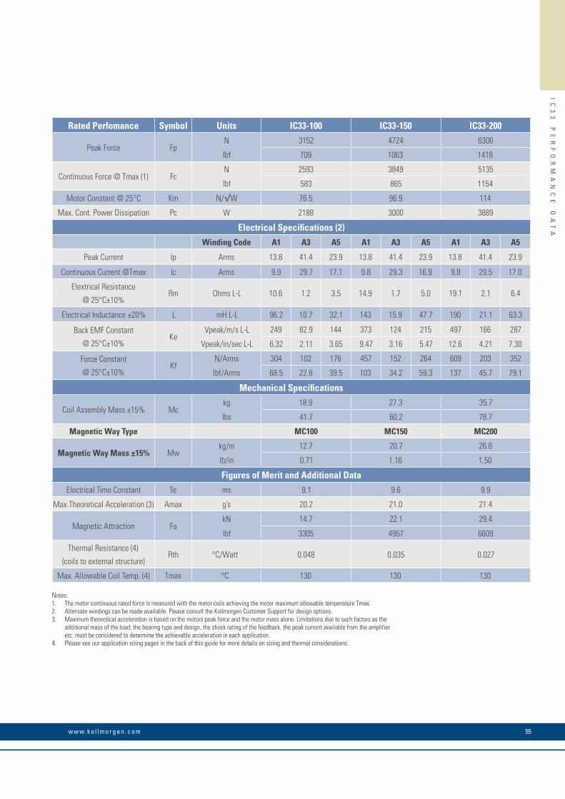
55w w w. k o l l m o r g e n . c o m
IC
33
P
ER
FO
RM
AN
CE
D
AT
A
Rated Perfomance Symbol Units IC33-100 IC33-150 IC33-200
Peak Force FpN 3152 4724 6306
lbf 709 1063 1418
Continuous Force @ Tmax (1) FcN 2593 3849 5135
lbf 583 865 1154
Motor Constant @ 25°C Km N/√W 76.5 96.9 114
Max. Cont. Power Dissipation Pc W 2188 3000 3889
Electrical Specifications (2)Winding Code A1 A3 A5 A1 A3 A5 A1 A3 A5
Peak Current lp Arms 13.8 41.4 23.9 13.8 41.4 23.9 13.8 41.4 23.9
Continuous Current @Tmax lc Arms 9.9 29.7 17.1 9.8 29.3 16.9 9.8 29.5 17.0
Elextrical Resistance
@ 25°C±10%Rm Ohms L-L 10.6 1.2 3.5 14.9 1.7 5.0 19.1 2.1 6.4
Electrical Inductance ±20% L mH L-L 96.2 10.7 32.1 143 15.9 47.7 190 21.1 63.3
Back EMF Constant
@ 25°C±10%Ke
Vpeak/m/s L-L 249 82.9 144 373 124 215 497 166 287
Vpeak/in/sec L-L 6.32 2.11 3.65 9.47 3.16 5.47 12.6 4.21 7.30
Force Constant
@ 25°C±10%Kf
N/Arms 304 102 176 457 152 264 609 203 352
lbf/Arms 68.5 22.8 39.5 103 34.2 59.3 137 45.7 79.1
Mechanical Specifications
Coil Assembly Mass ±15% Mckg 18.9 27.3 35.7
lbs 41.7 60.2 78.7
Magnetic Way Type MC100 MC150 MC200
Magnetic Way Mass ±15% Mwkg/m 12.7 20.7 26.8
lb/in 0.71 1.16 1.50
Figures of Merit and Additional DataElectrical Time Constant Te ms 9.1 9.6 9.9
Max.Theoretical Acceleration (3) Amax g’s 20.2 21.0 21.4
Magnetic Attraction FakN 14.7 22.1 29.4
lbf 3305 4957 6609
Thermal Resistance (4)
(coils to external structure)Rth °C/Watt 0.048 0.035 0.027
Max. Allowable Coil Temp. (4) Tmax °C 130 130 130
Notes:1. The motor continuous rated force is measured with the motor coils achieving the motor maximum allowable temperature Tmax.2. Alternate windings can be made available. Please consult the Kollmorgen Customer Support for design options.3. Maximum theoretical acceleration is based on the motors peak force and the motor mass alone. Limitations due to such factors as the additional mass of the load, the bearing type and design, the shock rating of the feedback, the peak current available from the amplifier etc. must be considered to determine the achievable acceleration in each application.4. Please see our application sizing pages in the back of this guide for more details on sizing and thermal considerations.

K O L L M O R G E N 56
IC
33
O
UT
LI
NE
D
RA
WI
NG
S
IC33 Outline Drawings
STANDARD LENGTH,SEE TABLE
THERMAL PROTECTION CONNECTOR: 2 PIN - MALE CONNECTOR FREE HANGING RECEPTACLE MOLEX P/N 43025-0200 2 FEMALE TERMINALS MOLEX P/N 43030-0010
MOTOR CONNECTOR: POSITRONIC P/N: CBD3W3M0000Z 3 PIN, MALE SHELL, SIZE 2MALE CONTACTS: POSITRONIC P/N: MS40--D 3 REMOVABLE MALE CONTACTS, SIZE 8
PIN 1
PIN 9
PIN 5
26.8(1.055)MAX.
#4-40 JACKNUT (2)(REMOVABLE FOR BULKHEAD MOUNTING)
COIL ASSEMBLY REF
HALL EFFECT CONNECTOR OPTION: POSITRONIC P/N: MD9M2000Z 9 PIN, MALEMATING CONNECTOR REFERENCE: POSITRONIC P/N: MD9F2000X SEE WIRE TABLE, PAGE 70
MATING CONNECTOR REFERENCE: POSITRONIC P/N: CBD3W3F0000X 3 FEMALE SOCKETS, SOLDER TYPE, SIZE 8, POSITRONIC P/N: FS40--D
SEE WIRE TABLE, PAGE 70
MATING CONNECTOR REFERENCE: MOLEX "MICRO-FIT 3.0" PLUG: 43020-0201 MALE TERMINALS: 43031-0010
SEE WIRE TABLE, PAGE 70
31.7(1.25)
16.2 (.637)
8.4 (.331)
COOLING OPTION: 1/8-27 NPT (FEMALE) 2 PL.
7.8(.308)
26.4(1.038)
32.0 (1.260)
STANDARD LENGTH,SEE TABLE
COIL ASSEMBLY REF
14.6(.575)
MOTOR CABLE
12
PIN1
PIN1
THERMAL
MOTOR
HALLEFFECT
HALL EFFECT MASSW/P* CONNECTOR: .07 KG (.15 LB) MAXW/C* CABLE: .03 KG (.07 LB) MAX
HALL EFFECT ASSEMBLY
75.0(2.953)6 PL.
M5 X 0.8 X 8 DP."N" NUMBER OF HOLESPER MOUNTING BAR
COIL ASSEMBLY
MAGNETWAY REF
51.1(2.012)
MOUNTING BAR7 PER MOTOR "C" DISTANCE BETWEEN
MOUNTING HOLES(SEE PAGE 69)
"B"
552. ±2 .6(21.740 ±.024)
OPTIONAL STAINLESSSTEEL MAGNET COVER
11.9(.469)
22.7(.894)
"A"
OPTIONAL COOLING(SEE OPTIONS BELOW)
FOR MOTOR CABLEAND HALL EFFECT MTG.
SEE OPTIONS BELOW
19.1(.750)
43.3 REF
Resultant airgap = 0.9mm
(.036) nominal (0.5mm (.020”)
minimum) when components
are set up to dimension “B”
in table below. (Please refer
to installation manual for
more detail)
Termination and Hall Effect Options
Notes:1. Dimensions in mm (inches)2. Tolerances unless otherwise specified: no decimal place ±0.8 (0.3) X decimal place ±0.1 (.004) XX decimal place ±0.05 (0.002)
Motor Coil Type
Coil WidthCooled
Dim "B" Dim "B" # Holes"A" without Cover w/ Magnet Cover "N"
IC33-030 65.0 (2.559) ± 1.0 (.04) ICXX-030 58.3±0.1 (2.295±.004) 58.6±0.1 (2.307±.004) 2IC33-050 85.0 (3.346) ± 1.0 (.04) ICXX-050 58.3±0.1 (2.295±.004) 58.6±0.1 (2.307±.004) 2IC33-075 110.0 (4.331) ± 1.0 (.04) ICXX-075 58.3±0.1 (2.295±.004) 58.6±0.1 (2.307±.004) 3IC33-100 135.0 (5.315) ± 1.0 (.04) ICXX-100 58.3±0.1 (2.295±.004) 58.6±0.1 (2.307±.004) 3IC33-150 185.0 (7.283) ± 1.0 (.06) ICXX-150 60.3±0.1 (2.374±.004) 60.6±0.1 (2.386±.004) 5IC33-200 235.0 (9.252) ± 1.0 (.06) ICXX-200 60.3±0.1 (2.374±.004) 60.6±0.1 (2.386±.004) 6
Connector OptionConnector Length
P1 400 (16)P2 200 (8)P3 100 (4)P4 1200 (48)
Flying Lead OptionLeads Length
C1 400 (16)C2 200 (8)C3 100 (4)C4 1200 (48)
Note:Cables exiting motor and hall effects are not dynamic flex cables. For high life flex extension cables, see page 72
Ironcore Water-Cooled Motors Series

57w w w. k o l l m o r g e n . c o m
IC
33
O
UT
LI
NE
D
RA
WI
NG
S
Notes

K O L L M O R G E N 58
IC
44
P
ER
FO
RM
AN
CE
D
AT
A
IC44 Performance Data
Rated Perfomance Symbol Units IC44-030 IC44-050 IC44-075
Peak Force FpN 1260 2101 3154
lbf 283 472 709
Continuous Force @ Tmax (1) FcN 1036 1711 2568
lbf 233 385 577
Motor Constant @ 25°C Km N/√W 39.9 56.8 74.0
Electrical Specifications (2)Winding Code A1 A2 A3 A1 A2 A3 A1 A2 A3
Peak Current lp Arms 13.8 27.6 55.2 13.8 27.6 55.2 13.8 27.6 55.2
Continuous Current @Tmax lc Arms 9.9 19.7 39.5 9.8 19.6 39.1 9.8 19.5 39.1
Elextrical Resistance
@ 25°C±10%Rm Ohms L-L 6.2 1.6 0.39 8.5 2.1 0.53 11.3 2.8 0.71
Electrical Inductance ±20% L mH L-L 41.3 10.3 2.6 66.1 16.5 4.1 97.3 24.3 6.1
Back EMF Constant
@ 25°C±10%Ke
Vpeak/m/s L-L 99.4 49.7 24.8 166 82.9 41.4 249 124 62.2
Vpeak/in/sec L-L 2.52 1.26 0.63 4.21 2.11 1.05 6.32 3.16 1.58
Force Constant
@ 25°C±10%Kf
N/Arms 122 60.9 30.4 203 102 50.8 305 152 76.2
lbf/Arms 27.4 13.7 6.8 45.6 22.8 11.4 68.5 34.2 17.1
Mechanical Specifications
Coil Assembly Mass ±15% Mckg 9.6 13.9 19.2
lbs 21.2 30.6 42.3
Magnetic Way Type MC030 MC050 MC075
Magnetic Way Mass ±15% Mwkg/m 5.4 7.5 10.1
lb/in 0.30 0.42 0.56
Figures of Merit and Additional DataElectrical Time Constant Te ms 6.7 7.8 8.6
Max.Theoretical Acceleration (3) Amax g’s 15.9 18.3 19.9
Magnetic Attraction FakN 5.9 9.8 14.7
lbf 1322 2203 3305
Thermal Resistance (4)
(coils to external structure)Rth °C/Watt 0.082 0.061 0.046
Max. Allowable Coil Temp. (4) Tmax °C 130 130 130
Notes:1. The motor continuous rated force is measured with the motor coils achieving the motor maximum allowable temperature Tmax.2. Alternate windings can be made available. Please consult the Kollmorgen Customer Support for design options.3. Maximum theoretical acceleration is based on the motors peak force and the motor mass alone. Limitations due to such factors as the additional mass of the load, the bearing type and design, the shock rating of the feedback, the peak current available from the amplifier etc. must be considered to determine the achievable acceleration in each application.4. Please see our application sizing pages in the back of this guide for more details on sizing and thermal considerations.
Ironcore Water-Cooled Motors Series

59w w w. k o l l m o r g e n . c o m
IC
44
P
ER
FO
RM
AN
CE
D
AT
A
Rated Perfomance Symbol Units IC44-100 IC44-150 IC44-200
Peak Force FpN 4202 6303 8407
lbf 945 1417 1890
Continuous Force @ Tmax (1) FcN 3457 5133 6916
lbf 777 1154 1555
Motor Constant @ 25°C Km N/√W 88.3 112 132
Electrical Specifications (2)Winding Code A1 A2 A3 A1 A2 A3 A1 A2 A3
Peak Current lp Arms 13.8 27.5 55.1 13.8 27.6 55.3 13.8 27.6 55.2
Continuous Current @Tmax lc Arms 9.9 19.8 39.5 9.8 19.6 39.2 9.9 19.8 39.6
Elextrical Resistance
@ 25°C±10%Rm Ohms L-L 14.1 3.5 0.88 19.8 5.0 1.2 25.5 6.4 1.6
Electrical Inductance ±20% L mH L-L 128 32.1 8.0 191 47.7 11.9 253 63.3 15.8
Back EMF Constant
@ 25°C±10%Ke
Vpeak/m/s L-L 331 166 82.9 497 249 124 663 332 166
Vpeak/in/sec L-L 8.42 4.21 2.11 12.6 6.32 3.16 16.8 8.42 4.21
Force Constant
@ 25°C±10%Kf
N/Arms 406 203 102 609 305 152 812 406 203
lbf/Arms 91.3 45.6 22.8 137 68.5 34.2 183 91.3 45.7
Mechanical Specifications
Coil Assembly Mass ±15% Mckg 25.0 36.2 47.4
lbs 55.1 79.8 104
Magnetic Way Type MC100 MC150 MC200
Magnetic Way Mass ±15% Mwkg/m 12.7 20.7 26.8
lb/in 0.71 1.16 1.50
Figures of Merit and Additional DataElectrical Time Constant Te ms 9.1 9.6 9.9
Max.Theoretical Acceleration (3) Amax g’s 20.4 21.1 21.5
Magnetic Attraction FakN 19.6 29.4 39.4
lbf 4406 6609 8855
Thermal Resistance (4)
(coils to external structure)Rth °C/Watt 0.036 0.026 0.020
Max. Allowable Coil Temp. (4) Tmax °C 130 130 130
Notes:1. The motor continuous rated force is measured with the motor coils achieving the motor maximum allowable temperature Tmax.2. Alternate windings can be made available. Please consult the Kollmorgen Customer Support for design options.3. Maximum theoretical acceleration is based on the motors peak force and the motor mass alone. Limitations due to such factors as the additional mass of the load, the bearing type and design, the shock rating of the feedback, the peak current available from the amplifier etc. must be considered to determine the achievable acceleration in each application.4. Please see our application sizing pages in the back of this guide for more details on sizing and thermal considerations.

K O L L M O R G E N 60
IC
44
O
UT
LI
NE
D
RA
WI
NG
S
IC44 Outline Drawings
STANDARD LENGTH,SEE TABLE
THERMAL PROTECTION CONNECTOR: 2 PIN - MALE CONNECTOR FREE HANGING RECEPTACLE MOLEX P/N 43025-0200 2 FEMALE TERMINALS MOLEX P/N 43030-0010
MOTOR CONNECTOR: POSITRONIC P/N: CBD3W3M0000Z 3 PIN, MALE SHELL, SIZE 2MALE CONTACTS: POSITRONIC P/N: MS40--D 3 REMOVABLE MALE CONTACTS, SIZE 8
PIN 1
PIN 9
PIN 5
26.8(1.055)MAX.
#4-40 JACKNUT (2)(REMOVABLE FOR BULKHEAD MOUNTING)
COIL ASSEMBLY REF
HALL EFFECT CONNECTOR OPTION: POSITRONIC P/N: MD9M2000Z 9 PIN, MALEMATING CONNECTOR REFERENCE: POSITRONIC P/N: MD9F2000X SEE WIRE TABLE, PAGE 70
MATING CONNECTOR REFERENCE: POSITRONIC P/N: CBD3W3F0000X 3 FEMALE SOCKETS, SOLDER TYPE, SIZE 8, POSITRONIC P/N: FS40--D
SEE WIRE TABLE, PAGE 70
MATING CONNECTOR REFERENCE: MOLEX "MICRO-FIT 3.0" PLUG: 43020-0201 MALE TERMINALS: 43031-0010
SEE WIRE TABLE, PAGE 70
31.7(1.25)
16.2 (.637)
8.4 (.331)
COOLING OPTION: 1/8-27 NPT (FEMALE) 2 PL.
7.8(.308)
26.4(1.038)
32.0 (1.260)
STANDARD LENGTH,SEE TABLE
COIL ASSEMBLY REF
14.6(.575)
MOTOR CABLE
12
PIN1
PIN1
THERMAL
MOTOR
HALLEFFECT
HALL EFFECT MASSW/P* CONNECTOR: .07 KG (.15 LB) MAXW/C* CABLE: .03 KG (.07 LB) MAX
HALL EFFECT ASSEMBLY
75.0(2.953)9 PL.
M5 X 0.8 X 8 DP."N" NUMBER OF HOLESPER MOUNTING BAR
COIL ASSEMBLY
MAGNETWAY REF
26.6(1.047)
MOUNTING BAR10 PER MOTOR "C" DISTANCE BETWEEN
MOUNTING HOLES(SEE PAGE 69)
"B"
728. ±2 .6(28.669 ±.024)
OPTIONAL STAINLESSSTEEL MAGNET COVER
11.9(.469)
22.7(.894)
"A"
OPTIONAL COOLING(SEE OPTIONS BELOW)
FOR MOTOR CABLEAND HALL EFFECT MTG.
SEE OPTIONS BELOW
19.1(.750)
43.3 REF
Resultant airgap = 0.9mm
(.036) nominal (0.5mm (.020”)
minimum) when components
are set up to dimension “B”
in table below. (Please refer
to installation manual for
more detail)
Termination and Hall Effect Options
Notes:1. Dimensions in mm (inches)2. Tolerances unless otherwise specified: no decimal place ±0.8 (0.3) X decimal place ±0.1 (.004) XX decimal place ±0.05 (0.002)
Motor Coil Type
Coil WidthCooled
Dim "B" Dim "B" # Holes"A" without Cover w/ Magnet Cover "N"
IC44-030 65.0 (2.559) ± 1.0 (.04) ICXX-030 58.3±0.1 (2.295±.004) 58.6±0.1 (2.307±.004) 2IC44-050 85.0 (3.346) ± 1.0 (.04) ICXX-050 58.3±0.1 (2.295±.004) 58.6±0.1 (2.307±.004) 2IC44-075 110.0 (4.331) ± 1.0 (.04) ICXX-075 58.3±0.1 (2.295±.004) 58.6±0.1 (2.307±.004) 3IC44-100 135.0 (5.315) ± 1.0 (.04) ICXX-100 58.3±0.1 (2.295±.004) 58.6±0.1 (2.307±.004) 3IC44-150 185.0 (7.283) ± 1.0 (.06) ICXX-150 60.3±0.1 (2.374±.004) 60.6±0.1 (2.386±.004) 5IC44-200 235.0 (9.252) ± 1.0 (.06) ICXX-200 60.3±0.1 (2.374±.004) 60.6±0.1 (2.386±.004) 6
Connector OptionConnector Length
P1 400 (16)P2 200 (8)P3 100 (4)P4 1200 (48)
Flying Lead OptionLeads Length
C1 400 (16)C2 200 (8)C3 100 (4)C4 1200 (48)
Note:Cables exiting motor and hall effects are not dynamic flex cables. For high life flex extension cables, see page 72
Ironcore Water-Cooled Motors Series

61w w w. k o l l m o r g e n . c o m
IC
44
O
UT
LI
NE
D
RA
WI
NG
S
Notes
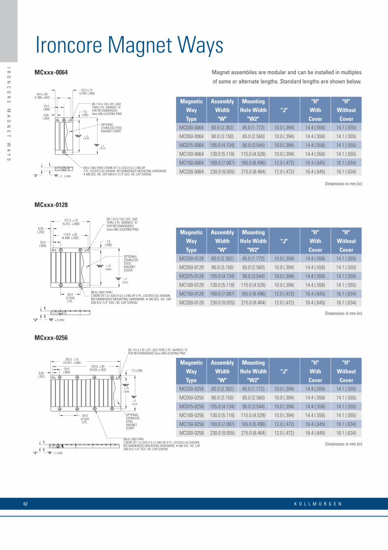
K O L L M O R G E N 62
IR
ON
CO
RE
M
AG
NE
T
WA
YS
Ironcore Magnet WaysMCxxx-0064
A A
7.5(.295)
Ø6.6 (.260) THRU C'BORE Ø11.0 (.433) X 6.2 (.246) DP.2 PL. LOCATED AS SHOWN. RECOMMENDED MOUNTING HARDWARE:• M6 SOC. HD. CAP DIN 912 (1/4" SOC. HD. CAP SCREW)
6.65(.262)
25.0(.984)
OPTIONALSTAINLESS STEELMAGNET COVER
63.3 ±.15(2.492 ±.006)50.0 ±.05
(1.968 ±.002)
"W"
"W2"
Ø5.110-5.135 (.201-.202)THRU 2 PL. MARKED "A"FOR RECOMMENDED5mm M6 LOCATING PINS
"J" "H"
Magnet assembiles are modular and can be installed in multiples
of same or alternate lengths. Standard lengths are shown below.
Magnetic Assembly Mounting"J"
"H" "H"Way Width Hole Width With WithoutType "W" "W2" Cover Cover
MC030-0064 60.0 (2.362) 45.0 (1.772) 10.0 (.394) 14.4 (.556) 14.1 (.555)
MC050-0064 80.0 (3.150) 65.0 (2.560) 10.0 (.394) 14.4 (.556) 14.1 (.555)
MC075-0064 105.0 (4.134) 90.0 (3.544) 10.0 (.394) 14.4 (.556) 14.1 (.555)
MC100-0064 130.0 (5.118) 115.0 (4.528) 10.0 (.394) 14.4 (.556) 14.1 (.555)
MC150-0064 180.0 (7.087) 165.0 (6.496) 12.0 (.472) 16.4 (.645) 16.1 (.634)
MC200-0064 230.0 (9.055) 215.0 (8.464) 12.0 (.472) 16.4 (.645) 16.1 (.634)
MCxxx-0128
Magnetic Assembly Mounting"J"
"H" "H"Way Width Hole Width With WithoutType "W" "W2" Cover Cover
MC030-0128 60.0 (2.362) 45.0 (1.772) 10.0 (.394) 14.4 (.556) 14.1 (.555)
MC050-0128 80.0 (3.150) 65.0 (2.560) 10.0 (.394) 14.4 (.556) 14.1 (.555)
MC075-0128 105.0 (4.134) 90.0 (3.544) 10.0 (.394) 14.4 (.556) 14.1 (.555)
MC100-0128 130.0 (5.118) 115.0 (4.528) 10.0 (.394) 14.4 (.556) 14.1 (.555)
MC150-0128 180.0 (7.087) 165.0 (6.496) 12.0 (.472) 16.4 (.645) 16.1 (.634)
MC200-0128 230.0 (9.055) 215.0 (8.464) 12.0 (.472) 16.4 (.645) 16.1 (.634)
MCxxx-0256
Magnetic Assembly Mounting"J"
"H" "H"Way Width Hole Width With WithoutType "W" "W2" Cover Cover
MC030-0256 60.0 (2.362) 45.0 (1.772) 10.0 (.394) 14.4 (.556) 14.1 (.555)
MC050-0256 80.0 (3.150) 65.0 (2.560) 10.0 (.394) 14.4 (.556) 14.1 (.555)
MC075-0256 105.0 (4.134) 90.0 (3.544) 10.0 (.394) 14.4 (.556) 14.1 (.555)
MC100-0256 130.0 (5.118) 115.0 (4.528) 10.0 (.394) 14.4 (.556) 14.1 (.555)
MC150-0256 180.0 (7.087) 165.0 (6.496) 12.0 (.472) 16.4 (.645) 16.1 (.634)
MC200-0256 230.0 (9.055) 215.0 (8.464) 12.0 (.472) 16.4 (.645) 16.1 (.634)
64.0(2.520)2 PL.
A
6.65(.262)
127.3 ±.15(5.012 ±.006)
A
114.0 ±.05(4.488 ±.002)
"W"
"W2"
7.5(.295)
25.0(.984)
±.3(.012)
±.10(.004)
OPTIONALSTAINLESSSTEELMAGNETCOVER
"J" "H" ±.2 (.008)
Ø5.110-5.135 (.201-.202)THRU 2 PL. MARKED "A"FOR RECOMMENDED5mm M6 LOCATING PINS
Ø6.6 (.260) THRUC'BORE Ø11.0 (.433) X 6.2 (.246) DP. 4 PL. LOCATED AS SHOWNRECOMMENDED MOUNTING HARDWARE: • M6 SOC. HD. CAPDIN 912 (1/4" SOC. HD. CAP SCREW)
64.0(2.520)6 PL.
A
255.3 ±.15(10.051 ±.006)
242.0 ±.05(9.528 ±.002)
A
"W2"
"W"
±.10(.004)
±.3(.012)
7.5 (.295)6.65(.262)
25.0(.984)
Ø6.6 (.260) THRUC'BORE Ø11.0 (.433) X 6.2 (.246) DP. 8 PL. LOCATED AS SHOWNRECOMMENDED MOUNTING HARDWARE: • M6 SOC. HD. CAPDIN 912 (1/4" SOC. HD. CAP SCREW)
OPTIONALSTAINLESSSTEELMAGNETCOVER
Ø5.110-5.135 (.201-.202) THRU 2 PL. MARKED "A"FOR RECOMMENDED 5mm M6 LOCATING PINS
"J" "H" ±.2 (.008)
Dimensions in mm (in)
Dimensions in mm (in)
Dimensions in mm (in)

63w w w. k o l l m o r g e n . c o m
IR
ON
CO
RE
M
AG
NE
T
WA
YS
AAAA A
1STMAGNET
ASSEMBLY
31.75(1.250)
6.75(.266)
64.0(2.520)
TYP BOLT MTG.
14.00(.551)
PIN LOC.RECOMMENDED
PIN Ø5 M6
2NDMAGNET
ASSEMBLY
3RDMAGNET
ASSEMBLY
PIN DATUM HOLES TO BE LOCATED ON SAME SIDE TO ENSURE CORRECT NORTH/SOUTH POLE ORIENTATION
RESULTANT GAP BETWEEN MAGNET ASSEMBLIES FROM PROPER PIN LOCATION. DO NOT BUTT MAGNET ASSEMBLIES.
MCxxx-0512
64.0(2.520)14 PL.
A
511.3 ±.15(20.130 ±.006)
498.0 ±.05(19.606 ±.002)
A
"W""W2"
±.3(.012)
±.10(.004)
7.5(.295)6.65
(.262)
25.0(.984)
Ø6.6 (.260) THRUC'BORE Ø11.0 (.433) X 6.2 (.246) DP.16 PL. LOCATED AS SHOWNRECOMMENDED MOUNTING HARDWARE:• M6 SOC. HD. CAP DIN 912 (1/4" SOC. HD. CAP SCREW)
"J"
"H" ±.2 (.008)
OPTIONAL STAINLESSSTEEL MAGNET COVER
Ø5.110-5.135 (.201-.202)THRU 2 PL. MARKED "A"FOR RECOMMENDED 5mm M6LOCATING PINS
Magnetic Assembly Mounting"J"
"H" "H"Way Width Hole Width With WithoutType "W" "W2" Cover Cover
MC030-0512 60.0 (2.362) 45.0 (1.772) 10.0 (.394) 14.4 (.556) 14.1 (.555)
MC050-0512 80.0 (3.150) 65.0 (2.560) 10.0 (.394) 14.4 (.556) 14.1 (.555)
MC075-0512 105.0 (4.134) 90.0 (3.544) 10.0 (.394) 14.4 (.556) 14.1 (.555)
MC100-0512 130.0 (5.118) 115.0 (4.528) 10.0 (.394) 14.4 (.556) 14.1 (.555)
MC150-0512 180.0 (7.087) 165.0 (6.496) 12.0 (.472) 16.4 (.645) 16.1 (.634)
MC200-0512 230.0 (9.055) 215.0 (8.464) 12.0 (.472) 16.4 (.645) 16.1 (.634)
Dimensions in mm (in)
M5 X .8 X 8 DP.NUMBER OF HOLESPER BAR "N" WILLVARY WITH MOTOR WIDTH
"C""L"
"S"
Typical Mounting Bar Lengths & Mounting Holes Tabulation
Magnet Way widths correspond to the mating coil
assembly width. Magnet Way assemblies are modular
and come in standard lengths: 64, 128, 256, 512 mm.
Multiple magnet assemblies can be installed to obtain
the desired length. Shown below is the method to mount
multiple assemblies.
Typical Installation of Multiple Ironcore Magnet Assemblies
Magnetic Number Spacing Mounting"S"Coil of Holes Between Holes Bar Length
Type "N" "C" "L"ICXX-030 2 16.0 (0.630) 30 (1.18) 7.0 (.276)
ICXX-050 2 36.0 (1.417) 50 (1.97) 7.0 (.276)
ICXX-075 3 32.0 (1.260) 75 (2.95) 5.5 (.217)
ICXX-100 3 36.0 (1.417) 100 (3.94) 14.0 (.551)
ICXX-150 5 32.0 (1.260) 150 (5.91) 11.0 (.433)
ICXX-200 6 36.0 (1.417) 200 (7.87) 10.0 (.394)
Dimensions in mm (in)
Dimensions in mm (in)
Dimensions in mm (in)
Dimensions in mm (in)

K O L L M O R G E N 64
WI
RI
NG
A
ND
O
UT
PU
T
Wiring and Output
Motor BEMF phases A,B,C relative to Hall effect devices
S1,S2,S3 with coil travel direction towards the motor output
cable assembly exit as shown below.
COIL ASSEMBLY MAGNET WAY
COIL TRAVEL DIRECTION
MOTOR OUTPUTCABLE
A
BC
A
BC
MOTOR WINDINGCONFIGURATION WITH
TRAVEL DIRECTIONAS SHOWN
Magnet pole pitch:
Both Ironcore (IC) and Ironless (IL) feature the same pole pitch, which is 32 mm (360 electrical degrees).
Motor Wire Table Hall Effect Wire Table Thermal Protection Wire TableSEE TABLE BELOW FOR AWG DIA 26 AWG 6.0 DIA (.24") Thermistor 26 AWG 3.8 (.15")
Color or Pin TransitionPin Number Wire No. Function Number Color Function Pin Color Point
1 Red ØA 1 Gray +5 VDC1 Black/White
120˚C (IC/ICD)
2 White ØB 2 Green S1 90˚C (IL)
3 Black ØC 3 Yellow S22 Black/White
120˚C (IC/ICD)
Connector Shell Grn/Yel GND 4 Brown S3 90˚C (IL)
Connector Shell Violet Shield 5 White Returnsee note 2
Shell Shield Shield
Note:1. The diagram above refers to both Ironless and Ironcore motors
IL WIRE TABLEWINDING CODE AWG APPROX. CBL. DIA.ALL (A1,A2,A3,A4) 18 5.6mm (.22 IN)
ICD WIRE TABLEWINDING CODE AWG APPROX. CBL. DIA.
ALL (A1 - A4) 22 5.1mm (.20 IN)
IC WIRE TABLE NON-COOLEDWINDING CODE AWG APPROX. CBL. DIA.
A1 18 5.6mm (.22 IN)
A2 18 5.8mm (.22 IN)
A3 14 8.9mm (.27 IN)
A5 18 5.8mm (.22 IN)
A6 14 6.9mm (.27 IN)
A7 10 7.9mm (.31 IN)
IC WIRE TABLE COOLED (AC)WINDING CODE AWG APPROX. CBL. DIA.
A1 18 5.6mm (.22 IN)
A2 14 8.9mm (.27 IN)
A3 10 7.9mm (.31 IN)
A5 14 8.9mm (.27 IN)
A6 12 7.9mm (.31 IN)
Notes:1. Ground and shield connection at shell: first make/last break2. TIC-X extender cable is shielded

65w w w. k o l l m o r g e n . c o m
WI
RI
NG
A
ND
O
UT
PU
T
ta tr td tdw t, time
To size a Linear Motor, you will need to:1. Define a Move Profile2. Define the Load3. Size the Motor and the Amplifier
From the move profile, we can calculate the maximum speed and the maximum acceleration/deceleration. From the load we can calculate all of the forces at constant speed and using the move profile all the dynamic forces during acceleration and deceleration. Once a motor is selected, the weight of the moving parts of the motor are added to the moving weight to calculate a total Peak Force and a total RMS force. The motor should be able to deliver the peak force and the calculated RMS force should be higher than the continuous force to ensure a known safety margin. The coil temperature rise can also be calculated to ensure that it is lower than the intended maximum temperature rise.
The maximum bus voltage and continuous and peak current can also be calculated and compared to the selected amplifier to be sure the calculated performances can be achieved.
1. Move Profile
Triangular/Trapezoidal
V, Velocity
Units
SI EnglishSm - Move displacement meters inchesta - Acceleration Time seconds secondstr - Time run at constant speed seconds secondstd - Deceleration Time seconds secondstdw - Dwell Time seconds secondsVm - Max Velocity meter inches/secAm - Acceleration meter/sec2 inchesDm - Deceleration meter/sec2 inches
example: Move 0.1 meter in 100 msec assuming ta = td and tr =0,
(assume triangular move)
Max Speed: Vm = 2 • Sm / ( ta + td + 2 • tr ) Vm = 2 • 0.1 / ( 100E-3 ) m/s2
= 2 meter/sec
Max Acceleration/Deceleration Acceleration Am = Vm / ta Am = 2 / 50E-3 m/s2
= 40 meter/sec2
Am “g” = Am/9.81 m/s2
a (g) = 40 / 9.81 = 4.08 g
Deceleration Dm = Vm/td
Dm = 2/50E-3 m/s2
= 40 meter/sec2
Dm “g” = Dm/9.81 m/s2
d(g) = 40/9.81 = 4.08 g
2. Load Units SI EnglishFext - External Force only N lbf (Cutting force, etc.)Facc - Acceleration Force only N lbfFr - Run Force at constant speed N lbfFdec - Deceleration Force only N lbfFam - Max. Acceleration Force N lbfFdm - Max. Deceleration Force N lbfFdw - Dwell Force N lbfFrms - RMS Force N lbfw- Coefficient of Friction – – (bearing support)Ml - Load Mass kg lbsMc - Coil Mass kg lbsMcb - Counterbalance Mass kg lbsFa - Magnetic Attraction Force N lbfCB - Counterbalance of load in % – –q - Angle of Linear Displacement with horizontal (0°= horizontal, 90° vertical) degrees degreesg - Gravity coefficient 9.81 m/s2 386 in/s2
n - Number of motors in parallel – –

K O L L M O R G E N 66
HI
GH
F
LE
X
CA
BL
E
SE
TS
High Flex Cable Sets
Dimensions in mm (in)
High Flex Cables for Use with AKD
High Flex Cables for Generic Applications
Dimensions in mm (in)
Features
• High Flex cable designed for dynamic, continuous flexing applications• Cable track compatible• Molded, high reliability connectors• Oil resistant PVC jacket• 105°C / 600V motor cable, 105°C / 300V Hall effect and thermal sensor cable• CE compliant, fully shielded low impedance cable and connectors• Fully tested, color coded, shipped with schematics• Complete cable system for simple and reliable plug-and-play installation
Standard lengths of 1, 3, 6, 9, 12 and 15 meters available. For other lengths, consult Kollmorgen Customer Support.
Note: ACI-AKD-A for use with Heidenhain Encoders. ACI-AKD-B for use with Renishaw Encoders.
*For cable configuration please contact your responsible KOLLMORGEN contact

67w w w. k o l l m o r g e n . c o m
AP
PL
IC
AT
IO
N
SI
ZI
NG
Application SizingBASIC FORMULAS*:
We assume a general case where we have n motors solidly coupled
pushing the load and a possible counterbalance weight Mcb
(Mostly for vertical displacement).
Example of Coefficient of Friction µ:
Counterbalance Weight:
Mcb = Ml • CB/100
Acceleration Force only:
Facc = [(Ml /n) • (1 + CB/100) + Mc] • Am
Run Force at constant speed:
Fr = (Ml /n + Mc) • g • SIN(q) + m • COS(q) - (Mcb/n) • g +
Fa • µ + Fext/n
Deceleration Force only:
Fdec = [(Ml /n) • (1 + CB/100) + Mc] • Dm
Maximum Acceleration Force:
Fam = Facc + Fr
Maximum Deceleration Force:
Fdm = Fdec - Fr
Dwell Force:
Fdw = (Ml /n+Mc) • g • [SIN(q)] - (Mcb/n) • g
RMS Force:
Frms = Fam2 • ta + Fr
2 • tr + Fdm2 • td + Fdw
2 • tdw
ta + tr + td + tdw
* All calculations are given in SI units. For English units use weight in lbs instead of mass • g.
3. SIZE THE MOTOR AND AMPLIFIER
example:
Assume same move as above with a Dwell Time of 50 ms.
Frms = (20.05)2•(50E-3) + (19.95)2•(50E-3)
100E-3 + 50E-3
Frms = 16.3 N
Motor Sizing: If we select an ironless motor for smoothest possible move we can use Motor IL060-30A1. This motor has a coil mass of 0.21 kg and no attractive force. By adding that weight in equations above, we need an additional Force of 0.21• 40 • 0.01= 0.084 N. So Peak Force is 20.05 + 0.08 = 28.45 N and RMS force: 23.19 N. This motor will have a safety factor of (38-23.19)•100/38 = 39%.
Sizing the Amplifier : Units
Linear bearing w/ balls 0.002 - 0.004
Linear bearing w/ rollers 0.005
Steel on oiled steel 0.06
Steel on dry steel 0.2
Steel on concrete 0.3
Moving Weight: Ml = 0.5kg
Number of Motors: n = 1
Horizontal Move: q = 0
Counterbalance Force: Mcb = 0
External Force: Fext = 0Friction Coefficient: m = 0.01
Run Force at Constant Speed: Fr = 0.5 • 9.81 •0.01=0 .05 N
Acceleration Force only: Fa = 0.5 • 40 = 20 N
Deceleration Force only: Fd = 0.5 • 40 = 20 N
Maximum Accel Force: Fam = 20 + 0.05 = 20.05 N
Maximum Decel Force: Fdm = 20 - 0.05 =19.95 N
Rms Force:
SI English
Ia - Max Acceleration Current A A
Ir - Run Current A A
Id - Max Deceleration Current A A
Idw - Dwell Current A A
Irms - RMS Current A A
Kf - Force Constant N/A lbf/A
Rm - Motor Electrical Resistance Ohms L-L Ohms L-L
Ke - Back EMF Constant Vpeak/m/s Vpeak/in/s
Vbus - Bus Voltage VDC VDC
L - Electrical Inductance H L-L H L-L
Max Acceleration Current: Ia = Fam/Kf
Run Current at constant Speed: Ir = Fr/Kf
Max Deceleration Current only: Id = Fdm/Kf
Dwell Current: Idw = Fdw/Kf
RMS Current: Irms = Frms/Kf
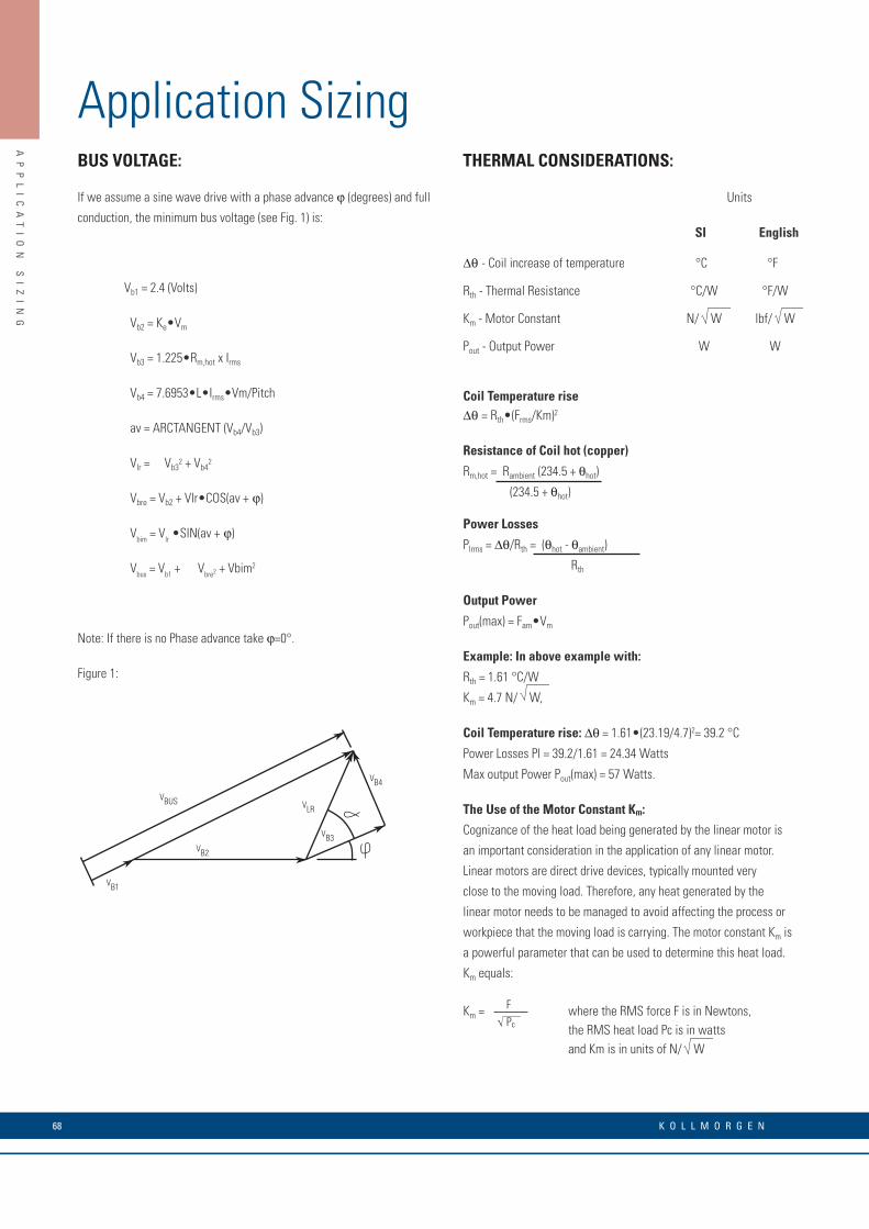
K O L L M O R G E N 68
AP
PL
IC
AT
IO
N
SI
ZI
NG
BUS VOLTAGE:
If we assume a sine wave drive with a phase advance j (degrees) and full
conduction, the minimum bus voltage (see Fig. 1) is:
Vb1 = 2.4 (Volts)
Vb2 = Ke•Vm
Vb3 = 1.225•Rm,hot x Irms
Vb4 = 7.6953•L•Irms•Vm/Pitch
av = ARCTANGENT (Vb4/Vb3)
Vlr = Vb32 + Vb4
2
Vbre = Vb2 + Vlr•COS(av + j)
Vbim = Vlr •SIN(av + j)
Vbus = Vb1 + Vbre2 + Vbim2
Note: If there is no Phase advance take j=0°.
Figure 1:
THERMAL CONSIDERATIONS:
Units
SI English
∆q - Coil increase of temperature °C °F
Rth - Thermal Resistance °C/W °F/W
Km - Motor Constant N/ W lbf/ W
Pout - Output Power W W
Coil Temperature rise ∆q = Rth•(Frms/Km)2
Resistance of Coil hot (copper)
Rm,hot = Rambient (234.5 + qhot)
(234.5 + qhot)
Power Losses
Plrms = ∆q/Rth = (qhot - qambient)
Rth
Output Power
Pout(max) = Fam•Vm
Example: In above example with:
Rth = 1.61 °C/W
Km = 4.7 N/ W,
Coil Temperature rise: ∆q = 1.61•(23.19/4.7)2= 39.2 °C
Power Losses Pl = 39.2/1.61 = 24.34 Watts
Max output Power Pout(max) = 57 Watts.
The Use of the Motor Constant Km: Cognizance of the heat load being generated by the linear motor is
an important consideration in the application of any linear motor.
Linear motors are direct drive devices, typically mounted very
close to the moving load. Therefore, any heat generated by the
linear motor needs to be managed to avoid affecting the process or
workpiece that the moving load is carrying. The motor constant Km is
a powerful parameter that can be used to determine this heat load.
Km equals:
Km = where the RMS force F is in Newtons, the RMS heat load Pc is in watts and Km is in units of N/ W
VB4
VBUS
VB1
VB2
VB3
VLR
FPc
Application Sizing

69w w w. k o l l m o r g e n . c o m
AP
PL
IC
AT
IO
N
SI
ZI
NG
The motor constant, KM, allows us to determine motor performance
capabilities such as shown in the following two examples. In the first
example, we use KM to calculate, for a given force, how many watts of
generated heat are dissipated by the motorís coil assembly. In the second,
we use KM to determine the maximum RMS force developed by the motor
when the dissipated power is limited to some value.
1. An application requires a continuous thrust force of 200 Newtons. The
IC11-050 ironcore motor is a good candidate, having a continuous force
rating of 276 Newtons and a KM of 32.0 N/W. Therefore, since resistance
rises 1.405 times at 130°C from the ambient value at 25°C, and since
resistance is the square root denominator of KM, we must write our
equation as follows,
Force =
200 =
Watts = 54.9
This value of watts is the power or heat generated by the motor. It is
interesting to note that for the same application, a larger IC11-100
ironcore motor, with a KM of 49.1 N/ W, would dissipate only 23.3 watts
for the same force, F.
2. The same application requires that no more than 45 watts are to be
dissipated by the motor into the surrounding structure and environment.
What is the maximum RMS force that the IC11-050 motor may produce
while not exceeding this power limit?
Maximum RMS Force = 45 = 181 N
Therefore, if the motor delivers no more than 181 N of thrust
force on an RMS basis, then this same motor will not dissipate
more than 45 watts.
Continuous Force Fc as a Function of Ambient Temperature
In our data sheets the continuous rated force Fc is the RMS force that the
motor can supply continuously 100% of the time, assuming the ambient
temperature is 25 degrees C and with the coils achieving a maximum
temperature of 130 degrees C. At higher (or lower) ambient temperatures,
the Fc of the motor must be adjusted by a factor that is determined by the
following equation:
Factor =
where qAmb = Ambient Temperature
This factor vs. ambient temperature works out as:
5 °C 10 15 20 25 30 35 40 45
1.091 1.069 1.047 1.024 1 0.976 0.951 0.926 0.900
(130 -qAmb )
105
KM
Factor
32.0
1.405Watts
Power (dissipated)
32.0
1.405
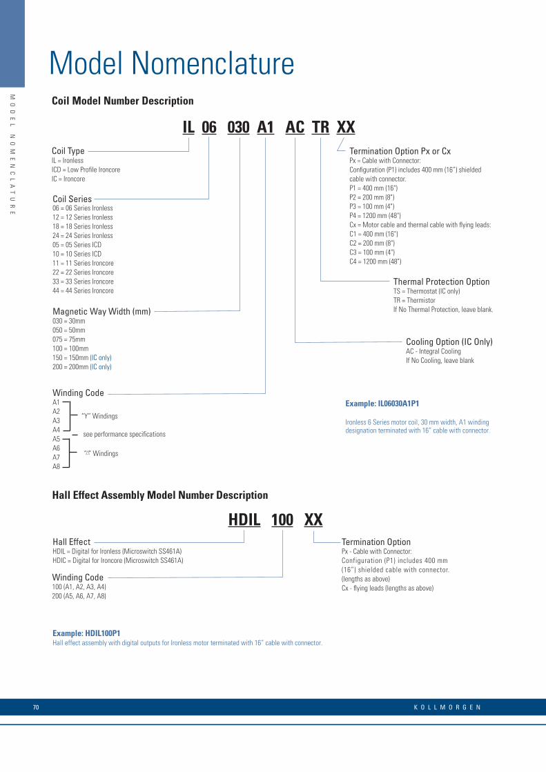
K O L L M O R G E N 70
MO
DE
L
NO
ME
NC
LA
TU
RE
Model Nomenclature
Hall Effect HDIL = Digital for Ironless (Microswitch SS461A) HDIC = Digital for Ironcore (Microswitch SS461A)
Example: HDIL100P1 Hall effect assembly with digital outputs for Ironless motor terminated with 16” cable with connector.
Winding Code 100 (A1, A2, A3, A4) 200 (A5, A6, A7, A8)
Termination Option Px - Cable with Connector: Configuration (P1) includes 400 mm (16”) shielded cable with connector. (lengths as above) Cx - flying leads (lengths as above)
Hall Effect Assembly Model Number Description
Coil Series 06 = 06 Series Ironless 12 = 12 Series Ironless 18 = 18 Series Ironless 24 = 24 Series Ironless 05 = 05 Series ICD 10 = 10 Series ICD 11 = 11 Series Ironcore 22 = 22 Series Ironcore 33 = 33 Series Ironcore 44 = 44 Series Ironcore
Termination Option Px or Cx Px = Cable with Connector: Configuration (P1) includes 400 mm (16”) shielded cable with connector. P1 = 400 mm (16") P2 = 200 mm (8") P3 = 100 mm (4") P4 = 1200 mm (48") Cx = Motor cable and thermal cable with flying leads: C1 = 400 mm (16") C2 = 200 mm (8") C3 = 100 mm (4") C4 = 1200 mm (48")
Coil Type IL = Ironless ICD = Low Profile Ironcore IC = Ironcore
Magnetic Way Width (mm) 030 = 30mm 050 = 50mm 075 = 75mm 100 = 100mm 150 = 150mm (IC only) 200 = 200mm (IC only)
Thermal Protection Option TS = Thermostat (IC only) TR = Thermistor If No Thermal Protection, leave blank.
Cooling Option (IC Only)AC - Integral Cooling If No Cooling, leave blank
Example: IL06030A1P1
Ironless 6 Series motor coil, 30 mm width, A1 winding designation terminated with 16” cable with connector.
Winding Code A1 A2 A3 A4 A5 A6 A7 A8
see performance specifications
“Y” Windings
“ ” Windings
Coil Model Number Description
IL 06 030 A1 AC TR XX
HDIL 100 XX
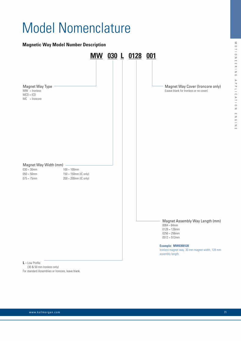
71w w w. k o l l m o r g e n . c o m
MO
TI
ON
EE
RI
NG
A
PP
LI
CA
TI
ON
E
NG
IN
E
Model NomenclatureMagnetic Way Model Number Description
Magnet Assembly Way Length (mm) 0064 = 64mm 0128 = 128mm 0256 = 256mm 0512 = 512mm
Magnet Way Type MW = Ironless MCD = ICD MC = Ironcore
Magnet Way Width (mm) 030 = 30mm 100 = 100mm 050 = 50mm 150 = 150mm (IC only) 075 = 75mm 200 = 200mm (IC only)
Example: MW0300128 Ironless magnet way, 30 mm magnet width, 128 mm assembly length.
L = Low Profile (30 & 50 mm Ironless only) For standard Assemblies or Ironcore, leave blank.
Magnet Way Cover (Ironcore only)(Leave blank for Ironless or no cover)
MW 030 L 0128 001

© 2010 Kollmorgen Corporation. All rights reserved. KM_C_00069_RevA_UK Specifications are subject to change without notice. It is the responsibility of the product user to determine the suitability of this product for a specific application. All trademarks are the property of their respective owners.
About Kollmorgen
Kollmorgen is a leading provider of motion systems and components for machine builders. Through world-class knowledge in motion, industry-leading quality and deep expertise in linking and integrating standard and custom products, Kollmorgen delivers breakthrough solutions that are unmatched in performance, reliability and ease-of-use, giving machine builders an irrefutable marketplace advantage.
For assistance with your application needs visit www.kollmorgen.com for a global contact list.
Application Centers
Global Design & Manufacturing
Global Manufacturing
San JoseSanta Barbara
Tijuana
Radford
Fond du LacMarengo
Lausanne
Ratingen
StockholmSäro
BrnoMilan
Mumbai
Kluang
Hong Kong
Shanghai
BeijingTianjin
NagoyaTokyo
KOLLMORGEN Europe GmbH Pempelfurtstraße 140880 RatingenGermanyPhone: +49 (0) 2102 9394 0 Fax: +49 (0) 2102 9394 3155
Seoul
Sao Paulo