koden radar 3210&3220
DESCRIPTION
MANUALTRANSCRIPT

L rcDENSERVICE MANUAL
MARINE RADAR
!>
I
L
IIlf,:
' '--z-
r
93841 562

7
tI
PRECAIITIONS
1. HIGH VOLTAGE WARNING
At severa l po ints in the scanner uni t and d lsp lay CRT mount of theradar , the re a re h igh vo l tages enough to k i11 a person coming in todi rect contact wi th thern. Al though the equlpment 1s designed toavoid danger in ord inary operat ion, care should be taken dur ing thema in tenance works ins ide the un i t s . Turn o f f the sh ip rs ma in sw iLchwhen checking the c i rcu i ts or replac ing components. Even af ter theradar i s sw i t ched o f f , some capac i to rs may take severa l m inu tes Lod ischarge . Be fo re touch ing the magne t ron and /o r CRT HV c i rcu i t s ,make su re to g round the capac i to rs w i th a c l i p co rd o r the 1 lke .
2. MICROWAVE HAZARI)
T a k e c a r e t o a v o i d p o s s i b l e h a r m f u l e f f e c t s o f m i - c r o w a v e r a d i a t i o nf r o m t h e r a d a r t o a h u m a n b o d y . T h e e y e s a r e p a r t i c u l a r l y v a l n e r -a b l e t o m i c r o w a v e . N e v e r l o o k d i r e c t l y i n t o a n o p e n w a v e g u i d e r a d i -a t i n g t h e p o w e r . R a d a r a n d o t h e r R . F . r a d i a t i o n s c a n u p s e t s o m ec a r d i a c p a c e m a k e r s . I f a u s e r o f c a r d i a c p a c e m a k e r s u s p e c t s a m u 1 -func t ion , tu rn o f f the equ ipment and leave the v ic in i ty o f Lhe an-tenna i rnmed ia te ly . Whenever i t i s necessary to work on the scannerun i t , a lways se t the cont ro ls to STANDBY or RADAR OFF.
3. FI]SES
B e f o r e s t a r t i n g t h e r a d a r , c o n f i r m t h a t p r o p e r l y r a L e d m a i n f u s e sa c c o r d i n g t o t h e s h i p ' s m a i n v o l t a g e a r e u s e d . T h e r a t e d m a l n a n dother fuses fo r MD-3210 and MD-3220 are l i s ted be low.
. \ :
(a ) Ma in fuse
(b ) CRT HV (See No te )
(c ) Modu la to r HV
(d) An tenna d r i vemoto r
4. MAGNETRON PREHEATING
Ship's Main
T2 VDC24 VDC
Either
E i the r
E i the r
I'tD-32r0
1 5 A8 A1 Al- tl
0 . 3 A? 1 < AJ . L J N
tfi-3220
N o t a p p l i c a b l e1 0 A
i A
0 . 5 A
3 . 1 5 A
B e f o r e t r a n s m i t t i n g t h e m i c r o w a v e f o r t h e f i r s t t r a n s m i s s i o n a f t e ri n s t a l l a t l o n , o r a f t e r 2 m o n t h s o r o v e r p a u s e o f o p e r a t i o n , p r e h e a tthe magnet ron more than 30 minu tes by keep ing the radar in STANDBYc o n d i t i o n .
Note : CRT HV fuse is no t used fo r the un i t o f ser ia l numbers shownbe1ow, equ ipped w i th power supp ly I ' {D-32I0 /3220-6000M3.
MD-3210: No. 2100659 and thereaf terMD-3220: No. 3220336 and thereaf ter
MD-32I0/ 3220 Serv ice Manual-Ol

t -II
lf --
,J
Marine Radar MD-3210 / SZZOINDEX
Page
PRECAUT IONS1. GENERAL l - i
1 . 1 M a j o r P e r f o r m a n c e s1 . 1 . 1 A n L e n n a u n i t I - 21 . I . 2 D i s p l a y u n i t I - 2
1 . 1 . 3 P o w e r s u p p l y 1 - 3
1 . 2 C o m p o s i t i o nr . 2 . 1 M D - 3 2 r 0 / 3 2 2 0 . . . . . . . . . . . . . . r - 4I . 2 . 2 O p t i o n a l e q u i p m e n t 1 - 5
1 . 3 S y s t e m C o n f i g u r a t i o n o f M D - 3 2 I 0 / 3 2 2 0 . . . . 1 - 6
I .4 In te rconnecL ion o f MD-32 I013220 I -7
1 . 5 M o d i f i c a t i o n o f S p e c l f i c a t i o n s1 . 5 . 1 J u m p e r p i n s e t t i n g 1 - 8
L . 5 . 2 D I P s w i t c h s e t t i n g 1 - B
2. FUNCTION OF EACH UNIT2 . I A n t e n n a U n i t . . . . 2 - I
2 . f . 1 A e r i a 1 2 - I
2 , I , 2 A n t e n n a n o t o r 2 - 2
2 . I . 3 S H F a n d A Z I g e n e r a t o r s . , . . 2 - 2
2 . I . 4 T r a n s m i t t i n g s e c t i o n 2 - 3
2 . I . 5 D u p l e x i n g a s s e m b l y 2 - 5
2 . I . 6 R e c e i v i n g s e c t j - o n 2 - 5
2 . 2 D l s p l a y U n i t 2 - l
2 .2 .1 Power supply (MD-32 10/3220-6000 ) . . 2-7
2 . 2 . 2 L o g i c s e c t i o n . . . . . 2 - 9( i ) L o g i c u p p e r ( M D - 3 2 1 0 - 7 0 0 0 ) . . . . . . 2 - 9(2 ) Log ic lower (MD-3210-7100) 2 -L3
2 . 2 . 3 C o n t r o l p a n e l ( M D - 3 2 1 0 - 7 2 0 0 ) . . . . . . . . 2 - I 8
3. ADJUST]'{ENT3 . 1 L o c a t i o n o f C o n t r o l s . . . . . . . . . . . . . . 3 - i
3 .2 Ad jus t rnen t A f te r Ins ta l l a l i on 3 - l
3 . 2 . 1 T u n i n g 3 - 1
3 , 2 . 2 P r e s e t g a i n ( n o i s e 1 e v e 1 ) . . . . . . . . . . . . . 3 - 2
3 . 2 . 3 S T C , . . . . . . . 3 - 2
3 . 2 . 4 T r i - g g e r d e l a y . . . . . 3 - z
3 . 2 . 5 S H F a n d b e a r i n g . . . . . . . . . . . . . . . . 3 - 33 .3 Ad jus tment o f An tenna Un i t 3 -3
3 .4 Ad jus t rnen t o f D isp lay3 . 4 . 1 P o w e r s u p p l y ( M D - 3 2 L 0 / 3 2 2 0 - 6 0 0 0 ) . . . . . . 3 - 3
3 . 4 . 2 L o g i c u p p e r ( M D - 3 2 1 0 - 7 0 0 0 ) 3 - 53 . 4 . 3 l o g i c l o w e r ( M D - 3 2 i 0 - 7 1 0 0 ) . . . . . . . . . . . . . . . . 3 - 5
3 .4 .4 CRT un i t (P \^ /D- i050A/PWD-1051A) 3 -6
1 -
4. WAVEFORMS4 . I A n t e n n a U n i t
4 . t . 1 M R T - 1 3 3 ( M D - 3 2 1 0 ) . . . . . . . . . . . .4 . L . 2 m T - 1 3 4 ( M D - 3 2 2 0 )
4 . 2 D i s p l a y u n i t4 . 2 . 1 P o w e r s u p p l y4 . 2 . 2 L o g i c u p p e r4 . 2 . 3 L o g i c l o w e r
5. REPLACEMENT OF MAJOR COMPONENTS5 . 1 A n t e n n a u n i t
5 . 1 . 1 D i s m o u n t i n g t r a n s m i t l e r / r e c e i v e r ( T R ) u n i t5 . I . 2 R e p l a c e m e n t o f T R u n i t c o m p o n e n t s5 . 1 . 3 R e p l a c e m e n t o f S C O N . . . . . . . . . . . . . . . .5 . 1 . 4 R e p l a c e m e n t o f m o t o r b r u s h5 . 1 . 5 R e p l a c e m e n t o f m o t o r
5 . 2 D i s p l a y u n l t5 . 2 . 1 C o n t r o l p a n e l ( M D - 3 2 1 0 - 7 2 0 0 ) . .5 . 2 . 2 L o g i c u p p e r ( M D - 3 2 1 0 - 7 0 0 0 ) a n d
log ic lower (MD-3210-7100)5 . 2 . 3 P o w e r s u p p l y ( M D - 3 2 1 0 1 3 2 2 0 - 6 0 0 0 ) . .5 . 2 . 4 C R T u n i t
6. TROUBLESHOOTING6. I T roub leshoo t ing by Observ ing D isp lay6 .2 Opera t ion Con t ro l T roub leshoo t ing . . . .6 . 3 A n t e n n a T r o u b l e s h o o t i n g . . . . . . . . . . . . . . .
7 . DIAGRAMS7 . L C i r c u i t D i a g r a m . . . . . . . . . . . .7 ,2 Draw ings fo r pa r ts loca t ion
8. PARTS LIST8 . 1 E l e c t r i c a l P a r t s
8 . 1 . 1 A n r e n n a u n i r M R T - 1 3 3 ( 1 0 k W )8 . I . 2 A n t e n n a u n i t M R T - 1 3 4 ( 2 5 k W )8 . 1 . 3 D i _ s p l a y u n i r M R D - 6 2 / M R D - 6 8 . . . . . . . . . . .
8 . 2 M e c h a n i c a l P a r t s8 . 2 . 1 A n t e n n a u n i t M R T - 1 3 3 ( 1 0 k W ) . . o .8 .2 .2 An lenna un i r I '&T- r34 Q5 kW) . . . .8 .2 .3 D isp lay un i r MRD-62 /MRO-OS
8 . 3 E x p l o d e d V i e w8 . 3 . 1 A n t e n n a u n i t8 . 3 . 2 D i s p l a y u n i t
: f J + J f * * * * : f * : f *
4-I4-3
4-4+ - J
4-5
J _ L
< tJ - L
J _ L
5-4) - +
J - +
5 - 6
- a
) - l
5-86 - 16 - 16-46 - 7
-7 1t - I
/ - / - 4
8-18-8
8 - 1 8
8-288-3 18-32
8-3s8-42
I
2

1 .
SERVICE MANUALfor
MARINE RADAR MD_3210 / 3220
GENERAL
K o d e n M D - 3 2 L 0 / 3 2 2 0 s e r i e s i s a h i g h l y e f f i c i e n t m a r i n e r a d a r w h i c h c o n f o r mL h e I M O s t a n d a r d s L o b e u s e d f o r a p r i m a r y r a d a r o f f i s h i n g b o a l , w o r k b o a l ,a n d o t h e r v e s s e l l e s s t h a n 1 0 , 0 0 0 g r o s s w e i g h t L o n s . T h e s y s l e m c o n s i s t s o fo n l y t w o u n i t s , i . e . t h e a n L e n n a a n d d i s p l a y . E x c e p l f o r m a g n e t r o n a n d C R T ,a l l L h e a c t i v e c o m p o n e n l s a r e s o l i d s t a t e w h i c h m a i n t a i n h i g h r e l i a b i l i L ya n d m a i n L e n a b i l i t v .
T h e r a d a r d i s p l a y u s e s a 2 0 - i n c h d i a g o n a l h i g h r e s o l u t i o n g r e e n m o n o c h r o m eC R T . I t e m p l o y s X - Y c o o r d i n a t e s t o d i g i t a l l y p r o c e s s t h e r a d a r i n f o r m a t i o na n d d i q n l a v L h e i m a g e w i t h a b u i l t - i n m i c r o p r o c e s s o r . T h e r a d a r s c r e e n i sd i v l d e d i n t o n u m b e r o f p i c t u r e e l e m e n l s , s o c a 1 l e d p i x e l s . E a c h p i x e l i sa s s i g n e d w i l h X - Y c o o r d i n a t e s w h i c h c o r r e s p o n d s t o L h e m e m o r y a d d r e s s . T h er a d a r r e t u r n e c h o e s i n p o l a r c o o r d i n a t e s f o r e v e r y p u l s e L r a n s m i s s i o n a r ec o n v e r L e d i n l o X - Y c o o r d i n a t e s i - n a c c o r d a n c e w i L h L h e d i s t a n c e a n d a z i m u t h .T h e d i s t a n c e i s o b l a i n e d f r o m t h e t i m e d u r a l i o n b e t w e e n t r a n s m i s s i o n a n dr e c e p l l o n o f p u l s e , w h i l e t h e a z i m u t h i s g i v e n f r o m t h e a n t e n n a u n i l . T h ec o o r d i n a t e s c o n v e r t e d d a l a i s s t o r e d i n L o m e m o r y a n d L h e n r e a d o u l t o d i s -p l a y L h e i r n a g e i n a r a s t e r s c a n m e l h o d a l l o w i n g t h e p i c L u r e t o b e m o n i t o r e db y p 1 u r a 1 p e r s o n s u n d e r d a y l i g h t c o n d i L i o n w i t h o u t v i e w i n g h o o d . A c c o r d i n gt o t h e L r a n s r n i t L i n g p o w e r , s y s t e m i s c l a s s i f i e d i n t o L w o m o d e l s a s b e 1 o w .
ar^ ' l
MD-321 0MD-3220
Antenna unit
10 kl,J25 kW
A n t e n n a u n i L c o n s j - s l s o f a 6 - f o o l s l o L t e d a r r a y a e r i a l , a n t e n n a d r l v eu n i l , a n d t r a n s c e i v e r u n l t . T h e s l o t t e d a r r a y a e r i a l i s c o n t a i n e d i n ar e i n f o r c e d p l a s t i c c y l i n d r i c a l c a s e , p r o v i d i n g s m o o t h a n f e n n a r o t a t i o nin a w ind load o f 100 knots . The an tenna un i t has been des igned as\ ' , ' a L e r - L i g h t , v i b r a t i o n - p r o o f , a n d w e a t h e r - r e s l s t a n t c o n s t r u c t i o n . T h ed r i v e u n i l a n d L r a n s c e i v e r u n i t a r e m o u n L e d i n a r i g i d a l u r n i n u m c a s t a n -L e n n a b a s e . T h e L r a n s c e i v e r u n i L i s a m o d u l e L y p e w h l c h e n a b l e s s p e e d ya n d e a s v m a i n L e n a n c e .
Display uni t
T h e r a d a r p i c t u r e i s d i s p l a y e d o n a 2 O - i n c h d i a g o n a l h i g h r e s o l u t i o n C R Tw i l h a n e f f e c L i v e d i a m e L e r o f 1 2 i n c h e s ( 2 7 0 m m ) . T h e g r e e n m o n o - c o l o rr a s t e r s c a n p i c L u r e p r e s e n t s c r i s p a n d c l e a r i r n a g e u n d e r b r i g h t d a y l i g h tc o n d i t i o n . T h e d i s p l a y u n i t m a i n l y c o n s i s l s o f C R T m o u n t , l o g i c c i r c u i l ,c o n t r o l , a n d p o w e r s u p p l y s e c t i o n s , a l l a s s e m b l e d L o g e t h e r i n a d r i p -p r o o f a l u m i n u m c a s e . E a c h s e c t i o n i s o f a r n o d u l e t y p e p r o v i d i n g e a s ym a l n L e n a n c e c a p a b i l i t y . I n a d d i t i o n t o L h e r a d a r p r e s e n t a L i o n , t h e^ ^ - i + . i ̂ - . i n g d a L a f r o m a n o n b o a r d n a v i g a t i o n a l e q u i p m e n l s u c h a s G P S , a n dP U > a L r U l l r .
L o c a n C c a n b e d i g i l a l l y d i s p l a y e d o n L h e s c r e e n .
MD-32L0 / 3220 Serv ice Manual-Ol 1 - 1

1.1 Major Per fo rmances
1 . 1 . 1 A n t e n n a u n i t
( 1 ) A n t e n n a s y s t e m
A e r i a l
T r a n s c e i v e r
( 2 ) A e r i a l
( 3 ) A n t e n n a r o t a t i o n
(4) Iv la ln beam wid th
( 5 ) S i d e l o b e 1 e v e 1
( 6 ) T r a n s m i l t i n g f r e q u e n c y
( 7 ) P e a k p o w e r o u t p u t
( B ) T y p e o f e n i s s i o n
( 9 ) S p u r i o u s e r n i s s i o n
( 1 0 ) 0 c c u p i e d b a n d w i d t h
( 1 1 ) P u l s e w i d t h / r e p e t i t i o n r a t e
( 1 2 )
( 1 3 )
SM 1M2L
IF cen te r f requency
IF bandwidth
( 1 4 ) R e c e i v e r f r o n t - e n d m o d u l e
( 1 5 ) M o d u l a t o r
( 1 6 ) E n v i r o n m e n t a l c o n d i t i o n s
Ambient tempera tureR e l a t i v e h u m i d i t yW i n d v e l o c i t v
I . L . 2 D i s p l a y u n i t
( 1 ) D i s p l a y s y s t e m
( 2 ) E f f e c t i v e d i a m e t e r
( 3 ) R a n g e s c a l e
MRD-62 (MD-3210)MRD-68 (MD-3 220)
MRA-37
MRT-133 (MD-3210)MRT-134 (MD-3220)
6 - foo t s lo t ted a r ray
24 rpm
H o r l z o n L a T : 1 . 2 " , V e r t i c a l : 2 2 "
Less than -23 dB f rom the maln beam
9 ,4rO t30 MHz
10 k\,. / (MRT-I33)25 kW (MRT-134)
PON
Less than -40 dB from the main beamof the fundamenta l f requency ou tpuL
With in 110 NIHz
0 . 0 8 U s e c , 2 , 0 0 0 p p s0 . 3 U s e c , 1 , 5 0 0 p p s0 . 6 u s e c , 1 , 0 0 0 p p sI . 2 u s e c , 5 0 0 p p s ( U n f - l 3 3 / 1 3 4 )
4 3 0 p p s ( M R T - 1 3 4 a L 9 6 n m r a n o e )
60 Yfri,z
15 N IHz (S , M i )3 Yfr lz (V12, L)
M I C ( M i c r o r v a v e I n L e g r a L e d C i r c u i L )
S o l i d - s t a t e 1 1 n e L y p e p u l s e r
- 2 5 0 C r o 7 0 ' C957" at 35oC1 0 0 k n o t s ( 5 1 . 5 m / s e c ) , r e l a t i v e
20- inch
MRD_62
d iagona l g reen monochrome CRT
( I 'D-32 10 )MRD_68
270
L / 4 , r / 2 , 3 / 4 ,r / 4 , r / 2 , 3 / 4 ,
1 . 5 , 3 , 6 , 1 2 ,1 . 5 , 3 , 6 , 1 2 ,
24 , 48 , 72 nm24 , 48 , 96 nm
1 tL - Z - MD-32 I0 / 3220 Serv ice Manua l -O l

( 4 ) R a n g e r i n g i n t e r v a l
M R D - 6 2 ( M D - 3 2 1 0 ) r / 1 6 , r / 8 , r / 8 , r / 4 , r / 2 , 1 , 2 , 4 , 8 , 1 2 n mM R D - 6 8 ( M D - 3 2 2 0 ) L / 1 6 , r / 8 , r / 8 , L / 4 , r / 2 , 1 , 2 , 4 , B , 1 6 n m
(5) M in . de tec t ion range Be t te r than 23 m on I /4 nm range
(6 ) Range reso lu t ion Be t te r than 20 m
(7) VRM accuracy 50 m o r 17 . o f the se lec ted range , wh icheveris the greater
( S ) E B L A c c u r a c y 1 o , i n 0 . 2 " s t e p s r o t a t i o n
( 9 ) B e a r i n g r e s o l u t i o n 1 . 8 o
( 10 ) Bear ing sca l
. M a r k i n g 1 o , 5 o , 1 0 " s t e p s ( 0 ' t o 3 5 9 ' )Read-ou t 10o s teps
( l l ) E n v i r o n m e n t a l c o n d i t i o n s
Tempera tu re -15"C to 55oCRelat ive humidi ty 957" at 35"C
( I2 ) Ro ta ry sw i t ch FUNCTION (S 'BY, SP, LP , PM)
(13) Ro ta ry encoder VRM, EBL
(14) Opera t ioa l con t ro ls TUNE, GAIN, STC, FTC, V IDEO BRILL , MARKER BRILL ,PLOT BRILL, NUMERIC BRILL, and t rack bal l
( 15 ) Membrane swi tch EBL , PO\, , /ER , RANGE, DIM, HM, RINGS, MODE (HU, CU,NU, TM) , GYRO, SPD, TR, EXP , BEARING, TRAIL (OFF ,1 5 , 3 0 s e c , 1 , 3 , 6 , 1 2 m i n ) , A L A R M ( O F F , 9 0 o ,1 8 0 o , 3 6 0 o ) , S E T ( G Y R O , A L A R M ) , O F F C T R , F L T E B L ,VECTOR, TRU/REL, DELETE, ALL CLR , ENTER , SYMBOL( o , [ ] , A , V , O , * )
( 16) Presentat ion mode Head-upNor th -up (op t ion , see No te 1 )Course-up (op t ion , see No te 1 )T rue mot ion (op t ion , see No te 1 )
No te 1 : Nor th -up , course-up , and t rue mot ion modes requ i re bu i l t - i n t ype op-t iona l gy ro / Iog in te r face KSA-08 .
1 .1 .3 Power supp ly
(1 ) Power requ i rements
MD-3210 1 i ro 18 VDC or 2L Lo 36 VDC (See Nore 2 )Note 2; l '1D*3210 opera les on 24lZZ VDC mains as the
s tandard . For opera t ion on 12 VDC, changetaps of the power t ransformer in the power
MD-3220 24 VDC supplv MD-32 r0/ 3220-6000 '
(2 ) Power consumpt ion
MD-32 10MD-3220
140 l{ at 24 VDC160 W
MD-32I0/ 3220 Serv ice Manual-O1 1-3

L.2 Composit ion
L .2.1 MD-32IO/3220
( 1 ) S t a n d a r d e q u i p r n e n t l i s t
( 2 ) S p a r e p a r t s l 1 s t
N o . Descriuption Rating Renarks Weight/Length Q ' t y
1
2
4
5
6
-,
8
9
A e r i a l
T r a n s c e i v e r u n i t
D s l p l a y u n i t
V i n y l c o v e r
C o n n e c t i n g c a b l e
Power cab le
S p a r e p a r t s
I n s t a l l a t i o nm a t e r i a l s
Opera t ion manua l
MRA_37
MRT_ 1 33MRT_ 134
MRD_62MRD_68
9CD-3292C
CW_89
6- foo t span
For MD-3210For MD-322O
For MD-3210For MD-3220
For d isp lay un i t
250V-DPY2.O8 . 5 m m 0 , w i t h o n eend connec to r
See spare par ts l i s t
See ins ta l l a t ionmaLer ia l l i s t
1 5
5
B k g ( 1 7 . 6 l b )
7 7 k g ( 3 7 . s l b )2 0 k g ( 4 4 . o 1 b )
3 7 k g ( 8 1 . 4 1 b )3 7 k g ( 8 1 . 4 1 b )
( 4 9 . 5 f r )
( 1 6 . s f r )
1
11
11
1
t
1
1
1
S C L
a n { -
J C L
1
No. Description Rating UseQ ' t yPID-3210 | m4220
1
2
4-J
6-l
Fuse , ma in
Fuse , ma in
Fuse, MOD HV
Fuse, CRT HV
Fuse , moto r
Lamp
Molo r b rush
l s A ( F - 7 1 6 s )
8 A ( F - 7 1 6 s )1 0 A ( F - 7 1 6 5 )
0 . 3 A ( F - 7 1 6 5 )0 . s A ( F - 7 1 6 s )
1 A (F-7r42)
3 . 1 s A ( T L C 3 . 1 s A )
KCDS_05
242125209
F o r 1 2 V D C I N o t a p p l i c a b l e
For 24 VDC I No t app l i cab leNot app l j - cab1e
lFor 24 VDC
For 10 kW TX I no t app l i cab leNot app l i cab le I
Fo r 25 kW TX
For MD-32I0/3220, see Note
For antenna, lulD-32I0/ 3220
For con t ro l pane l , MD-32 I0 /3220
For antenna motor , MD-32I0/3220
2
Z
2
22
z
L
L
I se t
Note CRT HV fuse is not appl ied for the ser ia l numbers shown be1ow,equipped wirh power supply I ' lD-32I0/3220-6000M3.
MD-3210 : No . 2100659 and rherea f re rVID-3220: No . 3220336 and rhereafrer
L-4 MD-32 I0 / 3220 Serv ice Manua l -O1

-
( 3 ) I n s t a l l a t i o n m a t e r i a l l i s t
I .2.2 Optional equipment
N o . Description Rating Use Q ' t y
I
z
J
Coach screwPla in washerSpr ing washer
Hexagona l bo l tP la in washerS p r i n g w a s h e rN U L
A n t i - c o r r o s i o nw a s h e r
A n t i - c o r r o s i o nwasher
CW9 x 50SW1 OSSWlOS
BLz x 55U2\]IzUsh/12uN 12U
30 a
50
For d isp lay un i t
For antenna uni t
For an tenna un i t
For an tenna un i t
666
4
B4B
4
4
N o . Descript ion Rating Remarks Weight/Length
1
I
-)
4
5
G y r o / L o g i n t e r f a c e
Hood
Base
R e c t i f i e r
N a v i g a t o r c o n n e c t -ing cab le
KSA_OB
HD-1100
0 0 1 9 - r 2 r 9
PS-00s
CW-94
CW_i53A
cl,\I-155
B u i l t - i n t y p e
Bulkhead mount ing
Wi th BNC/6-p ln p lugs
Wi th 6 -p in p lugs
Wi th BNC/6-p in p lugs
k g ( 2 . 2 1 b )
8 k g ( 1 7 . 6 1 b )
5 m ( 1 6 . 5 f t )
5 m
5 m
MD-32I0/3220 Serv ice Manual-01 t \L - J

Antenna Unit
1 . 3 System Configuration of I'[D-3210 / ZZZO
AerialMRA-37 6-foot
Transceiverl'tRT-r33 (t'tD-3210)t"tRT-134 (lrD-3220)
Antenna cable9CD-3292A t09CD-32928 209CD-3292C 1s9CD-3292D 2L
mmm, s tandardt o 4 0 m
Displayl"{RD-62MRD-68
Unit(r'fD-32r0)(t'tD-3220)
FromN a v i g a L o r ( o p t i o n )
Rect i f ie r- - - - -r l
- -l ps-oos l- - 100/1L5/2oo/230 vAC, I
I r
-l
I Gyro-1og Interface
: - - -l *ro-ou f :::: -::: ff; '=il::i 'J_ - - Log s i gna ll - - - - ; - - t l t o 4 o v D C
( B u i l L i n t h e d i s p l a y u n i t )
Power cab lect.J-89
1l ro 18, 2t ro 36 VDC (MD-3210)24 VDC !tO7" (t{t-322o)
Dot ted l ines- - - show opt ion.
Model Antenna Unit Display Unit
Aerial Transceiver
I'lD-3210
t{D'-3220
MRA_37
I'[RA-37
MRT_133
l,tRT-134
I'[RD-62
I'{RD-68
1 - 6 MD-32 IO / 3220 Serv ice Manua l -O l

I.4 Interconnection of MD-321O/322O
ANTENNA IINIT
1}.b.-l r J----rr--!rl---4i 4 ' - " - l l l l I
SCANNER CONNECTION BOARD r--
Wire Co lo rVIOtff Lef tBRorrN tG r e e n I\Jh i reBTdCKPINKV i o l e th lh i te / gr ee nG r a yGREENBLT]EN o c o n n e c L i o nN o c o n n e c L i o n\ V h i r e / r e dYe 11o r iBrorvnC o a x . G N DRED0 r a n g eRedGRAYC o a x . G N D
S t e p t y p eG1 ' ro
BOLD: Th i ck w i reL i g h r : T h i n w i r e
' € p t , . ,'T.?ff(s coN)
xr . ,x lL) r [ r> I I( f _ | d
o ; ' f f i r
.rsn*: tSQ'E^l' | t * | |' O r u - t
$ n P'q{
Cable clamP
Antt lnt ra cable9CL)-- ) 292
DISPT-AY TJNIT
S i g n a lS h i e l d
I n s e r t w i r e e n d s l n t ot e r m i n a l s a n d f i x t h e mr v i L h a s c r e w d r i v e r .
KSA-Os-620014 Synchro
IR i g h t
I
Q l
s2q a
R 1R2coMGNDLOGlLOC2LOG3LOG4
Rect i f ie rP S - 0 0 5 ( o p t i o n )
L y p e G y r o Q r
s2q a
R 1
ru
C'M
G N D
Con tac t t ype l ogPho to -coup le rt y p e l o g
S e e p a r a . | . 5 . 2
f o r s e l t i n g D I P
s u i L c h L o s e l e c t
L y p e o f G y r o .
/i\( z + ,)<\1,
o rv D C ( M D - 3 2 r 0 )
! to7" ( l , tD-3220)
24 VDC S h i p ' s m a i n s100 / l 15 /200 /230 vAc
C W - 1 5 5 o r
MD-32I0/3220 Serv ice Manual-Ol L - 7

r . 4 Interconnection of MD-321O/ 3220
ANTENNA I.INIT
Cable c lamP
Wire Co lo rVIOI-ETBRCft'lNG r e e n\ {h i reBLACKPII{KV i o l e t
BOLD:I i o h t .
T h i c k w i r eT h i n w i r e
L C L L
I
l l h i t e l g reenG r a yGREE}IBLTIEN o c o n n e c L i o nN o c o n n e c L i o n\ V h i r e / r e dYe 11or , 'BrorvnC o a x . G N DRED0 r a n g eRedGRAYC o a x . G N D
S t e p t y p eG y r o
IR i g h t
Antr l r r r ra cable9Ct)-- t 292
DTSPI-AY TINIT
S i g n a lS h i e l d
Inse r t w l re ends i n tote rm ina l s and f i x t hemw i t h a s c r e w d r i v e r .
KSA-O5-6200I4 Synchro
S 1S 2q a
R 1n <
coM
G N D
LOGl
LOG2
LOG3
LOG4
t y p e G ; ' r o q r
S2JJ
R 1
ru
@ M
G N O
C o n t a c t t y p e 1 o gPho to -cou p le rt y p e 1 o g
S e e p a r a . I . 5 . 2f o r s e t t i n g D I Ps w i L c h t o s e l e c tr y p e o f G y r o .
e))<t)
( * - ) l l t o l B o r2 I L o 3 6 V D C ( M D - 3 2 1 0 )
24 VDC t10Z ( t ' tD -3220 )
S h i p ' s m a i n s100 / l r s / 200 /230 vAc
24 VDC
5,l-li' G;ffi, J-------r.:--!r-L--4i.l I ik -u; Ie , SCANNER C0NNECTION BOARD r--.FF (s coN)-lc
lI[-J ir gg' lt-) l l 'r) -]
r:rf-.r*.r. - l'o 3l* -g,_^ -= I
Fd,ffi ,-ff1*Y'*1
f?^;3u,;"i;;"@ E ffi [l];3.3;;,Tiir;
@a ffi [1]Power cablec\V-89
Rect i f ie rP S - 0 0 5 ( o p t i o n )
Cr i - 155
MD-32 I0 / 3220 Service Manual-0l t - 7

I .5 Modif icat ion of Speci f icat ions
1.5. I Jumper pin set t ing
f n o rder to se t opera t iona l cond i t i ons o f the un i t , f l ve jumper p ins a reprov ided on the log ic lower board (MD-3210-7100) . Func t ions and in i t i a lse t t i ng s ta tus o f those p ins a re l i s ted as fo l l ows :
JarperPin l lo. Function
I ni t ia lsettins Modification
JP1 Level of plot t ins image ll: 3rd and 4th lev-e i o f quant ized4- leve l v ideo s ig-na l are p lo t ted.
H: 0n1y the h ighest(4 th) leve l v ideos igna l is p lo t ted.
JP2 Select ion of t r igger OFF: Internal Olf : External
JP3 Composi t ion o f v ideo s ie-na l and marker i ines (EBL,VRM, SHF', and fixed rangemarker r ings)
EX0R: Video signalieve l becomes [1ow]where marker l inesr ide on .
lf0Rll: Video signaland marker I inesare superirnposed.
JP4 Status of output v ideo Ml{: Raw video PR0: Video signalprocessed on STC,FTC, and gain
JP5 Number of horizontai scan-n ing i ines
1,153: For 20- in CRT1,089: For 15- in CRT
1.5.2 DIP swi tch set t ing
Three DIP sw i tches , f rom SWl to SW3 are mounted on the log ic upper board(MD-3210-7000) in o rder Lo p reseL the operaL ion o f equ ipment . Func t ionsse t by those sw i tches and the i r s tandard se t t i ngs a re l i s ted be low.
SH1Elerent
lfo.Function
1I
2Input data
formatoN -rO N J
NMEA_0i83
OFF _-l KODEN-0N r 7r7
0N r NMEA-OFF J 0182
OIF 1 NoQlP r isp*t
34
Speed logpu lse ra t io
0N I 1000 N r
6Xp:1,. ', '200.fllrf J
0N -l 400OFF -J
OFF -l 500OFF I
5 Bearing data 0N: Ser ia l (Loran, GPS) QIP;: :P6sa1,le:I : (XSA-08)
6 Gyro data 0N: Connected for NU, CU, or TM 0IF::: :Not [611xsc[sfl
78
Gyro BOarra t io
0 N I 3 6 : 10 N r
OFF _1 90 :1O N - J
0 N I 1 8 0 : 1OFF' I
1 - B t" lD-32 IO/ 3220 Service Manual-O1

DIP sw i tch se t t i ng , con t inue
sHzElenent
l{o.Function
1 Range setting ON: ,u t 4 , B nm ser ies 0F8,1.,,,3.,,, 0,;,.,.12.,.qil:,:S,elle-$i23
Maximum range 0 N t 6 4 n mOFF I
OFF _1 NotOFF _J used
,0t+1" ,72;.,*,,O N r ' : :
0rr,;, .,96,;p.Qlif J
MD-3210 t4D-3220
4 EXP effect range 0N: Above 3 or 4 nm range A I I
q Trai l mode OFF: Cont inue a l l t racks0N;: : [ateSt: four: traCks
6 Tra i l sampl ing 0N: Every antenna rotat ion Q F.E, i,,,,.l.Q-t g. rva I s.,. s g- t,.,,h y .,.hp. -7 VRM unit 0N: km/hour Naut lcal mi le
8 Performance monitor l Ol l : Connected
sH3Elenent
lfo.Function
1 Not used.
,u Not used.
3 Speed data 0N: Ser ia l (Loran, GPS) ,,,P_aral,le 1.,.(K$4.:0S ):,.4 Off-center ing
mode0f!1 Mqve 213 radius to stern0[{,;,,,,M0ye..t0: :ant,.,p-o,in!,. Ui[.h,ilf.i,rl3,:,iadi,us, ,with,,,iurSoi',
5 Para l 1e lcurs0r
0N: Para l le l cursor and EBL are se lec t ive ly d isp lavedQ [I, ;,.,,0. 1.I y .,,E8,[-,., i .q,. d, i ! p 1 -a.y d d,. .,.
A Wavpoint 0N: D isp lay WP (waypoin t )
7 CRTs i z e
0N, 15" Note) MD-3210-7100 jumper pin JpS must be0F_{ii.,.,2(!.]: ' i set to 1,089 for 15" b. t,fSS for 20" CRT.
B Resett inetrue mot ion
di spl aycenter
0N: Sweep\'!P- tq
OIF::: :$weep:',,,,,,, ,-,-,coR-!Qf
0rrgrn returns scope center when travei led213 radius ahead.oi,igin,,' i' S' . : iet : ' :2rc "iadius,'of f :fism : ' Scope: ' : . :
MD-32 I0 / 3220 Serv ice Manua l -O1 r-9
2. FI]NCTION OF EACH T]NIT
2.L Antenna Unit
The an tenna un i t cons is ts o f the s lo t ted ar ray aer ia l , an tenna dr lve mecha-n i s m , t r a n s r n i t t e r , r e c e i v e r , a n d T / R s w i t c h i n g a s s e m b l y . T h e t r a n s m i t t e rc o n s i s t s o f t h e m a g n e t r o n a n d m o d u l a t o r c i r c u i t w i t h H T s u p p l y a n d t r i g g e ra m p l i f i e r . F i g . 2 . 1 i l l u s t r a t e s t h e b l o c k d i a g r a m o f t h e a n t e n n a u n i t , a n dT a b l e 2 . I l i s t s t h e c o m p o s i t i o n o f a n t e n n a u n i t .
F i g . 2 . IBlock Diagram ofAntenna Unit
Tab le 2 . I Composition of Antenna Unit
N o . Description FunctionPart No.
t[RT-133 I'[RT-134
L
1
5
6'7
B
9
A e r i a l
SHF gener -a t o r
Motor w i thn i n i n n
Modula tor
Magnet ron
C i r c u l a t o r
Limiter
MIC
Log IF amp
R F e m i s s i o n a n d r e c e p -t i o n^ r I r r 'S h i p ' s h e a d i n g f l a s hg e n e r a t i o n
Aera i l ro ta t ion andA Z I p u l s e g e n e r a t i o n
H T s u p p l y a n d p u l s em o d u l a t i o n
X - b a n d R F o s c i l l a t i o n
R F s i g a l d u p l e x i n g
P r o t e c t i o n o f r e c e i v e r
R F a m p l i f i c a t i o n a n df r e q u e n c y c o n v e r s i o n
L o g a r i t h m i c I F a m p l i f i -c -a t ion and de tec t ion
MRA-37( 6 - f r )
FRS-901-3
23G53203
239U522368( 10 k1,{)
MSF1 4258
FCX6B
NJS6930
NJT1946
239U52512
MRA_37( 6 - f t )
FRS-901-3
23G53203
229U25361.(25 k\, \ /)
E3564A
FCX68
S_LX1 7
S_RX34
239U52512
2 . I . I A e r i a l
The antenna uni ls of MD-3210 and MD-3220 are respect ive ly prov ided wi th a6- foot aer ia l for t ransmit t ing and receiv ing radiowave. The aer ia l is a nonresonan t t ype s lo t ted a r ray wavegu ide wh lch rad ia tes and rece ives an X-bandhor i zonLa l po la r i za t ion m ic rowave .One end o f the aer ia l i s connec ted tothe magnetron v ia rotary jo in t and c i rc-u1ator , whi le the other end is ter -
A e r i a L
1 4 a g n e t r o n
H T S u p p l y &M o d u L a t o r L ' i m i t e r ' I F A m p .
S c a n n e rC o n n e c -
t i o n( s c 0 N )
S H F G e n .
M o t o r
A Z I G e n .
D n f : n r r
J o ' i n t
i r c u I a t o r '
MD-32I0/ 3220 Serv ice Manual-01 2-1

minated w i th a match ing 1oad. The ver t i ca l beam wid th 22o is w ide enought o a v o i d l o s i n g t a r g e t e c h o e s w h e n t h e s h i p i s r o l 1 i n g . T h e h o r i z o n t a l b e a mw i d t h I . 2 " o f 6 - f o o t a e r i a l g i v e s g o o d b e a r i n g r e s o l u t i o n . F i g . 2 . I . I 1 1 -l u s t r a t e s a n e x a m p l e o f s l o t L e d a r r a y w a v e g u i d e a e r i a l .
S L o t t e d w a v e g u ' i d e
M a i n b e a md i r e c t i o n
Fig. 2. I .1 Slot ted Array Waveguide Aer ia l
2.1.2 Antenna motor
&7 / -
F e e d i n g e n d
T h e a n t e n n a m o t o r r o t a t e s a t a s p e e d o f 2 , 1 6 0 r p r n . I t h a s b u i l t - i n 1 5 : 1 r e -d u c t i o n g e a r s , a n d t h e p l n i o n s h a f t i s c o u p l e d t o t h e m a i n g e a r w i t h r e d u c -t i o n r a t e o f 6 : I t o r o l a t e t h e a e r i a l a t 2 4 r p m . T h e m o t o r i s p o w e r e d f r o m2 4 V D C w i t h p o w e r c o n s u m p t i o n o f 1 5 - w a t t . A p h o t o - i n t e r r u p L e r i s m o u n l e do n t h e m o t o r t o g e n e r a t e a z i m u t h ( A Z I ) p u l s e s . F i g . 2 . I . 2 s h o w s a s i m p l i f i -ed schemat ic o f the an tenna motor assembly .
P i n i o n
R e d u c t i o n
A Z I G e n e r ^ a t o r
F i g . 2 . I . 2 Antenna Motor Assenbly
2.I .3 SIIF and AZI generators
( 1 ) S H F
A l e a d s w i t c h a s s o c i a t e d w l t h a m a g n e t i s p r o v i d e d f o r g e n e r a L i n g t h esh ip 's head ing f lash (SHF) s igna l . A t the moment when the rnagnet rnountedo n t h e m a i n g e a r p a s s e s b y t h e l e a d s w i t c h , t h e c o n t a c t c l o s e s a n d g e n *e r a t e s n e g a t i v e p h a s e S H F p u l s e s i g n a l . T h e s i g n a l i s f e d t o t h e b u f f e ra m p l i f i e r Q l - d o f t h e s c a n n e r c o n n e c t i o n b o a r d ( S C O N ) , a n d t h e n d e l i v -e r e d t o t h e d i s p l a y u n i t v i a p i n # 1 8 o f E 1 .
( 2 ) AZ r
0 n t h e e n d o f t h e m o t o r s h a f t o p p o s i t t o t h e p i n i o n g e a r , a h o l e i s m a d ea l o n g t h e d i a m e t e r . A s s h o w n i n F i g . 2 . I . 3 . 1 , t h e h o l e d e n d o f t h e s h a f ti s i n s e r t e d i n t o t h e p h o t o i n t e r r u p t e r Q 3 w h i c h p r o d u c e s t w o p u l s e s i g -n a l s a t e v e r y r o t a t i o n o f t h e s h a f t . A s t h e m o t o r n o r m a l l y r o t a t e s a ta s p e e d o f 3 6 r e v o l u t i o n s p e r s e c o n d , t h e r e p e t i t i o n r a t e o f s i g n a l 1 s7 2 p p s . T h e a e r i a l i s r o t a t e d a t o n e 9 0 t f r o f t h e m o t o r r e v o l u t i o n w i t ht h e b u i l t - i n r e d u c t i o n g e a r s a n d p i n i o n / m a i n g e a r s , 1 8 0 p u l s e s i n g a l sa r e p r o d u c e d p e r o n e r e v o l u t i o n o f t h e a e r i a l . T h e s i g n a l i s f e d t o t h eb u f f e r a m p l i f i e r Q l - b , a n d t h e n t o Q 4 o f t h e P L L f r e q u e n c y m u l t i p l i e r i n
S L o t t e d A r r a y A e r i a L
M o t o r ^
1 1z-- z- t " lD-32 I0 / 3220 Serv ice Manual-01
the scanner connect ion (S CON) board . The mul t ip l ie r Q4 cons is ts o f ap h a s e c o m p a r a t o r a n d v o l t a g e c o n t r o l l e d o s c i l l a t o r ( V C O ) . W h e n t h e A Z Ipu lse t ra in f rom the motor i s fed to Q4 p in #L4 v ia AZI IN te rmina l E3,t h e c i r c u i t m a d e o f C 7 , C B , Q 2 , Q 3 , a n d R 8 t h r o u g h R 1 0 l o w e r s t h e l e v e lo f Q4 p in #5 wh ich makes Q4 to s ta r t opera t ion . The Q4 outpu t f requencyi s o r d i n a r i l y d i v i d e d i n t o I / S b y d i v i d e r s Q 5 a n d Q l - a . T h e p h a s e d i f -f e r e n c e b e t w e e n o u t p u t s i g n a l s o f t h e d i v i d e r a n d b u f f e r Q i - b i s d e t e c t -ed by the phase compara tor . The er ro r vo l tage is fed to the VCO so tha tthe ou tpu t f requency o f Q4 is he ld a t f i ve t imes o f the input . The ou t -pu t o f Q4 is de l i vered as 360 Hz az imuth pu lse s igna l (AZIP) to the d is -p l a y v i a b u f f e r Q i - c .
S H F s w i t c h
M o t o r S h a f tH o L e
P h o t oI n t e r r u p t e r
0 3S H Fp u L S e
A z i m u t hp u L S e
L'B1F i g . 2 . 1 . 3 . 1
F i g . 2 . I . 3 . 2 s h o w s
E3
ock Diagram of SI#/AZI Circuir (S CON)
t h e w a v e f o r m s o f t h e A Z I c i r c u i t .
04-3
04-4
o5-1 5
o5-9( L o a d )
Fig. 2. I .3 .2 Waveforms of AZI Ci rcu i t
2 .L .4 Transmit t ing sect ion
The t ransmi t t i ng sec t ion ma in ly cons is ts o f the nodu la to r , pu lse t rans fo rm-er , and magne t ron . MRT-133 fo r MD-3210 i s bu i l t w i th a 10 kW modu la to r , andMRT-134 for MD-3220 wi th 25 kW modulator . The operat ional theory of modula-tor is s imi lar to both models; however , number and rat ings of some compo-nen ts a re d i f fe ren t . In the fo l l ow ing desc r ip t ion , the ra t ings and compo*n e n t s w i t h b r a c k e t s t ] a p p l y t o 2 5 k W m o d u l a t o r . F i g . 2 . I . 4 s h o w s a s i m -p l i f i ed b lock d iag ram o f 10 kW modu la to r toge ther w i th pu lse t rans fo rmer ,magne t ron , and p ro tec t ion d iodes . Re fe r to respec t i ve c i r c .u i t d iag rams fo rde ta i led numbers o f the c i r cu i t comDonents .
( 1 ) Modu la to r
A I two ] thy r i s to r i s used fo r p roduc ing h fgh vo l tage nega t i ve pu lses toac tua te the magne t ron . Capac i to rs C9 to C16 [C9 to C22 ] o f the pu lseforming network (PFN) are charged up by the +300 V (MOD S) sent f rom the
F [ - 1 f 7 2 H z
_fl_Itj-l 360 H2-.--l F - 2 - 8 m s e c a p p r o x
B u f f e r0 1 - d
D i v i d e r1 / 6 o r 1 / 5
Q 5 , Q 1 - a
B u f f e ro 1 - b
MD-32I0 / 3220 Service Manual-O1 . \ 2L _ J
d i s p l a y p o w e r s u p p l y , v i a c h a r g i n g c h o k e T 1 [ L l ] a n d s e r i e s d i o d e Q 7 .T h e c h a r g i n g o p e r a t i o n u t i l i z e s t h e r e s o n a n t f r e q u e n c y d e t e r m i n e d b yinduc tance o f the charg ing c .hoke and capac i tance o f PFN. The charg ingc u r r e n t f l o w s o n l y i n t h e p o s i t i v e h a l f - c y c l e o f t h e r e s o n a n t s i n u s o i d a lwave and the vo l tage reaches tw ice as much o f the source vo l tage. Thes e r i e s d i o d e Q 7 b l o c k s r e v e r s e c u r r e n t f l o w i n t h e f a l l i n g p e r l o d s ot h a t t h e l i n e i s h e l d i n h i g h v o l t a g e .
I
t--KTl TK-ZI I-KslL-J L--J
H . T ,s u p p L y
T r i g g e ri npu t
GND
M a g n e t r o nh e a t e r
l lagnet ronM i c r o w a v e
I
Fig, 2.I .4 Sinpl i f ied Block Diagram of 10 kW Modulator
Shor t l y a f te r the charg ing vo l tage became max imum, a t r i gger pu lse i sg i v e n t o t h e g a t e o f t h y r i s t o r Q 9 [ Q 9 , Q 1 0 ] a n d t h e n L h y r i s t o r c o n d u c t sd ischarg ing the PFN. The L and C o f PFN are sw i t ched b1 , ' re1a1 's K l to K3as shown in the l i s t be low to de te rmine the pu lse lensLh .
Table 2.I.4 Pulse Length Switching
Pulse length( u s e c )
RelayK1 K2 K3
0 . 0 80 . 30 . 6r . 2
OFFONONON
OFF'OF'FONON
OF'F'OF'FOFF'ON
S e l i e sd ' i ode Q7
T h e p r o t e c t i o n d i o d e Q l 0r e v e r s e v o l t a g e . C h o k e L 9cur ren t a t the momenl when
I Q l 1 ] a v o i d s d a m a g e o fI L 9 , L 1 0 ] p r o t e c t s t h ei t i s t u r n e d o n .
P r o t e c t i o nd i o d e s
Pu tset rans former
t hy r i s to r caused by athy r i s to r f rom a rush
T h e c i r c u i t a r o u n d T 2 [ L 1 3 ] a n d Q 1 1 [ Q 1 3 ] i " p r o v i d e d t o d e t e c t t h e m a e -n e t r o n c u r r e n t f o r m o n i t o r i n g t h e p e r f o r m a n c e o f t h e t r a n s m i t L e r .
( 2 ) P u l s e t r a n s f o r m e r a n d m a g n e t r o n
W h e n t h e t h y r i s t o r c o n d u c t s , a d i s c h a r g i n g c u r r e n L f l o w s f r o m P F N c a p a -c i t o r s t h r o u g h t h e p r i m a r y w i n d i n g o f p u l s e t r a n s f o r m e r ( P T ) , p r o d u c i n gh i g h v o l t a g e n e g a t i v e p u l s e . T h e o u t p u t v o l t a g e o f P T i s L h e n s t e p p e d u pt o 5 . 8 k V [ 7 . 8 k V ] t o e n e r g i z e t h e m a g n e t r o n V i . A s t h e P F N i m p e d a n c e i sd e s i g n e d a s m a t c h i n g t o t h e m a g n e t r o n i m p e d a n c e v i a p u l s e t r a n s f o r m e r ,t h e e n e r g y f r o m P F N i s e f f i c i e n t l y t r a n s f e r r e d L o t h e 1 o a d . U n a v o i d a b l es11ght mismatch ing be tween them may cause to induce a reverse vo l tage a tt h e m a g n e t r o n c a t h o d e . P r o t e c t i o n d i o d e s Q l a n d Q 2 w i t h R l a r e p r o v i d e dt o s h u n t t h e r e v e r s e v o l t a g e t o p r o t e c t t h e m a g n e t r o n .
I C h a r g ' i n g
I , c h o k e T 1| -
C h o k e L 9
T h y l i s t e r Q 9
P r o t e c t i o nd i o d e Q 1 0
T r i g g e r
M a g . C u r .d e t e c t o r
2-4 l4D-32L0 / 3220 Service Manual-Ol

2. I .5 Dup lex ing assenb ly
T h e d u p l e x i n g a s s e m b l y c o n s i s t s o f c i r c u l a t o r V 4 a n d l i m i t e r V 5 . C i r c u l a t o rFCX68 fo r bo th type scanners func t ions to sw i tch the mic rowave s igna l amongt h e r o t a r y j o i n t , t r a n s m i t t e r , a n d r e c e i v e r . D u r i n g t h e t r a n s m i t t i n g p e r i -o d , t h e c i r c u l a t o r f e e d s t h e h i g h p o w e r m a g n e t r o n o u t p u t t o t h e s l o t t e d a r -r a y a e r i a l w i t h o u t l e a k a g e t o t h e r e c e i v i n g s e c t i o n . I n t h e r e c e i v i n g p e r i -o d , t h e c l r c u l a t o r t r a n s f e r s t h e r e c e i v i n g m i c r o w a v e s i g n a l t o t h e f r o n te n d m o d u l e v i a l i m i t e r w i t h v e r v 1 o w l o s s o f t h e p o \ , { e r .
The l im i te r d lode NJS6930 [S-LX17 ] p ro tec tes Lhe f ron t end modu le MIC f roma h igh power m ic rowave invas ion , i n te rna l l y f rom Lhe magne t ron o r ex te rna l -1y f rom o ther radars .
2. I .6 Receiv ing sect ion
T h e r e c e i v i n g s e c t i o n c o n s i s t s o f t h e f r o n t e n d m o d u l e ( F E M ) a n d I F u n i tw i t h a l o g a r i t h m i c a m p l i f i e r .
( I ) F r o n t e n d m o d u l e ( F E M )
A r n i c r o w a v e i n t e g r a t e d c l r c u i t s o c a l 1 e d M I C i s u s e d f o r t h e f r o n t e n dm o d u l e ( F E M ) o f t h e r e c e i v i n g s e c t i o n . T h e i 0 k W o u t p u t s c a n n e r M R T - 1 3 3u s e s t h e M I C t y p e N J T i 9 4 6 , w h i l e 2 5 k W s c a n n e r M R T - 1 3 4 u s e s t y p e S - R X 3 4 .B o t h t y p e s r e q u i r e s e p a r a t e l i m i t e r , i . e . N J S 6 9 3 0 f o r M R T - 1 3 3 a n d S - L X I 7f o r M R T * I 3 4 . T h e I V I I C m a i n l y c o n s i s t s o f a w a v e g u i d e - t o - c o a x i a l c o n v e r t -e r , 1 o w n o l s e f r o n l e n d G a A s F E T a m p l i f i e r , F E T 1 o c a l o s c i - l l a l o r , b a 1 -a n c e d m i x e r , m o n i L o r c i r c u l L , a n d p o w e r s u p p l y . A 1 1 e l e m e n t s a r e m o u n l e di n a s i n g l e m o d u l e , m a k i n g t h e F F M s o c o m p a c t . T h e G a A s F E T a m p l i f i e rd i r e c t l y a m p l i f l e s t h e X - b a n d m i c r o w a v e o f t h e r e t u r n e d e c h o s i g n a l . T h eF E T 1 o c a 1 o s c i l l a t o r f r e q u e n c y i n 9 , 4 7 0 M H z i s s i m p l y c o n t r o l l e d b yv a r y i n g t h e t u n i n g v o l t a g e . T h e b a l a n c e d m i x e r c o n v e r t s t h e r e c e i v l n gs i g n a l f r e q u e n c y t o 6 0 N H , z i n t e r m e d i a t e f r e q u e n c y ( I F ) . F i g . 2 . I . 6i l l u s t r a t e s t h e b l o c k d i a g r a m o f M I C f r o n t e n d m o d u l e .
R Fi npu t
Ope ra t i on GND Tun ' i ngV o L t a g e V o L t a g e( + 5 V ) ( + 4 V t o + 2 4 V )
Fig. 2.L.6 Block diagram of MIC Front End Module
MD-32 IO/ 3220 Service Manual-0l
I Fou t pu t
M o n i t o r
M o n i t o rC ' i r c u i t
Wavegu ' i de -t o - c o a x i a LC o n v e r t e r
B a L a n c e dM i x e r
G a A s F E TA m p L i f i e r
F E T L o c a L0 s c i t t a t o r
Powe rSupp t y
2-5
( 2 ) I F u n i t
T h e I F u n i t m a i n l y c o n s i s t s o f t h e l o w - n o i s e l i n e a r p r e a m p l i f i e r , b a n d -p a s s f i l t e r , l o g a r i t h m i c a m p l i f i e r , a n d t u n i n g i n d i c a t i o n c i r c u i t .
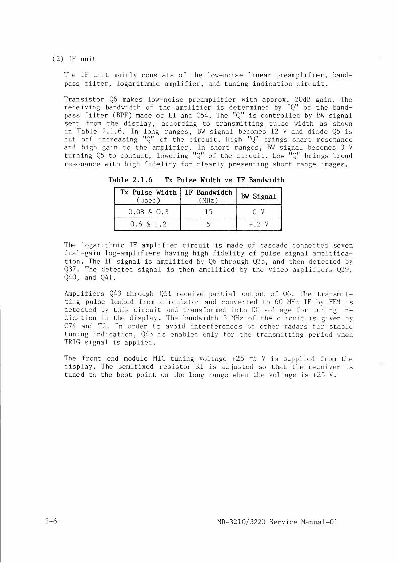
T r a n s i s t o r Q 6 m a k e s l o w - n o i s e p r e a m p l i f i e r w i t h a p p r o x . 2 0 d B g a i n . T h erece iv ing bandwid th o f the ampl i f ie r i s de termined by r rQr r o f the band-p a s s f i l t e r ( B P F ) m a d e o f L l a n d C 5 4 . T h e r f Q r f i s c o n t r o l l e d b y B W s i g n a ls e n t f r o m t h e d l s p l a y , a c c o r d i n g t o t r a n s m i t t i n g p u l s e w i d t h a s s h o w ni n T a b l e 2 . 1 , 6 . I n l o n g r a n g e s , B W s i g n a l b e c o m e s 1 2 V a n d d i o d e Q 5 i sc u t o f f i n c r e a s l n g f r Q r r o f t h e c i r c u l t . H i g h t r Q f r b r i n g s s h a r p r e s o n a n c ea n d h i g h g a i n t o t h e a m p l i f i e r . I n s h o r t r a n g e s , B W s i g n a l b e c o m e s 0 Vt u r n i n g Q 5 t o c o n d u c t , l o w e r i n g f r Q f r o f t h e c i r c u i t . L o w f f Q r r b r i n g s b r o a dr e s o n a n c e w i t h h i g h f i d e l i t y f o r c l e a r l y p r e s e n t i n g s h o r t r a n g e i m a g e s .
Table 2.L.6 Tx Pulse Width vs IF Bandwidth
Tx Pulse l{idth( u s e c )
IF Bandwidth(MHz )
BW Signal
0 . 0 8 & 0 . 3 1 5 O V
0 . 6 & r . 2 5 + L 2 V
The logar l thmic IF ampl i f ie r c i rcu i t i s made o f cascade connected sevend u a l - g a i n l o g - a m p l i f i e r s h a v i n g h i g h f i d e l i t y o f p u l s e s i g n a l a n p l i f i c a -t i o n . T h e I F s i g n a l i s a m p l i f i e d b y Q 6 t h r o u g h Q 3 5 , a n d t h e n d e t e c t e d b yQ 3 7 . T h e d e t e c t e d s i g n a l i s t h e n a m p l i f i e d b y t h e v i d e o a m p l i f i e r s Q 3 9 ,Q 4 0 , a n d Q 4 1 .
A m p l i f i e r s Q 4 3 t h r o u g h Q 5 1 r e c e i v e p a r t i a l o u t p u t o f Q 6 . T h e t r a n s m i t -t ing pu lse leaked f rom c i rcu la to r and conver ted to 60 NIHz IF by FEM isd e l e c l e d b y t h i s c i r c u i t a n d t r a n s f o r m e d i n t o D C v o l t a g e f o r t u n i n g i n -d i c a t i o n i n t h e d i s p l a y . T h e b a n d w l d t h 5 W l z o f t h e c i r c u i t i s g i v e n b yC 7 4 a n d T 2 . I n o r d e r t o a v o i d i n t e r f e r e n c e s o f o t h e r r a d a r s f o r s t a b l et u n i n g i n d i c a t i - o n , Q 4 3 i s e n a b l e d o n l y f o r L h e L r a n s m i t t i n g p e r i o d w h e nT R I G s i g n a l i s a p p l i e d .
The f ront end module MIC tuning vol tage +25 t5 V is suppl ied f rom thed isp lay . The semi f i xed res is to r R l i s ad jus ted so tha t the rece ive r i stuned to the best polnt on the long range when the vol tage is +25 V.
2-6 MD-32 I0 / 3220 Serv ice Manua l -01

2.2 D isp lay un i t
T h e d i s p l a y u n i l c o n s i s t s o f t h e f o l l o w i n g p r i n t e d c i r c u i t b o a r d s a n d a s -s e m b l l e s .
( 1 ) P o w e r s u p p l y( 2 ) L i n e f i l t e r s( 3 ) L o g i c u p p e r(4 ) Log ic lower(5 ) Con t ro l pane l w i th
membrane sheet(6 ) CRT un i t
T h e c o n t r o l c i r c u i t ( I C 3 )wave s igna l and con t ro lsthe ou tpu t vo l tage 1eve1 .POWER sw i tch , approx . i 0 Vcu i l . Accord ing to the CR
MD-32IO / 3220 Serv ice Manual-01
MD-32 LO / 3220-6000MD-3210-6100 & LF2i5NEWMD-32 10-7000MD-32 10-71 00MD-32 1 0-7200
KzOMM-O 1 B
f u n c t i o n s L o o s c i l l a t e s t h e s w l t c h i n g s q u a r et h e d u t y o f t h a t s i g n a l i n o r d e r L o r e g u l a t eWhen the power i s Lurned 0N by press ing thes t a r t i n g v o l l a g e i s g i v e n l o t h e c o n t r o l c i r -c o n s t a n t ( C B , R 2 0 , a n d V R l ) c o n n e c t e d t o t h e
T h e b l o c k d i a g r a m o f t h e d i s p l a y u n i t l s i l l u s t r a t e d i n F i g . 2 . 2
F romG y r o ' - " - )
I
r - - - - - " , - _ - i - - lII GYRO INTERFACEI
I KsA-08
i i'iiA-iit-7ooo'l
i ipl-qi-qp.go_:I
I i'i{ir:cis:a2oo-r
T o / f r o mANTENNAU N I T
F i g . 2 . 2Block Diagran ofDisplay Unit
12124132 VDC ( i lD-3210)24 VDC t10Z 0{D-3220)
2.2.I Power supply (l ' lD-321O/322O-6000)
M D - 3 2 1 0 i s o p e r a t e d b y t h e s h i p t s m a i n s o f 1 1 L o 1 8 , o r 2 I t o 3 6 V D C , w h i l eMD-3220 by 24 VDC I IOZ. The sh ip ' s ma in i s fed v ia l i ne f i l t e rs (MD-3210-6100 and LF-215) . The power supp ly MD-32 I0 /3220-6OOO is used fo r bo th t yperadars . The power supp ly conver l s the sh ip ' s ma ins to severa l k inds o f sup-p 1 y v o l t a g e s b y m e a n s o f a p u l s e c o n t r o l l e d s w i t c h i n g r e g u l a t o r . F i g . 2 . 2 . I(a ) shows the b lock d iag ra rn o f the power supp ly and l i ne f i l t e rs .
( f ) C o n t r o l c i r c u i t
') -7L - t

I C , t h e c i r c u i t o s c i l l a t e s a s w i t c h i n g s i g n a l l n a f r e q u e n c y o f 7 0 t l k H z .H a l f - c . y c l e s o f t h e s i g n a l a r e a l t e r n a t e l y a p p l i e d t o p u s h - p u 1 1 s w i t c h i n gc i r c u i t 1 a n d 2 r e s p e c t i v e l y . T h e w i d t h o f a p p l i e d s q u a r e w a v e i s c o n -t r o l l e d s o t h a t t h e o u t p u t v o l t a g e o f t h e c i r c u i t i s s t a b i l i z e d .
1 2 / ? 1 V!10t
POI"JERS w i t c h
Just af ter the power is turned 0N,t i va tes IC3 p reven t ing rush cu r ren tto protect the swi tch ing FETs, anda r e s h o w n i n F i g . 2 . 2 . 1 ( b ) .
+ 8 V
R e g u L a t e d+ 5 VR e g u L a t e d+ 1 2 V14agne t r onh e a t e r
R e g u L a t e d- 1 2 V
+ 1 0 0 V
+ 5 0 v
R e g u L a t e d+ 1 5 v
+300 v
F l o a t i n g2 4 V D C
t h e s o f t - s t a r L c i r c u i t g r a d u a l l y a c -and r ing ing o f the swi tch ing c i rcu i tr e c t i f l e r d i o d e s . T y p i c a l w a v e f o r m s
Fig. 2.2.I (a) Block Diagram of Power Supply and Line Fi l ters
0 s c i L L a t i o n I C 3 - 5
S o f t - s t a r t I C 3 - 4
S w i t c h i n g - 1 I C 3 - 8
S w i t c h ' i n g - 2 I C 3 - 1 1
E r r o r d e t e c t I C 3 - 1
Fig. 2.2.L (b) Waveforms of Contro l Ci rcu i t
When the so f t - s ta r t pe r iod comp le tes and the DC vo l tages become s tab le ,a par t o f the +100 V ou tpu t i s fed to the e r ro r vo l tage de tec to r (Q i9 ,20 , D36) . VR3 [V ADJ] se ts the re fe rence po in t o f the vo l tage regu la to rc i r cu l t . The e r ro r vo l tage i s fed back by pho to -coup le r Q2B to the con-
L ' i n e F i L t e r s
tY lD -3210 -6100&
L F - 2 1 5
S w i t c h i n gC i r c u i t 1
Q 1 , 2 , 1 1 , 1 2
S w i t c h i n gC i r c u i t ?
Q 3 , 4 , 1 3 , 1 1+1 00v
R e c t ' i f i e rD 4 t o 7O v e r V o L t .
Q 9 , 1 0
C o n t r o LC i r c u ' i t
r c 3
E r r o rV o L t a g eD e t e c t o rQ19 ,20,28Powe r 0N
a 5 t o 8
+300 VR e c t i f i e rD 1 2 t o 1 9
T xS w i t c hQ 2 3 t o? 6 , 2 9
P o w e r 0 F FQ 1 6 , 1 7
S o f t S t a r tc 1 1 P < ' 1 < 7
? 4 UR e c t i f i e r
D 3
R e g . + / - 1 ? V &C o n s t . C u r r e n t
R e c t i f i e rD 1 , 3 3 , 3 4 , r c l , 5 r 4
2-8 MD-32 I0/ 3'220 Service Manual-Ol

t ro l c i rcu i t IC3 to au tomat ica l l y ad jus t the du ty o f sw i tch ing waveformso tha t the er ro r vo l taee is min imized.
I f t h e s h i p ' s m a i n s u p p l y i s h i g h e r t h a n 4 2 V , o v e r - v o l t a g e d e t e c t o r - l( Q 9 , 1 0 ) d o e s n ' t a l 1 o w I C 3 t o s t a r t s w i t c h i n g o s c i l l a t i o n . O v e r - v o l t a g edetec tor -2 (Q30) mon i to rs the ou tpu t vo l tage o f the motor power 24 Vr e c t i f i e r d i o d e D 3 . T h e v o l t a g e i s a d j u s t e d b y V R 2 [ V L M T ] a n d f e d t o
Q 3 0 v i a z e n e r d i o d e D 2 B . I f t h e s h i p ' s m a i n s u p p l y o r o s c i l l a t i n g o u t p u t1 e v e 1 b e c o m e e x c e s s i v e l y h i g h , Q 3 0 c o n d u c t s t o s t o p o p e r a t i o n o f I C 3 .F u 1 1 y c l o c k w i s e p o s i t i o n o f V R 2 c o r r e s p o n d s t h e s h i p ' s m a i n o f 4 L V .
When P0WER swi tch is p ressed fo r more than 3 seconds, C13 is charged upf i r s t ^ . ' d t h e n C L 4 l s c h a r g e d u p t h r o u g h Q 1 6 a n d D 2 5 . Q 1 7 a n d Q 1 5 t h e nc o n d u c t c o n s e q u e n t l y t o s t o p I C 3 s w i t c h i n g o p e r a t i o n .
( 2 ) R e c t i f i e r c i r c u i t s
S t e p p e d u p / d o w n s w i t c h i n g w a v e v o l t a g e s d e r i v e d f r o m s e c o n d a r y w i n d i n g so f t r a n s f o r m e r T 1 a r e r e c t i f i e d a n d s m o o t h e d b y f u 1 1 - w a v e o r b r i d g e - t y p er e c t i f i e r s i n t o v a r i o u s D C s u p p l y v o l t a g e s . + I 2 V , - I 2 V , a n d + 5 V a r ef u r L h e r r e g u l a L e d b y r e s p e c L i v e L h r e e L e r m i n a L v o l L a g e r e g u l a L o r s .
T h e m a g n e t r o n h e a t e r v o l l a g e i s s u p p l i e d f r o m I C 5 t h r o u g h R 4 5 , 4 6 , 8 2 ,a n d V R 4 . T h e c i r c u i t d e l i v e r s 0 . 5 5 A c o n s t a n t c u r r e n l i n s h o r t r a n g e a n d0 . 4 4 A i n l o n g r a n g e o p e r a L i o n L o t h e m a g n e t r o n h e a t e r . T h e o u t p u t v o l t -a g e a t T P 5 i s a p p r o x . 7 V f o r o b t a i n i n g 6 , 3 V a t m a g n e t r o n h e a t e r . V R 4a d j u s l s t h e c u r r e n l L o 0 . 5 5 A c o n s t a n t i n s h o r t r a n g e o p e r a t i o n . I n l o n gr a n g e , t h e l o g i c b o a r d C P U d e l i v e r s ' h i g h '
I H . C . : h e a t e r c o n t r o l ] s i g -n a 1 , w h i c h a c t u a t e s p h o t o - c o u p l e r Q 3 2 t o s h u n t V R 4 . A s a r e s u l t , t h ec i r c u i t b e c o m e s t o d e l i v e r O . 4 4 A c o n s t a n t c u r r e n t t o t h e n a g n e t r o n .
2 . 2 . 2 L o g i c s e c t i o n
T h e l o g i c s e c t i o n i s c o m p o s e d o f t h e l o g i c u p p e r a n d l o g i c l o w e r b o a r d s .T h e l o g i c u p p e r b o a r d b a s i c a l l y f u n c t i o n s w i t h a C P U t o d i g i t a l l y c o n t r o lt h e s y s L e m . T h e l o g i c l o w e r b o a r d m a i n l y f u n c t i o n s t o p r o c e s s t h e r a d a rv i d e o s i g n a l , o s w e l l a s t o p r o d u c e t r i g g e r p u 1 s e .
( 1 ) L o g i c u p p e r ( M D - 3 2 1 0 - 7 0 0 0 )
T h e l o g i c u p p e r b o a r d c o n s i s t s o f t h e f o l l o w i n g c i r c u i t s :
C P U a n d p e r i p h e r a l c i r c u i tA d v a n c e d C R T c o n t r o l l e r ( A C R T C )
ACRTC cont ro l c i rcu i tCharac ter v ideo memoryC h a r a c t e r o u t p u t c i r c u i tD I P s w i t c h r e a d i n g c i r c u i tO t h e r s
(a ) CPU and per iphera l c i r cu i t
A 16-b i t m ic . rop rocessor UPD7020B (V40) i s used as8-k RAI ' I . The CPU t ransfers B-b i t da la through Lhecon ta ins A0 th rough A19 . A0 to A7 a re la tched a tA 1 9 a t I C 2 H ( H C 3 7 3 ) , w h i l e A 8 t o A 1 5 a r e d i r e c t l y
MD-32L0/ 3220 Serv ice Manual-Ol
CPU with 64-k ROM andd a t a b u s . A d d r e s s b u sICZC (HC373 ) , A16 to
t rans fe r red f rom CPU.
2-9

CPU operates wi th 10 MHz c lock made f rom the 20 Wl,z osc i l la tor output .
When the power is turned ot r , the power-on-c lear (POC) IC4K holds RESETte rmina l ( p i . #7 I ) o f CPU in "1ow" fo r severa l m i l l l seconds a f te r thelog ic vo l tage has been s tab i l i zed . CPU is rese t ( c lea red) in th i s pe r iodun t i l t he leve1 becomes "h igh" . A t the same t ime , POC s igna l de l i ve redfrom POC terminal resets other d ig l ta l c i rcu i ts such as RAM and ACRTC.
CPU is p rov ided w i th bu i l t - i n se r ia l da ta con t ro l un i t (SCU) to accep ta se r ies inpu t da ta d i rec t l y f rom nav iga to rs v la RXD te rm ina l .
T h e b l o c k d i a g r a m o f C P U i s s h o w n i n F i e . 2 . 2 . 2 . I .
A d d r e s s B u s Dala Bus
D 0 -
D I PSwi tch+ 5 V
Ser i a l
T n t o r l r r r r tr r r u r . r r v l r v
A C R T CDat
{t
AZPI NT3I NT6
RAMEnab I e
o t h
F i g . 2 . 2 . 2
--t,I
POC
. l
ROM Enab le
t odev i ce
Block Diagram of CPU
The CPU accep ts fo l l ow ing inLer rup t s igna ls .
rNTPZ AZP sent f rom logic lower board (Reformed AZrP)INTP3 Transfer end s lgnal f rom KCD-24INTP6 Reques t f rom gy ro in te r face un iL
AZP and L rans fe r end s igna l con t ro l the t im ing o f da ta t rans fe r f rom LSIto radar memory . The az imuth pu lses a re genera ted in the an tenna d r i vemoto r . The s igna l i s app l ied to the PLL 6 - t ime f requency mu l t i p l i e r i nt h e S C O N b o a r d a s m e n t i o n e d i n p a r a . 2 . 1 . 3 ( 2 ) , a n d 1 , 0 8 0 A Z I P p u l s e sare senl to the d isp lay per one antenna revolut ion. AZIP is reformed inthe log ic lower board in to AZP and sent to CPU. Between AZP pulses, CPUgenerates f ina l t iming pulse AZI to t ransfer 6-sweep dala f rom LSI tothe v ideo memory . A to ta l o f 6 ,480 sweep da ta t rans fe r comp le tes onea n t e n n a r e v o l u t i o n , i . e . 3 6 0 ' r o t a t i o n . F i g . 2 . 2 . 2 . 2 s h o w s t h e d a t at rans fe r r ing t lm ing char t .
AZP
AZI
IIII}
Data Transferring Timing Chart
RESET
RXD
I NTP2I NTP3iNTP6 POC
Power-0n-C l e a r ( P O C ) ROl| Enable
r Data set t ing
transfer
2* ro
F i g . 2 . 2 . 2 . 2
MD-32 I0 / 3220 Serv ice Manua l -0 l

(b ) Advanc.ed CRT cont ro l le r (ACRTC) and charac ter v ideo memory
Under CPU cont ro l , ACRTC IC9C (HC63484) genera tes a l l images o ther thanr a d a r i m a g e s . T h o s e i m a g e s i n c l u d e 1 i n e s , r i n g s , s y m b o l s , m a r k s , & s w e l las a lpha-numer ica l charac ters such as range sca les , VRM/EBL va lues , andother da ta . The produced image da ta a re wr i t ten in to the charac le r v ideo
m e m o r i e s f r o m I C 5 A t o I C 1 2 A . I h e o p e r a t i n g c l o c k i s 2 C L K w h i c . h i s m a d eb y d i v i d i n g t h e r e a d i n g c l o c k D C K o f v i d e o R A M i n t o I / 8 . F i g . 2 . 2 . 2 . 3i l l u s t r a t e s t h e b l o c k d i a g r a m o f A C R T C , v i d e o R A M ( V R A M ) a n d t h e i r p e r i -o h e r a l d e v i c e s .
D 0 - D 7 A D O - A D 1 5 , Rad arD i s p l a yA d d r e s s
Charac Le rV i d e o0 u L p u L
a o , , {L
CRT unr t
nuOu, fLSI 1
\/D <_-
E. SYNC -
VCK ---DCKH1
Fig. 2.2.2.3 Block Diagran of ACRTC and Per ipheral Devices
E . S Y N C s y n c h r o n i z e s t h e p r e s e n t a t i o n o f r a d a r e c h o i m a g e a n d c h a r a c . t e rv i d e o . I t h a n d l e s t h e r a d a r L S I a s m a s t e r d e v i c e a n d A C R T C s l a v e ; h o w -e v e r , 3 s t h e h o r i z o n t a l s c a n n i n g l i n e n u m b e r 1 , 1 5 3 f o r 2 O - i n c h C R T e x -c e e d s t h e r a d a r L S I m a x i m u m s c a n n i n g l i n e n u m b e r I , 0 2 4 , t h e v e r t i c a l
s y n c a n d v e r l i c a l a d d r e s s o f A C R T C a r e u s e d f o r r a d a r p i c t u r e d i s p l a y ,i n s L e a d o f s u c h s i g n a l s o f r a d a r L S I . F i g . 2 . 2 . 2 . 4 i l l u s t r a t e s t h e t i m -i n g c h a r t o f A C R T C o p e r a t i o n , w h e r e A d e s i g n a t e s ' a d d r e s s t a n d D t d a t a t .
T C L K ( I C g C - 5 0 )
A S ( I C g C _ 5 3 )
A D O - A D 1 6 ( I C g C )( E X C E P T A D B )
A D B , A 1 7 - A D 1 9( I C 9 C )
H C Y C ( I C g C - 5 2 )
H R D ( I C g C - 5 5 )
DEAl i ( ICgC-54)t l l
I w r i t e c y c i e I R e a d c v c l e I
Fig . 2 .2 .2 .4 ACRTC Timing Chart
A s s h o w n i n F i g . 2 . 2 . 2 . 5 , t h e c h a r a c t e r v i d e o m e m o r y c o n s i s t s o f f o u rm e m o r y g r o u p s . T h o s e g r o u p s i n c l u d e t h e m e m o r i e s f o r m a r k e r s , p l o t t i n g
i m a g e s , a n d a l p h a - n u m e r i c a l l e t t e r s , p l u s o n e g r o u p n a m e d t m a s k ' w h i c hd e t e r m i n e s t h e p r e s e n t a t i o n a r e a o f t h e r a d a r i m a g e p i c t u r e . C o n t e n t so f the v ideo RAM is admin ls t ra ted by ACRTC which wr i tes and reads thedata in accordance w i th the command or da ta sent f rom CPU.
READY- f-$yfi]L l In te r faceF-
I r c g H , 3 F I
A C R T C. I
f q C
DTACKV R A H
I C s A , 6 A ,] A , 8 A ,9 A , 1 0 A ,
A d d r e s sL a t c h
I C 8 C , 8 DP a r a . - t o -S e r i a l
Conve r l e rI C 3 A , 4 A ,r 3 A , 1 3 8
MD-32I0/ 3220 Serv ice Manual-O1 2-r1

2 ,048 (512 x a ) b i t s - - l
b i t s
b i t s
Fig. 2.2.2.5 Composi t ion of Character Video Memory
One ch lp o f the v ideo RAM (TC5242562) i s a dev ice ca11ed 'dua1 por t RAM'c o m m o n l y u s e d f o r m e m o r y o f i m a g e s . I n a d d i t i o n t o o r d i n a r y I I O p o r t , i th a s s e r i e s d a t a o u t p u t p o r t t o d e l i v e r t h e d a t a i n s e r i e s . T h e m e m o r ycons is ts o f RAM and SAM (ser ies access memory) por t ions , each o f themi s f u r t h e r d i v i d e d i n t o f o u r b l o c k s . O n e b l o c k c o m p r i s e s 5 I 2 x 5 L 2 b i t sRAI ' I and 5L2 b i ts SAM. When read ing the conten ts o f RAM, 2 ,048 b i ts memo-r i e s f o r o n e C R T s w e e p l i n e ( 5 I 2 i n f o u r b l o c k s ) a r e t r a n s f e r r e d t o r e -s p e c t i v e S A M i n p a r a 1 1 e 1 a s s h o w n i n F i g . 2 . 2 . 2 . 6 . T h e d a t a i n S A M c a nb e r e a d o u t i n s e r i e s , l i k e a s h i f t r e g i s t e r , b y t h e s e r i e s c l o c k S C .F o u r b i t s p a r a 1 1 e 1 o u t p u t o f S A M i s t h e n f e d t o a p a r a l 1 e l / s e r i e s c o n -v e r t e r ( F 9 1 5 ) t o f i n a l l y d e l i v e r t h e d a t a i n s e r i e s . O n c e t h e d a t a i st r a n s f e r r e d f r o m R A M t o S A M , b o t h m e m o r y p o r t i o n s b e c o m e i n d e p e n d e n t .T h a t m e a n s , d u r i n g r e l a t i v e l y l o n g p e r i o d w h e n t h e d a t a i s b e i n g r e a df r o m S A M , R A M c a n b e f r e e l y r e a d o r w r i t t e n b y C P U c o n t r o l .
Random Access Pu i t
RADi CAI]512x512512x572
RASCASc n
-[,,,
I,,
sr04 ISI03 | Ser ia lS I02 | Por tsr01 JSC
F i g . 2 . 2 . 2 . 6
( . ) D IP sw l tches
Three DIP sw i tches , SW1,board in order to presetI . 5 . 2 f o r d e t a i l s o f t h ethree swi tches is read by
(d ) Pane l i n te r face c i r cu i t
S1, i l2 , and SW3 are prov lded on the log ic uppert h e f u n c t i o n o f t h e e q u i p m e n t . R e f e r t o p a r a .
f u n c t i o n s s e t b y L h e s e s w i t c h e s . T h e s t a t u s o fthe CPU v ia da ta bus , D0 th rough D7.
Block Diagram of Dual Port RAM
The pane l da ta s igna l (PDT) de l i vered in ser ies f rom the cont ro l pane li s c o n v e r t e d i n t o B - b i t p a r a 1 l e 1 d a t a i n t h e p a n e l l n t e r f a c e c i r c u i t .
3 i ' i4
2 - r2 MD-32I0/ 3220 Serv ice Manual-01

The panel c lock (PCK) andThe output pulse of VRM,counted and read by CPUt iming char t o f the panel
pane l s t robe s igna l (RCK) a re used fo r t im ing .EBL and t rack -ba11 encoders a re respec t i ve ly
t h r o u g h t h e d a t a b u s . F i g . 2 . 2 . 2 . 7 s h o w s t h ei n t e r f a c e c i r c u i t .
RCK ( ICsE- l2
PCK ( ICBE-11
PDT ( rCSE-14
Fig. 2 .2.2.7 T iming Chart o f Panel In ter face Circu i t
F i v e p i e c e s B - b i t s h i f r r e g l s r e r s w i r h l a r c h H C 5 9 5 ( I C B E , 5 H , 3 H , 6 H ,and 4H) a re p rov ided fo r pane l i n te r face c i r cu i t to rece ive the s igna lsf rom con t ro l pane l . The PDT s igna l t ra in i s sh i f ted ln to the reg is te rsc o n n e c t e d i n s e r i e s . E v e r y t i m e w h e n t h e 4 1 s t d a t a ( a l w a y s t l o w t n a m e ddammy da ta 0 ) i s en te red , a l l t he da ta b i t s a re la tched by the s t robepu lse PCK.
( 2 ) L o g i c l o w e r ( M D - 3 2 1 0 - 7 1 0 0 )
The log ic lower board MD-3210-7100 con ta ins ana log c i r cu i t s to p roducethe an tenna con t ro l s igna ls such as t r i gger , tune s igna l , pu lse w id thr e l a y c o n t r o l , a n d o t h e r s . I t a l s o h a s a n a l o g c i r c u i t s t o p r o c e s s r a d a rre tu rn echo v ideo s igna l en te red f rom the an tenna . App l i ca t ion spec i f i edIC (ASIC) LSI KD-24 i s moun ted in the c i r cu i t to d ig i ta l l y p rocess thee c h o s i g n a l s f o r s a m p l i r g , s c a n c o n v e r s i o n , i n t e r f e r e n c e r e j e c L i o n , e X -pans lon , and to wr i te Lhe radar v ideo da ta in to the v ideo memory underthe contro l o f CPU in the log ic upper board. The radar v ideo data in thev ideo memory i s then composed w i th the charac te r v ideo p roduced in thelog ic upper , and sen t to the CRT un i t to d i sp luy .
For understanding the ASIC LSI for radar Type KCD-24, refer to Appendix.
( a ) A n a l o g s i g n a l p r o c e s s i n g c i r c u i t ( C i r c u i t d i a g r a m 3 / 3 )
F i g . 2 . 2 . 2 . 8 i l l u s t r a t e s t h e b l o c k d l a g r a m o f a n a l o g s i g n a l p r o c e s s i n gc i r c u i t . T h e f r o n t e n d o f t h e c i r c u i t j - s d e s i g n e d t o a c c e p t v i d e o s i g -n a l s o f 2 V p - p m a x i m u m 1 e v e 1 . A s t h e r a w v i d e o s i g n a l s e n t f r o m t h ea n t e n n a u n i t i s a b o u t 3 . 5 V p - p , t h e l e v e 1 i s a p p r o p r i a t e l y a d j u s t e d t o2 V p - p b y t h e p o t e n t i o m e t e r V R l I V I D E O I N ] .
The FTC c i rcu i t suppresses the ra in o r snow echo images by a t tenuat ingt h e l o w f r e q u e n c y c o m p o n e n t o f t h e s l g n a l . T r a n s i s t o r Q 2 d e t e c t s r a p i d l yf a l l i n g e d g e o f t h e i n c o m i n g v i d e o s i g n a l . T h e F T C c o n t r o l v o l t a g e s e n tf rom the d isp lay 1s g iven to Q40 and var ies the cur ren t f low ing th roughd i o d e s D 2 a n d D l . I n o t h e r w o r d s , t h e o p e r a t i n g v o l t a g e 1 e v e 1 a t Q 4 b a s ei s d e t e r m i n e d b y d i o d e s a c c o r d i n g t o t h e F T C c o n t r o l , a n d f r o n t e d g e s o fe c h o s i g n a l s a r e s e l e c t i v e l y a m p l i f i e d b y t h e f o l l o w i n g c i r c u i t . T r a n -s i s t o r Q 3 s t o p s t h e c u r r e n t o f e c h o f r o n t t o f l o w t h r o u g h D 2 a n d D l .
The STC waveform is made f rom the t r igger pu lse fed to IC IL . T t re max imuma m p l i t u d e o f S T C w a v e f o r m i s a d j u s l e d b y V R 2 I S T C L E V ] , w h i l e t h e s t a r t -ing t ime by VR3 [ STC TIME] . The d ischarg ing curve o f STC waveform is de-t e r m i n e d b y t h e C R t i m e c o n s t a n t g i v e n b y C 1 0 t o C 1 3 , a n d R 2 2 t o R 2 5 .When the STC vo l tage is app l ied to Q7, the load res is tance o f Q5 is 1ow-
mM
MD-321O/3220 Serv ice Manual-01 2 - r 3

3 . 5 V p - pInax.
e r e d a n d t h e v i d e o g a i n i s d e c r e a s e d . A c c o r d i n g t o t h e r e c o v e r i n g v o l t -s B e , t h e g a i n o f d i s t a n t e c h o e s i s r e c o v e r e d . S T C k n o b o f t h e c o n t r o lp a n e l v a r i e s t h e 1 e v e 1 o f S T C c u r v e t o a d j u s t t h e e f f e c t i v e a r e a o f S T C .
Radar LSIAntenna
DVz ')DV6 iDV7 )
Video -rVR1 tr
1fr
ConlroiPanel FTC
STCG A I N
STC level VR2STC time VR3
Tri.gger Threshold VR4
FiB. 2.2.2.8 Block Diagram of Analog Signal Processing Circui t
T h e v o l t a g e g i v e n f r o m G A I N c o n t r o l v a r i e s t h e o p e r a t i o n a l r e s i s t a n c eo f Q 1 6 L o a d j u s t t h e a m p l i t u d e g a i n . T h e b a n d w i d t h o f l o w - p a s s f i l t e ri s var ied by L l and var icap d iode D9 w i th the cont ro l s igna ls PWO andP\ ,^ /1 de l l vered f rom CPU accord ing to RANGE.
The EXP c i rcu i t enhances the s ize o f ta rge t images by ho ld ing the peakv a l u e t o t h e l e n g t h d e t e r m i n e d b y t h e C R c o n s t a n t o f C 2 6 , C 2 9 a n d R 5 4to R60. The CR cons tan t i s sw i tched over so Lhat image enhancement s taysu n c h a n g e d o n t h e s c r e e n e v e n R A N G E i s v a r i e d . C o n t r o l s i g n a l s E X P , E X P O ,E X P 1 , a n d E X P 2 a r e d e l i v e r e d f r o m C P U .
T h e a m p l i f l e d a n a l o g s i g n a l i s f i n a l l y c o n v e r t e d i n t o 3 - d l g i t d i g i t a ls i g n a l s b y h i g h s p e e d c o m p a r a t o r s I C Z L , 3 L , a n d 4 L . T h e r e f e r e n c e 1 e v e 1o f c o m p a r a t o r i s g i v e n f r o m t h e t h r e s h o l d c i r c u i t . T h e t h r e s h o l d i s d e e pi n s h o r t r a n g e w h l 1 e s h a l l o w i n l o n g r a n g e , S o L h a t t h e n o i s e d e n s i t i yo n t h e s c r e e n b e c o m e s u n i f o r r n . T h e L h r e s h o l d l e v e 1 i s a d j u s t e d b y V R 4I T H R E S H O L D ] , 3 s w e l l a s c o n t r o l l e d b y s i g n a l s T H O , T H 1 , T H z , a n d T H 3s e n t f r o m C P U . T h e d i g i t a l z e d v i d e o s i g n a l s , D V 2 , D V 6 , a n d D V 7 a r esampled by 77 .673 Nf r fz h igh f requency sampl ing c i rcu l t composed o f IC6X,6 Y , a n d 6 2 . T h e o u t p u t o f t h e s e c i r c u i t s i s s e n t t o t h e s a m p l i n g c i r c u i tof the radar LSI KCD-24.
( b ) R a d a r L S I ( K C D - 2 4 , I C T T )
The app l i ca t ion spec i f i ed IC (ASIC) radar LS I KCD-24 ( IC7V) i s con t ro l -1ed by the CPU through data bus. The radar LSI conta ins major radar s1g-na1 p rocess ing c i r cu i t s as l i s ted be1ow.
S a m p l i n g c i r c u i t a n d s a m p l i n g c l o c k d i v i d e rH igh speed bu f fe r memor j -esI n t e r f e r e n c e r e j e c t i o n c i r c u i tPo la r to X-Y coord ina tes conver te rCRT dr ive cont ro lOthers
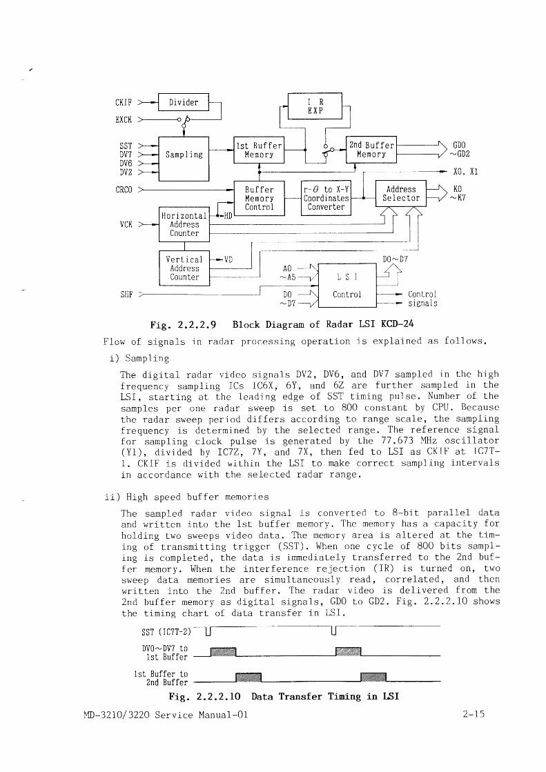
F i e . 2 . 2 . 2 . 9 i l l u s t r a t e s t h e b l o c k d i a g r a m o f r a d a r L S I K C D - 2 4 .
ControiQ 2 , 3 , 4 0
ControlQ 8 - 1 0 ,D 5 , I C l L
Conlro lQ 3 9 , D 1 0
2-r 4 MD-32L0 / 3220 Serv ice Manual-O1
D i v i d e r
Z n d B u f f e rl ' Iemo ryS a m p l i n g
1 s t B u f f e rM e m o r y
B u f f e rl ' |emo ryContro I
r- O lo X-YCoordinatesConverter
AddressS e l e c t o r
H o r i z o n t a lAddressCounter
V e r t i c a lAddressCounter
CKI F'
EXCK
SSTDV7u v oDV2
nDnn
VCK
DV0-DV? to1st Buffe
t"rl5tfiiirl: vzzz %z%AFig. 2.2 .z.LO Data Transf er Tining in ISI
I ' lD-32 LO / 3220 Service Manual-0l
Con Lro Is i g n a l s
Fig. 2.2.2.9 Block Diagram of Radar LSI KCD-24
F l o w o f s i g n a l s i n r a d a r p r o c e s s i n g o p e r a t i o n i s e x p l a i n e d a s f o 1 l o w s .
i ) S a m p l i n g
T h e d i q i t a l r a d a r v i d e o s i g n a l s D V z , D V 6 , a n d D V 7 s a m p l e d 1 n t h e h i g h
f requency sampl ing ICs IC6X, 6Y, and 6Z are fu r ther sampled in the
L S I , s t a r t i n g a t t h e l e a d i n g e d g e o f S S T t i m i n g p u l s e . N u r n b e r o f t h e
samples per one radar s \^ /eep is se t to 800 cons tan t by CPU. Because
t h e r a d a r s w e e p p e r i o d d i f f e r s a c c o r d i n g t o r a n g e s c a 1 e , t h e s a m p l i n g
f r e q u e n c y i s d e t e r m i n e d b y t h e s e l e c t e d r a n g e . T h e r e f e r e n c e s i g n a lf o r s a m p l i n g c l o c k p u l s e i s g e n e r a t e d b y t h e 7 7 . 6 7 3 M H z o s c i l l a t o r( Y 1 ) , d i v i d e d b y I C 7 Z , 7 Y , a n d 7 X , t h e n f e d t o L S I a s C K I F a t I C T T -
1 . C K I F i s d i v i d e d w i t h i n t h e L S I t o m a k e c o r r e c t s a m p l i n g i n t e r v a l s
in accordance w i th the se lec- ted radar range.
i i ) H i g h s p e e d b u f f e r m e m o r i e s
T h e s a m p l e d r a d a r v i d e o s i g n a l i s c o n v e r t e d t o 8 - b i t p a r a 1 l e 1 d a t a
a n d w r i t t e n i n t o t h e l s t b u f f e r m e m o r y . T h e m e m o r y h a s a c a p a c i t y f o r
ho ld ing two sweeps v ideo da ta . The memory area is a l te red a t the t i rn -
i n g o f t r a n s m i t t i n g t r i g g e r ( S S T ) . W h e n o n e c y c l e o f 8 0 0 b i t s s a m p l -
i n g i s c o m p l e t e d , t h e d a t a i s i m m e d i a t e l y t r a n s f e r r e d t o t h e Z n d b u f -
f e r m e m o r y . W h e n t h e i n t e r f e r e n c e r e j e c t i o n ( I R ) i s t u r n e d o t r , t w o
s \ { e e p d a t a m e m o r i e s a r e s i m u l t a n e o u s l y r e a d , c o r r e l a t e d , a n d t h e nwr i t ten in to the Znd bu f fe r . The radar v ideo is de l i vered f rom the2 n d b u f f e r m e m o r y a s d i g i t a l s i g n a l s , G D O t o G D z . F i g . 2 . 2 . 2 . I 0 s h o w s
the t im ins char t o f da ta t rans fer in LSI .
SST ( TC7T-2)
GDO-GD2
x0, x1
KO-K7
2 - r 5
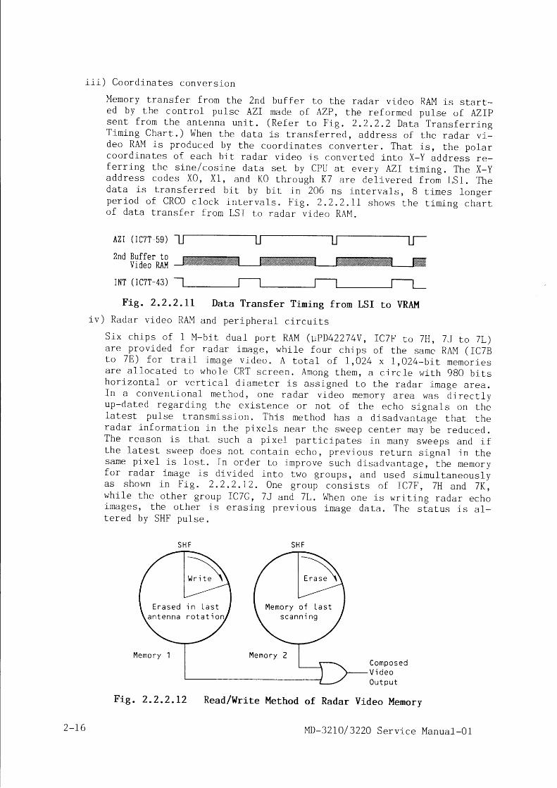
i i i ) C o o r d i n a t e s c o n v e r s i o n
Memory t rans fer f rom the 2nd bu f fe r Lo the radar v ideo RAM is s ta r t -ed by the cont ro l pu lse AZI made o f AZP, the re fo rmed pu lse o f AZI |s e n t f r o m t h e a n t e n n a u n i t . ( R e f e r t o F i g . 2 . 2 . 2 . 2 D a t a T r a n s f e r r i n gT i m i n g C h a r t . ) W h e n t h e d a t a i s L r a n s f e r r e d , a d d r e s s o f t h e r a d a r v i ld e o R A M i s p r o d u c e d b y t h e c o o r d i n a t e s c o n v e r t e r . T h a t i s , t h e p o l a rc o o r d i n a t e s o f e a c h b i t r a d a r v i d e o i s c o n v e r t e d i n t o X - Y a d d r e s s r e -fe r r ing the s ine /cos ine da ta se t by CPU a t every AZI t im ing . The X-ya d d r e s s c o d e s X 0 , X 1 , a n d K 0 t h r o u g h K 7 a r e d e l i v e r e d f r o m L S I . T h ed a t a i s t r a n s f e r r e d b i t b y b i t 1 n 2 0 6 n s i n t e r v a l s , B t l m e s l o n g e rp e r i o d o f C R C O c l o c k i n t e r v a l s . F i g . 2 . 2 . 2 . 1 I s h o w s t h e t i m i n g c h a r to f d a t a t r a n s f e r f r o m L S I L o r a d a r v i d e o R A M .
AZI (IC7T-59)
2nd Buffer tov ideos lsv%i77,v7v,%v, ,%v7.v777,777777V%i777,777V,%V%,
INT ( IC7T-43)
Fig . 2 .2 .2 .L r Data Trans fer T iming f rom LSr ro VRAM
i u ) R a d a r v i d e o R A M a n d p e r i p h e r a l c i r c u i t s
S i x c h i p s o f 1 M - b i t d u a l p o r t R A M ( 1 P D 4 2 2 7 4 V , I C T F r o 7 H , 7 J r o 7 L )a r e p r o v i d e d f o r r a d a r r m a g e , w h i l e f o u r c h i p s o f t h e s a m e R A M ( I C 7 Bt o 7 E ) f o r t r a i l i m a g e v i d e o . A t o t a l o f I , 0 2 4 x 1 , 0 2 4 - b i t m e m o r i e sa r e a l l o c a t e d t o w h o l e C R T s c r e e n . A r n o n g t h e m , a c i r c l e w i t h 9 B O b i t sh o r i z o n t a l o r v e r t i c a l d i a m e t e r i s a s s i g n e d t o t h e r a d a r i r n a g e a r e a .I n a c o n v e n t i o n a l m e t h o d , o n e r a d a r v i d e o m e m o r y a r e a w a s d i r e c t l yu p - d a t e d r e g a r d i n g t h e e x i s t e n c e o r n o t o f t h e e c h o s i g n a l s o n t h el a t e s t p u l s e t r a n s m i s s i o n . T h i s m e t h o d h a s a d i s a d v a n t a g e t h a t t h er a d a r i n f o r m a t i o n i n t h e p i x e l s n e a r t h e s w e e p c e n t e r m a y b e r e d u c e d .T h e r e a s o n i s t h a t s u c h a p i x e l p a r t i c i p a l e s i n m a n y s w e e p s a n d i ft h e l a t e s t s w e e p d o e s n o t c o n t a i n e c h o , p r e v i o u s r e t u r n s i g n a l i n t h es a m e p i x e l i s 1 o s t . I n o r d e r t o i m p r o v e s u c h d i s a d v a n t a g e , t h e m e m o r yf o r r a d a r i m a g e i s d i v i d e d i n t o t w o g r o u p s , a n d u s e d s i m u l t a n e o u s l ya s s h o w n i n F i g . 2 . 2 . 2 . I 2 . O n e g r o u p c o n s i s t s o f I C T F , 7 H a n d 7 K ' ,w h i l e t h e o t h e r g r o u p I C 7 G , 7 J a n d 7 L . W h e n o n e 1 s w r i t i n g r a d a r e c h oimages, the o ther i s e ras ing prev ious image da ta . The s ia tus is a1-t e r e d b y S H F p u 1 s e .
S H F S H F
C o m p o s e dV i d e o0 u t p u t
Read/Write Method of Radar Video Menory
E r a s e d i n L a s ta n t e n n a r o t a t i o
Wr i te
M e m o r y o f L a s ts c a n n i n g
Memo r y M e m o r y
2-16
F i g . 2 . 2 . 2 . 1 2
f ' lD-32I0/ 322A Service Manual-O I

Two radar memor ies a re read s imu l taneous ly and composed as shown int h e d r a w i n g . I n t h i s m e t h o d , w r i t i n g a n y p i x e l d o e s n o t a f f e c t p r e -v i o u s s t o r e d m e m o r y a n d l o s l n g t a r g e t n e a r s c o p e c e n t e r i s a v o i d e d .When the radar sweep or ig in does no t co inc ide w i th the d isp lay cent -o f , f o r e x a m p l e w h e n o f f - c e n t e r i n g i s t u r n e d o f l , C P U g e n e r a l l y c a l -cu la tes appropr ia te t rans fer r ing amount o f v ideo images f rom Znd bu f -f e r t o v i d e o R A M . T h i s m e t h o d , h o w e v e r , g i v e s h e a v y d u t y t o C P U e s p e -c i a 1 1 y i n ' t r u e m o t i o n t m o d e , E S i t s h o u l d c o n t i n u o u s l y c a r r y o u ts u c h c a l c u l a t i o n s . I n t h i s r a d a r , 8 0 0 - b i t m e m o r i e s p e r o n e s w e e p a r et r a n s f e r r e d e v e r y t i m e t o t h e v i d e o R A M , c o v e r i n g f u l 1 e x t e n t o fo f f -cen ter ing image. When read ing ou t the da ta f rom RAM on the o therh a n d , t h e p o r t i o n o f m e m o r i e s o u t s i d e L h e r a d a r s c o p e a r e a i s m a s k e db y t h e C R T v i d e o c o m p o s e r . F u r t h e r m o r e , i f L S I d e l i v e r e d a n y w r o n ga d d r e s s e x c e e d i n g t h e v i d e o R A M a r e a , I C B N , B P , 6 N , a n d 6 P f u n c t i o n st o c a n c e l t h e w r i t e e n a b l e p u l s e ( W E D K ) d e r i v e d f r o m L S I I C T T - 6 4 .
v ) C R T v i d e o c o m p o s e r
F i g . 2 . 2 . 2 , I 3 s h o w s t h e b l o c k d i a g r a m o f C R T v i d e o c o m p o s e r . T h e c l r -c u i t m i x e s t h e r a d a r v i d e o a n d c h a r a c t e r v i d e o b y s y n c h r o n l z i n g t h e mw i t h t h e d o t c l o c k o c c u r i n g i n t h e s a m e t i m i n g o f C R C O . T h e r a d a r v i -d e o i r n a g e s o u L s i d e t h e e f f e c t i v e r a d a r s c o p e o f 9 6 0 - d o t d i a . c i r c l ea r e r e j e c t e d b y M A S K d a t a f e d f r o m A C R T C o f t h e l o g i c u p p e r b o a r d ,MD-3210-7000.
Radar v ideo
Character v ideo
DoL c lock (DCK)
F i g . 2 . 2 . 2 . L 3B r i l l i a n c e c o n t r o l
CRT Video Composer
When jumper JP3 IMARKER] i " se t to IEXOR] , par t o f i rnages super impos-ed w l th markers such as r lngs , EBL, and VRM becomes dark . When JP3 iss e t t o I N 0 R M ] , s u c h p a r t b e c o m e s m o r e b r i g h t . I C 4 A A a l s o a c t u a t e d b yt h e d o t c l o c k s y n c h r o n i z e s a l l t h e g a t e o u t p u t . B r i l l i a n c e o f r a d a rv i d e o i m a g e s , r n a r k e r s , t r a i l i m a g e s , a n d a l p h a - n u m e r a l l e t t e r s a r ei n d e p e n d e n t l y a d j u s t e d b y r e s p e c L i v e c o n t r o l s o n t h e c o n t r o l p a n e 1 .S i g n a l s a r e c o m b i n e d w i t h r e s p e c t i v e d a t a a L t h e d i g j - L a 1 - t o - a n a l o gc o n v e r t e r . T h e a n a l o g v o l t a g e o u L p u t o f t h e c o n v e r t e r i s a m p l i f i e di n t h e c u r r e n t a m p l i f i e r s Q 2 7 t h r o u g h Q 3 4 . C o l l e c t o r s o f t h e s e t r a n -s i s t o r s a r e c o n n e c t e d i n p a r a l l e l c o m p o s i n g a w i r e d 0 R c i r c u i t , t h u sthe h ighes t 1eve1 s igna l i s sen l to CRT fo r image presenta t ion .
i v ) T U N E c i r c u i t
U n d e r C P U c o n t r o l , t h e l o g i c l o w e r b o a r d p r o v i d e s a u t o m a t i c t u n i n gfunc t ion to supp ly the op t imum MIC tun ing vo l tage to the an tenna. Inmanua l tun ing mode, a tun ing vo l tage is manua l ly de l i vered f rom VR4
ITUNE] o f the cont ro l pane1. i {hen ITUNE] knob is tu rned to AUTO, CPUautomat ica l l y ad jus ts the tun ing vo l tage to the po in t where thetun ing meter shows max imum. In o rder to make co inc idence o f the re -ce iver op t imum tun ing po in t and tun ing meter max imum po in t , VR5 ITUNEA U T O ] i " c a r e f u l l y a d j u s t e d . I f t h e t u n i n g m e t e r r e a c h e s f u 1 1 s c a l eo r e x c e e d s t h e s c a 1 e , A U T O T U N E d o e s n o t f u n c t i o n p r o p e r l y . I n s u c , ha case, ad jus t VR7 ITUNE MET] so tha t the tun ing meter max imum po in t
CRT V ideo0uIput
D ie i ta l -to -Ana logConverterQ27 -34
MD-32 IO / 3220 Serv ice Manua l -O1 2 - r7
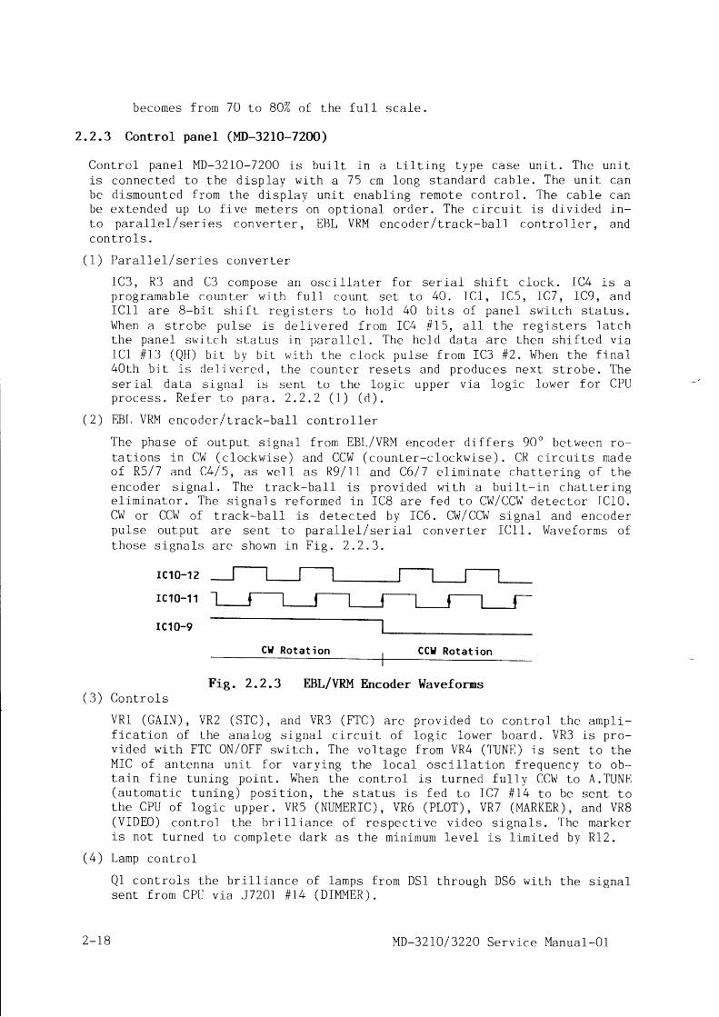
becomes f rom 70 Lo BOZ o f Lhe fu11 sca1e .
2 .2 .3 Control panel (l ' lD-321O-72OO)
C o n t r o l p a n e l M D - 3 2 1 0 - 7 2 0 0 i s b u i l t i n a t i l t i n g t y p e c a s e u n i t . T h e u n i ti s c o n n e c t e d t o t h e d i s p l a y w i t h a 7 5 c m l o n g s t a n d a r d c a b 1 e . T h e u n i t c a nb e d i s m o u n t e d f r o m L h e d i s p l a y u n i t e n a b l i n g r e m o t e c o n t r o l . T h e c a b l e c a nb e e x t e n d e d u p t o f i v e m e t e r s o n o p t i o n a l o r d e r . T h e c i r c u j - t i s d i v i d e d i n -t o p a r a 1 1 e l / s e r i e s c o n v e r t e r , E B L V R M e n c o d e r l t r a c . k - b a l 1 c o n t r o l l e r , a n dc o n t r o 1 s .
( 1 ) P a r a l T e L / s e r i e s c o n v e r t e r
I C 3 , R 3 a n d C 3 c o m p o s e a n o s c i l l a t e r f o r s e r i a l s h i f t c l o c k . I C 4 i s ap r o g r a m a b l e c o u n t e r w i t h f u 1 1 c o u n t s e t t o 4 0 . f C l , I C 5 , I C 7 , I C 9 , a n dI C l 1 a r e B - b i t s h i f t r e g i s L e r s t o h o l d 4 0 b i t s o f p a n e l s w i t c h s t a t u s .W h e n a s t r o b e p u l s e i s d e l i v e r e d f r o m I C 4 # 1 5 , a l l t h e r e g i s t e r s l a t c ht h e p a n e l s w i t c h s l a t u s i n p a r a l 1 e l . T h e h e l d d a t a a r e t h e n s h i f t e d v i aI C 1 # 1 3 ( Q H ) b i t b y b i t w i t h L h e c l o c k p u l s e f r o m I C 3 # 2 . W h e n t h e f i n a l4 0 t h b i t i s d e l i v e r e d , L h e c o u n t e r r e s e l s a n d p r o d u c e s n e x t s t r o b e . T h eser ia l da ta s igna l i s sen t to Lhe log ic upper v la log ic lower fo r CPUp r o c e s s . R e f e r L o p a r a . 2 . 2 . 2 ( 1 ) ( d ) .
( 2 ) E B L V R M e n c o d e r / L r a c k - b a 1 1 c o n t r o l l e r
T h e p h a s e o f o u t p u t s i g n a l f r o m E B L / V R M e n c o d e r d i f f e r s 9 0 o b e t w e e n r o -t a t i o n s i n C W ( c l o c k w i s e ) a n d C C W ( c o u n t e r - c l o c k w i s e ) . C R c . i r c u i t s m a d eo f R 5 / 7 a n d C 4 / 5 , 3 s w e l l a s R 9 / 1 1 a n d C 6 l 7 e l i m i n a t e c h a t l e r i n g o f t h ee n c o d e r s i g n a l . T h e t r a c k - b a 1 1 i s p r o v i d e d w l t h a b u i l l - i n c h a t t e r i n ge l i m i n a t o r . T h e s i g n a l s r e f o r m e d i n I C B a r e f e d t o C W / C C W d e t e c t o r I C 1 0 .CI , { o r CC\ , { o f t rack-ba11 is de tec ted by IC6. CW/CCW s igna l and encoderp u l s e o u t p u t a r e s e n L t o p a r a l l e l / s e r i a l c o n v e r t e r I C 1 1 . W a v e f o r m s o ft h o s e s i g n a l s a r e s h o w n i n F i g . 2 . 2 . 3 .
rc1 0-1 2
rc10-11 -
rc10-9
Ctl Rotat ion CCtl Rotat i on
Fig. 2.2.3 EBL/VRM Encoder Waveforms( 3 ) C o n t r o l s
V R l ( G A I N ) , V R 2 ( S T C ) , a n d V R 3 ( F T C ) a r e p r o v i d e d t o c o n t r o l t h ef i ca t ion o f the ana log s igna l c i r cu i t o f l og ic lower board . VR3vided wi th FTC 0N/0FF swi tch. The vol tage f rorn VR4 (TUNE) is sentMIC o f an tenna un i t fo r va ry ing the 1oca1 osc i l l a t i on f requencyta in f ine tunlng point . When the contro l is turned fu1ly CC\I I to(au tomat i c tun ing ) pos i t i on , the s ta tus i s fed to IC7 # I4 to bethe CPU o f l og ic upper . VR5 (NUMERIC) , VR6 (PLOT) , VR7 (MARKER) ,(V IDE0) con t ro l the b r i l l i ance o f respec t l ve v ideo s igna ls . Theis not turned to complete dark as the min imum 1eve1 is l imi ted by
(4 ) La rnp con t ro l
Qi contro ls the br i l l iance of lamps f rom DSl through DS6 wi th thesen t f rom CPU v ia J720 I # I4 (D IMMER) .
ampl i -i s p r o -
to theto ob-A . TUNE
sent toand VR8
markerR l 2 .
s ignal
2 _ I B MD-32 I0 / 3220 Serv ice Manual-O1
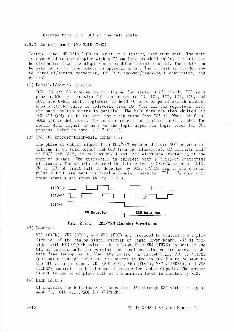
becomes f rom 70 to BO% of Lhe fu l l sca1e.
2.2.3 Control panel ( I '1D-321O-72OO)
C o n t r o l p a n e l M D - 3 2 1 0 - 7 2 0 0 i s b u i l t i n a t i l t i n g t y p e c a s e u n i t . T h e u n i ti s c o n n e c t e d t o t h e d i s p l a y w l t h a 7 5 c m l o n g s t a n d a r d c a b 1 e . T h e u n i t c a nb e d i s m o u n t e d f r o m L h e d i s p l a y u n i t e n a b l i n g r e m o t e c o n t r o l . T h e c a b l e c a nb e e x t e n d e d u p t o f i v e m e t e r s o n o p t i o n a l o r d e r . T h e c i r c u i t i s d i v i d e d l n -t o p a r a 1 1 e 1 / s e r i e s c o n v e r t e r , E B L V R M e n c o d e r / t r a c k - b a l 1 c o n l r o l l e r , a n dc o n t r o l s .
( 1 ) P a r a 1 1 e l / s e r i e s c o n v e r t e r
I C 3 , R 3 a n d C 3 c o m p o s e a n o s c i l l a t e r f o r s e r l a l s h i f t c 1 o c k . I C 4 i s ap r o g r a m a b l e c o u n t e r w i l h f u l 1 c o u n t s e L t o 4 0 . I C l , I C 5 , I C 7 , I C 9 , a n dI C l 1 a r e 8 - b i t s h i f t r e g i s l e r s t o h o l d 4 0 b i t s o f p a n e l s w i t c h s t a t u s .W h e n a s t r o b e p u l s e i s d e l i v e r e d f r o m I C 4 # 1 5 , a l l t h e r e g i s L e r s l a t c ht h e p a n e l s w i t c h s t a t u s l n p a r a 1 1 e l . T h e h e l d d a t a a r e t h e n s h i f t e d v l aI C l # I 3 ( Q H ) b i t b y b i t w i t h t h e c l o c k p u l s e f r o m I C 3 # 2 . W h e n t h e f i n a l4 0 t h b i t i s d e l i v e r e d , t h e c o u n l e r r e s e t s a n d p r o d u c e s n e x t s t r o b e . T h eser ia l da ta s igna l i s sen t to L i re log ic upper v ia log ic lower fo r CPUp r o c . e s s . R e f e r t o p a r a . 2 . 2 . 2 ( 1 ) ( d ) .
( 2 ) E B L V R M e n c o d e r / L r a c k - b a 1 1 c o n t r o l l e r
T h e p h a s e o f o u L p u t s i g n a l f r o m E B L / V R M e n c o d e r d i f f e r s 9 0 o b e t w e e n r o -t a t i o n s i n C W ( c l o c k w i s e ) a n d C C W ( c o u n t e r - c l o c k w i s e ) . C R c i r c u i t s m a d eo f R 5 / 7 a n d C 4 / 5 , 3 s w e l l a s R 9 / 1 1 a n d C 6 / 7 e l i m i n a t e c h a t l e r l n g o f t h ee n c o d e r s i g n a l . T h e t r a c k - b a l 1 i s p r o v i d e d w i t h a b u i l l - i n c h a t t e r i n ge l i m l n a t o r . T h e s i g n a l s r e f o r m e d i n I C B a r e f e d t o C W / C C W d e t e c t o r I C 1 0 .C W o r C C W o f L r a c k - b a 1 1 i s d e t e c t e d b y I C 6 . C W / C C W s i g n a l a n d e n c o d e rp u l s e o u t p u t a r e s e n t t o p a r a 1 1 e 1 / s e r i a l c o n v e r t e r I C 1 1 . W a v e f o r m s o ft h o s e s i g n a l s a r e s h o w n i n F i g . 2 . 2 . 3 .
rc10-1 2
r c10-11 -
rc10-9
Cl l Rotat ion CCI Ro ta t i on
Fig. 2.2.3 EBL/VRM Encoder Waveforms( 3 ) C o n t r o l s
V R 1 ( G A I N ) , V R 2 ( S T C ) , a n d V R 3 ( F T C ) a r e p r o v i d e d t o c o n t r o l t h ef i ca t ion o f the ana log s igna l c i r cu i t o f l og ic lower board . VR3vided wi th FTC 0N/0FF swiLch. The vol tage f rom VR4 (TUUE) is sentMIC o f an tenna un i l f o r va ry ing the 1oca l osc i l l a t i on f requencyta in f i ne tun lng po in t . When the con t ro l i s tu rned fu1 ly CCW Lo(au tomat i c tun ing ) pos i t i on , the s ta tus i s fed to IC7 # I4 to bethe CPU o f l og ic upper . VR5 (NUMERIC) , VR6 (PL0T) , VR7 (MARKER) ,(V IDEO) con t ro l the b r i l l i ance o f respec t i ve v ideo s igna ls . Theis not turned to complete dark as the min imum 1eve1 is l iml ted by
(4 ) Lamp con t ro l
Q1 con t ro ls the b r i l l i ance o f l amps f rom DSI th rough DS6 w l th thesent f rom CPU v ia J72OI #14 (DI I ' tv lER).
amp l i -i s p ro -
to theto ob-A . TUNE
sent toand VRB
markerR 1 2 .
s ignal
2 _ I B MD-32 I0 / 3220 Serv lce Manual-0 l

3 . ADJUST},IENT
C A U T I O N S
(1) H igh vo l tages a re app l ied to the an tenna and d isp lay un i t s .(2 ) Sh ip ' s ma ins supp ly i s app l ied to a ce r ta in in te rna l un i t even when the
power i s tu rned o f f .(3 ) Con f i rm tha t the ra ted fuses a re used accord ing to the sh ip rs ma ins .(4) Preheat magnetron in STANDBY more than 30 minutes, for the f i rs t t i rne
tu rn ing the power on a f te r i ns ta l l a t ion , o r magne t ron j - s rep laced .(5 ) Be fo re ad jus tment , a11ow the equ ipment abou t 30 m inu tes in the t rans -
mi t t i ng cond i t i on .
3. 1 Location of Controls
Ad jus t ing con t ro ls and sw i tches a re loca ted on log ic upper (MD-3210-7000)and log ic lower (MD-32I0-7 i00) boards mounted r ight hand ins ide the d isp layu n l t a s s h o w n i n F l g . 3 . 1 . B y r e m o v i n g f o u r t e e n ( 1 4 ) f i x i n g s c r e w s , t h ed isp lay cover can be removed to access these con t ro ls and sw i tches .
L o g i c u p p e r( N D - 3 2 1 0 - 7 0 0 0 )
L o g ' i c L o w e r(MD-321 0 -71 00 )
D I P s w i t c h
si.J2) w l
stJ3
V R 1 O( P . R . F . )
V R 1( V I D E O I N )
V R 3
VR2( L E V E L )
S t l 2 V R 4 ( T I M E )
V R 5 ( T H R E S H O L D )
V R 7 V R 6 ( A U T O )VR9 VR8 ( I ' IETER ) (MANUAL)( C O N T R A S T ) ( T X D E L A Y )
Fig. 3.1 Location of Controls and Switches
3.2 Adjustnent After Installation
I M P O R T A N T
Af te r ins ta l la t ion , do no t fa i l to rnake in i t ia l ad jus tment o f con t ro ls asm e n t i o n e d b e 1 o w .
3 . 2 . L T u n i n g
MD-32I0/3220 is prov ided wi th automat ic tun ing fac i l i ty . When TUNE contro lis turned fu l1y counter-c lockwise to AUTO posi t ion, the image gain shouldbe maximum as presented in manual tun ing mode set at the maximum point byTUNE con t ro l . I f AUTO tun ing op t imum po in t i s abnorma l , ca r ry ou t fo l l ow ingad jus tment in o rder .
MD-32I0/3220 Serv ice Manual-O1 3-1

AU
1) Wi th RANGE k"y , se lec t 24 nm (1ong pu lse ) range .2) Set the pointer of TIINE control on the control panel at
the cen te r pos i t i on as shown 1e f t .3) S1ow1y turn VR6 (MANUAL) of MD-3210-7100 to the point
where ta rge ts a re mos t s t rong ly v i s ib le on the sc reen .(+25 t1V a t p in #3 o f the rea r pane l connec to r J6005)
4) Adjust VR5 (AmO) so that the tuning meter shows maximumind ica t ion . (+5 t0 .5V a t p in #9 o f the rea r pane l con-nec to r J6006)
5) I f the tuning meter l ights up a l l the way and the rnaxi -mum point cannot be d iscr iminated, sd just VR7 ( l " lETER) sothat the maximum indicaLion becomes about 807" of fu11s c a l e , t h e n r e p e a t s t e p ( 4 ) .
(noise level )3 .2 .2 Prese t ga in
Th is ad jus tment i s requ i red to c lea r l y d i sp lay re la t i ve ly sma11 ta rge ts .
(1 ) Ro ta te GAIN con t ro l o f the con t ro l pane l fu11y c lockw ise .(2) Rotate STC, FIC and l l l i lE contro ls fu11y counter-c lockwise.(3) Wi th RANGE kuy, se lect the maximum range.(4) Turn IR.EXP and PI IOT of f wi th respect ive contro l keys.(5) Adjust VR4 (THRESH0LD) of MD-3210-7100 so that noise speckle becomes
j u s t v i s i b l e .
3 . 2 . 3 S T C
Rotate FI IC and TUNE contro ls fu11y counter-c lockwise.Turn IR.EXP and PLOT of f wi th respect ive contro l keys.With RANGE k"y, se lect L2 nm range.Ro ta te GAIN con t ro l o f the con t ro l pane l fu l l y c lockw ise .Rotate STC contro l so that noj -se speckles are suppressed up to 6 Df l ,and a few s t rong echoes rema in near cen te r o f the sc reen .
I f ad jus tment (5 ) above i s d i f f i cu l t caused by excess ive images , take fo1 -low ing s teps :
(5 ) Ro ta te STC con t ro l fu11y c lockw ise .(6) Adjust VR3 (THE) and VR2 (LEVEL) of log ic lower I '1D-3210-7100 as below.
(a) Set RANGE to 0.25 nm and adjust VR3 f rom c lockwise to counter-c1ock-w ise , so tha t the s ta r t i ng po in t o f STC becomes the cen te r o f sc reen .
(b) Set RANGE to 12 nm and adjust VR2 so that noise is suppressed up to6 nm on the sc reen .
T U N E^A
'/4 S-'- . / / \ z
(( \_
T O
3.2.4 Tr igger delay
I f the image of a s t ra ight target , such asbe low, i t rnay be caused by improper t r i ggero f an tenna cab le .
( 1 )( 2 )( 3 )( 4 )( s )
breakwater i s de formed as shownd e 1 a y , a c c o r d i n g t o t h e l e n g t h
N o r m a L E x c e s s i v e d e L a yS h o r t d e L a y
3-2 I 'D-32I0/ 3220 Serv ice Manual-O1

I n such a case , ad jus tment i s made as fo l l ows :
( 1 ) W i t h R A N G E k e y , s e l e c t 0 . 2 5 n m .(2) Adjust VR6 (TX DELAY) of MD-3210-7100 so that
becomes norma l as fo1 lows .( a ) T h e s t r a i g h t t a r g e t s a r e c o r r e c t l y p r e s e n t e d .(b ) A ta rge t w i th known d is tance 1s p resen ted a t
VRM f or range measurernent .
the image on the screen
c o r r e c t p o s i t i o n . U s e
3 .2 .5 SI{F and bearing
A f t e r i n s t a l l a t i o n a d j u s t m e n t s m e n t i o n e d a b o v e a r e c o m p l e t e d , c o n f i r m S H Fa n d a d j u s t b e a r i n g , i f n e c e s s a r y , a s f o 1 1 o w s .
( 1 ) W h e n t h e s h i p i s m o o r i n g o r c a l r n l y a n c h o r i n g , f i n d s o m e s t a t i o n a r y v i s -i b l e t a r g e t s i n a d i s t a n c e o f 4 t o B n m .
( 2 ) M e a s u r e t h e b e a r i n g o f t a r g e t s o n t h e c o m p a s s a s w e l l a s o n t h e r a d a rs c r e e n . I f t h e r a d a r b e a r i n g d e v i a t e s m o r e t h a n + 1 o f r o m t h e c o m p a s sb e a r i n g , c o r r e c t i o n c a n b e m a d e a s b e 1 o w .
( 3 ) B e a r i n g e r r o r w i t h i n + 1 1 " c a n b e c o r r e c t e d t o t l o b y r o t a r y s w i t c h e sS W 2 ( c o a r s e ) a n d S W l ( f i n e ) o f M D - 3 2 1 0 - 7 1 0 0 . I f e r r o r i s m o r e L h a n+ 1 1 o , f u r t h e r + 5 o a d j u s t a b l e r a n g e i s p r o v i d e d i n t h e a n t e n n a u n l t .
( 4 ) B e a r i n g a d j u s t r n e n t i n a n t e n n a u n i t i s m a d e a s f o l l o w s :f ) F i r s t o f a l l , n o t e t h a t i m a g e s a r e
L o b e r o t a L e d c l o c k w i s e ( C W ) o rcounter -c lockwise ( CCW) f o r cor -r e c t i n g e r r o r .
i f ) T u r n o f f t h e p o w e r .i i i ) O p e n t h e a n t e n n a r e a r c o v e r .
i r r ) F ind the SHF lead swi tch as showni n t h e r i g h t . L o o s e n f i x i n g s c r e w sa n d m o v e t h e b o a r d f u l 1 y l e f t w a r d sf o r CW i rnage ro ta t ion , o r r igh t -w a r d s f o r C C W r o t a t i o n .
v ) F i x t h e b o a r d w i t h f i x i n g s c r e w sa n d r e s t o r e t h e r e a r c . o v e r . T u r no n t h e p o w e r a n d t r a n s m i l .
v i ) R e a d j u s t S W Z a n d S W l o f M D - 3 2 1 0 -7 1 0 0 s o t h a t t h e b e a r i n g e r r o rbecomes less than +1 o on thes c o p e .
N o t e : b e a r i n g e r r o r e x c e e d s + 1 6 " , c h e c ka l i g n e d w i t h t h e b o w l i n e o r n o t .
3.3 Adjustment of Antenna Unit
N o a d j u s t i n g p o i n t e x i s t s 1 n t h ef o r i n i t i a l b e a r i n g a d j u s t m e n t b y
t h e d i r e c t i o n o f a n t e n n a u n i tI f- ; ^I b
a n t e n n a f o r o r d i n a r yS H F s w i l c h m e n t i o n e d
r n a i n t e n a n c e , e x c e p Li n p a r a . 3 . 2 . 5 ,
3.4 Adjustment of Display
3 .4 .l Power supply (l 'fD-321O / 3220-6000 )
T h e p o w e r s u p p l y b o a r d i s a d j u s t e d f o r t h e s w i t c h i n g r e g u l a t o r o s c . i l l a t i n gf r e q u e n c y , + 1 0 0 V o u t p u t 1 e v e 1 , a n d m a g n e t r o n h e a t e r v o l l a g e . A d j u s t m e n t
SIIF switch
MD-32 I0 / 3220 Serv ice Manua l -O l J _ J

i s m a d e a s f o l l o w i n g p r o c e d u r e . A c c e s s t o t h e b o a r d c a n b e m a d e b y d i s a s -s e m b l i n g t h e r e a r p a n e l o f t h e d l s p l a y . F i g . 3 . 4 . 1 i l l u s t r a t e s t h e l o c a t i o no f m e a s u r i n g / a d j u s L i n g p o l n t s o f p o w e r s u p p l y b o a r d .
( 1 ) O s c i l l a t i n g f r e q u e n c y
(a ) Wi th RANGE key , se lec t 24 nm range .(b ) Connec t a f requency coun te r be tween IC3 p in #9 [E1 ] and #7 [DC( - ) o f
i n p u t l i n e ] .( . ) Adjust VRI so Lhat the f requency becomes 35 tO.5 kLlz .
(2 ) 100 V ou tpu t vo l tage
(a ) Connec t a DC vo l tmete rTP3 and TP6 (GND) .
(b ) Ad jus t VR3 so tha t the
(3 ) Magne t ron hea te r cu r ren t
(a ) Connec t a DC vo l tmete r o r c i r cu i t tes te rT P 4 a n d T P 5 t ( - ) s i d e l .
(b ) Ad jus t VR4 so tha t the vo l tage becomes asM D - 3 2 1 0 : + 1 . 8 7 t 0 . 1 9 VM D - 3 2 2 0 : + I . 7 7 t 0 . 1 8 V
V R 4 T P 4
r c3
VR1
or c i r cu i t tes te r measurab le 150 V DC. be tween
vo l tage becomes +100 tO .1 V .
rneasurable 3 V DC, between
f o l l o w s :
TP6
V R 3 TP3
3 . 4 . r
R 5 4
Measuring/aaiusting Points of Power Supply
3-4
Fig.
I " lD-32I0 / 3220 Serv ice Manual-Ol

I
ti
3.4.2 Logic upper (MD-3210-7000)
As shown in F ig . 3 .1 , th ree D IP sw i tches , SWI th rough SW3 are mounted onthe log ic upper board (MD-3210-7000) in o rder to p rese t the opera t ion o fequ ipment . Func t ions se t by those sw i tches and the i r s tandard se t t i ngs a rel i s t e d i n p a r a . 1 . 5 . 2 .
3.4.3 Logic lower (1.{D-3210-710O)
Ad jus t ing con t ro ls and sw i tches o f l og ic lower board (MD-3210-7100) a re i1 -l u s t r a t e d i n F i g . 3 . 1 . M o s t o f t h e a d j u s t m e n t s s h o u l d b e c a r r i e d o u t j u s ta f t e r i n s t a l l a t i o n , w h i c h a r e e x p l a l n e d i n p a r a . 3 . 2 .
( i ) P u l s e r e p e t i t l o n f r e q u e n c y ( P R F )
The pu lse repe t i t i on f requency (PRF) ad jus tment i s made as fo11ows.
(a) Wi th the funct ion swi tch set at STANDBY, connect a f requency counterto TP3.
(b) Adjust VR10 (PRF) so that the f requency becomes 6,000 +50 Hz.
( 2 ) T u n i n g
R e f e r t o p a r a . 3 . 2 . I .
(3 ) V ideo inpu t 1eve l
In o rder to op t im ize the e f fec t o f STC, FTC and ga ln con t ro l , the inpu tleve l o f v ideo s igna l f rom the IF un i t i s ad jus ted as fo l l ows :
( " ) C o n n e c t a n o s c i l l o s c o p e t o T P 6 ( b a s e o f Q 2 ) .(b ) Synchorn j -ze the osc i l l oscope to the pos l t i ve phase radar t r i gger .( . ) Tu rn the radar to t ransmiss ion and observe the v ideo inpu t s igna l .
Adjust VRl so that the input s ignal 1evel becomes 2 Vp-p.
( 4 ) P r e s e t g a i n ( n o i s e l e v e l )
R e f e r t o p a r a . 3 . 2 . 2 .
(s) src
R e f e r t o p a r a . 3 . 2 . 3 .
( 6 ) T r i g g e r d e l a y
R e f e r t o p a r a . 3 . 2 . 4 .
(7 ) SHF and bear ing
R e f e r t o p a r a . 3 . 2 . 5 .
(B) Jumper p in se t t i ng
In o rder to se t opera t iona l cond i t i ons o f the un i t , f i ve ju rnper p insare prov ided on the log ic lower board (FfD-32I0-7 100) . Funct ions andi n i t i a l s e t t i n g s t a t u s o f t h o s e p i n s a r e e x p l a i n e d 1 n p a r a . 1 . 5 . 1 .
l'
MD-32I0 / 3220 Serv ice Manual-Ol 3-5
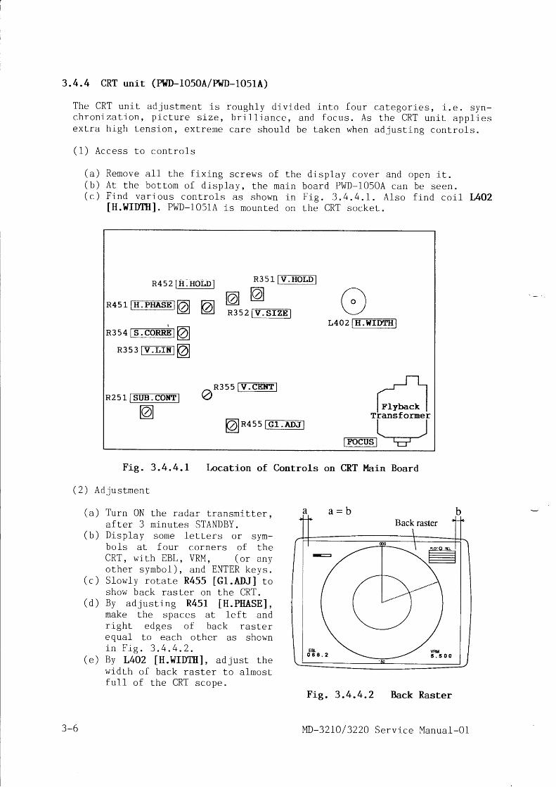
3.4.4 CRT unit (PWD-1050A/PI{D-1051A)
T h e C R T u n i t a d j u s t m e n t i s r o u g h l y d i v i d e d i n t o f o u r c a t e g o r i e s , i . e . s y n -c h r o n i z a t i o n , p i - c t u r e s i z e , b r i l l i a n c e , a n d f o c u s . A s t h e C R T u n i L a p p l i e se x t r a h i g h t e n s i o n , e x t r e r n e c a r e s h o u l d b e t a k e n w h e n a d j u s t i n g c o n t r o l s .
( 1 ) A c c e s s t o c o n t r o l s
( a ) R e m o v e a l l t h e f i x i n g s c r e w s o f t h e( b ) A t t h e b o t t o m o f d i s p l u y , t h e m a i n( c ) F i n d v a r i o u s c o n t r o l s a s s h o w n i n
[H.WIDf i I ] . PWD-I051A is mounted on
d isp lay cover and open i t .board PWD-1050A can be seen.F i g . 3 . 4 . 4 . L . A l s o f i n d c o i l L A O 2the CRT socke t .
F i g . 3 . 4 . 4 . I
( 2 ) A d j u s t m e n t
Location of Controls on CRT Main Board
(a ) Turn 0N the radar t ransmi t te r ,af ter 3 minutes STANDBY.
(b ) D isp lay some le t te rs o r sym-bols at four corners of theCRT, w i th EBL, VRM, (o r anyo ther symbo l ) , and ENTER keys .
( . ) S1ow1y ro ta te R455 [G l .ADJ ] toshow back raster on the CRT.
(d ) By ad jus t ing R451 [H .PHASE] ,make the spaces at le f t andr igh t edges o f back ras te requal to each other as showni n F i g . 3 . 4 . 4 . 2 .
(e) By L4OZ [H.WIDTI I ] , ad just thewidth of back raster to a lmostfu11 o f the CRT scope .
Fig. 3 .4.4.2 Back Raster
MD-32I0 / 3220 Serv ice Manual-O1
R sztE:FOml R3sl- tT:EO-tE
R4s1tE:ffiEl @ @ grrP=*-r
R3s4 rs.eoffil aL4O2 IIT:ETtrMI
R3s3 rT-In@l
R2 5l- IEm:ddml
@
^R3ss |v:eEFF-l?)
@"nss [Gr:m'JllEeus-l
FlybackTilansf oriner
3-6

( f ) B y a d j u s t i n g R 3 5 3 [ V . L I N ] , m a k e t h e s i z e o f t o p l e t t e r e s 0 0 0 a n d b o t -t o m l e t t e r s 1 8 0 o f t h e b e a r i n g s c a l e e q u a l t o e a c h o t h e r .
( o ) A l i o n t r ^ r s m a g n e t r i n g s a r o u n d t h e C R T n e c k o n a l i n e a l o n g w h i c h t h e\ o /
c e n t e r o f b a c k r a s t e r i s w a n t e d t o m o v e , o s s h o w n i n F i g . 3 . 4 . 4 . 3 .B y n a n i p u l a t i n g t w o m a g n e t s c a r e f u l l y , s h i f t t h e b a c k r a s t e r t o t h ec e n t e r o f C R T , s o t h a t t o p / b o t t o m a n d l e f r / r i g h t g a p s b e t w e e n C R T a n dr a s t e r a r e b a l a n c e d . A l s o a d j u s t R 3 5 5 [ V . C E N T ] , i f n e c e s s a r y . A f t e ra d j u s t m e n t , f i x t h e r n a g n e t s w i t h s i l i c o n r u b b e r o r t h e 1 i k e .
F ig . 3 .4 .4 .3 Back Ras te r Cen te r ing
( h ) v e r l i c a l d i a m e t e r o f t h e r a d a r. I f u p p e r a n d l o w e r r a d i i a r e) , a d S u s L R 3 5 3 [ V . L I N l r o m a k e
a s s h o i v n i n F i g . 3 . 4 . 4 . 4 ( b ) ,
a > a > b >( a ) ( b )
Fig. 3 .4.4.4 Abnornal L inear i l ty
( j ) I f Lhe d isp lay a t co rner o f the ras te r i s de fo rmed as shown in F ig .3 . 4 . 4 . 5 ( u ) , c o r r e c t i t b y r o t a t i n g m a g n e t s m o u n t e d a t f o u r . o r n . i "o f t h e d e f l e c t i o n y o k e a s s h o w n i n F i g . 3 . 4 . 4 . 5 ( b ) .
(k) Rotate R251 [SUB.CONT] fu11y counter-c lockwise to obta in rhe maximumcont ras t , and then s1ow1y lower the b r igh tness o f back ras te r w i thR455 [G l .ADJ ] so tha t the back ras te r has jus t become inv is ib le .
( r )
\ i i L h R 3 5 2 [ V . S I Z E ] c o n r r o l , s d j u s L L h es c o p e c i r c l e t o 2 7 4 t 2 m m ( 2 0 r n c h e s )u n b a l a n c e d a s s h o w n i n F . g . 3 . \ . 4 . ! ( ac o r r e c t m a r k e r r i n g s r n r e a l c i r c l e s .I f t h e l i n e a r i t y o n r a d i u s i s a b n o r m a lc o r r e c t i t b y R 3 5 4 [ S . C O R R E ] .
Magnet
Vl l
, / i
I
IIII
MD-32L0/3220 Serv ice Manual-O1 3-7

E -#?i+sr--I t
Magnet
( a )
F ig . 3 .4 .4 .5 Corner D isp lay
(1 ) Ad jus t [F0CUS] con t ro l ( so rne un i t may beback t rans fo rmer to ob ta in f i ne focus o f
( b )
Alignrnent
marked I SCREEN] ) on the f 1r ' -t h e p i c t u r e o n t h e C R T . i
3-B MD-32I0/ 3220 Serv ice Manual-O1

4. IIIAVEFORMS
4.I Antenna Unit
4.1. I I ' [RT-133 (t[D-3210)
( 1 ) H V
( a )
shor t pu lse (SP)
Modulator 239U52236
E5: TX t r i gger
X s c a l e : 5 0 0 n s e c / d t uY s c a l e : 5 Y / d i v
(b ) Pu lse t rans fo rmer T1
P in #6 (YEL) : SP to magne t ron
X s c a l e : 5 0 0 n s e c / d l vY s c a l e : 2 , 0 0 0 V / d i v
( 2 ) H V l o n g p u l s e ( L P )
(a) Modulator 239U52236
E 5 : T X t r i g g e r
X s c a l e : 5 0 0 n s e c / d t vY s c a l e : 5 V / d i v
(b ) Pu lse t rans fo rmer T1
P in #6 (YEL) : LP to magne t ron
X sca le : 500 nsec /d iuY s c a l e : 2 , 0 0 0 V / d i v
(3 ) HV charg ing wave fo rm
(u) Modulator 239U52236
E 5 : T X t r i g g e r
X s c a l e : 1 0 0 u s e c / d i vY s c a l e : 5 V / d i v
(c) Modulator 239U52236
E 6 : H . V . c h a r g l n g
(4 ) AZr
( d )
X s c a l e : 1 0 0 u s e c / d : - vY s c a l e : 2 0 0 V / d i v
p u l s e
Scanner connect ion (S CON)
E3: AZI input
X s c a l e : 2 m s e c / d t uY s c a l e : 5 V / d i v
Scanner connect ion (S CON)
E4: AZI output
X s c a l e : 2 m s e c / a : - vY s c a l e : 5 V / d i v
O V
O V
O V
O V
( e )
e \\ -r
LI
Itl
\\
i-
IIL- /
||
_l iIL__ IL
7 {T
/
/ /
I l t
MD-32I0/3220 Serv ice Manual-01 4-r

Checklng points
--JF ctc
2236 Y3
1 n t . t l t n t \ oI F I F I F I F
1 " f 1 " fT I T It t t lL5 L6 L7 LE
Er r1 t) {l l
e,II1(\F
E,
l . l 0 D 239U5
i"I
r O t F . ( \ , ,l F l F l F
l " l " l "l r lT T Tt t lt t l
L2 L3 L4
F
E,
itI
J 2
t i*o
I
fI
G
t t
c21
E (
G N S
a)
F i g . 4 . 1 . I . 1
{F-
II.I JAPAI{
( a )
l0 kW Type Modulator
PtI-SETRANSFMTERT1
2 4 T 1 2 2 0 9 8
( b )
3.lo-.u, 33o-",, RtHvR-3Hz t-ivl-?Hz \4,
ISKI{ TYPEH S F I 4 ? 5 8
Pulse Transformerof 10 kW TR Unit
( e ) ( d )
F i g . 4 . 1 . 1 . 3F i g . 4 . I . I . 2
frfrnnR 1 5
. l Q10
--4^!Lo
L9_=/TTL
o
r *|
" t l\ ) l1 , l z
( . )
'b,rln[[nn!i- x
c5.. t _-/*
Scanner ConnectionBoard (S CON)
J I
+ 'I rl i ':r
FtrDI"LATORU210 KId TYPE?39U522368
h
6 €!r
s333T C O G J -
trJ lrJ LrJ t!
,rlE2 -L
o l l 1{ r l9 + ' I
r l? , I- n , l q
SHF OUTO.:
E
6 i g
E 6 0
AZr.OuT f i2
!*'?l I gl* jur_ E*"!
S/ q{3ff \,-.ff
aF P*'u';;*239Us2352 Y6 M A D E I N J A P A N
zUU
UF
i]
Y
J
-UJ);
3J)U
U
4-2 MD-32I0 / 3220 Serv ice Manual-O1

2 I'IRT-134 (l'lD-3220)
HV shor t pu lse (SP)
(a) Modulator 229U2536L
E5: TX t r i gger
(b ) Pu lse t rans fo rmer T1
P in #6 (YEL) : SP to magne t ron
(2 ) HV long pu lse (LP)
(u) Modulator 229U2536I
E5 : TX t r i gger
(b ) Pu lse t rans fo rmer T1
P in #6 (YEL) : LP to magner ron
(3 ) HV charg ing wave fo rm
(c) Modulator 229U2536I
E 6 : H . V . c h a r g i n g
(4 ) AZ I pu lse
Scanner connec t ion (S CON)
E3: AZI input & E4: AZI output
Check ing po in ts
INDULATORU2
Wavef orm is same as mT- 133 .
Waveform is similar to I"RT-133 , bu t the peak vo l tage i sa b o u t 7 . 8 k V .
Waveform is same as MRT-133.
Waveform ls s imi lar to MRT-133 , bu t the peak vo l tage i sabou t 7 .B kV
Waveform is
S e e p a r a . 4 .
W a v e f o r m i s
S e e p a r a . 4 .
same as
1 . 1 ( 3 ) .
same as
1 . 1 ( 4 ) .
MRT- 1 33
M P T 1 " ?
r r . t \ l . _ l - J J
4 . 1 .
( 1 )
F i g . 4 . l . 2 . 1 Pulse Transformerof 25 ktl TR Unit
25 kW Type Modulator
0 r 0 2f{VR- lX-408 lfvp- lX- {08
R I
lil[GluETRo[ 1?/rfr/
25rlV TYPEEi ' ,51 , R
MD-32I0/ 3220 Serv ice Manual-01
F i g . 4 . L . 2 . I
4-3

4.2 Display Uni t
4.2.1 Power suppty (MD-32f 0/?ZO-6000)
( 1 ) S w i l c h i n g w a v e f o r m
(a) Sw l tch ing t rans is to r Q1
G a L e : I n p u t
X s c a l e : 5 p s e c l d t vf s c a l e : 5 V / d i v
( b ) S w i t c h i n g L r a n s i s t o r Q l
Dra in : 0u tpu t
I s c a l e : 5 p s e c / d l _ vY s c a l e : 5 V / d i v
(2 ) T1 secondary square wave
( c ) + 5 0 V f u l l w a v e r e c t i f i e r
D9 anode : Inpu t
I sca le t l ^p : "c /d :_v
f s c a l e : 5 0 Y / d i v
( d ) S w i t c h i n g t r a n s i s t o r Q l
D l 1 a n o d e : f n p u t
X s c a l e : 5 p s e c / d l - vY s c a l e : 5 0 V / d i v
O V
O V
O V
(a ) Q l( b ) Q l
( . ) D9( d ) D l l
L_l L_.lL__l t_Ll__i Lli_J
--1II
IIIIt.
---5;
---;] --..;t - *l-- , o"l o e
r -5;I o , o
Supply
MD-321.0/ 3220 Service
r
L I ti b r f r
I t\
T I
t IF -l
l*nl_
I-l'F
4-4
F i g . 4 . 2 . 1 P o w e r
Manual-01

4.2.2 Logic upper (1.[D-3210-7000)
Signal f rom contro l panel
(u ) Da ta t rans fe r c lock
I C S E # I 2 : R C K
X sca le : 50 FSec /d iuY s c a l e : 2 V / d i v
(b ) Da ta s igna l
ICBE # I4 : PDT
X sca le : 50 psec /a t ,Y s c a l e : 2 Y / d i v
Check ing po in ts
F i g . 4 . 2 . 2
4.2.3 Logic lower (MD-32f 0-7100)
( 1 ) S y n c h r o s i g n a l s
( a ) V e r t i c a l s y n c h
T P 5 : V D
X sca le : 50 psec /d ' t uY s c a l e : 2 V / d i v
( b ) H o r i z o n t a l s y n c h
TP4: HD
X scale: 50 FSec I d : ._vY s c a l e : 2 V / d i v
MD-32I0/3220 Serv ice Manual-O1
(a) IcsE #12
r:_lt r i a r t r t r . ( l l t
z : + l - l : + f - - l) r i a l t r
7 a r ( 1 t i t r i a a i r
r r r c r t t I ) r i ( l r t
- - - r 1
t i . ( l t t t . l
t r a c r ) r t l r t i r !
7 ; , | | ^ i r r " ; ' . i c ) , , i , . " , r r \ ' r i . r ' r r r i ( ! ' . 3 l : : : i i : . 1
Logic Upper
In
lr i
a -T IT T 1I I t r n t:
llr tltl ll_U]
I-l
L
Jt tl tlIHHII ilILlJlJtJI JLIL
4-5

(3 ) V ideo inpu t f rom an tenna
( d ) T r i g g e r p u l s e
R 1 : T R I G
X s c a l e : 0 . 5 p s e c / d : vY s c a l e : 5 V / d i v
( e ) V l d e o i n p u r
Q2 base : V IDEO IN
X sca le : 0 . 5 t r r sec /d i vY s c a l e : 1 V / d i v
( 2 ) V i d e o s i g n a l L o C R T u n i t
( b ) H o r i z o n L a l s y n c h
TP4: HD
X s c a l e : 5 p s e c / d : _ vY s c a l e : 2 V / d i v
( c ) C R T v i d e o
R 1 3 2 ( J 7 1 0 5 )
X s c a l e : 5 p s e c / d i vY s c a l e : 0 . 5 V / d i v
(4) src( d ) T r i g g e r p u l s e
R 1 : T R I G
X s c a l e : 0 . 1 m s e c / A i u r vY s c a l e : 5 V / d t v
( f ) s T C
D5 ca thode : STC
X s c a l e : 0 . 1 m s e c / d l - uY s c a l e : 5 V / d i v
( 5 ) D l g i t a l v l d e o
( d ) T r i g g e r p u l s e
R 1 : T R I G
X s c a l e : 0 . 5 F S e c / d r uY s c a l e : 5 V / d i v
( g ) D i g i t a l v i d e o
IC2L #7 : DV7
X s c a l e : 0 . 5 p s e c / d t vY s c a l e : 2 Y / d t v
\
I
\f
llrll ilhrrilllr' illlnnrilllrlllhllnrllrrrl
I
L
N--I
-l-!
I
\
I
4-6 MD-32 I0 /3220 Serv ice Manua l -01

( 6 ) A Z I p u l s e
(h ) Az imuth inpu t pu lse
R120: AZIP
X s c a l e : 0 . 5 m s e c / d i vY s c a l e : 5 V / d i v
( i ) Mu l r ip l i ed AZI pu lse
IC6T # I3z AZI
X s c a l e : 0 . 5 m s e c / d : . vY s c a l e : 2 V / d i v
(7 ) Tans fe r s igna l f rom LSI to RAM
( b ) H o r i z o n t a l s y n c h
TP4: HD
X s c a l e : 5 p s e c / d l _ vY s c a l e : 2 V / d i v
( j ) V i d e o t r a n s f e r s i g n a l
ICBA #15 : SPLS
X scale : 5 pse c. /d tvY s c a l e : 2 V / d i - v
( 8 ) R o w a d d r e s s s e l e c t i o n
( j ) V i d e o t r a n s f e r s i g n a l
ICBA #15 : SPLS
X s c a l e : 1 0 0 n s e c / d i vY s c a l e : 2 V / d i v
( k ) R o w a d d r e s s s e l e c t i o n
ICSA #L4 : RAS
X s c a l e : 1 0 0 n s e c / d i vY s c a l e : 2 V / d i v
(9 ) V ideo RAM wr i te enab le
( j ) V i d e o t r a n s f e r s i g n a l
ICSA #15 : SPLS
X s c a l e : 1 0 0 n s e c / d t ,Y sca le : 2 V /d i -v
( * ) Wr i te enab le s igna l
ICTB IO 7L # I4Z WE
X s c a l e : 1 0 0 n s e c / d i vY s c a l e : 2 V / d i v
_l F
III IL
l-I
i
_1, I l jII
L]rll__l_t
n
I t l
Ut^t
1 q. 1 /n I+aI I
-L"f^lfl r
tJ-_tJ- L
,i lt_ I
II
IJJ LI
MD-32I0/ 3220 Serv ice Manual-Ol 4-7
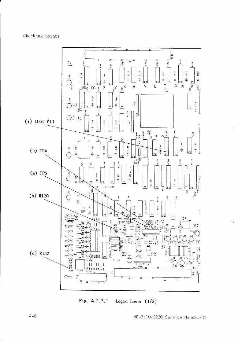
5 0
Check ing po in ts
( i ) rc6T #13
(b) rP4
(a) TPs
(h ) R l20
( . ) R132
Eri.l!.!$*.. -\JPzt-, 6ii: p r [ - l r . x
rx , - \ | . i , | ' . l *v
_ &
ora*-- D+ r'
o3v-\o a E
Tv @d F
l lt ll l . l l .l l s l l :t t t lI l l l l rl n l -
l n l -
R - P Ia r^ l
T - l lt t l
t t lt t ll l e ll l r ll n l I
+ lL
q p gr-l
* l l l l - l r o: l | | l : l l :" l l l l " l l
- r - l | | l r l l - , -- l n l l n l - l n l -
t i l g , 3 5
r l l" t lr l l- l n l
3N 9m i
E r---lt l
t t t l. t t t l: t t t l" t t t l
r I I l - l- ln I
LLrr
v st lt t nt t t l
: | |t t t l- t t t t l
= l l l lt n r l n l
BB; AR 3l l r c
l l n T - ll l l l n l ll l l l ; l ll l l | - r - I Il l I n l - l . ' lH *
g !- [l t-l- r l l - l l
I t : t It t " t lI l l l Il.nj - lnj
L-/I P 6 4
t l
a
:/ 1 1 X ,I l T -
. f
( ) N 6\_-/ ; :
I sU U
t--l r-rt t t ll l " l l .l 1 3 l l C It t t lI l - L I l - !| |
' T l - l T
| | |"Ul n l
-r
l Nf -
n n n t lt t t l t t t lt | | | | | lt | i l t t l
. l l l l l l l l i3 t | | | Lr l l l l l l l l . .- l n l E t d E
3 s p
: I '
Tr
n r-tt t t l| | t lI t l| | t l| | t l| | t lt r t lp l n l
I l rt 1n n
I t ll l s l lI l r l Il.nJ - Lrr.l
m
l f c r r s E
o C l ? O
- - l F
t{
TIt lt l
r t I
E l It lt lg N L J
H I I Ut lt l
n l Ia l Ia t I
t lI IL-.1L J .
; _'.' ;; <
7 ' Y : X
t t _ t lI l : l It t t lI t - ! t I
Ld -'
[-ol:; | . - - - 1
T r t lr l l r l I' l l 5 l I
r l l - ! l I- l l - l l' t n l L d
t nI U
t l!
? ,:.-
q i :
t-tt t
t lt tt lt ll lt.nl
oF
I
q g 3 r - r[ l l . - l
' l l :t t t t t t c
B l l l l ; l l s" l l l l u l l ur l | | l - . ' - l l - . r -- l n i I n l - l n l -
- l I c rsz
T-tut - t s n s T rl l ' l l l l
l l s l l E l lI l r - l l r - l Iln | - hJ
-- l-oj
:r r: lJJ r
f F r . r l .*-:7-\
c5 r a t t u \ - /n n.Y,.Y !'(" 1 r - 1 r
u034'-\
c{ o oE
031,/-\ p{ o .
o:.){ - uD { '
o.J={ - g--__o}4
o.r){ -prH
^-">:<'!:1 N'
c a t tl " l = | ? f i
F---15-___r_i
Logic Lower (I /2)
t a 7
o lc l
5 Sa 9
o
I-r
:-.t--lI I
t lt lt l
t lt n l
I
T
d
T-lt l
- l lo l lu l l
t lr - l ILI-U
J "
( ) - r
TI- l - l I
tJ- Jd
, c t , 5 ,s .l7^\ i- \
TY.V1 1 1 i
I '1D-32 IO / 3220 Service Manual-Ol
F i g . 4 . 2 . 3 . I
4-B

C h e c k i n g p o i n t , c o n t i n u e d
(m) ICTB ro 7L#I4 each
( j) rc8A #ls
(k) rcsA #r4
(f) D5 Cathode
(e) rCzL #7
(") Q2 Base
:Q
9
o- TP6
t lt lt lt lI It lt lt lt l
l n rA
Ex F 3 3
1 - - H H H
I I t-l t-l t-t t-t t-ls l l n l l ; l l n l l x l l ; l lr l l r l l ; l l ; l l r l l ; l l
l l l l l r r r r r r l-r- | I -r- | | -.r- | | r | | -! | | -! I I- l n l - l n l - l n l - l n l - l n l - l n lL K J H G F E D C B
pPDr?z7 . X tO
n 6 n f
t s 3 s 3 * 3 n I! r r H T l ? n x H
n l l n l l n l l n nl l d l l l l e l l l l s l l e l l l l Gl ' , l *H [-l *[.] [,] +H*Lj u
t .
(,)16l-\
)15/z\
l ; / - \
) t ar'b^o-
-'A-<' -l_u) - i
J ^
F ( 91 9 \
l @ r {
o \
t E q
c R r g
, i-rz
YR9 VR8 YR? VR6 YRs VRlxrrr !!II! ruro-
lc f f r rasr l l t r xL.Y | - l !e iJ I rn tsxdp I
VR3 VR? VR II t { _ ( [ Y f L I iL1J!}J
F i g . 4 . 2 . 3 . 2
MD-32 IO/ 3220 Serv ice Manual-01
- i iF U
Ir_.n r-r
ll t i t i t t tt t i t t t t lI r i l t t ll t r l l " r t ll l i i l s | | Il l l l F ; l l II l_ l t_ l rn r L t r-J LIIJ L-J
i : : l ' :
i ; { l
g t t *: l l - Tv l l "
" , I l ( l; r l _ l
- t l ' - ' l o, : , . , r ( l l ; , &, , ; l r 1 r - l
+'u i ' ,.F{ !; l i| . : - I i l \ - ' l c
l l d li _ . | | t r r ft o . p . F t ' | |. - r f - \ ,
| 1 " , ., ro r ' ' J ts : i - l 3 l$ l
f / f c r t r !
'..V lo: l-l +_ , - - _ | |i - t + i l l d lt u r u t t dI N I I Il - c 1 . 8 I I
J I F r r ; | | - . 1,. r--r d'' t-C'l 5-
\ , t -.\_-/ , : .C l a T " N h @
; r r f \ r A , - 3' : L / ' \ - ) -
l It t ll t l
.',ii -_. :;l.--1lgJ-
4-9
( d ) R l
Logic Lower (212)

4 - 1 0 I t lD-32IO/ 3220 Serv ice Manual-Ol

4- l 0 I "1D-32I0/ 3220 Serv ice Manual-O1

5. REPLACEMENT OF MAJOR COMPONENTS
5.1 Antenna unit
When replac ing any component of the antenna uni t , be sure to turn of f thepower complete ly , and take out the antenna dr ive motor fuse. Place a not icel ike ttAntenna is Under Inspectiontt near the power switch of the display r sotha t nobody tu rns the power on ca re less ly .
R e f e r r i n g t o F i g . 5 . 1 , l o o s e n e a c h f o u r ( t o t a 1 e i g h t ) f i x i n g s c r e w s o f t h ef r o n t a n d r e a r a n t e n n a c o v e r s . a n d r e m o v e c o v e r s .
C o v e r
F i x i n g s c r e t ^ tMRT-133 (MD-3210)
l.[RT-133 and I'iRT-134
MRT-134 (MD-3220)
F i g . 5 . 1
5.1.1 Dismount ing t rnasmit ter / receiver (TR) uni t
( a ) T h e T R u n i t i s m o u n t e d r e a r i n s l d e t h e a n t e n n a u n i t . A t f i r s t d i s c o n n e c t
c o n n e c t o r s J 1 o f c a b l e W 1 , a n d J 4 o f \ 1 2 s h o w n i n F i g . 5 . 1 . 1 ( a ) .( b ) R e m o v e L w o f i x i n g s c r e w s o f l h e T R u n i t .( c ) T a k e o u t t h e u n i t a s s h o w n i n F i g . 5 . 1 . 1 ( b ) .
F i x i n g
Bow
+Bow
+
J 4 o f W z
of t.J1
T R u n i t
( a ) ( b )
Fig. 5. I . I Dismounting Transmitter/Receiver (TR) Unit
5.I.2 Replacement of TR unit components
F i g . 5 . I . 2 . I i l l u s t r a t e s t h e 1 0 k W T R u n i t f o r M R T - 1 3 3 ( M D - 3 2 1 0 ) , a n d F i g .5 . I . 2 . 2 r h e 2 5 k W T R u n i r f o r M R T - 1 3 4 ( M D - 3 2 2 0 ) .
( 4 ) + ( 4 )
s c r e w ( 2 )
MD-32L0/3220 Serv ice Manual-O1 5 - 1

( 1) Magnetron IMSFI 4258 ( 10 k\ t / ) or 83564A (25 kW) ]
CAUTION
( a ) K e e p s t e e l o r i r o n t o o l s s u c h a s w r e n c h a n d s c r e w d r i v -e r s m o r e t h a n 2 . 5 c m a p a r t f r o m t h e m a g n e t r o n . U s e n o n -m a g n e t i z i n g s c r e w d r i v e r f o r r e p l a c e m e n t o f m a g n e t r o n .
( b ) A l t h o u g h t h e m a g n e t r o n l o o k s s o 1 i d , i t h a s d e l i c a t e i n -t e r n a l s t r u c t u r e . H a n d l e w i t h c a r e a n d d o n o t a p p l yh e a v y s h o c k .
( c ) A f t e r t h e m a g n e t r o n i s r e p l a c e d , b e s u r e t o p r e h e a t t h eheaLer o f new magnet ron a t leas t 20 minu les on STANDBYc o n d i t i o n .
( a ) P l a c e t h e T R u n i t w i t h t h e m a g n e t r o n s i d e u p .( b ) C u t o f f L h e t i e - 1 a p f i x i n g t h e n a g n e t r o n 1 e a d s .( c ) D e s o l d e r t w o m a g n e t r o n l e a d w i r o . ( n r o a . , ^ . n d y e 1 1 o w ) f r o m t h e p u l s e
t r a n s t o r m e r .( d ) B y r e m o v i n g f o u r f i x i n g s c r e w s ,( e ) F ix a ne l^ / magneLron to the
c h a s s i s , a n d s o l d e r L h e y e l 1 o wl e a d t o p i n # 4 , a n d g r e e n l e a dt o # 6 o f L h e p u l s e t r a n s f o r m e r .I n o r d e r t o a v o i d c o r o n a d i s -c h a r g i n g , t h e m a g n e t r o n l e a d ss h o u l d b e c u t t o p o s s i b l e m i n i -mum length and the w i re endsm u s t b e c o r r e c t l y s o l d e r e d t ot e r r n i n a l s .
( f ) R e f e r r i n g t o p a r a . 3 . 2 . 1 , c a r r yo u t t h e t u n i n g a d j u s L m e n t .
d is rnount and take ou t the magnet ron .
C i r c u L a t o r
L i m ' i t e rP u L s e t r a n s f o r m e r
C o v e r
M o d u L a t o r
I F u n ' i t
D i o d e 0 1
D i o d e 0 2
F c o v e rR e s i s t o r R 1
M a g n e t r o n
Components of 10 kW TR Unit
5-2
F i g . 5 . 1 . 2 . 1
I ' lD-32 IO / 3220 Serv ice Manual-01

(2) Modulator 1239U522368 ( 10 k\,{) or 229U25361 (25
( a ) R e f e r r i n g t o F i g . 5 . I . 2 . I a n dF i g . 5 . 1 . 2 . 2 , d i s c o n n e c t E 1 t oF ,4 . In case o f 25 kW modu la to r ,a l so d isconnec t J3 and J4 .
( b ) R e m o v e s e v e n f i x i n g s c r e w s o fthe 10 kW modu la to r o r n ines c r e w s o f 2 5 k l { m o d u l a t o r . t h e ntake ou t the board .
P u L s e t r a n s f o r m e r
M o d u L a t o r
kw) lJ 4
C i r c u L a t o r
25 kt l r | TR uni t
E 1 t o E 4
C o v e r
M I C
L i m i t e r
"1
S p a c e r
D i o d e
D i o d e
R e s i s t o r
un ' i t
I F c o v e rF a n m o t o r
fv lagnet ron
Fig. 5.I .2.2 Components of 25 kW TR Unit
(3) IF uni r (239U525r2)
(a ) Remove two IF cover f i x ing sc rews and remove the cover .(b ) D isconnec t J2 , remove s i x f i x ing sc rews o f the IF un i l , and
ou t the board . Moun t new un i t i n reverse s teps .(c ) When new IF un i t i s moun ted , ca r ry ou t the tun ing ad jus tment
t o D a r a . 3 . 2 . I .
o1
o2
R1
then Lake
r e f e r r i n g
( 4 ) M I C ( N J T 1 9 4 6 o r S - R X 3 4 )
( " ) R e m o v e t h r e e f i x i n g s c r e w s ( N J T I 9 4 6 ) o r f o u r ( S - R X 3 4 ) o f t h e M I C c o v e r ,and d ismount the cover .
( b ) R e m o v e f o u r f i x i n g s c r e w s a n d n u t s o f t h e M I C , t h e n t a k e o u t t h e M I C .M o u n l n e w M I C i n r e v e r s e s t e p s .
( . ) W h e n n e w M I C i s m o u n t e d , c a r r y o u t t h e L u n i n g a d j u s t m e n t r e f e r r l n g t op a r a . 3 . 2 . I .
C h a r g i n g c h o k e
MD-32 I0 /3220 Serv ice Manua l -O l 5-3

5.1.3 Replacement of S CON (scanner connection) board
The S CON (scanner c ,onnec l ion) boardj , n t e r f a c e s t h e a n t e n n a a n d d i s p l . y ,a s w e l l a s o t h e r b o a r d s i n t h e a n -tenna un i t . IL a lso conta ins the SHFa n d A Z I r e f o r m i n g c l r c u i t s . A s s h o w ni n F i g . 5 . 1 . 3 , f o l l o w i n g c o n n e c t o r sare mounted on Lhe board fo r t rans-f e r r i n g v a r i o u s s i g n a l s .
N y L o n c L i PJ 3
J 2
J 1
S C O Nb o a r dE I :
E 2 :
T 1l l .
J 2 :J 3 :
I n t e r c o n n e c t i o n o f a n t e n n a a n dd i s p l a y w i t h a n l e n n a c . a b l e .Sends ou t d r ive motor power andr e c . e i v e s S H F i n p u t s i g n a l .I n t e r f a c e w i t h I F u n i tI n t e r f a c e w l t h m o d u l a t o r b o a r df n t e r f a c e w i t h A Z I p u l s e g e n e r a -Lor a t the boLtom o f d r ive motor
F i x i n g s c r e w ( 4 )
n t e n n a c a b L e
5.1.3 Replacement of S CON Board
i l
2
R e p l a c e m e n t i s d o n e a s f o l l o w s :
( 1 ) R e f e r r i n g t o F l g . 5 . 1 , o p e nb o w s i d e a n t e n n a c o v e r .
( 2 ) R e m o v e a l l w i r e s o f E l a n dD i s c o n n e c L c o n n e c t o r s J 1 .a n d J 3 , a s w e 1 1 .
( 3 ) R e m o v e f o u r f i x i n g s c r e w stake ou t the board .
Fig -the
E 2 .J 2 ,
and
B o L t ( 4 )'gB r a c k e t
(4 ) When new board i s moun ted , con-f i rm that JUMPER wire is set tothe same s la tus o f o ld board .
5. I .4 Replacement of motor blush
W h e n t h e m o t o r b r u s h i s w o r n , p a i ro f t h e m s h o u l d b e r e n e w e d .
( 1 ) R e f e r r i n g L o F i g . 5 . 1 , o p e n t h eb o w s i d e a n t e n n a c o v e r .
( 2 ) R e f e r r i n g t o F i g . 5 . I . 4 , u n s c r e wb o t h s i d e s m o t o r b r u s h e s a n d r e -p l a c e w i t h n e w o n e s .
5. I .5 Replacement of motor
( 1 ) R e f e r r i n g t o F i g . 5 . 1 , o p e n t h eb o w s i d e a n t e n n a c o v e r .
( 2 ) R e f e r r i n g L o F i g . 5 . 1 . 3 , r e m o v ea l l w i r e s o f E i a n d F , 2 . D i s c o n -n e c t c o n n e c t o r s J l , J 2 , a n d J 3 ,a s w e 1 1 .
( 3 ) R e m o v e a l l n y l o n c l i p s f o r c a b l ea n d b i n d s o f m o t o r w i r e s .
( 4 ) R e m o v e f o u r f i x i n g b o l t s f o r t h ebracket and take ou t the brackeL
5 - 4
f4ot o r
P h o t o - i n t e r r u c t e r
C o v e r
F i x ' i n g s c r e w
F i g . 5 . I . 4
F i x i n gs c r e r . / ( 4 )
B r u s h
\
Replacement of Motor
Nr:r:n
MD-321 0 / 3220 Serv ice Manual-Ol

t o g e t h e r w i t h t h e d r i v e m o t o r .( 5 ) D e t a c h t h e m o t o r f r o m t h e b r a c k e t b y r e m o v i n g f o u r f l x i n g s c r e w s .( 6 ) W h e n r e p l a c i n g t h e m o t o r , d e t a c h t h e p h o t o - c o u p l e r o f A Z I p u l s e g e n e r a -
to r by remov ing two f i x ing screws o f the cover , and then mount the gen-era tor to the new motor .
( 7 ) T a k e r e v e r s e s t e p s o f t h e a b o v e p r o c e d u r e f o r a s s e m b l i n g n e w m o t o r . I no r d e r L o f i x t h e m o t o r a t c o r r e c t p o s i t i o n , i n s e r t a s h e e t o f p a p e r b e -t w e e n t h e m a i n g e a r a n d p i n i o n b e f o r e t i g h t e n i n g t h e f i x i n g b o l t s o ft h e b r a c k e t . C a r e f u l l y a d j u s l L h e g e a r i n g s o t h a t t h e p a p e r 1 s t a k e no u t b y r o t a t i n g t h e a e r i a l b y h a n d , a n d t h e n s e c u r e l y f i x t h e b o l t s .
5 .2 D isp lay Un i t
5.2.1 Contro l panel (MD-3210-7200)
T h e c o n L r o l p a n e l M D - 3 2 1 0 - 7 2 0 0 i sb u i l t i n a L i l t i n g t y p e c a s e u n i t .T h e u n i t i s c o n n e c t e d t o t h e d i s -p l a y w i l h a 7 5 c m l o n g s t a n d a r dc a b l e . T h e u n i L c a n b e d i s m o u n t e df r o m t h e d i s p l a y u n i L e n a b l i n g u pt o 7 5 c m l o n g r e m o l e c o n L r o l . T h ec a b l e c a n b e e x t e n d e d u p t o f i v em e t e r s o n o p t i o n a l o r d e r f o r I o n o
d i s t a n c e r e m o L e c o n t r o l .
R e f e r r i n g L o F i g .c o n t r o l p a n e l u n i ta s f o l l o w s :
2 . I . I , t h ed ismounLed
5-.i ^L 5
D i s c o n n e c t t h e d i s p l a y s i d ec o n n e c - t o r o f t h e c o n t r o l u n i Lc a b 1 e .R e m o v e t w o s i d e f i x i n g s c r e w sa n d t a k e o u t t h e u n i t .
The f ronL f rame and rear cover en-c a p s u l a t e t h e c i r c u i t c o m p o n e n t s .A s s h o w n i n F i g . 5 . 2 . 1 . 3 , t h e m e m -b r a n e s h e e t w i t h t r a c k b a 1 1 , c h a s -s i s , b o a r d o f c o n t r o l p a n e l w i t h 3swi tches and 8 cont ro ls a re assem-
F ig
b l e d l n s i d e t h e c a s e . F o r d i s a s s e m b l i n gl o w i n g p r o c e d u r e :
( 3 ) R e m o v e e l e v e n k n o b s o f t h e c o n -t r o l s a n d s w i t c h e s a s f o 1 1 o w s .
( a ) C a r e f u l l y r e m o v e t h e c a p o fe a c h k n o b w l t h a c u t t e r b l a d eo r 1 1 k e . S e e F i g . 5 . 2 . I . 2 .
( b ) L o o s e n t h e c e n t e r h e x a g o n a lh e a d s c r e w b y r o t a t i n g c o u n l -e r - c l o c k w i s e w l t h a b o x s p a n -n e r o r s c r e w d r i v e r a n d r e m o v et h e k n o b .
( c ) T a k e o u t t h e p a c k i n g .
l " iD-32 L0/ 3220 Service Manual-O1
F i x i n gs c r e w ( ? )
C o n t r o Lp a n e Lu n i t
C a b L e
C o n n e c t o r
Detaching Control Unit
t h o s e c o m D o n e n t s . f o 1 1 o w t h e f o l -
F ig . 5 .2 .1 .2 Remov ing Knobs
( 1 )
( ) \
. 5 . 2 . L . l
W
5-5

( 4 )( s )
( 6 )
R e m o v e e i g h t f i x i n g s c r e w s o f t h e r e a r c o v e r a n d o p e n t h e u n i t .D i s c o n n e c t c o n n e c t o r s J 7 2 0 I , J 7 2 0 2 , J 7 2 O 3 , a n d J 7 2 0 4 o n t h e c o n t r o lp a n e l b o a r d .R e m o v e t e n s c r e w s f i x i n g t h e c o n t r o l p a n e l b o a r d t o L h e c h a s s i s , a n dtake ou t the board . The t rack ba l l i s d isassembled by remov i -ng fourscrews f i x ing the component to the membrane sheet f rame.
R e a r c o v e r
C o n t r o a L
C h a s s i s
F i x i n g s c r e t JT r a c k b a L l
"%a6o Gc sRilVK n o b s a n d p a c k i n g s C p d M e m b r a n e s h e e t
F ra ine
Fig . 5 .2 .1 .3 D isassembl ing Cont ro l Pane l Un i t
5.2.2 Logic upper (l ' [D-3210-700O) and logic lower (t ' lD-3210-7100)
T h e l o g i c b o a r d s a r e m o u n t e d o n t h e r i g h t s i d e o f d i s p l a ] ' . D i s m o u n t i - n g L h eb o a r d s a r e c a r r i e d o u t a s f o l l o w s :
( 1 ) R e f e r r i n g t o F i g . 5 . 2 . 2 ( a ) , r e m o v e 1 4 f i x i n g s c r e w s , a n d o p e n t h e d i s -p l a y c o v e r .
( 2 ) R e f e r r i n g t o F i g . 5 . 2 . 2 ( b ) , d i s c . o n n e c t J 7 0 0 1 o f t h e l o g i c u p p e r . W h e no p t i o n a l g y r o / t o g i n t e r f a c e i s u s e d , a l s o d i s c o n n e c t J 7 O O 2 .
( 3 ) R e m o v e n i n e f i x i n g s c r e w s o f t h e l o g i c u p p e r a n d t a k e o u t t h e b o a r d .
upper
J7002
s c n e w ( 4 )
( a )
J7103
Ioyer
Dismounting Logic Upper/tower
I ' lD-32 I0 / 3220 Serv ice Manual-Ol
R e a r c o v e r
boa r 'd
<x
D ' i s p L a y c o v e n
J 7001
17105
J7 102( b )
s-6
F i x i n g
F i g . 5 . 2 . 2

CAUTION
T h e l o g i c u p p e r i s a s s e m b l e d w i t h a b a c k - u p b a t l e i : y . D o n o t p l a c et h e b o a r d o n c o n d u c t i v e m a t e r i a l s s u c h a s m e t a l l i c o l a t e o r f o i l .
( 4 ) D i s c o n n e c t J 7 I O 2 , J 7 1 0 3 , J 7 I 0 4 , J 7 1 0 5 , a n d J 7 1 0 6 o f t h e l o g i c l o w e rb o a r d .
(5 ) Remove n ine spacers and th ree f i x ing sc rews o f the log ic lower and takeou t the board .
W h e n t h e l o g i c u p p e r ( M D - 3 2 1 0 - 7 0 0 0 ) i s r e p l a c e d w i t h n e w b o a r d , s e t t i n g o ft h r e e D I P s w i t c h e s S W l , S W 2 , a n d S W 3 s h o u l d b e c h e c k e d . I f t h e s e t t i n g d i f -f e r s f r o m p r e v i o u s b o a r d , r e s t o r e t h e s e t t i n g , i f n e c e s s a r y . F u n c t i o n s s e tb y D I P s w i t c h e s a n d t h e i r s t a n d a r d s e t t i n g s a r e l i s t e d i n p a r a . 1 . 5 . 2 .
W h e n t h e l o g i c l o w e r ( M D - 3 2 I 0 - 7 1 0 0 ) i s r e p l a c e d w i t h n e w b o a r d , s e t t i n g s o ff i v e j u m p e r p i n s s h o u l d b e c h e c k e d , a n d c o r r e c t e d i f n e c e s s a r y . F u n c t i o n sa n d i n i t i a l s e t t i n g s t a t u s o f t h o s e p i n s a r e e x p l a i n e d i n p a r a . 1 . 5 . 1 . F u r -t h e r m o r e , t e n c o n t r o l s a n d t w o s w i t c h e s a r e a s s e m b l e d o n l o g i c l o w e r b o a r da s s h o w n i n F f g . 3 . 1 . 1 . A d j u s t m e n t o f t h o s e c o n t r o l s a s w e l l a s s e t t i n g o fs w i t c h e s s h o u l d b e m a d e w h e n t h e b o a r d i s r e n e w e d . T h e a d j u s t m e n t i n c l u d e s :
The power supp ly board is rnouned ins ide the rear pane1. D ismount ing theb o a r d i s c a r r i e d o u t a s f o l l o w s :
R e f e r L o F i g . 5 . 2 . 3 . I
( 1 ) R e m o v e f o u r f i x i n g s c r e w s o f t h e c o v e r f o r t e r m i n a l s o f t h e o p t i o n a lg y r o / I o g i n t e r f a c e b o a r d o n t h e r e a r p a n e l , a n d o p e n t h e c o v e r .
( a ) P u l s e r e p e t i t i o n f r e q u e n c y ( P R F )( b ) T u n i n g( c ) V i d e o i n p u t 1 e v e l( d ) P r e s e t g a i n( e ) S T C( f ) T r i g g e r d e l a y(g ) SHF and bear ing
5.2.3 Power supply ( l ID-3210/ 3220-6000)
T e r m i n a L c o v e rf i x i n g s c r e w ( 4
Te rm ' i na L cove r
J600J6004J6005
R e a n p a n e L
D a t a i n p u tc o n n e c t o n
F i g . 5 . 2 . 3 . 1 Disassenbling Display Rear
S e e p a r a .S e e p a r a .S e e p a r a .S e e p a r a .S e e p a r a .S e e p a r a .S e e p a r a .
O p t i o n b o a r dt e r m i n a L c o v e r
0 p t i o n b o a r dt e r m ' i n a L c o v e rf i x i n g s c r e w ( 4 )
P o w e r c o n n e c t o r
E a r t h t e r m i n a L
R e a r p a n e Lf i x ' i n g s c r e t ^ r ( 1 0 )
Panel
3 . 3 . 3 ( 1 )3 . t . 23 . 3 . 3 ( 3 )- 1 -
J . I . J
3 . r . 43 . 1 . 53 . 1 . 6
MD-32 IO/ 3220 Service Manual-Ol 5-7

( 2 ) R e m o v e f o u r f i x i n g s c r e w s o f t h e t e r m i n a l c o v e r o n t h e r e a r p a n e l , a n do p e n t h e c o v e r . D i s c o n n e c t t h e a n t e n n a c a b l e c o n n e c t o r s J 6 0 0 4 . J 6 0 0 5 .a n d J 6 0 0 6 .
( 3 ) D i s c o n n e c t t h e p o w e r c a b l e c o n n e c t o r a n d e a r L h t e r m i n a l .( 4 ) D i s c o n n e c t t h e d a t a i n p u t c o n n e c t o r f r o m o p t i o n a l n a v i g a t o r , i f u s e d .( 5 ) R e m o v e t e n f i x i n g s c r e w s o f t h e r e a r p a n e 1 , a n d s 1 o w 1 y o p e n t h e p a n e 1 .
R e f e r t o F i g . 5 . 2 . 3 . 2 .
(6 ) D isconnec t connec to rs J6001 , J6002 , and J6003 . In case o f l qD-3220 , a l sod lsconnec t J6009 .
(7 ) De tach the rear pane l f rom the d isp lay un i t .(B ) F ind the power supp ly board rnoun ted on the rear pane1 . D isconnec t te r -
m i n a l s E 1 , F . 2 , E 9 , E 1 0 , E 1 l , a n d E L 2 , a s w e l l a s c o n n e c t o r J 6 0 0 7 .(9 ) Remove f i f t een (15) f i x ing sc rews o f the power supp ly board , and take
ou t the board f rom the chass is .
D ' i s p L a yu n i t
J 6009
J 6007
J 5 0 0 1J 6002
E1?E 1 0
E11E9
J 6003
F i g . 5 . 2 . 3 . 2 Dismounting Power Supply Board
When the power supp ly (MD-3210-3220-6000) i s rep laced w i th new board , thes w i t c h i n g r e g u l a t o r o s c i l l a t i n g f r e q u e n c y , + 1 0 0 V o u t p u t 1 e v e 1 , a n d m a g n e -t r o n h e a t e r c u r r e n t s h o u l d b e a d j u s L e d . R e f e r t o p a r a . 3 . 3 . 1 .
5.2.4 CRT un i t
CAUTION
EHT (ex t ra h igh tens ion) charge may be remained on the CRT anodec a p . P r i o r t o d i s m o u n t t h e C R T u n i t , d i s c h a r g e t h e a n o d e v o l t a g ew l t h a c l i p c o r d o r l i k e .
( 1 ) R e m o v e t h e( 2 ) O p e n t h e
Disc onnectrear pane l
5-8
d isp lay cover by remov ing L4 f i x ing sc rews .r e a r p a n e l w i t h p o w e r s u p p l y . I R e f e r t o p a r a . 5 . 2 . 3 . lJ6001, J6oo2 and J6003 of the power supply and derach rhef rom the d isp lay un i t .
MD-32I0/ 3220 Serv ice Manual-O1

(3 ) F ind two c i r cu i t boards , the CRT ma in board PWD1050A (bo t tom) , and CRTn e c k b o a r d P W D 1 0 5 1 A ( C R T s o c k e t ) i n s l d e t h e d i s p l a y u n i t . F i g . 5 . 2 . 4 . Ishows layou t o f the CRT c i rcu i t boards .
(4 ) D isconnec t connec to rs J7105 and 7LO6 on the log ic lower MD-3210-7100 .Pu11 the cables onto the CRT main board ins ide the uni t .
(5 ) D isconnec t p in #16 o f the CRT neck board and ca re fu l l y remove the CRTsocke t f rom the CRT neck .
(6 ) D isconnec t connecLor P46 I o f the cab le to CRT de f lec t ion yoke .( 7 ) D i s c o n n e c L t h e C R T a n o d e c a p .
F r "om Log i c
C R T
C R T a n o d e c a p
M o u n t i n g p L a t e
P461
P202
F r o m L o g i c L o w e r J 7 1 0 5V ' i deo ' i npu t
CRT main board
P i n # 1 6
T o J 6 0 0 3J 6001
L o w e r J
\lt
7 1 0 6
P201
J 6002C R T S o c k e t
neck boardCRTo
3
\e a rPoHer supply o p a n e L
F i g . 5 . 2 . 4 . I Layout of CRT Unit Boards
( 8 ) W h e n o p t l o n a l g y r o / I o g i n t e r f a c e b o a r d i s m o u n t e d o n t h e l e f t h a n d s i d eo f t h e d i s p l a y u n i t , d e t a c h t h e b o a r d . R e m o v e f o u r ( 4 ) f i x i n g s c r e w s o ft h e m o u n L i n g p l a t e , r e f e r r i n g t o F i g . 5 . 2 . 4 . I . C a r e f u l l y t a k e o u t L h emount lng p la te w i th CRT main board and neck board th rough the le f t hands i d e o p e n n i n g o f t h e d i s p l a y c h a s s i s a s s h o w n i n F i g . 5 . 2 . 4 . 2 .
( 9 ) R e m o v e t w e l v e ( I 2 ) f i x i n g s c r e w s o f t h e C R T m a i n b o a r d a n d d e L a c . h L h eb o a r d f r o m t h e m o u n t i n g p 1 a t e .
( 1 0 ) R e f e r r i n g t o p a r a . 5 . 2 . I , d i s m o u n t t h e c o n t r o l p a n e l u n i t . D i s m o u n t t h eb r a c k e t b y r e m o v i n g f i v e ( 5 ) f l x i n g s c r e w s .
( 1 1 ) R e m o v e t e n ( 1 0 ) s c r e w s f i x i n g t h e f r o n t f r a m e t o t h e d i s p l a y c h a s s i s .
Securely hold the front frame and carefully draw it out with CRT. Besure that the CRT is so heavy.
P lace the CRT wi th the f ron t face o f the f rame bot tom.( I 2 ) R e m o v e f o u r ( 4 ) f i x i n g n u t s o f t h e C R T a t i t s c o r n e r s , a n d t a k e o u t a s -
s o c l a t e d w a s h e r s .( 1 3 ) S l o w 1 y l i f t u p t h e C R T a n d d e t a c h f r o m t h e f r o n t f r a m e .( 1 4 ) F o 1 1 o w t h e r e v e r s e p r o c e d u r e f o r m o u n t i n g n e w C R T a n d C R T b o a r d s .
MD-3210/ 3220 Serv ice Manual-Ol 5-9
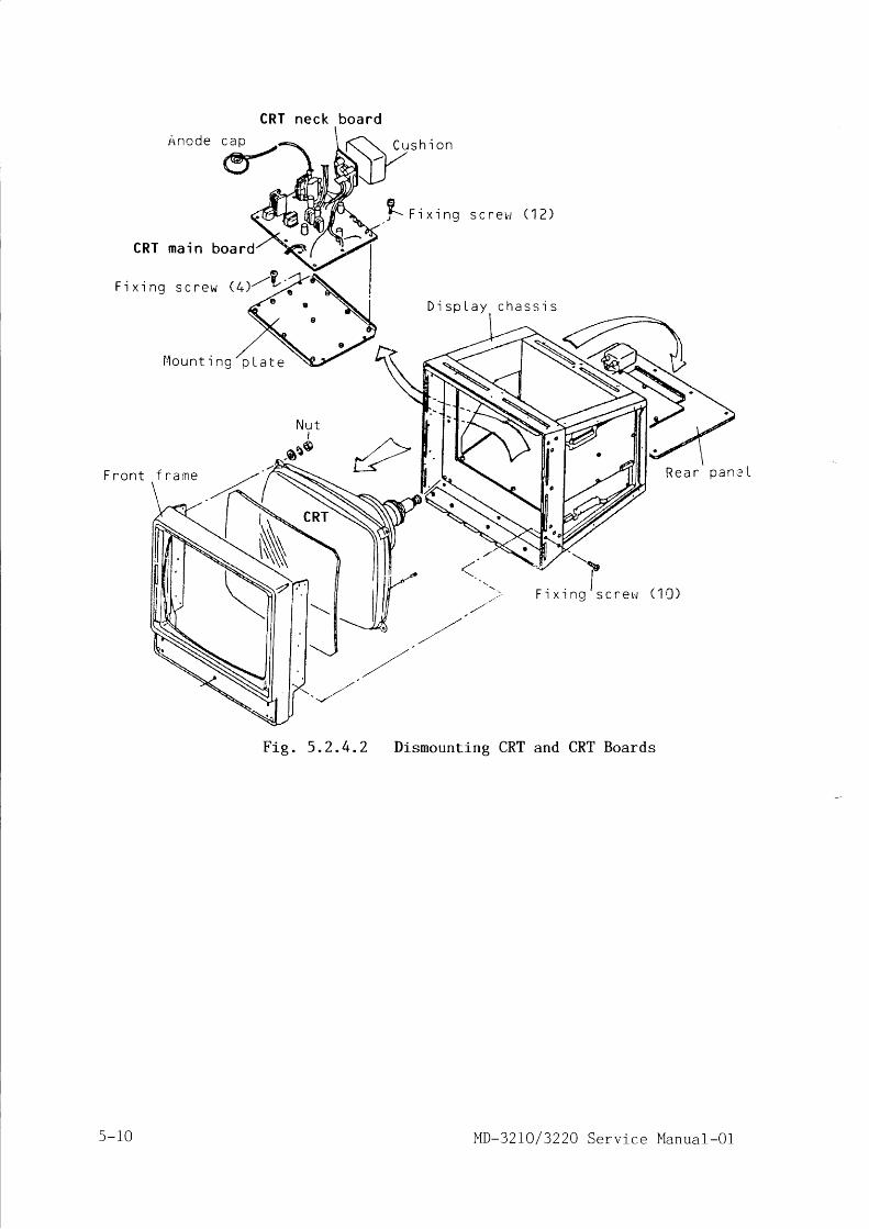
H n c d e
C R T m a i n b o a r d
c a o
€
CRT neck board
C u s h ' i o n
F i x i n g s c r e b r ( ? )
c h a s s i s
F ' i x
F i g . 5 . 2 . 4 . 2 Dismounting CRT and CRT Boards
F i x i n g s c r e w @ / U ;
l ' l oun t i ng
F r o n t R e a r p a n - ' L
-Il n g s c r e t J ( 1 0 )
D i s p L a y
p L a t e
f r a r n e
s -10 MD-32 I0 / 3220 Serv ice Manua l -O l

6. TROUBLESHOOTING
A s r n o s t c i r c u i t s o f t h i s r a d a r a r e c o m p o s e d o f i n t e g r a t e d c i r c u i t s ( I C ) , i L
is ra ther d i f f i cu l t to loca te de fec t ive components w i th usua l ins t ruments
s u c h a s a n o s c i l l o s c o p e o r m u l t i - m e t e r . I n o r d e r t o r e s t o r e t h e s y s t e m i n
t r o u b l e t o n o r m a l o p e r a t i o n a s q u i c k l y a s p o s s i b l e , t h i s s e c t i o n e x p l a i n s
f l o w c h a r t s a n d t a b l e s f o r l r o u b l e s h o o t i n g b a s e d o n r e p l a c e m e n t o f p r i n t e dc - i r c u i t b o a r d s .
F o r t r o u b l e s h o o t i n g m e a s u r e m e n t , p r e p a r e a n o s c i l l o s c o p e , f r e q u e n c y c o u n t e r ,
a n d / o r a m u l t i - m e t e r w i t h i n t e r n a l r e s i s t a n c e o f 2 0 k n / V D C , a c c o r d i n g t o r e -
s p e c t i v e d e s c r i p t i o n s .
6. f Troubleshooting by Observing Display
I f the radar shows abnor rna l opera t ion , somet imes the cause o f ma l func t ion
c a n b e f o u n d b y c a r e f u l l y o b s e r v i n g i m a g e s s h o w n o n t h e C R T o f t h e d i s p l a y
u n i L . R e f e r t o f l o w c h a r t s a n d t a b l e s i n t h i s p a r a g r a p h f o r a n a l y s i n g L h ef a u l t s .
( 1 ) R a d a r d o e s n o t c o m e o o , a l t h o u g h P O W E R s w i t c h i s p r e s s e d .
Ship 's power source
Power supply MD-321013220-6000Yes
Control panel MD-3210-7200
Power supply MD-3210/3220-6000
Yes
( 2 ) C R T i s n o t 1 i t u p
S T A R T
is sh ip ' s ma ins vo l tage+ 10% of normal value ? Sh ip ' s ma ins supp ly i s t roub le .
Is the main fuseb lown ?
FET Q1 to Q4 , o r d iode D1 to D19 ,D33, D34 may be defect ive.
Is the voi taee betweenJ7104 #1 and #2 o f loe ic lower
MD-3210-7000 as belol t ?POI.JER switch pressed: 0 VP0WER switch open: 12124 Y
Check for cont inu i ty o f cab ies .Check the membrane sheet.
Check E3-E4 & E6-87 connect ions.IC3 and i ts related components maybe defect ive .
S T A R T
D4 to D11 may be defect ive.+100V and/or +50V 1 ine may be short-c i rcu i ted to ground.
Are +100 V and +50 Vnormal ?
supplyMD-3210i 3220-6000
MD-32L0/3220 Serv ice Manual-O1 6-1

7
Yes
Yes
Yes
(3 ) Abnorma l d i sp lay on CRT
CRT unit
CRT un i t
Power supply MD-3210/3220-6000
Cont ro l pane l MD-3210-7200
Yes
Logic upperLogic lower
MD-3210-7000MD-3210-7100
Does CRT f i lamentl isht ?
Neck board is improper ly f i t ted.Cable between CRT uni t and J6003of power supply may be defect ive.
Is waveform at J7105#1 as shown in para.
4 . 2 . 3 ( 2 ) ( c ) ?Inproper f i t t ing o f the neck board.Cable between CRT uni t and J7105of log ic lower may be defect ive .MD-3210-7100 VRg may be defect ive .
Are +12 Y, -72 V and+5 V suppl ies normal ?
Respec t i ve rec t i f i e r c i r cu i t s .
Are vol tages of J7104 #7 to#10 as shown below ?
Br i l l i ance con t ro lfu1 ly CCl l l : 0 Vf u l l y C W : 5 V
MD-3210-7200 may be defect ive.Improper cab le connect ion.
Logic upper board may be defect ive.Video output of logic lower boardmay be abnormal.Check cable between J7001 and J7106.
N o . Trouble Cause Action
1 Pic tu re on CRT isno t s tab l l : . zed andmoves up /down orl e f t / r i g h t c o n t i n -u o u s l y .
( a ) I m p r o p e r s e t t i n g o fCRT s ize
( b ) I m p r o p e r s e t t i n g o fhorizontaT- scanning
( . ) L o o s e c o n n e c t i o n o fcab le be tween J7106and CRT un i t .
(d ) Improper ad jus tmento f V . H O L D a n d H . H O L Dof CRT ma in board .
(e ) Fau l t o f l og ic lower
Turn OFF SW3 #7 ofl o g i c u p p e r .
S e t J u m p e r J P 5 o f 1 o g -i c l o w e r t o 1 , 1 5 3 .
S e c u r e l y c o n n e c L t h ec a b l e p l u g s .
A d j u s t c o r r e c t l y .
R e p l a c e t h e b o a r d .
2 Marker r ings inthe p ic ture ared i s t o r t e d .
(a ) Improper ad jus tmento f V . S I Z E , V . L I N E ,S . C O R R E , a n d H . W I D T H .
(b ) Improper ad jus tmento f CRT neck co res .
A d j u s L c o r r e c t l y .
A d j u s L c o r r e c t l y .
6-2 MD-32 I0 / 3220 Serv ice Manua l -01
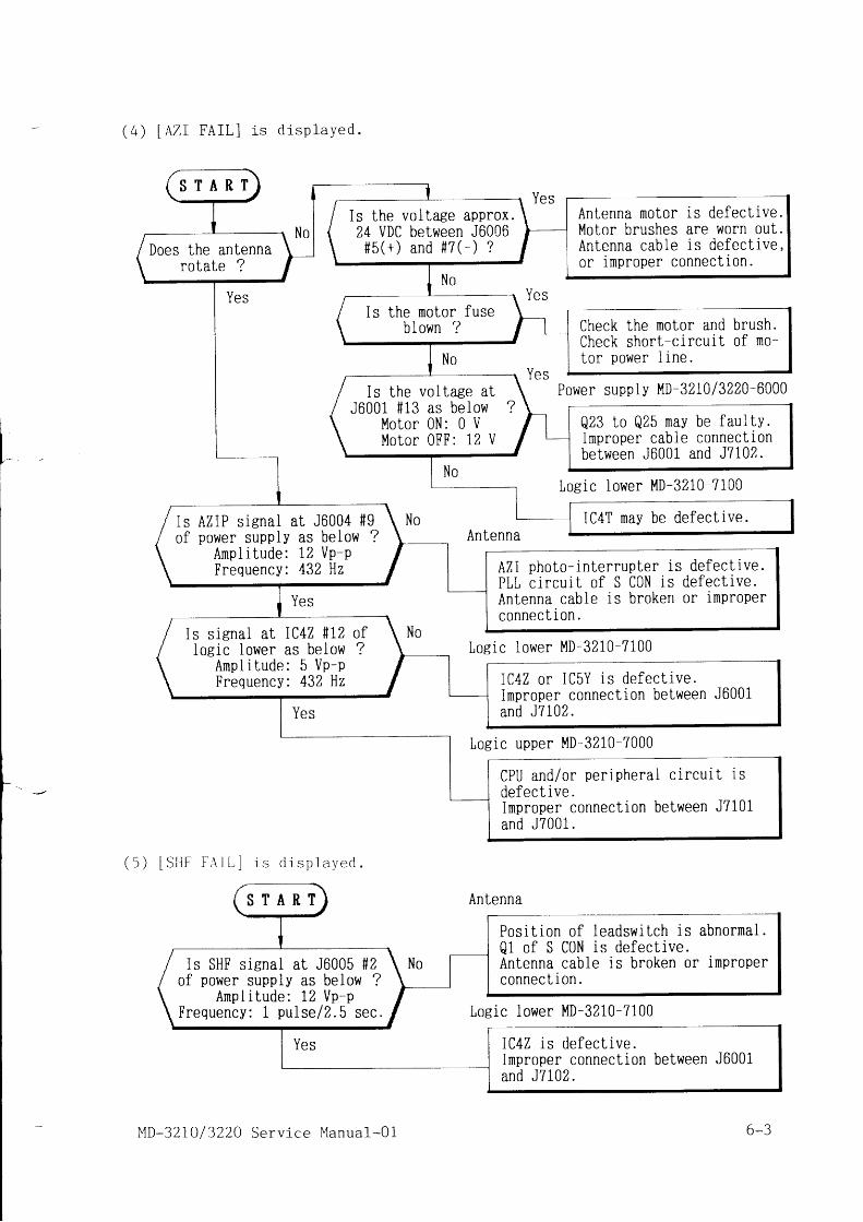
( 4 ) I A Z I F A I L I i " d i s p l a Y e d .
Yes
Yes
Yes
( 5 ) [ S I I F F A I L ] i " d i s p l a y e d .
Yes
Power supply MD-32I013220-6000
Losic iower MD-3210-7100
Loeic lower MD-3210-7100
Logic upper MD-3210-7000
Antenna
Yes
Yes
Yes
Antenna
Ir - . *|
-r/
Posi t ion o f leadswi tch is abnormai .Q1 of S CON is defect ive.Antenna cable is broken 0r improperconnect ion.
Loe ic lower MD-3210-7100
S T A R T
Antenna motor is defect ive.Motor brushes are worn out.Antenna cable is defect ive,or improper connect ion.
Is the vol tase approx.24 VDC between J6006# 5 ( + ) a n d f 7 ( - ) ?Does the antenna
rotate ?
Is the motor fuseblown ? Check the motor and brush.
Check short-c ircui t of mo-tor power l ine .
Is the vol tase atJ6001 #13 as below ?
Motor 0N: 0 VMotor 0FF: 12 U
Q23 to Q25 may be faul fv.improper cable connect ionbetween J6001 and J7102.
IC4T may be defect ive.Is AZIP s igna l a t J6004 #9of power supply as beiow ?
Ampl i tude: 12 Vp-pFrequency: 432 Hz AZI photo- interrupter is defect ive.
PLL c i rcu i . t o f S CON is defect ive .Antenna cable is broken 0r improperconnect ion.
Is s iena l a t IC4Z * I2logic lower as below
Ampl i tude: 5 Vp-PFrequency: 432 Hz IC4Z or IC5Y is defect ive .
improper connect ion between J6001and J7102.
CPU and/or per iphera l c i rcu i t i sdefect ive .Inproper connect ion between J7101and J7001.
S T A R T
is SHF sienal at J6005 #2of power supply as below ?
Ampl i tude: 12 Vp-pFrequency: 1 pu l se l2 .5 sec.
IC4Z is defect ive .Improper connect ion between J6001and J7102.
MD-32 I0 /3220 Serv ice Manua l -O1 6-3

( 6 ) P o o r s e n s i t i v i t y , e v e nSTC and FTC suppress ion
g a i n a n d v i d e o c o n t r o l s a r eL o m i n i m u m .
s e t L o m a x i m u m . w h i l e
S T A R T
Yes
Control panel
/Rr . vol tages at every\vut#7 of ICZL, 31, 4L t - -
, A / D . t r " . . t . d 5 V ? t
l N o
Improper contact of con-t ro l pane l cab le .VIDE0 cont ro l o f the con-t ro l pane i is defect ive .
Control panei
/ Is the vol tagei J6004 #2 as below1 No ise i eve l : 0 .6\ V i d e o l e v e i : 3 . 5
ut, \
,l-, /No I
#
\
at J6004 #3, \ Y . tas be low ? \max to 0V min l-max to 0V min Imax to 5V min/
re voltagesi l4, and #5( G A I N ) : 5 V
4 ( S T C ) : 5 V5 ( F T C ) : 0 V
Improper contact of con-t ro i pane l cab le .Fault of respect ive con-t ro ls o f the cont ro lpane l .
Loeic lower MD-3210-7100No
Improper adjustment of theana log v ideo c i r cu i t ., / ^' Does tune meter show
' tun ine po in t ?\ -
YesLogic lower MII ^ - T n I t
-3210-7100nlenna)
Nobu5 r r d l i l p .
Improper adjustment of iogic lower.Improper adjustment of Log IF amp.Go to Antenna
Lroubleshoot ing 6 .3 .
6.2 Operat ion Control Troubleshoot ing
T f ^ n A 1 2 t . i o n a 1 c o n t r o l o f t h e r a d a r s h o w s m a l f u n c L i o n , t r o u b l e s h o o L l n g i s
c a r r i e d o u t a s f o l l o w s .
( 1 ) A U T O T U N E d o e s n o t o p e r a L e .
Try AUT0 TUNE ad jus tmen t f i r s t i n pa ra . 3 .2 .1 .
Control panel
Yes Yes Logic lower MD-3210-7100
Yes
Loeic lower MD-3210-7100Yes
Antenna
S T A R T
Can TUNE controlselect AUT0 or l'lANtun ing d isp lay ?
TUNE cont ro l (VR4) is defect ive .
Is manuai tuningoperat ion poss ib le ?
Does tuning indi-cator operate ?
Adjustment of tuning cir*cu i t i s no t co r rec t .IC5R is defect ive .
I s TUNE .M vol t,aeeat J6005 #4 approx.
0 t o 3 . 5 V ?IC3N, IC5K are defect ive .
Tune meter l ine is broken.L o g I F a m p . u n i t i s f a u l t y .
6-4 MD-32 IO/ 3220 Serv ice Manua l -O1

Yes
( 2 ) G A I N c o n t r o l d o e s n o t o P e r a t e .
Yes
( 3 ) S T C c o n t r o l d o e s n o t o P e r a t e .
Yes
(4 ) FTC con t ro l does no t oPera te .
Yes
Power unit MD-3210/3220-6000Loeic lower MD-3210-7100
Antenna
Loeic lower MD-3210-7100
Cont ro l pane l MD-3210-7200
Logic lower MD-3210-7100
Control panel MD-3210-7200
Loeic lower MD-3210-7100
Control panel MD-3210-7200
Is TUNE'0 vo i taeeat J6005 S3 aPProx.
2 2 t o 3 0 V ?Power uni t +35 V suPPlY is faul tY.Logic lower IC3N is defect ive.
Improper connect ion of antenna cable.Log IF amp. , MIC, or Magnet ron maybe defect ive . Refer to Para. 6 .3 .
S T A R T
Ga in con t ro l c i r cu i t Q39 , Q16 , D10 ,or related parts may be defect ive.
I s GAIN con t ro l vo l t -age at J7104 #3 varies
f r o m 5 t o 0 V ?
GAIN cont ro l VR1 may be defect ive .Improper connect ion of cable betweenJ7201 and J7104.
S T A R T
Improper adjustment of I-STC-TETI VRzanh rcTe-TT[El vm. Rerer to s. z. s.STC c i r cu i t Q8 to Q10 , IC1L o r re -lated parts may be defect ive.
Is STC cont ro l vo l t -age at J7104 #4 varies
f r o m 5 t o 0 V ?
STC control VRZ may be defect ive.Improper connect ion of cable betweenJ7201 and J7104.
S T A R T
Is FTC cont ro l vo l t -ase at J7104 #3 varies
f r o m 0 t o 5 V ?
FTC cont ro l c i rcu i t QZ to Q4, Q40,or related parts may be defect ive.
FTC control VR3 may be defective.Improper connection of cabie betweenJ7201 and J7104.
MD-32 LO/ 3220 Service Manual-Ol 6-s

(5 ) VRM does no t opera te .
Measuring pointMD-3210-7200
Sl.l1 #3: Sisnal#2: Ground+ 5 v - n
O V - J L
( 6 ) E B L d o e s n o t o p e r a t e .
Yes
Measuring pointMD-3210-7200
Sltlz #3: Signal#2: Ground
+ 5 V - nt l
O V - - l L
( 7 ) T r a c k b a l l d o e s n o t o p e r a t e .
Yes
MeasurinB pointMD-3210-7200 Track bal l#3 , #4 , f 5 , #6 : S iena l
#2: Ground
6-6
Control panel MD-32i0-7200
Yes
Control panel MD-3210-7200
Losic upper MD-3210-7000Yes
Control panel MD-3210-7200
Yes
Control panel MD-3210-7200
Loeic upper MD-3210-7000Yes
Control panel MD-3210-7200
Logic upper MD-3210-7000
Yes
+ 5 V
O V
S T A R T
Membrane sheet or its con-nect ion cab le is defect ive .Does VRM 0N/0FF
switch operate ?Is s igna l as be low ?
0 N : 0 U / O F F : 5 V
Control panel MD-3210-7200may be defect ive.
Is waveform of VRMencoder output as
shown left ?EBL SltI1 may be defective.
Loeic upper MD-3210-7000maV be defect ive.
S T A R T
Membrane sheet or its con-nect ion cab le is defect ive .Does EBL 0N/0FF
switch operate ?Is s igna l as be low
0 N : 0 V / 0 F F : 5
Control panel MD-3210-7200may be defect ive.
Is waveform of EBLencoder output as
shown left ?EBL SW2 may be defect ive.
upper MD-3210-7000defect ive .
S T A R T
Track ba l l i s defect ive .Improper connect ion of t rack bal iand J7202.
Is waveform of trackbal l output as shown
below ?
Loeic upper board may be defect ive.
_JlMD-32 IO / 3220 Serv ice Manua l -O1

(8) Dimmer lamps cannot be turned 0N.
Yes
Yes
Control panel MD-3210-7200
Logic iower MD-3210-7100
Control panel MD-3210-7200
Yes
6.3 Antenna Troubleshooting
W h e n i t i s e s t i m a t e d t h a t m a l f u n c t i o n o f r a d a r i s d u e L o L r o u b l e o f a n t e n n au n i t , t r o u b l e s h o o L i n g i s p e r f o r m e d a s f o l l o w s :
( 1 ) A n t e n n a d o e s n o l r o l a t e .
F o l l o w L h e f l o w c h a r t i n p a r a . 6 . L ( 4 ) A Z I F A I L t r o u b l e s h o o t i n g .
( 2 ) P o o r s e n s i L i v i l y c a u s e d b y L r a n s m t t e r / r e c e i v e r L r o u b l e i s a n t l c l p a t e d .
Power supply MD-32I013220-6000
Yes
Yes
Power supplyMD-3210/3220-6000
S T A R T
Is DiM swi tch outputvol tage as beiow ?0 N : 0 V / O F F : 5 V
Membrane sheet may be defective.
Does DIMMER vol tageat TP1 of loeic lowervar ies cor rec t ly ?
DIMMER cont ro l c i rcu i t IC5P, IC3Nor related parts may be defect ive.
Trans is tor Q1 may be defect ive .Improper connect ion between J7201and J7104.
Does vol tage at com-mon 1 ine of DS1 to DSgvar ies cor rec t ly ?
Lapms DS1 through DSg may be blown.
S T A R T
Is MOD.S +300 V a tS CON E1 #17 OK ?
KZ or Q26 may be fau l ty .Improper connect ion of an-tenna cab le .
Is l'lOD fuse F3 ofpower supply blown ?
Pulse leneth is not se lec t -ed with detect ion range.
Log ic l ower : IC5V, IC4T ,Q35, Q36, Q37
Modu la to r : K l , K2 , K3Improper adjustment of [TRl'-]VR10 of log ic lower .Modulator SCR/diode are de-
fec t i ve .10 kl t l : Q9, Q1025 k l t l : Q9, Q10, Q11
Is magnetron heatervoltage between leadw i r e s 6 . 3 V + 1 0 % ?
Magnetron heater constantcu r ren t c i r cu i t IC5 , 832 ,or related parts may bedefect ive .
MD-32IO/3220 Serv ice Manual-O1 6-7
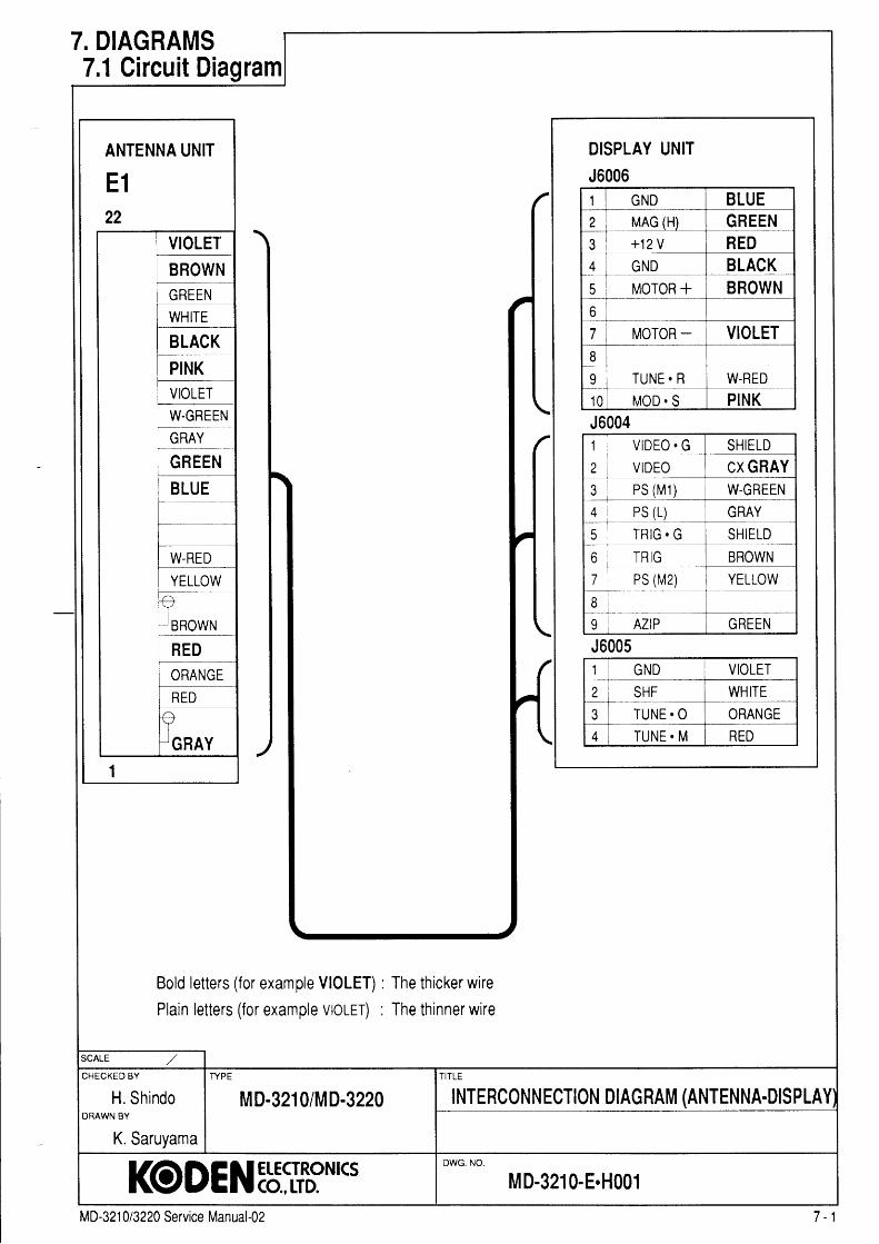
ANTENNA UNIT
E122
VIOLETBROWN
W.GREEN
/. DIAGRAMS7.1 Gircuit Diagram
Bold letters (for example VIOLET) : The thicker wire
Plain letters (for example vtotrr) : The thinner wire
DISPLAY UNITJ60061 GND BLUE2 MAG (H) GREEN3 +12 V RED4 GND BLACK( MOTOR + BROWN6
7 MOTOR - VIOLET8
I TUNE. R W-RED{ n MOD. S PINKJ60041 . V I D E O . G SHIELD
2 VIDEO CX GRAY{ P S ( M 1 ) W-GREENA.+ PS (L) GRAY5 T R I G . G SHIELD
o TRIG BROWN7 PS (M2) YELLOW8
I AZIP GREENJ6005II GND VIOLETI SHF WHITE3 TUNE. O ORANGE
4 TUNE. M RED
CHECKED BY
H. ShindoTYPE
MD-3210/MD-3220 |NTERCoNN ECT|oN D|AG RAM (ANTENNA-DIS PLAYDRAWN BY
K. Saruyama
I(ODENEb::ItrN*SDWG. NO.
M D-3210-E.H001
MD-321 013224 Service Manual-02 7 -1

ADDRESSDE CODER
MARK E R
V- RAM
MEMORY
CONT ROL
PANE LI NTERFACE NUMER I C
V- RAM
A D D R E S SSELECTOR
R A D A R
V- RAM2MEMBRANES'# I TCII
RA DAR
V- RAN1l
R A D A R
V- RAI''10ADDRE SSDE CODE R
T R A I L
V- RAMM E M O R YCONT ROL E R
COMPARAT OR
E XPANDE R
L . P . FCONT ROLER
TX. DELAYCONT ROL i t r ;ur
A 0 - 1 9
C R T C
H D 6 3 4 B 4
MAo- 1 I
AZI
| | + 5 Vi i + B V
I + l z v1 ^ 1 ,
I | - L l y
T r \I U
GY RO I l F
D I SPLAYU N I Ti l R D * 6 2
VCKE X T
SYNC
|-_-] si n r \ /I
u t I
i
I
: a n / t -i u r va 2 r n i i u L u - . l
. . \ - q ' - r \ u w l
- - - l^ v J i t J
D 0 - 8
L S I
K C D - 2 4
AZI
I l? ---'l1 l a I ir i 3 L - I i l t t z t T T l l l . - " 1- i l r ' - l l r l i l : : li l i ! t _ - l l v r sI I I i I i t v Y r .i I i I I I l v v r o| { I I I I l Y t o ' - ;
l l! i r - - f - l - - - - l , - - ' . 1 - - - - ;I t r . r . , , l I i i - L ' ' ' u n i i ;n . o r :u I i
- i ) ! , ' ! 1 , . - l
' iI t r . , : : ' [ - i L ' f
i " ; i
f_-- rsHFApw i
- i " ' I
| | l . n N T R n r F R I:- - r - - r ' - - - " r PWH L U I \
r F . u L c n i P Wi i
TI]RESHOLDCONT ROL E R
E X PCONT ROT ER
i i r u N E . M
DCPO\vE RSU PPLY
M D - 3 2 1 0- 6 0 0 0
+ 100v+ 50vT UNEIUNE. Mt K t b
I F O L I T
MOD + 3 0MAGS H FlYl0T 0RAZI
r *I L l r { :
t J f V
P\V
a \ | l l
U A i i \
C C T
F I I I FI I L I L
- b 1 0 0l r r - e rL1 '^
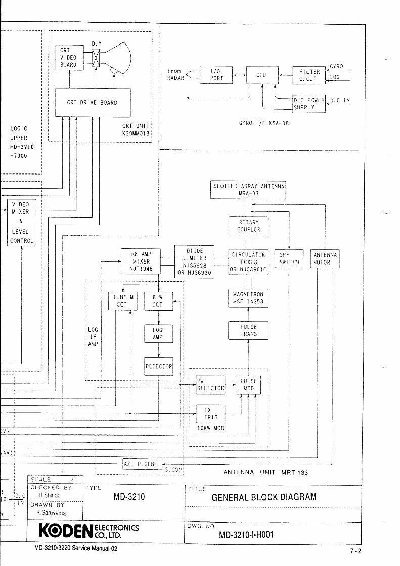
D . Y
C R T U N I TK2OMMOl B
G Y R 0 | l F K S A - 0 8L O G I C
U P P E R
t /D-3 21 0- 7 0 0 0
I SLOITED ARRAY ANTENNAM R A - 3 7
ROT ARY
t Y ) I
i-----+----
I
l l t \ / l l- L
II
-_T=_
I
I
I
I
I
l rl t
? l l' I r n
^ | t u -l j K + -' " l r l
I r 't li l lt l l
II
A N T E N N A U N I T M R T - 1 3 3
L
N
RF AMPM I X E R
t t t T ! n r -t \ J i I J q o
D I O D EL I M I T E RN J 5 6 9 2 8
O R N J 5 6 9 3 O
MAGNE T RONM S F 1 4 2 5 8
p i l t s F
T RANS
ANT E NNAM O T O R
C R TV I D E OEOARD
C R T D R I V E E O A R D
V I D E OM I X E R
&
L E V E L
CONT ROL
S C A L E , /C I . l E C K E D B Y
H ShindobnAwr i B t - -
- -
K.Saruyama
T Y P E
M D-3210T I T L E
GfNEHAL BLoCK DIAGRAM
D W C . N O .
MD-3210-1.H001I(ODENEb::Itr*CSM D-32 1 0 13220 &rvice Manuat -02 7 - 2

L O G I C
UPPER
MD-32- 7 0 0 0
f' r"-1 MrxEFI
l aII L E V E LI
I C0NTRtt--T_
I
IiIIIiIIIIIIIIIIIIII
: _ : _ - - - -
:--F---i-
- - l'J1--:--
;-_i-
?.er)i-j--
II
rrom .-{-t-]rc-]l f *--l #RADAR= poRT
[_l Lru
, f - c.c.r l* ! ! !_
. - l]-L='
i ' -D.c
Po\ , /c tu- D. c tNL--f3y3LY___f---
GY RO I l F K S A - 0 8
It :l l
p l l'
| ' n
i
r ^ |l t ] F € + -
, I t l| : l l ll l
I r- l t
i J i
S C A L S , /
C F l E C K E O B Y
H.ShindoT Y P E
M D-3210T I T L E
GENEHAL BLOCK DIAGRAMD R A W N B Y
K.SaruyamaI
I(ODEN:b::If,?NICS D W C . N O .
MD-3210-1.H001MD-321 0/3220 &rvice Manual-O2 7 -2

A 0 - 1 9
t uG Y R O
MEMERANESlv I ICH
t l F
D I S P L A YU N I TM R D - 6 8
MA0- 1 9
M i M O R YCONI ROL E R
I U N ET UI'IE . M
+ l 0 0 v+ 50v
I R I GI F O L I I
MOD+ 3 0 {MAGu t t l
uqrqRlr4 - 7 |A L I
P\{
i_ i t lEF i L T E I1,,1D-32- 6 1 0 0
L F _ 2 I
ADDRESSDECODE R
D l v l l a1 l 1t l L
EXTV C K I S Y N C
D I VI I 2r11
l iD K
V
II
0 - 7
Y 8 . sX E YDE CODE R
E B LV R M
CONT ROLCCT
E B LVRM
i l ii I - - - - r i
I t i.r ni,' 'n i --;i i
I l s s r r , ^ r n o l I' > l - - L L w I v r \ F _ n, - - - - rcRCo
IA n t r |
GDO- 2A 0 - 5
L ) l
K C D - 2 4
LAMP
C R T B R I L L
T U N EG A I Nc T c
F T C
M D - 3 2 1 0- i 2 0 0
MARKER
V- RAIi|
P A N E LI NI E RFACE MEMORY
CONI ROL
NUMER I C
V- RAM
A D D R E S SS E L E C I O R
R A D A ?
V- RA {2
RA DAR
V-RAMi
R A D A R
V- RAMOADDRE SSDECODE R
T R A I L
V- RAM
TX. DELAYCONT ROL
| . -t lt ll !l lt tl lr li lt lt lt lt lt lt l
<-]-_-|F__--
- l ' + 8 vi i + l ? v
TH RE SHOL DCONT ROL E R
COI , IPARATOR
DCPO\vE Rq t l p p r v
brD-3210- 6 0 0 0
L . P . FCCNT ROL T R
EXPANDI R
TUNI. M
L O G I CLOuiERMD-3 2 I 7 1 0 0

i i i ii i I E 0 A R D r r u - \ / t t f - - - , c Y R o
l i T T Y i l n ; r 'ii | | | | '-----r----r-i ' - 4 4 - - ] i i I I Il i t I t t ) | l ,l l l c R T D R , ' E B . ^ R D I i i t . - - l t j , l 9 9 - " ] - s ! !i i l , - I i i
- - - - - - . t : r - : i - - r
i I -f[J--lT
.^t tt,tl I cYR' r/F KsA-08L o c r c i i l l l l t i i o u u o i a i IU P P E R i I I I I I I I ;
| - - - - - r - l - i - - - - 1 - 1 - - - - - - - - - - - _ - - - - |M D - 3 2 r 0 i | | I I I l _ . _ _ _ _- 7 o o o I i l l l l It t t t lj | t l t l
t t t t t i _- - - - - - - - - - - - 1 l l l l l I l s L o t t t o r R R n v r H t r l l r l
I l l l l i I M R A - 3 I Ir l l l r l l- l i l r f f i p l l I F
I I l i f - J I l R o r A R Y I | |l . r u , ' - l i l - - - - - - - i i c o u P r r n l I Il c o r r n o t l i l l i - - l l I Ir _----J I t t t t t t I| ' r r r ^ ' " 9 : " 1
b R c u L A r o R - l E ; - l [ N t E N * lI i l l i - - J i i f f | ' i u i ' ' ^ p - - 1 F c x 6 8 t t s w r r c H l t v o r o n II i l l i I l s n x r a f - s - r - x r z [ _ l l - f rI i l l l i - i | ' - - - ' l - - r - i l lt r t t t l t t t t t l| | | I I ' - _ - - i _ - _ _ - _ - _ - - - - - - - - - t - - - - - - - ' | | | | It , t l t ' t - - - i , t i t t l
I i l l i i l r___-""trr t_l i T-^,,r i .Onl i I II i l l i i l l c c r l l c c r n i ; " i " L l I | |I i l l l i l - f l - - r - l l I I 1 rI i l l l i I I | .= l - - - - l i f ' j -1*-= l | | Il l l l i i i T l l l l i f f i l l i l i R a N ' l l r lI i l l i r m e l l l T l i 1 I l ll i l l i i | t r , t i l l l l
: j j l l l i | | | l o r r c r o n l l l ' i , | | I: : : , - - - - - ' l l l i t l t - r : L i l r - - r r * i , l l | | I- i - l l ' - [ - - - ' ] - - - l - - - - - - - - l - - - - -F l l s rL tc ron l - l uoo l i I I I- - - - r r l I | | l i i - f f i l I I If f i l l l l i i - l l l i l l l# i I l j i . l r x I t l l i I | |l i t t ' ' l i l r l l l
' r i i ' z s - . , " " ' l l j l l li T= - -__ . ,1 l l l lnli--t- l-+- i i lur p-cENE.L i
i I i =s . coN i ANTENNA uNtT MRT-134- r i l scn r F . / |. l it ^ l i o . c' [ i *
I rj l iI
C I I E C K E D B ' /
H.ShindoT Y P E
MD-3220
T i T L E
G-INERAL BLoCK DlAGloyD N A W N B Y
K.SaruyamaI
I(ODEN:b::ItrNICSD W G . N O .
MD-3220-1.H001
7 - 3MD-321 0/3220 Service Manual-02

J I
1,'4'
HOO. PCBU?I OKI{ TYPE2 ? a r r q 2 2 ? A R
F
X : ( J
sg33g O N _
Lrl uJ t! l-d
Fzf,
5Lao
P r r l | | |#r
1 ' - - - - ' t 0
LOG 1 F RHPrcB U IZ 3 9 U 5 Z 5 I ZI , 2 , 3 , t ,r-T--r-T-*r-]
r z l I I l l I
RJLSE TRI]NST I
2 4 T 1 2 2 8 3 8
0 r 0 2HVR-3H2 HVR-3HZ
v7I lFGNETR0N
It jKI4 TYPEH S T I 4 ? 5 8
C IRCUIJ.RTORU4 FCX6Bo r N J C 3 9 0 l CL I H ] T E RU5 NJS692Bo r NJS6938
TORNTENI.IR
I F
+ 4 V - + 2 4 V
GND
+ 5 V
HON 1 TORTR UNITU'I Ftfl
U 3NJT 1 946
* uoron r-l; trcfOR (+)i l l i i;udiH: i snr
- MOo. S
ii ilo
; M A G ( H )- G N D
++ cAn'- S T C
5 pls (uztI T n t cs + 1 2 V! rururl - r . ur l rn
! - eHo
T ;; ; =9 O ^ - 'o b z i2 . = ( t v ,
\"'L_)r' l- |+ 8 .01 -T - r h
J2
030PrL83
flr-
CHECKED BY
H. SHindo ANTENNA UNIT
K. Saruyama
I(ODENEb:itr*CSDl rG. l.to.
MRTl 33-K.H001MD-321 0/3220 Service Manual-O2

IRl--ll-,.y-rrr-\...< t 2 |af L1
CHAFGING
t7 cHoKEt i
{-1-e--------lil'l-\ |- '1 FFH f
I
tz
Jo-U)o
P J r l | | |....-.".-I ' - - - - ' l 8
LOC IF fulPrc8 Ul2 3 9 U 5 2 5 I 2
I , 2 , 3 , { ,r-ffit--f-r
r 2 l I I I I I
PI,l.SE TRFNST I
0 l 0 2HVR- tX-408 I' iVR- 1X-408
v?HR6NETRON
R 147 / l0rl
25KW TTPEE3564, R
C i RCI.I,N_RTORIJ4 FCX6B
LIMITERU5 S-LX 1?, RIfr
------)T6PNTEf'$$
TR LJN ITU?
GP 1LB3
H4$TF HBRNESS + dv -+24V
?r M0T0R (-)fs MOTOR 1+1N A Z I M U S I H
l 8 s H F
t ? G N D; uoo. s; eryD
li lei'jnr- G N O
; P/S (Mr); P/s (L)
i+ c;rN- S T C
I iulr n:- P/S (MzlL rn-roL e x os i rzv1_ tuxel- r. ue rrn!- vroto
l T
55^ ;5 5 = t= = a t u )
FRS-g8 r -3
CHECKED BY
H. SHindoTYPE
MRT.l34ANTENNA UNIT
K. Saruyama
I(ODENIb::ItrN*S MRT1 34-K.H001MD-32 1 0 I 3220 Service Manual -02

u l o3 3 0 0 8 p
c r 53 3 8 8 0 p
c l 43 3 8 0 8 p
c r 33 3 0 0 8 p
E1
MOD. OUT
GND
MAG (H)
MAG (C)
T ? .n i l
1 S i 5 B IC Z 8
I
C 93 3 8 0 0 p
C1U .-l
C
+ -
I8 tf--.., l
I ' IiF-l
ITTT
R121 8 k
0 1 8RIl4C
a ? l +vJ r'--
' t - [
ITTT
07srl- l . 5- r I
trs
T0 1 2SM- I .
C?l 8 06
RO3. gEBR?2 2 0
n q
2SC298 r
C ? Il 8
t +c5
TI
m
K ]4?
C58 . I
E?r-oIm
@R r 54?&/7H
PC8:222U23025X2 6FpageE*3
L g $ l 6 J l 2 u
TITLE
MOD (lokw)
K. Saruyama
l(oDEN[b:itr*cs MRT1 33-K.H002MD-32 1 0/3220 Service Manual-02 7 -6

L l s ( l )MS (O
MO0. SP6 (U1)P6 (MZ)P'S (UMAG (l{)cilDI flir
+ i 2 VG N D
+ t 2 v+ 1 2 VG N D
MAG. CTGI.ID
J?--_lz*Tr
r-lI tftril
ni
?uuITT
APPROV!D
H.Shindo
CHiCKEI
H.ShindoCCNTTNTS n A T ; E:V] SED IAPDEOV'D

I
I
I
I
8TTa.0 1
I
I
I
I
I
I
I
_ _ _ _ )
i----_rl l i l d l ( L l l
3r l f l f - ' rIt i t) )
_ l .
i
II
IIIIi
iII
iII
iII
IIl
III
II
II
IIIo r r
MOO. OUI
I
n t J
l k
- r r r - L C Z S
I
O r : O t Z o E 4
uAqq Mrc{$ C+lD
T i T L ' MoD (25kW)MoDtL MRT-134DRAI{N
K.Saruyama
DESI GNiD
K.SaruyamaKODEJ{ *n* ELEcIHoNIcs co,, LTD.
Df{G Nc MRTl3+K.Hoo2MD-321 0/3220 Service Manual-02

| * M.,.*F-T---T--'___.';1 riilr4"fil i:,,"l"nttlll1,,p, I rv\ \ | m f1". o:6r_l ttr
l*12.1ff8,,,#mru-lt*i"'ffi: rjx Ilr'fl rQI*, l,,"il:e,+l l"'? Til\il ".f9..,-_]$fr.}*r* I"'T*,#ff5_F+-,, f-] I -jLry;ES;;, b-l r
*,T | :_ :r,,,5Y"il'.1HH .,, Ie =TT I sq,,,, ";:jlq E--] r:,Q r1,f,"'J ?i'l-
,, I fl lL_fi;l- i ,l'l I ..-----_--.---'-| 1", A; I iI.,, J"|| | '|'|
"[ffl 't m
l l i i ' i"/ | lTs orTi6o I Itsr- ' l I l . . . . . . . .- ' - .- . . - |
. .ut -Ll I l ,ur l , ro . r l - - ' :
. }sl l |_ ] Hil i ' l ' ! i ,=i:,.:Yl?-"=F-| /' | ,-i # O : ."rr ^. f,,u fi
T::'. :T.
-il ;f-_l l -- ; \-/ iij l;ill ; zr9
| " " V Isw -Tr -fT1-f--f
T oz i . .. i I'*" +'l | | I l"',t Ltr4:' -,* fr l*_-l l'i-'.'-i,,,,,,.nl,,,u$]l l l l l
# Tej , 'n ' . ,11 l i t ' ' , , , ;Q6--r l{ . ,"1,lr # I I + i '
' , ; .4 l l1 ' ! l ! : , , .18: i ,=
l l l l | * , , , r1- l | " '? I L-rr :6 'Lilrt I m''"t{-ln=J # t:lc,i-ll l l l i L ' ' I . , , \ / - - l l j rs : i jl l l l I o + r_ r , r
llE--f 1 I 'ffi,l l l-:l l ,,, Jl l | *, ' ,$,, | " ' l : : t .1,., '1
I u1A )l oo'4.. "f! i ' i : : i t I
l l ffi J r',llA *- l ' !-!1 ,-"uu"6fFrr8'' 'sa ll l i r r r r - - - r . V
* - i i { : ; A ; ; l l ; I f Y - : (
l l 'I ru;f i,,o-] *<>""D}*il"t|,,,1E ;1 l n , , ! n : ; l d - | 1 l - - - - - 1 ' j n L r
r - 1 r - t ' . r , l l , I l l I: l ;+ l l3:3,+ El- ! ; r " i I lL-A- | r " [
tfi ' l ri -i -1-r-- l-r , I
l l . L , n z c r o i c 6 ? I I 0 . B r T _ _ . 1l l " ' s 0 3 0 . s r - i - R 6 ! r . o T I I ' J '
l l r r ' r ' n | : ' l l l I r -E _ - - . "
r c B : 2 3 2 U 5 2 5 i 3 X d
APPFOVE D
H.Shindo
CHICKEI
H.ShindoCONTENTS F : V I S : D ADPROVID
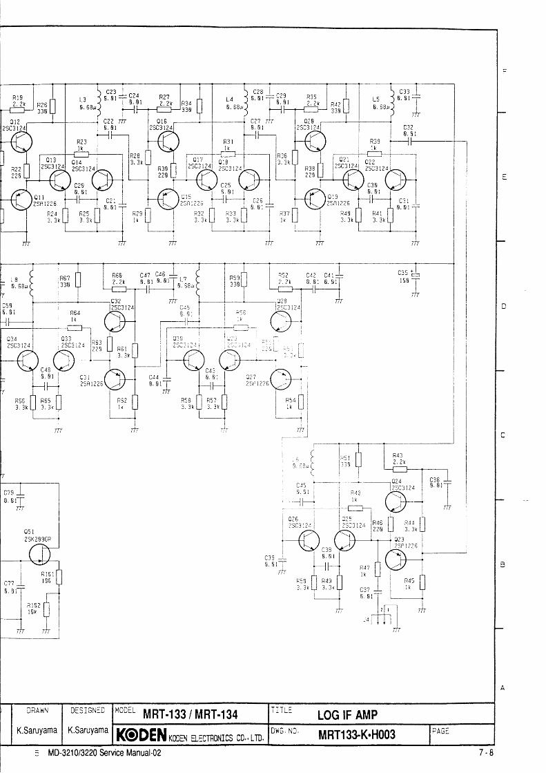
L48 . 6 8 l l
R 3 ll x
n 1 ?) < 4 2 1 ) A
n 1 Q
) c f a 1 ? A
c25n r :
t > n t ( c 6
R ? 43 . 3 k
0 3 42SC3 l 24 ? q n ? t ? t R 5 3
? 7 3
c 4 88 . B I
R 5 53 . 3 k
2 S R i 2 2 6
R663 . 3 k
a ? l) a r 1 ) ) A c??
25C3lZd
l / . ' ) )
B . B I
[ , J f , ;
l 8 B
n 2 a
2 S C 3 i 2 4
0. s l-rI
m
nq , r
2SK2 O 9GR
MODEL MRT.133 / MRT.l34 TiTLE LoG lF AMPDiS i GNID
K.SaruyamaKODEN *ooa B-EcTHoNIcs co., LrD,
Df{G Nc MRT13}K.Hoo3
a?' l2 S n 1 2 2 6
MD-321 013220 Service Manual-02

GND
j ;
i i
-I
IT
C 3
APPROViD
H.Shindo
C h i C K E I
H.ShindcCCNTINTS ADPFOVED

,i
IIiI
I1
II
I
II
l
II
II
IIIIII
Ii
I
II
I
III
Ijf.
I
c
B
DBAI{N
K.Saruyama
DiS i GNED
K.Saruyama
MODIL MRT.I33 / MRT.134 i rL! s coN
KODEN *oon ElEcmoNrcs co., LTD,Df{G ND
MRT133-K.H004 ;nac:7 - 9. MD-321013220 Service Manual-02
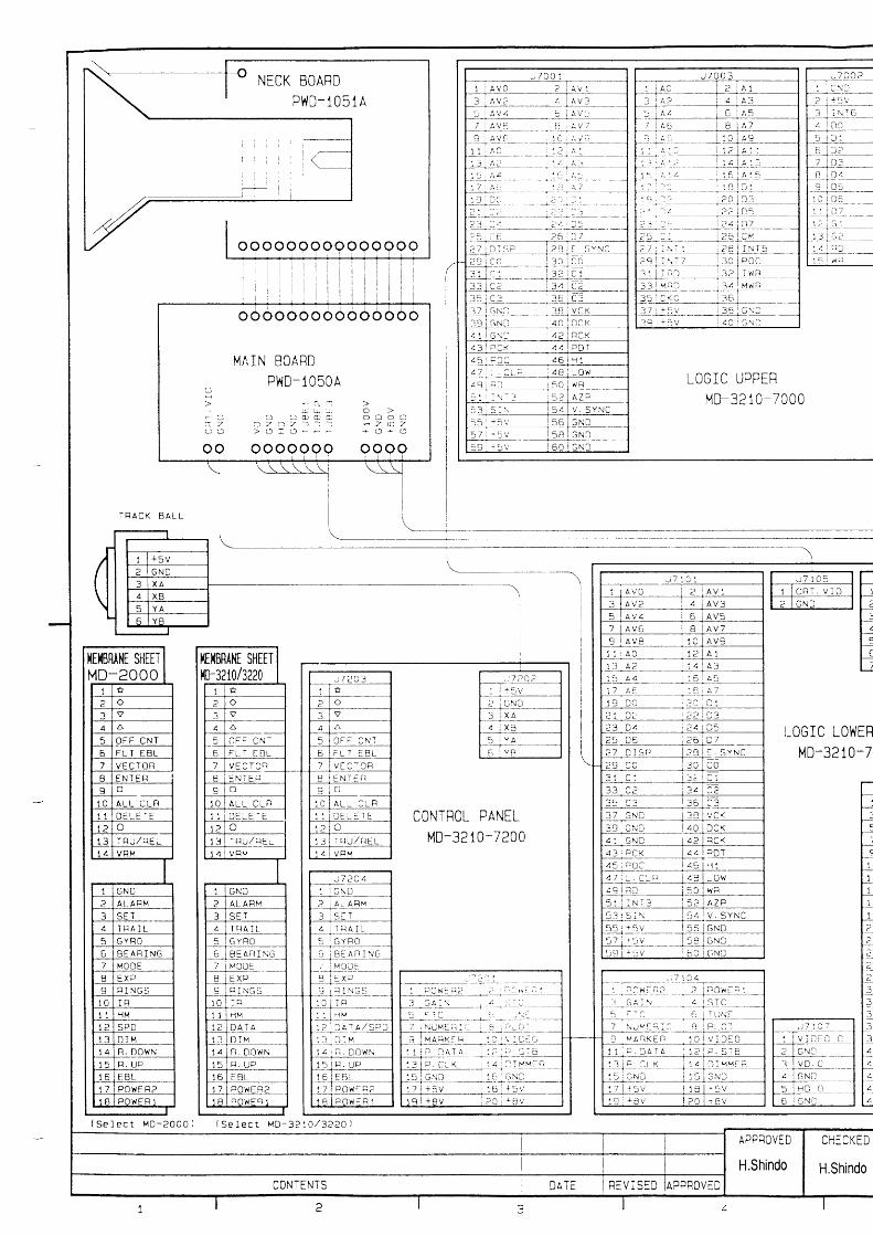
APPROVED
H.Shindo
CHECKED
H.ShindoCONTENTS N A T F F:vI sED lanrnoveo

J 7 1 0 6
100
( s e t e c t M D - 3 2 a o l
J 7 1 4 2
G Y B O I N T E R F A C E K S A _ O 8
---.r__=-.421__
F 3 I M C D H V J
-F=r;l- 0- r u
_ _ _ lt r 2 I M C T O ! )
r-_^-1 T 3l-d \Ah
_ r t l A
I C s I Gi 6 R T N
{: l-.----- *-l
{- ; ls"I ' ' L I
L I N E F I L T E RLF2 15NEWfr--:J\----l
f ' . ' s i l - I ' r s+ I
; r i : ; . r I p ' s -
M D - 3 2 1 0/ / M D - 2 O O O
i 5 A I 1 2 v iB A t 2 4 / 3 ? v
M D - . 1 2 2 C
1 0 a { ? 4 v l
r l ( v a I r )
{G
3 A { M D 3 2 \ A / 2 0 0 A )5 a ( v 3 ' 3 2 2 0 )
. 1 5 4
J - r .8 . J Z Z E F
Q t t 7
M A i N
J ]
1
?- R 2 I IR l I IC O M
G N D
5 S
7
KSA-05-620 0
A Z I P . CS H F . OE X T T R I GT R I G . O 22 | GNt )
3 0 I 3 u Z . 0P M , / T R I G i 3 2 I P C h E F 3
, 1 l P O W E R 2
4 2 | + B v
DRAI iN
K.Saruyama
DESi GNiD
K.Saruyama
M.DEL MRD-62 / MRD-68 TiTLE DrspLAy uNtT tNTERcoNNEcTtoN DTAGRAM
KODEN *oon B-EcTFoNrcs co., Lm.D''G No MD321o-J.Eool
t - * l t n ll _1 ,_ tz . ' - : ' I J : * \ - l ' - : . JL a + ! : ' . - - - - l l : \ r : L : - iI = i , ' - ' r : . 1 I . . _ " - _ l : t : _ _ ll _ _ i _ i _ : r ; c I I z : L : _ _ l[ : l v : r : c ' ' : l [ ] . - a r G 3 _ ll 6.Eiov l l r* ;1; i _11 7 G \ t l r
t " II : ' A . z l L I
PO|^IER SUPPLYMD-3220/:OaO-0oOO
( S e I e c t M D - 3 2 2 0 I
MD-32 t0/3010-6000l S e l e c t M 3 - 2 C O C / 3 2 1 0 )
J 5 0 0 61 I G N D
-? l l ac t i . ;I I r 1 2 v- l
< jc r ' ro__5 : v 0 r o p +c
7 M 0 T O q -
sIu|lt tri f t L M a u . s
p s l M l )
T u N f . t r | 1 2M O T O R . O N
J 6 0 0 9
J 6 0 0 7
a i + t 2 v
5 l p v l t R I O
?v /=
L INE F ILTEFMD-32 10-6 100
l l l f l . 's* I
MD-321 0/3220 Service Manual-02 7 - 1 0

o(.clr.Ll
c.)
{ x{ 5 .
a O
=
L >o
o u . )
o as l o
r 1 -(-)U1
c-)
- t X< >
a O
=
: . >o
o t r r
oz.a
J
4 F =z . = d .- c L o< = 2 .= -(-) -to <\r
SCALE
o(o-)
CHECKED BY
H.ShindoTYPE
MRD.62 / MRD.68TITLE
LINE FILTER MD.3210-61OOMlDRAWN BY
K.Saruyama
I(ODENES:ffiNICS MRD62-K.HOO27 - 1 1MD-321 013220 Service Manual-02

MD-321 0/3220 Servic€ Manual{z
7. DIAGRAMS
ANTENNA UNIT
E122
'. utAutlAMU I7.1 Circuit Diagraml
Bold letters (for example VIOLET) : The thicker wirePlain letters (for example vtolrr) : The thinner wire
scArF---]
GND BLUEMAG (H} GREEN+12V RED
4 GND BLACKMOTOR + BROWN
7 MOTOR - VIOLETI9 TUNE. R W-RED10 M O D . S PINKJ6004
VIDEO.G SHIELDVIDEO CXGRAY
2 PS (Mr) W.GREENPS (L) GRAYt n tu . t t SHIELDTRIG BROWN
7 PS (M2) YELLOW .8
MIP GREENJ60051 GND VIOLET
Jt'lt- WHITETUNE. O ORANGE
4 TUNE. M RED
CHECXEDBY
H. ShindowpE
MD-3210iMD.3220TITI,E
TNTERCoNNECTToN DTAGRAM (ANTENNA.D|SPLAYI
K. Saruyama
I@DENErE(TroNrcsDr,\rG. I'lo.
MD-3210-E.H001

--t
A 0 - 1 9
TOCYRO I /F
D I SPLAYU N I TM R D _ 6 2 L I N E
F ILTEl,l0-3 ?- 6 1 0 01F.21
MA0- 19
KEYDECODER
E8LVRM
CONTROL
EBLvRll
LAMP
CRT 8R ILL
TUNEG A I N51CFTC
MD-3210- 7 2 0 0
L S I
KCD-24
0cPOITERSUPPLY
rtrD-3210-6000
L o G t c L 0 9 E R M D - 3 2 1 0 - 7 1 0 0

D.Y
L O G I CUPPE RMD-3210-?000
t0GI F
AMP
I r r q a n N l
GYRo r /F KSA-08
ANTENNA UNIT MRT-133
i o . c
CRT DR IVE BOARD
SLOTTED ARRAY ANTENNAMRA.37
V I D E OM I X E R
L EVELc0 tR0L
ROTARYCOUPLER
D I O D EL I M I T E RNJS69?8
0R NJS6930
RF AMPM I X E R
NJTI946
DRAWN BY
TYPE
MD-3210T I T L E
GENEBAL BLOCK DIAGBAM
KODENETEqRoNT(sowc. No.
MD.3210-1.H001
IN
MD-321 0/3220 Service Manual.oz 7 -2

TOGYRO I /F
D I SPLAYU N I IMRD- 6E L I N E
F ILTEMD.32- 6 1 0 0L F _ 2 I
MA0- l9
0 r v r / E1 1 2
EXT
KEYDECODER
E8LVRM
CONTROLccT
E8LVRM
LAMP
CRT BRILL
IUNEG A I NsTcFTC
L.tD-3210- 7 2 0 0
L S I
KCD- 2 4
DCPO|llERSUPPLY
MD-3210-6000
L o G t c L o W E R M 0 - 3 2 1 0 - 7 1 0 0
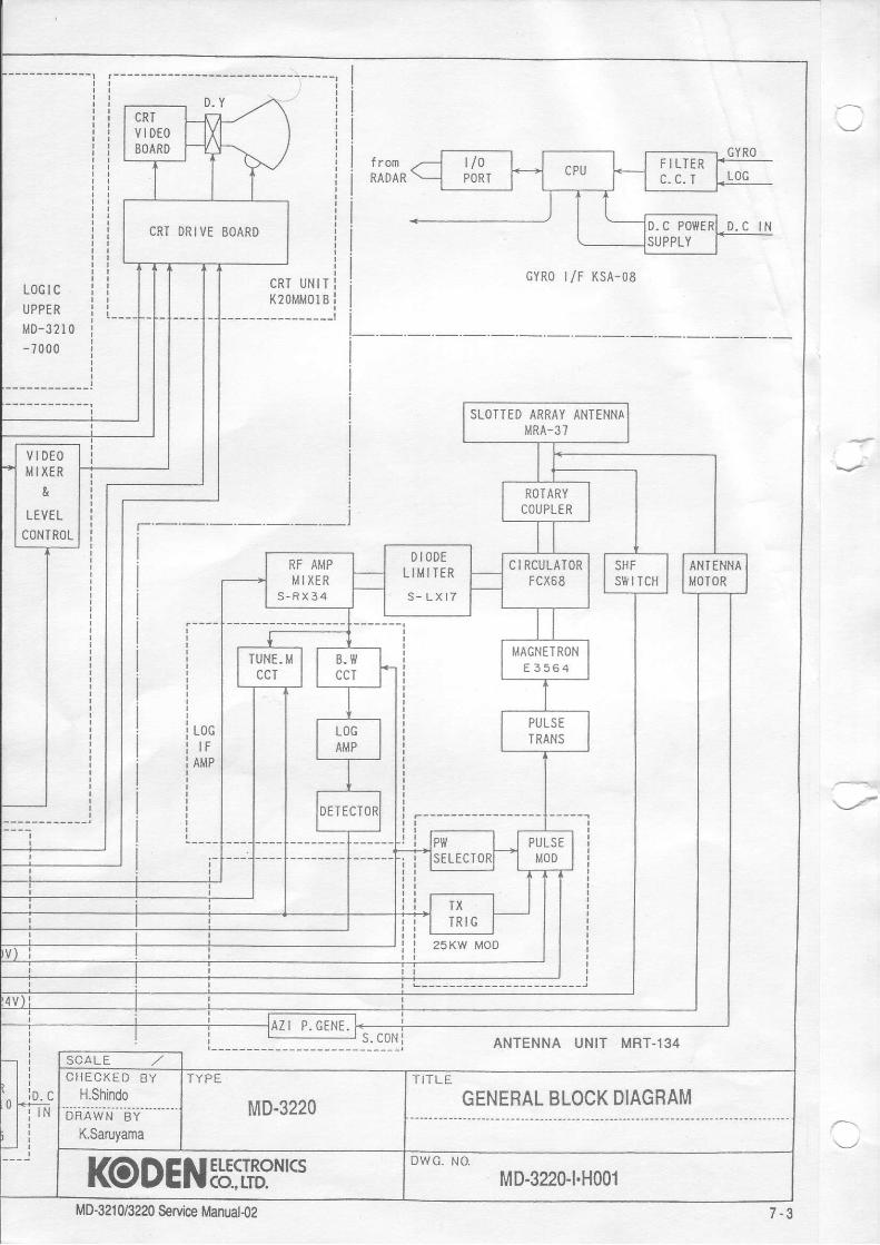
I
l romRAOAR
GYRO
GYR0 t /F KSA-08L O G I CUPPERMD-3210- 7000
LOGI F
AMP
ANTENNA UNIT MRT-134
io. c
v0POR] CPU F ILTER
LOG
tD.C POIYERSUPPLY
D , C I N
s. coN
CRT UN ITK2OMMOI B
CRI DRIVE EOARD
SLOTTED ARRAY ANTENNAMRA-37
V I D E Otil IXER
&
TEVELCONTROL
O I O D ET I M I I E R
s - L X t T
T Y P E
MD-3220TITLE
GENEBAL BLOCK DIAGRAM
l(oDENELECTRoNT(S MD-3220-1.H001MD-3210/3?20 S€ruice fttanuat.o2 7 - 3

CIRCUULRTORU4 FCX68O} NJC3S8 LCL IHI TERu5 NJS6928or NJS6930
TOFNTENM
]OKH TYPEf15Fl4258
AJLS€ TRRNST ]
2 4 T l 2 2 0 9 8
0l 0zHVR-3Hz HVR-3H2
TR IJN]TU? F€N
U3NJT IS!6
Fz
5ap
J r l | | |
LdG IF RI1PPC8 UI239U52s 1?
.J,n-lTfl
Jl Hdo. Pc8---1 r l'2-i ioxt rrptl is
23sus22368
- J 3eC
eg33J r f r ;
5 CON PCB J?
v9",,.""., ,Fi l' E
J I, ,Fl l, 'E
I H HOTOR I-)I OJ* rJoToR {+)I OJxg AzruusrH
t i l*; i ibl H f i o o . sI Gl+ aNDI H PrrS {Ul)I oJ; P/s [)I o1; [aG {H)l f f iG f lDI o-h; cArtlI o+: slcI c F + + r u E BI c++ P/s {uzlI CFt- IEIGI o l i c N DI G]+ +lzvI o*l: ruNEI * I , IEIEBI o-l+- vlDEoI olt o tto
rrr-T't1 3 t I I I I
t{4SIIF I{8RNEsS
HR6NFT34543482
ANTENNA UNIT
l@DEN[b:S,** DtrG. r{o.
MRTl33-K.H001MD-321 0/3220 Seruice Manuat{2

{- . lF rc8 roror,F-i '
iir<w TYPE r.t I )'1-.
l i ! 2 2 9 U 2 5 3 6 1}t- = ,.--r
egg! rnrf;f i s 8 6 L - -
rliffi-rf L 1
CHA'IGINGD cHoKE
- l la-r-----------titr'l-\ I-'1 * l'
zr\-/
PLTSE TFNNST I
Fz
5a
s c.lr PcB Jz99o, , . , " . , 'F
: l,,tJ I' 'F
t l" t
EII oii roron r-rl?ti|lolona.iI e-f{- AzlluslraI qfi s8rI u-1; GxoI o-fi xoo. sIq-i ictrD| f f iP / s t l lI q=P,s [)I oJ# AG {Hl1ff i f f{oI qji GArrlI q* slcI Gl+ ruilE II o-{+ Pis {uaI cF+- tRlG| ++:-e rol # + l z vI c>.{: luilEI OF{+ r. IErEBlo_Fv rDEolcFFGt {D
eea
J 3 l I I | |
J r l I l l
LO6 IF NHPPC8 UI239U52512
r t t l t l I
WPE
MRT.I34 ANTENNA UNIT
ETECTRONICS@-trD.
o$G. t0.
MRTl34-K.H001MD-321 0/3220 &rvics Manud4z

R541
0. I
@
c r 333000p
c r 2
E4
E3
MOD. OUT
GND
MAG (H)
PC8:222U238?5X2 sFEFgaElE l d
c l8 .II2
c3 91 -1 .5 - tB
0 r 2st1- 1. 5- I
0?
]n -T_
ITN
,'T
c r 633000P
I Fc l533000P
I Fc t 433000r
EIr_OIm
MoD (10kw)MRT.l33
DUG. ito,
MRTl33-K.H002EUCIrcNKS@.,rTD.
MD-32 I 0/3220 Service lianuat{z

I
ArT, CCflnOt+lzv {wrol
R30568/llr
014zSCt8l5
!Lc2T I B+
E6
rs(l)rso
! i -r .s-,0? Gtrll|o.sP 6 0ffi flaP6 {r)|rrc dlc{DINF]12VGl lD
+12Y+12vGiID
052SC?98 r
T'A CT€tD
mgEs,h
0 r 0SHISJI?U
c ? l' ' !B I

s.o
02lslt \
0 llsl588 fa
03rsl588
588[-l*.- r
r r r s r r s 2 .5 r ' L6 3 .5T L? 3 .57I
L! -2:-5T I
R23lll
R2tl n
n
a
c lB8. 033: c l t
0. 04?
R2I,1
n2l I
0. 033R2Zl11 c2n
R I 8 R I ?ll1 ltl
'; i; * S:*:..* *".. - +*"i+ #'i1,,* *,,,o h i r L l 0 n 1 1 8. B,r? 0.8.{? 0 ,04? 0 . 8 4 ?
Rr9F1 r)
L l(" l l: l i112
'A C23 -Ln?r' | | |= l T o . o r l w l - - -
I I r l ? - : L t . rI aY_Y-11 | u. lt t t l
m l z l r I
Rr3l r
?ib I |lil:,,"l 8 k I
\h
|tm{c| ns(]i Gfs)
DFAI{N
K.Saruyama
OES]GNED
K.Saruyama
MoDEL MRT-I94 TITLE MoD (2skw)KODENxmaE$rno,rcs*,,rm.lo'u'o' MBT13&K.H002 IPAG:
5 M0.3210/3220 Seruica Manud{z
F

_-.l
lTT. CC{no[+lzv {olnl
m0560./lx
0t, lzSCl8 t5
c? 1Lc3
T'' T'nrlT rff
rs(r)16(o|
+12V+12VGil0
^" E6i i -r .s-ro9 I ' i i l
lg).IPB (n)P6 oraPA (IJ116 0ie|Dna| l2 l lGIID
052SC290 t
ltac. cTGI{D
@
?"m
ihrozo $,.r-,u
0 t0SH I6J I ZU
-A93-r '- c8l l 8?-----1UI
tf
c5 R5l. I 4'1

^TL CCMnCt{oflro0
R30560./ lll
0 1 4zSCl8l5
tl_c2T'uI
mE6
$ ( l lt6{q
i i r - r . s -n9 Gv l
ucD.8P6 0rt16 flaP6 {r}raro {he|0mn+t2VeN0
zsnl02o ;;-t. s_1s
010SHI6J I ?U

oo
03lsr588
l lI 1-1rc I
0 lrsl:
I
i88 l-l *'lsl58s --Ln- r +
t fI
L6 3 .5T L? 3 .57L3 2.57
R25lt't
L4 3 .57 L5 2 ,5 I
R20lf,lR23
lll
n
a
E|
c1 !0. 033: c l l
0. 81?
F?l f lr f l l l n z all1 crc r l c20
R2lll
033
IR l 8 R l ? |l H I l
' iji -L Ii.o:: I 'L l--r-- -
T T c r s T T c r s c r ?I I n nr t L l [ -033 n nr t
0.04?c l80.8.4?
,01?czl
0 .04?czz0. 81?
R t 9It1 J)
L l (" l l: l i1123T
+!" +Y;,|^J l^^.| | r r ? - L L . )
f - - , " " ' ) - ' - 1o tm 1 2 l r I
Rr3l k
liiry' I lJ[]:,,"r r -.*A 9zs'* I '
lrrco rU600 do s[}
DRA}TN
K.Saruyama
OESIGNED
K.Saruyama
MoDEL MRT-I34 I l I L E MoD (25kW)
KODEN xmrx EffrnoilIcs co., LID.onu'o MRT13+K.H002 IPAGEn MD-3210/3220 Service Manual{2
F

VIDEOI. IFIENTIIIE+12VTBIEswTUNE. E
100
Ctlt 00
TE I
0 4 1zSC2859
R?O
9:: q!8I I
R?JA'I
! l -T
tTr;tlc?6e - 0
J6
R?500
c70
CHECKEI
H.Shindc
tonlNt i. io
R ? I228
R8?t. ' tk
c69
0.0rTnf
0{9
R9633
PCEi 2321J525l3X{
0 . 0 7m
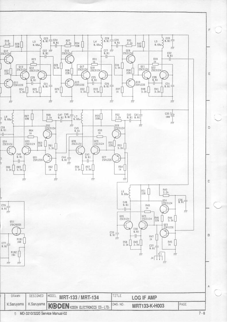
c2 l0 . 8 l
0312SAr2?6
R.{03 . 3 1
a2!3 .3k
0 . 0 1 0 . 0 :R522.2r
c1? ul
o .o rTm
R503. 3r
R17I t
c3?8 . 8
3j3,ti,ti",----l0 . B t
c?9 IB.0rT
m
MOOEL MRT.I33 / MRT.134 TiTLE LoG lF AlrP
KODEN xma, E$nolllcs co., LrD.Dr{6' No MRTl3}K.Hoo35 MD-3210/3220 Service Manual{2 7 - 8

B . I T/n
8 . 1 - Tfn
X i t e A
xoToR t*tIOIof, l+)l2lttETfi
st{Fo{D
m.sclD
P,s 0r0PA OI
[rc t$ct{0GTI{$c
TltlE BP6 fia
tnEe{Dllal
TI'IEI L€tER
u0s)e{0

J U l f - - S a n / o ' s r n o r o r
6 P E N - - h a l o b a s n o r o r
c l00. 02?
LO
r{!-ojr
uooeL yp1-133 / MRT-134 TITLE s coN
KODEN rmal ErcTBoNIcs co., Ln,5 MD-3210/3220 ServilE
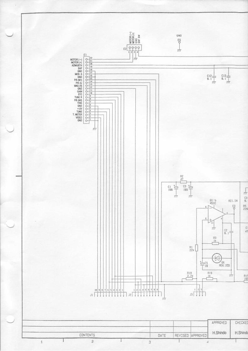
", \)oel0 R06;2EB
voron (-txomn l+lla||tFTtl
sfiFe{D
rco. se|0
PA 0r0P6 tll
flrG fi)eloGtflsTc
IIXE RPA ora
TnbgiD+lWm{E
T. IIIRvI0€oot0
Jt lP - - San ro ' r hotor
oPEN - - t laroba's noror
cr80 . 8
MOOEL MRT.133/ MRT.I34 TITLE s coN
KODEI{ rma a$no.rrcs co., LiD.ou' No MRTl3&K.Hoo45 MD-3210/3220 SeMce 7 - 0

J 7 0 0?
3 A 2 A 35 6
A 6 BI A 8 1 0
A 1 0 7 21 l A 1 2 a 1 3t 5 1 6
D O 1 8 o 11 9 o 2 2o o l2 i D 1 2 ? o5? 3 0 6 a 7
CM2 7 I N T 1 2 A I N T 52 9 I N T 7 30 POC3 1 I R D 3 23 3 M N D 3 43 5 cKo 363 7 + 5 V a,No3 9 + 5 V G N O
I0$RllG sl|rErMD-2000
MAIN BOARDDWn-1n5nA
a z a z ) ) i n z n z
IEIIIIRAIIE SHEEIm{104220
CONTFOL PANELMD-3210-7200
LOGIC UPPERMD-3210-7000
Er:H
E
LOGIC LOWERMD-3210-7
I s e l e c t M o - 2 0 0 0 1 { s e l e c t M o - 3 2 1 0 / 3 e 2 0 )

GYRO INTEtrFACE KSA_O8
-:
I S e l e c t M O - 3 2 ? 0 l
1 A I 1 2 - 3 2 V 1
GYtrO
F3 t MOO HVi
F 2 I M O T O F )
0 . 3 a ( M 0 3 2 1 0 . / 2 0 0 0 10 . 5 a t M 0 3 2 ? o I
1 3 . 1 5 4
DATA
Q s re|5] RTN
D S 1BUZZEF
PM/E . BUZ
M A I N
MD- 3210/vo-?aoo
t 5 A | 1 ? V le A l 2 4 / 3 2 v
MD-32?O1 0 a t ? { v l
F t { M A I N )
KSA-05-7000
KSA-05-6200
T 8 11 S 12 3 23 S 3
5 F26 coM7 GNOa L O G 19 LOG2t o L O G 3
oG4
J 6 0 0 4
2 V I O E OP S I M lP S I L )
5 I F ] G . G6 T F I G7 P S I M 2
e
PO}IER SUPPLYMD-3220/3020-6000
I 5 € l e c t M O - 3 2 2 0 1
MD-3210,/3010-6000l s e l e c t M o - ? o o o / 3 z 1 0 )
J5006G N OM A G ( H
3 + 1 2 VGND
5 MOTOF+6
M O T O F _a9
1 0 H O O . S
LINE FILTERLF21SNEI{t"Tffi-]
LINE FILTERMD-3210-6100
M'DEL MBD.62 / MRD.6B TITLE DrspLAy uNrT TNTERCoNNECTToN DTAGRAM
K@DEN xma BrcrnoNlcs co., L.'o.. MD"3210/3220 Servi@ Manual{2 7 - 1 0

o
rl.|
r x
=
L >
J "
. r x
: t >o :
.. e-g-i,J
v r t _ == > e .- o _ 0< , = == -< J aa .\.
CIECXED BY
H.ShindoTYPE
MRD.62 / MRD.68 LINE FILTER MD.321O.61()()Ml
K.Saruyama
I@DENETECT'RoN|(SDtvG ip.
MRD62.K.HOO27 -11MD-3210/3220 Servbe luanual{2

r o I € : o P o U E R
@ l o c t t - t a v
@ oc to - . rov
1 0 0 0 r
@X A D J
5 0 v t 5E I
E2
I OL I } I EF I I - I E
D 4 6I IDF4
l l ' I c r IE 3
J600r 6d{ BUZ.OI '
J60ro o(E .BUZ. | )
I Jii^lJ6OOr(9)lPowER3t
J 6 0 o l @(P0urEf f ,2
tTf lEal
c l 2
J 6 o o r @
I R F P I S O I 4
0 . 2 2 t ' "l 00v I - 6
05. - - . .2SCl8r5Y
2 S C l 8 l 5 Yl 0 ( 2 5 1 1 9 1 5 Y
@
0 1 22S87720
l l l o i
fj lo,uozsr ri isvl l F t o z
R t 6 R l 7
2 S C l 8 l 5 Y
l r ( I l o K2 l c ln D
T ' - '
C 2
F
=E l {
t - D cv n 0 c E 2 -
5 i . , Y I P I
0 . 0 0 1 r 3 . 3 K
R 2 51 . 7 t
Q ? 8P C 8 l 7
n i i o I l 20 2 6 € 8 2l s 2 0 7 6 A
C l 0 r r 0 . l r
2 S A t 0 l 5 Y
0 2 5 n 3 7R 0 3 . 9 t 7 0
0 l i2 S C l 8 r 5 Y
?l1o'uo l; l
3 9 1 0 . 0 l r
-v- R P-U S- t2 U
( P O r , l E R , I
l l
K C T - 2 | r { M D - 3 2 1 O 1 8 7 3KC T-228rMD-3220) 33 C42
r t l t , 0 . 0 1
- l lc { 30 . 0 t
D Is 8 5 0 - I
[ 7 43 3I tr,
-+Ef+
l l D f a t 2
l o D f E r a

1 6 0 0 r @ @( l 8 V )
19!4 KsL-151
J6oo l ( ] )( P H l 0 i l )
J6oo7 o(Plr l )
J 6 o o 7 @(Pfr?)J 6 o o r @ @( r 5 v ) @ @ )
J 6 0 0 r @ @J 6 o o 6 @J6007 o( 2V)J5oo9 @J 6 o o 6 @
I p 3 - ( - l ? v )
J6oo3 o( r t 0 0 v )
l5 ! " E) F3-o.JA: MD.32ro/ 3otoMD-20004000
KCL-r62
KCL- t65
KC L-16c
R 4 3I (2U
T
r c t 9c I 7-l-0 . I r T
ml 0 0 r2 5 V
D ?s B 5 0 - 1 8
c t 81000, r
?5V
r c 2 {
L I8 0 . 8 . l l
l 0 0 r2 5 V
R15 5.6 2t l ,
' _ l l (lv Apsl 3
c 2 3o . l r
I P 5
c 2 0! 0 0 0 r
2 5 V
t 22 . 2 . H
l 0 0 rl 6 0 vI 2
L 7l 0 0 r I
R t {5 1 02l!
R83 220
32 PC8r7
I
v t 3 254l 0 l 5 Y r 2 8 Z 5 C l
c 2 9
M0-3050
El F3-O5A ' MO 322O/3O2o5t t (l0J
5l t(I ttl
I . rTzsovth
0 2 8X R 5 l1 . 7 r
PcsrT/J
26? s 8 7 7 2 0
J6oo3 o( r50v)1 6 0 0 r @ @( r 3 5 v )
J 6 o o 6 @(r{00 .s )
J 6 o o l @(r{0I0R.0 l r )
7 1n 7 02.2K 4 7 0 (
I lrJ
l0K '---:14
fFrzv- lnooR 6 42 . 2 '
Q 2 {2 5 C l E l 5 Y
f l662 . 2 t
K I
1 t 2 Q
n6s220
D 4 lI l 0 F 1
c 2 R - l I l 7 P- v - n P - u s - l ? v
r6oo6 oI P 7 ( E ) ( X 0 I 0 n , 1 )
J6o o6 o(H0roi : -)
G 2 R - u l 7 P- v - n P - u s - l 2 v
l t A l 7 8 l 2
r P C 3 l 7 l l
r P C 7 9 , l l 2
c ? 6 c 2 1
R s O f i 5 2 . 1 . . 5 K
0 1 2 I l D F a
1 0 0 c 1 0 . . l 0 v2 5 A t 0 l 5 Y
T,i''l,l;i-m mI KCL- t6O (M0-32tol
KCL-r67 (MD-3220) R60 4 - .7 [ 1
i L4 L5 KCL-1630 . 8 r t l 5 0 r l l
022l( 5!rr3 2SBlo22
n 7 9 R 7 6 R 7 8
doll;1ill"g
R 5 9
5lr,
D 3s 8 t 6 0 - t 8
r s 2 0 7 6 A
DRAWN BY
TYPEMRD.63 / MRD.7OMRD.62 / MRD.68
T I T L E
POWER SUPPLY MD.321 0/3220-6000M2.1/2
EI.ECTRONI(Sco..[ID. MRD62.K.H001.A1/2
s t - 3 5 2 2 V
(NAG ftO )+ J6ool (D)TP6(G)o {H .C i : ^
I J6ool (9(r)t- rcxol6)Grt
rsoor o@
MD-321 0/3220 SeMce Manud{z
2 0 . IT 3 , l 5 A
7 -12

z
oo@
z
=z, z =
z,
z
z,
=z.
(5
= z
z.
=z,
z, = zo
= =
z
=z
z,
=
z,
z, ao
z, zIJ
z z
=..;z.
I
z,
z, z(, z,dt
3L
=
z,
=z
= =z
z
== = z z z,
zqr
MRD.62 / MRD€8 POWER SUPPLY MD.321 G6MOM2.Z2
0t tG. t\o.
MBD62.K.H001.AZ2I@DEN[b::Ito?**
I
7 - 1 4MD-321 0/3220 Seruice Manual{2
=z,
F.J
c,
Fz.
z,
z
o(o
r-----f---T--l
l - l . l l l lt : E t o t t > t I
tztdtzttl'tz.lI l + l ( , l + l o l-f-rFr-lt9 l - tc " t< - r lq ll . - l l l l l
.2,
z,
=z = = =
z,
z,
z,
(J
J
(o
Ez, z, z
I
=z,
=
z,
=z
z.
=
z,
F.l
z,
zJ
z. z. z.
=
zz.
= z z z z z(,
qNf(D
E
;oIL
=I
z,
z,= =
z z,
z.
-
PoWER SUPPLY MD.3210€000M3.22MRD.62 / MRD.68
DWG. tlo.
MRD62.K.H001.BZ2I((DDENErE(TroNKsMD-321 0/3220 Service lianual{2

v- la '
,oc
c t 0
r r l a
x 8 ! 7 7 l
7I
. ct !. c
- 1 0 - 3 1 9
r c r t 2r cL I
rrrP6 aur Eitrrt t !uf i /r
0 l
0 5
! ?0 r
5 ^ r 9s l l 3
/ i ^o r r
I
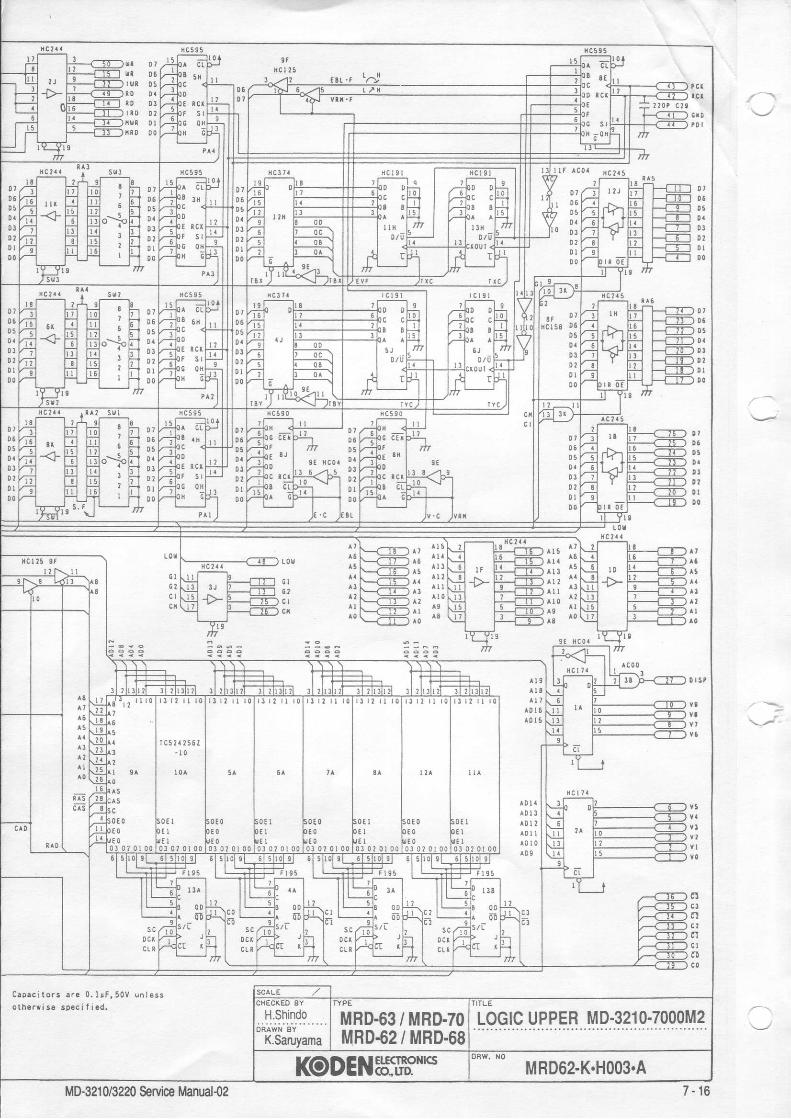
t 0 0 3
rcr 25
D6
1 0 6
D1
0 5
0 tD 'DI
o 1D5
! lD I
0 l
0 5
o D !
0 l
! l! lD ID O
a l
c l
G I
a t
^ 1 r r rf l ^n
f l ^ ro
^ ' s l lr r r ^ !
i i i i i
r!
a
C a p a c i t o r s a . € 0 . 1 r t , 5 0 v u r l e 5 so t h e r r i s e s D e c i t j e d .
01/--;1 li.';1 l,;1 . li-t o?06 z;7l . _ _ T:t fi] ' t?'t 05Drr? 't tiil T,t " ti_t !5Dr rii _\r T;1 r,;1^r-<.1;-l D.Dt V'it f';1 h;1 ' 1,1 DrDzV;t fn nn ' E_l 02ot v-;t fi;_l l,? I r5 0 |00V-t f-L-l--l ' f-l oo
D70 5
6
32
0 1
0 5
0 10 ?0 lDO
t
I7I
a 3 r 2 r l r 0r 1 r u u r o r 3 r 2 l l r 0
LOGIC UPPER MD.321O.7OOOM2H.Shindo6;;\ii, sV " '
K.SaruyamaMRD-63 / MRD.7()MRD{2 / MRD.68
MD-321 0/3220 Seflice ilanual{z 7 - 1 6

t r l 6r r l t
l .
L ?t lE hc0 , .
BL
l t
l l .
uPDTo?0tct- 1 0 - t t 9
I
t t . t . , , ^ot

r D D 3r R 0 0 ?
N C I ? 5
0 5D '
DJ0 ?D I
D5
0 l0 0
0 5
0 l0 0
D5
D ]
0 l
0 10 5
0 10 2
00
0 t0 50s
0 tD I0 0
0 7
o 70 l00
G I
^ r 5 i ll l {
^ :
^ r3 l i^ r I f :^ r o i :
D 50 5
! lD I0 0
C a p a c i t o r s a r . 0 . l r f , 5 0 v u n l e 5 s
o l b e r r i s € s p e c i l i . d .
al
0 6
0 l
0 lDO
r r sc^3
t ? t 0 r t r l r l I r l r ? l l r 0 r t l 2 [ |
MRD.63 / MRD.7OMRD€2 / MRD.68
LOGIC UPPER MD-321O.7()OOM2
KODEI{bffi".'MD-32108220 SsMce Manual{2 7 - 1 6

x 8 ! r 7 I
r t 5
t r l a
r i \ - - - - -J J . ' v ' i i
l l C - J r t o? l l
l i c- ,r tor j1
- l o - 3 0 9
r r rP6 ou r i i
h c 3 t t ^ c t 1 9
' ! : . , , f l l

0 5D '0 30 t
c t
0 l0 l0 lD q
^ 2
(0t
a la tt l
LOI
a tI t iiiii
^r5 1 lA t a
^ :
r r r 1 1ili lii: i;
D
c 3rl
c l
c 0
C a c . c i t o r s . r . 0 . l e f , 5 0 Y u n l . s rolh!r* i s . ip.c i f i .d.
ot a-;1 r,;1 r,;1 0 h-r Dt05v7-;1 tr;t Ti:] t__l D6051/-?t __: r'n r,-:t o E-l D5D.7;'l _\J- t=1 t;t^--:^E-t 0.otv-;t [n t;I ' t;'t 0Jot v ,-1 l-:1 tiil J E_l 0 rDt v-i\ r,';'l ri:l . li-l DrDO V---'1 r_-Lr_1 . r-t 00
0 70 50 5
D I0 lt t0 o
o l
0s0aD 3D '0 tDO
0 7050 5
D !D2D I!o
r l u
MD.3210-7000M2LOGIC UPPERMRD.63 / MRD.7OMRD.62 / MRD.68
IID.MD"321 0/3220 Servlr Manual{2 7 -17

0 [ 0
tiDo
G I D
H OGI I I
t t TL C L
AG'57D 1D 6
D 4D 3D ID ID O
0 t 5
L S I
a 0 a g1 l
l l t T2 . 2 K
l t 8 4 0 4 s
-c56 A t lssr
R D
R l 2 l 4 0 4 9
0 5 0C 6 , l I
R l 8 5? 5
R I32 5Y X C0, t? ' ? \ ro , .n ' t t
R IR 1 8 32 . ? [
1 5 0 ? rR 1 0 6220 7,106
- r C 150
c l 0 a
f-
GDO
GD?
I R t 6
I , r r r otr RA rL-iA
Elo
x l
| | i T v D D : 9 9 . 1 0 2 , t 0 3 , 1 t lP o c l ] 7 , 1 2 0 , 1 2 5 , l ? 9
v s s : 9 8 , 1 0 1 . 1 0 5 . t 0 71 1 0 , 1 1 4 . 1 1 6 . l ] 9I ? 3 . 1 2 5 . 1 2 8 , t 3 2
| 5 v : s 6 . 5 7 . 5 0 . 1 3 0
0 N D : 3 . 2 9 , 1 9 , 5 1 . 5 57 5 . 7 7 , 1 0 1 . 1 0 9
i i i i . r i i , i i i . i , r
il8, T,_ li:ii193 r r 7 .06
n t S l

C a p a c i t o r s a r s 0 . l r E , 5 0 V u n l e s sother* is6 speci f ied.
i,#i' i lG I D
i l t 5 R t l at 5 0 6 3 R l 3 ? ? 7
l l3'f lA8';<rc'-o' m m
'li't 1',';(vG
c 6 r I r 8 9!- | c58
I
I
B
3 : 3
t:t;t'6 Fnir Iq Exon lr;-." t!!l!!!l
2 . 3 G T D
1 , 3 0 r D
I R O
I R 1
TR?
1 8 3
Tf ,C
MRD.63 / MBD.7OMRD.62 / MBD.68 MD.3210'7100M2 1/3
KODENHIS?*" MRD62-K.H004 A 1/3MD-321 0/3220 Service Manual{2 7 - 1 8

----cE)D|l.lr{ER
T P 2 D l l^ H Z 2 0 - 2
U P P E Rr,__-_-\ rtrnl
P OI]JE R SUPPLY(r-----J J7lo2
PO| l JEN SUPPLYa-J) J 7l 03
PAI IEL( - D . l r t o lc n T v t Df l - ) J7 l05
c R T V . t l( -T ) J7 l06
0 P T t 0 l t(T----] J7lo7
+35V+35V
@v R 1 0 4 8 8
H C l l
n l 1 6I K
R 1 0 04 . 7 ( TUI IE R
TU} IE O
R t 6 8 3 3 K 2
R 9 St 0 0 K
l-i u "i
rlAx 1V R 6 I O K
TUIIE
6 VH C 4 0 1 0 3
frfr3 c t 8 r o ,
frfrc 5 0l0 0 , r
l J P C l 5 5 5
T P 3 R l 0 2I O K
R I O 4I 5 K
I 5 K 0 2 6 C l 8 l 5R I I 4 3 . 3 t ( E X
TR IC\ T I { E T c 5 4
V R 7 5 K
2 V
. r 0 . 0 I r 9 Xh H c o o
v R 8l 0 (
I l x p E L A Y I
R l l 3 1 0 08 1 1 53 . 3 K
H O T O R
P / S L
P,/ S l,{ 2
G I {DP / S i l 1
ON 4 B BH C t 4 @
9 5
ca2 looP 2R.16K
c r 2 3
t 2
R 8 72 . 2 K
2. z f ,
c 3 s t 0 0 P
S S T
I 3 l - r 4 5
R 9 6
Q l 3c l 2 t 3
R 4 7 I O
I 1
+ 1 2 V
H C I ? 3
c 3 81 0 0 0 P3 , 3 ( R 3 t
c{2 t ^ l2v lq 7 8 l l 0 8
1 0 0 r 1 C 4 4 Ic41
clz
frc 6 8 - 7 4 . 7 6 - 8 9 , 9 r - 9 8t 0 0 - 1 0 4 , r 0 6 - 1 2 5 , 1 2 7 - 1 2 9 ,
l 0 KE X T R I G
T R I G
I R I G
T R I GG
PO!JEN IPOIdE R ?
R2I K
+ 8VAc 5 ll 0 0 r + l ? V
I S 7 S N 0 8 r 5 v , }5V
G I { D
R333 3
0 0 c 4 5 2 - 8V '1 C 5 2 ,
l 0 0 rI'frI P 78r {05
l 0 0 rc 7 5 , 9 01 0 5 , 1 2 6I 3 0 , t 4 6
GI iD+ s V A I I6 r
M /01{P0 r !ER IPO!JER 2
zu z . 0
P U T S E I ! I D T t 1 . R L Y C O } I T R O L
R L Y \ P . I I J s , { I t{2 LP , /S H I L n tl HP,/ S l.t 2 L L H HP / S L L L L h
C O N I i E C I O R
Rr032.2K
E X T . T R I G
J 3 / T DJ 2 S P EJ I
TYPEi r n - e t 1 . ' / 1 ^ 1 ^
M D - 2 O O O , / 7 O O OM D - 3 2 2 O , / 3 O 2 OM D - s O 5 0
TITLE
LOGTC LOWER MD.3210-7100M2 2/3
ETECIRONI(S(O.LID.
owc' No MRD62-K.H004 A 2/3
R 3 4I O K , T P
i r r (n l l 0
c ,
MD-321 0/3220 SeMce Manual-0z 7 - 1 9

RA5R A I
R t { 1 0 1 t 0 4 J 3i lu P c 4 5 l + t 2 v
A 7A 6A 5
A 3A 2A }A O
L0rdP 0 c
R Ol|'R
I
)
( 0 0L S( 4 0A t
A 7A6A5
A C l 3 8
8 XA C 0 4
l 0 - z
are 0. l IF, 50V un I esss p e c i f i e d .
D7D6D5D40 30 2D IDO
9 3A5A 4A3A2A IAO
l r (n 9 t
Rl)IrtR
9 2l t (
f r u ,
R S 0l 0 K
U 5It(
n 9 8I ( 2
c 1 0I 0,r
8 1 1Q3
8 7 7
D1
D1D3D2D1DO
D1D6D5D4D3D2D IDO
2 . 2 t ( 1 3 a
+ 1 2I
- r 2 (1---3, G
* 8 V
7 7 2
P li, IPl/,0T t i 3T f l 2T H IT HO
GG
CC
PC|(
t / 2 F7 ? C tTRII,T R CI R 3I R 2l R lT R O
EY8 C 0 4
6 - z
P. CU(P . S I B
P . DATA
PDT
R C (
H C 0 43 x -
I H C 0 41 3 r - -
8 YH C 0 4
9 r.- -
Capac i to rso t h e r w i s e
7 1 0 6 r 24 S
E X PEXP2E X P l€ x P 0
H C 2 4 5 t R A 3
T UBE I --5-T}--*ts lToilrRAsilruaEz ---6'--11 2; ws
rusE3 --7-Tl-------------J
2 1 3
i_<-TT-) DTHHER
I P 2 D l l^ H Z 2 0 - 2
R l 0 04 . 7 K
D 1H Z I 2 C
s | l i
TU}1E R
f l 168 33 t ( 2
T U [ € 0
Fur rE nA l lv n 6 l 0 K
TUIlE
6 VH C 4 0 l 0 3
c41 cqz
c 4 8 c l g
frfrc50l 0 0 r
u P c l 5 5 5
R 9 91 0 0 (
T P 3 R 1 0 2l 0 K
- - r c4 lm
c 5 40 . 0 1 r
@v R 1 0
5 K
9 XH C 0 0
SS T
3 . 3 K R 3 1
(.--T7-)
0 2 6 C t 8 1 5
4 8 8H C 1 4
R l t 61 K
H0I08 0 l {
P / S L
P,/S i l 2
G I IDP /S i l t
4 B BH C l 4
+ 5 V
c 3 2 l 0 0 PR 8 62 . 2 K vn 8
1 0 (
c l 2 3 Fx TELAYI 9 5
R t l 4 3 . 3 (
R I 1 53 . 3 K
R 9 6
R l t 3 1 0 0
E XT R I G
GI ID
PttI R I G
GI ID
T R I G
T R I GG
TR IG0
c i lD
P0tr,E R IP0tr,E R 2
2. 2K
I I
+ I 2 V I R
fr frfr
c 3 8t 0 0 0 P
l 0 KE X T R I G
T R I Gc 6 8 - 7 4 . 7 6 - 8 9 . 9 t - 9 81 0 0 - 1 0 4 , 1 0 6 - 1 2 5 , 1 2 7 - t 2 9 , l 3 l - 1 4 5
78 i l08
c 3 9 1 0 0 Pn 8 72. 2K
H C l 2 3
00rc 7 5 , S 0
R2l (
R 4 8l l (
r l 2 v
c420 0 c44 I
4 30 0I
1 S 7 9 t i 0 8
78 i l 05
-6V r1 C 5 2 I
I 0 0 , r
+8 VAc 5 tl 0 0 x
0 1 3l 2 l 3
+ 5 V
G X 0
,frI P
I
R 4 7 t 0
fitD+ s V A N r6 r
1 0 5 , 1 2 61 3 0 , r 4 6
POI I 'ER IPOI | ,ER2Pt l l0
B U ZBUZ. OH , C ,
P U L S E I J J I D T H . N L Y C O i l I N O L
R L Y \ P , I ! t { l A2P/S t{ I H HP / S 2 L HP,/ S L L L L
v R 5 l 0 K
c 0 | l l r E c I 0 R
U P P E R(---------) J7lol
POt I ]ER SUPPLYa-----l J7lo2
POIl,ER SUPPLY(-T l J7 l03
PAI IEL( - l J7 l04C R T V ! D(T------) J7105C R T V . H(--I) J7r060 P T t 0 t l
(I-----l J7107
+ l 2 v
R34I 0 (
o r r r P 1 2c r 2 1 3
R 1 l 0
TYPE
MRD.63 / MRD:70MRD.62 / MRD.68
TITLE
LOGIC LOWER MD.3210.7100M2 2/3ORAWN BY
I@DENErE(TxoN!(s MRD62-K.HOO4 B 2/3
MD-321 0/3220 SeMce Manual{2
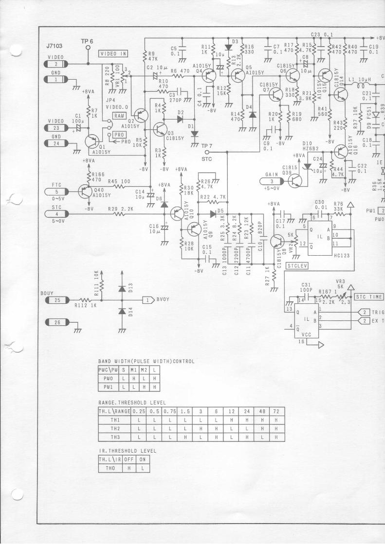
+ 8 VJ7103
V IDEO
R 4 0 c l 94 7 0
T 0 . I
m
L 1GIiD
c 1 8 1 5 YQ 7
l0 tL
R23 . S (
D 1 0HZ6B2
*8.u0 | ,e
|--tID--1f r *ruo
c 1v l D E 0 1 0 0 j ,
* To m
- 8 V
f i 115 r( R 1 8
3 3 0
R 4 15 6 0
j
c
l 0 r HiT'
c 2 l0 . I
l-l 3
7lc 1 80 . I
J
u,l EPrlJ0
R71K
- 8 V
T P 7
sTc
R 2 6
R21K
R 4 322
c 9 - 8 V0 . I
- 8 V
R3IK
+8VAc 1 8 1 5
':_J
^,\-l
4 . 7 K
R 2 2 4 . 7 K
c 1 50 . I
F T C
R 1 6 64 7 0 R 4 b
Q 4 0A 10 15Y
- 8 V
1 0 0
c 1 4l 0 r
2 . 2 K
- 8 V + 8 V A
+8VA
D6
G A I N Q 3
+5 -0v
0 -5v
5 -0v
R 3 0t 8 K
c 3 0- 8 V R 2 9
c l 6l 0 p
BVOY
B A I { D ! J I D T H ( P I J L S E I I J I D T I I ) C O } I T R O L' r0c\Pll jS 1 M2 L
PIIJO L L
Ptr,1 L
r H . L \ r RO F F 0tl
THO L
lTTc- n'tEl
TR IGEX T
R l IR 9 o . 1 l r r \4 7l( IrTc 2 r o t l ̂ ^ , - ^ A l q 1 9
i - n-6, 470
n r R 1 7
; ' r 4 7 0
A 1 0 1 5 Y
A 1 0 t 5 Y
ofFRo lr<__Tio ,[lA l 0 1 5 Y
J L .c 3 , , I27oP m
GIID
+ 8 V A : J X , R 7 6^ . . u . . . v l 3 3 | ( P
= l = l -
:?!+ q- I - I ;
1 '
l g5Q A
' L B
0
I O
1
H C l 2 3: l - l I l 5STCLEV
v R 3A I
l 9 Q P n r e ; r - ' -
L 2 . 2 R ' 2 , 35
l3Q A
I L B
ovcc
22
4
R A I I G E . T H R E S H O L D L E V E T
I H . L \ R A i l G E0 . 2 5 0 . 5 0 . 7 5 3 6 1 2 2 4 4 8 7 2
T H l L L L L L L H
TH2 L L L H L
T fi3 L L ft L n L L
I R . T H R E S H O L D L E V E L

4 7 0R 6 1 < < R 5 3 | ' - -
r . s {> >10K mt l
+ c 2 s I c 2 6 " ;1 0 0 0 P - - r 1 0 0 P d
R62< -dt l :. 3 ( f = l :
< | N - l l : Hl d @ l l d @
- i v h ; l h E 28 . - - l I >DV2
9 l - l o E l s
1t&- *uuol:i: -l:roK f : f : s fsf -F-u6 u- f * I l - l ' - | l - l " l ' - l - l - I : | . 4 L i l 3 5 0
3 9 9 6 ^ , . . | - - - l I ! . m 1 | l m I l l c s z lvcc 8vA | - V -5v t--L-+........... 1 R82l lio/,+ l-iu1 7
2 l l 3 1 2 l l l r 6 DV61
1H360
ca6 iL - 15t o u T | - s v
8 r---{ I > DV77
1H360s v A v R 4 +
c a 3 t I - 1 5
iii--:^T!--l lrHRESH.ttl
011'*j""u' t o u ! l - 6 v
Q 2 4
R 6 8 R 7 1 4 1 0 1 5 YI G r K 1 ( 0 2 R 7 8
3 3 KR 94470R 8 1 > R 6 6 > R 6 7 > R 6 9 > R 7 0
2 . 2 t < 2 7 ( < r 0 0 ( < 1 5 0 ( < 4 7 0 K2 . ^ 1 3 " 1 1 3 . ^ l S ̂ R 6 5
4 . 7 KI I t 4 | t l l t t 8
4 H l | 4 H l | 4 H l | . 4 H
THO
I H I
TH2
TH3
- L C 2 7
T o ' tm F - - l
+ i N l
H C 4 0 5 1 1 H
c 1 8 I 5 Y
c 1 8 1 5
x x > > - o
H C 4 0 5 3 3 H
MRD.63 / MRD.7OMRD.62 / MRD.68 Loclc LoWER MD.321G7100M2 3/3
ETICIRON{ICS(o.,uD. MBD62.K.HOO4 A 33MD-321 0/3220 Service Manual{2 7 -21

POIYE R IPO|{ER2
*oVA0
ENTERVECIORAL LCL RF L T E E LOFFCIRD E L E T E
I R V / R E LVRM
ALARMS E T
T R A I LG Y R D
EEARINGMODE
EXPRINGS
I RHM
DATA/SPO
D I MR. 00ltN
R . U PE8LGND
R4100K
R6l 0 0 K
2 S P4 t P
5 P M
s|l,3PULSE 6
Rl0l 0 0 KRu
c64 7 0 P
J
R 9 ;100K m
c74 7 0 P HC74
J
+5VGNDXAx8YAY8
l tc l4 81 l c 26 G S5 4 24 A l3 4 02 E lI0
cA3 rHC-8-47oKAa
cA6 lHC-8-470KA
'.011# !'u ,100KD - tc8R 5 + \ Y 200Kmc5 410P
2

to*r * t
t G ' o ' u t '.^-'u I iM!.!.9!- I I vnrl-rr 6 |
-1rr H:l i : f f i1' tJl l f f i 'o 'n
TjlFll i i i " 'r- | r,., jifi | yyl#' c', ,h | ,____,___..^- . i l - ' , , , AlJ"-,ol ! l i ; i l f f i " '
ffi 'tiF il l(i),+ |' ..^,',J- '" t>.', | | ,,,W cw I,3r,,,,u00 *l ll i.iilr,r ,*rffiI"'
| | | l^r_+___'........_ cml rHc-a,rroxr
| | I I 'L ^,,,0,,*u.J Il l l " ;g; ' ' **" ' '
I cl ,,,0, I ll l roK l-'t/ ;- i"' Il o , , , o , l l l l , u ; 1 ' * '
I | = : : : : I l l l # - l+" ; - ic13 l -=- , .l ( l I I - - } . , t r o o I l l i u r n x r n l f f i u A R K E R
| | | l l l roK l r ' ; 1 iw-__ ' +c14 " l
I l l l u,p ' ' , ,*oI l l l t o K ) r ' = c l 5
' l
I : : * : ; ; : l ' . i l l ,?, i i f '50vun'sssl l l - #
i - -nr ' ' '^l l '."'I
p.c*)| | /-1-i;-\ ^,rn,.6
| ,!"r", + cz f-@cno
I r#' -m' l'-'t "{i, -ffi:iiI l-*' 'fY ffl;-._*' | -p-l
t._JF::;|
* '' Yo' "'* Tii:,'[L@'auSCALE ./CI IECKED BY
H. ShindoTYPE
MRD.62 / MRD.68TITLE
CONTROL PANEL MD.3210-7200DRAWN 8Y
K. SaruYama
l(oDENELE(TxoNrcsowc. No
MRD62.K.HOOsMD-321 0/3220 Service Manual{2
.*p-
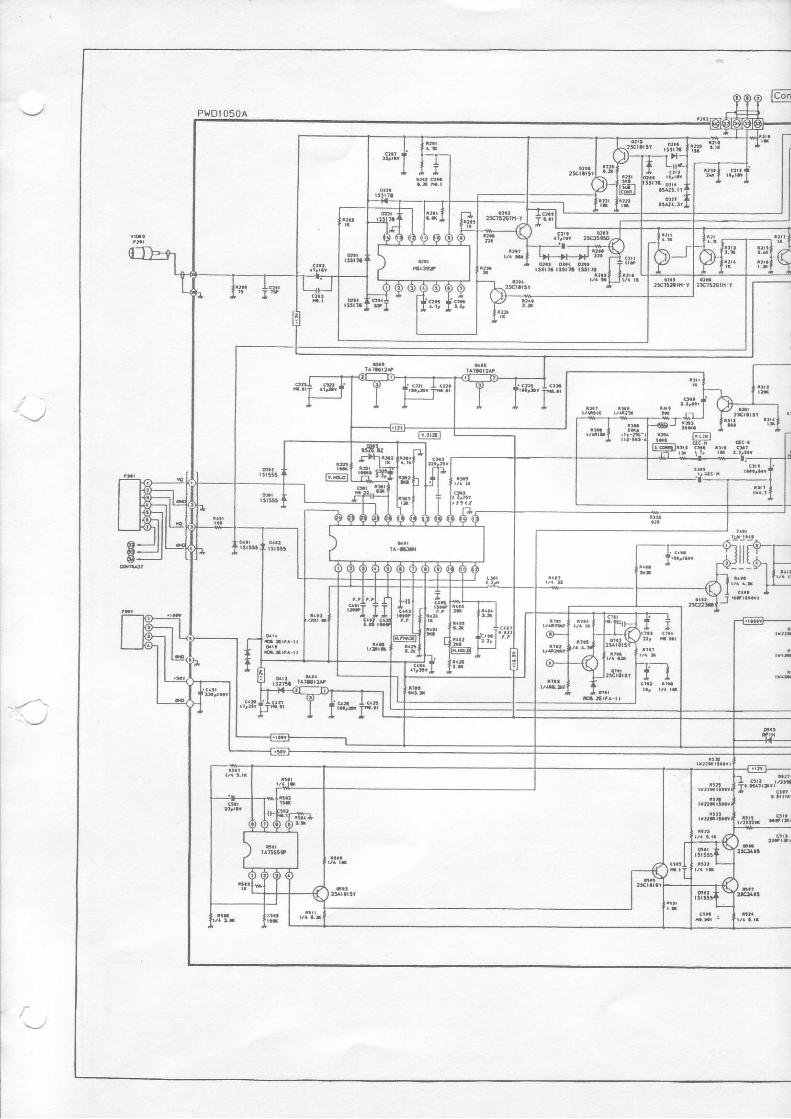

fl[.' 'H'
MRD.62 / MRD.68 CRT UNIT (Kzont'otB)
KODENSTffi*"MD-3210/3220 &rvice Manual{2

.,.J7.2 Drawings for Parts LocationP.C. Board and conesponding serial numberAntenna unit
MD-3210MOD (25kW)
2100251 and after
MD-3220LOG IF AMP
3220251 and after
MD-3210 2100251 and afterMD-3220 3220251 and after
S CON
MD-3210 2100251 and afterMD-3220 3220251 and after
Display unitLINE FILTER
MD-3210 2100251 t02100420 2100421 and after
POWER SUPPLY
MD-3210 2100251 102100618 2100619and atter
LOGIC UPPER
MD-3210 2100251 to 21 00450 2100451 and afterMD-3220 9220251 1o3220265 3220266and after
LOGIC LOWER
MD-3210 2100251 to 21 00450 2100451 and afterMD-3220 3220251 t03220265 3220266and after
CONTROL PANEL
MD-3210 2100251 to 2100420 2100421 and afterMD-3220 32202511o3220265 3220266and after : '
CRT MAIN BOARD
MD-3210 2100251 and afterMD-3220 9220251 and after
CRT NECK BOABD
MD-3210 2100251 and after
MD-3210/MD-3220 Service Manual-02 7 -24

r
MOD (1()kw) 239U5223681..
I
MD-3210/MD-3220 Service Manual-o2

MOD(25kW) 229U25361
( tN---/
l-l rt - i E
t(
6t
, o (E =El o- l
\
{ . It ' s
t .l o (
I
3L
r\nO
z9 t r6Rq3E=
Rf;3( (
a =
\ \
l pE 9
- l lr n ' I
nT
) aFI \ .-- oc rnt r
re , "l )E-.{"'-f, "i':qo
+ rn2c1 rRrc.\ tO3\ -
l .
? 1\
(I
a L
/ t+Ola -RS1 /LO21
N Ll l u 't l
L l 2
"*\JFr\'*\J/'{o13\o F
t-,, E9
+ /-Ba -\ - i2-\) .Fr \ l fac rnrr
V-\ "F 1BtY"o+\-/ 1. / 7-ns a
p\ /-nr5-------1
- c5
l+\-./ \ / rR6\ffi6.0
q rno -r
o
t
Jl ( I coN)(FAN)
' l lJ 3
J 2(t|o cT]
, - aoMD€21 0/M03220 SeMce Manual-oz
LOG IF AMP 239U52512
@r&o@ @
E6 rJS TEH.-F'*IEE - Hn u ---n E 'Uso lgr|-=rsG'
-q-rrdr ls
ID@I E]
J:l:;g eRPrlh'H"*E*'g ffiu"
Id E trIgIEg U "
|6l r_--]-
IR BL l - "19- tF tst
o u
E B E m B B2 f , 2 U 5 2 5 1 3 Y t
7 -27MD-321 0/MD-3220 Seruice Manuat-o2

\
s coN 239Us2352
MD-321 0/MD.3220 Seruice Manual-o2
S CON
22
E Z
o l-'|
I '
o'n
AZI.OUT n.aA v 1 4
$A- utoe # o .
R15 (J -r
6\ .3 R13t a
j- --al\AF
R7C9 -F dryi
--AlV!- :jA/\ l:
+R6 0r-\
04 * \-/SHF OUT
Aes
5 i gE 6 0
GND
Q 1 l R sI - s l c11iel I El AZl.rN r{h tItrr I
O.. Ts
,-E$fl J3 , 9r-(J l"l"l..l .f____ls nro
3 '.l |
--^^^-
9l* iu'- R*f,R 2 1
F..20---+tQ6
R8d'^^o / \ JUMPER!r. ..= \/,/,
c8 'r
239U52352 Y6 MADE IN JAPAN
UJF=3
,#
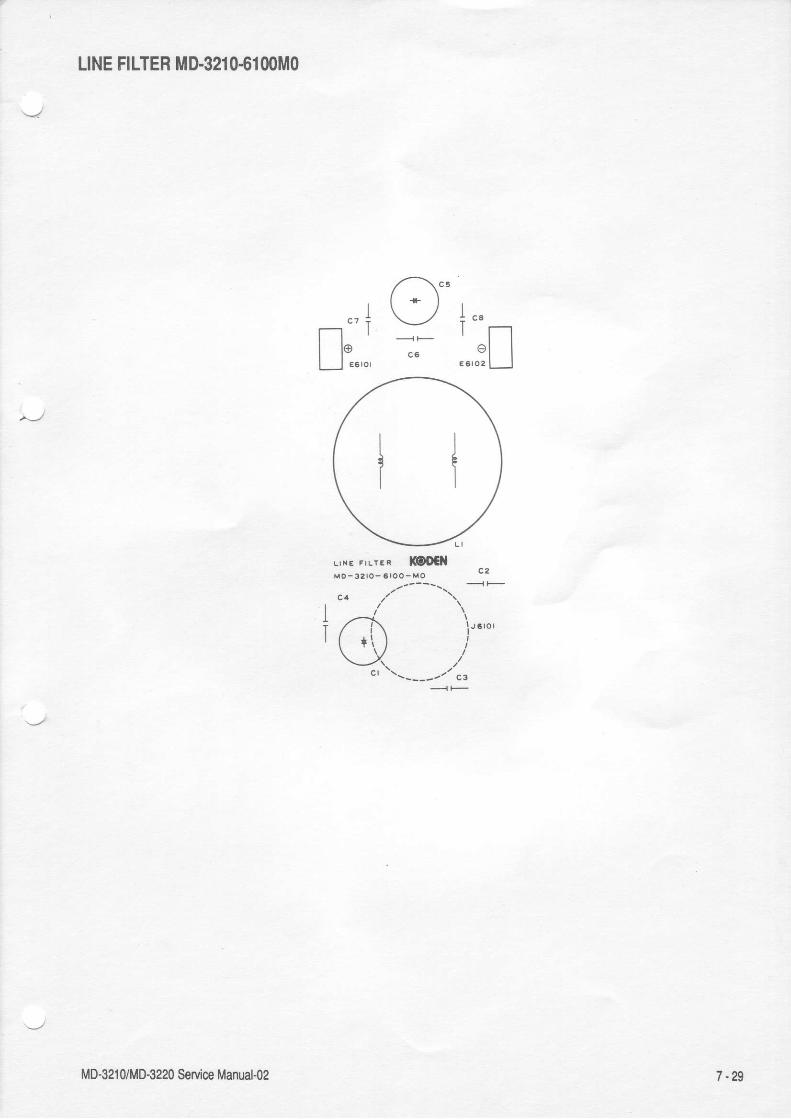
LINE FILTER MD.321O€1OOMO
LII IE FILIER I@OCIIM O - 3 2 r O - 6 l O O - M O
- , 1" , 7@
[ * J +""_' l lo l I
MD-321 0/MD€220 Service Manual-oz 7 -29
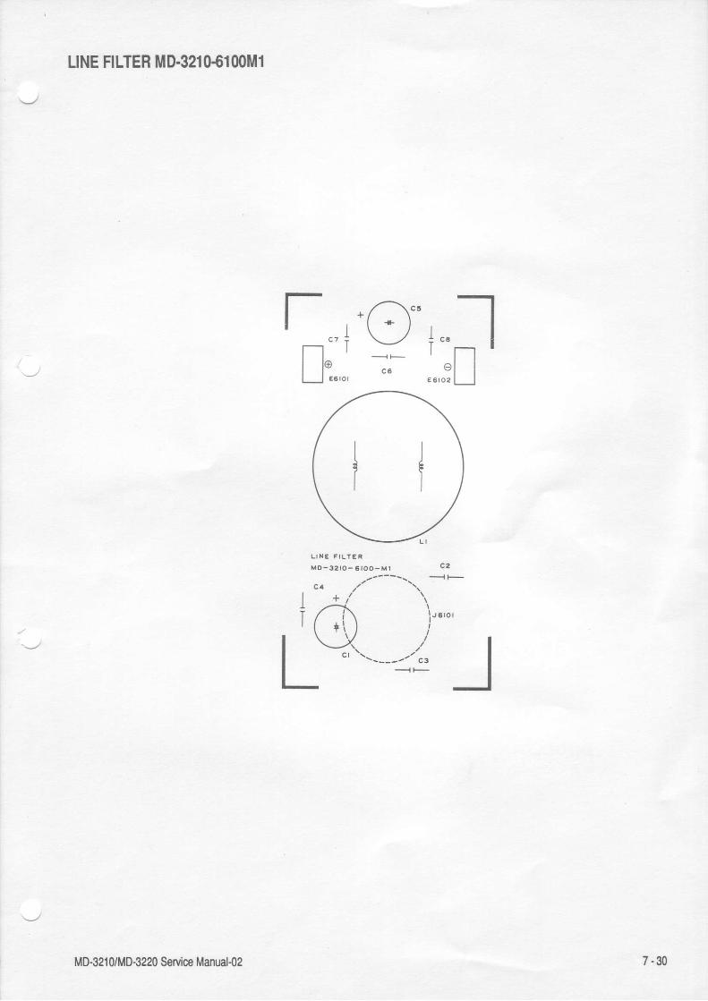
LINE FILTER MD.321()€1O()Ml
*/1". -l
l ' * l I\--l i "",--- |
t lc 6 " l IE5ro2 [__l
rT
jc ? :
I@
M O - 3 2 t O - 6 t O O - M l
7-30MD-3210/MD-3220 SeMce Manual-02

- t
Y=- l
rsjl
POWER SUPPLY MD.321 G6()()OM1
-l
t---LIIIi--lII
t l
' ,,--\ "i 5 4 i / \ E. l , i I'
\-./
IrF I
[il' "'.IFtu*,+,+,+ L=------l "n*,1 F} SBi,ftb:{ ,r ,2.n'lI I + 5.'2---r ,,-- "'' 'nQV -J- \7'
={ l I s{ ) , -3 i - r - " " '
( r \ l I t r - v . r I l l r r ? +\ ' / . A * * ' " : - ? a i * r r
\--l o.o
I l - --- ] l - -- l e rr l l l "+ l q l l l l r " * s t r l l l l :
I t -_-_l l ---- l . r r l l '+ l , l l l | . ' " * s t r l l l l ' '' ' t t t l
" I l l l r - r i l r - r - - ; lo , l l l l " ' r i [ i l ] l l l / t l | |I l l l - t ; ' - k | l l l l l ( + ) r l: n t l - _ \ , / l I- i l - .e . ,
- -s YC
; f-^l l l l F",," MD-3zro-6ooo-M1 f- l _ rt \Jdl l l l l l : r r ,3_ (J ,uooc '
n :\_,,r e
II
MD-321 0/MD€24 Service Manual{2 7-31

POWER SUPPLY MD.321S6(}()OM2
t t t t t t t lI t l t t t t t
6 l : l 6 l o l 6 l L l s l a l
' /,-.\ oa ! i / \ t
. l r I- \ _./
1
" T
+ rF (rs
['--.1l 1 l
8,e?fA'ttl- 't,_ui\_/u.teJ(J
""v c I i i
s-.{
: """
t lt lt l
t lI I
t lt lt l
! !. "", {-v r- ^ , , - ^ Y \ r!t -,/ ,'\ 8 | ll
" . ' * = l I l l l lgt "-",
: *:+f_
" r*;'+ srla ', ii-ll
* \ r l l l l
7 -52
IIlI
otr(^);'
" [ l_ l_. l ? l ' l
| ,,--\ r----_--t t c?] -l | | |I { ) t t , " t : . ' I t , i -
tl v L__t*'rl'l-1 :-_-"+l-A i ' ^ ' ( + ) ' q : . =e\ + ,r" \.__-/ .,:.1 vl
MD-321 0/MD-3220 SeMce Manual-o2

POWER SUPPLY M0.321 (}.6OOOM3
f- r-I : t Itil' Il ltgl L-T I- " 1" l
I
' ; [ -
" L"t--. L
t :'- --ll -. l I l e l
r A f - - - l - 1 " ? - l I l l -Fi v--_!l*''l"/1;--*ii-
uJ;
TIl lt lt ll l
t___to
l t t u
?i'H
n l o L _ l
" ""l........'
+ - tg l- 3 --f-
IJL-
.-"',,1----ti q/\t -'"''t / L!!--a-aJ \
3l, , ' - - \ ' - - f l ' * / w \ t/ , \ t t / \ " ^I + | l t | \ - /
I l l | -
V! " \ /e l - | lr-:-i=f)_ _l-"
7 -33
'iffriiiq, ; ; ; s:fi ; :i,, **ir-#".;t' "i5,1 i*t r-----r r'', ;e". [ ) ru* "" - - - { = l ( | | , : l l r ' \ - J ; l
MD-321 0/MD€220 Service Manual-()2

LOGIC UPPER MD.321().7(}()OM1
r ( O F - @ O ) €' - ' \ : : :
-1
Ln - V- *Y-
. - r Y - F l l n i ' | |iR !ll =ll,11 rf.l:LI I* [-l flr'-
-it'- |
=r irr li:rr,n =l lll,'i-L] t IU L] =L.J LJ U *il ,,'* ;! ll,
,, 1 tl lr tl ir: l | . l l r ll , l l = , , I L J l L J : L l i L l
l l ' : l i : t- l t t tr i l [ . ]-Lr " ' r =l J : i l r i . l lLi L-l i
lu',1 u[l u[l uf] ;
! l ' n . t r . , -
l i ,
i l i l r r l = i t r l . r l ' l_ i, l l l I J I, l :^l t. l
I - , - ' , , _ l - r f - l
! , ;1 il i I u,flili"l r,;l ,[.1 iI | "t" i I' i!, s;i, - Jj' s
I I ruh'l' tr ,i r r'rt r I =l F* l I ] ! | h ' - ' ! l h l l J I l lAt - r " l l l i i l , r i ; 1 ;q , i , II I I i-l l-l l-l il l-l l-tl 'J;I=i'J'Ll;iU,:i ;l lir n 6 r / - ) * o r - ^ f d j - =
=r =r v?,, _r \ri,--' .-@ : J
r----r i "I I I '
I r .L___J 3
:
t t I
t l : l | |l r - ' l lI t 9 | | |. . , , " 1 1 1- t '; * u \
tt
f l I Il r l l' l ' r lt I : LJ;5
"i,n , l lLJ ' L.I" T--lr l f t r rl l - ' l ' lll=lllrL J o ' ' r-r il, l : l l| : t lt . i l L
r-----1iiJ T-TT- l
l : zI - J
- o';1I -rEl II lI Ht "t _l : ' r -t :
l -LI L - !l rIt .
____l c'- : ,
t - i
I . ' *| ,/\r L);IIl -Il i . :rl /'_\-
r L )
ritl&
t-l
l l ,L Jt-r. t .
LJ=+ r t l
_i
, I
JJ
(-
:
;
-
It l
t lt lt llI I- ' l l
.'5n, l
r lt lL J;.J
t lt t _t t :L l -
i-rt ll lt^lt.], lIl lL J
7 -34MD-321 0/MD€220 SeMce Manual-02

9e- z zfienupn arruos 0zze-0n/0tze-0n
T --'lt s ( O @ l O r . F L ) l v H
(J N F Gr c la c?5 c la c tz_tF
, n "O . .Qr r= r " . i l = l l [ ] = l l - 6 r
+f l;E n iln n frRlr ll't_l ; L.l 'Ll r-r-' - ! r r r r r r . r a r r ] l t l l d l ' l i ' " t $ , , ' i { Iji',],i ]' li i' l'l=,1 i l*L:=t ii I ti-=lF u:,,,'*. _,!,1i," ,i.' r,
'' ; -, !,,, H
tlF 31':-t -,Qi,, '."'r " ,-, ?* H 'l*[;[a [ - ii l, l,ll-1, ii i [ Ll,"i
['l+l lifi t;Ll L]' .r il .i
tl t
"Ll
I tz,
c 7 tc 6 2 c 5 !
f i , r r 1 1 l i a I l ' | l ' m
: r l l t l l r l t ; l l " = ; l _ l : i T . ),r ,.,,-* L
'Ll ,,,.-* lE L:l lll '- ' 3 | | ; Y
i r1 , " , { r . . ,_ r l t l f l ; t l I l ! -0 .4 c r r ' F + L l c5 i I l ;
| ; r t , " n = r r . l l f l f l ; t l I l ! -L - i i l l ' l l = l l i i t = l l e l l t l l ; ! ? e . - r u J
' : I l - t L l L l i L ' ! l l t - J 1 , . : - t t ; r - -, , J , l t l l f t ! f r s t l t _ J - = : t l i r . - r l* { , , . ^ : : . ' , ] ' _ ' * t l t l I ' l [ , ] " ' l l i | ; t ,Ht l l l i l i l ; g i i l l ' l l l ' l ; r r ' r r r =I r i r r ; i r i , ' J t l * l J i L l i L ! ; L i u I l l l ' iL--i = l_j',,,'=J= ^-t: J ^-i .,'^T ,"^-i :T
'lt:_ - "
ltT'[,[ [: [' [' [,i][!' ,L! | | | ; ; r i : : ^ - ^ ^ . , t r , c ! ! c , ,'''i'l
l] u p. |!uul]| i,J, ll,* tl {i,L]f t,t \_y'* .'\t*
F F ( O @ \ r c r r . F C J l $ F
L ( J N F E r
I
zm000z-0 Ee-out HSddn cleol
zl lr l; II IL_l
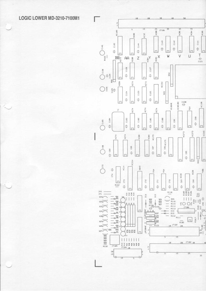
LOGIC LOWER MD.3210-7100M1 t-
; l t . r? cT r n l lt t t t t l
* l l l l e l l" l l l l - l l* l l t - o l - l - o l' t-ol
fl: l I" t l
n l l
l "Iu
E
nt lt lt l .lnj
&
i
;
;
€
t tt lt lt tL
I F
r s i: o 0 i: ! i
t t't'1uv| | l l
r
he -t
1.. | ,
* r r H3 l ls l l s
t l- ! t t r- l d -
3 5 : 5| l | :
.80 0 i ;J7106
'- F-"rR -
t n l
cn
- l lo l l- l - t l
BB:t-l Y
I n| | t l
l I l"Ll lnlS U .
?
n' l-l' - l lt lldI
t lt lt l
:/-\t l
B I
A - n
U Y Yn n l rl t t l i l l
| ' | i l 1H + H F H
r r 9 t | | |
l n . l l ; l l $ l liu Hiu uiuiH
3! r---r : r---l
r ] + l l ? | I\ _ / t t t l
; t t t lt t t lt ^ t r I I
R r 6 2 , l l' t c u
:
,-\
| | lI t l
q3./-\ - g-r
"'5 +.03a-\ - _.
-- --#'o3l/-\
__{rg.*dd -og,
o2sl1 - !.1,
*J- -o"f .^-_:!r !!'
E r-r! : t I@ t IE l IRt3Z J7r05
P fft Tt Ttt t t t t l
- t t - t t - t l! . l t s t t l t l
t t t t t lr t t - ! t t - r - t l- L-oJ - l-ol - l-olR 1 r 0
E ;
l E i l i a . - R r r 6I - I - - R r r sI Rr i l " t . . ; ".
J f - . - - " l f _ r r r : I! E C E - - - - + a - D r a r lPl 1037 ----.*r- Dr3 |
FEre - R'1r?.,_,-4[61:+d. ' $ ra$,; r--
+nl lIJnt ll-J
nt l
tJt l
9 i En n n nI l - ' l I l l : l I
l l ' l l l l ' l ll l r l l l l r l ll-oj - InJ lnl - l.o]w v g T
I F
; J? lSr
Int t ot t ;l l '
; X
nt l
t lt lLfl
3|--'l t| "l l et lt ltd
I
nt t 6t l et l 't l - Ll-01 -
5 1 5
n nt t . l lI t : t Il l r l llnl - Lol
A A B Z
n n8 t t t l' l l l l+ lJ l-l
I :3 H
n f ti l l l l I; l l ; l l- LoJ - l.oj
? E_ n . n: l l : l lr l l r l l- lnl - lnl
F--is-------t--l

Ii
nt tt lt lt ll-nlA
pnt lt lt ll l
t lt llnl
S s B Br i ? P P
l l n n n n nE l l E l l i l l r l l s t t 6 t l' l l ' l l ' l l ' l l ' l l ' l l. L l l r l l . ! l l - L l l - ! l I ' l I
l . o i - l n i - L o l - L o l - l . o lL K J H G F E D C g
pe0A227a X 16
;
3n
nl lt lt tt_Dli M
ftt lt lt lt ltot
tt
3 H
* | l * | |. l l . I I- l l - L l l- l-ol - l-ol
- P I Nl t -i r -
n t lt t l ll l = l ll l ; l lL t r r l l
:
nt lt lt lI It ltol
R
; * $ * * s F * Ei r r l ? r - - 1 H T l P P
n I l n l l n l l n nI l , l I l l ' l | | l ' l I ' l l | | G| , l t l t - | l llnl ' lnl lnl - lnl hJ + lol + lol u
P :p ;f--_'r -J-I t rl 1 3l l it ll l
t t "l t t
t
n t ll t l lt t t l| l t lI l s I II t " t lt F t tU- Lojtle
5
nt lt lt lt tI It ll-ol
5
nt ll lt ll l
l llni
E e
ft T.1t t t lt t . t t -l l s l l st t t lt t - ! t t rt t -L-Ol
. r f l
} I F Lt :6 n
r [ ) r e
: ' | f
|, af__ll ll l
vR9 VRS VR7---{Er j311
l-:fJ- L-11!flJ lrffi*pl r-l:l!F lY'oro '{l
MD-321 0/MD-3220 Se,vice Manuato2
t?..F..F uo
7-36

3
- t l
, l
t-o.l
; J71Sr
i
t t dt t :t l "l l -
r-lt tL___t
-{ F c15e
3 g? ?
N t _ ]t t , t lI t : l ll l - l . l l
td - l.ol
nl t -
| ;
A A E zft
- t li l l- ' l l
crsr { Fs
t lt lt l
8 l l+ t l
i : - E
, t-t: t l5 t l
IJ19?
LOGIC LOWER MD.3210-71 00M2 r.
V U . T .I Fc 1 2 t
I l,lllt-lH Ii l - l
l l lH "
i ni 5
n 'l l -l l [L u g
.:d:*-:
, | li l l- t I-
Loj
= x t l
nl l| ;l.ol
n E l ll l n l l| " t lt t t lLol E
J
n lI t s l| | J ll l - lln l L t r
PP l * [
I t E lE I I E I- ! t t - r l- l . o l - l
$ Ef-t nl l o l l -
| : | 3l l ' l l - - ulnl - Lol -
: i3 t s
n f tt t - t t -
t t " t t "t t r t t rl.ol - l-ol -
3 ;9 9
Tt t--t. | | t l3 l l l lr t I t l- hl l-ol
5
- i l , l , l i l ;. . l l _ . l l . . l l _ . l l -- Lol -- Lol - l-ol - l-trj -
nr8e FlEXE4 R1o6
: i.'W-- !r9irrP, E, in - ! : ! - n- , i
-^ - -
I E I g -;l i:, 'r""v!r-i| ",|UE l*.,, - lll:'L-----J
. , lF l l - - Rrr3.FFr--- - - : -! E C A - - - - { - D 1 a I I$l-]orz ;::*- ",g*ss
- Ltrl-i_+ie ;i;;," - - llli iF_IElg6 'rre. J5e.
--r L_______JBu - R lzS oV; Rr?? - - Pr6 .3 nrrg -
ni", - Rr€s
e ,r{Ev v6 \--l L-l
n t s
I. t l
: : l lc + t l
9 ' IJIJ:t t a
I n3 i l t l
c+3.1_l Ll- * U .
3
C 5 r + lt ll.ol s i f E
i " . l F c " " t
n r ] t lt t t t - t l| | | l , l Il l l d + t " lt-ot
. r ?! ! s
n n t l rl l , l l l l lh l + u F h
9 9n nt t l lLl H
5f-lt lt lt ll lLDI
l t -. . . +E ' ' g sr E "
:
I
( ) int l| lt ll.ol
nt lt ll-ol
f-ll lt lIJt l! t
r r c 5 3I l ' / '
I T L
; -IE E E E
EXT. TRIG ̂--rPd------l Ui'rP]Elx.H
- ' --.Fl
Eiid - : ;
*3 _-#o*)z{ -oHl
ozsl_\ - 1:
*d- -oS
o.'){E;E

A E E A E g E S * * o
r l l : I : l : l : l l r I : l : l r l , l U s*U * [ +H+ l ' ' l + H+lJ + lJ +lJ + ror - r . ,=r t_ lS p . p 5 N i M L K J H G F E D c s H "fr : E !8n1227. I 16
t J - 1 = | , l W i BI u i l l - ! 1 f l f l f l f l f l f l f l 1 l t e l[ l l l l I l l l l l l l l l l l l l l l l ; H 7I * = |J, I I "M!! IF,
f l s n + g s I s : e i r EH v l l " n E r - r ? r - r ' 1 n in r l l l t l l f , l l l , l l r
ll: Ht[]lu t -, br +rr HtH;u u 6t n l
g g [ , - L A ; ; s E s - Er n l n t l t l l . u - n - r * I u [ l - I s' I llll Ilhl | | | : [l ; ;'--|"r i^L]-H :,"4 ; !+ hJ H lJ S t"r r-trr # "; -" ,*":; io;_p
u ,*u *r., iEn.+11- rru" .'11[*;?15- 4|| ,l Ui'hffil: UJl*;!^;;Jh;iAfr 15=*1iHhF='1i:: T-1.*", "t'n I ii? F:lisL'f^ F, [];Jtti'P#1t1 ;;"1'c* l: ;;p?,JTrl.Sr#,.P..V roi ;1 +i'p-1',.*g"u n (F r't Er =;,*-il="_,€:|_ j f l [ [ l ; r+ ; l le r i l l ' " "J ; l l F t : { ]e t s l : l " r -e t i , ,!fhUA"+'' H ri ll r 3,LJ +*? :(P.il'Ip"c'aq"- *oj $, {i i;,fft*,gfft T*------*r L__l L__i [f-fl-[n [r-fr'5#'
;E@j'r ##'rr"A$# "q#r"&
MD-321 0/MD-3220 SeMce Manual-oz 7 -37

I
CONTROL PA'IEL ilD.32m-mnffi 1
3
I
r l" , t ll*'; I I_ -I-Ttr
./ \ "'l-'3 \ , / . ' -
1 r-,o ' e la 3 \
fi ;f)'! r - \--'lAt :.- --= e e (
t\-___.,-
r l^ r /./
_ " t - - ti i i ; r ' . . I
t t !t t :t t a
I
MD-3210/MD-3220 Seflice Manual{2 7 -38

COI,ITROL PANEL M0.321 (l.72(l(lM2
ni l !u ;
J
7 -39
T.l. , t l
t l+
z r/- -'
J .zrO \!-z'
L / -2 ? {i \
MD-321 UM0.3220 Seryice Manual-o2

oiffi
ffi
\9
Ol e
CRT Main board PWD1050A

MD-3210/M0.3220 Service Manual-o2 7 -40

CRT Neck board PWD1051A
7 -41MD-3210/MD-3220 Service Manual-o2

T
I*t-183004 .'?Rloo6 /Y
8.3 ExPloded View

a MD-3210n220 Se ice i,lanual{2


R3005R3013
\
.n\---#. ' t i ,% f f i
, . ' - l M t
l ' r f f i (k s )I Y) .(GY
. . , . ' M ,.,,.
Y | ,--!l!ol.,,' (6r\Vi
onnnoRiooi . an^iR
I i
ffifo*./- ffi,f -!rorr_t€ vk*nl.A B3oor i, ff
st--/A\- 83012 \
|W soon.Y1/ AW/- -%
W.__81016
V*Roo14_ o|[q\=rr*
/ '4/ \__B]eMnoorr ./ =^/-*on
E
a
)
6 '.TWDESlGNEDuoott MRT-134 / MRT-I40 TITLE Scanner Box
KODEN xma E-Ecno{rcs c!,, LrD,Dr{G. '!0 23W593g9 leace
8 - 3 6a MD-3210/3220 Service Manual.02


UB
N

| -" -.---*^
\ v '5\...*22--l-i) $-\
F
n
n
*----------_*_
/)
€At : :
tllI ' hl r lI
)
u 9WDESlGNED
tHOOEL TITLE Drive Unit
K@DElf rmr arslno{rcs m,, LrD.0w6. Nc. 23W53390 leaci8 - 3 75 MD-32'|0/32m Servics Manual{2

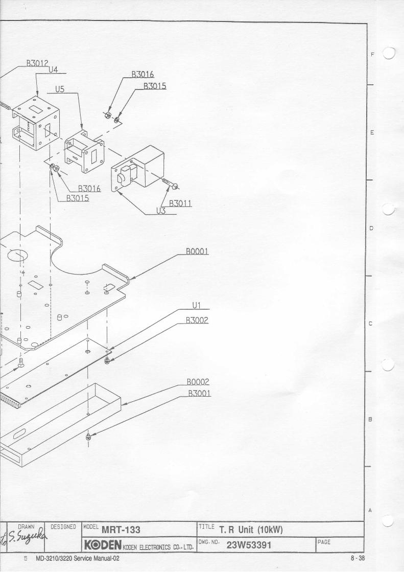
. )
5 MD-3210/3220 Servioe Manual{2
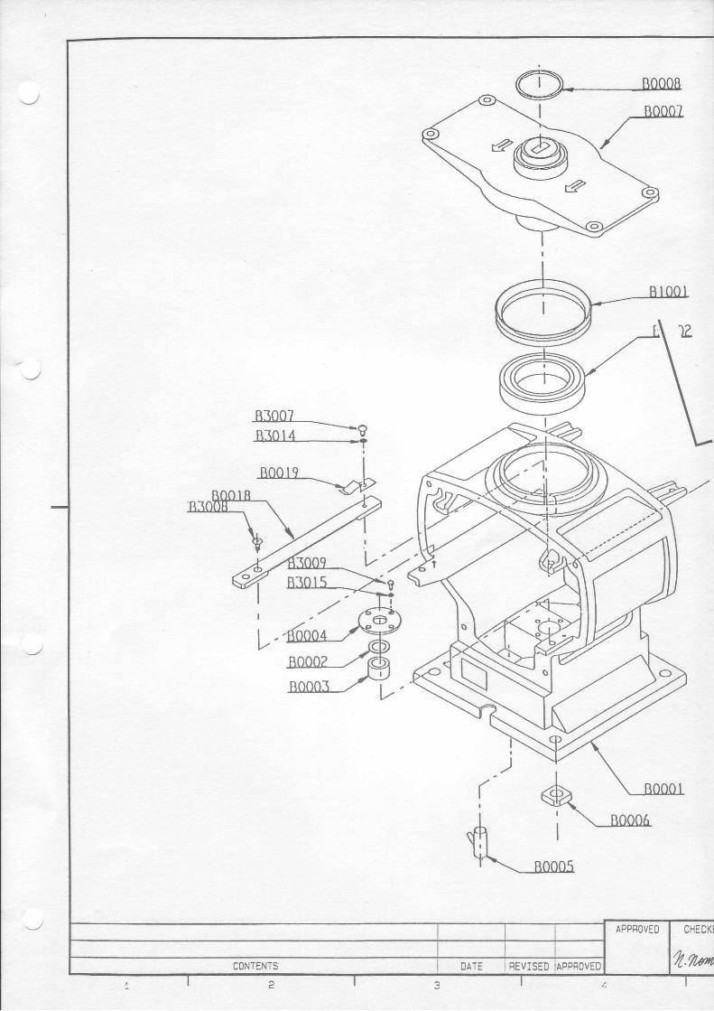
.BI0CI______.___R30r4 _Y
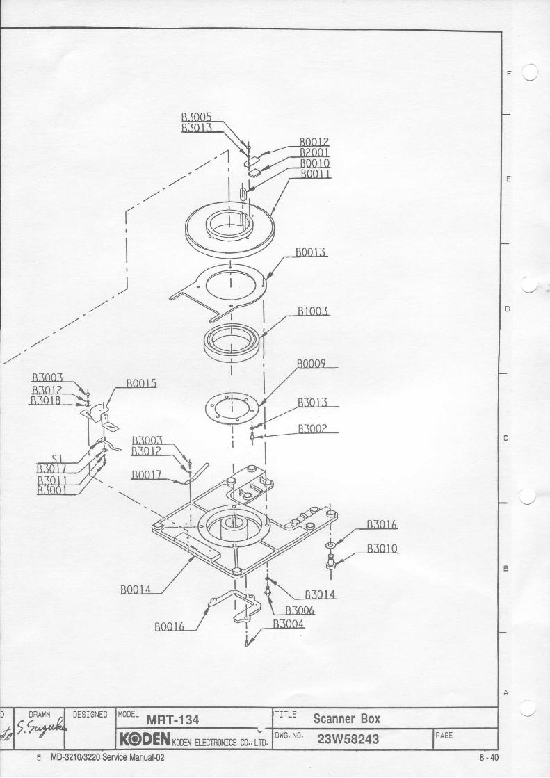
81005R 3 0 1 3 \
N.---+**+. ' ' ;Fr 'N ',.-' I v('/ rd{l V . * , I) 16./
. r - t ' ' Xl...- @r.,,. _--r , AQ09_nlool . n^ol5
ffi*./- e*----t€ Y'l--'."-lA- Rrooj i +-i
Mrt\- Bror2-\ l
H M %
Deoral tdM-
noota ./ vT .-ni004
V
E
D
n
A
tuDFAXN .
tt4DESlGNEDnoo"
MRT-I94TITLE Scanner Box
KODENrmsr E-Ecn$rs co,, LrD.DriG. N0. 23W59243 PAGE
8-405 MD-3210/3220 Service Manual{2

t2a
f ,.ry7'''(.''
)'
\-i"OPTION
,z
, ,
'
4r72
OPTION,ou-$t9
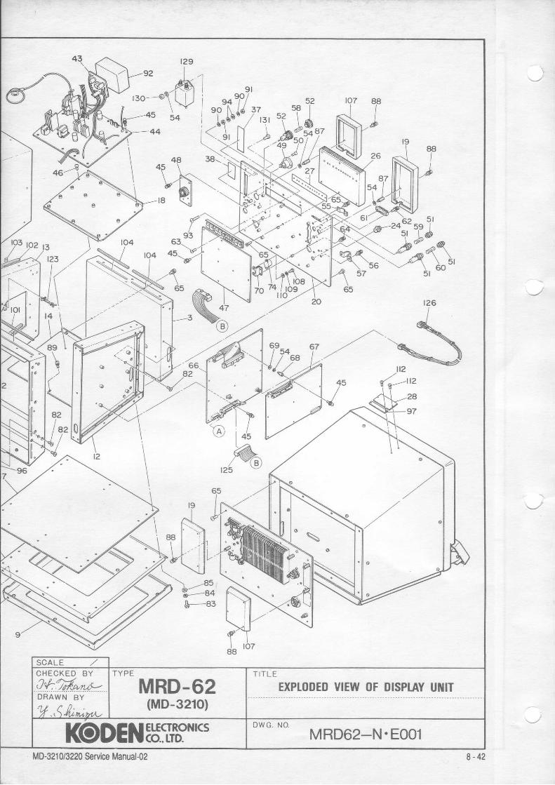
t4
a2 4./- \a2
v=;"&-83
MRD-62(MD-321O)
CHECKED BY
Q*:Mr4!*DRAWN BY
TITLE
EXPTODED VIEW OF DISPIAY U[{IT
l(oDENErfcT'RoNr(sDWG, NO
MRD62_N.EOO1

- --1
APPENDIX
ftiS',"1 ---L:
EXCK ----------------
l , -DV?DV6DV2AZTSST
cRco
RADAR I,sIKCI}I4
1. BIOCK DIAGRAU
InternalD( D7
L S ICONTROIJ
I ""uu. ".,I r < c D - 2 4
A0 to A:D 0 t o D
] I I ---1-it___: c P u
RADAR LSI KCD-24
VDD: +5 V sou rce99. 102, 108, 11't . ' , t17, 120. ' t26, 129
vSS: Ground (GND)98 , 101 , 105 , 107 . 110 , 114 , 1 ' 16 , 119 .125, 128, ',132
+5v: Not used in l '10-321-/3220. connected to56. 57, 58. 130
GND: Tes t p i ns , connec ted t o GND.3. 29. 54, 55, 75, 77. 1O4. 1O9, 112. 113.115, 133, 134Not used in l ' lD-321C/3220. connected to GND.49 (A6>
I4D-32IO / 3220 Service Manual-Ol A-I