kobelt: hpu100 accu-steer hydraulic power unit
TRANSCRIPT
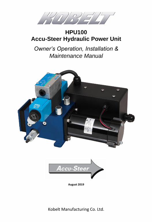
Kobelt Manufacturing Co. Ltd.
HPU100 Accu-Steer Hydraulic Power Unit
Owner’s Operation, Installation &
Maintenance Manual
August 2019
HPU100 Hydraulic Power Units Kobelt Manufacturing Co. Ltd.
Rev C MNL-HPU100 2 of 32
NOTES:
RECORD DATA BEFORE INSTALLATION FOR FUTURE REFERENCE
Model #:
Serial #:
Date of Purchase:
Date of Installation:

HPU100 Hydraulic Power Units Kobelt Manufacturing Co. Ltd.
Rev C MNL-HPU100 3 of 32
TABLE OF CONTENTS
1 Introduction ............................................................................................................ 4 1.1 Contact .................................................................................................................... 4 1.2 Safety ....................................................................................................................... 4
2 Product Description ................................................................................................. 6 2.1 Components ............................................................................................................ 7 2.2 Technical Specifications ........................................................................................... 7
3 Installation ............................................................................................................ 10 3.1 Mechanical ............................................................................................................ 10 3.2 Hydraulic ................................................................................................................ 10 3.3 Electrical ................................................................................................................ 11
4 Commissioning ...................................................................................................... 17 4.1 Hydraulic Fill & Bleed ............................................................................................. 17 4.2 Electrical Check ...................................................................................................... 17 4.3 Functional Test ...................................................................................................... 18
5 Operation .............................................................................................................. 19
6 Maintenance ......................................................................................................... 20 6.1 Preventative Maintenance..................................................................................... 20 6.2 Recommended Spare Parts .................................................................................... 21
7 Troubleshooting .................................................................................................... 22
8 Warranty ............................................................................................................... 23
9 Appendix A: Installation Dimensions ...................................................................... 24
10 Appendix B: Parts List ............................................................................................ 25
11 Appendix C: Manifold Assembly Parts .................................................................... 26
12 Appendix D: Typical System Arrangement .............................................................. 29
13 Appendix E: Brush Replacement ............................................................................ 30
14 Appendix F: Shaft Seal Replacement ...................................................................... 31
HPU100 Hydraulic Power Units Kobelt Manufacturing Co. Ltd.
Rev C MNL-HPU100 4 of 32
1 INTRODUCTION
1.1 CONTACT
Kobelt Manufacturing Co. Ltd. 8238-129th Street
Surrey, British Columbia Canada, V3W 0A6
Sales Tel: Fax:
Email: Website:
+1-604-572-3935 +1-604-590-8313 [email protected] www.kobelt.com
This document is intended to clearly present comprehensive product data and provide
technical information to assist the end user in design applications. Kobelt reserves the right,
without notice, to change the design, or construction, of any products and to discontinue or
limit distribution of any products. Kobelt also reserves the right to change, or update, without
notice, any technical information contained within this document.
Kobelt recommends that customers visit our website to check for updates to this Manual.
Once a product has been selected for use, it should be tested by the user to ensure proper
function in all possible applications. For further instructions, please contact our distributors or
visit our website.
1.2 SAFETY
1.2.1 Safety Alerts
Throughout this manual, the following symbols, and their accompanying explanation, are
used to alert the user to special instructions concerning a service or operation that may be
hazardous if performed incorrectly or carelessly. The associated risk levels are stated below.
This symbol indicates an imminently hazardous situation which, if not avoided, will result in death or serious injury.
This symbol indicates a potentially hazardous situation which, if not avoided, could result in death or serious injury.
This symbol indicates a hazardous situation, which if not avoided, could result in minor or moderate injury.
This symbol informs the reader of events not related to personal injury but which there is a risk of damage to property or equipment.
This symbol informs the reader of safety-related instructions or procedures.
HPU100 Hydraulic Power Units Kobelt Manufacturing Co. Ltd.
Rev C MNL-HPU100 5 of 32
1.2.2 Notice to Installer
Disregarding the following safety measures can result in an accident causing severe injury to
personnel and damage to material assets.
• Only use the product as directed in this manual.
• Never put the product into service if there is evidence of visible damage.
• Never put the product into service before fully completing installation and
commissioning.
• Do not carry out any modifications to the product.
• Only use authentic Kobelt spare parts.
• Observe all local regulations, directives and laws during the installation of this product.
• All installation, commissioning, and maintenance work must only be conducted by
qualified personnel. (For the purpose of this manual, qualified personnel are persons
who are familiar with the assembly, installation, commissioning, and operation of the
product and who have the qualifications necessary for their occupation.)
• Observe all specifications in this manual. If these guidelines are not followed and
damage occurs, the warranty will be voided.
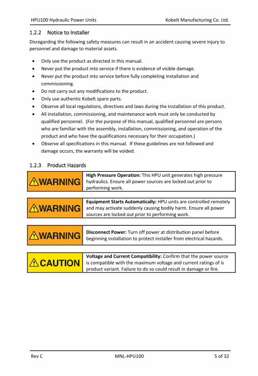
1.2.3 Product Hazards
High Pressure Operation: This HPU unit generates high pressure hydraulics. Ensure all power sources are locked out prior to performing work.
Equipment Starts Automatically: HPU units are controlled remotely and may activate suddenly causing bodily harm. Ensure all power sources are locked out prior to performing work.
Disconnect Power: Turn off power at distribution panel before beginning installation to protect installer from electrical hazards.
Voltage and Current Compatibility: Confirm that the power source is compatible with the maximum voltage and current ratings of is product variant. Failure to do so could result in damage or fire.
HPU100 Hydraulic Power Units Kobelt Manufacturing Co. Ltd.
Rev C MNL-HPU100 6 of 32
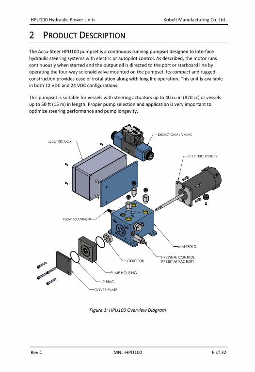
2 PRODUCT DESCRIPTION
The Accu-Steer HPU100 pumpset is a continuous running pumpset designed to interface
hydraulic steering systems with electric or autopilot control. As described, the motor runs
continuously when started and the output oil is directed to the port or starboard line by
operating the four-way solenoid valve mounted on the pumpset. Its compact and rugged
construction provides ease of installation along with long life operation. This unit is available
in both 12 VDC and 24 VDC configurations.
This pumpset is suitable for vessels with steering actuators up to 40 cu in (820 cc) or vessels
up to 50 ft (15 m) in length. Proper pump selection and application is very important to
optimize steering performance and pump longevity.
Figure 1: HPU100 Overview Diagram
HPU100 Hydraulic Power Units Kobelt Manufacturing Co. Ltd.
Rev C MNL-HPU100 7 of 32
2.1 COMPONENTS
The Accu-Steer HPU100 is a complete pump assembly consisting of a gerotor style pump, adjustable flow control, adjustable pressure release valve and an electric permanent magnet motor terminated in an electrical junction box. As the pump set is self-contained, installation involves connecting the unit to the steering lines and the electric control and adjusting the unit to the requirements of the steering system.
2.1.1 Electric Motor
The electric motor is a permanent magnet style D.C. motor featuring ball bearing supports and replaceable brush gear. The motor is directly coupled to the pump unit by a machined face. The electric motors are available in both 12 VDC and 24 VDC voltages.
2.1.2 Pump
The pump is a gerotor style gear unit with extremely quiet operation. Hydraulic flow control and pressure relief are adjustable. The pressure relief valves are factory set for 500 psi. and should not be altered in the field as it will change the electric motor current draw.
2.1.3 Hydraulic Manifold
The hydraulic manifold includes directional valve, flow control, pressure relief and by-pass
valve. it also acts as a base to hold motor and pump. All adjustment and hydraulics line
connected to manifold.
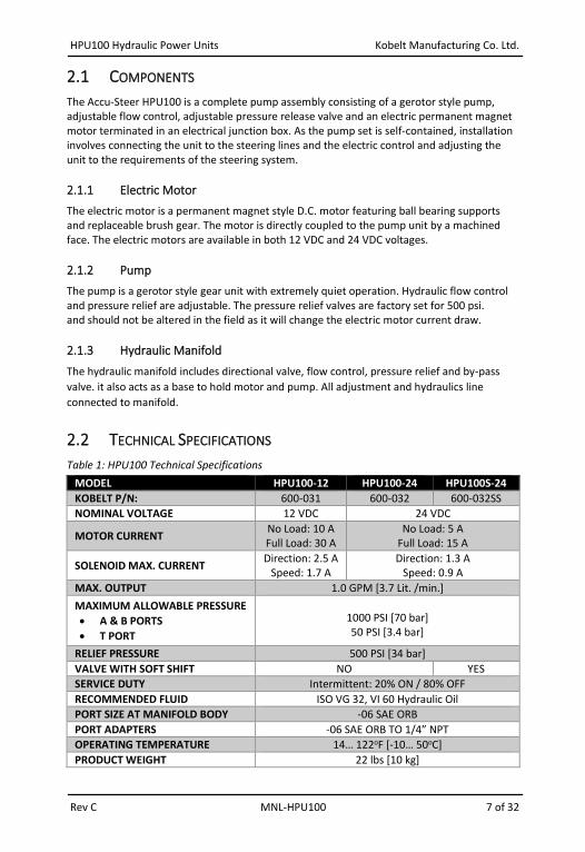
2.2 TECHNICAL SPECIFICATIONS
Table 1: HPU100 Technical Specifications
MODEL HPU100-12 HPU100-24 HPU100S-24
KOBELT P/N: 600-031 600-032 600-032SS
NOMINAL VOLTAGE 12 VDC 24 VDC
MOTOR CURRENT No Load: 10 A Full Load: 30 A
No Load: 5 A Full Load: 15 A
SOLENOID MAX. CURRENT Direction: 2.5 A
Speed: 1.7 A Direction: 1.3 A
Speed: 0.9 A
MAX. OUTPUT 1.0 GPM [3.7 Lit. /min.]
MAXIMUM ALLOWABLE PRESSURE
• A & B PORTS
• T PORT
1000 PSI [70 bar] 50 PSI [3.4 bar]
RELIEF PRESSURE 500 PSI [34 bar]
VALVE WITH SOFT SHIFT NO YES
SERVICE DUTY Intermittent: 20% ON / 80% OFF
RECOMMENDED FLUID ISO VG 32, VI 60 Hydraulic Oil
PORT SIZE AT MANIFOLD BODY -06 SAE ORB
PORT ADAPTERS -06 SAE ORB TO 1/4” NPT
OPERATING TEMPERATURE 14… 122oF [-10… 50oC]
PRODUCT WEIGHT 22 lbs [10 kg]

HPU100 Hydraulic Power Units Kobelt Manufacturing Co. Ltd.
Rev C MNL-HPU100 8 of 32
2.2.1 Temperature Limits
The motor temperature has a maximum limit of 248oF [120oC]. Allowing the temperature to
exceed this limit will permanently damage the motor windings. The maximum oil
temperature limit is 149oF [65oC].
Observe the operating temperature range limits as presented in Table 1. Do not operate the
unit if the ambient temperature where the unit is located exceeds these limits.
Exceeding these temperatures may result in reduced operational life or damage to the product.
2.2.2 Pressure Range
The normal operating pressure of the unit is 0 to 500 psi. Avoid operating the unit against the
rudder stops for prolonged periods of time.
2.2.3 Duty Cycle
The HPU100 is designed as an intermittently operated unit for normal steering applications.
High demand applications will over work the motor and cause over heating.
HPU100 Hydraulic Power Units Kobelt Manufacturing Co. Ltd.
Rev C MNL-HPU100 9 of 32
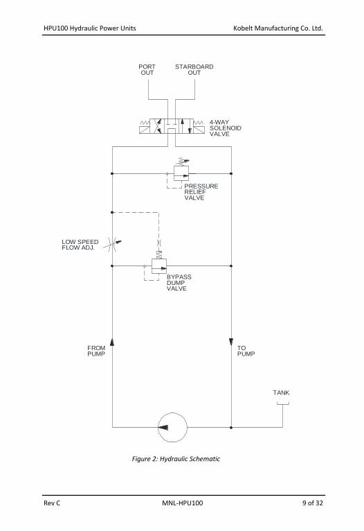
Figure 2: Hydraulic Schematic
FLOW ADJ.LOW SPEED
DUMPBYPASS
VALVE
FROMPUMP PUMP
TO
OUTPORT
OUTSTARBOARD
PRESSURERELIEFVALVE
4-WAYSOLENOIDVALVE
TANK
HPU100 Hydraulic Power Units Kobelt Manufacturing Co. Ltd.
Rev C MNL-HPU100 10 of 32
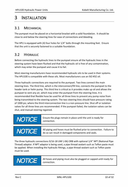
3 INSTALLATION
3.1 MECHANICAL
The pumpset must be placed on a horizontal bracket with a solid foundation. It should be
close to and below the steering lines for ease of connections and bleeding.
The HPU is equipped with (4) four holes for 1/4” bolts through the mounting feet. Ensure
that the unit is securely fastened to a suitable foundation.
3.2 HYDRAULIC
Before connecting the hydraulic lines to the pumpset ensure all the hydraulic lines in the
steering system have been flushed and that the hydraulic oil is free of any contamination,
which may enter the pumpset and cause it to fail.
Most steering manufacturers have recommended hydraulic oils to be used in their systems.
The HPU100 is compatible with these oils. Most manufacturers use an ISO #32 oil.
Three hydraulic connections are required to the pumpset. Two lines connect the main
steering lines. The third line, which is the interconnect/fill line, connects the pumpset to the
header tank or helm pump. This third line is critical as it provides make up oil and allows the
pumpset to vent any air, which may enter the pumpset from the steering lines. It is
recommended that flexible hose be used for all three lines to prevent any pump noise from
being transmitted to the steering system. The two steering lines should have pressure rating
of 1000 psi, where the third interconnection line is a non-pressure line. Shut off or isolation
valves for all three lines are recommended. If the pumpset failed, the isolation valves can be
shut, and manual steering regained.
Ensure the plugs remain in place until the unit is ready for connection.
All piping and hoses must be flushed prior to connection. Failure to do so can result in damaged components and seals.
The three hydraulic connections 9/16-18 UNF (-06) ORB with optional 1/4” NPT (National Pipe Thread) adaptor. If NPT adaptor is being used, a pipe thread sealant such as Teflon paste must be applied. When installing the hydraulic fittings, a pipe thread sealant such as Teflon paste must be used.
All hoses and piping must also be plugged or capped until ready for connection.

HPU100 Hydraulic Power Units Kobelt Manufacturing Co. Ltd.
Rev C MNL-HPU100 11 of 32
The piping to the steering cylinder should be minimum 1/4” nominal size with a suitable wall
thickness to safely withstand the operating pressure. The Port and Starboard steering lines
should have a pressure rating of 1000 psi minimum. Secure the piping against vibration with
pipe clamps spaced every 3 feet [1 m].
The connections to the hydraulic manifold must be made by hoses of suitable rating to
accommodate any movements, vibration or thermal strain.
Figure 3: Connections in Top Face of Hydraulic Manifold
Three (3) hydraulic connections are required:
• Connect two “Cylinder ports” to the two steering cylinders. It is not critical to identify
which of the steering lines is Port or Starboard as most new autopilots will determine
the pump direction and program the drive outputs to suit.
• Connect the the third port to Header tank or helm pump case port.
3.3 ELECTRICAL
The pumpset units are manufactured for operation from either 12 VDC or 24 VDC dependent
on the model number ordered. The Electrical Junction Box contains a remote start relay
(voltage dependent), a thermal overload breaker, and a terminal strip for external
connections. The DC start relay can be activated with a positive or negative switched signal.

HPU100 Hydraulic Power Units Kobelt Manufacturing Co. Ltd.
Rev C MNL-HPU100 12 of 32
Ensure that the electrical cable used to feed the main power to the motor of the HPU150 is
sized properly to prevent voltage drop. Refer to ABYC or local boat electrical standards for
applicable rating recommendations.
The solenoids use a common connection (Terminal 5) on the terminal strip and can be
activated by a positive or a negative control signal. The Port and Starboard solenoid coils are
connected to Terminals 6 and 7 respectively.
Some autopilots have a switched output or clutch/relay output that may be optionally used to
operate the start relay.
DO NOT energize these solenoid coils detached from the valve.
Figure 4: HPU100 Electrical Junction Box Internal Wiring
HPU100-12 contains a 30A Thermal Breaker.
HPU100-24 contains a 15A Thermal Breaker.
HPU100 Hydraulic Power Units Kobelt Manufacturing Co. Ltd.
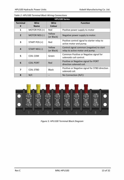
Rev C MNL-HPU100 13 of 32
Table 2: HPU100 Terminal Block Wiring Connections
HPU100 Series
Terminal #
Wire Name
Wire Colour
Function
1 MOTOR POS (+) Red Positive power supply to motor
2 MOTOR NEG (-) Yellow (or Black)
Negative power supply to motor.
3 START POS (+) Red Positive control signal to starter relay to active motor and pump.
4 START NEG (-) Yellow (or Black)
Control signal common (negative) to start relay to active motor and pump.
5 COIL COM Green Common Positive or Negative signal for solenoids coil control.
6 COIL PORT Red Positive or Negative signal for PORT direction solenoid coil.
7 COIL STBD Black Positive or Negative signal for STBD direction solenoid coil.
8 N/C -- No Connection (N/C)
Figure 5: HPU100 Terminal Block Diagram

HPU100 Hydraulic Power Units Kobelt Manufacturing Co. Ltd.
Rev C MNL-HPU100 14 of 32
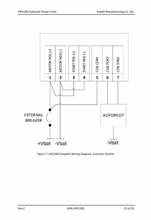
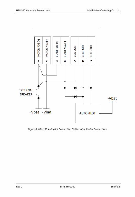
3.3.1 Example Connection Diagrams
The following section contains various example methods for connection of the HPU.
It is recommended that installation work is carried out by a Kobelt Partner, authorized service representative, or trained installation technician. Please contact the nearest Kobelt authorized distributor for assistance.
Figure 6: HPU100 Jog Control Diagram, Common Negative
HPU100 Hydraulic Power Units Kobelt Manufacturing Co. Ltd.
Rev C MNL-HPU100 15 of 32
Figure 7: HPU100 Autopilot Wiring Diagram, Common Positive
HPU100 Hydraulic Power Units Kobelt Manufacturing Co. Ltd.
Rev C MNL-HPU100 16 of 32
Figure 8: HPU100 Autopilot Connection Option with Starter Connections
HPU100 Hydraulic Power Units Kobelt Manufacturing Co. Ltd.
Rev C MNL-HPU100 17 of 32
4 COMMISSIONING
4.1 HYDRAULIC FILL & BLEED
After the hydraulic and the electrical connections have been completed, open all isolating
valves and allow enough time for the pump and lines to fill with oil. Start the pump and
operate the 4-way solenoid valve to check that the port and starboard directions are correct.
If they are wrong, reverse connections to Terminals 6 and 7. Check the hard over to hard
over speed of the rudder and adjust the flow for the appropriate speed. Clockwise to
decrease and counter clockwise to increase.
The pressure relief is factory set at 500 psi and should not require adjustment.
4.2 ELECTRICAL CHECK
Ensure that the cover is installed and secured on the value junction enclosure and all pigtail connections have been properly terminated and enclosed before powering on the HPU100.
Confirm that the electrical connections to the HPU100 have been made correctly and
correspond to the requirements of your system installation.
HPU100 Hydraulic Power Units Kobelt Manufacturing Co. Ltd.
Rev C MNL-HPU100 18 of 32
4.3 FUNCTIONAL TEST
The Functional Test should be carried out while the vessel is still at dock and before it is taken out to sea, after installation has been completed.
After installation and filling, perform the following function tests:
1. Power ON the autopilot (or electronic jog lever).
2. Activate the autopilot (or electronic jog lever) to command motion.
3. Verify that the rudder position changed.
4. Set the autopilot to the manual mode and operate the pump-set to determine if
the Port and Starboard directions are correct.
5. If the rudder goes the opposite way than expected.
a. Reverse the two electrical leads between the coils and the autopilot.
Most new autopilot systems will perform this test during their dockside set-up procedures.
6. Operate the pump-set and note the “hard-over” to “hard-over” (HO to HO) time.
7. Verify that it is in the range of 10 to 16 seconds. Times outside of this range
indicate a mismatched pump-set for the steering system.
HPU100 Hydraulic Power Units Kobelt Manufacturing Co. Ltd.
Rev C MNL-HPU100 19 of 32
5 OPERATION
The HPU100 operates as follows:
• Manifold receives oil from pump, and outputs to steering lines. Output flow determining
the speed of the rudder.
• Output flow is controlled by flow control valves.
• Pressure relief valve is factory set to approximately 500 psi.
• Excess flow is returned to tank via bypass valve.
• By energizing related solenoid on directional valve, flow will be sent to port or
starboard.
HPU100 Hydraulic Power Units Kobelt Manufacturing Co. Ltd.
Rev C MNL-HPU100 20 of 32
6 MAINTENANCE
6.1 PREVENTATIVE MAINTENANCE
The brushes on the electric DC motor can be easily checked by removing the caps and visually
inspecting the brushes. Replace the carbon brushes as required and check the internal
condition of the motor. (see appendix E)
• Monthly (12 times per year)
o Inspect connections for leaks.
• Quarterly (4 times per year)
o Verify adequate oil level.
o Visually inspect wire and cable insulation for splits or damage.
• Every (2) two years
o Sample and analyze the oil in the steering lines.
o Drain reservoir and clean out.
HPU100 Hydraulic Power Units Kobelt Manufacturing Co. Ltd.
Rev C MNL-HPU100 21 of 32
6.2 RECOMMENDED SPARE PARTS
As a minimum Kobelt recommends the following spare parts are on-hand:
Table 3: Recommended Spares
RECOMMENDED SPARES QTY DESCRIPTION KOBELT PART #
1 HPU100 REPAIR KIT (12 VDC / 24 VDC)
• Shaft Seal, O-rings, Motor Brushes and Caps 600-031-RK
When purchasing spare parts refer to Appendix B: Parts List at the back of this manual for
Kobelt component Part Numbers.
Instructions for installation of replacement components in Appendix E: Brush Replacement
and Appendix F: Shaft Seal Replacement.
It is recommended that any required service work on an Accu-Steer unit be performed by a factory authorized service representative. Please contact the nearest Kobelt authorized distributor for assistance.
HPU100 Hydraulic Power Units Kobelt Manufacturing Co. Ltd.
Rev C MNL-HPU100 22 of 32
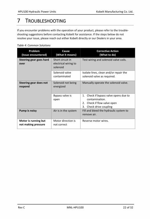
7 TROUBLESHOOTING
If you encounter problems with the operation of your product, please refer to the trouble-
shooting suggestions before contacting Kobelt for assistance. If the steps below do not
resolve your issue, please reach out either Kobelt directly or our Dealers in your area.
Table 4: Common Solutions
Problem (Issue encountered)
Cause (What it means)
Corrective Action (What to do)
Steering gear goes hard over
Short circuit in electrical wiring to solenoid
Test wiring and solenoid valve coils.
Solenoid valve contaminated
Isolate lines, clean and/or repair the solenoid valve as required.
Steering gear does not respond
Solenoid not being energized
Manually operate the solenoid valve.
Bypass valve is open
1. Check if bypass valve opens due to contamination.
2. Check if flow valve open 3. Check drive coupling
Pump is noisy Air is in the system Fill and bleed the hydraulic system to remove air.
Motor is running but not making pressure
Motor direction is not correct
Reverse motor wires.
HPU100 Hydraulic Power Units Kobelt Manufacturing Co. Ltd.
Rev C MNL-HPU100 23 of 32
8 WARRANTY
Kobelt Manufacturing Co. Ltd. (“Kobelt”) warrants the Products and Parts manufactured by
Kobelt to be free from defects in workmanship or material and that said products are
designed mechanically and functionally to perform to specifications.
This warranty is effective providing:
• The equipment is used within the intended operating conditions and in accordance
with Kobelt recommendations
• The equipment is installed according to equipment diagrams, specifications and
recommendations which Kobelt has provided
This warranty becomes invalid if the factory supplied serial number has been removed or
altered on the product. This warranty does not cover cosmetic damage or damage caused by
an act of God, accident, misuse, abuse, negligence or modification of any part of the product.
This warranty does not cover damage due to improper operation or maintenance, connection
to inappropriate equipment or attempted repair by anyone other than an authorized Kobelt
representative.
Upon identification of a potential issue or defect with a Kobelt Product or Part, the Warranty
Applicant (“Applicant”) must immediately contact Kobelt and describe the issue in writing, by
letter, fax, email or other electronic conveyance. Kobelt will then assess the cause of the
defect and determine warranty applicability and appropriate remediation.
If any part is found to be defective, Kobelt will replace said part FOB the Kobelt factory
provided that any such defective part is returned by the Buyer with freight and applicable
forwarding charges prepaid by the Buyer. Kobalt’s sole obligation to the Applicant will be to
repair or replace the defective part with same or similar product, to a maximum value of the
list price of the product or part. The Kobelt warranty does not cover labour charges, travel or
any other associated expenses.
All Products and Parts manufactured by Kobelt, are subject to a warranty against
manufacturer’s defects in materials or workmanship for a period of two (2) years from the
date of purchase.
Kobelt will be responsible for all Products or Parts sold by Kobelt but manufactured by 3rd
party manufacturing companies. However, these products and parts are subject to applicable
3rd party warranties and may not be the same as the Kobelt warranty.
HPU100 Hydraulic Power Units Kobelt Manufacturing Co. Ltd.
Rev C MNL-HPU100 24 of 32
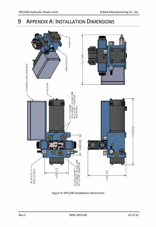
9 APPENDIX A: INSTALLATION DIMENSIONS
Figure 9: HPU100 Installation Dimensions
HPU100 Hydraulic Power Units Kobelt Manufacturing Co. Ltd.
Rev C MNL-HPU100 25 of 32
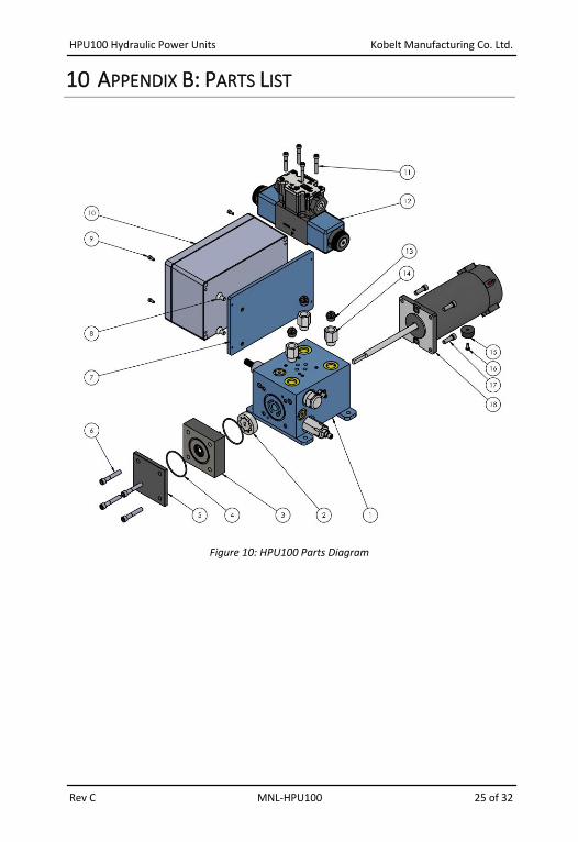
10 APPENDIX B: PARTS LIST
Figure 10: HPU100 Parts Diagram

HPU100 Hydraulic Power Units Kobelt Manufacturing Co. Ltd.
Rev C MNL-HPU100 26 of 32
Table 5: HPU100 Parts List
* Part included in standard repair kit. Not sold separately.
Model No.: HPU100-12 HPU100-24
Part No.: 600-031 600-032
ITEM QTY DESCRIPTION
1 1 MANIFOLD 502-110
2 1 GEROTOR 7250-0004
3 1 PUMP HOUSING SUB ASSEMBLY 502-115
4 2 O-RING 600-031-RK*
5 1 PUMP END COVER PLATE 7001-0042
6 2 SCREW CAP SKT HD, 1/4-20 X 1 1/2 1002-1024
7 1 JUNCTION BOX MOUNTING PLATE 7057-0015
8 2 FLAT HD SOCKET CS, 1/4-20 x 1/2 1015-1008
9 4 SCREW, SKT HD, 6-32 UNC X 5/16 1002-0605
10 1 JUNCTION BOX HPU 100 503-011 503-012
11 4 SCREW SKT HD SS, 10-24 x 1-1/4 1002-0820
12 1 DIRECTIONAL VALVE 7036-0012 7036-0013
13 3 PLASTIC PLUG, 1/4 NPT 7039-3042
14 3 FITTING, -06 ORB M x 1/4 NPT F 7039-0141
15 1 RUBBER FOOT 7056-0052
16 1 SCREW, PAN HD, PHL, #6-32 x 3/8 1012-0606
17 4 SCREW CAP SKT HD 1/4UNC X3/4 GR 1002-1012-2
18 1 ELECTRIC MOTOR, 1/2HP, DC 7070-0013 7070-0014
HPU100 Hydraulic Power Units Kobelt Manufacturing Co. Ltd.
Rev C MNL-HPU100 27 of 32
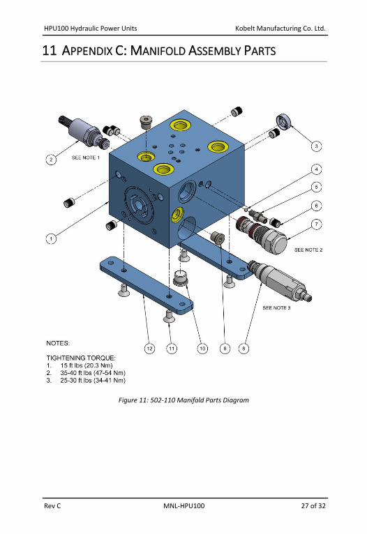
11 APPENDIX C: MANIFOLD ASSEMBLY PARTS
Figure 11: 502-110 Manifold Parts Diagram
HPU100 Hydraulic Power Units Kobelt Manufacturing Co. Ltd.
Rev C MNL-HPU100 28 of 32
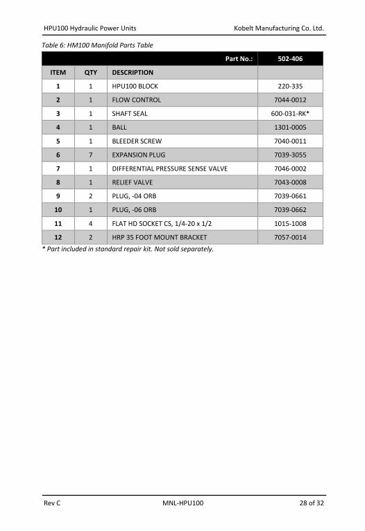
Table 6: HM100 Manifold Parts Table
Part No.: 502-406
ITEM QTY DESCRIPTION
1 1 HPU100 BLOCK 220-335
2 1 FLOW CONTROL 7044-0012
3 1 SHAFT SEAL 600-031-RK*
4 1 BALL 1301-0005
5 1 BLEEDER SCREW 7040-0011
6 7 EXPANSION PLUG 7039-3055
7 1 DIFFERENTIAL PRESSURE SENSE VALVE 7046-0002
8 1 RELIEF VALVE 7043-0008
9 2 PLUG, -04 ORB 7039-0661
10 1 PLUG, -06 ORB 7039-0662
11 4 FLAT HD SOCKET CS, 1/4-20 x 1/2 1015-1008
12 2 HRP 35 FOOT MOUNT BRACKET 7057-0014
* Part included in standard repair kit. Not sold separately.
HPU100 Hydraulic Power Units Kobelt Manufacturing Co. Ltd.
Rev C MNL-HPU100 29 of 32
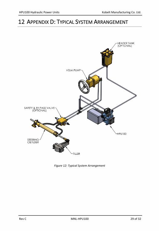
12 APPENDIX D: TYPICAL SYSTEM ARRANGEMENT
Figure 12: Typical System Arrangement
HPU100 Hydraulic Power Units Kobelt Manufacturing Co. Ltd.
Rev C MNL-HPU100 30 of 32
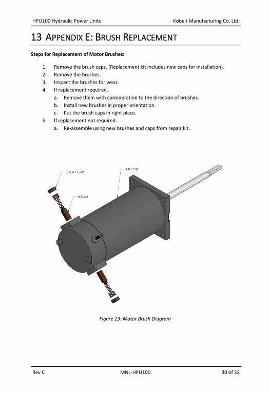
13 APPENDIX E: BRUSH REPLACEMENT
Steps for Replacement of Motor Brushes:
1. Remove the brush caps. (Replacement kit includes new caps for installation).
2. Remove the brushes.
3. Inspect the brushes for wear.
4. If replacement required.
a. Remove them with consideration to the direction of brushes.
b. Install new brushes in proper orientation.
c. Put the brush caps in right place.
5. If replacement not required.
a. Re-assemble using new brushes and caps from repair kit.
Figure 13: Motor Brush Diagram
HPU100 Hydraulic Power Units Kobelt Manufacturing Co. Ltd.
Rev C MNL-HPU100 31 of 32
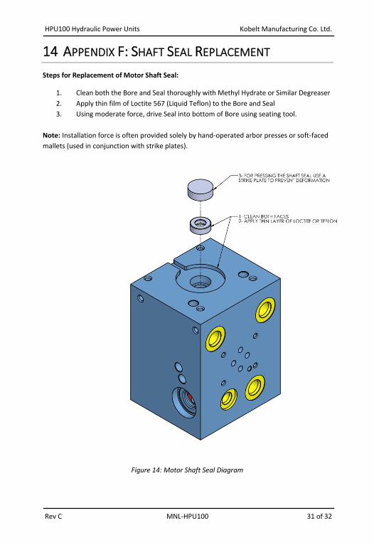
14 APPENDIX F: SHAFT SEAL REPLACEMENT
Steps for Replacement of Motor Shaft Seal:
1. Clean both the Bore and Seal thoroughly with Methyl Hydrate or Similar Degreaser
2. Apply thin film of Loctite 567 (Liquid Teflon) to the Bore and Seal
3. Using moderate force, drive Seal into bottom of Bore using seating tool.
Note: Installation force is often provided solely by hand-operated arbor presses or soft-faced
mallets (used in conjunction with strike plates).
Figure 14: Motor Shaft Seal Diagram

Kobelt Manufacturing Co. Ltd.
8238 129th Street Surrey, British Columbia,
Canada, V3W 0A6
Sales Tel: +1-604-572-3935 Fax: +1-604-590-8313 Email: [email protected] Website: www.kobelt.com
Made in Canada / Printed in Canada