knowledge engineering techniques for the translation of process...
TRANSCRIPT

Knowledge Engineering Techniques for the Translation ofProcess Models into Temporal Hierarchical Planning and
Scheduling Domains
A thesis submitted in fulfilment of the requirements
for the degree of Doctor of Computer Engineering
Universidad de Granada, July 2011
Arturo González Ferrer
Supervisors:Juan Fernández Olivares, Luis Castillo Vidal
Escuela Técnica Superior de Ingeniería Informática y Telecomunicaciones
University of Granada
Spain

Editor: Editorial de la Universidad de GranadaAutor: Arturo González FerrerD.L.: GR 966-2012ISBN: 978-84-694-9410-3

ii
The most important aim of Knowledge Engineering isturning the process of constructing Knowledge Based Systems
from an Art into an Engineering Discipline
[Studer, Benjamins, & Fensel, 1998]

iii
Resumen
La tecnología de Planning & Scheduling Inteligente (AI P&S) se ha enfrentado desde sus inicios a unaimperiosa necesidad de mejorar el soporte para la utilización e integración de tecnologías tradicionalesde desarrollo software, o cuando menos, de acercarse a los usuarios del dominio de aplicación dondese quieren integrar componentes basados en esta tecnología. Esto es debido a que el desarrollo decomponentes basados en AI P&S, tradicionalmente ha seguido un camino propio, apartado de losmétodos tradicionales de desarrollo software, utilizando lenguajes y técnicas desarrolladas ad-hocpara el modelado de escenarios reales complejos. Además, en estos escenarios típicamente se necesitamanejar información como acciones, estados, restricciones sobre tiempo y recursos, cuya representa-ción no es trivial, ni tan usual en otras áreas de Ciencias de la Computación.
Es evidente que, para conseguir este fin, se necesita desarrollar técnicas de Ingeniería del Conoci-miento (Knowledge Engineering), que permitan abordar las fases de Adquisición y Representación deconocimiento experto, de un modo similar a como se lleva a cabo en otras áreas de la Computación,bien mediante técnicas tradicionales de diseño software, bien mediante métodos y lenguajes utilizadosen el campo de aplicación específico. El principal objetivo de este fin es sin duda simplificar la tarea delos ingenieros, a la vez que su interacción con el experto, a la hora de modelar problemas reales, permi-tiendo aumentar la reutilización, y facilitando al mismo tiempo el mantenimiento de los componentessoftware basados en AI P&S. En este sentido, esta tesis está alineada con los objetivos comentados,y su fin principal es el desarrollo de técnicas de Ingeniería del Conocimiento para automatizar latraducción de modelos de procesos para expresarlos en términos de una representación basada en elparadigma de planificación inteligente conocido como HTN (Hierarchical Task Network).
Concretamente, la tesis está enfocada en el estudio de dos dominios de aplicación muy concretos:los modelos de procesos de negocio expresados mediante la notación BPMN, y los modelos de pro-cesos clínicos expresados mediante Guías de Práctica Clínicas (CPGs). En el primer caso, se estudiarála transformación de patrones de flujo de control comunmente encontrados en dichos modelos, asícomo la representación de restricciones sobre recursos. En el segundo caso, se amplia el estudioprevio con idea de poder traducir restricciones temporales complejas (ej. sincronizaciones y ciclos),fundamentales para la representación de modelos de procesos en el ámbito clínico.
Los resultados de la investigación llevada a cabo permiten, por un lado, mejorar la capacidad dedefinir, de una manera sencilla, modelos y dominios de planificación a partir de notaciones estándarpara el modelado de procesos en los campos de aplicación mencionados. Por otro lado, introducenfuncionalidades de ayuda a la decisión en dichos dominios de aplicación. Esta última contribuciónpermite resolver problemas de difícil solución hasta ahora en ambos dominios, como son la generaciónautomatizada de planes de trabajo en procesos organizativos o la generación automática de planes detratamiento personalizados para pacientes, añadiendo valor a la tecnología de Planificación Inteligente.
iv
Abstract
Artificial Intelligent Planning & Scheduling technology (AI P&S) has confronted, from its verybeginning, the absolute necessity of improving the support for using and integrating traditional softwareengineering techniques, or at least, to get closer to users of the application domain where AI P&Scomponents want to be integrated. This is due to the fact that the development of components based onAI P&S, has traditionally used ad-hoc languages and techniques developed for the modelling of realcomplex scenarios, separated from traditional software development methods. Furthermore, in thesescenarios it is typically needed to manage information such as actions, states and constraints about timeand resources, using a representation that is nor trivial neither usual in other areas of Computer Science.
It is evident that, in order to achieve this aim, it is needed to develop Knowledge Engineeringtechniques that allow to accomplish the stages of expert knowledge acquisition and representation, in asimilar way to how it is carried out in other areas of Computer Science, either by means of traditionaltechniques for software design, or by means of methods and languages used on the specific applicationfield. This aims to simplify the task of engineers and the interaction with experts when modelingreal problems, allowing to improve the reuse, and facilitating at the same time the maintenance ofcomponents based on AI P&S techniques. In this sense, this dissertation is aligned with the abovementioned goals, and aims to develop Knowledge Engineering techniques to automatically carry outthe translation of process models, in order to express them in terms of a representation based on theHTN (Hierarchical Task Network) planning paradigm.
Concretely, the dissertation is focused on the study of two specific application domains: businessprocess models expressed by means of the BPMN notation, and clinical processes expressed by meansof Clinical Practice Guidelines (CPGs). In the former, it is studied how to carry out the translationof control-flow patterns commonly found on such models, as well as the representation of resourceconstraints. On the latter, the previous work is extended, in order to translate complex temporalconstraints (e.g. temporal annotations, synchronizations and cycles) that are fundamental to representprocess models in the clinical domain.
The results of this research allow, on the one hand, to improve the capability to define planningdomains models in a simple way, starting from standard notations used for the process modeling in thementioned application fields. On the other hand, they introduce features for decision making supportin such application domains. This last contribution allows to solve problems difficult to solve so farin both domains, such as the automatic generation of working plans in organizative processes, or theautomatic generation of patient-tailored treatment plans, adding extra value to AI P&S technology.
Contents
List of Figures ix
List of Algorithms xi
List of Tables xiii
1 Introduction 11.1 Motivation . . . . . . . . . . . . . . . . . . . . . . . . . . . . . . . . . . . . . . . . 11.2 Aims and Goals . . . . . . . . . . . . . . . . . . . . . . . . . . . . . . . . . . . . . 31.3 Structure and Contributions . . . . . . . . . . . . . . . . . . . . . . . . . . . . . . . 41.4 Publications . . . . . . . . . . . . . . . . . . . . . . . . . . . . . . . . . . . . . . . 91.5 Evalution Reports from European Experts . . . . . . . . . . . . . . . . . . . . . . . 13
2 Knowledge Engineering for Planning and Scheduling 172.1 Introduction . . . . . . . . . . . . . . . . . . . . . . . . . . . . . . . . . . . . . . . 172.2 Planning and Scheduling Systems . . . . . . . . . . . . . . . . . . . . . . . . . . . 19
2.2.1 Action, Time and Resources . . . . . . . . . . . . . . . . . . . . . . . . . . 202.2.2 Planning Strategies . . . . . . . . . . . . . . . . . . . . . . . . . . . . . . . 21
2.2.2.1 Classical Approach . . . . . . . . . . . . . . . . . . . . . . . . . 212.2.2.2 Hierarchical Task Network Planning . . . . . . . . . . . . . . . . 22
2.2.3 Planning Languages . . . . . . . . . . . . . . . . . . . . . . . . . . . . . . 252.2.3.1 PDDL: Planning Domain Definition Language . . . . . . . . . . . 252.2.3.2 HPDL: A hierarchical extension of PDDL . . . . . . . . . . . . . 26
2.3 Recent Advances in Knowledge Engineering for P&S . . . . . . . . . . . . . . . . . 322.3.1 The Design Process for Planning Systems . . . . . . . . . . . . . . . . . . . 332.3.2 A review of most relevant KE tools . . . . . . . . . . . . . . . . . . . . . . 34
2.3.2.1 GIPO . . . . . . . . . . . . . . . . . . . . . . . . . . . . . . . . . 342.3.2.2 itSIMPLE . . . . . . . . . . . . . . . . . . . . . . . . . . . . . . 362.3.2.3 Automatic Semantic Web Services Composition . . . . . . . . . . 392.3.2.4 Ground Work: The Project ADAPTAPLAN . . . . . . . . . . . . 402.3.2.5 JABBAH and Asbru2HPDL . . . . . . . . . . . . . . . . . . . . . 45
vi CONTENTS
3 From Business Process Models to HTN Planning Domains 493.1 Introduction and Motivation . . . . . . . . . . . . . . . . . . . . . . . . . . . . . . 493.2 Technical Background . . . . . . . . . . . . . . . . . . . . . . . . . . . . . . . . . 51
3.2.1 BPMN and XPDL . . . . . . . . . . . . . . . . . . . . . . . . . . . . . . . 513.2.2 Structuredness and Workflow Patterns . . . . . . . . . . . . . . . . . . . . . 533.2.3 Hierarchical Task Network Planning Language . . . . . . . . . . . . . . . . 56
3.3 Methodology for the BPM-HTN translation . . . . . . . . . . . . . . . . . . . . . . 593.3.1 Mapping to a Graph Model . . . . . . . . . . . . . . . . . . . . . . . . . . . 59
3.3.1.1 Input process model requirements . . . . . . . . . . . . . . . . . . 603.3.2 Block Detection: Building a Tree Model . . . . . . . . . . . . . . . . . . . . 613.3.3 HTN-PDDL Code Generation . . . . . . . . . . . . . . . . . . . . . . . . . 63
3.4 Related work . . . . . . . . . . . . . . . . . . . . . . . . . . . . . . . . . . . . . . 683.5 Appendix I . . . . . . . . . . . . . . . . . . . . . . . . . . . . . . . . . . . . . . . 69
4 From Clinical Guidelines to Temporal HTN Planning Domains 734.1 Introduction . . . . . . . . . . . . . . . . . . . . . . . . . . . . . . . . . . . . . . . 73
4.1.1 Background and Motivation . . . . . . . . . . . . . . . . . . . . . . . . . . 734.1.2 Objective . . . . . . . . . . . . . . . . . . . . . . . . . . . . . . . . . . . . 75
4.2 Methods and Materials . . . . . . . . . . . . . . . . . . . . . . . . . . . . . . . . . 764.2.1 Overview of the approach . . . . . . . . . . . . . . . . . . . . . . . . . . . 764.2.2 Computer Interpretable Guideline languages: Asbru . . . . . . . . . . . . . 774.2.3 Hierarchical Task Network planning: HPDL . . . . . . . . . . . . . . . . . . 784.2.4 Comparison of both frameworks . . . . . . . . . . . . . . . . . . . . . . . . 78
4.3 Analysis of temporal knowledge . . . . . . . . . . . . . . . . . . . . . . . . . . . . 824.3.1 Time annotations . . . . . . . . . . . . . . . . . . . . . . . . . . . . . . . . 834.3.2 Time-annotated references to plan activations . . . . . . . . . . . . . . . . . 844.3.3 Cyclical time annotations . . . . . . . . . . . . . . . . . . . . . . . . . . . . 85
4.4 Mapping Asbru to the HTN formalism . . . . . . . . . . . . . . . . . . . . . . . . . 874.4.1 Objects and Types . . . . . . . . . . . . . . . . . . . . . . . . . . . . . . . 874.4.2 Skeletal plans . . . . . . . . . . . . . . . . . . . . . . . . . . . . . . . . . . 874.4.3 Time annotations in plan activations . . . . . . . . . . . . . . . . . . . . . . 884.4.4 Cyclical Plans . . . . . . . . . . . . . . . . . . . . . . . . . . . . . . . . . 894.4.5 Generation of HPDL code . . . . . . . . . . . . . . . . . . . . . . . . . . . 91
4.5 Related Work . . . . . . . . . . . . . . . . . . . . . . . . . . . . . . . . . . . . . . 95
5 Results 995.1 Mapping BPM models to HTN domains . . . . . . . . . . . . . . . . . . . . . . . . 99
5.1.1 The JABBAH framework . . . . . . . . . . . . . . . . . . . . . . . . . . . . 995.1.2 Experiments . . . . . . . . . . . . . . . . . . . . . . . . . . . . . . . . . . 1015.1.3 Findings . . . . . . . . . . . . . . . . . . . . . . . . . . . . . . . . . . . . 103
5.2 Automated generation of patient-tailored care pathways . . . . . . . . . . . . . . . . 1095.2.1 Context: the Hodgkin’s disease guideline . . . . . . . . . . . . . . . . . . . 1095.2.2 Experiments . . . . . . . . . . . . . . . . . . . . . . . . . . . . . . . . . . 1115.2.3 Discussion . . . . . . . . . . . . . . . . . . . . . . . . . . . . . . . . . . . 121

CONTENTS vii
6 Conclusions and Future Work 123
Bibliography 127

viii CONTENTS

List of Figures
2.1 The ’blocks world’ planning problem . . . . . . . . . . . . . . . . . . . . . . . . . . 222.2 A rough outline of an HTN planning algorithm . . . . . . . . . . . . . . . . . . . . 242.3 The basics of HTN planning domains in the HPDL language . . . . . . . . . . . . . 282.4 The multiple task ordering schemas provided by HPDL . . . . . . . . . . . . . . . . 282.5 Encoding Allen’s relations by means of temporal landmarks . . . . . . . . . . . . . 312.6 GIPO Architecture . . . . . . . . . . . . . . . . . . . . . . . . . . . . . . . . . . . 342.7 Modeling with UML Class Diagram in itSIMPLE . . . . . . . . . . . . . . . . . . . 372.8 Architecture of the ADAPTAPLAN project . . . . . . . . . . . . . . . . . . . . . . 422.9 A possible labelling of learning objects . . . . . . . . . . . . . . . . . . . . . . . . . 442.10 A possible learning path obtained for jack in ADAPTAPLAN . . . . . . . . . . . . . 452.11 Leveraging the BPM life-cycle with a new AI planning stage . . . . . . . . . . . . . 46
3.1 Frequency distribution of BPMN elements usage . . . . . . . . . . . . . . . . . . . 523.2 A BPMN model describing an e-learning course development process . . . . . . . . 543.3 HPDL code for a split-join workflow pattern . . . . . . . . . . . . . . . . . . . . . . 573.4 Different stages of the BPMN to HPDL translation process . . . . . . . . . . . . . . 573.5 Branch-water mark procedure and workflow pattern detection . . . . . . . . . . . . . 613.6 Identifying Workflow Patterns in the Nested Process Model . . . . . . . . . . . . . . 623.7 Parallel Workflow Patterns: Split-Join and exclusive-OR . . . . . . . . . . . . . . . 66
4.1 Methodology life-cycle for translation of Clinical Guidelines into HTN Domains . . 774.2 Traditional use of Asbru in high-frequency domains like ICU’s . . . . . . . . . . . . 804.3 Traditional use of Asbru in high-frequency domains like ICU’s . . . . . . . . . . . . 804.4 Similarities between the structure of Asbru skeletal plans and HPDL task network . . 824.5 Time annotations in the Asbru language . . . . . . . . . . . . . . . . . . . . . . . . 834.6 Temporal Landmarks in the HPDL language . . . . . . . . . . . . . . . . . . . . . . 864.7 Graphical representation of the synchronization between chemotherapy cycles . . . . 884.8 Description of delays in Asbru and HPDL languages . . . . . . . . . . . . . . . . . 89
5.1 Some screenshots of JABBAH in action . . . . . . . . . . . . . . . . . . . . . . . . 1005.2 Outline of the patient admission scenario process model (part 1) . . . . . . . . . . . 104

x LIST OF FIGURES
5.3 Outline of the patient admission scenario process model (part 2) . . . . . . . . . . . 1055.4 Visualization of the output plan as a Gantt Diagram . . . . . . . . . . . . . . . . . . 1065.5 Workflow Schema of the Hodgkin’s Disease Clinical Protocol . . . . . . . . . . . . 1105.6 Architecture for expressing clinical protocols in terms of HTNs in order to develop a
AI-based CDSS . . . . . . . . . . . . . . . . . . . . . . . . . . . . . . . . . . . . . 1115.7 Modeling the Hodgkin disease protocol in Asbru by using the DELT/A tool. On the
left side, you can see the original protocol document, and on the right side you canmodel in Asbru and link at the same time parts of the XML model with the documenton the left . . . . . . . . . . . . . . . . . . . . . . . . . . . . . . . . . . . . . . . . 113
5.8 Execution of Care Pathways in a BPM suite . . . . . . . . . . . . . . . . . . . . . . 119

List of Algorithms
1 General Overview . . . . . . . . . . . . . . . . . . . . . . . . . . . . . . . . . . . . 582 Generate Durative Actions from Activities . . . . . . . . . . . . . . . . . . . . . . . 643 Generate Tasks from Serial Blocks . . . . . . . . . . . . . . . . . . . . . . . . . . . 654 Generation of Tasks for Split-Join Blocks . . . . . . . . . . . . . . . . . . . . . . . 665 Generation of Tasks for XOR blocks . . . . . . . . . . . . . . . . . . . . . . . . . . 676 Mapping Asbru models to HPDL Domains . . . . . . . . . . . . . . . . . . . . . . . 92

xii LIST OF ALGORITHMS

List of Tables
4.1 Comparison of both frameworks . . . . . . . . . . . . . . . . . . . . . . . . . . . . 79
5.1 BPMN elements and the corresponding HTN elements generated for both models . . 1035.2 Different plan instances and allocation for e-health process according to different input
values . . . . . . . . . . . . . . . . . . . . . . . . . . . . . . . . . . . . . . . . . . 1085.3 Planner text output showing part of an automatically generated Care Pathway . . . . 1185.4 Different patterns in the Hodgkin protocol that are correctly managed by the architecture120

xiv LIST OF TABLES

Chapter 1Introduction
1.1 Motivation
Hierarchical Task Networks (HTN) AI planning and scheduling (P&S) [Castillo et al., 2006; Erol et al.,
1994b; Nau et al., 2003; Sacerdoti, 1975] is a technology developed and introduced in the last three
decades for the development of intelligent systems that, given its high expressivity to represent complex
real problems, has shown to be very helpful for solving common problems in the area of Artificial
Intelligence. Roughly speaking, it is an automated planning strategy that supports the modeling of
planning domains in terms of a compositional hierarchy of tasks, representing compound and primitive
tasks at different levels of abstraction. HTN planning has been useful to cope with different real
problems, mostly directed to provide automatic decision-making support for human-centric tasks, but
also used in order to assist in more general areas of computer-aided support, i.e in typical tasks where
planning and scheduling are needed, like manufacturing, robotics, aerospace applications, etc.
Nonetheless, it continues being a cumbersome technology for traditional knowledge engineers that are
not used to the HTN technology or to its formalization procedure (e.g. formulating complex planning
domain models with first-order logic languages like PDDL [Fox & Long, 2003] or a extension of it
[Castillo et al., 2006]). The planning community agree that this issue arises from the difficulties that
the acquisition of expert knowledge entails, but also from the mechanisms used by standard planning
languages and techniques in order to model real problems. These mechanisms clearly diverge from
traditional software engineering techniques, and not enough facilities and methodologies have been
developed in order to bridge the gap between the modeling of expert knowledge and the representation
in terms of planning domains.

2 Introduction
Thus, this has become a great obstacle for the development and integration of real planning systems. It
is clear that this obstacle is a great inconvenient for a very valuable technology like HTN planning to be
introduced broadly in the industry. As a matter of fact, this feeling is shared by most researchers in the
area of planning, mostly by those involved in the area of Knowledge Engineering for P&S. Concretely,
some research challenges were recently identified in this area, stablishing where most of the efforts
should be placed, as it was described in the technological roadmap of the PLANET European Network
of Excellence in AI Planning [Biundo et al., 2003].
A set of technological challenges were identified in this roadmap in order to bring AI planning
technology closer to other areas of software development or, in other words, to make the most of
common software engineering techniques and standard notations and languages, so that they can be
used in order to easily develop planning systems. Generally speaking, new and better knowledge
acquisition and knowledge engineering methods are needed, either to develop systems following a
process that is more aligned with common software engineering, or by taking a smarter approach that
aims to reuse languages and notations that are standard in the application domain. This way, we aim to
reduce the effort that need to be made by engineers by means of translation tools that automatically
convert the knowledge, from formalisms standard in the application domain, to formalisms used for
planning domain modeling. A variety of software components and techniques have been developed in
the last decade to cope with this problem [Vaquero et al., 2011].
For example, an initial work [Castillo et al., 2010, 2007b], that indeed motivated the development of
this dissertation, presented an approach to automatically extract a fully operational HTN planning
domain and problem from a standard Learning Objects Repository without requiring the intervention
of any planning expert. The main objective of this contribution was to enable an easier adoption of this
technology in the e-learning field, for the automated generation of customized learning paths, tailored
to students needs, but focusing on using knowledge available in a format that is initially far from the
planning formalisms (but that is a standard representation in the area of e-learning).
Starting from some of the issues identified in the PLANET Roadmap, and on the basis of the ground-
work carried out in [Castillo et al., 2010, 2007b], this dissertation take a step forward in (re)using
modern software engineering techniques for the modeling and formulation of planning problems, tack-
ling some of the challenges previously identified. So, it aims to facilitate the process of acquisition,elicitation and representation of expert planning knowledge (e.g. actions, time and resources),starting from a modeling stage that is carried out with techniques, tools and formalisms thatare either usually known by traditional knowledge engineers, or that are commonly used in thespecific application domain. Concretely, standard notations for the definition of process models
(either in the business scope or in the healthcare domain) are reused for the development of planning
systems. Next section describes the concrete aims and goals pursued in the dissertation.
1.2 Aims and Goals 3
1.2 Aims and Goals
The main aim of this PhD dissertation is to develop methods and techniques for easing the knowledge
elicitation process (i.e. acquiring knowledge from human experts), so that this knowledge can be easily
managed and translated, in order to automatically generate a corresponding HTN planning domain.
This methodology could serve as a base to facilitate the development of planning systems, or P&S
components that will be part of a more general software system. Thus, the challenge of knowledge
acquisition and automatic formulation of AI planning domains is addressed from two different, but
related, perspectives.
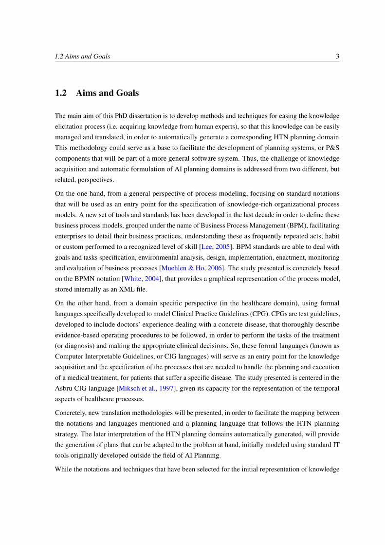
On the one hand, from a general perspective of process modeling, focusing on standard notations
that will be used as an entry point for the specification of knowledge-rich organizational process
models. A new set of tools and standards has been developed in the last decade in order to define these
business process models, grouped under the name of Business Process Management (BPM), facilitating
enterprises to detail their business practices, understanding these as frequently repeated acts, habit
or custom performed to a recognized level of skill [Lee, 2005]. BPM standards are able to deal with
goals and tasks specification, environmental analysis, design, implementation, enactment, monitoring
and evaluation of business processes [Muehlen & Ho, 2006]. The study presented is concretely based
on the BPMN notation [White, 2004], that provides a graphical representation of the process model,
stored internally as an XML file.
On the other hand, from a domain specific perspective (in the healthcare domain), using formal
languages specifically developed to model Clinical Practice Guidelines (CPG). CPGs are text guidelines,
developed to include doctors’ experience dealing with a concrete disease, that thoroughly describe
evidence-based operating procedures to be followed, in order to perform the tasks of the treatment
(or diagnosis) and making the appropriate clinical decisions. So, these formal languages (known as
Computer Interpretable Guidelines, or CIG languages) will serve as an entry point for the knowledge
acquisition and the specification of the processes that are needed to handle the planning and execution
of a medical treatment, for patients that suffer a specific disease. The study presented is centered in the
Asbru CIG language [Miksch et al., 1997], given its capacity for the representation of the temporal
aspects of healthcare processes.
Concretely, new translation methodologies will be presented, in order to facilitate the mapping between
the notations and languages mentioned and a planning language that follows the HTN planning
strategy. The later interpretation of the HTN planning domains automatically generated, will provide
the generation of plans that can be adapted to the problem at hand, initially modeled using standard IT
tools originally developed outside the field of AI Planning.
While the notations and techniques that have been selected for the initial representation of knowledge

4 Introduction
could seem very different at first, both BPM standard notations and CIG formal languages have a
lot of commonalities. As a matter of fact, they have been compared in the literature focusing on
the capabilities that both present for the representation of workflow patterns [Mulyar et al., 2007;
van der Aalst et al., 2003]. Furthermore, Healthcare Delivery Organizations (HDOs) are facing the
challenge of delivering personalized services to their patients in a cost-effective and efficient manner.
This, in turn, requires advanced IT support for healthcare processes covering both organizational
procedures and knowledge-intensive, dynamic treatment processes [Reichert, 2011; Terenziani, 2010].
Hence, BPM is perfectly suitable for this aim, and it has been used in the last decade for the develop-
ment of Clinical Decision Support Systems (CDSS) (e.g. [Huser et al., 2011; Quaglini et al., 2000]).
Furthermore, the yearly organization of different workshops and conferences to join both areas (e.g.
ProHealth)1 is a proof of that.
Therefore, the first part of this dissertation is focused on the representation of control-flow information
and resources with BPMN, while the second part takes one step forward on the representation of time-
related information with Asbru (given its higher expressivity for this issue than BPMN, and because
of the relevance that the representation of time has for the correct representation and management of
clinical protocols). Before that, Planning Systems and the problem of Knowledge Engineering for
Planning and Scheduling are introduced.
1.3 Structure and Contributions
This dissertation is structured in six chapters, including the current one, where the problem is briefly
introduced, and its aims and goals are described. This section details the structure and contributions of
this dissertation.
In Chapter 2 the problems usually confronted when developing AI P&S software systems are described,
and it is depicted how introducing Knowledge Engineering techniques could be helpful to overcome
these problems. Before deeping into that aspect, we include an introduction to the AI P&S technology,
describing the planning strategies and languages used in this dissertation. Then, a brief review about
recent lessons learned in the area of KE for P&S is given, also introducing the most relevant related
tools and techniques that have been developed recently for the task of knowledge elicitation and
formulation of planning domains. We finally describe the preliminary work in the field of e-learning
that partly motivated the main developments and advances presented in this dissertation. Chapters 3
and 4 are devoted to present the new Knowledge Engineering techniques developed.
1International Workshop on Process-oriented Information Systems in Healthcare

1.3 Structure and Contributions 5
Chapter 3 aims to describe how to extract HTN planning domains from process models that have been
specified through the use of the Business Process Modeling Notation [White, 2004]. This graphical
notation is usually included as part of bigger tools known as Business Process Management (BPM)
suites, used for the integration and automation of business processes. The developments of this
chapter entail an important contribution, given that BPM tools usually lacks of better support for
decision making capabilities, and more significantly, they are very neat and user-friendly tools for the
specification and later elicitation of knowledge about human-centric or machine-based processes. The
equivalences between Business Process Models and HTN planning domains are described, and the
notion of well-structuredness and workflow patterns for process models is introduced. Then, both a
methodology and a corresponding algorithm for the pattern-based translation of well-structured process
models into HTN domains are provided, focusing on the control-flow information and constraints
about resources.
Starting from the findings of Chapter 3, Chapter 4 takes one step forward on the representation and
translation of temporal patterns, something that was not done with BPMN due to its poor expressivity
for the representation of time-related information [Gagné & Trudel, 2009]. Therefore, this chapter
is focused in the specific domain of healthcare, where languages known as Computer Interpretable
Guidelines (CIG) were recently developed for the management of the multiple modeling aspects
needed in healthcare processes. A comparison of both representational languages, Asbru and HTN, is
described. Afterwards, an analysis of the temporal patterns that can be represented with the Asbru CIG
language is carried out, in order to later develop a mapping from an Asbru representation of clinical
protocols into corresponding HTN planning domains.
In order to illustrate the methodologies devepeloped, Chapter 5 is devoted to expose some real use
cases that were conducted, like the modeling through BPMN of the activities and processes that
are carried out within an e-learning center for the development of learning objects and courses, or
the modeling with Asbru of a clinical protocol to provide decision-making support for handling the
treatment of patients that suffer the Hodgkin’s disease. These scenarios are confronted and presented
taking into account the most usual requirements for the modeling and development of AI planning
systems, i.e. the modeling of actions, and constraints about time and resources.
Chapter 6 include the conclusions that were extracted from the results obtained, also identifying the
contributions that have been made in the area, and pointing to future developments that would be of
interest.
Some of the main contributions made by this dissertation are enumerated next:
1. Generally speaking, new ways of developing Intelligent Systems that provide support for decision
making, based on AI P&S techniques, are presented, focusing on the initial stage of elicitation

6 Introduction
and formulation of expert knowledge for AI planning problems. Thus, some contributions are
presented that fit within the area of Knowledge Engineering (KE), the goal of which is very
similar to that of Software Engineering: turning the process of constructing Knowledge Based
Systems from an art into an engineering discipline, an aim that must be achieved by developing
more methodological approaches [Studer et al., 1998].
2. The identification of the achievements recently made in the area of Knowledge Engineering for
Planning and Scheduling, and some of the remaining challenges where more effort could be
placed. Multiple Knowledge Engineering tools [Vaquero et al., 2011] (e.g. GIPO, ITSIMPLE
or PORSCE) are presented, and situated in order to understand where the research is being
directed and what pitfalls still need to be addressed. We include a brief description of the
initial work carried out in the e-learning domain [Castillo et al., 2010, 2007b; Morales et al.,
2008] for the automatic generation of customized learning paths. The JABBAH framework
[González-Ferrer et al., 2009], created by the author of this dissertation and winner of the 3rd
International Competition ICKEPS,2 and the Asbru2HPDL tool, are finally described.
3. The identification of similarities and equivalences between general process modeling notations
and HTN planning languages is presented [González-Ferrer et al., 2011a], since it is the first
step needed in order to automatize the elicitation and formulation of knowledge. Thus, it is
identified how to bridge the gap between common knowledge representation techniques in
the field of process modeling (i.e. BPMN) and the representation of AI planning problems.
Furthermore, the study of these similarities is also addressed for a domain specific language
(in the field of healthcare), comparing Computer Interpretable Guidelines with HTN planning
languages [González-Ferrer et al., 2011b].
This way, it is shown that some different, already existing knowledge representation techniques
for multiple real scenarios, can be reused in order to easily develop a P&S software component
without needing a completely new stage of knowledge representation. This allows to take a
step forward in addressing the big obstacle (and the costs associated) that traditionally was
to formulate AI planning domains from the scratch, in the context of a real scenario that may
already have associated standard ways of representing information.
4. The development of a Knowledge Engineering methodology to achieve a transformation from
well-structured Business Process Models to HTN planning domains [González-Ferrer et al.,
2011a], focusing on the representation of control-flow information and constraints about re-
sources. This is done in order to let the user to obtain a process plan automatically, respecting
2see website at http://kti.mff.cuni.cz/ bartak/ICKEPS2009/

1.3 Structure and Contributions 7
the constraints and control-flow information specified in the original process model. So, start-
ing from a well-structured BPMN process model, a knowledge acquisition stage is proposed
that allows to build up a corresponding nested process model following a hierarchical struc-
ture, i.e. a tree model. This tree model can be built by means of a graph reduction process
(by determining the most basic control flow patterns split-join, exclusive-OR and sequences
[González-Ferrer et al., 2008b]) and the subsequent tree expansion of this reduced graph. The
reason for this reduction-expansion process is that all these patterns can be easily represented
with our HTN extension of PDDL (HPDL [Castillo et al., 2006]).
Once the hierarchical planning domain and problem have been generated, the IACTIVE in-
telligent planner3 can interpret them, obtaining a corresponding plan that respects all the
order, resource, and control flow constraints stablished in the original process model. A
translation of this plan into a representation understandable by a BPM engine, allows the
process plan automatically obtained to be ubiquitously executed and monitored by the par-
ticipants involved [Fdez-Olivares et al., 2010b]. In this sense, it is presented a proposal that
enhance the current BPM life-cycle [Fdez-Olivares et al., 2010a] in order to support smart pro-
cesses through the development of Knowledge Engineering and intelligent planning techniques
[González-Ferrer et al., 2010].
5. The development of a methodology to develop transformations from Computer Interpretable
Guidelines to HTN planning domains [González-Ferrer et al., 2011b], focusing on the repres-
entation of temporal patterns usually found on clinical protocols. We present an AI-based
knowledge engineering methodology to develop, model, and operationalize care pathways, thus
providing an evidence-based Decision Support System for oncology treatments. This is carried
out starting from the medical knowledge existing in a previously defined Computer Interpretable
Guideline, represented in the Asbru language.
Thus, by means of a translation into an HTN planning domain, and through deliberative reason-
ing, a solution for the sequencing and scheduling of the tasks involved in the specific protocol
is presented, developing a patient-tailored computerized care pathway that respects the patient
profile, the available resources and the protocol temporal patterns. Specifically, it is shown how
to deal with the patterns usually managed in these clinical protocols, i.e. multiple task ordering
schemas, delays, synchronizations and cycles. The advancements developed allow an intelligent
planner to manage and interpret the doctors’ expert knowledge, in order to generate customized
treatment plans for different patient profiles. This enables a healthcare process that is:
3this planner has been used in multiple real application domains [Castillo et al., 2008; Fdez-Olivares et al., 2006;Palao et al., 2011], and also in the e-learning domain [Castillo et al., 2010], that will be used, together with the e-healthdomain [González-Ferrer et al., 2011b], as case studies of this dissertation

8 Introduction
• safer (the plan automatically generated is aligned with the original protocol),
• efficient (it reduces costs, synchronizing patients needs with availability of resources),
• customized (the treatment plan is adapted to every existing patient profile) and
• high-quality (the patient’s stay time in hospital is also adjusted to real needs).
A similar strategy is provided for the ubiquitous execution and monitoring of the generated
patient-tailored care pathway, by means of a translation of it back into a representation that can
be interpreted by a BPM runtime engine.
6. Starting from the theoretical achievements made, it is also shown the real application of the
contributions to different real scenarios in the fields of e-learning and healthcare.
i) Use cases for the translation of organizational BPM models [González-Ferrer et al., 2011a].
The first scenario [González-Ferrer et al., 2008a], represents how to develop and deploy a
specific course within the e-learning center at the University of Granada. Having an incoming
course request, as well as some available workers with different capabilities each, a plan instance
can be obtained providing the managers information about the workers allocation and the make-
span of the whole course development, helping to do decision-making upon the course request.
The second scenario represents a general care-process starting from a patient entry into a hospital
and finishing when the health insurance billing for this patient takes place.
Both scenarios aim to cover the following challenges: 1) check that a corresponding HTN
representation exists for process models that include a combination of (possibly nested) workflow
patterns, 2) find a plan instance that keeps the order constraints associated to those workflow
patterns, 3) check that the interpretation of the same HTN domain can find different plan
instances for different combinations of input parameters (i.e. decision gateways values), 4) show
that both planning (find the activities that form part of the plan) and scheduling (determine a
task ordering that respect time constraints, assigning also resources to activities) are needed in
order to find a situated plan.
ii) Use case for the translation of Clinical Guidelines [González-Ferrer et al., 2011b]. It is
described how to automatically generate an HTN representation of a specific oncology protocol
(the one for the Hodgkin’s disease). This is carried out starting from the corresponding repres-
entation of the protocol in the Asbru language. A patient-centered care pathway may therefore
be generated for a specific patient profile and different resources, offering decision support
capabilities to the doctors in a real scenario.

1.4 Publications 9
1.4 Publications
In this subsection are enumerated the publications in International Workshops, Conferences and
Journals that were carried out since the beginning of my research, in order to support the validation of
the scientific quality of this dissertation4.
1. Luis Castillo, Lluvia Morales, Arturo González-Ferrer,Juan Fdez-Olivares, Óscar García-Pérez. "Knowledge en-gineering and planning for the automated syndissertation ofcustomized learning designs". Current topics in ArtificialIntelligence (CAEPIA 2007). Springer LNAI Vol. 4788,2007.
2. Lluvia Morales, Luis Castillo, Juan Fdez-Olivares, Ar-turo González-Ferrer. "Automatic Generation of User Adap-ted Learning Designs: An AI-Planning Proposal". AdaptiveHypermedia and Adaptive Web-Based Systems (AH2008)Springer, LNCS Vol. 5149, 2008.
4Publication n. 6 obtained the Award of Excellence in the 3rd ICKEPS Competition 2009

10 Introduction
3. Arturo González-Ferrer, Luis Castillo, Juan Fdez-Olivares,Lluvia Morales. "Towards the Use of XPDL as Planningand Scheduling Modeling Tool: the Workflow Patterns Ap-proach". Advances in Artificial Intelligence (IBERAMIA2008) Springer LNAI Vol. 5290, 2008.
4. Arturo González-Ferrer, Luis Castillo, Juan Fdez-Olivares,Lluvia Morales. Workflow Planning for E-learning CenterManagement. 8th IEEE International Conference on Ad-vanced Learning Technologies (ICALT), IEEE ComputerSociety Press, 2008.
6. Arturo González-Ferrer, Juan Fdez-Olivares, LuisCastillo."JABBAH: A Java Application Framework for theTranslation Between Business Process Models and HTN".3rd International Competition on Knowledge Engineer-ing for Planning ICKEPS, Thesaloniki, Greece, AAAIPress, 2009.
7. Luis Castillo, Lluvia Morales, Arturo González-Ferrer,Juan Fdez-Olivares, Daniel Borrajo, Eva Onaindía. "Auto-matic generation of temporal planning domains for e-learningproblems". Journal of Scheduling, (ISSN: 1094-6136),2009/2010.

1.4 Publications 11
8. Juan Fdez-Olivares, Arturo González-Ferrer, InmaculadaSánchez-Garzón, Luis Castillo. "Using Knowledge Engineer-ing for Planning Techniques to leverage the BPM life-cycle fordynamic and adaptive processes". ICAPS 2010 Workshopon Knowledge Engineering for Planning and Scheduling(KEPS 2010). Toronto, Canada, 2010.
9. Juan Fdez-Olivares, Inmaculada Sánchez-Garzón, ArturoGonzález-Ferrer, Luis Castillo. "Integrating plans into BPMtechnologies for Human-Centric Process Execution". ICAPS2010 Workshop on Knowledge Engineering for Planningand Scheduling (KEPS 2010). Toronto, Canada. 2010.
10. Arturo González Ferrer, Juan Fdez-Olivares, InmaculadaSánchez-Garzón and Luis Castillo. "Smart Process Manage-ment: Automated Generation of Adaptive Cases based onIntelligent Planning Technologies". Proceedings of the 8thBPM Conference, Demonstration Track, Hoboken, USA,September 14-16, 2010, Vol. 615 CEUR-WS.org. 2010.

12 Introduction
11. Arturo González Ferrer, Juan Fdez-Olivares and LuisCastillo. "From Business Process Models to Hierarchical TaskNetwork Planning Domains". The Knowledge EngineeringReview, Cambridge Journals 2011. Accepted for Publication.
12. Arturo González Ferrer, Annette Ten Teije, Juan Fdez-Olivares, Krystyna Millian. "Careflow Planning: From Time-annotated Clinical Guidelines to Temporal Hierarchical TaskNetworks". 13th Conference in Artificial Intelligence inMedicine Europe, Springer, LNCS Vol. 6747. Acceptedfor Publication.
13. Juan Fdez-Olivares, Inmaculada Sánchez-Garzón, ArturoGonzález-Ferrer, Juan A. Cózar, Ana Fdez-Teijeiro, Manuel R.Cabello, and Luis Castillo. "Task Network based modeling,dynamic generation and adaptive execution of patient-tailoredtreatment plans based on Smart Process Management tech-nologies". Workshop in Knowledge Representation forHealth Care, Springer, LNCS Vol. TBD. Accepted for Pub-lication.

1.5 Evalution Reports from European Experts 13
1.5 Evalution Reports from European Experts
We include here some evaluation reports that were made by experts in the fields of Knowledge Engin-
eering for Planning and Scheduling (Roman Bartak and Lee McCluskey) or Knowledge Representation
and Reasoning in Medical Informatics (Annette ten Teije).
To whom it may concern
Prague, June 28, 2011
Evaluation Report on overview of PhD Thesis “Knowledge Engineering Techniques for the Translation of Process Models into Temporal Hierarchical Planning and Scheduling Domains” being prepared by Arturo Gonzáles-Ferrer at University of Granada The thesis under preparation deals with a very hot topic of knowledge engineering for planning and scheduling that can characterized as a bridge between real-world applications and planning and scheduling (P&S) technology. This area was underestimated in past where the focus of P&S community was mainly on solving techniques. As the solving technology advanced there became an immediate need to prepare data and right models for the solvers to allow their better exploitation in real-world problems. This is the area where the thesis advances the state of the art.
I know the work of Arturo Gonzáles-Ferrer mainly through his contributions to KEPS workshops and ICKEPS competitions that I co-organized and from ICAPS conferences. In particular, I would highlight his achievements in the area of formulation of e-learning problems as planning problems and in translation of business process models to HTN (Hierarchical Task Networks) formalism. This later work was implemented in the system JABBAH that was awarded at ICKEPS 2009 – International Competition on Knowledge Engineering for Planning and Scheduling mainly for considerable potential impact outside the planning community. I count these contributions as very important as they are giving practical examples of bridging real-world problems with academic research in the area of automated planning and they are good representatives of the novel area of knowledge engineering for P&S. The results were published at conference proceedings and respected international journals which justifies their importance in the research community.
I am convinced that Arturo Gonzáles-Ferrer achieved interesting and important results and that his PhD thesis is prepared for defense act. I have no hesitation in recommending this work for obtaining the European Doctorate.
Roman Barták Associate Professor of Computer Science Head of Department of Theoretical Computer Science and Mathematical Logic
Department of Theoretical Computer
Science and Mathematical Logic Malostranské nám. 25, 118 00 Praha 1
phone: +420 22191 4242 fax: +420 22191 4323
e-mail: [email protected]

14 Introduction

1.5 Evalution Reports from European Experts 15

16 Introduction
Chapter 2Knowledge Engineering for Planning and
Scheduling
2.1 Introduction
AI Planning and Scheduling (AI P&S) [Ghallab et al., 2004] is a key enabling technology for intelligent
systems. It has been developed and matured over the last three decades and a great variety of planning
systems1 for solving real problems have successfully been employed, e.g. in space and robotics
[Muscettola et al., 1998], emergencies [de la Asunción et al., 2005; Fdez-Olivares et al., 2006], tour-
ism [Ambite et al., 2002; Castillo et al., 2008; Palao et al., 2011], software design [Díaz-Pace & Campo,
2008], industrial manufacturing [Ruml et al., 2005], military operations [Wilkins & Desimone, 1992],
etc.
While all these planning systems share multiples characteristics with common software, all of them
also include specific features (described in section 2.2.1) that have deviated their development from
traditional software engineering techniques. Concretely, functions supported by AI P&S software
include the acquisition, engineering, and validation of domain knowledge, or the generation, evaluation
and execution of knowledge-rich plans and schedules [Biundo et al., 2003]. However, Knowledge
Engineering for P&S has not yet reached the maturity of other traditional engineering areas, in order
to define a common design process for planning applications.
By its very nature, AI Planning is knowledge-based. So, in order to develop these systems, it is usually
1we will use the term "planning systems" to refer to AI P&S systems

18 Knowledge Engineering for Planning and Scheduling
needed to model the knowledge associated to a particular scenario in so-called planning domain
models, e.g. starting from interviews with experts in the application field on how they solve specific
tasks, and formulating these domains directly from the knowledge acquired. The main characteristic
of a planning domain model is that it is possible for an agent to use one to make rational deductions
about the domain it represents [Biundo et al., 2003]. However, the planning domain modeling phase
is far from being based on standard tools and knowledge representation methodologies commonly
found in the area of Software and Knowledge Engineering (e.g. the Unified Modelling Language
[Fowler & Scott, 1997] for data modelling or the Business Process Modelling Notation [White, 2004]
for a higher abstract specification of process models).
On the one hand, this fact difficults the development and integration of the multiple components that are
part of the general software system being created, specially those that are typically specific to AI P&S
(e.g. imagine a software system that has been designed with UML, but where a planning component
being introduced has to be modeled totally from the scratch). On the other hand, it introduces a
problem of duplicating efforts for tasks that are similar in the software design process, forgetting
completely about the software engineering common goal of developing reusable components.
The modeling of these scenarios in the area of P&S, is typically carried out by taking advantage of the
flexibility that declarative planning languages provide, by creating ad-hoc "mini-languages" adapted
to the problem at hand. This tend to be one of the main characteristics of declaratives languages
(e.g. languages that uses a syntax inspired by LISP, like PDDL, described in section 2.2.3) where, for
example, the definition of predicates and functions properly customized for the application domain,
may provide a great expressivity power to represent and reason about real world problems.
While the expressivity and flexibility of declarative planning languages has to be highlighted, and it is
indeed very helpful when dealing with the modeling of real problems, the direct formulation of planning
domain models is not trivial. Furthermore, its development is not envisioned at all for documenting
the design process. The lack of visual and user-friendly interfaces for the domain specification, or the
avoidance of standard procedures of software development, forces this modeling stage to diverge from
the common aims of Software and Knowledge Engineering for building, maintaining and developing
Knowledge Based Systems.
This deviation from traditional software engineering standards is known as a great problem for the
introduction of AI P&S techniques in a wide range of possible applications in industry. Actually, it is
sometimes necessary to duplicate the need for multiple different engineering experts for developing
component-based planning systems. On the one hand, experts are needed on languages and knowledge
engineering techniques commonly used by software architects (e.g. standard notations as UML, BPMN,
PSL, etc.) or even in Domain Specific Languages (DSL) (e.g. in the healthcare domain, computer
interpretable guideline languages [de Clercq et al., 2004; Peleg et al., 2003] like Asbru or PROforma

2.2 Planning and Scheduling Systems 19
are becoming standard representations for the development of Clinical Decision Support Systems). On
the other hand, experts on AI P&S languages and techniques are of course needed as well.
The three mentioned problems (the lack of user-friendly interfaces, the separation from the traditional
software design process, and the need for AI planning expertise) have been traditionally a difficulty
for the formulation of planning domain models and the introduction of P&S features in real industrial
applications. This occurs because this duplicate effort for the modeling of real scenarios is usually
not well accepted, given the cost associated to this re-specification, besides the additional cost of
integrating these planning components with different aligned software components that have been
developed using more traditional and standard software engineering tools and techniques.
Thereby, a new research area has recently arisen, focused on developing Knowledge Engineering
techniques for Planning and Scheduling systems, so that these two areas (KE and P&S) can bring
their development rules closer. Generally speaking, Knowledge Engineering in AI Planning has been
defined as the process that deals with the acquisition, validation and maintenance of planning domain
models, and with the selection and optimization of appropriate planning machinery to work on them
[Simpson & McCluskey, 2002].
This chapter is focused on showing the main recent advances on this field, in order to situate and later
introduce the advances in the area that have been developed and presented in this thesis. First, the main
characteristics of planning systems are described, in order to understand the common problems of
P&S development. Next section is devoted to review the common characteristics of planning systems,
the planning paradigms that are either used or commented throughout this dissertation, and it also
describes in detail the planning languages related to those AI planning strategies.
2.2 Planning and Scheduling Systems
Automated Planning and Scheduling is a branch of Artificial Intelligence that concerns the realization
of strategies or action sequences, typically for execution by intelligent agents, or to be carried out by
humans in a timely manner. Professor Austin Tate offered the next definition in the MIT Encyclopedia
of Cognitive Science: "Planning is the process of generating (possibly partial) representations of future
behavior prior to the use of such plans to constrain or control that behavior. The outcome is usually a
set of actions, with temporal and other constraints on them, for execution by some agent or agents.
As a core aspect of human intelligence, planning has been studied since the earliest days of AI and
cognitive science. Planning research has led to many useful tools for real-world applications, and has
yielded significant insights into the organization of behavior and the nature of reasoning about actions."
Thus, in order to develop AI planning systems, planning algorithms take a description of the current

20 Knowledge Engineering for Planning and Scheduling
state of the world, a goal and a set of activities as input. The goal constitutes the desired state of the
world. There are defined a set of activities to transform the world from its actual state to the goal. An
activity is a piece of work that forms one logical step within a process. The conditions under which an
activity can be executed are called preconditions and its impact on the state of the world are called
effects. Finally, the description of this set of actions and their ordering (the process definition) is the
output of the planning algorithm [Schuschel & Weske, 2003]. These are the main aspects of planning
problems, nonetheless, even more complexity can be usually found when dealing with real planning
scenarios, as shown next.
2.2.1 Action, Time and Resources
Finding a sequence of actions that changes an initial world state into a different goal state is the main
challenge addressed by P&S systems. Even the most simple problems of this kind can have huge
search spaces, and in the worst case the complexity of classical planning is quite high, varying from
constant time to EXPSPACE-complete, depending on the representation used and the restrictions made
(see [Ghallab et al., 2004, section 3.4]). Furthermore, tackling real-world planning problems often
requires considering various types of constraints, which can range from simple numerical comparators
to complex constraints associated to time and resources [Nareyek et al., 2005].
The management of time and resources within AI P&S is very recent. Concretely, the first formal
definition of a temporal extension for the well-known PDDL planning language was introduced in
[Fox & Long, 2003]. Many problems consist only of simple temporal constraints. Examples of such
constraints are absolute time limits or deadlines (e.g. finish the activity by 10th March) or relative
constraints (e.g. the action of administering a specific drug in a patient treatment must last more than
10 minutes and less than half an hour). Moreover, temporal reasoning can become even harder when
resource constraints are mixed with time constraints. For example, the previous example of drug
administration, must be carried out by a specialist (resource) that is only available within a temporal
interval, e.g. its personal work schedule.
While reasoning about time and resources is relatively new to AI Planning and Scheduling, where fast
algorithms have been developed in the last decade, the development of representation schemes for
introducing knowledge about such constraints in real scenarios is a big issue as well, and there is still a
long way to go. Note that this knowledge is particularly interesting in P&S problems, but it could be
not so usual in other scenarios, modeled and managed through traditional software engineering tools.
Thus, new methods for knowledge acquisition and representation must be developed in order to easily
manage this information for achieving a tightly coupled integration into component-based planning
systems.

2.2 Planning and Scheduling Systems 21
This is one of the main research goals pursued within this thesis, and generally in the newly arisen
area of Knowledge Engineering for P&S. As previously commented, we have focused concretely in
studying how to reuse standard process modeling tools and notations, identifying the equivalences and
similarities with a concrete AI planning representation model (HTN), and stablishing the cornerstone
for advancing in the management of the knowledge needed for modeling P&S problems, starting from
either general or domain-specific tools and languages.
The following section is devoted to give more details about different AI planning strategies that are of
interest in this dissertation.
2.2.2 Planning Strategies
While planning systems address the problems described previously, different planning strategies have
been developed for representing and reasoning about these scenarios. In this section, the multiple
planning strategies that are mentioned and used through out this thesis are described. Particularly, the
HTN planning paradigm is fully detailed, since it has been the main paradigm used for the research
work presented.
2.2.2.1 Classical Approach
The basic principle of Classical Planning, also commonly known as STRIPS or STRIPS-like planning
[Fikes & Nilsson, 1971; Lekavy & Návrat, 2007], is finding a sequence of actions, which will modify
the initial state of the world into a final state where the goal holds. A state is a set of atoms or literals
that define how the objects of the model relate to each other and their properties. The planner adds
actions incrementally to the plan, trying to create the correct transformation from the initial to the final
state. The STRIPS planning is based on operators in the form Op = (pre, del, add), where pre is a
precondition, which has to be valid immediately before the operator is applied, add / del are the sets
of literals added to, or deleted from, the world state after the operator is executed. An instantiated
operator (added to a plan) is called action.
The basic algorithm of STRIPS-like planning is based on sequentially adding actions to a plan. The
plan is constructed based only on the knowledge of the operators precondition and effects and the
current world state, without any additional information.
A classical planning problem is the named "blocks world", that simulates the behavior of a robot
arm that have to pickup and stack the blocks from an initial situation until it reach a desired final
configuration. Using this example (see Figure 2.1), we can describe that a block named "B" is on top
of another named "A" with the predicate (ontop B A), and that the block named "C" is on the table

22 Knowledge Engineering for Planning and Scheduling
Figure 2.1: The "blocks world" planning problem
with the predicate (ontop C table).
Nonetheless, due to the limitations that the STRIPS language shows in order to express more human-
centric scenarios, new strategies for AI planning systems have been developed. Most planners are
not limited to the basic STRIPS formalism. Actually, there is a great body of knowledge devoted
to studying STRIPS-like planning, where we can find extensions to deal with the management of
resources, parallel execution of activities, time-annotated tasks or actions, etc. Either way, we think
that the primitive-like planning languages are not appropriate to handle human-centric tasks, since they
does not include straightforward mechanisms to explicitly express knowledge-based search control
heuristics. In the following section, we describe HTN planning, which is actually aimed at including
these mechanisms (e.g. by expressing task decomposition methods that are selected after the evaluation
of preconditions).
2.2.2.2 Hierarchical Task Network Planning
The expressivity of the STRIPS actions model is very limited, since it does not allow to abstract
knowledge in different levels. The Hierarchical Task Network (HTN) planning paradigm [Erol et al.,
1994b] was developed in order to express planning problems in a structured way, by means of the
definition of compound tasks that are reduced into a network of lower level activities, which can
be either compound or primitive non-decomposable actions (the execution of the latter represents a
state change). HTN planners [Tate, 1977] use as input two different files, as any other planner: (a)
the problem, which encodes the initial state (literals that are true at the beginning of the problem)
and the task-goal (a partially ordered set of tasks that need to be carried out), and (b) the domain,
which encodes reduction schemes for compound tasks as (possibly alternative) decomposition methods
through the definition of (compound and primitive) tasks and the order in which they should be

2.2 Planning and Scheduling Systems 23
decomposed, as well as a set of predicates (that represent the state of the world, e.g. for a specific
object of the domain) and constants (that represent values that can be used through the domain model,
e.g. in a precondition or a predicate instance) definitions.
Thus, in the HTN model we can find the next distinctive elements [García-Pérez, 2007]:
• Primitive actions or primitive operators. The primitive actions are very similar to STRIPS
operators. They are actions that are finally executed and that consequently represent a state
change, modifying the state literals.
• Compound tasks. A compound task is a high-level task that can be decomposed, by means of
an action reduction scheme, into a set of other lower-level tasks, that are ordered following a
certain order relationship. Thus, these tasks are arranged into a task network, that is, an acyclic
graph that can be composed of different compound tasks and primitive actions.
• Task methods. A compound task can have associated multiple different reduction schemes. In
order to decide which scheme is to be applied, task methods are introduced. Each task method
have associated a specific precondition that the world state must satisfy for the method to be
applied.
This way of organizing the procedural knowledge with high-level and low-level tasks is closer to the
way in which humans think and plan, as we use to identify general tasks to be carried out, and then
we advance by refining each of them into lower-level tasks. Therefore, the HTN paradigm is able to
represent the hierarchical structure of the domain and it is also expressive enough to capture the expert
knowledge in order to drive the planner to a desirable solution. HTN planning is promising for the
application of constraint-posting techniques because its expressive power makes it easy to specify
global constraints and make them available to constraint solvers [Nareyek et al., 2005]. The best
known domain-independent HTN-planning systems are Nonlin [Tate, 1977], O-Plan [Currie & Tate,
1991], UMCP [Erol et al., 1994a], SIPE-2 [Wilkins & Myers, 1998] and SHOP-2 [Nau et al., 2003]
and, more recently, the IActive planner2, developed within the Intelligent Systems Group (Department
of Computer Science and AI, University of Granada).
The IActive planner has been used for this work, as it is already known its capacity to deal with
temporal knowledge [Castillo et al., 2006], and it has been shown how to translate workflow patterns
for semantic web services composition [Fdez-Olivares et al., 2007]. The IActive planner follows an
efficient domain-independent, state-based forward HTN planning procedure, but it includes some
remarkable extensions to control the search and to handle temporal knowledge (i.e. deductive inference
2Formerly named HTNP or SIADEX, refer to [Castillo et al., 2006] for details

24 Knowledge Engineering for Planning and Scheduling
tasks, time-annotated preconditions and effects, deadline activities, temporal landmarking or timed
initial literals). Moreover, it has already shown to be useful in practical real applications like the
domain of forest fight fighting [de la Asunción et al., 2005], the automated generation of temporal
e-learning learning paths [Castillo et al., 2010], the generation of working plans from business process
specifications [González-Ferrer et al., 2011a], or the generation of customized patient treatment plans
[Fdez-Olivares et al., 2011a], which are actually some of the case studies presented on this thesis.
The main HTN planning algorithm (Fig. 2.2) takes the set of tasks to be achieved (the task goal),
explores the space of possible decompositions replacing a given task by its component activities (using
task methods), until the set of tasks is transformed into a set of only primitive, non-decomposable
actions that build up the plan. Notice that only a few HTN planners are able to manage temporal
constraints [Castillo et al., 2006; Ghallab & Laruelle, 1994], so step 1b is not general.
Figure 2.2: A rough outline of an HTN planning algorithm
The planning language used by the IActive planner, and its special features for the representation and
management of time, are thoroughly described in subsection 2.2.3.
HTN is well-known by being a planning paradigm that is able to manage most real world situations,
given its high expressivity to represent problems in a way similar to how humans would do (i.e.
hierarchically decomposing them into subgoals), but also because of the efficiency shown by the HTN
algorithms developed [Castillo et al., 2006; Erol et al., 1995]. However, there are circumstances where
both plan generation and replanning (or plan repair) capabilities are required for situated agents which
need to take decisions in highly dynamic environments. These systems have to evolve in response to
an ever-changing environment, interleaving plan generation and execution. In order to manage these

2.2 Planning and Scheduling Systems 25
situations, the continuous planning approach was developed3 [DesJardins et al., 1999].
A well known example of this kind of systems is CPEF [Myers, 1999] (Continuous Planning and
Execution Framework), where plan generation is only one component of the system. In addition, the
CPEF provides both planning-time and runtime adaptation of plans in response to changes in both the
environment and user goals. Many domains dictate that planning systems should be tools for aiding
humans to generate plans that meet their needs, but these needs can change along the execution of a
preliminary plan.
2.2.3 Planning Languages
Having explored multiple AI planning strategies, this section is devoted to describe the languages
that are used in order to model real planning problems, so that a off-the-shelf intelligent planner can
use this domain model as input, and by means of any of the previous strategies, find a solution the
the problem. Firstly, the well-known planning language PDDL is introduced,and secondly an HTN
extension of PDDL developed in our research group, the HPDL language, that has been used as the
basis for the research presented.
2.2.3.1 PDDL: Planning Domain Definition Language
The Planning Domain Definition language (PDDL) was designed to be a neutral specification of plan-
ning problems, with neutral meaning that it does not favor any particular planning system [McDermott,
2000]. Since then, it has become a community standard for the representation and exchange of planning
domain models. The idea of this language was to be a core representation of planning problems, where
all traces of ’hints’ to a planning system would be eliminated (actually, the slogan "physics, not advice"
was used as the base idea behind PDDL). The second most important desideratum in the design of
PDDL was that it resemble existing input notations by that time.
At its core is a simple standardization of the syntax for expressing this familiar semantics of actions,
using pre- and post-conditions to describe the applicability and effects of actions. The syntax is
inspired by Lisp [Steele, 1990], so much of the structure of a domain description is a Lisp-like list
of parenthesized expressions [Fox & Long, 2003]. An early design decision in the language was to
separate the descriptions of parameterized actions that characterize domain behaviors (the domain
file) from the description of specific objects, initial conditions and goals that characterize a problem
3Although the continuous planning approach was not used in the development of solutions to the case studies proposed inthis thesis, situations are described where the need for these planning systems is analyzed, e.g. proposing the interleaving ofHTN and continuous planning for the resolution of human-centric dynamic scenarios

26 Knowledge Engineering for Planning and Scheduling
instance (the problem file). Next, we describe the most common elements of the language.
The :requirements section in the domain is used to specify explicitly the requirements a planner would
have to satisfy to handle this domain. Section :types can organize the different types as a hierarchy
(types such as ’object’ and ’integer’ are available by default in all domains), being able to fully
categorize the set of objects and constants present in the planning domain. These sets are defined by
means of sections :objects and :constants.
Then there is a list of :predicates, each of which is given with its argument types. Basically, the
predicates can be used to define the state of objects. Instantiations of these predicates can be used as
:preconditions for actions or as :effects of these actions. Thus, each :action, that can have associated
a list of :parameters (e.g. multiple variables of a specific type), is defined by giving a precondition,
which must be true for the action to be feasible, and an effect, which specifies what happens when the
action is executed.
Listing 2.1 shows a very simple example, the well-known gripper planning problem, expressed in
PDDL. Basically, having a robot with two grippers (left, right), and an initial configuration of two
rooms (a, b), two balls (ball1, ball2), the two balls in room a, and the two grippers of the robot free,
the goal is to have the ball1 at the room b. In order to achieve that goal, the robot can basically carry
out three different actions: 1) pick an object ?o in room ?r with the gripper ?g, 2) move itself from
room ?f to room ?t, and 3) drop the object ?o in room ?r using the gripper ?g.
So, these are the main features of the very first version of PDDL. Afterwards, several improvements was
made in PDDL v2.1 [Fox & Long, 2003], in order to propose a definitive syntax for the expression of
numeric fluents (i.e. :functions), or to improve the management of time, by including :durative-actions,
that can have associated a :duration and temporally annotated conditions and effects (see Figure 2.3).
These features are by the way included as well in HPDL, described next.
2.2.3.2 HPDL: A hierarchical extension of PDDL
The HTN Planning Domain Language (HPDL4 [Castillo et al., 2006]) used in this work is an HTN
extension of PDDL [Fox & Long, 2003], developed at the Intelligent Systems Group (Department of
Computer Science and AI, University of Granada). It is the language used by the IActive planner,
and it basically differs structurally to PDDL in how the task model can be expressed, in terms of a
hierarchy of tasks. Thus, the :task element is used to express compound tasks. Its definition can
include :parameters, and different :methods that can be selected if the associated :preconditions
4also known as HTN-PDDL

2.2 Planning and Scheduling Systems 27
Listing 2.1: The well-known PDDL gripper example;; ----------------------------- domain ------------------------------(define (domain gripper)(:requirements :typing)(:types room ball gripper)(:constants left right - gripper)(:predicates (at-robby ?r - room)
(at ?b - ball ?r - room)(free ?g - gripper)(carry ?o - ball ?g - gripper))
(:action move:parameters (?from ?to - room):precondition (at-robby ?from):effect (and (at-robby ?to) (not (at-robby ?from))))
(:action pick:parameters (?obj - ball ?room - room ?gripper - gripper):precondition (and (at ?obj ?room) (at-robby ?room) (free ?gripper)):effect (and (carry ?obj ?gripper)
(not (at ?obj ?room))(not (free ?gripper))))
(:action drop:parameters (?obj - ball ?room - room ?gripper - gripper):precondition (and (at ?obj ?room) (at-robby ?room) (free ?gripper)
(carry ?obj ?gripper) (at-robby ?room)):effect (and (at ?obj ?room) (free ?gripper)
(not (carry ?obj ?gripper)))))
;; ----------------------------- problem -----------------------------(define (problem gripper2)
(:domain gripper)(:objects rooma roomb ball1 ball2 left right)(:init (room rooma)
(room roomb)(ball ball1)(ball ball2)(gripper left)(gripper right)(at-robby rooma)(free left)(free right)(at ball1 rooma)(at ball2 rooma))
(:goal (at ball1 roomb)))
are evaluated as true. Each method will have a section :tasks that represents the corresponding lower
level task decomposition, in the case that this method is selected. The leaf nodes of the task network
are expressed like usual PDDL 2.2 level 3 durative-actions [Edelkamp & Hoffmann, 2004]. In the
problem file, the goal is described in section :task-goals as a set of high level tasks to achieve.
Besides these extensions to describe hierarchically the task network, next subsections are directed to
provide more details about the advanced features that the HPDL language has for the definition and

28 Knowledge Engineering for Planning and Scheduling
Figure 2.3: The basics of HTN planning domains in the HPDL language: a) a compound task with two differentmethods of decomposition, b) a primitive action
management of temporal or custom constraints: multiple task ordering schemas, time annotations,
deductive inference tasks, temporal landmarks and timed initial literals.
Multiple task ordering schemas Firstly, the different task ordering schemas (see Figure 2.4) that
can be defined are described.
• Sequential order. In this order relationship, tasks or actions must be carried out in the same
order that they are declared. The notation used is to enclose the tasks between parenthesis (see
Figure 2.4 left).
• Parallel order. Tasks or actions must be carried out simultaneously, meaning that they start at
the same time, and that, after every of the set of tasks that are carried out in parallel have been
finished, the next tasks can be carried out. The notation used is to enclose the tasks in parallel
with square brackets (see Figure 2.4 center).
Figure 2.4: The multiple task ordering schemas provided by the HPDL language (sequence, parallel, any-order)and the corresponding syntax used below (extracted from [García-Pérez, 2007])

2.2 Planning and Scheduling Systems 29
• Any order. Tasks or actions must be carried out in any of the possible permutations. The notation
used is to enclose the tasks in parallel with symbols <> ( Figure 2.4 right). In the example, the
planner checks if any of the orders ABCD or ACBD are possible for the generation of the plan.
Time Annotations. Tasks and actions can furthermore be annotated with time constraints that
identifies when they should start or end. A deadline activity (either task or action) may have defined
one or more metric temporal constraints over its start or its end or both. Any sub-activity (either task
or action) has two special variables associated to it: ?start and ?end that represent its start and
end time points, and some constraints (basically <=,=,>=) may be posted to them. Similarly, a
duration interval can be specified as well, by means of the special variable ?duration.
(:durative-action Administer-Prednisona
:parameters(?patient)
:duration (and (>= ?duration 30)(<= ?duration 40))
:effect()
)
Deductive inference tasks The HPDL language include the definition of deductive inference tasks
of the form (:inline <p><c>), fired when the expression <p> is satisfied by the current treatment
state, providing additional bindings for variables or asserting/retracting literals into the planner’s
knowledge base, depending on the expression <c>. An example of the usefulness that these tasks
provide can be binding the value of a function to a variable. In the following example, if the first
predicate inBetweenAll is evaluated as true, the bind operation is carried out, putting in the
variable ?dur the value of the function NRep for the instantiated parameters ?d and ?p, multiplied
by the value of variable ?md.
(:inline (inBetweenAll ?d ?p 0) (bind ?dur (* (NRep ?d ?p) ?md)))
This element is very useful for including dynamic reasoning capabilities into the planner, as described
in the following paragraph for the definition of temporal landmarks.
Temporal Landmarks. In order to describe complex temporal patterns that involve two or more
tasks (e.g. synchronizations between two tasks of the task network), HPDL provides the user with the
definition of temporal landmarks. Basically, what this element offers is the definition of a dynamic
timestamp associated to the beginning or end of a specific task in which its value is instantiated in

30 Knowledge Engineering for Planning and Scheduling
planning time, and can be recovered later by another task, also in planning time. This allows to
dynamically adapt the generated plans to complex temporal links between tasks, where tasks can use
timestamps that are unknown when they are formulated in the domain model, but they are dynamically
solved and used while the planning stage is carried out.
So, the operation of ’recording’ a temporal landmark, that will be used later in the domain model, is
done by means of deductive inference tasks, by using the assign operator (giving the fluent a value in
planning time). Temporal landmarks are simple fluents that can take a value, and they are defined by
means of an inline task. Thus, an example of defining a temporal landmark that marks the beginning
of the task5 A, is to include in the definition of A something like:
(:inline () (assign (beginning A) ?start) )
while recovering the value of the landmark defined, and putting it into the variable ?b, can be done by
means of the bind operator:
(:inline () (bind ?b (beginning A)) )
This feature is really important both in deliberative and changing scenarios, since the constraints
defined are the basis for the resulting plan, but the planner use these constraints, whose value is actually
unknown at the beginning, in to adapt the resulting plan to them (i.e. they are not static constraints,
that would be rather hard to accomplish for a solver, in this case the IActive planner, and that would
limit too much the possibilities of finding an appropriate plan). Using temporal landmarks, the planner
is able to represent and manage all the relations of the temporal algebra defined by [Allen, 1983], as
shown in [Castillo et al., 2006].
Encoding Allen’s relations In particular, thanks to the expressive power of temporal constraints
networks and to the mechanism explained so far, a planning domain designer may explicitly encode in
a problem’s domain all of the different orderings included in Allen’s algebra [Allen, 1983] between
two or more tasks, between two or more actions or between tasks and actions. Figure 2.5 shows
how these relations may be encoded between task A2, composed of actions a21 and action a22, with
different durations.
5To define a temporal landmark within a primitive action, the "assign" operator is included in the effects of the action

2.2 Planning and Scheduling Systems 31
Figure 2.5: Encoding Allen’s relations by means of temporal landmarks
Timed initial literals Timed initial literals, as defined in PDDL 2.2 [Edelkamp & Hoffmann, 2004],
are also easily supported by both the HPDL language and the IActive planner to represent timed exo-
genous events, that is, events that are produced (and possibly repeated) along the timeline outside of the
control of the planner. They have the form (between <time1> and <time2> <literal>)
to specify the fact that < literal > is true from time1 to time2, or (between <time1> and
<time2> and every <shift> <literal>) to specify that < literal > appears regularly at
the timeline at intervals given by < shi f t > along an infinite timeline. This can be used, for example,
to define the periods when a resource is available:
(between "07/11/2007 00:00:00" and "08/11/2007 00:00:00" and every 96 (available John))
Having explored the basics of AI P&S technology, and specifically the features offered by the HPDL
language, we can now study in depth the advances that have happened recently in the area of KE4PS.

32 Knowledge Engineering for Planning and Scheduling
2.3 Recent Advances in Knowledge Engineering for P&S
As it can be observed in the previous section, AI planning languages has nothing to do at first sight
with traditional modelling languages (e.g. UML [Fowler & Scott, 1997]) in the area of software
engineering, although the resolution of planning scenarios in fact needs the modelling of the world’s
objects in a similar way. Therefore, there is a growing concern in the planning community in order to
bring AI P&S technology closer to the real needs of final users (e.g. common knowledge engineers).
Knowledge Engineering processes are definitely needed for such task, since we need to tackle common
problems going from Knowledge Acquisition to Knowledge Representation. We need to confront this
issue, in such a smart way that we are able to transparently adapt knowledge from specific domains,
using their associated tools for knowledge management and software development in that domain.
Concretely, two recent milestones described next, show that the management of this issue is not new,
and that it has actually been triggered already in the research community.
Firstly, the creation of the PLANET Roadmap [Biundo et al., 2003], a document developed within
the European Network of Excellence in AI Planning (funded by the European Union under the Fifth
Framework IST Programme from 1998 to 2003). The main aim of this document was to stablish
which new research challenges and developments steps are needed, in order to go a step further in
the development of knowledge-rich planning systems. Since the domain knowledge of a planning
system usually includes a) knowledge of the resources and other objects of the domain, their attributes
and interrelationships, and b) knowledge about actions, possible states, state transitions, and related
constraints, the development of these knowledge-based systems is clearly needed, and it must be do in
a way much closer to both users and knowledge engineers that it is today.
Secondly, the celebration since 2005 of the International Competition on Knowledge Engineering for
Planning and Scheduling (ICKEPS), which is alternately celebrated with the Workshop on Knowledge
Engineering for Planning and Scheduling (KEPS). The aims6 of both the competition and the workshop
are generally "to promote the knowledge-based and domain modeling aspects of P&S, to accelerate
knowledge engineering research in AI P&S and to encourage the development and sharing of prototype
tools or software platforms that promise more rapid, accessible, and effective ways to construct reliable
and efficient P&S systems".
Hence, this section is devoted, on the one hand, to highlight the research challenges arisen in the area
6extracted from ICKEPS 2005 website: http://scom.hud.ac.uk/scomtlm/competition/
2.3 Recent Advances in Knowledge Engineering for P&S 33
of KE for P&S, specially those closely related with the results of this thesis, and on the other hand, to
describe the most significant advances produced as result of the KEPS/ICKEPS events, but also others
that had relevant impact on any of the phases of the design process that is usually carried out for the
development of planning systems. This design process is described in the following subsection.
2.3.1 The Design Process for Planning Systems
As expressed previously, the lack of software engineering tools for the development of planning
systems is a big obstacle for P&S technology. A well-structured design process increases the chances
of successfully building a planning application while reducing possible costs of fixing errors in the
future. Some different phases for this design process of P&S systems have been recently identified in
[Vaquero et al., 2011], where all the common development tasks needed for planning systems can be
observed:
1. Requirements Specification. The elicitation, analysis and validation of requirements.
2. Knowledge Modelling. The abstraction, modeling and reuse of the domain definition and the
basic relationships within the planning problem.
3. Model Analysis. The verification and validation of the domain model and the planning problem.
4. Deploying Model to Planner. The translation of the problem specification into a communica-
tion language understood by automated planners.
5. Plan Synthesis. Interaction with one or more automated planning systems to create potential
solutions for the planning problem.
6. Plan Analysis and Post-Design. The analysis of generated plans according to some metrics,
and the possible addition of new requirements as part of the iterative process.
At this point, it is clear that "the application of P&S systems to real-world problems requires a
systematic approach to knowledge acquisition and a methodology supporting reuse rather than ad-hoc
adaptations of specific planning systems by knowledge engineers whose expertise remains private and
invisible" [Aylett & Doniat, 2000]. In the following subsection, the most relevant tools, developed in
the last years in order to cope with this issue, are explored.

34 Knowledge Engineering for Planning and Scheduling
2.3.2 A review of most relevant KE tools
This section is devoted to briefly describe some tools that had relevant impact in the scope of Knowledge
Engineering for P&S. Firstly, two pioneering general and domain-independent KE tools for the
formulation of planning domain models are described (GIPO and itSIMPLE). Secondly, different
domain-specific approaches, including some of the tools that were the driving force for the development
of this thesis (the ADAPTAPLAN project) are presented. Finally, the tools that are result of the
developments carried out in this thesis (JABBAH and Asbru2HPDL) are introduced, as a preface to
later chapters, where they are fully detailed.
2.3.2.1 GIPO
GIPO [Simpson, 2007; Simpson et al., 2007; Simpson & McCluskey, 2002] stands for Graphical
Interface for Planning with Objects, and it is considered as a pioneering tool in the area of KE for
planning. GIPO assists in the knowledge formulation of planning domain models, and in prototyping
planning problems within these domains. It aims to provide a tools environment suitable for use by
domain experts in addition to experts in the field of AI planning. The intention is that the domain
designer can carry out his/her work at a higher level of abstraction than that provided by literal-based
planning domain definition languages.
The basis of GIPO is that plan execution involves changing the state of a subset of objects, therefore
the abstract definition of domain models can be done by defining the possible changes to instances of
the types of objects that populate the domain problem space. Figure 2.6 outline the architecture of
GIPO, and in the following paragraphs we describe its components.
Figure 2.6: GIPO Architecture (extracted from [Simpson, 2007])
Domain Definition. GIPO provides an editor to create ’concept diagrams’ (in a similar style to UML
class diagrams) to define the kinds of objects involved in the domain to be defined. Relationships of

2.3 Recent Advances in Knowledge Engineering for P&S 35
inheritance and aggregation can be specified between the concept types. GIPO utilizes the Object
Centered Language (OCL) [Simpson et al., 2000] to model domain ontology, objects and actions.
Also, GIPO allows the user to draw ’life history diagrams’ (basically state machines) that describe
the dynamics of the objects of a chosen object class. Thus, the user can define the states that object
instances from an object class can take and to show the possible transitions between multiple states.
Furthermore, ’coordination diagrams’ are used to show how objects of two or more concept types
coordinate their dynamic movements. Thus, these diagrams allow transitions and states to be linked.
While many domain constraints in GIPO are captured graphically, and automatically translated into
symbolic representations, others need to be specified textually. This can done either in terms of
relationships between properties or using more complex predicate calculus expressions to capture the
constraints.
Problem Definition. To produce a testable domain all the users need to do in addition to the process
described above is to add the information to create problem instances. The user is presented with lists
of predicates defining the possible states of each object class and allows the user to select possible
values to instantiate both initial and goal states for tasks.
Time Representation. GIPO has different modes for the representation of time-related information.
In ’classical’ mode, time is not represented explicitly. Actions are instantaneous and plans are simply
ordered, or partially ordered sequences of actions. In ’durative action’ mode, actions/transitions take
time and effects may be specified to take place at the start or at the end of such transitions. Finally
in ’continuous process’ mode, transitions are instantaneous but states persist over time. In this mode,
duration dependent update functions can be defined and associated with specific states.
Domain Validation. The validation of a domain cannot be done fully automatically, but assistance
in this task can be provided, both in the syntax checking and in the type checking (i.e. ensuring that
predicates are only supplied with arguments of an appropriate type). Once a model appears to be
acceptable the plan stepper and plan animator, with the associated internal planners, can be used to
further dynamically check the model.
The steppers work as forward planners where the user selects the actions to solve the problem. As the
application of each operator is checked the user can isolate the point where a domain definition fails to
allow an action to be performed in a context where the user thinks the action should be allowed.
Planner Integration. GIPO provide an API to enable external planning systems to interface to the

36 Knowledge Engineering for Planning and Scheduling
tools to provide scope for testing alternative planning algorithms to those internal to GIPO. Currently
the interface allows planners which can input OCL [Simpson et al., 2000] or PDDL [Fox & Long,
2003].
Therefore, GIPO is directed to AI planning engineers, but it has the aim to help them to do their
task in a higher abstract level. It provides support for the following stages of the design process:
requirements specification, knowledge modeling, model analysis, deploying model to planner and
simple plan analysis through plan visualization.
2.3.2.2 itSIMPLE
itSIMPLE [Vaquero et al., 2007, 2005] (Integrated Tools Software Interface for Modeling PLanning
Environments) is a tool developed for a disciplined process of elicitation, organization and analysis
of requirements in real planning scenarios, that has actually been used in real scenarios [Silva et al.,
2005; Udo et al., 2008; Vaquero et al., 2009a]. In some aspects, itSIMPLE takes a step forward on the
features offered by GIPO, and while the latter embodies a more designer-oriented approach, the former
aims to get closer to users and stakeholders [Vaquero et al., 2011].
Basically, the main idea of the itSIMPLE application is to use an UML model [Rumbaugh et al., 1999]
to describe a planning domain as a first step, followed by a step where a representation in Petri Nets -
automatically translated from the UML specification - can be used to validate its static and dynamic
behavior. Most knowledge engineers in several application areas are somehow familiar with UML
language, contrarily to the ad-hoc language developed in GIPO (OCL).
Domain Definition. As commented before, itSIMPLE uses UML to describe planning domains. The
Unified Modelling Language (UML) is the backbone of the object-oriented software engineering
computing paradigm that superseded the structural programming paradigm. Broadly speaking, UML
is a suite of object-oriented notations that captures all attributes and behavior of the objects modelled,
e.g. the class diagram, state chart diagram or object diagram. The objects and classes are linked by
associations, aggregations and compositions. With all these features the planning domains can be
represented and modeled.
In a ’class diagram’ (see figure 2.7)7, the objects have attributes that correspond to some characteristics
that represent the object state, such as ’the currentLoad of the vehicle is 50’. Some attributes may also
7extracted from itSIMPLE website: http://dlab.poli.usp.br/twiki/bin/view/ItSIMPLE/WebHome

2.3 Recent Advances in Knowledge Engineering for P&S 37
be related to associations.
Figure 2.7: Modeling with UML Class Diagram in itSIMPLE
Furthermore, agents can change the planning domain state by performing actions (e.g. ’fly the airplane
from airport A to airport B’ can change the attribute ’parkedAt’ of the airplane-airport relationship).
Each agent can have a set of actions that it can perform in the domain.
In the graphical specification, dynamic classes represent those objects which changes state during time.
It is necessary to have one ’state chart diagram’ for each dynamic object. They are used to model no
static entities (e.g. in the blocks world, Block and Hand are no static classes).
Problem definition. When class diagram and all state chart diagrams are ready, the next step is to
model the problem as an instance of the domain. In order to model a problem, the initial and the goal
state must be specified in ’object diagrams’. When two objects are associated, itSIMPLE checks in the
class diagram all possible associations between them, choose the first possible as default, and it allows
the user to change the current association established.
Time Representation. In the last version of itSIMPLE (v3.0) [Vaquero et al., 2009b], temporal
characteristics of actions can also be modeled and translated to PDDL, by means of the new ’timing
diagrams’. This diagram is a timeline based approach to capture temporal aspects of actions. When
38 Knowledge Engineering for Planning and Scheduling
this diagram is used in a planning approach, it is intrinsically connected to the state machine diagrams,
which supply all significant states and attributes of an object.
If an action is represented in a timing diagram, this action will be a durative-action in PDDL. Ac-
cordantly to the latest version of PDDL, there are three types of temporally annotated conditions and
effects: (1) at start, specifies that a variable must have a specific value when the action is triggered; (2)
the over all specifies that a variable has to hold its values during the execution of the action; and (3)
the at end specifies that the variable must has a specific value at the end of the action.
Plan Analysis and Planner Integration. itSIMPLE allows users to test the generated PDDL model
with a set of modern planners (Metric-FF, FF, SGPlan, MIPS-xxl, LPG-TD, LPG, hspsp, and SATPlan)
in order to analyze the quality of the produced plans. Plan analysis starts from plan visualization and
simulation in UML to a plan evaluation based on domain metrics. Plan visualization and simulation,
provided by the functionality called ’Movie Maker’, are performed by capturing the response of a
planner and executing the plan from the initial state to the goal state. This process creates a sequence
of UML object diagrams that simulates the plan, state by state.
From the description above, we can see that itSIMPLE aims to be broadly useful to knowledge engin-
eers, even if they are not planning experts. This is achieved by using common software engineering
techniques based on UML, mostly known by traditional software engineers. Thus, itSIMPLE aims to
cover somehow all the phases of the design process.
It is clear, and it has been shown, that UML class diagrams are a standard in software development,
and that the world of objects that exist in most planning scenarios can be perfectly modeled through
this tool. On the other hand, it could be a matter of discussion if some of the other techniques used
(e.g. state charts diagrams for the dynamic entities or timing diagrams) are straightforward for non
planning experts, since not many real use cases have been developed so far by means of these latest
advances of the tool. Furthermore, it may need some further development for the representation of
time information (e.g. time-annotated tasks, not only the temporal conditions and effects).
Besides general tools for domain modeling like GIPO and itSIMPLE, some domain-specific tools have
been developed that had a relevant impact in the community. They are described in the following
subsections.

2.3 Recent Advances in Knowledge Engineering for P&S 39
2.3.2.3 Automatic Semantic Web Services Composition
Entering in the area of application-specific KE tools, we firstly explore tools and techniques that have
been used for Semantic Web Service Composition (SWSC), that basically aims to combine different
web services in order to achieve a complex goal.
Composition of services in dynamic environments has received much interest because of its potential
to support Business-to-Business (B2B) or Enterprise Application Integration (EAI). There are many
different types of architectures that have been developed around the concept of a ’service’, i.e. parties
providing dynamic functionality to other parties. As the number of services increases, so does the need
for service reuse and service composition, i.e. creation and provision of complex value-added services
resulting in composite services. Web Services added a new feature on the Web, by enabling the use
and combination of functional components. The insertion of semantics in Web services enables the
automatic discovery, composition, execution and invocation of these services. This is an area that has
received a huge number of contributions using planning techniques.
Although there are several standard proposals of languages for describing semantic web services, OWL-
S [Martin et al., 2004] is a language that may serve to this purpose for two reasons [Fdez-Olivares et al.,
2007]: firstly, it allows to represent web services as processes with typed input/output parameters,
preconditions and effects, as well as their data model on the basis of an OWL ontology. And, second,
the core concept of OWL-S is the Process Model: an OWL ontology that allows to describe both
the semantics of web services as a compositional hierarchy of atomic (that represent already existing
WSDL web services) and composite processes (that represent high-level services), and the operation of
every composite process as a workflow scheme that specifies both order constraints (by using sequence,
unordered, split, and join structs) and the control flow logic (by using conditional, if-then-else, and
iterative, while and repeat-until control structs) that sub-processes should follow in order to obtain an
executable sequence of web services.
The research done at [Sirin et al., 2004] constitutes the pioneering work in this area when dealing
with HTN web service composition, where it is defined a translation from OWL-S process models to
SHOP2 planner domains, and from OWL-S composition tasks to SHOP2 planning problems. A similar
approach inspired on the previous work is shown at [Fdez-Olivares et al., 2007], but that includes the
management of temporal constraints as well, making possible the existence of split and join constructs
on the original OWL-S process models, through the use of the IActive planner that, accordingly to
[Castillo et al., 2006], outperforms SHOP2 when tackling the problem exposed.

40 Knowledge Engineering for Planning and Scheduling
Recently, an integrated system named PORSCE [Hatzi et al., 2009] was developed and presented
at ICKEPS 2009, that performs automatic semantic web service composition through AI Planning.
According to the user preferences, the translation process may take into account semantics, resulting
from the semantic analysis of the domain. Thus, semantically equivalent or relevant concepts are
also included, in order to cope with cases when no exact plans can be found. The result of the
transformation process is a fully formulated planning specification (in PDDL) which incorporates all
the required semantic information. Then, it invokes different planning systems to obtain plans, which
constitute descriptions of the desired complex service. Each plan can be evaluated in terms of statistic
and accuracy measures. Finally, the system integrates a visual component which accommodates plan
visualization and modification.
2.3.2.4 Ground Work: The Project ADAPTAPLAN
Another relevant domain-specific work, in the area of e-learning, was carried out under the project
ADAPTAPLAN8. The technological aim of this project was to develop an automated planning and
monitoring system that is able to build up a learning path for a specific student, adapted to its user
profile. In this system, the definition and design of this learning path can be clearly identified with
both the user modelling and planning processes, where the next elements are included:
• The teacher defines the learning tasks as elements (learning objects) that need a) a set of precon-
ditions (initial requisites) to be carried out, b) a specific minimum, maximum or recommended
duration, c) the goals achieved through studying this learning object (the postconditions) and
d) the restrictions and relations between multiple tasks or between tasks and goals. The main
problem for the process of instructional design is that it is very difficult to be defined "a priori",
and that the learning path to be followed by every student can be very different, according to the
needs and the previous knowledge of each student (i.e. the student profile).
• Thus, from the student point of view, his/her learning process starts from his/her initial know-
ledge, motivations, learning style or learning goals. This student profile can be provided directly
8Although the author of this thesis was an active researcher within this project, participating in the development andresults described in [Castillo et al., 2010] and other publications mentioned in subsection 1.4, the aims of this thesis arecentered on the translation of process models. This work served actually as an introductory and motivating work to hisresearch, that later diverged towards the objective previously mentioned. That is the reason to not include a fully detaileddescription about this work. Nonetheless, we include this brief overview in this section, given the relevance of this work inthe area of Knowledge Engineering for P&S systems in domain-specific applications, and since it indeed served as inspirationfor the further developments carried out on this thesis

2.3 Recent Advances in Knowledge Engineering for P&S 41
from the student, or learnt directly by the system after some interaction with the user. So, the
main aim will be to stablish the planning of tasks for a specific subject, academic course, etc,
adapted to every student.
• Finally, the next stage consists on the generation of a learning plan totally adapted to the user
profile, where a temporal planning process of the learning tasks must be carried out, in order
to guarantee an incremental and consistent learning process. It is necessary to calculate the
temporal load of each learning task, including the load of tasks that must be studied in parallel
(or other temporal orderings), and the time needed to complete the goals.
Therefore, this work [Castillo et al., 2010] focuses on the application of AI Planning and Scheduling
techniques to learner centered design methodologies, a new area of educational research that aims
to define customized learning designs for every student in a given course, understanding a learning
design as the sequence of chapters, lessons, units, etc., that a student must follow to complete the
course. One of the goals of these learner centered design methodologies is to make the learning process
more efficient, attractive and accessible to students. Therefore, these learning designs should take into
account the heterogeneity of students, their different performance, needs and previous studies to enable
current e-learning platforms offering them a customized learning sequence.
In order to achieve this learner centered design goal, a set of platforms named Learning Management
Systems (LMS) are being built and integrated into e-learning systems to provide the required amount
of information. These LMS usually integrate the following components:
• The Learning Objects Repository (LOR). It contains all the chapters, lessons and units needed
to build up a given course. Every object may be of a different nature like hypertext, multimedia
animation, exercises, or diagrams among others. Usually, these learning objects are labelled
to represent a fair amount of information about them like the type of resource, its expected
duration, the expected audience, etc.
• A user’s profile database. It contains information about students (e.g. academic history, per-
formance level, learning style, hardware/software features, and level of English or other foreign
languages).
• Learning objectives.The goals to be achieved by a given course.
• Learning designs. The learning path to be followed by every student for a given course.

42 Knowledge Engineering for Planning and Scheduling
Figure 2.8: Architecture of the ADAPTAPLAN project
Moreover, the arrival of powerful standard representation languages for LMS (e.g. IMS-LOM
[ANSI/IEEE, 2007]) and the wide acceptance of these standards within the e-learning community has
led to a new environment, plenty of knowledge about the objects repository, learner capabilities and
their context and interrelation.
The use of these languages in LMS provides all the information required by AI P&S technology, but
this is a knowledge-intensive discipline of AI and it requires a considerable knowledge engineering
effort to be successful. Particularly, this is especially important in the representation of the learning
acts represented in a LOR (that corresponds to the planning domain file) and the representation of the
context of the problem and its goals (that corresponds to the planning problem file).
The main contribution of the work that we carried out within this project, is based on the fact that, a
correct labelling of the LOR’s learning objects, using standard IMS-GLC [IMS, 2008] or IEEE-LOM
[ANSI/IEEE, 2007] metadata, allows the automated generation of HTN domain and problem files
directly from the LMS databases without any interaction with the instructor. This way, we can use
a state-of-art planner to interpret this planning domain model in order to automatically generate a
learning path adapted to the student profile.
Figure 2.8 shows a general view of the architecture proposed where:
1. The LOR is labelled using an extensive set of standard metadata that is described along this
section.
2. (Dotted lines) The instructor explores the repository and defines the learning objectives of a
given course.

2.3 Recent Advances in Knowledge Engineering for P&S 43
3. (Dashed lines) Our system explores the different databases of user profiles, learning objects and
learning objectives and generates the necessary PDDL files for our HTN planner to run. The
planner is executed, and a customized learning plan is obtained for every student registered at
the same course.
4. (Dotted/dashed lines) The learning plan is translated into a playable form, understandable by the
LMS.
5. The plan is executed (or played) by the student to follow the course adapted to its own features
and needs.
In order to guarantee a valid extraction of an HTN planning domain and problem as well as a successful
personalization of the learning path, at least the following set of metadata must be present in the
labelling of the learning objects:
• The user profile must be available and they should contain at least: academic history, performance
level, learning style, hardware/software features, and level of English or other foreign languages
• The hierarchical structure (hierarchical relations of the form chapter/sub-chapter/section/lesson,
encoded by means of the "is-part-of" relational metadata).
• The ordering relations, or sequence between the learning objects defined by the instructor, in the
case when they exist, are encoded by means of the "is-based- on" relational metadata.
• Content dependencies. Sometimes, the content of a given chapter or sub-chapter depends on
other chapters of the same repository, they are encoded by means of the relational metadata
"requires".
• Optional lessons. These are lessons that may be included or not in a learning path depending on
some conditions, usually the global time span of the course. This is encoded by means of the
general metadata "coverage" that is labelled with the value ’optional’.
• Different languages. Our approach is also intended to cope with repositories handling different
languages so that the planner may or may not select some learning objects depending on the
student’s knowledge of other languages. It is encoded with the general metadata "language".
• Difficulty of the content. As an example of adaptation, our approach may select which learning
objects are offered to a student depending on the labelled difficulty of the resource and the
performance of the student. It is encoded with the educational metadata "difficulty".

44 Knowledge Engineering for Planning and Scheduling
• The expected time spent at every learning object is a very important issue to successfully encode
a learning path given the temporal constraints imposed by the course, the student or both. This
is encoded by the "Typical Learning Time" metadata.
• Every resource in the LOR must be labelled with the educational metadata learning "resource-
type".
• Hardware/Software requirements. In case that a given learning object would require special
hardware or software features (like multimedia files, or requiring a certain bandwidth, for
example), this could be used for the planner to reason about its inclusion or not in the learning
path depending on the declared HW/SW platform of every student. This is encoded in the
technical metadata "other-platform-requirements".
Figure 2.9 describes an example labelling of the learning objects, where the lowest level objects
(atomic) appear shadowed. There are multiple instances of the lesson AIDFS-Algorithm, one of them
requires multimedia equipment and the other does not. The lesson AIDFS-Lecture requires a high
level of English and it is a difficult task that will only be offered to high-performance students. And
the lesson AIDFS-Examples is not mandatory.
Figure 2.9: A possible labelling for learning objects
The learning goals Learning goals of a given course will be made up by a set of totally ordered high
level objects (like chapters or lessons) according to instructor’s preferences. These learning goals will
have to be developed or decomposed according both to user’s profiles and to the relations represented

2.3 Recent Advances in Knowledge Engineering for P&S 45
in the metadata, until a sequence of non-decomposable learning objects is found for every student.
This sequence will be his/her learning path for the course.
In Figure 2.10 we can observe a possible plan generated for a specific student profile. Thanks to our
experience in [Fdez-Olivares et al., 2007] on planning and web services, we succeeded modifying the
web services available at the ILIAS LMS9, so that all the information about user profiles is readily
available thru its WSDL interface. This extension is later used by the SOAP interface to bring all the
available knowledge to the planner/scheduler. In addition to this, after the HTN planner is executed
and a plan is obtained, it is imported back into THE ILIAS LMS. Since ILIAS does not support the
IMS-LD specification yet, and in order to make the plan available to student, we have translated the
plan into a follow up guideline that appears over the student’ ILIAS desktop.
More details about the translation algorithms are described in [Castillo et al., 2010].
Figure 2.10: A possible learning plan for following up the subject AI-search, adapted to the user profile of Jack
2.3.2.5 JABBAH and Asbru2HPDL
To end with the description of relevant work done in the area, related to domain-specific applications,
we introduce very briefly the tools that were developed as result of the advances done in this thesis. The
aim of these tools is to obtain and transform knowledge from the representation of process models into
9http://www.ilias.de

46 Knowledge Engineering for Planning and Scheduling
a planning domain that follows the HTN planning representation model. Generally, a process model is
basically a representation of the tasks, events, flows, connections, participants, roles or artifacts that
takes part of a process. We explored the representation of both business and healthcare process models.
JABBAH On the one hand, in the scope of business, these models are known as Business Process
Models (BPM), and the most relevant notation to develop these models is the Business Process
Modelling Notation, (BPMN) [White, 2004]. The first contribution, JABBAH [González-Ferrer et al.,
2011a; González-Ferrer et al., 2009], is a tool aimed at developing transformations from process
models, that have been specified by means of the BPMN graphical notation, to their corresponding
representation in terms of an HTN planning domain model. An intelligent planner can interpret this
domain, obtaining automatically the corresponding process instance for the original model (carrying
out process planning and resource allocation). This process instance can be explored by the user, either
as a Gantt diagram, or by deploying this instance for execution into an open source Business Process
Management Suite (i.e. a workflow engine).
So, new techniques must be developed at both steps, process modeling /generation and process
execution, in order to fully cover the needs of knowledge workers on Smart Processes. In this sense,
we present in this work a proposal that leverages the current BPM life-cycle in order to support smart
processes through the development of Knowledge Engineering and intelligent P&S techniques, focused
on a two-fold transformation process (see Figure 2.11).
Figure 2.11: Leveraging the BPM life-cycle with a new AI planning stage
The scientific and technological support behind this tool is described thoroughly in chapter 3.

2.3 Recent Advances in Knowledge Engineering for P&S 47
Asbru2HPDL On the other hand, in the scope of healthcare, concretely for specifying process
models of patient care, multiple Computer Interpretable Guidelines (CIG) languages [de Clercq et al.,
2004; Peleg et al., 2003] have appeared, used as a basis to provide a computational form of expressing
knowledge related to clinical decision support, when dealing with the treatment of patients in specific
conditions. As described in the introductory chapter, these languages have many similarities with
BPM notations, but they provide a greater support for expressing complex temporal constraints that are
needed to describe behavioral patterns that clinicians must follow, in order to carry out the management
and treatment of patients. The second contribution, Asbru2HPDL [González-Ferrer et al., 2011b],
is a tool that provides a methodology to develop transformations from clinical guidelines modelled
following a particular CIG language (Asbru [Miksch et al., 1997]), into a corresponding representation
in terms of an HTN planning domain model. This way, the interpretation of this domain by an state-of-
art intelligent planner can instantiate the knowledge in the guideline, obtaining a patient tailored care
plan adapted to multiple different patient profiles. The scientific and technological support behind this
tool is described thoroughly in chapter 4.
These tools, presented later in this document, are clearly related to the following phases of the design
process for AI planning system, previously commented: i) the Requirements Specification, ii) the
Knowledge Modelling, iii) the stage of Deploying Model to Planner and finally, from a practical
viewpoint, iv) the Plan Synthesis.

48 Knowledge Engineering for Planning and Scheduling

Chapter 3From Business Process Models to HTN
Planning Domains
3.1 Introduction and Motivation
Enterprises and organizations are facing today the emerging challenge of integration and automation
of their business processes. The complexity of this issue increases when they have to deal with
human-centric processes, as they are usually carried out in an informal manner, and the coordination
of the different tasks and participants involved in these processes is very difficult to achieve. In this
case, new technologies, mostly oriented to support decision making, have to be introduced to help
knowledge workers like organization managers and decision makers to successfully achieve this goal.
A new set of tools and standards has been developed in the last decade in order to define these
business process models, grouped under the name of Business Process Management (BPM), facilitating
enterprises to detail their business practices, understanding these as frequently repeated acts, habit or
custom performed to a recognized level of skill [Lee, 2005]. BPM standards are able to deal with goals
and tasks specification, environmental analysis, design, implementation, enactment, monitoring and
evaluation of business processes [Muehlen & Ho, 2006]. Even showing these potentials, BPM tools
lacks of better support for decision making capabilities. Thus, Artificial Intelligent techniques like
Planning and Scheduling could be integrated into the BPM life-cycle, in order to support such features.
Although process modeling standards and tools enable organizations to leverage their business practices,

50 From Business Process Models to HTN Planning Domains
these are usually very difficult to plan in advance. In BPM, the process model is used to represent
the definition, and the process instance is used to represent the corresponding processing at a given
timeline. A specific process model can have many different corresponding process instances, and the
deployment and execution of these instances strongly depends on a given organizational context at
the moment of its enactment. An example of such process model may be the management for the
collaborative development of courses within a e-learning center (a special case of product development
processes). Upon a customer request, the manager of the organization needs an estimation of the tasks
to be accomplished, the resources to be used in the course production, as well as the time needed to
deploy it (see figure 3.2).
Under these conditions, since the final workflow instance to be carried out cannot be easily devised a
priori, decision makers rely on either a) project management tools or b) business process simulation
tools to support decisions about activity planning (in order to find dependencies between tasks and their
time and resources constraints). The former requires to invest much time using it to manually develop
the plan, and the latter runs by determining various scenarios and simulating them, carrying out a
trial-and-error process that may become unrealistic when either the number of alternatives courses
of action makes unmanageable to ascertain which tasks should be considered or the environment
constraints get harder. So, it is widely recognized [Swenson, 2010] that the BPM life-cycle presents
some weaknesses, and new techniques must be developed at the modeling/generation step, in order to
fully cover the needs of knowledge workers for dynamic, adaptable processes.
From the AI P&S point of view, the need to obtain a context dependent process instance from a given
process model can be seen as the problem of obtaining a plan that represents a case for a given situation,
and such that its composing tasks and order relations, as well as its temporal and resource constraints,
strongly depend on the context for which the plan is intended to be executed. This problem requires
at least two strong requirements in order to be solved. On the one hand, since the (possibly nested)
conditional courses of action that may be found in a process model lead to a vast space of alternative
tasks and possible orderings, it is necessary to carry out a search process in order to determine the
sequence of actions to be included in the situated plan. On the other hand, the search process has to be
necessarily driven by the knowledge of the process model, which in most cases takes a hierarchical
structure. Precisely, HTN planning domains are designed in terms of a hierarchy of compositional
activities, where every task may be decomposed following different schemas or methods, into different
sets of sub-activities. Furthermore, an HTN planning process is a search and deliberative reasoning
process guided by knowledge.

3.2 Technical Background 51
The main contribution of this chapter is the development of an innovative Knowledge Engineering
technique with which, by means of a non-trivial transformation from a preexisting process model, we
can automatically generate an AI planning domain. This is something that normally requires great
skill and understanding by knowledge engineers. Furthermore, this technique takes advantage of the
knowledge and control structures present in the original process model, so that the resulting domain is
able to capture those control structures, by means of HTN procedural knowledge. By interpreting the
domain generated, and through a search process guided by the knowledge extracted from the process
model, an intelligent planner can find situated plans considering different conditions of the process
environment, respecting also resource and temporal constraints. Therefore, this contribution could be
the cornerstone for the introduction of a new planning stage into BPM tools, improving the support for
decision making that they can provide, but also avoiding the traditional difficulty of knowledge-based
modeling that AI planning technology entails.
The chapter is structured as follows. Section 3.2 introduces some concepts and technical background
about the problem. Section 3.3 details the Knowledge Engineering procedure developed and its
requirements. Section 3.4 presents relevant related work. In chapter 5 we describe some results, and
chapter 6 include some conclusions and future work.
3.2 Technical Background
In this section, a description of the subset of BPMN/XPDL process modeling elements considered
for our approach is introduced first. Then, process structuredness is defined in order to delimit some
properties that the input process model must fulfill, and Workflow Patterns are described, in order
to convey why they are used as the main background concept for our transformation. Finally, the
Hierarchical Task Network (HTN) planning paradigm is introduced.
3.2.1 BPMN and XPDL
The primary goal of the Business Process Management Notation (BPMN [Chinosi & Trombetta, 2011;
OMG, 2009; White, 2004]) is to provide a notation that is readily understandable by business users,
ranging from the business analysts who sketch the initial drafts of the processes to the technical
developers responsible for actually implementing them, and finally to the business stakeholders
deploying and monitoring such processes. BPMN was originally published in 2004 by the Business

52 From Business Process Models to HTN Planning Domains
Process Modeling Initiative (http://www.bpmi.org) as a graphical notation (partially inspired by
UML Activity Diagrams) to represent the graphical layout of business processes. The ever increasing
number of adoptions from companies and the growing interest upon this notation caused the adoption
of BPMN as OMG standard in 2006. It provides a graphical representation of the process, and it is
the de-facto standard, being supported by both free and commercial business process modeling tools.
On the other hand, the aim of the XPDL language [WfMC, 2008] is to store and exchange a process
definition, providing an XML persistent serialization format of the BPMN notation.
Figure 3.1: Frequency distribution of BPMN elements usage
When approaching this work, we took into account which were the most used elements of the BPMN
notation, given that it is really complex (i.e. BPMN v1.1 consists of 52 distinct graphical elements: 41

3.2 Technical Background 53
flow objects, 6 connecting objects, 2 grouping objects, and 3 artifacts). There are relevant publications1
about the frequency distribution of the multiple BPMN elements usage, as shown in Figure 3.1. So, we
considered the majority of the elements included the Common and Extended Core (we do not support
message flows yet, but actually we provide support the sub-process element which is the most used
among the BPMN Specialist Set). A general description of the most important elements is given in the
following paragraph (we use the common names that are formally used in the XPDL format).
Activities are logical, self-contained unit of work, carried out by Participants. Activities are related
to one another via Transitions, that can be either conditional (involving evaluated expressions which
drive the sequence flow path) or unconditional, and may result in the sequential or parallel operation of
activities. Gateways are used to implement decisions affecting the flow path through the process. On
a conditional transition exiting a gateway, it can be specified that the transition will be followed only
when a specific Parameter value match the expression specified in an associated rule. Furthermore,
Activities, Gateways and Transitions can be grouped hierarchically into ActivitySets, which are
embedded subprocesses within a process. Lanes denote departments of the organization or process,
and activities contained within a specific lane will be done by Participants that belongs to that area
(encoded by using extendedAttributes, a standard way to augment the semantic of BPMN). Further
details about the elements of the BPMN notation can be explored in [Chinosi & Trombetta, 2011].
Observe the example in Figure 3.2: there are 6 different departments (lanes), namely Training,
Authoring, Development, Graphic Design, System Administration and Academic Director/Quality
Management, that include activities (A1,A3), (A2,A9), (A4,A11), (A5,A6,A7,A8), (A12,A13), (A10).
Next section introduces some of the concepts referring to the structure that the process models designed
with BPMN can have, and different patterns that we can find.
3.2.2 Structuredness and Workflow Patterns
It is important to highlight that the input process model should not be subject to syntactic and semantic
errors that could be introduced at the modeling phase, as it is essential that process models not only
precisely capture business requirements but also ensure successful workflow execution. Note also that,
thinking on a translation process like the one we introduce in the next sections, such errors would be
propagated and would result into nonsense planning domains that would be either useless or incorrect.
1Figure 3.1 is extracted from the web, but the original work is [Muehlen & Recker, 2008]

54 From Business Process Models to HTN Planning Domains
Figure 3.2: A BPMN model example describing the course development process in a specific e-learning center

3.2 Technical Background 55
Therefore, it is important to delimit some properties of the input model and for that reason, the concept
of well-structured process model is introduced in this subsection.
A correct process model is one without structural flaws, such as deadlocks, dead-end paths, incomplete
terminations, etc. [Sadiq & Orlowska, 1997]. A well-structured workflow is one in which each
split control element (e.g. either OR or AND gateways) is matched with a join control element of
the same type, and such split-join pairs are also properly nested (a more formal definition can be
found in [Eder et al., 2006], sect. 2.1). Structuredness was firstly introduced on [Kiepuszewski et al.,
2000], and later discussed by [Holl & Valentin, 2004; Liu & Kumar, 2005]. Most workflow tools can
only support structured workflows, given the fact that unstructured ones are more prone to errors
[Liu & Kumar, 2005]. Furthermore, some practical approaches has been developed recently in the
same direction: some tools provide automated transformations of unstructured models into structured
ones [Vanhatalo et al., 2008], while others offer a pattern catalogue to avoid the use of unstructured
fragments [Koehler & Vanhatalo, 2007] [Favre et al., 2009]. More recently, [Laue & Mendling, 2010]
has shown the importance of structuredness as a design principle for achieving correctness in process
models.
Therefore, the approach here presented will be only applicable to well-structured processes. On the
one hand, this is not a strong requirement for most commercial tools (SAP R/3 workflow or IBM
Filenet impose the structuredness as a requirement for modeling [Kiepuszewski et al., 2000]), and
some even do not support the execution of unstructured models [Liu & Kumar, 2005]. On the other
hand, imposing this requirement at the modeling stage can be beneficial for the end-user, given that the
aim of business process models is to be finally executed correctly. In the same manner, if our goal is to
find a correct execution plan for the process model, structuredness is relevant as well as a reasonable
yet not restrictive condition to be fulfilled by the input process model, as explained later in subsection
3.3.1.1.
At the same time, with the aim of delineating the fundamental requirements that arise during business
process modeling on a recurring basis, a set of (typically nested) structures, that capture frequently-
used relationships between tasks in a process model have been recently defined, known as Workflow
Patterns [van der Aalst et al., 2003]. Although the XPDL language can correctly represent some of
these patterns, it lacks of some power for the representation of the most complex [van der Aalst, 2003].
Therefore, only the most basic workflow patterns are going to be considered in our approach, those
that can be well represented and are expressive enough for the definition of most processes: serial
(sequence of activities that are executed one after another), parallel split-join (activities are executed
56 From Business Process Models to HTN Planning Domains
simultaneously), and parallel exclusive-OR (used to capture conditional structures). As shown later,
our mapping process will work by detecting these workflow patterns in a process model and translating
each of them into its corresponding HTN structure, showing the capacity that the HTN planning
paradigm have to capture knowledge expressed through a process model. Next, we introduce this
planning paradigm.
3.2.3 Hierarchical Task Network Planning Language
HTN planning domains are designed in terms of a hierarchy of compositional activities. Lowest
level activities, named actions or primitive operators, are non-decomposable activities which basically
encode changes in the environment of the problem. On the other hand, high level activities, named
tasks, are compound actions that may be decomposed into lower level activities. Every task may
be decomposed following different schemas, or methods, into different sets of sub-activities. These
sub-activities may be either tasks, which could be further decomposed, or just actions. The HTN
planning domain language used in this work is a hierarchical extension of PDDL [Fox & Long, 2003]
that uses the following notation:
Types, constants, predicates, functions, and durative-actions are used in the same way that in the
original PDDL The task element is introduced to express compound tasks, and Its definition can
include parameters, different decomposition methods with associated preconditions (that must hold in
order to apply the decomposition method) and tasks to represent its corresponding lowest level task
decomposition. At the problem definition, objects is used to define objects present in the problem, init
conditions are the set of literals that are initially true, and task-goals are the set of high level tasks to
achieve.
Compound tasks, decomposition methods and primitive actions represented in a planning domain
mainly encode the procedures, decisions and actions that are represented in the original BPM model.
More concretely, the knowledge representation language, as well as the planner used, are also capable
of representing and managing different workflow patterns present in any BPM process model. A
knowledge engineer might then represent control structures that define both, the execution order
(sequence, parallel, split or join), and the control flow logic of processes (conditional and iterative
ones). For this purpose, the planning language allows sub-tasks in a method to be either sequenced,
and then they appear between parentheses (T1,T2) , or splitted, appearing between brackets [T1,T2].
The IACTIVE™planner has been chosen, as it is already known how to translate workflow patterns for

3.2 Technical Background 57
(:task BlockPB2:parameters ()(:method blpb2:precondition ():tasks ([(AUTHORREVISION ?w1)(QUALITYREVISION ?w2)](ASSEMBLYLMS ?w3))
(:durative-action AUTHORREVISION:parameters(?w - participant):duration (= ?duration 20.0):condition(belongs_to_lane ?w Authoring):effect (completed authorrevision))
(:durative-action QUALITYREVISION:parameters(?w - participant):duration (= ?duration 10.0):condition(belongs_to_lane ?w Quality):effect (completed qualityrevision))
(:durative-action ASSEMBLYLMS:parameters(?w - participant):duration (= ?duration 20.0):condition(belongs_to_lane ?w Formatting):effect (completed assemblylms))
Figure 3.3: Example HTN-PDDL codefor a split-join pattern in Figure 3.2
XPDL
file
XPATH
parsing
Intermediate DS
Graph Model
Branch
water-mark
Block
detectionNPM Build
Equivalent
Tree Model
HTN-PDDL
code
generation
domain
problem
AI PlannerGantt
Diagram
START
Figure 3.4: The different stages of the translation process
web services composition [Fdez-Olivares et al., 2007], it manages temporal knowledge [Castillo et al.,
2006] and it has been used in several applications [Castillo et al., 2007a; Fdez-Olivares et al., 2011a].
Section 3.3 describes the KE procedure to extract the HTN domain and problem from a process model.

58 From Business Process Models to HTN Planning Domains
Algorithm 1 General OverviewInput: A process model IOutput: HTN-PDDL Planning Domain D and Problem P
1. [Preprocessing] Build structure Θ = {P, R, T, A, Z, L}, consisting of different sets of ob-jects found from parsing I (Participants, Parameters, Transitions, Activities, ActivitySets andLanes)2. [PopulateGraph (G, A, T)] Let A ∈ Θ, T ∈ Θ, build up a weighted directed graph G = (V, E)where vertex set V ≡ A, and edges set E ≡ T.
2.1. When found a subprocess node p ∈ V, let Yp ∈ Z be the ActivitySet of subprocess p,and let activities A′ ∈ Yp and transitions T′ ∈ Yp, build the corresponding subgraph Up by callingrecursively to PopulateGraph(Up, A′, T′), and store it into p.3. [BlockDetection]. For all J ⊆ G, J being a m.c.c. fulfilling properties I, II, III (see section3.3.1.1):
3.1. [BranchWater] Let S ∈ J be the start node and initial weight h (default is 1.0), weight(S) =h, simulate a pipe of water from start to end node, to weight the rest of nodes (being the graphwell-structured, opening gateways only have 1 predecessor and closing gateways only have 1successor):3.1.a) For all opening SPLIT or XOR gateways W such that (i = 1 ∧ o > 1), being i =|pred(W)|, o = |succ(W)| , if p ∈ pred(W), ∀v/ v ∈ succ(W), weight(v) = weight(p)/o.3.1.b) For all closing JOIN or XOR gateways W such that (i > 1 ∧ o = 1), being v ∈ succ(W),and pj ∈ pred(W)/1 ≤ j ≤ i, then weight(v) = ∑
jk=1 weight(pj)
3.2. [Workflow Patterns Detection]. Search alternatively for serial (a sequence of nodes withthe same weight) and parallel blocks (the same weight at both starting and closing gateways) insubgraph J. Then, do a reduction of J by replacing the blocks found with special PB (parallel) andSB (serial) nodes, storing internally the set of nodes that have been replaced {X1, ...Xm}. Repeatthis operation until size(J) = 1. Completed this process, the unique node r ∈ J is either a PB or aSB.
3.3. [RebuildAsTreeModel]. Let r ∈ J be the root node, expand the tree by adding edges{(r, X1), (r, X2)...(r, Xm)} using the set of nodes replaced {X1, ...Xm}r which has been storedpreviously, and repeat this process recursively for every Xi such that Xi is a PB or SB node .3.3.a) While doing the rebuild process, for every subprocess node p, call to BlockDetection over thesubprocess graph Up just created, in order to obtain its corresponding tree model U′p, and replacesubprocess node p with subtree U′p in the tree model J′ being built.When step 3 is completed, a tree model J′ is obtained, derived from original subgraph J.4. [Translation] To generate the planning domain D, see details on the chapter, specifically onalgorithms 2, 3, 4 and 5. Obtaining the planning problem P is also specified.

3.3 Methodology for the BPM-HTN translation 59
3.3 Methodology for the BPM-HTN translation
The methodology here presented consists on a Knowledge Engineering proposal for capturing know-
ledge from a BPM model that will finally be represented into an HTN planning domain. The idea
behind our translation process is to identify common workflow patterns in a process model (which can
be clearly represented as a graph), so that a tree-like structure can be generated, much similar to HTN
domains, by carrying out a graph reduction process based on the workflow patterns found, followed by
a subsequent process of restructuring into a tree model. So, this KE proposal consists of three different
stages (an overview of all the steps needed can be explored in Figure 3.4 and Algorithm 1):
a) Firstly, a input model preprocessing (step 1), storing it into an intermediate data structure and graph
model (step 2) that can be easily managed throughout the next stages. Note that the input process
model can be designed in some different ways, and can even have different connected subcomponents
that represents different subprocesses that are part of a larger one, as explained later.
b) Next, the detection of different workflow patterns is carried out (step 3), distinguishing their type
(serial, split-join, XOR) from the knowledge acquired in the previous preprocessing stage, building
up an equivalent tree-like model (step 3.3). This is carried out by arranging those workflow patterns
hierarchically, but also keeping the semantic information (about control flow and decisions) present in
the process diagram.
c) Finally, the corresponding code generation takes place (step 4), where the tree model is analysed,
identifying common workflow patterns found in the graph (i.e. serial or parallel split-joins patterns are
always coded in the same way), and generating HTN-PDDL code for the corresponding tree fragment.
Next, we proceed to give further insights on the development of these steps.
3.3.1 Mapping to a Graph Model
This stage (steps 1 and 2 in algorithm 1) takes as input a standard XPDL file (previously exported
from the BPM modeling tool used), reading it by using XPATH[Clark et al., 1999] parsing technology,
which allows searching only the XML entities we are interested in. Then, it produces a graph as result,
in which every node represents an activity (or gateway) and every edge represents a transition between
two activities (conditional or unconditional, as exposed previously at BPMN/XPDL subsection).
Furthermore, the nodes will have associated different attributes (nodetype, name, lane, duration for
activities, parameters for gateways, activitySetId for subprocesses, etc).

60 From Business Process Models to HTN Planning Domains
3.3.1.1 Input process model requirements
For the sake of the framework usability and the correctness of the translation process, we need to
establish some requirements on the input process model, owing to the fact that not always the diagrams
designed have the desired properties for later processing [Koehler & Vanhatalo, 2007]. Basically, we
introduce some requirements here to guarantee the correct operation of our proposal.
Definition 1. Let G = (V, E) be the graph corresponding to the input process model. Then a
connected subgraph J = (V ′, E′), J ⊂ G is a maximally connected component (m.c.c.) of G if
∀u/{u ∈ V and u 6∈ V ′} there is no vertex v ∈ V ′ for which (u, v) ∈ E. It can be defined as a
connected subgraph of a graph to which no vertex can be added and it still be connected, or informally
(one of) the biggest connected subgraph(s) of a graph2.
The next three properties have been considered on the input process model:
I) All the m.c.c.’s, Ji ⊂ G must include an unique start node s and an unique end node e. According to
graph theory, Ji must be two-terminal.
II) The input graph model must be well-structured.
III) The input process model m.c.c.’s must be connected between elements from start to end nodes, so
that for every node, at least a path from s to e exists that contains that node (i.e. the corresponding
graph for that m.c.c. is directed and connected).
A discussion about why some requirements are needed for the input models can be useful for the reader
at this point. Section 3.2.2 gives insight about process models structuredness, usually demanded when
a computational analysis of a process model has to be carried out. There are two implicit conditions
derived from well-structuredness: a) it is assured that opening gateways only have 1 predecessor
and closing gateways only have 1 successor (the fragment delimited by both gateways is known as a
single-entry single-exit fragment, or SESE region) and, perhaps more important, b) every path that
starts in an opening gateway g must pass throughout the matching closing gateway for g in its way to
the end node (e.g. the fragment constituted by A9, A10 in figure 3.2).
See Appendix I at section 3.5 for a demonstration of the fact that these conditions are, at least, sufficient
to guarantee that the block detection procedure, explained in the next subsection, is carried out correctly.
Also, it gives more insight on why the m.c.c.’s of the process model are used. For the sake of simplicity,
we continue our explanation assuming that the input model only contains one m.c.c.
2http://www.itl.nist.gov/div897/sqg/dads/HTML/maximallyConnectedComponent.html

3.3 Methodology for the BPM-HTN translation 61
3.3.2 Block Detection: Building a Tree Model
At the previous step, a graph model of the original process diagram has been built up. The goal of this
stage is to build a equivalent tree model from the graph obtained previously (equivalent in the sense
that all the knowledge about control flow is kept exactly the same in the new structure, allowing us
to represent it into the HTN domain we are building up). This level of the mapping process is based
on previous research done in [Bae et al., 2004], where an algorithm was developed to generate a tree
representation of a workflow process which was used to derive ECA (event-condition-action) rules,
helpful for controlling the workflow execution.
Figure 3.5: Part of the block detection algorithm applied to graph of figure 3.2. The branch-water markprocedure as well as the workflow pattern detection are visible in the picture.
The tree representation obtained is called a nested process model (NPM) [Bae et al., 2004]. It describes
how to build up a process model in a top-down manner, representing a root node which is decomposed
into a set of subprocesses and tasks. It adopts and generalizes a hierarchical model, allowing to express
a parent-child relationship between subprocesses. This tree-like model is adapted to our problem, the
representation of P&S domains, taking into account the control-flow information included in gateways
and transitions, adding additional information about the process and data model as well.
Thus, the algorithm for block detection described has the next three steps (see step 3 in algorithm 1):

62 From Business Process Models to HTN Planning Domains
1. The first step is to mark every node of the graph with a weight, based on a branch-water procedure
(see figure 3.5). It simulates a pipeline network carrying water, being 1.0 the quantity of water poured
at the start node, and branching the quantity through the pipe. If the water-level at a specific node is
l, and the flow is branched into k alternatives, then l/k quantity of water is propagated through every
alternative node. The water-level measure, i.e. the weight of the nodes, is the method used to iteratively
identify the most inner blocks in the graph, which allows to build a NPM in a bottom-up approach, as
exposed next.
2. The second step is to identify serial and parallel workflow patterns (named blocks here) consecutively,
using the weight to identify the most inner block. Every time a serial or parallel block, is identified,
all the nodes that constitutes that block are replaced with a special serial block (SB) node or parallel
block (PB) node, obviously linking the new node with the preceding and successors nodes. As long as
the workflow graph fulfills the established requirements, it is easy to see that this process ends having
an unique SB or PB block node that constitutes the root node for the NPM.
3. Finally, if the root node is expanded using the nodes it grouped originally, placing them as children,
repeating this operation recursively with every SB or PB block node, the new tree-like structure we
were looking for is obtained (this is done as a typical breadth-first search algorithm). The result of the
procedure constitutes what is called the nested process model (NPM) of the original BPM diagram,
using a bottom-up approach (see figure 3.6a). Observe that nodes with minimum weight lay at the
lower levels, going up consequently as their weight increase (this is the reason to look first for the
most-inner blocks).
(a) An NPM generated from the previous BPMN processmodel. Note that leaf nodes correspond to activities andnon-leaf nodes correspond to serial and parallel blocks
(b) Different patterns identified in the NPM represent-ation that are mapped as HTN compound tasks. (i) aserial block, (ii) a split-join block, (iii) a XOR block
Figure 3.6: NPM and the workflow patterns identified on it

3.3 Methodology for the BPM-HTN translation 63
Given that our approach follows a knowledge-driven process, we needed to adapt the original algorithm
for Block Detection [Bae et al., 2004], in order to a) keep all the knowledge acquired in the prepro-
cessing stage, b) keep the original nodes that gave rise to the new special block nodes and c) transfer
the knowledge present in gateways into the new parallel block nodes (i.e., the type of gateway, the
parameters/rules that drives the flow, etc. . . ), since those gateways nodes are not going to be present
on the new built NPM (but their semantic is maintained, including the relevant information mentioned
into the newly created PB nodes). The algorithm complexity is O(n2), being n the number of edges of
the workflow graph.
Note that at this point, being G the input model, we have transformed all the m.c.c.’s (see 3.3.1.1)
J1, ...Jn ∈ G as tree models J′1...J′n, so that we have one or more Nested Process Models stored in G′
that are easily translatable into the corresponding Hierarchical Task Networks, as shown next.
3.3.3 HTN-PDDL Code Generation
In this subsection, specific details are given about the generation of the HTN planning domain and
problem files, taking as basis both the tree-like structure (the NPM, figure 3.6a) and intermediate data
structures, already developed in the previous phases. Opposite to the bottom-up approach followed to
create the NPM, the generation of HTN-PDDL code is going to follow a top-down approach. As we
already have a tree-like model, all we need to do is a breadth-first search over the NPM, considering the
information relevant to every node (described along this section), and considering also some patterns
related with some kind of nodes (see figure 3.6b). Next, it is shown how to express the different
elements of an HTN-PDDL domain and problem definitions. We also expose the underlying conceptual
mapping from XPDL source elements, reflecting both the process and data models.
Domain name and requirements. These HTN-PDDL blocks are encoded as const strings (the
requirements section is considered always the same).
Types. The basic types considered are those useful in any planning domain: activity, participant and
lane. Of course, parameters data types must be also generated (see the corresponding item below).
Constants. XPDL activities and lanes are mapped as HTN-PDDL constants, which are going to be
used at the domain and problem files. This is automatically extracted from set Θ (see algorithm 1), and
they will be coded in lowercase characters (i.e. activities will be coded as ax, being x the activity id).
Predicates. At least, two default predicates must be included, useful in almost any process model

64 From Business Process Models to HTN Planning Domains
mapping: 1) (belongs_to_lane ?p - participant ?l - lane) . This predicate is used to express which
lanes the participant belongs to. It will be used to encode both initial conditions of the problem (one
predicate instance for every capacity a specific participant has) and preconditions for the durative
actions (a precondition for every activity carried out in a specific lane). 2) (completed ?a - activity) .
This predicate will encode initial conditions of the problem as well as preconditions and effects for
durative actions.
There are also some predicates that should be added dynamically, those that are related to paramet-
ers/rules matching pairs (described later at parameters item).
Durative Actions. Every activity of the process diagram corresponds to a leaf-node in the Nested
Process Model and it is mapped as a primitive durative action on the planning domain, as a fragment
following the pattern example next to algorithm 2.
(:durative-action Ax:parameters(?w - participant):duration (= ?duration D):condition(belongs ?w L):effect (completed ax))
Algorithm 2 Generate Durative Actions from ActivitiesRequire: G 6= null {G is the Nested Process Model}Output: PDDL definition of found durative actions
1: output⇐′′2: Let F ⊂ G be the set of leaf activity nodes3: for all v in F do4: Let w the worker that will be assigned v5: Let L be the lane w belongs to6: Let c be a predicate expressing this membership7: Let d be the duration of v8: Let e be an effect expressing the completion of v9: add to output a durative action a with parameter w,
precondition c, duration d and effect e10: end for11: return output
Realise that order constraints among activities, in non-hierarchical planning paradigms, are coded
through the use of preconditions in durative actions, being necessary an extra cause-effect analysis.
However, in HTN planning paradigm, order constraints are directly mapped into the corresponding
syntactic structures developed to that end. So, our approach does not need to abuse of precondition
definition, simplifying the process, as exposed next in the definition of compound tasks.
Compound Tasks. The HTN-PDDL compound tasks are mapped from those intermediate nodes (non
leaf-nodes) of the Nested Process Model. These nodes always correspond to workflow pattern blocks
(see figure 3.6b), that are actually specifications of different tasks with control flow mechanisms that
are coded as order constraints (sequential/parallel) or as alternatives (if-then).
1. Serial Blocks. One activity must be executed after other, following a sequence in time. This can be

3.3 Methodology for the BPM-HTN translation 65
expressed in HTN-PDDL as a sequence of primitive actions and/or tasks surrounded by parentheses.
Example next to algorithm 3 represents the fragment of figures 3.6b(i) and 3.7a. Note that, on one
hand, durative actions Ax must be generated with the corresponding parameter ?wi which express a
resource that has to be allocated at planning-time (the participant i is assigned the activity x). On the
other hand, compound tasks that are also part of the decomposition can be generated with or without
parameter, representing the formal parameter which drives the flow in the original XPDL diagram (i.e.
’optimize’).
(:task SB1
:parameters ()
(:method blsb1
:precondition ()
:tasks ((A2 ?w1) (A4 ?w2)
(PB1 ?optimize) (A7 ?w3)
(A8 ?w4) (PB2)
(A11 ?w5))))
Algorithm 3 Generate Tasks from Serial BlocksRequire: G 6= null {G is the Nested Process Model}Output: HTN-PDDL definition of serial blocks
1: mark all nodes of G as translatable2: for all node v ∈ G do3: if v is a SerialBlock node then4: add to out a compound task named as v5: add to out a method definition named as v6: i⇐ 17: for all node j being a child node of v do8: if j is an Activity then9: if j is translatable then
10: add to out an action with name j and parameter ?wi11: i⇐ i + 112: end if13: else if j is an Split-Join node then14: add to out a task named as j without parameter15: Let r be right brother node of j in the tree16: mark r as not translatable17: if j is an exclusive-OR node then18: add to out a task named as j with19: the parameter represented in BPMN diagram20: end if21: end if22: end for23: end if24: end for25: return out
2. Parallel Split-Join Blocks. They represent a branch of the process flow into two or more flows
(split) that are carried out simultaneously (without specifying which of them should be executed
first), and that finally converge into the same flow again (join). These parallel split-join blocks are
represented in HTN-PDDL enclosed by square brackets, as the following case next to algorithm 4, that
represents the fragment of figures 3.6b(ii) and 3.7a. Note that A12, the right brother node of PB3 in
figure 3.6b(ii), is the activity executed after the join gateway. This schema repeats for every split-join
block detected.
3. Exclusive-OR Blocks. They represent blocks which flow is controlled by a gateway node which
has associated both a formal parameter and a corresponding logical expression that controls which

66 From Business Process Models to HTN Planning Domains
(:task PB3:parameters ()(:method blpb3:precondition ():tasks ([(A3 ?w1)(SB1)](A12 ?w2))))
Algorithm 4 Generation of Tasks for Split-Join BlocksRequire: G 6= null {G is the Nested Process Model}Output: HTN-PDDL definition of split-join blocks
1: out⇐′′2: for all node v ∈ G do3: i⇐ 1 {worker number}4: if v is a Split-Join node then5: add to out a compound task named as v6: add to out a method definition named as v7: add a parallel block definition with child nodes of v
{by enclosing with [ ] the actions produced on lines 8-16}8: for all node j child of node v do9: if j is an activity node then
10: add to out an action with name j and parameter ?wi11: i⇐ i + 112: else13: if j has associated a parameter p then14: add to out an task with name j and parameter p15: else16: add to out an task with name j17: end if18: end if19: end for20: if v has a right brother activity node r then21: add to out an action with name r and parameter ?wi22: end if23: end if24: end for25: return out
alternative to follow. A method is generated for every possible alternative to follow, using the expression
as method precondition. The example next to algorithm 5 represents the fragment of figures 3.6b(iii)
and 3.7b.
A3
A2 A4 A11
BlockSB1
(a) split-join including serial block SB1
A6
A5
opt imize
= t rue
= false
(b) exclusive-OR block
Figure 3.7: parallel workflow patterns
Parameters. Parameters are usually associated to Exclusive-OR parallel blocks, and they can be
initially expressed as follows, as long as they have been modeled as boolean parameters:
a) add an HTN-PDDL type ’parameter’.

3.3 Methodology for the BPM-HTN translation 67
:task PB1:parameters (?x - parameter)(:method ifA5
:precondition (value ?x true):tasks (A5 ?w1))
(:method elseA6:precondition (value ?x false):tasks (A6 ?w1))
Algorithm 5 Generation of Tasks for XOR blocksRequire: G 6= null {G is the Nested Process Model}Output: HTN-PDDL definition of exclusive-OR blocks
1: out⇐′′2: for all node v ∈ G do3: if v is a XOR Parallel node with parameter x then4: add to out a compound task named as v5: for all node j child of node v do6: if x value for j is NULL or FALSE then7: add to out a method named "i f _j" with
precondition (value ?x f alse)8: the method tasks are the actions/tasks j9: else
10: add to out a method named "i f _j" withprecondition (value ?x true)
11: the method tasks are the actions/tasks j12: end if13: end for14: end if15: end for16: return out
b) add a HTN-PDDL constant for every parameter (i.e. the parameter named optimize).
c) add a predicate (i.e. named value) to check boolean values (true, false). It is clear that the parameters
and expressions should also be mapped in such a way that different data types besides boolean can be
added to the framework, but this is one of the issues considered for future work.
d) pass the corresponding parameter to the Exclusive-OR block wherever it is used, as done in previous
example with parameter optimize. This is very easy, as the parameters have been already stored in the
intermediate data structure.
e) in the problem file, define the parameter as an initial condition of the problem. Note that parameter
values should be passed to the AI planner somehow before interpreting the domain and problem files
generated (i.e. it can be given by the user outside the framework).
Besides this mapping, we also tried referring to an external organizational data model stored in UML,
using some of the capabilities of the BPM modeler, as the XPDL standard supposedly supports it, but
this feature was somehow experimental in the modeler and we could not complete it. Using UML for
storing the data model would be ideal, as there are already authors [Vaquero et al., 2007] that worked
out a methodology to express this model in PDDL.
Objects. Every participant is going to be defined at the problem file as an object (of ’participant’ data
type). Init Conditions. Besides parameter values mentioned above, we must include the abilities that

68 From Business Process Models to HTN Planning Domains
every participant (previously defined as object) possesses, in other words, what lane the participant
belongs to (using the predicate belongs_to_lane). Goals. The goal of the problem definition file will
be the root node of the NPM, which is always a compound task, that can be iteratively decomposed in
order to generate all the process plan. In case that several m.c.c. (see subsection 3.3.1.1) are found, the
task goal can be considered as the parallel execution of the corresponding NPM for each m.c.c. found.
We have described in previous sections the whole KE process followed to map a BPM model to its
corresponding P&S domain and problem definitions.
3.4 Related work
On the one hand, the interest of using Artificial Intelligence within workflow technology is not new.
The report by [Myers & Berry, 1998] already described how techniques from the AI community could
be leveraged to provide several of the advanced process management capabilities envisioned by the
workflow community. On the other hand, much research in the BPM area has lately been directed to
achieve transformations from business process models into IT-related implementations. [Stein et al.,
2009] shows a deep review of those, centering in control flow centered approaches. Most of them are
thought as translations to BPEL (Business Process Execution Language). It is interesting to highlight
the work done by [Koehler et al., 2008], trying to leverage a transformation for execution of business
process models, setting out ten different aspects that must be investigated in order to achieve this
transformation, using also a tree representation of the process model [Vanhatalo et al., 2009] to achieve
their goal.
Even though there are already multiple approaches devoted to the field of Knowledge Engineering
for AI P&S [Bouillet et al., 2007; Simpson et al., 2007; Vaquero et al., 2007], they are rather directed
to be helpful for planning experts (dealing with the modeling of world objects and actions from the
scratch). Our approach is more aligned with [Barták et al., 2010a], since it deals with the automatic
generation of planning domains from expert knowledge introduced previously by using standard tools
and languages that are close to IT architects and organization stakeholders. It also shares similarities
with [Muñoz-Avila et al., 2002] which describes how project planning representations are similar to
plan representations employed by HTN planners.

3.5 Appendix I 69
3.5 Appendix I
This appendix is mainly directed to demonstrate that the conditions stablished for the correct translation
are, at least, sufficient.
Demonstration of sufficient conditions. Next, we pass to demonstrate that the conditions imposed
for the input model are at least sufficient for the correct operation of our proposal.
Let G be the input process model, let F be a connected subgraph of G (F ⊂ G).
Definition 1. We define F as a fragment of G, if F is delimited by an opening gateway o (start node)
and a closing gateway c (end node), and there is at least one activity node in every branch found inside
the fragment. A fragment can include an arbitrary number of fragments.
Definition 2. A well-structured fragment can be defined as a fragment that a) has 1 only predecessor
for opening gateways and 1 only successor for closing gateways, and such that b) every path starting in
an opening gateway g , must pass, by imperative, throughout the matching closing gateway for g on its
way to the end node of the workflow graph.
Let on be the number of opening gateways (either AND or XOR) of a well-structured fragment F, and
let cn be the number of corresponding closing gateways. It is always true that on = cn, given that F is
well-structured.
Definition 3. A minimal well-structured fragment is a well-structured one that fulfills that on = cn = 1.
Theorem 1. A well-structured fragment is always reduced to an unique node by the algorithm
presented.
Let p be the number of paths an opening gateway gi divide the flow into (or the number of successors
nodes for gi). Let wi be the weight that comes into the opening gateway gi and wc the weight that
comes out of the closing gateway go. Then, according to the block detection algorithm, the weight
assigned to every successor node j will be wsuccj(gi) = wi/p.
Given the conditions derived from well-structureness, the path for all the branches starting at the
opening gateway, gi ∈ F, must arrive to the matching closing gateway, go ∈ F, so it is easy to devise
that, as the weights of predecessors of go are added to find wgo , the weight of the opening gateway
gi is preserved at the exit of the closing gateway go, wgo = wgi . If this is not true, it would mean
that either a) exists a path starting on gi that does not pass throughout go in its way to the end node
of G, which clearly contradicts the definition of well-structured fragment, or b) F is an unconnected

70 From Business Process Models to HTN Planning Domains
gi go
w1/n
w2/n
wn/n
wp1
wpj
Well-structured
Well-structured
Well-structured
Wgo=Wgi=Wp1+ ... +Wpj
well-structured
Wgi
fragment, which is contradictory to our property III (directed and connected graph).
Now, we can devise that, once we can assure that we can weight well-structured fragments as explained,
and the weight is preserved equal at the start and end of single-entry single-exit regions, it is easy to
see that we can reduce this fragment into an unique node, as explained next.
Given that the fragment F is well-structured, every branch can contain:
a) a sequence of n activities (n ≥ 1).
b) a fragment that is also well-structured.
c) an arbitrary (and possibly nested) combination of sequences and well-structured fragments.
It is easy to see that, as soon as F is a well-structured fragment, it will contain, at least, a minimal
well-structured fragment Fa (or it is minimal itself, i.e. F ≡ Fa). Thus, starting from the most inner
minimal well-structured fragment, where the lower weights are found (after some divisions of the
starting weight into some nested branches), we can reduce this fragment into a special node, and
recursively do this operation, taking into account that a similar reduction over a sequence of activities
will be done first when the weight found for these sequence activities is lower or equal than it is for
the most-inner SESE region (i.e. a parallel block). To make it more clear, if there exists a sequence
within a minimal well-structured fragment, the sequence will be always reduced first, as their activities
weight is equal to the one for other branches of this fragment (given that is minimal and no more inner
gateways can be found).
It is also easy to see, that the new special nodes created by the reduction step, will then form part of
either a previous existing sequence or a previous existing well-structured fragment, or in the last step,
it is the unique node we are looking for. So, the Theorem 1 is clearly demonstrated.
Theorem 2. If the input workflow graph is not two-terminal, we can not assure that it is well-structured.
1) This is clearly shown if there is one start node and n end nodes e1, ...en (n ≥ 2). In this case, at least

3.5 Appendix I 71
an opening gateway gi will exist that divides the flow into the two (or more) branches to finish into the
different n end nodes, and such that it does not have a corresponding closing gateway go. This clearly
contradicts the definition of well-structured process model. Note that, if some different end nodes
want to be created in a BPM model, it is usually solved by creating different two-terminal workflow
graphs, connected by using associations or message-flows (in order to synchronize their cooperative
operation). This is why we use the m.c.c.’s of the input process models, in order to manage also these
cases (subject of future work).
2) In the case that n start nodes s1, ...sn (n ≥ 2) and one end node e exists, it is also clear that an extra
closing gateway (not matching with an opening gateway) will be needed in order to join the flow to the
end node, and this clearly contradicts the definition of well-structured process model. (What’s more,
the algorithm should simulate at least n pipes of water, and this doesn’t make sense. Note that such a
graph could be easily transformed into another with one start node s and an opening gateway that split
the flow into the branches corresponding to those paths starting originally from s1, ...sn.)
Hence, it is clear that if the workflow graph is two-terminal and well-structured (and of course,
connected and directed) then the input process model can only contain arbitrary (and possibly nested)
combinations of sequences and well-structured fragments. Demonstrations of Theorem 1 and Theorem
2 show that properties I, II and III are sufficient conditions for the correct operation of the translation
proposed.
The use of m.c.c.’s. The reason to use the m.c.c.’s of the input model is mainly the fact that a specific
use case of BPM is the development of cooperative processes, where independent processes can be
synchronized (i.e. by using association and message flow BPMN elements) in order to complete the
whole process. Although the analysis of cooperative processes is subject for future work, the algorithm
is already prepared to cover the translation of these m.c.c.’s into multiple HTN’s.

72 From Business Process Models to HTN Planning Domains

Chapter 4From Clinical Guidelines to Temporal HTN
Planning Domains
4.1 Introduction
4.1.1 Background and Motivation
The clinical treatment of a patient that suffers a specific disease can become a very complex process,
including multiple clinical tasks. These tasks may be carried out by different participants (e.g. doctors,
nurses, physicians, etc. . . ), and the decisions to be made during the care process must consider
several factors. These factors are diverse: multiple different patient profiles can exist, difficult drug
administration protocols are carried out in the treatment, complex temporal patterns are associated to
these protocols, or even it might be necessary to evaluate the availability of institutional material or
human resources for carrying out a concrete step of the care process.
Given the variability in the clinical practice that such care processes can entail, Clinical Practice
Guidelines and Protocols (CPG) were developed to assist doctors on this task, providing support
for the patient treatment [Field & Lohr, 1993; Grimshaw & Russell, 1993]. These CPGs include
doctor’s experience over years dealing with a concrete disease, expressed through text guidelines,
that thoroughly describe evidence-based operating procedures to be followed in order to perform the
multiple tasks of the treatment (or diagnosis), as well as making the appropriate clinical decisions.
Even so, these text-based CPGs can be really tough to use in a real scenario [Cabana et al., 1999].

74 From Clinical Guidelines to Temporal HTN Planning Domains
On the one hand, they can have tens or hundreds of pages with complex information, vocabulary and
diagrams for multiple parts of the treatment. On the other hand, every patient that the doctor or clinical
team must follow presents a specific profile, and so this patient follow-up process gets more difficult to
be carried out without errors. This difficulty increases with the number of patients to be monitored
and, furthermore, each disease can follow a different clinical protocol. So, while it is clear that these
standard procedures and protocols are beneficial for the patient, they can also become a source of
stressfulness and increased complexity for the clinicians [Woolf et al., 1999].
Fortunately, technology has been partially successful in the last decade to get over these handicaps
in the real application of such protocols [Morris, 2000]. Concretely, formal languages to represent
Computer Interpretable Guidelines (CIGs) were developed in order to integrate these clinical protocols
into IT-supported environments [de Clercq et al., 2004; Peleg et al., 2003]. They are languages devoted
to provide formalisms for specifying knowledge related to these protocols, as decision criteria and time-
oriented aspects of the patient treatment. Nonetheless, although CIG languages are very user-friendly
for the guideline acquisition phase, their runtime engines do not include support for the automated
generation of patient-tailored treatment plans, even less considering temporal [Anselma et al., 2006;
Terenziani et al., 2008] and resource constraints in the application of such protocols.
Instead, these care plans have been mostly prepared on a paper-based manner in the clinical scope,
and they are known as Multidisciplinary Clinical Pathways, or simply Care Pathways [Campbell et al.,
1998]. Specifically, the aim of Care Pathways is to model a timed process of patient-focused care,
specifying key events, clinical exams and assessments to produce the best prescribed outcomes, within
the limits of the resources available, for an appropriate episode of care [Alexandrou et al., 2011].
Indeed, Care Pathways are seen more and more as a means to how Clinical Guidelines can be put
in practice by interdisciplinary teams, in order to help reducing patients uncertainty and delays,
improving resource utilization and enhancing efficiency savings, developing a family-centered care
[Kelsey, 2005]. While these pathways were not traditionally embedded into IT-supported environments,
several initiatives have arisen recently in order to formalize them [Crocker et al., 2007]. Moreover, the
new trend is to code organizational arrangements into systems as scheduling and workflow engines
[Panella et al., 2009].
For relatively predictable trajectories of care, these pathways can be effective in supporting proactive
care management and ensuring that patients receive relevant clinical interventions and/or assessments
in a timely manner. This can improve service quality and efficiency without adverse consequences for
patients, providing an effective mechanism for promoting adherence to guidelines [Allen et al., 2009].

4.1 Introduction 75
4.1.2 Objective
This said, our main goal is to develop a methodology to achieve the automated guideline-based
generation of such Care Pathways, that can finally be used for the follow-up process of the patient
treatment. However, the achievement of this aim is not trivial, moreover considering the possible
existence of complex temporal constraints. Indeed, the management of uncertainty and temporal
aspects is highly relevant in the scope of CIGs [Anselma & Montani, 2008], as can be observed in
a research agenda recently set [Terenziani et al., 2008]. Actually, one of the issues in this agenda,
partially explored so far, is the identification of candidate actions for the care process, something that
is actually related with the automated generation of Care Pathways.
Either way, the research in AI has shown that the complexity of temporal inference is strictly related to
the expressiveness of temporal languages [Terenziani et al., 2008]. Specifically, both CIG languages
and Planning & Scheduling (P&S) languages have shown to be very expressive in terms of temporal
constraints representation [Castillo et al., 2006; Terenziani et al., 2008], but they provide different
capabilities. As we have already mentioned, CIG languages are user-friendly for the knowledge
acquisition phase, but their associated inference engines [Isern & Moreno, 2008] do not provide
support for the generation of end-to-end tailored treatment plans. On the other hand, traditional AI
P&S languages and techniques have shown their potential representing and interpreting temporal
information, allowing the automated generation of time-annotated plans and the allocation of hospital
resources to tasks [Fdez-Olivares et al., 2011a]. Furthermore, the Hierarchical Task Networks (HTN)
planning paradigm [Castillo et al., 2006; Erol et al., 1994b] is well-known by its capacity to represent
knowledge about human-centric processes (in a similar way to how it is done in some CIG-based
representation), holding the advantages described before, making it an appropriate technique to both
represent a clinical protocol and reason about it.
Therefore, we firstly study in this chapter the similarities between the representation structure of
CIG languages and the HTN planning paradigm, focusing on the representation of temporal patterns.
Concretely, we have chosen Asbru [Miksch et al., 1997] as a representative of CIG languages. Thus,
we propose a methodological approach, supported by the pointed out similarities, for the translation of
the knowledge present in a CIG-based protocol modeled with Asbru into a corresponding temporal
HTN planning domain model. So, starting from an automated knowledge acquisition process where the
CIG structural and temporal information is analyzed and translated into a corresponding HTN domain,
and followed by a knowledge-driven process based on P&S techniques, we can obtain a situated

76 From Clinical Guidelines to Temporal HTN Planning Domains
plan, including the steps to be carried out for the patient treatment. This way, we can automatically
generate a patient-tailored Care Pathway that can later be deployed into any executable form (e.g. a
workflow engine for plan visualization and execution), providing the cornerstone for the development of
guideline-based careflow management systems [Fox et al., 2008; Quaglini et al., 2000]. This provides
immediate access to modern technologies, like Business Process Management tools, which are being
lately used for supporting healthcare processes [Reichert, 2011].
Note that this chapter is not focused on facilitating the modeling of the original protocol with a
specific CIG language (a noteworthy and necessary task, that has already been subject of multiple
research works in the area). Actually, we assume that a specific protocol has been modeled with a CIG
representation language, and what we particularly pursue is to study how to automatically obtain a
temporal HTN Planning domain from this preexisting CIG-based model. The results of this process
might be used to fully undertake the generation, visualization and execution of customized patient
Care Pathways.
4.2 Methods and Materials
This section describes the life-cycle of the methodology developed, it also includes a brief overview of
the CIG and P&S languages used, and a comparison of the features that they include.
4.2.1 Overview of the approach
The methodology that we present in this chapter can be observed in Figure 4.1. Specifically, we
start modeling a clinical protocol, using the Asbru CIG language (we have carried out this stage by
following a specific case study -the Hodgkin’s disease- in the area of oncology pediatrics, that is
described at chapter 5). Even so, Asbru guidelines were designed to be directly executed, but they were
not conceived to support the automated generation of patient-focused Care Pathways. The need for
this generation arises from the real requirements of the oncologists, that need to know their work plan
within weeks or months, before the beginning of the treatment, to better organize the service provided,
and for the sake of quality and safety of the healthcare process carried out. For this reason, our aim
is to translate the Asbru model into a corresponding HTN planning domain, enabling, by means of
a knowledge-driven process, the automated generation of these Care Pathways. The following two
sections describe both languages, Asbru and HPDL, involved in the translation. Afterwards, section

4.2 Methods and Materials 77
4.2.4 gives more insight on why the features introduced by the HTN AI P&S technology is adequate in
this scenario, and the rest of the paper includes more details about how this process is carried out.
Clinical Guideline
(text format)
pediatric oncologists
Asbru Model
HPDL description
Treatment Plan
WorkflowModel
Asbru2HPDL
BPM Engine
1 2
34
5
Patientprofile
availableResources
Figure 4.1: Methodology life-cycle
4.2.2 Computer Interpretable Guideline languages: Asbru
Different Computer Interpretable Guideline languages (CIG’s) were developed in recent years, with
the aim to manage multiple modeling aspects of guidelines [Isern & Moreno, 2008; Peleg et al., 2003].
Since the translation of temporal patterns is one of our main research aims, the methodology here
presented is applied to Asbru [Miksch et al., 1997], given its known capacity to model time-oriented
aspects of the guideline. Furthermore, Asbru follows a hierarchical decomposition of guidelines into
networks of component tasks that unfold over time, known as Task Network Model (TNM), that is
also followed by the target HTN planning language, described later. Fortunately, many of the existing
CIG languages are TNM-based as well, so the methodology could easily be adapted to any other of
these languages, since they share the organization of plan components, and they can express multiple
arrangements of these components and interrelationships between them [Peleg et al., 2003].
Asbru is an XML-based task-specific, time-oriented and intention-based plan representation language
to embody CPG’s and protocols as skeletal plans [Friedland & Iwasaki, 1985; Miksch & Seyfang,
2000]. Each one of these skeletal plans corresponds to a possible step in the guideline, and it consists
of a plan-body that can be composed of either subplans (e.g. a set of steps performed in parallel or
sequentially), a cyclical-plan (repeated several times), plan-activations (a call to another plan) or a
user-performed step (a specific action performed by the user). In addition, different time-annotated
conditions can be attached for the selection of plans, or the transition of a plan between multiple states.
Thus, the introduction of a tightly coupled control loop between the generation and execution of
plans (i.e. continual planning), makes it very compelling for the management of CPGs, specifically in

78 From Clinical Guidelines to Temporal HTN Planning Domains
high-frequency domains, since it was originally developed to be used in intensive care units [Miksch,
1999]. Even so, our aim is to support low-frequency domains, where the introduction of workflow
capabilities could be highly interesting, in order to carry out the human-centered execution of long
term care pathways. Also, note that what is relevant for this chapter are the powerful knowledge
representation capabilities of Asbru (as well as the similarities that it presents with HPDL, later
described), but not its execution engine1.
4.2.3 Hierarchical Task Network planning: HPDL
The HPDL planning language (described in [Castillo et al., 2006], read further details in subsec-
tion 2.2.2.2) is an HTN [Erol et al., 1994b] extension of the well-known planning language PDDL
[Fox & Long, 2003]. HTN planning specifications are separated into a planning domain (predicates,
actions and tasks), designed as a hierarchy of tasks representing compound and atomic activities (see
Figure 4.6), and a planning problem where objects, initial states and a set of goals are outlined. In such
hierarchical domains, it is possible to describe how every compound task may be decomposed into
different subtasks and the order that subtasks must follow, by using different methods. These methods
include a precondition that must be satisfied by the world state in order for the method to be applicable
by the planner. Moreover, HTN planning is known to be very useful in real-world applications. A
recent study described how different planning paradigms, including HTN, can provide support for the
execution of CPG’s [Anselma & Montani, 2008] . Actually, it has shown to be an enabling technology
to support clinical decisions and processes in medical treatments [Fdez-Olivares et al., 2011a].
4.2.4 Comparison of both frameworks
In order to better understand the reasons for moving from the Asbru representation of a clinical protocol
to a representation based on an HTN planning language, it might be helpful to do a further analysis
of what features can provide HTN planning that are usually not offered by traditional CIG languages
execution engines [Isern & Moreno, 2008], in particular the one developed within the Asgaard project.
Table 4.1 shows the main differences between both frameworks.
1It is interesting to highlight that, of the languages studied in [Isern & Moreno, 2008], PROforma is the only approachthat has two components sublanguages, one for the guideline acquisition phase, and another processed by a general interpreterin an execution engine. All other approaches require a custom-developed execution engine. The presented methodology canbe seen as a similar approach, where Asbru models are translated to HTN domains which are interpreted by an state-of-artplanner (that finally deliver a execution model in the form of a careflow)

4.2 Methods and Materials 79
Asgaard/Asbru IACTIVE Planner/HPDL
paradigm continual planning HTN planningsearch model skeletal-plan space state space
reasoning model case-based deliberativet.c. validation static dynamicplan selection filter-preconditions methods preconditions
vocabulary wide, fixed, xml-based customizable, unfriendlymodeling extensional intensional
states model selection/execution selectionspecial features real-time monitoring ad-hoc resources allocation
Table 4.1: Comparison of both frameworks
At first sight, the most evident difference relies on the simplicity and user-friendliness of both languages.
While Asbru offered a machine and human-readable XML-based language, with a fixed (and perhaps
excessively wide) vocabulary, HPDL offers a declarative Lisp-based syntax, which is somehow
cumbersome for the end-user, but really flexible and powerful in terms of knowledge reasoning
(given that it derives from first-order logic). This represents a first motivation to think on translating
one language into other. On the one hand, Asbru is really good for the knowledge acquisition and
representation of the protocol (usually carried out by a human), and its XML-based syntax make
it appropriate for the modeling phase, as some approaches in knowledge engineering for planning
have previously unveiled [Vidal Jr. & Nareyek, 2010]. On the other hand, HPDL is very powerful and
flexible for representing and reasoning about the protocol itself, but also including the possibility to
describe and reason about the patient profile, possible resources, or any other requirement or constraints
that could be interesting for providing decision support (e.g. drug costs), offering a higher flexibility
and customizing capabilities for the development of a decision support system.
Another relevant difference is the planning approach that each of them follows. On the one hand, Asbru
was conceived to be supported by a continual planning approach, providing support for time-specific
exogenous events. So, it is ideal for managing high-frequency domains like ICU’s [Miksch, 1999]
(see Figure 4.2), where a set of time-annotated input parameters can be attached to plans, linked to a
specific timeline (when their value change during time, the plan can also vary). On the other hand, the
IACTIVE planner uses a deliberative planning approach, and it is able to automatically generate plans
of clinical tasks that can be deployed in a workflow-like style, being appropriate for low-frequency
domains (i.e. medium or long-term Care Pathways), where such generation can be highly interesting
for the patient follow-up process (see Figure 4.3), and where the decision points can be supported by a
monitoring unit correctly embedded into the workflow engine, triggering a stage of replanning or plan
repair when needed [Fdez-Olivares et al., 2011b].

80 From Clinical Guidelines to Temporal HTN Planning Domains
Figure 4.2: Traditional use of Asbru in high-frequency domains like intensive care units (ICU)
Figure 4.3: Using Asbru in low frequency domains for the generation of long-term care plans

4.2 Methods and Materials 81
Furthermore, the IACTIVE planner provides support for the allocation of institutional resources to
each clinical step in the Care Pathway generated, interleaving deliberative reasoning and temporal
constraints validation. This allocation of either human or material resources, is something really
interesting, not only to the clinical team in charge of the patient treatment, but also for the hospital
managers [Allen, 2010]. Moreover, the plan generated by the HTN planner, can then be visualized
in a user-friendly way (e.g. a Gantt Diagram), and it might later be deployed into a executable
format (e.g. a Business Process Management suite or workflow engine [Fdez-Olivares et al., 2010b;
González-Ferrer et al., 2010]). Therefore, the IACTIVE planner can provide support for human-centric
processes, like the follow-up of a specific patient treatment, while Asbru and its execution engine can
be more appropriate for the execution and monitoring of actions on high-frequency domains.
Hence, developing a translation between CIG languages and HTN planning domains, we can modify
the traditional case-based model consisting of 1) an extensional predefined CPG, where a fixed case
knowledge base exists, 2) the static verification [Duftschmid et al., 2002] of temporal constraints, once
a plan has been devised, 3) interpretation and execution of the CPG, and move to a different deliberative
model, consisting of A) an intensional predefined CPG, where cases could be abstracted to more general
operations when possible, B) plans generation and customization achieved by dynamically interleaving
deliberative reasoning and temporal constraints validation and C) long-term execution of the plan
generated. Furthermore, the plan generated is more comprehensible by the expert, and the validation
(and execution) of the plan can be more user-friendly.
Finally, it is important to highlight that Asbru models can be translated into HPDL domains because of
the structural similarities they hold (see Figure 4.4): a) Asbru skeletal plans are equivalent to HPDL
compound tasks or primitive actions, b) both share a hierarchical structure, where the selection of
skeletal plans is done by using filter-preconditions on Asbru and the selection of tasks is done by
using methods preconditions in HPDL, c) both are able to represent several different task ordering
schemas, and d) both are powerful and expressive for the representation and interpretation of temporal
constraints. Next section is devoted to the representation of such constraints.

82 From Clinical Guidelines to Temporal HTN Planning Domains
Init
Cycle OPPA
Cycle OPPA
AdminPRD AdminPRC AdminVCR AdminADR
28 days
15 days
Figure 4.4: Similarities between the organization of Asbru skeletal plans and HPDL task network, consideringthe temporal constraints represented in Asbru and it counterpart representation with HPDL temporal landmarks.
4.3 Analysis of temporal knowledge
As commented in the introduction of this chapter, the problem of how to analyze, represent temporal
knowledge, and reason about it, is currently one of the most prominent research goals in the scope

4.3 Analysis of temporal knowledge 83
of Computer Interpretable Guidelines. Thereby, with the aim in mind of providing the automatic
guideline-based generation of patient-tailored Care Pathways, this analysis is clearly one of the most
important and difficult issues to confront. The aim of this section is to show how the multiple temporal
constraints that can be described in Asbru can be represented with HPDL, in order to introduce the
translation algorithm later presented in section 4.4.
Asbru is able to manage the representation of multiple task ordering schemas, commonly known as
basic workflow patterns [Mulyar et al., 2007] (parallel, sequential, unordered or any-order). The repres-
entation of these workflow patterns with HPDL has been already studied in [Castillo et al., 2006] and,
through a proof of concept, it was shown that these workflow patterns can be used to represent clinical
protocols in HPDL [Fdez-Olivares et al., 2011a]. Moreover, the translation of these workflow patterns
from business process models to HPDL has been described in chapter 3 ([González-Ferrer et al.,
2011a]). Thereby, the analysis carried out in the next subsections is specifically focused on time
annotations, synchronization or delays among tasks and also on repetitive or cyclical temporal patterns.
Figure 4.5: Asbru Time Annotations
4.3.1 Time annotations
Asbru time annotations [Balser et al., 2006] are used to constrain the temporal occurrence of plan
elements (including plan themselves). A time annotation can include three time ranges constraining
start time, end time and duration of the interval. These constraints are defined as shifts relative to a
reference point, enabling to easily define them relative to an event not known at plan creation time (e.g.
the start of a plan). The plan starts in a specific starting time interval (SI, defined as [ESS, LSS]) and
finishes in a finishing time interval (FI, defined as [EFS, LFS]). Furthermore, its duration has to be
within the duration interval (DI, defined as [minDur, maxDur]).

84 From Clinical Guidelines to Temporal HTN Planning Domains
Asbru time annotations (Figure 4.5) can be equivalently represented with the HPDL temporal an-
notations shown in [Castillo et al., 2006]. In the case of HPDL, every primitive action (or task)
ai owns two time points start(ai) and end(ai). Therefore, given a time-annotated Asbru skeletal
plan T (remind that an Asbru model is compound of several skeletal plans, and that these skeletal
plans are equivalent to HPDL tasks or actions), we can express it with an equivalent HPDL task
or action T′ by using special time-point variables ?start, ?end and ?duration: [ESS,LSS]
for T can be expressed in HPDL with (and (>= ?start ESS) (<= ?start LSS)), [EFS,LFS] can
be expressed as (and (>= ?end EFS) (<= ?end LFS))and, finally, [minDur,maxDur] as (and (>=
?duration minDur)(<= ?duration maxDur)).
A more complex issue is the management of the reference time points that can appear in an Asbru
model: a fixed point in time, a reference to a plan activation, or a set of cyclical time points. We focus
next in the last two.
4.3.2 Time-annotated references to plan activations
This mechanism allows to synchronize the timeline of skeletal plans. This is very commonly used in
Clinical Guidelines, for example to stablish delays between two specific chemotherapy cycles. For
example, to synchronize a plan B with the start of another plan A, B can be referenced to "A entering
activated state", while synchronizing with the end of a plan A could be done with a reference to "A
leaving completed state". Furthermore, a delay can be added with respect to the referenced plan. See
for example in Listing 4.1, how in a sequence of two CycleOPPA skeletal plan activations, the second
one is activated 28 days after the end of the first one. These kind of reference points are represented by
means of elements "plan-state-transition" and "plan-pointer" in Asbru, and can be similarly represented
by means of so-called temporal landmarks [Castillo et al., 2006] in HPDL (described in chapter 2,
section 2.2.3.2).
These HPDL temporal landmarks are asserted in the current state, and later on, they may be recovered
and posted as deadlines to other tasks in order to synchronize two or more activities. This is done
by means of deductive inference tasks of the form (:inline <p><c>), fired when the expression
<p> is satisfied by the current treatment state, providing additional bindings for variables or assert-
ing/retracting literals into the planner’s knowledge base, depending on the expression <c>. In Figure
4.6 we observe the definition of a compound task (CycleOPPA) representing the parallel execution

4.3 Analysis of temporal knowledge 85
Listing 4.1: Asbru time-annotated references to plan activations<plan name="TWO-OPPA"><plan-body><subplans type="sequentially"><plan-activation><plan-schema name="CycleOPPA"/>
</plan-activation><plan-activation><plan-schema name="CycleOPPA"><time-annotation><time-range><starting-shift><earliest><numerical-constant unit="d" value="28"/></earliest></starting-shift></time-range><reference-point><plan-state-transition instance-type="last"
state="activated"><plan-pointer><static-plan-pointer plan-name="CycleOPPA"/></plan-pointer></plan-state-transition></reference-point></time-annotation></plan-schema>
</plan-activation></subplans></plan-body>
of 4 drug administration cycles. This task is executed sequentially two times, where the second time
is delayed 28 days since the start of the first one (note that task CommonInit is the equivalent HPDL
representation of skeletal plan "TWO-OPPA" in Listing 4.1).
4.3.3 Cyclical time annotations
Besides temporal annotations, Asbru also has specific temporal semantics for cyclical plans, called
cyclical time annotations (see Listing 4.2). The difference to the former ones is a more complex
specification for the reference time point consisting of a time point, an offset and a frequency. Also, a
times-completed condition can be specified in order to determine the number of repetitions for the plan.
We describe next how to represent cyclical tasks with HPDL. To that end, we have used a high-level
formalism, developed by Anselma et al. [Anselma et al., 2006], helpful for our purposes. Concretely,
this formalism share some similarities with Asbru cyclical time annotations and can be represented in
HPDL as well. The next primitives are considered at the moment:
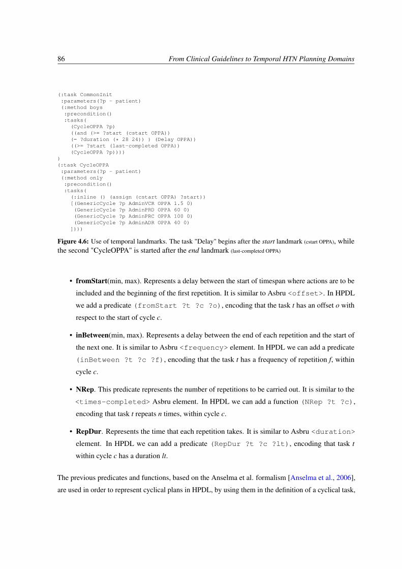
86 From Clinical Guidelines to Temporal HTN Planning Domains
(:task CommonInit:parameters(?p - patient)(:method boys:precondition():tasks(
(CycleOPPA ?p)((and (>= ?start (cstart OPPA))(= ?duration (* 28 24)) ) (Delay OPPA))((>= ?start (last-completed OPPA))(CycleOPPA ?p))))
)(:task CycleOPPA:parameters(?p - patient)(:method only:precondition():tasks(
(:inline () (assign (cstart OPPA) ?start))[(GenericCycle ?p AdminVCR OPPA 1.5 0)(GenericCycle ?p AdminPRD OPPA 60 0)(GenericCycle ?p AdminPRC OPPA 100 0)(GenericCycle ?p AdminADR OPPA 40 0)])))
Figure 4.6: Use of temporal landmarks. The task "Delay" begins after the start landmark (cstart OPPA), whilethe second "CycleOPPA" is started after the end landmark (last-completed OPPA)
• fromStart(min, max). Represents a delay between the start of timespan where actions are to be
included and the beginning of the first repetition. It is similar to Asbru <offset>. In HPDL
we add a predicate (fromStart ?t ?c ?o), encoding that the task t has an offset o with
respect to the start of cycle c.
• inBetween(min, max). Represents a delay between the end of each repetition and the start of
the next one. It is similar to Asbru <frequency> element. In HPDL we can add a predicate
(inBetween ?t ?c ?f), encoding that the task t has a frequency of repetition f, within
cycle c.
• NRep. This predicate represents the number of repetitions to be carried out. It is similar to the
<times-completed> Asbru element. In HPDL we can add a function (NRep ?t ?c),
encoding that task t repeats n times, within cycle c.
• RepDur. Represents the time that each repetition takes. It is similar to Asbru <duration>
element. In HPDL we can add a predicate (RepDur ?t ?c ?lt), encoding that task t
within cycle c has a duration lt.
The previous predicates and functions, based on the Anselma et al. formalism [Anselma et al., 2006],
are used in order to represent cyclical plans in HPDL, by using them in the definition of a cyclical task,

4.4 Mapping Asbru to the HTN formalism 87
that will be instantiated with initial state values for those predicates, as explained in the next section.
4.4 Mapping Asbru to the HTN formalism
This section shows that the Asbru time modeling constructs presented previously have a counterpart
HTN representation, supported by the formalism of [Anselma et al., 2006]. Although it is complex
to obtain intentional declarative knowledge from a more extensional XML model, we describe a
knowledge engineering method to extract a corresponding HTN domain from a CIG-based clinical
protocol, using a specific subset of the Asbru language, for the case study presented in chapter 5.
4.4.1 Objects and Types
The data model of both languages is very similar. While Asbru types are defined by means of the
element scale-def, HPDL types are arranged as a hierarchy where "object" is the upper node, and
described in a section called "(:types". Thus, a translation must be carried out, of every qualitative
scale-def as a corresponding HPDL type, so that each of its qualitative-entry is declared
as a constant in the domain.
4.4.2 Skeletal plans
For every Asbru "plan", starting in the root node and traversing the Asbru domain definition hierarchic-
ally, use the plan name for the definition of a corresponding HPDL compound task (in case it contains
plan activations) or a corresponding durative action (in case it is a leaf node, usually "user-performed")
in the planning domain. If the plan has any "argument" in its definition, translate it as a HPDL task
parameter (e.g. "?d - drug"). In addition, apply the next rules:
1. If the "plan-body" is composed of "subplans" of type "sequentially" and it is a sequence of
"plan-activations", translate them as a sequence of tasks calls, by enclosing them with ( ).
2. If it is composed of "subplans" of type "parallel", translate them as a parallel execution of tasks
calls, by enclosing them with [ ].
3. if it is composed of a "if-then-else" block, where an argument is evaluated and different plan-
activations are carried out for every argument value, this will be translated as several HPDL task

88 From Clinical Guidelines to Temporal HTN Planning Domains
methods, where every method precondition is the one defined on every "if" statement, and the
method body is a call to the corresponding HPDL task (the "plan-schema" activated).
4.4.3 Time annotations in plan activations
When a plan activation is time-annotated, using a reference to a plan-pointer as explained previously
in subsection 4.3.2, we can express the shifts regarding the pointed plan using a Delay task in HPDL.
By using such a task, we can define two temporal landmarks (we call them s and d, see Fig 4.7).
Init
OPPA OPPA
AdminPRD AdminPRC AdminVCR AdminADR
28 days
15 days
GenericCycle
Cycle OPPA
Abstraction processTask hierarchy
s d
Figure 4.7: Observe graphically the synchronization of two OPPA cycles, where each one last for 15 days and28 days pass since the start of the first one until the start of the second one. The temporal landmarks s and d canbe also observed.
The first one, s, is a temporal landmark that is defined within the task corresponding to the plan pointed
by plan-pointer (see Listing 4.1), and that will mark either the start (if ’state’ attribute is "activated") or
the end of the task (if ’state’ is "completed"). Then, we define the Delay task (Fig. 4.8) that contains
the definition of the second landmark, d, pointing to the end of this Delay task. The duration of the
delay has to be also specified when used (see Figure 4.6). Thus, besides defining these landmarks, we
use ?start, ?end and ?duration in order to annotate temporally the delayed tasks with respect to the
asserted landmarks. For example, in Figure 4.6, the second CycleOPPA is delayed 28 days after the
first one. This is carried out by defining the landmark that we have called s within CycleOPPA (i.e.
(assign (cstart OPPA) ?start)), declaring that the Delay task last 28 days and starts after
temporal landmark s, and finally that the second CycleOPPA must start after the temporal landmark d
(i.e. (last-completed OPPA), defined inside the Delay task itself, see Fig. 4.8).

4.4 Mapping Asbru to the HTN formalism 89
starting-shift <A> <B> <num>
AB num
start (A) >= end(B) + num
Delay task: (duration = num), where:
start(Delay) >= end(B)start(A) >= end(Delay)
ASBRU HPDL
;; definition of a Delay task in HPDL(:task Delay :parameters (?pname) (:method only :precondition () :tasks ( (:inline () (assign (last-completed ?pname) ?end)))
Figure 4.8: Expressing delays in Asbru and HPDL
4.4.4 Cyclical Plans
Finally, when a plan is defined with a "cyclical-plan-body", we considered that it is declared with at
least some arguments (see Listing 4.2): freq, nrep, fromstart, mindur, maxdur, partof. Furthermore,
we include drug and dose, since they are described in our case study, the Hodgkin Clinical Guideline
(later described in chapter 5).
Listing 4.2: An abstract cyclical plan for drug administration
<plan name="CicloAdministrar">
<arguments>
<argument name="drug" s-or-not="set" type="Drug"/>
<argument name="dose" s-or-not="set" type="amount"/>
<argument name="mindur" s-or-not="scalar" type="time"/>
<argument name="maxdur" s-or-not="scalar" type="time"/>
<argument name="fromstart" s-or-not="scalar" type="time"/>
<argument name="freq" s-or-not="scalar" type="time"/>
<argument name="nrep" s-or-not="scalar" type="amount"/>
<argument name="partof" s-or-not="set" type="CycleType"/>
</arguments>
<plan-body>
<cyclical-plan>
<cyclical-plan-body>
<plan-activation>
<plan-schema name="AccionAdministrar">
<argument-value name="drug">
<argument-ref name="drug"/>
</argument-value>
<argument-value name="dose">
<argument-ref name="dose"/>
</argument-value>
<argument-value name="mindur">
<argument-ref name="mindur"/>
</argument-value>
<argument-value name="maxdur">
<argument-ref name="maxdur"/>
</argument-value>
<argument-value name="partof">
<argument-ref name="partof"/>

90 From Clinical Guidelines to Temporal HTN Planning Domains
</argument-value>
</plan-schema>
</plan-activation>
</cyclical-plan-body>
<cyclical-time-annotation>
<time-range>
<duration>
<minimum>
<argument-ref name="mindur"/>
</minimum>
<maximum>
<argument-ref name="maxdur"/>
</maximum>
</duration>
</time-range>
<set-of-cyclical-time-points>
<time-point>
<now/>
</time-point>
<offset>
<argument-ref name="fromstart"/>
</offset>
<frequency>
<argument-ref name="freq"/>
</frequency>
</set-of-cyclical-time-points>
</cyclical-time-annotation>
<set-of-cyclical-complete-conditions>
<cyclical-complete-condition>
<times-completed number="nrep"/>
</cyclical-complete-condition>
</set-of-cyclical-complete-conditions>
</cyclical-plan>
</plan-body>
</plan>
Thus, in order to represent a cyclical task with HPDL, we use predicates instances (following the
temporal formalism of [Anselma et al., 2006]) in the problem file to define the cycle specification
(repetitions, offset, delay and duration) (see lines 1-5 of Listing 4.3). For example, from an activation
of a cyclical plan, as the one of Listing 4.2, where nrep=15, drug=prednisona and partof =OPPA, we
will extract the fluent (= (NRep Prednisona OPPA) 15), in order to express that drug is administered 15
times within the chemotherapy cycle named OPPA. We use those predicates in order to instantiate a
cyclical task that is defined in terms of methods prepare, loop and base (see List. 4.3):
• The prepare method identifies the start of the cycle by means of started_loop predicate (line
18), binds ?N variable to value 0 (line 14), and assign the temporal landmark (last-completed
?c) the instantiation time for this task (line 17).
• The do_loop checks as precondition that N ≤ NRep and that the loop has already started
(lines 23-24). If it is the first iteration (N=0), then the delay to be used is extracted from the

4.4 Mapping Asbru to the HTN formalism 91
fromStart value (line 28), and if N > 0 then the delay is extracted from the inBetween
value (line 30). Lines 32-37 are used to determine if it is a ’continuous’ administration or
not. Lines 39-40 recover temporal landmarks for the last iteration end time, and modify it
again by means of a Delay task which increases this temporal landmark (last-completed
?drug) by setting the corresponding delay duration using the delay_inbetween value acquired
previously, and calling the primitive action for the administration of this drug with a fixed start
time, equal to the updated last− completed value (line 41). Finally, the cyclical task is invoked
again (line 46) for iteration K = N + 1 (checking that the inBetween value is not 0).
• The base method just check the base case to stop the cycle (N ≥ NRep), negating the
started_loop predicate instance in that case (lines 49-52).
The Delay task is shown at the end of Listing 4.3 and the primitive action to administer a specific drug
is shown in Listing 4.4.
4.4.5 Generation of HPDL code
An overview of the algorithm to generate HPDL code, taking into account all the mapping rules
previously described, can be observed in Algorithm 6. Basically, the algorithm takes as input an Asbru
XML file, and generates a corresponding HPDL domain and problem files for the input Asbru domain.
In order to do that, it carries out four specific stages:
1. the initial generation of basic domain definitions (types, constants, predicates, functions).
2. It runs over the whole Asbru file, looking for skeletal plans that include a plan-pointer to
another skeletal plan (i.e. a time-annotated reference to a plan). This is needed in order to
detect anticipatedly which temporal landmarks must be declared when defining the tasks bodies
(through an "assign" operation carried out with an ":inline" method).
3. Afterwards, it parse every skeletal plan, generating the corresponding HPDL element, taking
into account several conditions that can occur. For example, if it is the root node of the Asbru
tree, we need to mark it so that its start time is defined by the value of the "startdate" instance
in the problem definition. If the skeletal plan parsed is referenced by a plan-pointer, then it
means that either at the beginning or at the end of its body, it must declare a temporal landmark

92 From Clinical Guidelines to Temporal HTN Planning Domains
Algorithm 6 Mapping Asbru models to HPDL DomainsInput: An Asbru domain model AOutput: HTN-PDDL Planning Domain D and Problem P
1. [Domain initial Definitions].1.1. [Types and Constants]. Parse the domain definitions in A. extracting the domain name Dn and a set Q of pairs
qi = {entry, type} from every "qualitative-scale-def" element. ∀qi ∈ Q, add once qi.type to section ” : types” in D,deriving from the generic type "object". ∀qi ∈ Q, add ”qi.entry− qi.type” to the section ” : constants” in D.
1.2. [Definition of predicates and functions]. Add to D the definitions of predicates and functions mentionedin subsection 4.3.3 (Fromstart, inBetween, Nrep, Repdur). Add also the ones used for the definition of temporallandmarks (cstart ?cq) and (last_completed ?cq), the predicate to identify the start date for the treatment of pa-tient p (startdate ?p ?ini) and the one to identify the beginning of an operation c in a cycle cq for patient p,(started_loop ?c ?cq ?p).2. [Preprocessing plan pointers]. Let S be the set of skeletal plans, S ⊂ A. As a preliminary operation, ∀ ki ∈ S, if kiis referenced by means of one or more "plan-pointers" in A, then add ki into a set K, storing the attributes "state" and"plan-name". Elements in K will be used later for defining temporal landmarks (see 3.2).3. [Parsing skeletal plans]. ∀si ∈ S generate a corresponding task or action Ti and:
3.1. [Initial Task]. If si is the root skeletal plan s1, a precondition based on the startdate predicate is added to thecorresponding HPDL task T1, annotating temporally the call to next task in the hierarchy, T2, to start on the start date i.e.((=?startdate ?ini)(T2)).
3.2. [Define Temporal Landmarks]. If si ∈ K, a definition of either a cstart (if si.state = ”activated”) or last-completed(if si.state = ”completed”) temporal landmark must be added to the corresponding HPDL task Ti, using an "assign"HPDL statement.
3.3. [Process Arguments]. If si has arguments, process them to be serialized into the :parameters of the correspondingtask.
3.4. [Parse Plan Body]. The plan body of each si is parsed into a structure Bi that identify it as one of 4 possiblepatterns: User-Performed, Subplan, If-Then-Else or Cyclical.4. [Serialize Tasks and Actions]. For each Bi:
4.1. [Durative Actions]. If Bi is user-performed, then a corresponding HPDL durative-action is generated. Include thedesired metatags for pretty print of the resulting plan.
4.2. [Compound Tasks]. If Bi is a subplan, then a corresponding HPDL task is generated. If it is of type parallel, it willinclude n plan activations. Each plan activation is similarly translated as a call to another HPDL task. These n calls areenclosed by brackets [ ... ]. If it is of type sequential, the calls are enclosed by parenthesis ( ... ).
4.2.1 [Time annotations for plan activations]. Each plan activation found, Pan, can have associated a time annotationtan. Let re f ∈ K be the plan pointer referenced in tan and ESS the value of the earliest-starting-shift value in tan. Let Tnbe the task called, corresponding to the plan activated in Pan.a) If tan.re f .state is activated then we prepend next expressions to call (Tn), as follows:
(start[Delay] >= (cstart tan.re f )), (duration[Delay] = tan.ESS), (Delay Tn), (start[Tn] >(last_completed Tn)), (Tn).b) If tan.re f .state is completed then we prepend next expressions to call (Tn), as follows:
(start[Delay] >= (last_completed tan.re f )), (duration[Delay] = tan.ESS), (Delay Tn), (start[Tn] >(last_completed Tn)), (Tn).
4.2.2 [Activations of Cyclical Plans]. If Pan activates a skeletal plan that is composed of a "cyclical-plan-body",extract the following predicate instances from the argument values in Pan, and put them into Problem P:(= Nrep (drug.value partof.value nrep.value)), (FromStart drug.value partof.value, offset.value), (Repdur drug.valuepartof.value mindur.value maxdur.value), (inBetween drug.value partof.value freq.value).
4.3. [If-Then-Else]. If Bi is an if-then-else block:4.3.1 [Variable Assignment]. If "then" and "else" branches are variable-assignments, translate each of them as HPDL
bind operations.4.3.2 [Different Task Methods]. If "then" and "else" branches are plan-activations, translate each as a different
task method, where the method precondition is the one for the if-then-else block, and the method body is a task call thatcorresponds to the skeletal plan activated.
4.4. [Cyclical Plans]. If Bi is a cyclical-plan, check that it is modeled with the necessary arguments, and identify theaction/task Bij that is activated within the cycle. Generate a cyclical HPDL task similar to the one at 4.3, but replacing thecall to the action/task with a call to Bij.

4.4 Mapping Asbru to the HTN formalism 93
definition recording the start or end time of the corresponding task. Finally, the skeletal plan
body can be of different type (a user-performed step, a subplan,a if-then-else block or a cycle).
4. Finally, the algorithm acts differently for each pattern identified in the plan-body: 1) If it is a
user-performed step, it generates a corresponding primitive action. 2) if it is a subplan then it
generates a corresponding compound task (parallel or sequential, where time-annotations are
also analyzed and translated for the plan-activations found. 3) If the body is an if-then-else
block, then it can be different conditional assignments of a variable, whose value is later used
as argument of a plan activation, or it can be directly different conditional plan activations. 4)
Finally, it can find a cyclical-plan-body, that must be translated as a generic cyclical task as the
one shown in Listing 4.3.

94 From Clinical Guidelines to Temporal HTN Planning Domains
Listing 4.3: outline of a recursive HPDL generic cyclical task using a delay task1 ;; In the problem file, using hours as time unit2 (fromStart PRD OPPA 0)3 (= (NRep PRD OPPA) 15)4 (RepDur PRD OPPA 1)5 (inBetween PRD OPPA 24)6 ...7 ;; In the domain file8 (:task CicloAdministrar9 :parameters (?p - patient ?drug -Drug ?partof - CycleType ?dose ?N)
10 (:method prepare11 :precondition (and (< ?N (NRep ?drug ?partof))12 (not (started_loop ?drug ?partof ?p))13 (fromStart ?drug ?partof ?start_delay)14 (bind ?N 0))15 :tasks (16 (:inline () (assign (cstart ?partof) ?start))17 (:inline () (assign (last_completed ?drug) ?start))18 (:inline () (started_loop ?drug ?partof ?p))19 (CicloAdministrar ?p ?drug ?partof ?dose ?N)20 )21 )22 (:method loop23 :precondition (and (started_loop ?drug ?partof ?p)24 (< ?N (NRep ?drug ?partof))25 (rep_dur ?drug ?partof ?min_dur ?max_dur)26 (fromStart ?drug ?partof ?start_delay))27 :tasks (28 (:inline (or (and (= ?N 0) (inBetween ?drug ?partof ?delay)29 (bind ?delay_inbetween ?start_delay))30 (and (> ?N 0) (inBetween ?drug ?partof ?delay)31 (bind ?delay_inbetween ?delay)) ) ())32 (:inline (or (and (inBetween ?drug ?partof 0)33 (bind ?mindurit (* (NRep ?drug ?partof) ?min_dur))34 (bind ?maxdurit (* (NRep ?drug ?partof) ?max_dur)))35 (and (not (inBetween ?drug ?partof 0))36 (bind ?mindurit ?min_dur)37 (bind ?maxdurit ?max_dur))) ())3839 (:inline (bind ?last_end (last_completed ?drug)) ())40 ((and (= ?start ?last_end) (= ?duration ?delay_inbetween)) (Delay ?drug))41 ((= ?start (last_completed ?drug))42 (AccionAdministrar ?p ?drug ?dose ?mindurit ?maxdurit ?partof))4344 (:inline (or (and (inBetween ?drug ?partof 0) (bind ?K (NRep ?drug ?partof)))45 (and (not (inBetween ?drug ?partof 0)) (bind ?K (+ ?N 1)))) () )46 (CicloAdministrar ?p ?drug ?partof ?dose ?K)47 )48 )49 (:method base50 :precondition (>= ?N (NRep ?drug ?partof))51 :tasks ( (:inline () (not (started_loop ?drug ?partof ?p))))52 ))5354 (:task Delay55 :parameters (?c)56 (:method only57 :precondition ()58 :tasks ( (:inline () (assign (last_completed ?c) ?end)))59 ))
Listing 4.4: outline of a durative action for carrying out a concrete drug administration1 (:durative-action AccionAdministrar2 :parameters (?p - patient ?drug - Drug ?dose ?mindur ?maxdur ?partof - CycleType)3 :meta (4 (:tag prettyprint " ?start; ?end; Dur: ?duration; Partof: ?partof ?c; ?p gets dose ?dose of drug ?drug")5 (:tag short "?drug ?dose")6 (:tag resource "?drug")7 (:tag monitoring "manual")8 (:tag Type "0")9 (:tag Summary "0")
10 )11 :duration (and (>= ?duration ?mindur)(<= ?duration ?maxdur))12 :condition ()13 :effect (assign (last_completed ?drug) ?end)14 ))

4.5 Related Work 95
4.5 Related Work
The research and development of Care Pathways is growing more and more, even though it is a
relatively recent concept. Concretely, 358 publications were found in Pubmed using the the term
"Clinical Pathway" in the [title] field (with 70% of them in the last 10 years), while 172 items were
found using the term "Care Pathway" (85% of them in the last 10 years). Different aspects and uses
have been observed when dealing with Care Pathways, but traditionally two main aspects can be
distinguished in the literature: their development and their later operation in a real scenario (see
[de Luc, 2000]).
While the work presented is clearly directed to the development aspect, it also cares about the later
operation of the generated pathway. Of course, this worry firstly arises from an IT perspective, since
developing methods and tools, that can be useful for the clinicians in this scenario, is our main aim.
Nonetheless, we also care about the correct operation of the care pathway from the point of view of
patient safety. Without any doubt, this was the main reason to give relevance to the fact that the source
of knowledge for building up a personalized Care Pathway should be a predefined Clinical Guideline,
a tool that has already demonstrated its added value in the clinical community [Woolf et al., 1999].
Note also that there is a growing concern that the enormous effort that goes into creating the guidelines
may not be matched by the level of adherence to them in practice, and so the use of CIG languages
and Care Pathways is seen as a potential remedy to improve compliance [Patkar & Fox, 2008]. A step
forward, in order to achieve this adherence and compliance, is offered by the presented methodology.
In [Tu & Musen, 2000] some different computational paradigms and mechanisms of modeling and
managing clinical guidelines are explored, evaluating them in terms of their support for multiple
patient-care tasks (making of decisions, sequencing of actions, setting of goals, interpretation of data,
and refinement of actions). Some of the advantages and limitations of each approach are summarized,
concerning the mentioned tasks. For example, the mostly used Petri Nets formalism "is very good
for modeling complex concurrent processes and can integrate guideline-specified activities with
organizational models to manage workflow, but it does not have the rich argumentation structure for
decision making that other formalisms provide". The approach presented in this chapter based in HTN
AI planning, somehow brings all these requirements together.
Some recent works have paved the way for using AI planning techniques for existing challenges that re-
mains in the area of computerized Clinical Guidelines [Anselma & Montani, 2008]. In [Bradbrook et al.,
2005], the authors described an overview of the set of steps to produce and use a computerized guideline,

96 From Clinical Guidelines to Temporal HTN Planning Domains
and how AI planning techniques could be relevant to address these challenges, focusing in POP, HTN
and CBR techniques, and already issuing the need to accommodate clinician and patient preferences,
besides maintaining patient safety. In any case, that work is mostly a position paper that already
intuited the similarities and common aims of both CPG (it is concretely focused on the PROforma
formalism) and AI planning communities. A relevant work for reviewing the needs, in the scope of
knowledge representation and engineering, that arise when dealing with the scheduling of clinical
tasks, and the differences with execution needs, was presented in [Weng et al., 2002].
Most of the literature related to the aims presented in this chapter, is directed to deal only with the exe-
cution of Clinical Guidelines [Anselma & Montani, 2008; Isern & Moreno, 2008; Seyfang & Miksch,
2004; Votruba et al., 2006] but, up to date, few approaches provide decision support capabilities to the
clinicians, at the level of complexity presented on this chapter, automatically generating resource-based
and patient-tailored Care Pathways that can be used in a reminder-based manner, starting from the
expert knowledge in a predefined clinical protocol, and dealing also with the interpretation of complex
temporal knowledge.
For example, ONCOCIN [Kahn et al., 1985], one of the first CDSS that attempted to model spe-
cification of decisions and sequencing of actions over time, pioneered a network-based approach to
modeling cancer clinical-trial protocols. However, one of its limitations was that "events that are
not known to the reasoning system will not be represented in the temporal network, so static time
intervals have to be specified in advance". Note that this issue is overcome by our approach, by using
and interpreting temporal landmarks, where deliberative reasoning and dynamic temporal constraint
validation is interleaved, to dynamically find a solution to the problem.
More recently, the well-known work by [Quaglini et al., 2000] share similar objectives as the presented
approach, translating Clinical Guidelines, modeled with a graphical tool called GUIDE, into the formal
representation of Petri Nets. However, a further analysis of temporal knowledge and its translation, as
presented in this chapter, was not considered. The TADS system [Patkar & Fox, 2008] pursue similar
objectives, where a guideline is modeled with the PROForma formal language, and later used for
decision support. While tackling a similar problem, it presents some limitations concerning its strict
workflow-based design, which impose rigidity, for example compelling the doctors to take decisions
always in the same order. Furthermore, not much is said about its capability to consider the allocation
of institutional resources, since it is definitely more directed to offer recommendations in each step of
the care plan, unlike our aim of generating end-to-end Care Pathways that unfold over time.
As a matter of fact, a common shortcoming of the multiple approaches that have arisen in the community

4.5 Related Work 97
of electronic Care Pathways is the lack of flexibility. This lack may come out from the rigidity of
design tools used for the pathway formalization (like workflow tools [Patkar & Fox, 2008] or Petri
Nets [Fox et al., 2008]), and it is clearly one of the handicaps that must be overcome in this area. This
can also happen due to the static verification of the constraints introduced in the model, a problem our
approach lacks of, since the constraints verification and analysis is carried out dynamically, supported
by a subjacent temporal network, which is build up and modified in every step of the reasoning process,
offering a more flexible mechanism. Of course, the need of flexibility in the application of a particular
Care Pathway, depends on the grade of adherence to the clinical protocol that is needed or, said another
way, is highly associated to the variance (the real deviation from the plan initially generated) that can
exist from the Care Pathway developed. Nonetheless, this also seems to occur in the application of
old-fashioned paper-based Care Pathways [Allen et al., 2009].
Thereby, work in progress is being carried out in order to achieve a higher degree of flexibility
[Fdez-Olivares et al., 2011b; Sánchez-Garzón & Fdez-Olivares, 2011], so that our approach can be
used in more complex scenarios. This is being done considering exception handling, including a
monitoring engine that detects inconsistent situations and that triggers either a plan repair or replanning
step, in order to adapt to the new situation. This will aid to outreach a broader array of possible
cases of application where the expected clinical variance is much higher. In fact, the application of
HTN Planning and Scheduling have already confronted similar issues in the past [Ayan et al., 2007;
Drabble et al., 1997; Warfield et al., 2007], as it also happens in the emergent research area of Adaptive
Case Management [Leoni, 2009]. Moreover, one of the recent challenges for the development of CDSS
is how to formalize decisions in a context-sensitive way within extended care plans and workflows
[Fox et al., 2010], an issue where the application of AI planning techniques can definitely provide
some advancement.
Finally, it is important to highlight that the appropriateness of using electronic Care Pathways for
decision support, like it happens with paper-based systems, might depend on the concrete disease (this
feeling is also shared by the oncologists that participate in the project). In any case, our approach has
shown to be useful for the case study presented in chapter 5, the Hodgkin disease guideline, since the
recommendations offered by the guideline were very accurate, and it is a low-frequency domain where
the application of the techniques presented are actually very interesting. Results about this case study
are presented in chapter 5.

98 From Clinical Guidelines to Temporal HTN Planning Domains

Chapter 5Results
This chapter is directed to present the results obtained from carrying out different experiments, in order
to check the usefulness and soundness of the methods proposed in the thesis. Section 5.1 describes the
experiments carried out for the translation of Business Process Models, while section 5.2 describes
the one related to the translation of clinical protocols modelled by means of Computer Interpretable
Guidelines languages.
5.1 Mapping BPM models to HTN domains
In order to show the soundness of the methods explained in chapter 3 for the automatic generation of
HTN planning domain models from Business Process Models, a tool called JABBAH was developed,
with the aim to be presented at the third ICKEPS Competition (2009). Finally, it was one of the winners
of this competition (the itSIMPLE tool was the other winner). In order to check its operation, some
real experiments were carried out, and they also described later. The following subsection describes
the JABBAH framework.
5.1.1 The JABBAH framework
Starting from the methodology defined for translating BPM models into HTN planning domains,
described in chapter 3, an extensible framework called JABBAH has been developed, able to carry out
this translation. JABBAH stands for "Java Application framework for the translation Between BPM

100 Results
And HPDL". It has been developed in Java, and it is based on jgrapht library1, very useful for creating
graph data structures, with fully customized nodes and edges implementation. Details about source
code, or even a screencast about how JABBAH operates can be found in its website2.
(a) (b)
(c) (d)
(e) (f)
Figure 5.1: Some screenshots of JABBAH in action
1http://jgrapht.sourceforge.net/
2JABBAH homepage, http://sites.google.com/site/bpm2hth/home

5.1 Mapping BPM models to HTN domains 101
The JABBAH system provides a neat tool for analysts that need to perform resource allocation analysis
and anticipated process planning on business workflows, embedding a non-trivial transformation of
BPMN-expressed process models in terms of Hierarchical Task Networks. Figure 5.1 shows some
screenshot of JABBAH in action. Starting from a process model modeled with the BPMN notation (for
example, of a patient admission into an hospital) (a), that has been designed as a well-structured process
model (see these properties commented in chapter 3) (b), and introducing some extended attributes for
every activity, related to scheduling and allocation (c), we show how JABBAH, given an XPDL file as
input (d), can obtain a corresponding graph model (e), transforming it into a semantically equivalent
tree model (e). After this transformation, the corresponding planning domain and problem files can
be generated (by identifying the workflow patterns in the tree model) (f). The later interpretation of
domain and problem files by an HTN planner, produces a process instance (or plan) that takes into
account all the constraints expressed in the original model.
Next section describes the experiments that were designed in order to check that JABBAH operates
correctly, and that the HTN planning strategy is ideal for accomplishing the aims that we pursue of
obtaining a process plan that respects the constraints introduced, either implicitly or explicitly, in the
input process model.
5.1.2 Experiments
Some experiments based on real scenarios have been carried out by using JABBAH, with a twofold
aim in mind. One the one hand, to show that the well-structured process models chosen have
a corresponding HTN representation able to capture the knowledge present in the process (even
considering embedded subprocesses) and on the other hand, to show that it can be used to carry out a
planning process in order to obtain a context-dependent plan that considers the task ordering and the
organization resources, under different environment conditions.
Specifically, the experiments have been designed in order to show the planning and scheduling
capabilities that our approach introduces into the BPM life cycle (see Figure 2.11 in chapter 2) and,
furthermore, to show that this planning stage is carried out efficiently and correctly, guided by the
knowledge present in a changing environment, and respecting all the constraints that were introduced
in the original process model.
Concretely, some expected outcomes of these experiments are: 1) to check that a corresponding HTN
representation exists for process models that include a combination of (possibly nested) workflow

102 Results
patterns, 2) to find a plan instance that keeps the temporal semantic associated to those workflow
patterns, 3) to check that the interpretation of the same HTN domain can find different plan instances
for different combinations of input parameters (e.g. decision gateways values), 4) to show that both
planning (finding the activities that form part of the plan) and scheduling (determining a task ordering
that respect time constraints, assigning also resources to activities) are carried out in order to find a
situated plan.
Concerning the selected scenarios, we have used JABBAH over two real processes, in the field of
e-learning and e-health3, described next.
E-learning Center Management The first process model, represents how to develop and deploy a
specific e-learning course within the e-learning center of the University of Granada (CEVUG4). In
the operation of this center (where the author of this thesis worked for seven years), an incoming
course development request is typically made by customers (e.g. teachers that belong to the University
or external companies that want to develop learning material). In order to have the course ready for
deployment within a specific online Learning Management System, a number of steps have to be
carried out in this process, and it implies the participation and the correct interaction of different
roles (instructional designers, graphic designers, HTML developers, sysadmins, tutors, students, etc).
These roles are encoded by using different Lanes in the BPMN process model. An outline of the
corresponding process model modeled with this notation can be observed in Figure 3.2. Note that
some of the tasks needed to complete the process can only be carried out by a specific worker/role
(i.e. participants are associated to specific lanes when they are defined, and the activities are located
inside its corresponding lane). Furthermore, these activities can have some ordering dependencies.
For example, the task content authoring’ (A2) could only be completed by a content author and the
task of ’training authors on instructional design’ (A1) had to be previously completed by the training
department. So, the election of a specific worker for a specific task will be conditioned by his ability to
complete it, and possibly by his temporal availability.
Thus, having some available workers at the center, with different capabilities each, the manager is
interested in knowing how long the course development will take, and which workers will be involved
in the process. By using JABBAH, a plan instance can be finally obtained providing the managers
3both are available in the "domain repository" section of the JABBAH website
4http://cevug.ugr.es

5.1 Mapping BPM models to HTN domains 103
information about the workers allocation and the make-span of the whole course development, helping
to do decision-making upon the course request.
Hospital Patient Admission The second process model (Figures 5.2 and 5.3) represents a general
care-process in an hospital, representing the steps to be carried out since the moment that a particular
patient comes into the hospital, until the moment when the health insurance billing action for this
patient takes place. Similarly to the previous experiment, different personnel is needed for every
activity, but a more complex set of nested workflow patterns is represented. Moreover, the design of
this experiment is concretely directed to show that different plan instances are obtained depending of
the conditions of the patient, and also to show that subprocesses embedded into the process model can
be managed by JABBAH. Furthermore, by using JABBAH to obtain the multiple plan instances of the
process, could be useful in order to evaluate that the processes stablished to manage income patients
have been designed correctly, by carrying out a "whatifying" process, detecting possible bottlenecks in
the model or lack of personnel in the health process.
Next section gives details on how the experiments were carried out, and describes the results obtained.
5.1.3 Findings
Table 5.1 describes the different elements of the BPMN notation that were found in the two models,
and the corresponding HTN elements that were generated by JABBAH. It may be used to clarify how
the hierarchical structure of HTNs is being used and why it is helpful in order to achieve the aim that
we pursue.
Process Lan
es
Act
iviti
es
Subp
roce
sses
star
ting
XO
R
clos
ing
XO
R
star
ting
AN
D
clos
ing
AN
D
Seri
alB
lock
Alte
rn.B
lock
Para
llelB
lock
Dur
.Act
ions
Init
Con
d.
Obj
ects
Para
met
ers
e-learning 8 13 0 1 1 2 2 2 1 2 13 7 6 1e-health 10 16 1 4 4 1 1 5 4 1 16 15 10 4
Table 5.1: BPMN elements and the corresponding HTN elements generated for both models
Although the plans obtained are merely a sequence of actions, it is important to realize that they are
obtained from a domain that has been automatically generated, that include the procedural knowledge
already existing in the initial process model. For example, the e-learning domain contains 13 activities
(it has no subprocesses), and 2 serial, 1 alternative and 2 parallel blocks were obtained. These

104 Results
Figure 5.2: Outline of the patient admission scenario process model (part 1)

5.1 Mapping BPM models to HTN domains 105
Figure 5.3: Outline of the patient admission scenario process model (part 2)

106 Results
Figure 5.4: Output plan as a Gantt diagram (letters next to boxes are the resources assigned to each activity)
blocks include procedural knowledge (e.g., for parallel blocks, a set of actions S1 must be executed
concurrently with respect to another set of actions S2) that is really complex to describe by using
non-HTN planning. However, by using the HTN paradigm, a natural and direct parallelism exists
between serial or parallel blocks and the multiple task ordering methods that HTN languages like
HPDL are able to manage. At the same time, an alternative block of n tasks can be represented with n
alternative HTN methods. Note that this implicitly represents a knowledge-based search heuristic, that
is, knowledge-based rules that are used to guide the search of a solution plan, something that cannot be
done straightforward with classical PDDL-based planners. Some concrete results are commented next.
In the first process, using a specific workers assignment for the multiple activities carried out in the
e-learning center, as well as estimated duration of every activity, we have checked the viability of the
output plans, and also that task ordering is respected, i.e. the following assignment of personnel (that
it actually realistic in the context of CEVUG): Emilio (training), Storre (authoring), Miguel (html),
Jose (graphic), Arturo (admin) and FMoreno (quality), result on the plan shown as a Gantt diagram at
figure 5.4.
Concerning the e-health process, given its higher variability, we checked how our tool was able to
generate different process plan instances using the control knowledge extracted from the process model
and respecting some different nested workflow patterns found on it. It is also shown the recursion
capabilities of our proposal, by interpreting and translating correctly the embedded subprocesses
included. Since this process provides several decision gateways, we better observe how process
planning is carried out, given different input parameters which can vary in real situations (e.g. is it an
emergency? does the patient need an urgent operation?).

5.1 Mapping BPM models to HTN domains 107
Each row in table 5.2 show the different instances found for the decision points (values 0/1 in the first
set of columns represent false/true values for the input parameters), showing the concrete allocation
of workers (participants p1 to p10) to every activity, in the case that it is carried out (the second set
of columns in the table). Moreover, decisions taken by the planner in the search process (planner
expansions), the number of generated nodes, and the total make-span of every plan instance are
displayed. It is important to highlight that each plan instance was obtained in less that 1 second.
Therefore, our experiments make clear that a search process is necessary among the possibly different
alternative course of actions expressed in a process model, also taking advantage of the knowledge
expressed on it (note that the process model itself already discard some alternatives by using control
structures). Thus, we opted for using HTN planning, that precisely describes methods to obtain valid
plans, incorporating procedural knowledge to avoid exploring nonsense or wrong alternatives. It
is important to highlight that non-hierarchical planning is not expressive enough to represent these
control structures, and that it is based on an exhaustive search process not guided by knowledge, so
its use would be costly, searching over alternatives that are not considered initially in the process
model. What’s more, we have shown that it is not necessary for a process model to include hierarchical
structures (i.e. it is a representation based on a graph model) in order to obtain an HTN representation.
Nonetheless, the HTN domains that JABBAH automatically generates, are able to represent the
control structures that are usually present in business process models by means of explicit hierarchical
structures, something that cannot be done directly with a classical planner.
Therefore, we have checked the proposed goals with non-trivial scenarios. Nonetheless, future work
will be done in order to cover a bigger subset of process models (i.e. cooperative process models,
where not only normal flows but also message flows and associations between can be represented), and
also to represent complex temporal constraints that could be expressed on them (see chapter 6).
In any case, similar structures (i.e. synchronizations between activities or temporal constraints) are
managed also by HTN structures, a we will observe in the next section, that describes the results found
by our second contribution in the field of healthcare processes.

108 Results
emergencyspecialurgentintensive
RegisterPatient
OpenEmergency
GeneralExam
GeneralCare
SpecialExam
PerformObservation
IntensiveCare
PrepareAnesthetic
FillOTSheet
PatientReception
PerformSurgery
VitalSignMonitor
SurgeryReport
CheckoutPatient
BillServices
ProcessBill
Actions
Expansions
Gen. nodes
Make-span
00
00
p3p5
p7p3
p2p1
65
1135
00
01
p3p5
p7p3
p2p1
65
1135
00
10
p3p10
p10p10
p9p10
p10p3
p2p1
106
1658
00
11
p3p10
p10p10
p9p10
p10p3
p2p1
106
1658
01
00
p3p5
p6p7
p3p2
p17
714
410
10
1p3
p5p6
p8p3
p2p1
77
1436
01
10
p3p10
p10p10
p9p10
p10p3
p2p1
106
1658
01
11
p3p10
p10p10
p9p10
p10p3
p2p1
106
1658
10
00
p4p5
p7p3
p2p1
65
1129
10
01
p4p5
p7p3
p2p1
65
1129
10
10
p4p10
p10p10
p9p10
p10p3
p2p1
106
1652
10
11
p4p10
p10p10
p9p10
p10p3
p2p1
106
1652
11
00
p4p5
p6p7
p3p2
p16
511
351
10
1p4
p5p6
p8p3
p2p1
77
1430
11
10
p4p10
p10p10
p9p10
p10p3
p2p1
106
1652
11
11
p4p10
p10p10
p9p10
p10p3
p2p1
106
1652
Table5.2:
Differentplan
instancesand
allocationfore-health
processaccording
todifferentinputvalues

5.2 Automated generation of patient-tailored care pathways 109
5.2 Automated generation of patient-tailored care pathways
This section is devoted to explore the results that we found by applying the methodology described
in chapter 4, in the context of a regional project called Oncotheraper where, impulsed by the needs
expressed by the doctors of several hospitals of the Andalusian Public Health System, a CDSS was
developed [Fdez-Olivares et al., 2011a] for the automated generation of patient treatment plans for
specific diseases in the area of oncology pediatrics. This CDSS is based on the initial modeling of
clinical protocols with the HPDL language. However, this modeling is far from being straightforward,
and new Knowledge Engineering techniques were developed (chapter 4) in order to simplify the
modeling stage, bringing the HTN AI P&S technology closer to the healthcare domain.
5.2.1 Context: the Hodgkin’s disease guideline
One of the main weaknesses in the services provided in pediatric oncology in the hospitals of the
Andalusian Public Health System, is that the clinical tasks and decision-making processes in the
planning of oncology treatments are done manually, without the help of specific IT tools. This fact
negatively affects current trends in the healthcare sector, which attempt to offer efficient, quality care
with total safety guaranteed for the patient. This planning stage is manually done by the oncologist, in
a text document used as a guide for treatment in practice and patient monitoring. Furthermore, doctors
are presented with major problems in achieving these aims: multiple variables in drugs and possible
treatments, multiple patient profiles which may influence treatment, time-consuming treatment design,
and the need to take complex medical protocols into account. Thus, the tasks and clinical decisions
of this crucial stage are prepared without IT support, making it much more difficult to achieve the
healthcare goals of quality healthcare, patient safety and efficient provision of service.
The Hodgkin’s disease guideline We have centered our study concretely in the Hodgkin disease
clinical protocol, developed by the Spanish Society of Pediatric Oncology (SSPO). This disease
presents the problems commented above, and fits perfectly with the aim of our approach, since the
doctors must absolutely comply with the clinical protocol, trying to minimize the deviations from
it, in order to achieve a successful treatment. The goal of an oncologist when planning a treatment
for this disease, is mainly to schedule chemotherapy, radiotherapy and monitoring of a patient. A
schema of the treatment workflow process indicated in such protocol, as well as the temporal patterns
to administrate every chemotherapy cycle (OPPA, OEPA and COPP) are outlined in Figure 5.5.

110 Results
Figure 5.5: Workflow Schema of the Hodgkin’s Disease Clinical Protocol
First a child must receive two chemotherapy cycles (of type OPPA or OEPA, depending on the genre)
and then two cycles more, of type COPP. If a complete remission of the tumour is not achieved
by patients of Group1 then radiotherapy sessions start. If the stratification group (decided by the
oncologist) is either Group2 or Group3, two more COPP cycles must be administrated. In case of a
patient of Group3, additional radiotherapy sessions must be administrated when a complete remission
of the tumour is not detected.
Note that the protocols like the one described above, are usually detailed by doctors in text documents
(Clinical Practice Guidelines or CPGs), so that they can use these documents as a support for the act of
carrying out decisions in every point of decision through the process. Indeed, these protocols are also
process models (similar to the ones shown in the previous section of this chapter), but they differ in the
complexity of the data and the temporal constraints that they usually need to express.
In [Fdez-Olivares et al., 2011a], it was described how to deal with the formalization of this protocol
with the HTN formalism, in order to achieve the aim of building up a CDSS for the proposed aim of
aiding doctors to generate plans. However, it was made clear that the formalization of clinical protocols
directly with planning languages like HPDL are extremely difficult, specifically because modeling
temporal constraints (e.g. synchronizations between tasks or cycles) is far from being straightforward
to carry out. In fact, knowledge representation formalisms known as Computer Interpretable Guidelines
(CIG) have arisen, that precisely aim to facilitate the computational representation of these protocols.
Thereby, in chapter 4, a methodology is described that aims to move from a formal CIG representation
of a clinical guideline into an HTN planning domain.

5.2 Automated generation of patient-tailored care pathways 111
Clinical Guidelines
and Protocols
Computer Interpretable Guidelines
Start
Hierarchical Task Network Model Patient Profile
Compound Tasks
Cyclical Tasks
Primitive Tasks
Resource Constraints
Planning Goal
Cycles Temporal Specification
Planning Domain Planning Problem
Planning Specification
Clinicians
Knowledge Engineers
Planning & Scheduling Module
Plan Repair Module
Replanning Module
Patient Tailored
Care Pathway
Web-based Plan
Visualization (e.g. Gantt)
Mapping to standard Process
Definition
Plan GenerationPlan Delivering
User
Inte
rfac
e
Plan Enactment
1
2
34
5
Temporal ReasoningModule
CIG Connector EHR EHR
ConnectorHIS
ConnectorHIS
HTN Planner
BPM Runtime Engine
Monitoring and Exception Handling Unit
6 Plan Repair and Replanning
Figure 5.6: Architecture for expressing clinical protocols in terms of HTNs in order to develop a AI-basedCDSS
5.2.2 Experiments
In order to show the contribution of the methodology described, we carried out the life-cycle shown in
Figure 5.6, that is actually a detailed view of Figure 4.1, for the protocol of the Hodgkin disease (step 6
was not carried out, since the plan repair component is work in progress). The aim of this experiment
is to show that:
1. The CIG languages, concretely Asbru, are actually very similar to HPDL, and a transformation

112 Results
can be carried out between both models.
2. The HPDL language is able to correctly represent most of the temporal patterns that are
commonly found in clinical protocols, and that Asbru is able to represent.
3. The IACTIVE planner is able to improve the generation of plans for long-term care of patients,
that needs to dynamically manage temporal constraints that are not known at the beginning
and that are not explicitly defined in the protocol as absolute constraints (i.e. they are dynamic
constraints that are relative to other activities or temporal intervals).
4. Although Asbru is not able to describe neither the patient profile nor the hospital resources, the
HPDL model automatically generated from the Asbru model can be augmented with these data,
which makes it very powerful by putting the control flow information provided by the original
guideline in the context of a real use case, providing support for decision making adapted to
realistic constraints.
These experiments were carried out during a 3-month research stay in Amsterdam (The Netherlands),
under the supervision of Annette ten Teije, lecturer of the Knowledge Representation and Reasoning
group (KR&R) of the Vrije University. A full paper was accepted in the European Conference of
Artificial Intelligence in Medicine [González-Ferrer et al., 2011b] (only 18 of 113 papers submitted
were accepted as full papers). Furthermore, it was also selected (as one of only six) for possible
publication of a extended version in a future special issue of the Journal of Artificial Intelligence in
Medicine (Elsevier).
Note that the results described are directly related to the development of the CIG connector (see Figure
5.6), and that some of the other steps, like the EHR/HIS connector, or the exception handling unit, are
still work in progress being carried out by other members of our research group. Either way, Figure
5.6 is shown to contextualize the final aim and contributions of the results described. So, looking at the
figure, five steps are needed, explored in the following paragraphs.
Knowledge Acquisition and Formulation of the Guideline First, the clinical guideline is described
by experts in natural language (70 text pages) starting from oncologist’s experience (the guideline of
the Hodgkin’s disease was provided by the SSPO). Then, it is modeled with DELT/A (the Document
Exploration and Linking Tool, see Figure 5.7) [Votruba et al., 2004], obtaining a computer interpretable
XML-based Asbru model of the guideline. Basically, the set of actions to be carried out is described as

5.2 Automated generation of patient-tailored care pathways 113
different skeletal plans that are arranged hierarchically. Furthermore, the different fragments of model
being defined can be associated with the original text guideline through hyperlinks.
Figure 5.7: Modeling the Hodgkin disease protocol in Asbru by using the DELT/A tool. On the left side, youcan see the original protocol document, and on the right side you can model in Asbru and link at the same timeparts of the XML model with the document on the left
Generation of the Temporal HTN Model: Asbru2HPDL Once that the Asbru model is finished,
a translation to HPDL is necessary. To that end, we developed a Java tool named Asbru2HPDL5 that
carries out 2 basic steps: (a) the acquisition of the knowledge present on the Asbru CPG by parsing
it into a memory structure (a set of java classes), supported by the NanoXML library, a light XML
parser that simplifies this task, and (b) the serialization of this memory structure into HPDL domain
and problem (Algorithm 6 in chapter 4 is devoted to describe this step).
Thus, we obtain (see stage 2 of Figure 5.6) a planning domain (see it partially at Listing 5.1) that
includes a high-level task goal, subsequently decomposed by the planner following the strategy
(compound tasks and primitive actions) and the temporal constraints declared in the HTN domain,
previously translated from the original formal representation of the guideline in Asbru. Furthermore,
we automatically add to the problem file the predicate instances that explicitly define the temporal
5available at http://gitorious.org/asbru2hpdl

114 Results
specification of cyclical tasks (see Listing 5.2).
Listing 5.1: Part of the HPDL domain automatically generated by Asbru2HPDL starting from the Hodgkin’s
disease guideline modeled in Asbru
1
2 ...
3 (:predicates
4 (fromStart ?x ?cic ?y)
5 (rep_dur ?x ?cic ?min ?max)
6 (inBetweenAll ?x ?cic ?y)
7 (startdate ?x ?y)
8 (started_loop ?c ?cq ?p)
9 )
10 (:functions
11 (NRep ?x ?cic)
12 (cstart ?cq)
13 (last_completed ?x)
14 )
15
16 (:task Init
17 :parameters (?p - patient ?sex - gender)
18 (:method only
19 :precondition(startdate ?p ?ini)
20 :tasks (
21 (:inline (or (and(= ?sex H)(bind ?tipociclo OEPA))
22 (and(not(= ?sex H))(bind ?tipociclo OPPA))) ())
23 ((= ?start ?ini)(Quimioterapia ?p ?tipociclo))
24 )
25 )
26 )
27
28 (:task Quimioterapia
29 :parameters (?p - patient ?argtipo - CycleType)
30 (:method methodA
31 :precondition(= ?argtipo OEPA)
32 :tasks((TWO-OEPA-TWO-COPP ?p))
33 )
34 (:method methodB
35 :precondition(not (= ?argtipo OEPA))
36 :tasks((TWO-OPPA-TWO-COPP ?p))
37 )
38 )
39
40 (:task TWO-OEPA-TWO-COPP
41 :parameters (?p - patient)
42 (:method only
43 :precondition()
44 :tasks (
45 ((OEPA ?p)((and (>= ?start (cstart OEPA))(= ?duration 672))(Delay OEPA))
46 ((>= ?start (last_completed OEPA))(OEPA ?p))((and (>= ?start (cstart OEPA))(= ?duration 672))(Delay COPP))
47 ((>= ?start (last_completed COPP))(COPP ?p))((and (>= ?start (cstart COPP))(= ?duration 672))(Delay COPP))
48 ((>= ?start (last_completed COPP))(COPP ?p)))
49 )
50 )
51 )
52
53 (:task TWO-OPPA-TWO-COPP
54 :parameters (?p - patient)
55 (:method only

5.2 Automated generation of patient-tailored care pathways 115
56 :precondition()
57 :tasks (
58 ((OPPA ?p)((and (>= ?start (cstart OPPA))(= ?duration 672))(Delay OPPA))
59 ((>= ?start (last_completed OPPA))(OPPA ?p))((and (>= ?start (cstart OPPA))(= ?duration 672))(Delay COPP))
60 ((>= ?start (last_completed COPP))(COPP ?p))((and (>= ?start (cstart COPP))(= ?duration 672))(Delay COPP))
61 ((>= ?start (last_completed COPP))(COPP ?p)))
62 )
63 )
64 )
65
66 (:task OPPA
67 :parameters (?p - patient)
68 (:method only
69 :precondition()
70 :tasks (
71 (:inline () (assign (cstart OPPA) ?start))
72 [(CicloAdministrar ?p PRD OPPA 60 0)
73 (CicloAdministrar ?p VCR OPPA 1.5 0)
74 (CicloAdministrar ?p PRC OPPA 100 0)
75 (CicloAdministrar ?p ADR OPPA 40 0)
76 ]))
77 )
78
79 (:task OEPA
80 :parameters (?p - patient)
81 (:method only
82 :precondition()
83 :tasks (
84 (:inline () (assign (cstart OEPA) ?start))
85 [(CicloAdministrar ?p PRD OEPA 60 0)
86 (CicloAdministrar ?p VP16 OEPA 125 0)
87 (CicloAdministrar ?p VCR OEPA 1.5 0)
88 (CicloAdministrar ?p ADR OEPA 40 0)
89 ]))
90 )
91
92 (:task COPP
93 :parameters (?p - patient)
94 (:method only
95 :precondition()
96 :tasks (
97 (:inline () (assign (cstart COPP) ?start))
98 [(CicloAdministrar ?p VCR COPP 1.5 0)
99 (CicloAdministrar ?p PRD COPP 40 0)
100 (CicloAdministrar ?p PRC COPP 100 0)
101 (CicloAdministrar ?p CFM COPP 500 0)
102 ]))
103 )
104
105 (:task CicloAdministrar
106 ...
Listing 5.2: Part of the HPDL problem automatically generated by Asbru2HPDL containing the temporal
specifications of cycles extracted from the Asbru guideline
1
2 ;;administration of PRD in cycle OPPA
3 (= (NRep PRD OPPA) 15)
4 (fromStart PRD OPPA 0)
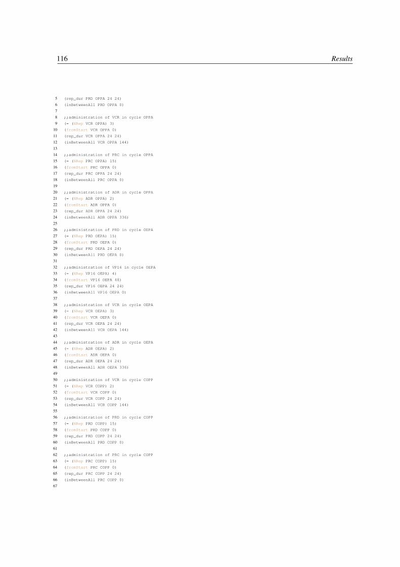
116 Results
5 (rep_dur PRD OPPA 24 24)
6 (inBetweenAll PRD OPPA 0)
7
8 ;;administration of VCR in cycle OPPA
9 (= (NRep VCR OPPA) 3)
10 (fromStart VCR OPPA 0)
11 (rep_dur VCR OPPA 24 24)
12 (inBetweenAll VCR OPPA 144)
13
14 ;;administration of PRC in cycle OPPA
15 (= (NRep PRC OPPA) 15)
16 (fromStart PRC OPPA 0)
17 (rep_dur PRC OPPA 24 24)
18 (inBetweenAll PRC OPPA 0)
19
20 ;;administration of ADR in cycle OPPA
21 (= (NRep ADR OPPA) 2)
22 (fromStart ADR OPPA 0)
23 (rep_dur ADR OPPA 24 24)
24 (inBetweenAll ADR OPPA 336)
25
26 ;;administration of PRD in cycle OEPA
27 (= (NRep PRD OEPA) 15)
28 (fromStart PRD OEPA 0)
29 (rep_dur PRD OEPA 24 24)
30 (inBetweenAll PRD OEPA 0)
31
32 ;;administration of VP16 in cycle OEPA
33 (= (NRep VP16 OEPA) 4)
34 (fromStart VP16 OEPA 48)
35 (rep_dur VP16 OEPA 24 24)
36 (inBetweenAll VP16 OEPA 0)
37
38 ;;administration of VCR in cycle OEPA
39 (= (NRep VCR OEPA) 3)
40 (fromStart VCR OEPA 0)
41 (rep_dur VCR OEPA 24 24)
42 (inBetweenAll VCR OEPA 144)
43
44 ;;administration of ADR in cycle OEPA
45 (= (NRep ADR OEPA) 2)
46 (fromStart ADR OEPA 0)
47 (rep_dur ADR OEPA 24 24)
48 (inBetweenAll ADR OEPA 336)
49
50 ;;administration of VCR in cycle COPP
51 (= (NRep VCR COPP) 2)
52 (fromStart VCR COPP 0)
53 (rep_dur VCR COPP 24 24)
54 (inBetweenAll VCR COPP 144)
55
56 ;;administration of PRD in cycle COPP
57 (= (NRep PRD COPP) 15)
58 (fromStart PRD COPP 0)
59 (rep_dur PRD COPP 24 24)
60 (inBetweenAll PRD COPP 0)
61
62 ;;administration of PRC in cycle COPP
63 (= (NRep PRC COPP) 15)
64 (fromStart PRC COPP 0)
65 (rep_dur PRC COPP 24 24)
66 (inBetweenAll PRC COPP 0)
67

5.2 Automated generation of patient-tailored care pathways 117
68 ;;administration of CFM in cycle COPP
69 (= (NRep CFM COPP) 2)
70 (fromStart CFM COPP 0)
71 (rep_dur CFM COPP 24 24)
72 (inBetweenAll CFM COPP 144)
Even so, the workflow specified in an oncology treatment protocol does not include details related to
which human and material resources are involved in the therapy planning process, so it is necessary
to represent and manage them in order to truly support clinical processes and decisions within a
specific institution. Furthermore, the Asbru language does not include much capability to deal with the
representation of patient information.
Thus, although we are able to automatically generate all the control-flow and temporal information
present in the original Asbru model, we need to add:
• an initial state describing the patient profile information. This information will be used to
appropriately drive decision in the HTN model, and it can be usually extracted from the
parameters in "ask" Asbru elements, used for introduction of variables values by the user, that
are usually followed by an evaluation (i.e. an if-then-else block):
<ask>
<parameter-ref name="sex"/>
</ask>
<if-then-else>
...
Thus, corresponding predicates will be generated in the domain, e.g. , and instances will be
defined for the patient in the problem. Also, a start date for the treatment of the patient must be
included, that will be added as precondition to the initial root task of the HTN planning model.
;;definition of predicates in the domain
(sex ?patient ?s-gender)
(group ?patient ?g-group)
;; instances for patient Alice in the problem
(sex Alice M)
(group Alice Group3)
;;start date for treatment
(startdate Alice "07/11/2011 08:00:00")

118 Results
• resource constraints, mainly related to oncologists availability schedule. Since capacity and
availability dates of discrete resources can be represented in HPDL, using a generalization
of timed initial literals [Castillo et al., 2006], we can include information about when the
oncologists in charge of the treatment are available:
(between "07/11/2011 00:00:00" and "07/12/2011 00:00:00" (available John))
(between "07/12/2011 00:00:00" and "07/01/2011 00:00:00" (available Paul))
(between "07/01/2012 00:00:00" and "07/02/2012 00:00:00" (available John))
(between "07/02/2012 00:00:00" and "07/03/2012 00:00:00" (available Paul))
(between "07/03/2012 00:00:00" and "07/04/2012 00:00:00" (available John))
...
• The task goal. We also need to add the task goal, which basically contains a call to the initial
task, with parameters expressing the patient and the genre.
(:tasks-goal
:tasks(
(Init Alice M))
))
Generating the Care Pathway Having this information as input (in the form of HPDL domain and
problem files), the IACTIVE planner can find a solution for the problem of obtaining a plan tailored to
a patient profile (step 3 of Figure 5.6), while respecting the available resources [Fdez-Olivares et al.,
2011a]. Table 5.3 shows a fragment of a care pathway personalized for patient Alice.
Start Date End Date Duration Part Of Oncologist Action Patient Dose22/11/2010 22/11/2010 Duration: 1.0 OPPA John Administer PRD Alice gets dose: 60.008/11/2010 23/11/2010 Duration: 360.0 OPPA John Administer PRC Alice gets dose: 100.008/11/2010 09/11/2010 Duration: 24.0 OPPA John Administer ADR Alice gets dose: 40.022/11/2010 23/11/2010 Duration: 24.0 OPPA Paul Administer ADR Alice gets dose: 40.006/12/2010 07/12/2010 Duration: 24.0 OPPA Paul Administer VCR Alice gets dose: 1.5
Table 5.3: Planner text output showing part of an automatically generated Care Pathway
Furthermore, this plan can either be visualized as a Gantt diagram or translated into a workflow
instance that can be executed in a BPM engine (stages 4 and 5 of Figure 5.6), that would be ideal for
environments where doctors have to carry out the treatment in a collaborative way. This last step can
be done in order to provide a execution model of the plan, given that the planner does not include yet a
embedded execution and monitoring engine, being developed at the moment of writing this thesis.
Although we tried to obtain a treatment plan using directly the only free available Asbru interpreter,
we found several problems, mainly that it is prepared to run in high-frequency domains where a set of

5.2 Automated generation of patient-tailored care pathways 119
time-annotated input parameters have to be injected to the engine, and several extra conditions (mainly
filter and complete-conditions) had to be attached for every skeletal plan, for it to run correctly. Even
so, the resulting care plan cannot be tighten to available resources, its visualization is very unfriendly
for the doctors, and so inappropriate for the goal we pursue: offer IT support in order to improve the
current manual planning stage of the care process. These handicaps are usually found in around one
third of Decision Support Systems, that fail to change the clinical practice, because they are either not
linked to the patient profile, or they do not produce an effective, accurate and understandable output
[Liu et al., 2006]. However, we have used Asbru in order to obtain an intermediate computerized
representation of the CPG, something very contributive for our approach, given the difficulty of directly
using traditional P&S languages for modeling a CPG.
Therefore, once the Asbru representation of the guideline is translated into an HTN planning domain,
and later interpreted by the IACTIVE planner, we obtain the sequencing of the clinical tasks, tailored to
patient and available resources. So, we can observe the contribution of our methodology applied to our
case study, where we obtain a personalized patient careflow where the decisions about the treatment are
automatically carried out: i) supporting on the CPG control-flow information and the patient profile, ii)
respecting the temporal patterns for drug administration, and iii) assigning the resources on the basis
of their availability schedule. The output of the planner is similar to the fragment in Table 5.3, for the
treatment of patient Alice, showing the next information: start and end dates of step, duration of drug
administration, iteration, the oncologist in charge (Paul or John), the drug administered, the patient,
and the dose.
The optional translation into a workflow model was already described in [González-Ferrer et al., 2010]
and the corresponding execution in a BPM engine can be observed in Figure 5.8.
Figure 5.8: The Care Pathway being executed within the console of Bonita Business Process Management suite
Temporal analysis by example We checked that the tool developed, Asbru2HPDL, was able to
correctly translate all the temporal patterns found in the Asbru model designed for the Hodgkin

120 Results
protocol. Here, we provide an analysis by example, identifying different temporal patterns that were
found in the original CPG, and checking that the behavior of our proposal is correct, specifically for
the steps of translating the pattern into its corresponding HTN representation and the later correct
interpretation and plan generation by the IACTIVE planner. Table 5.4 resumes the patterns analyzed.
These patterns are commonly used in the definition of Asbru Clinical Guidelines, so this constitutes an
initial contributive study, and its application to different protocols is possible.
pattern type example in the protocol translation correctness in plansequence "administrate two chemotherapy OPPA cycles consecutively" X Xparallel "For the OEPA chemotherapy cycle, carry out simultaneously
4 periodic administration of drugs: PRD,VP16,VCR andADR"
X X
conditional "If patient genre is male, then apply first two OPPA cycle, ifit is female, then apply first two OEPA cycles"
X X
part-of cycle "the cyclical administration of PRD,VP16,VCR and ADR oc-curs within the temporal limits of the OEPA cycle"
X X
cycle duration "OEPA, OPPA and COPP chemotherapy cycles last 15 days" X Xdelayed synchronization "When two cycles are applied sequentially, the second one
must start 28 days since the beginning of the first one"X X
admin frequency "Within an OPPA cycle (15days), Vincristina must be admin-istered once every 7 days, i.e. days 1, 8 and 15"
X X
admin repetitions "Within an OPPA cycle (15days), Vincristina must be admin-istered 3 times"
X X
admin durations "Within an OPPA cycle, Adriamicina administration must becarried out in sessions that last 60 minutes and Ciclofosfamidain sessions of 30 minutes"
X X
admin offset "Within a COPP cycle, VP-16 must be always administered48 hours after the start date of the cycle, in days 3, 4, 5 and 6"
X X
Table 5.4: Different patterns in the Hodgkin protocol that are correctly managed by the architecture
Note also that our methodology could be extrapolated to other clinical protocols, since we have
shown how to deal with the patterns usually managed on CPG’s, i.e. multiple task ordering schemas
(sequence, parallel), delays, synchronizations and cycles. Moreover, it could be adapted to use a
different CPG-oriented language. Without a doubt, formalizing the guideline with a CIG language
(step 2) keep being a difficult task, since it was manually done, but the protocol we modeled was very
well structured and the decisions to be taken on each profile were accurately described on the text
guideline, so it was easy to use DELT/A tool for its formalization. Nonetheless, several knowledge
acquisition tools have been developed recently to help on this task (e.g. DeGeL [Hatsek et al., 2008])
that could be integrated as part of the methodology to facilitate that step.

5.2 Automated generation of patient-tailored care pathways 121
5.2.3 Discussion
When a prescription drug is to be dispensed to a patient in treatment, the doctor in charge must fill in
by writing or typing on a predefined prescription sheet, where he has to input the prescribed medicines,
dosages and frequency of use, name of the patient, and additional necessary information. This is
one example of the several operations that, even though may seem easy to do, can entail hazardous
consequences [Kohn et al., 2000] when planning a patient treatment, moreover when the clinical
protocol followed is complex or include difficult temporal patterns associated to such administration.
While multiple different Care Pathways have been developed by hospitals in the last decade, they
usually follow paper-based strategies [Campbell et al., 1998; Wakamiya & Yamauchi, 2009] that are
not very handy to use in a real scenario, and where IT support would be really helpful, not only for
their operationalization, but also for their formal modeling [Crocker et al., 2007]. In fact, a Clinical
Decision Support System (CDSS) is "an active knowledge resource that uses patient data to generate
case-specific advice which support decision making about individual patients by health professionals,
the patients themselves or others concerned about them" [Liu et al., 2006].
Therefore, in the light of the results obtained, it is clear that a technology as the one presented, supported
by HTN planning and scheduling techniques, and leveraged by means of the methodological translation
described in this thesis, is very helpful in order to undertake both the modeling and operationalization
of such Care Pathways. On the one hand, starting from a formal view of a predefined guideline, it can
automatically generate a patient-tailored Care Pathway. On the other hand, it can finally operationalize
this Pathway within a distributed and shared visualization and execution engine (like a Business
Process Management suite), in order to support the decision making process that doctors have to carry
out for a specific patient treatment procedure.
Regarding the suitability of such an incremental approach for the modeling and generation of the
Care Pathway, where the clinical protocol is firstly described in natural language, then modeled
with a particular Computer Interpretable Guideline language (Asbru), and finally translated into an
HTN planning domain, we do not consider that it represents a excessively complex process. On
the contrary, this incremental approach can facilitate the formalization and later refinement of the
Pathway. On the one hand, the communication between the protocol expert and the knowledge
engineer for the shared development of a computerized view of the protocol, is definitely easier
to carry out if the model relies on a CIG-based language (like Asbru) than if it is done with an
unfriendly planning domain representation (e.g. in HPDL). On the other hand, we pave the way for the

122 Results
traditional difficulty of modeling planning domains directly with traditional planning languages and
the knowledge engineering requirements for the application of AI planning techniques [Barták et al.,
2010b; Simpson et al., 2007]. This is mainly due to the fact that CIG-based representations are closer
to end users in the healthcare domain, and they can either be reviewed more easily, or even formally
checked by critiquing [Groot et al., 2009]. The two advantages commented above are relevant, since
the knowledge acquisition of clinical protocols is a tough task when introducing technology-based
tools for supporting their use in a real scenario.
The oncologists that participate in the funding project of this work [Fdez-Olivares et al., 2011a], and
that were also involved in the design of the system, confirmed that the automated generation of Care
Pathways will be very helpful for them in the particular area of oncology pediatrics, in order to increase
the patient safety, by reducing both their stress level and their probability of committing mistakes
[Kohn et al., 2000]. This is the general feeling in the clinical community as well, where "the growing
popularity of care pathway methodology can be explained by its effectiveness in reconciling clinical
and management interests in offering a single solution to shared health service problems" [Allen, 2010].
As suggested by Tim Benson in [Benson, 2005], Care Pathways lie at the intersection of the interaction
of clinicians with the individual patient, their medical records and general clinical knowledge and best
practice.

Chapter 6Conclusions and Future Work
The research area of Knowledge Engineering for P&S is strengthening its activity in the last decade,
with the aim of simplifying the design process for AI planning systems, and in order to bring this
technology closer to multiple applications domains. This has been made clear along this manuscript,
by providing a literature review of the work carried out recently in this sense, showing that the area of
Knowledge Engineering plays a key role for supporting the development of AI planning systems, by
proposing advances in the context of multiple real scenarios.
This dissertation has made some innovative contributions to the area of Knowledge Engineering for AI
Planning & Scheduling, in order to overcome the traditional drawbacks of acquiring expert knowledge
that is later modeled to develop AI P&S software components, specifically using the HTN planning
paradigm. This has been facilitated by using tools and notations that are standard in the specific
application domain at hand. Two different domains has been analyzed, showing that the most usual
characteristics of AI planning systems (i.e. actions, resources, time constraints) can be abstracted from
already existing, standard mechanisms of knowledge representation.
Concretely, sound Knowledge Engineering procedures have been developed in order to, on the
one hand, express well-structured business process models as HTN P&S domain models, building
up an intermediate data structure that organizes the source process diagram as a nested process
model, simplifying the subsequent transformation into code understandable by an state-of-art HTN
planner. On the other hand, to express clinical protocols that have been modeled with standard CIG
languages, moving them into a representation in terms of a corresponding HTN planning domain,
where even complex temporal constraints represented in the original protocol are considered and

124 Conclusions and Future Work
correctly translated. In the following, specific achievements made in both applications domains are
described.
Business Process Models as HTN domains The JABBAH software framework, developed starting
from the methodology described in chapter 3, provides a neat tool for analysts that need to perform
activity planning and resource allocation analysis on business workflows, embedding a non-trivial
transformation of BPMN-expressed workflows in terms of HTNs. By providing a fully automated
support of the analysis, allowing engineers to exploit the vastly diffused BPMN standard for workflow
specification, and neatly presenting the results, it may appeal a very wide and relevant audience. It
could be useful at project-based, customer service-based processes, or in general, human-centric
processes, that can be expressed by means of a BPMN diagram. What is more, it can be helpful for the
emergent area of Adaptive Case Management (ACM) [Swenson, 2010] as well, in the sense that these
plans could also be leveraged in highly dynamic scenarios, where exogenous events can modify the
environment conditions and some kind of adaptive capacity can be demanded, while respecting the
original process model. The direction of our research group is aligned with this demand, since the
need for flexibility is a reality in process-aware information systems that nobody should ignore.
Concerning future work, further improvements can be done to JABBAH, like the following:
• since BPM suites are starting to link the process modeling stage with a backend supported by
UML for the organizational data modeling, it would be very appropriate to include support
for this integration (e.g. on the basis of the advancement made in this sense by itSIMPLE
[Vaquero et al., 2005]).
• to introduce a new block detection algorithm, like the Refined Process Structure Tree (RPST
[Vanhatalo et al., 2009]), in order to improve the efficiency (O(n)), but, more important, to
check also its behavior for P&S domain generation, and its power to capture different workflow
patterns that have not been analyzed in this dissertation. This would provide us with a sandbox
environment where we could test different techniques, measuring how they behave and how far
will their capacity of expression go, in terms of P&S knowledge representation.
• to study how to integrate the translation of web services, since BPM tools can also integrate their
specification, and some advances have been made in that sense already [Fdez-Olivares et al.,
2007].

125
• to include support for the recently arisen BPMN 2.0 specification, since it does not need anymore
a serialization format like XPDL (it includes its own format),
• to incrementally include support for more complex elements of the BPMN notation, so that more
complexity can be managed in the translation. For example, it would be interesting to include
the translation of Associations and Message flows, allowing to use JABBAH for the analysis of
cooperative process models.
• finally, an extension called Time-BPMN has been created recently [Gagné & Trudel, 2009] in
order to allow the sound specification of temporal constructs, that are not available in the original
BPMN notation. Given that HTN-PDDL is able to correctly represent these temporal constructs
[Castillo et al., 2006], it would be very interesting to use this extension (it would be much more
adequate if a similar extension is included in a newer release of the BPMN notation, since it
currently provides a poor support for the expression of temporal constraints).
Clinical Protocols as HTN planning models It has been recently identified as one of the top ten
challenges for the development of a CDSS [Sittig et al., 2008] that "it should unobstrusively, but
effectively, remind clinicians of things they have truly overlooked and support corrections, or better yet,
put key pieces of data and knowledge seamlessly into the context of the workflow or clinical decision-
making process, so the right decisions are made in the first place". As a matter of fact, this dissertation
is totally aligned with this challenge, since we have developed (in chapter 4) a knowledge-based
architecture that accomplish the contextualization of clinical knowledge for providing decision support,
and delivering the results in the form of careflows, improving the way that the clinical workflow is
carried out.
We have presented in this dissertation an AI-based Knowledge Engineering methodology to develop,
model, and operationalize patient-tailored care pathways, thus providing an evidence-based clinical
decision support system (CDSS) for oncology treatments, illustrating it with the Hodgkin’s disease.
This is carried out starting from the medical knowledge existing in a previously defined Clinical
Practice Guideline (CPG), represented in the Asbru language. Thus, by means of a translation into
an HTN planning domain, and through deliberative reasoning interleaved with dynamic temporal
constraint validation, we achieve a solution for the sequencing and scheduling of the tasks involved in
the specific protocol. This way, we develop a patient-focused computerized care pathway that respect
the patient profile, the available resources and the protocol temporal patterns.

126 Conclusions and Future Work
It is important to note that we have unveiled an interesting technology that could be very helpful in
the medical scope. Note that we have shown through our research that, on the one hand, the HTN
paradigm represents the knowledge in a similar way that the existing CIG languages (i.e. by means of
a Task Network Model). On the other hand, that, by using it as a target of a translation like the one
presented in chapter 4, we can provide support for a more complex interpretation and management
of 1) temporal constraints, 2) resource constraints and 3) the integration with a patient profile. These
features are not available by default in CIG languages, neither some of the existing execution engines
provides such a complex support. Actually, the integration with Electronical Health Records (EHRs),1
is a leading effort in the scope of medical research, and the architecture presented fits perfectly for the
integration with existing Computer Interpretable Guidelines.
Thus, the deployment of such a decision support system to assist oncologists in therapy planning
tasks is a real need that results in several benefits: 1) the workload of oncologists will be reduced and
more time might be dedicated to personal assistance to patients (improving the quality of healthcare
delivery), 2) the patient safety is improved, e.g. by automating drug administration rules, avoiding
usual mistakes from the doctors, and 3) the efficiency of healthcare delivery is increased since resource
coordination and usage will be supported by an automated planning process capable of representing
and reasoning about time and resources.
To conclude, we expect to carry out some improvements as future work:
1. to test our framework with a real use case in different hospitals, since the oncologists that
participate in the project Oncotheraper [Fdez-Olivares et al., 2011a] have validated our results,
and are ready to carry out these experiments in their real environment.
2. to develop the EHR connectors and/or the HIS connector, since extracting and integrating the
patient profile directly from his Electronic Record is really needed in order to use this prototype
in a production environment.
3. to carry out further tests with different protocols, since we still need to check the portability of
our methodology and architecture for the management of other diseases that, for example, may
need to represent different temporal patterns.
1also known as Electronic Medical Records (EMRs) or Electronic Patient Record (EPRs)

Bibliography
Alexandrou, D., Skitsas, I., & Mentzas, G. (2011). A holistic environment for the design and executionof self-adaptive clinical pathways. IEEE Trans Inf Technol Biomed., 15(1), 108–118.
Allen, D. (2010). Care pathways: an ethnographic description of the field. International Journal ofCare Pathways, 14(1), 4–9.
Allen, D., Gillen, E., & Rixson, L. (2009). Systematic review of the effectiveness of integratedcare pathways: what works, for whom, in which circumstances? Int. Journal of Evidence-BasedHealthcare, 7(2), 61–74.
Allen, J. (1983). Maintaining knowledge about temporal intervals. Comm. ACM, 26(1), 832–843.
Ambite, J., Barish, G., Knoblock, C., Muslea, M., Oh, J., Minton, S., et al. (2002). Getting fromhere to there: Interactive planning and agent execution for optimizing travel. In Proceedings of theNational Conference on Artificial Intelligence, (pp. 862–869). Menlo Park, CA; Cambridge, MA;London; AAAI Press; MIT Press; 1999.
Anselma, L., & Montani, S. (2008). Planning: supporting and optimizing clinical guidelines execution.In Computer-based medical guidelines and protocols: a primer and current trends, (pp. 101–120).IOS Press.
Anselma, L., Terenziani, P., Montani, S., & Bottrighi, A. (2006). Towards a comprehensive treatmentof repetitions, periodicity and temporal constraints in clinical guidelines. Artif Intell Med, 38(2),171–195.
ANSI/IEEE (2007). IEEE Standard for Learning Object Metadata.
Ayan, N., Kuter, U., Yaman, F., & Goldman, R. (2007). HOTRiDE: Hierarchical ordered taskreplanning in dynamic environments. In Proceedings of the 3rd Workshop on Planning and PlanExecution for Real-World Systems (held in conjunction with ICAPS 2007). AAAI Press.
Aylett, R., & Doniat, C. (2000). KA Tool and domain construction for AI planning applications. InProceedings of the 22nd SGES International Conference on Knowledge Based Systems and AppliedArtificial Intelligence.

128 BIBLIOGRAPHY
Bae, J., Bae, H., Kang, S., & Kim, Y. (2004). Automatic control of workflow processes using ECArules. Knowledge and Data Engineering, IEEE Transactions on, 16(8), 1010–1023.
Balser, M., Duelli, C., Reif, W., & Schmitt, J. (2006). "Formal Semantics of ASBRU, v2.12". Tech.Rep. 2006-15, Institut Fur Informatik, Universitat Augsburg.
Barták, R., Little, J., Manzano, O., & Sheahan, C. (2010a). From enterprise models to schedulingmodels: bridging the gap. Journal of Intelligent Manufacturing, 21(1), 121–132.
Barták, R., Salido, M., & Rossi, F. (2010b). New trends in constraint satisfaction, planning, andscheduling: a survey. The Knowledge Engineering Review, 25(03), 249–279.
Benson, T. (2005). "Care Pathways". Openclinical Website, (pp. 1–44). , at http://www.openclinical.org/briefingpaperBenson.html, commissioned by the NHS NationalProgramme for IT.
Biundo, S., Aylett, R., Beetz, M., Borrajo, D., Cesta, A., Grant, T., McCluskey, L., Milani, A.,& Verfaille, G. (2003). "Technological Roadmap on AI Planning and Scheduling (version 2)".Published at http://planet.dfki.de/service/Resources/Roadmap/Roadmap2.pdf.
Bouillet, E., Feblowitz, M., Liu, Z., Ranganathan, A., & Riabov, A. (2007). A Knowledge Engineeringand Planning Framework based on OWL Ontologies. In Proceedings of the ICKEPS Competition.AAAI Press.
Bradbrook, K., Winstanley, G., Glasspool, D., Fox, J., & Griffiths, R. (2005). AI planning technologyas a component of computerised clinical practice guidelines. In Proceedings of Artificial Intelligencein Medicine (AIME), (pp. 171–180). Springer.
Cabana, M., Rand, C., Powe, N., Wu, A., Wilson, M., Abboud, P., & Rubin, H. (1999). Why don’tphysicians follow clinical practice guidelines?: A framework for improvement. JAMA: the journalof the American Medical Association, 282(15), 1458.
Campbell, H., Hotchkiss, R., Bradshaw, N., & Porteous, M. (1998). Integrated Care Pathways. BritishMedical Journal, 316(7125), 133.
Castillo, L., Armengol, E., Onaindía, E., Sebastiá, L., González-Boticario, J., Rodríguez, A., Fernández,S., Arias, J., & Borrajo, D. (2008). SAMAP: An user-oriented adaptive system for planning touristvisits. Expert Systems with Applications, 34(2), 1318–1332.
Castillo, L., Fdez-Olivares, J., Garcıa-Pérez, O., & Palao, F. (2006). Efficiently handling temporalknowledge in an HTN planner. In Proceedings of 16th International Conference on AutomatedPlanning and Scheduling (ICAPS), (pp. 63–72).
Castillo, L., Fdez-Olivares, J., Garcıa-Pérez, O., Palao, F., & Garzón, T. (2007a). Reducing the impactof AI planning on end users. In Workshop on Moving P&S Systems into the Real World (Keynotetalk).

BIBLIOGRAPHY 129
Castillo, L., Morales, L., González-Ferrer, A., Fdez-Olivares, J., Borrajo, D., & Onaindía, E. (2010).Automatic generation of temporal planning domains for e-learning problems. Journal of Scheduling,13(4), 347–362.
Castillo, L., Morales, L., González-Ferrer, A., Fdez-Olivares, J., & García-Pérez, O. (2007b). Know-ledge engineering and planning for the automated synthesis of customized learning designs. InCurrent topics in Artificial Intelligence (CAEPIA 2007). Springer LNAI 4788, (pp. 40–49).
Chinosi, M., & Trombetta, A. (2011). Bpmn: An introduction to the standard. Computer Standards &Interfaces, In Press, Accepted Manuscript, –.
Clark, J., DeRose, S., et al. (1999). XML path language (XPath) specification.
Crocker, T., Johnson, O., & King, S. (2007). Towards a formalization of care pathways to embodygood practice in healthcare. In Proceedings of eGovernment Workshop. Metropolitan University,Leeds.
Currie, K., & Tate, A. (1991). O-Plan: the open planning architecture. Artificial Intelligence, 52(1),49–86.
de Clercq, P., Blom, J., Korsten, H., & Hasman, A. (2004). Approaches for creating computer-interpretable guidelines that facilitate decision support. Artif Intell Med, 31(1), 1–27.
de la Asunción, M., Castillo, L., Fdez-Olivares, J., García-Pérez, O., González, A., & Palao, F. (2005).SIADEX: An interactive knowledge-based planner for decision support in forest fire fighting. AICommunications, 18(4), 257–268.
de Luc, K. (2000). Are different models of care pathways being developed? International journal ofhealth care quality assurance, 13(2), 80–87.
DesJardins, M., Durfee, E., Ortiz Jr, C., & Wolverton, M. (1999). A survey of research in distributed,continual planning. AI Magazine, 20(4), 13.
Díaz-Pace, J., & Campo, M. (2008). Experiences with planning techniques for assisting softwaredesign activities. Applied Intelligence, 29(1), 56–78.
Drabble, B., Dalton, J., & Tate, A. (1997). Repairing plans on-the-fly. In Proceedings of the NASAWorkshop on Planning and Scheduling for Space.
Duftschmid, G., Miksch, S., & W, G. (2002). Verification of temporal scheduling constraints in clinicalpractice guidelines. Artif Intell Med, 25(2), 93–121.
Edelkamp, S., & Hoffmann, J. (2004). PDDL 2.2: the language for the classical part of IPC-04. InProceedings of the International Conference on Automated Planning and Scheduling.
Eder, J., Gruber, W., & Pichler, H. (2006). Transforming workflow graphs. Interoperability ofEnterprise Software and Applications, (pp. 203–214).

130 BIBLIOGRAPHY
Erol, K., Hendler, J., & Nau, D. (1994a). UMCP: A sound and complete procedure for hierarchicaltask-network planning. In Proceedings of the 2nd International Conference on AI Planning Systems,(pp. 249–254).
Erol, K., Hendler, J., Nau, D., & Tsuneto, R. (1995). A Critical Look at Critics in HTN Planning.
Erol, K., Hendler, J., & Nau, D. S. (1994b). HTN planning: Complexity and expressivity. InProceedings of 20th AAAI Conference, (pp. 1123–1128).
Favre, C., Gschwind, T., Koehler, J., Kleinöder, W., Maystrenko, A., Muhidini, K., Völzer, H., &Wong, J. (2009). Faster and better Business Process Modeling with the IBM Pattern-based ProcessModel Accelerators. In Proceedings of the BPM Conference, Demonstration Track.
Fdez-Olivares, J., Castillo, L., Cózar, J., & García Pérez, O. (2011a). Supporting clinical processes anddecisions by hierarchical planning and scheduling. Computational Intelligence, 27(1), 103–122.
Fdez-Olivares, J., Castillo, L., García-Pérez, O., & Palao, F. (2006). Bringing users and planningtechnology together. experiences in SIADEX. In Proceedings of the 16th ICAPS Conference, (pp.11–20).
Fdez-Olivares, J., Garzón, T., Castillo, L., García-Pérez, O., & Palao, F. (2007). A Middleware for theautomated composition and invocation of semantic web services based on HTN planning techniques.In LNAI 4788, (pp. 70–79). Springer.
Fdez-Olivares, J., González-Ferrer, A., Sánchez-Garzón, I., & Castillo, L. (2010a). Using knowledgeengineering for planning techniques to leverage the bpm life-cycle for dynamic and adaptiveprocesses. In Proceedings of the KEPS Workshop (ICAPS Conference).
Fdez-Olivares, J., Sánchez-Garzón, I., Castillo, L. A., & González-Ferrer, A. (2010b). Integratingplans into BPM technologies for human-centric process execution. In Proceedings of the ICAPSWorkshop on Knowledge Engineering for Planning and Scheduling (KEPS 2010), (pp. 37–44).
Fdez-Olivares, J., Sánchez-Garzón, I., González-Ferrer, A., Cózar, J. A., Fdez-Teijeiro, A., Cabello,M. R., & Castillo, L. (2011b). Task network based modeling, dynamic generation and adaptiveexecution of patient-tailored treatment plans based on smart process management technologies. InProceedings of Workshop on Knowledge Representation for Health Care (KR4HC). Springer Verlag.
Field, E., & Lohr, K. (1993). Guidelines for clinical practice: from development to use. BMJ, 306, 17.
Fikes, R., & Nilsson, N. (1971). "STRIPS: A New Approach to the Application of Theorem Provingto Problem Solving". Artificial Intelligence, 2, 189–208.
Fowler, M., & Scott, K. (1997). UML distilled: applying the standard object modeling language.Addison-Wesley Longman Ltd.
Fox, J., Black, E., Chronakis, I., Dunlop, R., Patkar, V., South, M., & Thomson, R. (2008). Fromguidelines to careflows: modelling and supporting complex clinical processes. Studies in healthtechnology and informatics, 139, 44–62.

BIBLIOGRAPHY 131
Fox, J., Glasspool, D., Patkar, V., Austin, M., Black, L., South, M., Robertson, D., & Vincent, C.(2010). Delivering clinical decision support services: There is nothing as practical as a good theory.Journal of Biomedical Informatics, 43(5), 831–843.
Fox, M., & Long, D. (2003). PDDL2. 1: An extension to PDDL for expressing temporal planningdomains. Journal of Artificial Intelligence Research, 20(1), 61–124.
Friedland, P., & Iwasaki, Y. (1985). The concept and implementation of skeletal plans. Journal ofAutomated Reasoning, 1(2), 161–208.
Gagné, D., & Trudel, A. (2009). Time-BPMN. In 2009 IEEE Conference on Commerce and EnterpriseComputing, (pp. 361–367). IEEE.
García-Pérez, O. J. (2007). Planificación en dominios temporales usando técnicas HTN. Ph.D. thesis,Universidad de Granada, Granada, Spain.
Ghallab, M., & Laruelle, H. (1994). Representation and control in ixtet, a temporal planner. InProceedings of AIPS, vol. 94, (pp. 61–67).
Ghallab, M., Nau, D., & Traverso, P. (2004). Automated Planning: Theory and Practice. MorganKaufmann.
González-Ferrer, A., Castillo, L., Fdez-Olivares, J., & Morales, L. (2008a). Workflow planningfor e-learning center management. In Proceedings of the 8th IEEE International Conference onAdvanced Learning Technologies, ICALT , (pp. 985–986).
González-Ferrer, A., Fdez-Olivares, J., & Castillo, L. (2011a). From Business Process Models toHierarchical Task Networks Planning Domains (to appear). The Knowledge Engineering Review,TBD(TBD), 1–18.
González-Ferrer, A., Fdez-Olivares, J., Castillo, L., & Morales, L. (2008b). Towards the use of XPDLas planning and scheduling modeling tool: the workflow patterns approach. In Advances in ArtificialIntelligence–IBERAMIA 2008, (pp. 52–61). Springer.
González-Ferrer, A., Fdez-Olivares, J., Sánchez-Garzón, I., & Castillo, L. (2010). Smart ProcessManagement: Automated Generation of Adaptive Cases based on Intelligent Planning Technologies.In Proceedings of 8th BPM Demo Track, (pp. 28–33).
González-Ferrer, A., Fernández-Olivares, J., & Castillo, L. (2009). JABBAH: A Java ApplicationFramework for the Translation Between Business Process Models and HTN. In Proceedings ofICKEPS Competition, (pp. 28–37). ICAPS Conference.
González-Ferrer, A., ten Teije, A., Fdez-Olivares, J., & Milian, K. (2011b). Careflow planning: Fromtime-annotated clinical guidelines to temporal hierarchical task networks. In Proceedings of 13thConference on Artificial Intelligence in Medicine, (pp. 257–267). Springer Verlag.
Grimshaw, J., & Russell, I. (1993). Effect of clinical guidelines on medical practice: a systematicreview of rigorous evaluations. The Lancet, 342(8883), 1317–1322.

132 BIBLIOGRAPHY
Groot, P., Hommersom, A., Lucas, P. J., Merk, R.-J., ten Teije, A., van Harmelen, F., & Serban, R.(2009). Using model checking for critiquing based on clinical guidelines. Artif Intell Med, 46(1),19 – 36.
Hatsek, A., Young, O., Shalom, E., & Shahar, Y. (2008). DeGeL: a clinical-guidelines library andautomated guideline-support tools. Computer-Based Medical Guidelines and Protocols: A Primerand Current Trends, (pp. 203–212).
Hatzi, O., Meditskos, G., Vrakas, D., Bassiliades, N., Anagnostopoulos, D., & Vlahavas, I. (2009).Porsce ii: Using planning for semantic web service composition. Proceedings of the ICKEPScompetition, ICAPS Conference.
Holl, A., & Valentin, G. (2004). Structured business process modeling (SBPM). Information systemsresearch in Scandinavia (IRIS 27)(CD-ROM).
Huser, V., Rasmussen, L., Oberg, R., & Starren, J. (2011). Implementation of workflow engine techno-logy to deliver basic clinical decision support functionality. BMC Medical Research Methodology,11(1), 43.
IMS (2008). The IMS Global Learning Consortium.
Isern, D., & Moreno, A. (2008). "Computer-based execution of clinical guidelines: A review". Int.Journal of Medical Informatics, 77(12), 787–808.
Kahn, M., Ferguson, J., Shortliffe, E., & Fagan, L. (1985). Representation and use of temporalinformation in oncocin. In Proceedings of the Annual Symposium on Computer Application inMedical Care, (p. 172). American Medical Informatics Association.
Kelsey, S. (2005). Managing patient care: are pathways working? Practice Development in HealthCare, 4(1), 50–55.
Kiepuszewski, B., ter Hofstede, A., & Bussler, C. (2000). On structured workflow modelling. InAdvanced Information Systems Engineering, (pp. 431–445). Springer.
Koehler, J., Gschwind, T., Küster, J., Völzer, H., & Zimmermann, O. (2008). Towards a Compiler forBusiness-IT Systems–A Vision Statement Complemented with a Research Agenda. Tech. rep., IBMResearch. RZ 3705.
Koehler, J., & Vanhatalo, J. (2007). Process anti-patterns: How to avoid the common traps of businessprocess modeling. IBM WebSphere Developer Technical Journal, 10(2), 4.
Kohn, L., Corrigan, J., Donaldson, M., et al. (2000). To Err is Human: Building a Safer Health System.National Academy Press Washington, DC.
Laue, R., & Mendling, J. (2010). Structuredness and its significance for correctness of process models.Information Systems and E-Business Management, 8(3), 287–307.
Lee, L. (2005). Balancing business process with business practice for organizational advantage.Journal of Knowledge Management, 9(1), 29–41.
BIBLIOGRAPHY 133
Lekavy, M., & Návrat, P. (2007). "Expressivity of STRIPS-Like and HTN-Like Planning". In LecturesNotes on Artificial Intelligence, LNAI 4496, (pp. 121–130).
Leoni, M. D. (2009). Adaptive process management in highly dynamic and pervasive scenarios. InProceedings of YR-SOC, (pp. 83–97).
Liu, J., Wyatt, J., & Altman, D. (2006). Decision tools in health care: focus on the problem, not thesolution. BMC Medical Informatics and Decision Making, 6(1), 4.
Liu, R., & Kumar, A. (2005). An analysis and taxonomy of unstructured workflows. Business ProcessManagement, (pp. 268–284).
Martin, D., Burstein, M., Hobbs, J., Lassila, O., McDermott, D., McIlraith, S., Narayanan, S., Paolucci,M., Parsia, B., Payne, T., et al. (2004). OWL-S: Semantic markup for web services. W3C MemberSubmission, 22, 2007–04.
McDermott, D. (2000). The 1998 ai planning systems competition. AI magazine, 21(2), 35.
Miksch, S. (1999). Plan management in the medical domain. AI Communications, 12(4), 209–235.
Miksch, S., & Seyfang, A. (2000). Continual Planning with Time-Oriented, Skeletal Plans. In ECAIProceedings.
Miksch, S., Shahar, Y., & Johnson, P. (1997). Asbru: a task-specific, intention-based, and time-orientedlanguage for representing skeletal plans. In Proceedings of 7th Workshop on Knowledge Engineering:Methods & Languages, (pp. 1–25).
Morales, L., Castillo, L., Fdez-Olivares, J., & Gonzalez-Ferrer, A. (2008). Automatic generation ofuser adapted learning designs: An AI-Planning proposal. In Adaptive Hypermedia and AdaptiveWeb-Based Systems, (pp. 324–328). Springer.
Morris, A. (2000). Developing and implementing computerized protocols for standardization ofclinical decisions. Annals of internal medicine, 132(5), 373.
Muehlen, M., & Ho, D. (2006). Risk management in the BPM lifecycle. In Business ProcessManagement Workshops, LNCS Volume 3812, (pp. 454–466). Springer.
Muehlen, M., & Recker, J. (2008). How much language is enough? theoretical and practical use of thebusiness process modeling notation. In Advanced Information Systems Engineering, (pp. 465–479).Springer.
Mulyar, N., van der Aalst, W., & Peleg, M. (2007). "A Pattern-based Analysis of Clinical CIGModeling Languages". J. Am. Med. Inform. Assoc., 14(6), 781–Ð787.
Muñoz-Avila, H., Gupta, K., Aha, D., & Nau, D. (2002). Knowledge-Based Project Planning.Knowledge management and organizational memories, (pp. 125–134).
Muscettola, N., Nayak, P., Pell, B., & Williams, B. (1998). Remote Agent: to boldly go where no AIsystem has gone before. Artificial Intelligence, 103(1-2), 5–47.

134 BIBLIOGRAPHY
Myers, K. (1999). CPEF: A continuous planning and execution framework. AI Magazine, 20(4), 63.
Myers, K., & Berry, P. (1998). Workflow Management Systems: An AI Perspective. ArtificialIntelligence Center, SRI International. Menlo Park.
Nareyek, A., Freuder, E., Fourer, R., Giunchiglia, E., Goldman, R., Kautz, H., Rintanen, J., & Tate, A.(2005). Constraints and AI planning. Intelligent Systems, IEEE, 20(2), 62–72.
Nau, D., Au, T., Ilghami, O., Kuter, U., Murdock, J., Wu, D., & Yaman, F. (2003). SHOP2: An HTNplanning system. Journal of Artificial Intelligence Research, 20(1), 379–404.
OMG (2009). Busines Process Modeling Notation (BPMN) v1.2. Acess athttp://www.omg.org/spec/BPMN/1.2.
Palao, F., Castillo, L., Fdez-Olivares, J., & García-Pérez, O. (2011). Cities that offer a unique andpersonalized tourist experience to each and every visitor: the smartourism project. In IJCAI 2011Workshop on AI for an Intelligent Planet, Barcelona, Spain.
Panella, M., Vanhaecht, K., & Sermeus, W. (2009). Care pathways: from clinical pathways to careinnovation. International Journal of Care Pathways, 13(2), 40–50.
Patkar, V., & Fox, J. (2008). Clinical guidelines and care pathways: A case study applying PROformadecision support technology to the breast cancer care pathway. Studies in Health Technology andInformatics, 139, 233–242.
Peleg, M., Tu, S., Bury, J., Ciccarese, P., Fox, J., Greenes, R. A., Hall, R., Johnson, P. D., Jones,N., Kumar, A., Miksch, S., Quaglini, S., Seyfang, A., Shortliffe, E. H., & Stefanelli, M. (2003).Comparing computer-interpretable guideline models: A case-study approach. J. Am. Med. Inform.Assoc., 10(1), 52–68.
Quaglini, S., Stefanelli, M., Cavallini, A., Micieli, G., Fassino, C., & Mossa, C. (2000). Guideline-based careflow systems. Artif. Intell. Med., 20(1), 5–22.
Reichert, M. (2011). What BPM Technology Can Do for Healthcare Process Support. In Proceedingsof 13th Conference on Artificial Intelligence in Medicine (keynote talk). Springer Verlag.
Rumbaugh, J., Jacobson, R., & Booch, G. (1999). The unified modelling language reference manual.Addison-Wesley.
Ruml, W., Do, M., & Fromherz, M. (2005). On-line planning and scheduling for high-speed manufac-turing. Biundo et al.(Biundo et al., 2005), (pp. 30–39).
Sacerdoti, E. (1975). The nonlinear nature of plans. In Proceedings of IJCAI, (pp. 206–214).
Sadiq, W., & Orlowska, M. E. (1997). On correctness issues in conceptual modeling of workflows. InIn Proceedings of the 5th European Conference on Information Systems (ECIS’97), (pp. 943–964).
Sánchez-Garzón, I., & Fdez-Olivares, J. (2011). A Repair-Replanning Strategy for HTN PlanningFrameworks. In Proceedings of ICAPS Doctoral Consortium.

BIBLIOGRAPHY 135
Schuschel, H., & Weske, M. (2003). "Integrated workflow planning and coordination". In 14thInternational Conference on Database and Expert Systems Applications, LNCS 2736, (pp. 771–781).Springer.
Seyfang, A., & Miksch, S. (2004). Advanced temporal data abstraction for guideline execution. InProceedings of EuroMISE 2004, (pp. 94–109).
Silva, J., Santos, E., & Vaquero, T. (2005). Specification and analysis for automated flexible manufac-turing. In Proceedings of COBEM.
Simpson, R. (2007). Structural domain definition using gipo iv. Proceedings of the Second InternationalCompetition on Knowledge Engineering for Planning and Scheduling (ICKEPS).
Simpson, R., Kitchin, D., & McCluskey, T. (2007). Planning domain definition using GIPO. TheKnowledge Engineering Review, 22(02), 117–134.
Simpson, R. M., & McCluskey, T. L. (2002). A tool supported structured method for planning domainacquisition. In Proceedings of ISMIS, LNCS Volume 2366, (pp. 544–552). Springer.
Simpson, R. M., McCluskey, T. L., Liu, D., & Kitchin, D. E. (2000). Knowledge representation inplanning: A pddl to clh translation. In Proceedings of ISMIS, (pp. 610–618).
Sirin, E., Parsia, B., Wu, D., Hendler, J., & Nau, D. (2004). HTN planning for web service compositionusing SHOP2. Web Semantics: Science, Services and Agents on the World Wide Web, 1(4), 377–396.
Sittig, D., Wright, A., Osheroff, J., Middleton, B., Teich, J., Ash, J., Campbell, E., & Bates, D. (2008).Grand challenges in clinical decision support. Journal of Biomedical Informatics, 41(2), 387–392.
Steele, G. (1990). Common LISP: the language. Digital Press.
Stein, S., Kühne, S., & Ivanov, K. (2009). Business to it transformations revisited. In Business ProcessManagement Workshops, (pp. 176–187). Springer.
Studer, R., Benjamins, V., & Fensel, D. (1998). Knowledge engineering: principles and methods. Data& knowledge engineering, 25(1-2), 161–197.
Swenson, K. (2010). Mastering the Unpredictable: How Adaptive Case Management Will Revolution-ize the Way That Knowledge Workers Get Things Done. Meghan-Kiffer Press.
Tate, A. (1977). Generating project networks. In Proceedings of the 5th international joint conferenceon Artificial intelligence-Volume 2, (pp. 888–893). Morgan Kaufmann Publishers Inc.
Terenziani, P. (2010). A hybrid multi-layered approach to the integration of workflow and clinicalguideline approaches (keynote talk). In 3rd International Workshop on Process-oriented informationsystems in healthcare (ProHealth 09). LNBIP Volume 43, Part 7, (pp. 539–544). Springer Verlag.
Terenziani, P., German, E., & Shahar, Y. (2008). The temporal aspects of clinical guidelines. StudiesIn Health Technology And Informatics, 139, 81–100.

136 BIBLIOGRAPHY
Tu, S., & Musen, M. (2000). Representation formalisms and computational methods for modelingguideline-based patient care. Proceedings of 1st European Workshop on Computer-based Supportfor Clinical Guidelines and Protocols, (pp. 115–132).
Udo, M., Vaquero, T., Silva, J., & Tonidandel, F. (2008). Lean software development domain. InProceedings of ICAPS 2008 Scheduling and Planning Application workshop. Sydney, Australia.
van der Aalst, W. (2003). Patterns and XPDL: A critical evaluation of the XML Process DefinitionLanguage. BPM Center Report BPM-03-09, (pp. 1–30).
van der Aalst, W., ter Hofstede, A., Kiepuszewski, B., & Barros, A. (2003). Workflow patterns.Distributed and Parallel Databases, 14(1), 5–51.
Vanhatalo, J., Völzer, H., & Koehler, J. (2009). The Refined Process Structure Tree. Data & KnowledgeEngineering, 68(9), 793–818.
Vanhatalo, J., Völzer, H., Leymann, F., & Moser, S. (2008). Automatic workflow graph refactoring andcompletion. In Proceedings of the 6th International Conference on Service-Oriented Computing,LNCS 5364, (pp. 100–115). Springer.
Vaquero, T., Romero, V., Tonidandel, F., & Silva, J. (2007). itSIMPLE 2.0: An integrated tool fordesigning planning domains. In Proceedings of the 17th ICAPS Conference, (pp. 336–343). AAAIPress.
Vaquero, T., Sette, F., Silva, J., & Beck, J. (2009a). Planning and scheduling of crude oil distribution ina petroleum plant. In Proceedings of ICAPS 2009 Scheduling and Planning Application workshop.Thessaloniki, Greece.
Vaquero, T., Silva, J., & Beck, J. C. (2011). "A Brief Review of Tools and Methods for KnowledgeEngineering for Planning and Scheduling". In ICAPS Workshop on Knowledge Engineering forPlanning and Scheduling (KEPS).
Vaquero, T., Silva, J., Ferreira, M., Tonidandel, F., & Beck, J. (2009b). From requirements andanalysis to PDDL in itSIMPLE3.0. In Proceedings of ICKEPS Competition (ICAPS Conference),(pp. 54–61).
Vaquero, T., Tonidandel, F., & Silva, J. (2005). The itSIMPLE tool for modeling planning domains. InICKEPS Competition on Knowledge Engineering for Planning and Scheduling, Monterey, California,USA. AAAI Press.
Vidal Jr., E. C. E., & Nareyek, A. (2010). An XML-based forward-compatible framework for planningsystem extensions and domain problem specification. In Proceedings of the ICAPS Workshop onKnowledge Engineering for Planning and Scheduling (KEPS 2010), (pp. 53–60).
Votruba, P., Miksch, S., Seyfang, A., & Kosara, R. (2004). Tracing the formalization steps of textualguidelines. In Computer-based Support for Clinical Guidelines and Protocols. Proc Symposium onComputerized Guidelines and Protocols (CGP 2004), vol. 101, (pp. 172–6).

BIBLIOGRAPHY 137
Votruba, P., Seyfang, A., Paesold, M., & Miksch, S. (2006). Environment-driven skeletal plan executionfor the medical domain. Frontiers In Artificial Intelligence and Applications, 141, 847–848.
Wakamiya, S., & Yamauchi, K. (2009). What are the standard functions of electronic clinical pathways?International Journal of Medical Informatics, 78(8), 543–550.
Warfield, I., Hogg, C., Lee-Urban, S., & Muñoz-Avila, H. (2007). Adaptation of Hierarchical TaskNetwork Plans. In Proceedings of the 21st FLAIRS International Conference (FLAIRS-07). AAAIPress.
Weng, C., Kahn, M., & Gennari, J. (2002). Temporal knowledge representation for scheduling tasksin clinical trial protocols. In Proceedings of the AMIA Symposium, (p. 879). American MedicalInformatics Association.
WfMC (2008). XML Process Definition Language Specification, version 2.1.
White, S. (2004). Introduction to BPMN. IBM Corporation, 31.
Wilkins, D., & Desimone, R. V. (1992). Applying an AI Planner to Military Operations Planning. InIntelligent Scheduling, (pp. 685–709). Morgan Kaufmann.
Wilkins, D., & Myers, K. (1998). A multiagent planning architecture. In Proceedings of the FourthInternational Conference on Artificial Intelligence Planning Systems, (pp. 154–162).
Woolf, S., Grol, R., Hutchinson, A., Eccles, M., & Grimshaw, J. (1999). Potential benefits, limitations,and harms of clinical guidelines. British Medical Journal, 318(7182), 527.