knowledge based engineering: advanced - freeyvonet.florent.free.fr/serveur/cours catia/catia...
TRANSCRIPT

CATIA Training
COPYRIGHT DASSAULT SYSTEMES Version 5 Release 19 January 2009 EDU-CAT-EN-KBE-A-FS-V5R19
KKnnoowwlleeddggee BBaasseedd EEnnggiinneeeerriinngg:: AAddvvaanncceedd
DDeettaaiilleedd SStteeppss

Knowledge Based Engineering: Advanced Detailed Steps
COPYRIGHT DASSAULT SYSTEMES 2
TTaabbllee ooff CCoonntteennttss Master Exercise: Strap tension optimization........................................................................................... 3
Step (1): Define and run the optimization........................................................................................... 4 Step (2): Analyze the results .............................................................................................................. 8 Step (3): Create a strap PowerCopy ................................................................................................ 10 Step (4): Instantiate the Strap PowerCopy into an assembly........................................................... 13 Step (4): Instantiate the Strap PowerCopy into an assembly........................................................... 20
Knowledge Based Engineering: Advanced Detailed Steps
COPYRIGHT DASSAULT SYSTEMES 2005 3
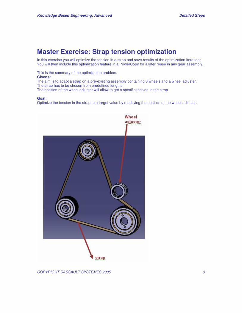
Master Exercise: Strap tension optimization In this exercise you will optimize the tension in a strap and save results of the optimization iterations. You will then include this optimization feature in a PowerCopy for a later reuse in any gear assembly. This is the summary of the optimization problem. Givens: The aim is to adapt a strap on a pre-existing assembly containing 3 wheels and a wheel adjuster. The strap has to be chosen from predefined lengths. The position of the wheel adjuster will allow to get a specific tension in the strap. Goal: Optimize the tension in the strap to a target value by modifying the position of the wheel adjuster.

Knowledge Based Engineering: Advanced Detailed Steps
COPYRIGHT DASSAULT SYSTEMES 2005 4
Step (1): Define and run the optimization 1.1 - Define the optimization in Problem tab.
• Open \…\Data\Start\Strap.CATPart document located in Student\Data\Strap directory. • Go to PEO workbench. • Click the Optimize icon. The Optimization editor panel displays. Go to Problem tab. • Select in the Optimized parameter field the parameter TENSION using the button Select.
• Select in the Optimization type Target value type of optimisation. • Click in the Target value field and enter with 1000N. • Click Edit list button in the Free parameters field. The Choose the free parameters for the
optimisation algorithm panel appears. • Select x_adjuster in the Parameters window then click the arrow to put the parameter in the
Free Parameters for Optimisation window as shown on the picture below. Click OK.
• x_adjuster appears in the Free parameters field of the Optimization panel. Select it then click
Edit ranges and step button. Specify 1mm as the Inferior Range, 200mm as the Superior Range and 0.5mm as the Step for x_adjuster. Click OK.
Knowledge Based Engineering: Advanced Detailed Steps
COPYRIGHT DASSAULT SYSTEMES 2005 5
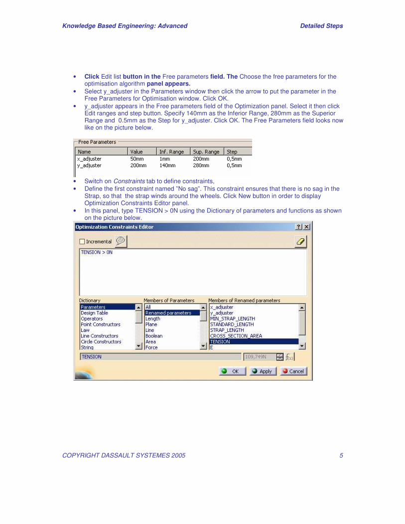
• Click Edit list button in the Free parameters field. The Choose the free parameters for the optimisation algorithm panel appears.
• Select y_adjuster in the Parameters window then click the arrow to put the parameter in the Free Parameters for Optimisation window. Click OK.
• y_adjuster appears in the Free parameters field of the Optimization panel. Select it then click Edit ranges and step button. Specify 140mm as the Inferior Range, 280mm as the Superior Range and 0.5mm as the Step for y_adjuster. Click OK. The Free Parameters field looks now like on the picture below.
• Switch on Constraints tab to define constraints, • Define the first constraint named ”No sag”. This constraint ensures that there is no sag in the
Strap, so that the strap winds around the wheels. Click New button in order to display Optimization Constraints Editor panel.
• In this panel, type TENSION > 0N using the Dictionary of parameters and functions as shown on the picture below.
Knowledge Based Engineering: Advanced Detailed Steps
COPYRIGHT DASSAULT SYSTEMES 2005 6
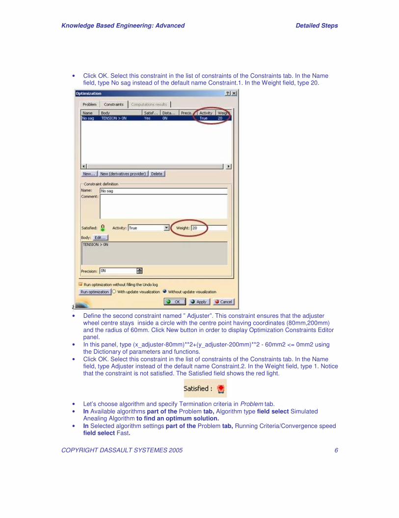
• Click OK. Select this constraint in the list of constraints of the Constraints tab. In the Name field, type No sag instead of the default name Constraint.1. In the Weight field, type 20.
• Define the second constraint named ” Adjuster”. This constraint ensures that the adjuster
wheel centre stays inside a circle with the centre point having coordinates (80mm,200mm) and the radius of 60mm. Click New button in order to display Optimization Constraints Editor panel.
• In this panel, type (x_adjuster-80mm)**2+(y_adjuster-200mm)**2 - 60mm2 <= 0mm2 using the Dictionary of parameters and functions.
• Click OK. Select this constraint in the list of constraints of the Constraints tab. In the Name field, type Adjuster instead of the default name Constraint.2. In the Weight field, type 1. Notice that the constraint is not satisfied. The Satisfied field shows the red light.
• Let’s choose algorithm and specify Termination criteria in Problem tab. • In Available algorithms part of the Problem tab, Algorithm type field select Simulated
Anealing Algorithm to find an optimum solution. • In Selected algorithm settings part of the Problem tab, Running Criteria/Convergence speed
field select Fast.
Knowledge Based Engineering: Advanced Detailed Steps
COPYRIGHT DASSAULT SYSTEMES 2005 7
• In Termination criteria part of the Problem tab, Maximum number of updates field, type 200.
• Check the Consecutive updates without improvement option and key in a value (for example 25).
• Check the Maximum time (minutes) option and key in a value (for example 5). • Let’s go to running the Optimization … • In Optimization part of the Problem tab check the option Save optimization data. • Click the Run Optimization button. In the appearing Save As panel, enter the name of the
Excel file that will contain the results of the optimisation, out.xls for example. An Optimization panel showing the progress of the computation displays.
• When the computation process is finished, this panel disappears. The panel showing the definition of the optimization problem is displayed. If you go to the Constraints tab, you can notice that after the computation”Adjuster” constraint is still not satisfied.
• Click Apply then OK button. • In the specification tree select the optimization problem node, right click and select
Properties. Rename the optimization problem to Strap tension. You can compare the result of the definition with Strap_OptimProblem.CATPart in Result directory.

Knowledge Based Engineering: Advanced Detailed Steps
COPYRIGHT DASSAULT SYSTEMES 2005 8
Step (2): Analyze the results • Analyze the results of optimization in Computation results tab. • Double-click Strap tension node to open the Optimization editor panel. In Curves part of
Computation results tab, click Show curves button. The Plot window displays. • Select TENSION in the right-hand side of the Plot window, the parameter becomes the
ordinate. • Select the TENSION curve, right click and select Only visible in the contextual menu. Only the
TENSION curve is displayed.
• Zoom on the curve, analyze the behaviour of the curve then close the Plot window. • In Settings of the results sort part of Computation results tab, click Lexicographic sort option.
See how the results are presented now. The evaluation step corresponding to the best value of TENSION parameter is now first in the list.
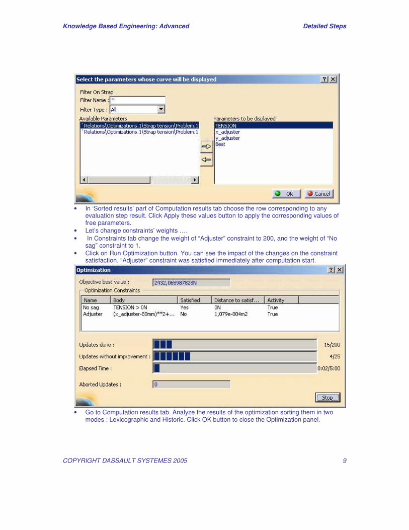
• Click on Select displayed parameters button. ‘Select the parameters whose curve will be displayed’ panel appears. Choose x_adjuster, y_adjuster, Best and TENSION in the list of Available Parameters and, using the arrow, put them in the list Parameters to be displayed as shown on the picture below. Click OK.
Knowledge Based Engineering: Advanced Detailed Steps
COPYRIGHT DASSAULT SYSTEMES 2005 9
• In ‘Sorted results’ part of Computation results tab choose the row corresponding to any
evaluation step result. Click Apply these values button to apply the corresponding values of free parameters.
• Let’s change constraints’ weights …. • In Constraints tab change the weight of “Adjuster” constraint to 200, and the weight of “No
sag” constraint to 1. • Click on Run Optimization button. You can see the impact of the changes on the constraint
satisfaction. “Adjuster” constraint was satisfied immediately after computation start.
• Go to Computation results tab. Analyze the results of the optimization sorting them in two
modes : Lexicographic and Historic. Click OK button to close the Optimization panel.
Knowledge Based Engineering: Advanced Detailed Steps
COPYRIGHT DASSAULT SYSTEMES 2005 10
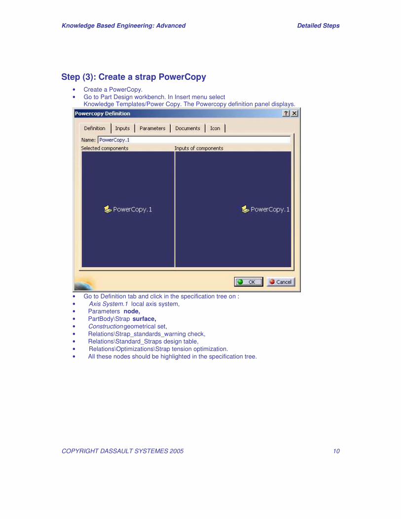
Step (3): Create a strap PowerCopy • Create a PowerCopy. • Go to Part Design workbench. In Insert menu select
Knowledge Templates/Power Copy. The Powercopy definition panel displays.
• Go to Definition tab and click in the specification tree on : • Axis System.1 local axis system, • Parameters node, • PartBody\Strap surface, • Construction geometrical set, • Relations\Strap_standards_warning check, • Relations\Standard_Straps design table, • Relations\Optimizations\Strap tension optimization. • All these nodes should be highlighted in the specification tree.
Knowledge Based Engineering: Advanced Detailed Steps
COPYRIGHT DASSAULT SYSTEMES 2005 11
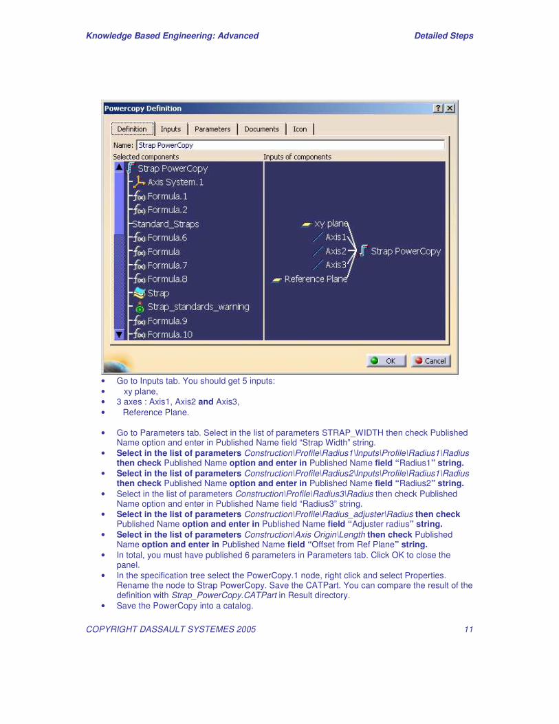
• Go to Inputs tab. You should get 5 inputs: • xy plane, • 3 axes : Axis1, Axis2 and Axis3, • Reference Plane. • Go to Parameters tab. Select in the list of parameters STRAP_WIDTH then check Published
Name option and enter in Published Name field “Strap Width” string. • Select in the list of parameters Construction\Profile\Radius1\Inputs\Profile\Radius1\Radius
then check Published Name option and enter in Published Name field “Radius1” string. • Select in the list of parameters Construction\Profile\Radius2\Inputs\Profile\Radius1\Radius
then check Published Name option and enter in Published Name field “Radius2” string. • Select in the list of parameters Construction\Profile\Radius3\Radius then check Published
Name option and enter in Published Name field “Radius3” string. • Select in the list of parameters Construction\Profile\Radius_adjuster\Radius then check
Published Name option and enter in Published Name field “Adjuster radius” string. • Select in the list of parameters Construction\Axis Origin\Length then check Published
Name option and enter in Published Name field “Offset from Ref Plane” string. • In total, you must have published 6 parameters in Parameters tab. Click OK to close the
panel. • In the specification tree select the PowerCopy.1 node, right click and select Properties.
Rename the node to Strap PowerCopy. Save the CATPart. You can compare the result of the definition with Strap_PowerCopy.CATPart in Result directory.
• Save the PowerCopy into a catalog.
Knowledge Based Engineering: Advanced Detailed Steps
COPYRIGHT DASSAULT SYSTEMES 2005 12
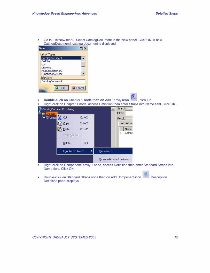
• Go to File/New menu. Select CatalogDocument in the New panel. Click OK. A new CatalogDocument1.catalog document is displayed.
• Double-click on Chapter.1 node then on Add Family icon. , click OK. • Right-click on Chapter.1 node, access Definition then enter Straps into Name field. Click OK.
• Right-click on ComponentFamily.1 node, access Definition then enter Standard Straps into
Name field. Click OK.
• Double-click on Standard Straps node then on Add Component icon . Description Definition panel displays.
Knowledge Based Engineering: Advanced Detailed Steps
COPYRIGHT DASSAULT SYSTEMES 2005 13
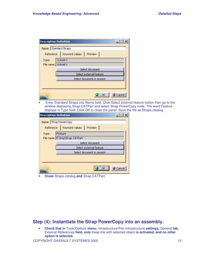
• Enter Standard Straps into Name field. Click Select external feature button then go to the
window displaying Strap.CATPart and select Strap PowerCopy node. The word Feature displays in Type field. Click OK to close the panel. Save the file as Straps.catalog.
• Close Straps.catalog and Strap.CATPart.
Step (4): Instantiate the Strap PowerCopy into an assembly. • Check that in Tools/Options menu, Infrastructure/Part Infrastructure settings, General tab,
External References field, only Keep link with selected object is activated, and no other option is selected.
Knowledge Based Engineering: Advanced Detailed Steps
COPYRIGHT DASSAULT SYSTEMES 2005 14
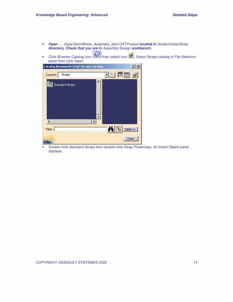
• Open \…\Data\Start\Wheel_Assembly_start.CATProduct located in Student\Data\Strap directory. Check that you are in Assembly Design workbench.
• Click Browser Catalog icon then select icon . Select Straps.catalog in File Selection panel then click Open.
• Double-click Standard Straps then double-click Strap Powercopy. An Insert Object panel
displays.
Knowledge Based Engineering: Advanced Detailed Steps
COPYRIGHT DASSAULT SYSTEMES 2005 15
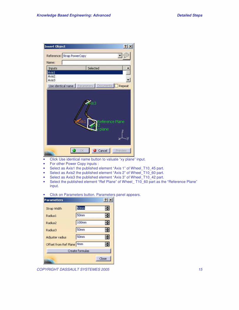
• Click Use identical name button to valuate “xy plane” input. • For other Power Copy inputs : • Select as Axis1 the published element “Axis 1” of Wheel_T10_45 part. • Select as Axis2 the published element “Axis 2” of Wheel_T10_60 part. • Select as Axis3 the published element “Axis 3” of Wheel_T10_42 part. • Select the published element “Ref Plane” of Wheel_ T10_60 part as the “Reference Plane”
input. • Click on Parameters button. Parameters panel appears.

Knowledge Based Engineering: Advanced Detailed Steps
COPYRIGHT DASSAULT SYSTEMES 2005 16
• Go to for Radius1 value window, right click and select Edit formula in the contextual menu. Formula Editor : Radius1 panel appears.
• Expand Wheel_T10_45 part node, click DIAMETRE_EXT parameter under Parameters node
and type “/2” to obtain in the editor the formula : `Part\External Parameters\DIAMETRE_EXT` /2 as shown on the picture below.
• Edit the formula `External Parameters\DIAMETRE_EXT.1` /2 for Radius2 value using the
parameter DIAMETRE_EXT of Wheel_T10_60 part.

Knowledge Based Engineering: Advanced Detailed Steps
COPYRIGHT DASSAULT SYSTEMES 2005 17
• Edit the formula `Part\External Parameters\DIAMETRE_EXT.2` /2 for Radius3 value using
the parameter DIAMETRE_EXT of Wheel_T10_42 part. • Modify the value of Strap Width parameter to 60mm. Now Parameters panel is filled as
shown on the picture below:
• Click Close button. • Click OK in Insert Object panel to instanciate the Power Copy. • The warning panel (coming from Strap_stanards_warning check) appears displaying the
message “strap is short !!! chose another one” . Click OK.

Knowledge Based Engineering: Advanced Detailed Steps
COPYRIGHT DASSAULT SYSTEMES 2005 18
• Rename the new created part as “Strap Instanciated” and save it. • Go to “Standard_Straps” Design Table node under Relations node of Strap Instanciated
part . Double-click on it to open the Design Table. Select the configuration N°10. Click OK.
• This configuration gives a strap’s length which is greater than the minimum required for this
wheels configuration. The Strap_standards_warning check light turns now to green.

Knowledge Based Engineering: Advanced Detailed Steps
COPYRIGHT DASSAULT SYSTEMES 2005 19
• Double click on the root node of the specification tree. Create a coincidence constraint between the wheel adjuster axis and the axis of the strap. To do this, click Coincidence
Constraint icon then click the wheel adjuster axis and the axis of the strap in the 3D. Update the assembly.
• Go to root assembly level then to Assembly Design workbench. Run optimization in the
assembly context • Activate Strap Instanciated part. Expand Optimizations node under Relations node. • Double-click on Strap tension node to open Optimization panel then click Run
Optimization node. • Once the optimized value is obtained (see current best value ), activate the
Wheel_Assembly product. • Update the Assembly.
Knowledge Based Engineering: Advanced Detailed Steps
COPYRIGHT DASSAULT SYSTEMES 2005 20
Step (4): Instantiate the Strap PowerCopy into an assembly. • Check that in Tools/Options menu, Infrastructure/Part Infrastructure settings, General tab,
External References field, only Keep link with selected object is activated, and no other option is selected.
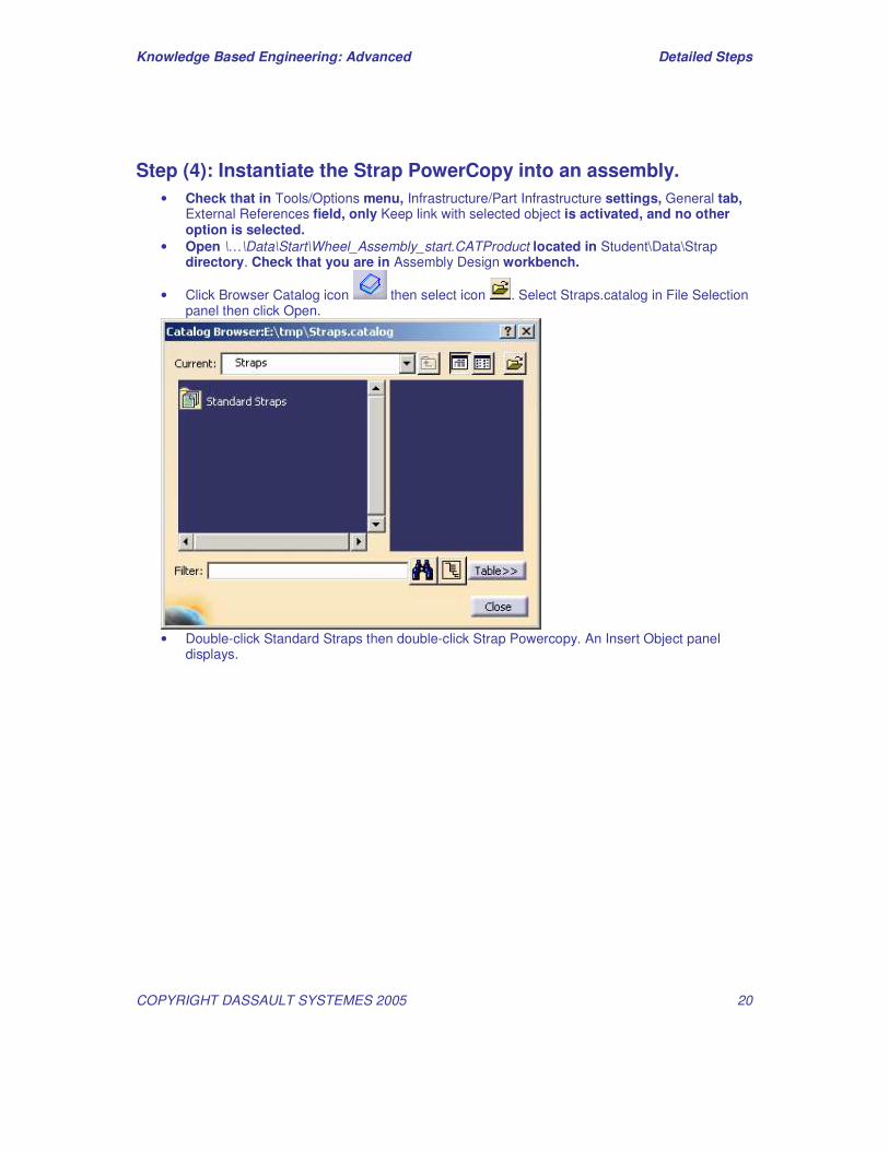
• Open \…\Data\Start\Wheel_Assembly_start.CATProduct located in Student\Data\Strap directory. Check that you are in Assembly Design workbench.
• Click Browser Catalog icon then select icon . Select Straps.catalog in File Selection panel then click Open.
• Double-click Standard Straps then double-click Strap Powercopy. An Insert Object panel
displays.

Knowledge Based Engineering: Advanced Detailed Steps
COPYRIGHT DASSAULT SYSTEMES 2005 21
• Click Use identical name button to valuate “xy plane” input. • For other Power Copy inputs : • Select as Axis1 the published element “Axis 1” of Wheel_T10_45 part. • Select as Axis2 the published element “Axis 2” of Wheel_T10_60 part. • Select as Axis3 the published element “Axis 3” of Wheel_T10_42 part. • Select the published element “Ref Plane” of Wheel_ T10_60 part as the “Reference Plane”
input. • Click on Parameters button. Parameters panel appears.
Knowledge Based Engineering: Advanced Detailed Steps
COPYRIGHT DASSAULT SYSTEMES 2005 22
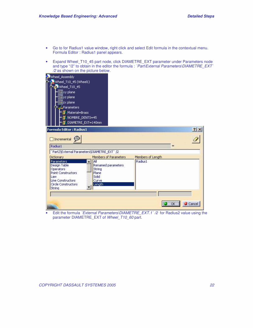
• Go to for Radius1 value window, right click and select Edit formula in the contextual menu. Formula Editor : Radius1 panel appears.
• Expand Wheel_T10_45 part node, click DIAMETRE_EXT parameter under Parameters node
and type “/2” to obtain in the editor the formula : `Part\External Parameters\DIAMETRE_EXT` /2 as shown on the picture below.
• Edit the formula `External Parameters\DIAMETRE_EXT.1` /2 for Radius2 value using the
parameter DIAMETRE_EXT of Wheel_T10_60 part.
Knowledge Based Engineering: Advanced Detailed Steps
COPYRIGHT DASSAULT SYSTEMES 2005 23
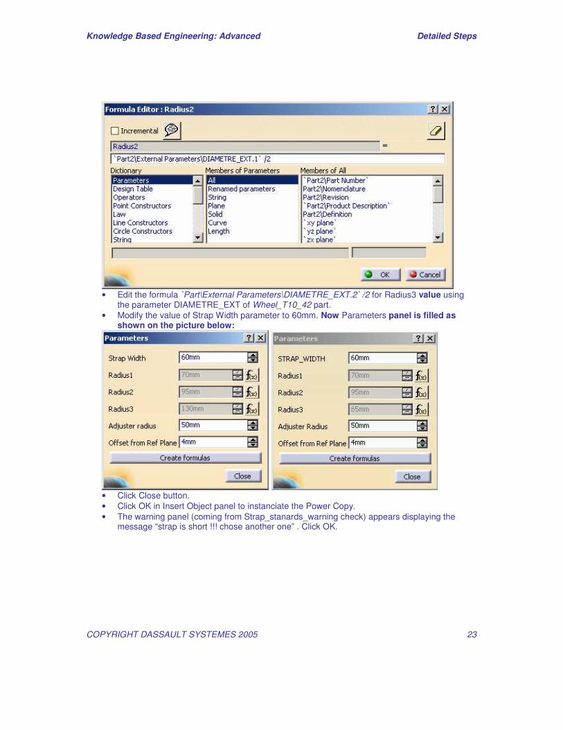
• Edit the formula `Part\External Parameters\DIAMETRE_EXT.2` /2 for Radius3 value using
the parameter DIAMETRE_EXT of Wheel_T10_42 part. • Modify the value of Strap Width parameter to 60mm. Now Parameters panel is filled as
shown on the picture below:
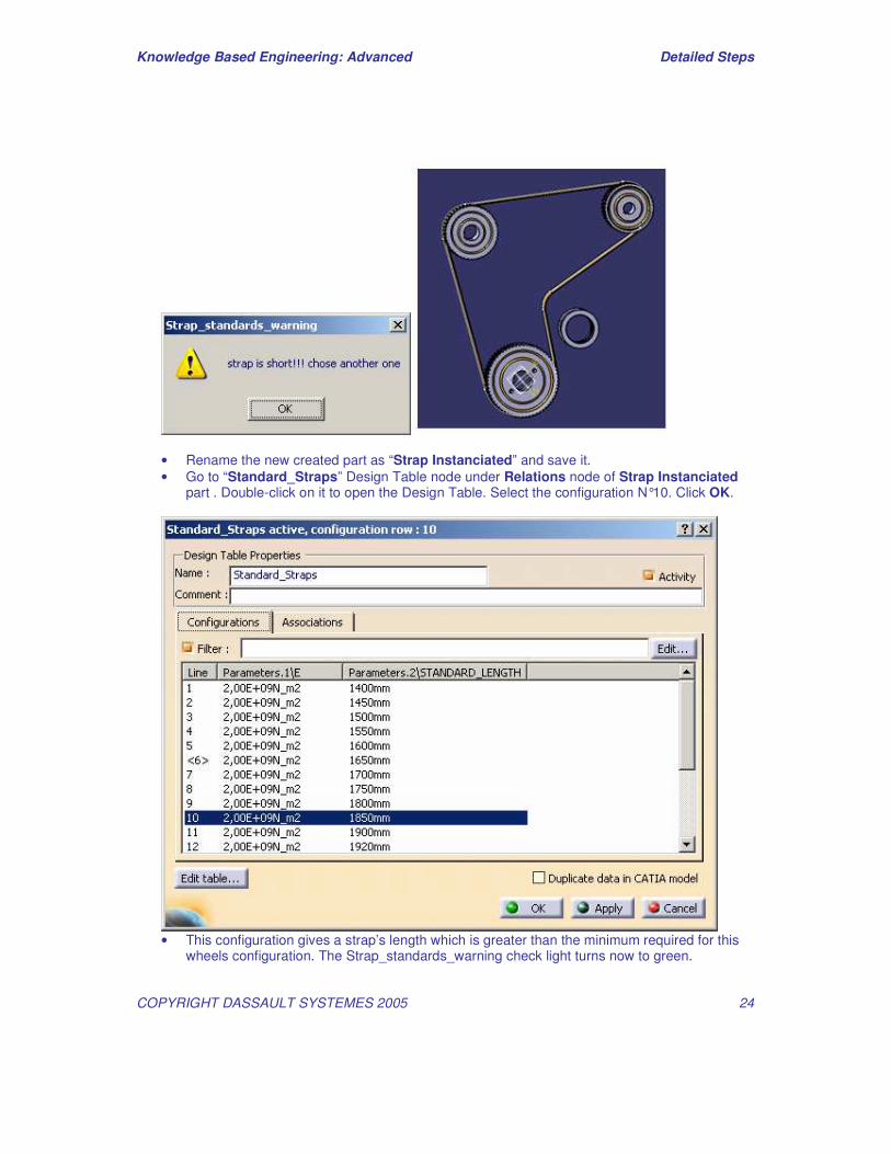
• Click Close button. • Click OK in Insert Object panel to instanciate the Power Copy. • The warning panel (coming from Strap_stanards_warning check) appears displaying the
message “strap is short !!! chose another one” . Click OK.
Knowledge Based Engineering: Advanced Detailed Steps
COPYRIGHT DASSAULT SYSTEMES 2005 24
• Rename the new created part as “Strap Instanciated” and save it. • Go to “Standard_Straps” Design Table node under Relations node of Strap Instanciated
part . Double-click on it to open the Design Table. Select the configuration N°10. Click OK.
• This configuration gives a strap’s length which is greater than the minimum required for this
wheels configuration. The Strap_standards_warning check light turns now to green.
Knowledge Based Engineering: Advanced Detailed Steps
COPYRIGHT DASSAULT SYSTEMES 2005 25
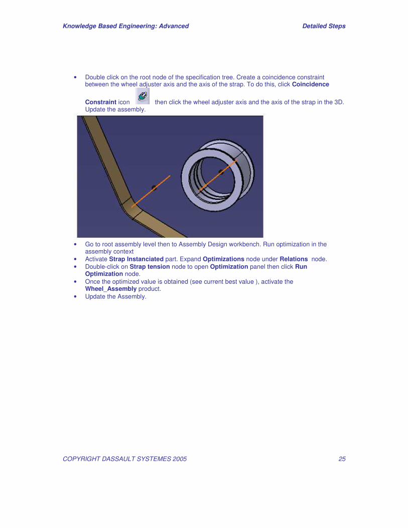
• Double click on the root node of the specification tree. Create a coincidence constraint between the wheel adjuster axis and the axis of the strap. To do this, click Coincidence
Constraint icon then click the wheel adjuster axis and the axis of the strap in the 3D. Update the assembly.
• Go to root assembly level then to Assembly Design workbench. Run optimization in the
assembly context • Activate Strap Instanciated part. Expand Optimizations node under Relations node. • Double-click on Strap tension node to open Optimization panel then click Run
Optimization node. • Once the optimized value is obtained (see current best value ), activate the
Wheel_Assembly product. • Update the Assembly.