knife cutter
TRANSCRIPT
Lab on a Chip
Cite this: DOI: 10.1039/c0xx00000x
www.rsc.org/loc
Dynamic Article Links ►
TECHNICAL INNOVATION
This journal is © The Royal Society of Chemistry [year] [journal], [year], [vol], 00–00 | 1
Xurography Actuated Valving For Centrifugal Flow Control
David J. Kinahana,b
*, Philip L. Earlya,b
, Abhishek Vembadia,c
, Eoghan MacNamarad,
Niamh A. Kilcawleya,b
, Thomas Glennond, Dermot Diamond
d, Dermot Brabazon
c and Jens Ducrée*
a,b
Received (in XXX, XXX) Xth XXXXXXXXX 20XX, Accepted Xth XXXXXXXXX 20XX
DOI: 10.1039/b000000x 5
We introduce a novel instrument controlled valving scheme for centrifugal platforms which is based upon
xurography. In a first approach, which is akin to previously presented event-triggered flow control, the
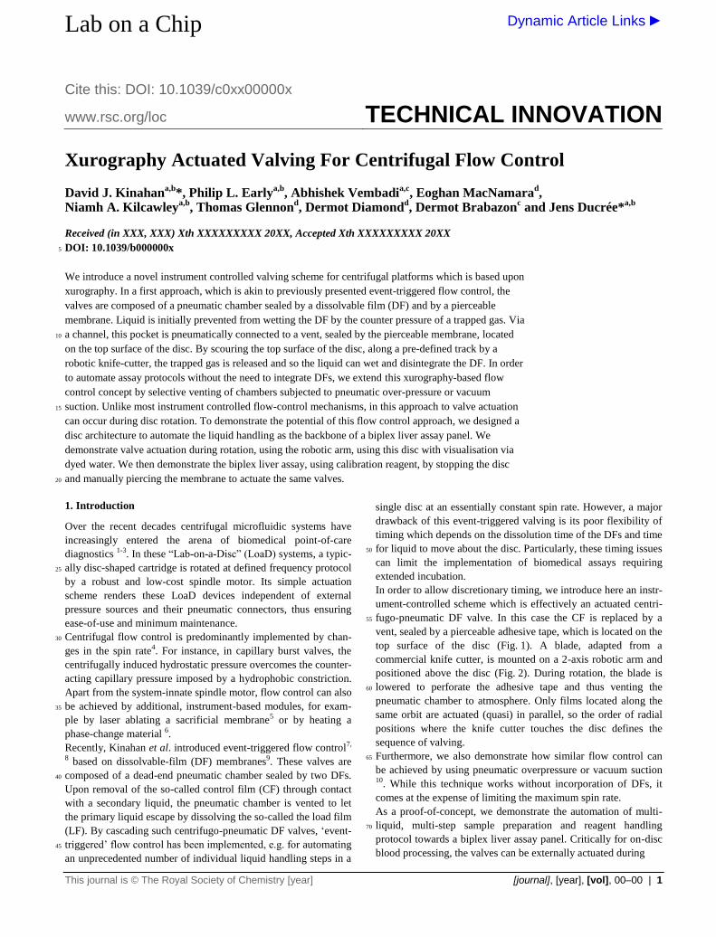
valves are composed of a pneumatic chamber sealed by a dissolvable film (DF) and by a pierceable
membrane. Liquid is initially prevented from wetting the DF by the counter pressure of a trapped gas. Via
a channel, this pocket is pneumatically connected to a vent, sealed by the pierceable membrane, located 10
on the top surface of the disc. By scouring the top surface of the disc, along a pre-defined track by a
robotic knife-cutter, the trapped gas is released and so the liquid can wet and disintegrate the DF. In order
to automate assay protocols without the need to integrate DFs, we extend this xurography-based flow
control concept by selective venting of chambers subjected to pneumatic over-pressure or vacuum
suction. Unlike most instrument controlled flow-control mechanisms, in this approach to valve actuation 15
can occur during disc rotation. To demonstrate the potential of this flow control approach, we designed a
disc architecture to automate the liquid handling as the backbone of a biplex liver assay panel. We
demonstrate valve actuation during rotation, using the robotic arm, using this disc with visualisation via
dyed water. We then demonstrate the biplex liver assay, using calibration reagent, by stopping the disc
and manually piercing the membrane to actuate the same valves. 20
1. Introduction
Over the recent decades centrifugal microfluidic systems have
increasingly entered the arena of biomedical point-of-care
diagnostics 1-3. In these “Lab-on-a-Disc” (LoaD) systems, a typic-
ally disc-shaped cartridge is rotated at defined frequency protocol 25
by a robust and low-cost spindle motor. Its simple actuation
scheme renders these LoaD devices independent of external
pressure sources and their pneumatic connectors, thus ensuring
ease-of-use and minimum maintenance.
Centrifugal flow control is predominantly implemented by chan-30
ges in the spin rate4. For instance, in capillary burst valves, the
centrifugally induced hydrostatic pressure overcomes the counter-
acting capillary pressure imposed by a hydrophobic constriction.
Apart from the system-innate spindle motor, flow control can also
be achieved by additional, instrument-based modules, for exam-35
ple by laser ablating a sacrificial membrane5 or by heating a
phase-change material 6.
Recently, Kinahan et al. introduced event-triggered flow control7,
8 based on dissolvable-film (DF) membranes9. These valves are
composed of a dead-end pneumatic chamber sealed by two DFs. 40
Upon removal of the so-called control film (CF) through contact
with a secondary liquid, the pneumatic chamber is vented to let
the primary liquid escape by dissolving the so-called the load film
(LF). By cascading such centrifugo-pneumatic DF valves, ‘event-
triggered’ flow control has been implemented, e.g. for automating 45
an unprecedented number of individual liquid handling steps in a
single disc at an essentially constant spin rate. However, a major
drawback of this event-triggered valving is its poor flexibility of
timing which depends on the dissolution time of the DFs and time
for liquid to move about the disc. Particularly, these timing issues 50
can limit the implementation of biomedical assays requiring
extended incubation.
In order to allow discretionary timing, we introduce here an instr-
ument-controlled scheme which is effectively an actuated centri-
fugo-pneumatic DF valve. In this case the CF is replaced by a 55
vent, sealed by a pierceable adhesive tape, which is located on the
top surface of the disc (Fig. 1). A blade, adapted from a
commercial knife cutter, is mounted on a 2-axis robotic arm and
positioned above the disc (Fig. 2). During rotation, the blade is
lowered to perforate the adhesive tape and thus venting the 60
pneumatic chamber to atmosphere. Only films located along the
same orbit are actuated (quasi) in parallel, so the order of radial
positions where the knife cutter touches the disc defines the
sequence of valving.
Furthermore, we also demonstrate how similar flow control can 65
be achieved by using pneumatic overpressure or vacuum suction 10. While this technique works without incorporation of DFs, it
comes at the expense of limiting the maximum spin rate.
As a proof-of-concept, we demonstrate the automation of multi-
liquid, multi-step sample preparation and reagent handling 70
protocol towards a biplex liver assay panel. Critically for on-disc
blood processing, the valves can be externally actuated during
2 | Journal Name, [year], [vol], 00–00 This journal is © The Royal Society of Chemistry [year]
Figure 1: Operation of the xurography-enabled DF valve. (a) The valve consists of a pneumatic chamber with two outlets closed by a DF tab and PSA. (b) The gas pocket trapped between the meniscus of the incoming liquid and these outlets initially prevents the wetting of the DF. (c) To open the valve, a knife blade mounted on a robotic arm (cf. Fig. 2) scours the top of the disc, and thereby piercing the PSA. (d) As the gas pocket decompresses, the DF is
wetted and dissolves to clear the passage of liquid to the outlet. 5
rotation, thus ensuring efficient plasma extraction. This highly
controllable valving scheme, where liquid handling steps at any
location on the disc can be controlled through interaction with its
external surface, represents a viable path towards large-scale
integration (LSI) and automation of multiplex bio-assays. 10
2. Experimental
2.1 Manufacture of Robotic Arm
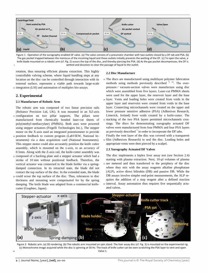
The robotic arm was composed of two linear precision rails
(Reliance Precision Ltd, UK). It was mounted in an XZ-axis
configuration on two pillar supports. The pillars were 15
manufactured from chemically bonded laser-cut sheets of
poly(methyl-methacrylate) (PMMA). Both axes were powered
using stepper actuators (Firgelli Technologies Inc.). The stepper
motor on the X-axis used an integrated potentiometer to provide
position feedback to custom program (LabVIEW, National In-20
struments) via a data acquisition card (National Instruments).
This stepper motor could also accurately position the knife cutter
assembly, which is mounted on the x-axis, to an accuracy of
0.5mm. Along with the Z-axis rail, the knife-cutter assembly was
composed of a backing plate and a stepper actuator which had a 25
stroke of 10 mm without positional feedback. Therefore, the
vertical actuator was connected to the blade holder via a spring-
damped connection. In its retracted state, the blade did not
contact the top surface of the disc. In the extended state, the blade
could scour the top surface of the disc. Thus, tolerances in disc 30
thickness and mounting were compensated for by the spring
damping. The knife blade was adapted from a commercial knife-
cutter (Graphtec, Japan).
2.2 Disc Manufacture
The discs are manufactured using multilayer polymer fabrication 35
methods using methods previously described 7, 11. The over-
pressure / vacuum-suction valves were manufacture using disc
which were assembled from five layers. Laser-cut PMMA sheets
were used for the upper layer, the reservoir layer and the base
layer. Vents and loading holes were created from voids in the 40
upper layer and reservoirs were created from voids in the base
layer. Connecting microchannels were created on the upper and
lower pressure sensitive adhesive (PSA) (Adhesives Research,
Limerick, Ireland) from voids created by a knife-cutter. The
stacking of the two PSA layers permitted microchannels cros-45
sings. The discs for demonstrating xurography actuated DF
valves were manufactured from four PMMA and four PSA layers
as previously described 7 in order to incorporate the DF tabs.
Finally the vent layer of the disc was covered with a transparent
film (Adhesives Research) to seal the disc. Loading holes and 50
appropriate vents were then pierced by a scalpel.
2.3 Xurography Actuated DF Valves
The disc implements a biplex liver assay test (see Section 2.4)
starting with plasma extraction. Next, 10-µl volumes of plasma
are metered and then transferred to the periphery of the disc 55
where they mix with the assay reagents alkaline phosphatase
(ALP), active direct bilirubin (DB) and passive DB. While the
DB assays involve simpler end-point measurements, the ALP re-
quires the addition of a stop reagent after a defined reaction
interval. Assay automation thus requires five sequentially actu-60
ated valves.
Figure 2: Robotic arm. (a) 3D rendering. (b) The robotic arm mounted on spin stand. The liver assay disc (cf. Fig. 3) is mounted on the experimental rig.
(c) Monochrome image acquired while the disc is spinning at 50 Hz. The track of knife cutter can be seen scratching the PSA layer to vent and open Valve 1. 65
This journal is © The Royal Society of Chemistry [2013] Lab Chip, 2013, [vol], 00–00 | 3
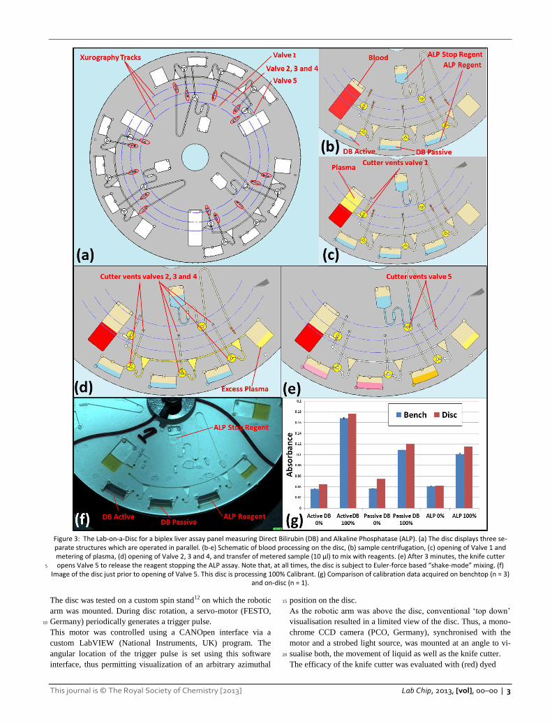
Figure 3: The Lab-on-a-Disc for a biplex liver assay panel measuring Direct Bilirubin (DB) and Alkaline Phosphatase (ALP). (a) The disc displays three se-parate structures which are operated in parallel. (b-e) Schematic of blood processing on the disc, (b) sample centrifugation, (c) opening of Valve 1 and metering of plasma, (d) opening of Valve 2, 3 and 4, and transfer of metered sample (10 µl) to mix with reagents. (e) After 3 minutes, the knife cutter opens Valve 5 to release the reagent stopping the ALP assay. Note that, at all times, the disc is subject to Euler-force based “shake-mode” mixing. (f) 5
Image of the disc just prior to opening of Valve 5. This disc is processing 100% Calibrant. (g) Comparison of calibration data acquired on benchtop (n = 3) and on-disc (n = 1).
The disc was tested on a custom spin stand12 on which the robotic
arm was mounted. During disc rotation, a servo-motor (FESTO,
Germany) periodically generates a trigger pulse. 10
This motor was controlled using a CANOpen interface via a
custom LabVIEW (National Instruments, UK) program. The
angular location of the trigger pulse is set using this software
interface, thus permitting visualization of an arbitrary azimuthal
position on the disc. 15
As the robotic arm was above the disc, conventional ‘top down’
visualisation resulted in a limited view of the disc. Thus, a mono-
chrome CCD camera (PCO, Germany), synchronised with the
motor and a strobed light source, was mounted at an angle to vi-
sualise both, the movement of liquid as well as the knife cutter. 20
The efficacy of the knife cutter was evaluated with (red) dyed
4 | Journal Name, [year], [vol], 00–00 This journal is © The Royal Society of Chemistry [year]
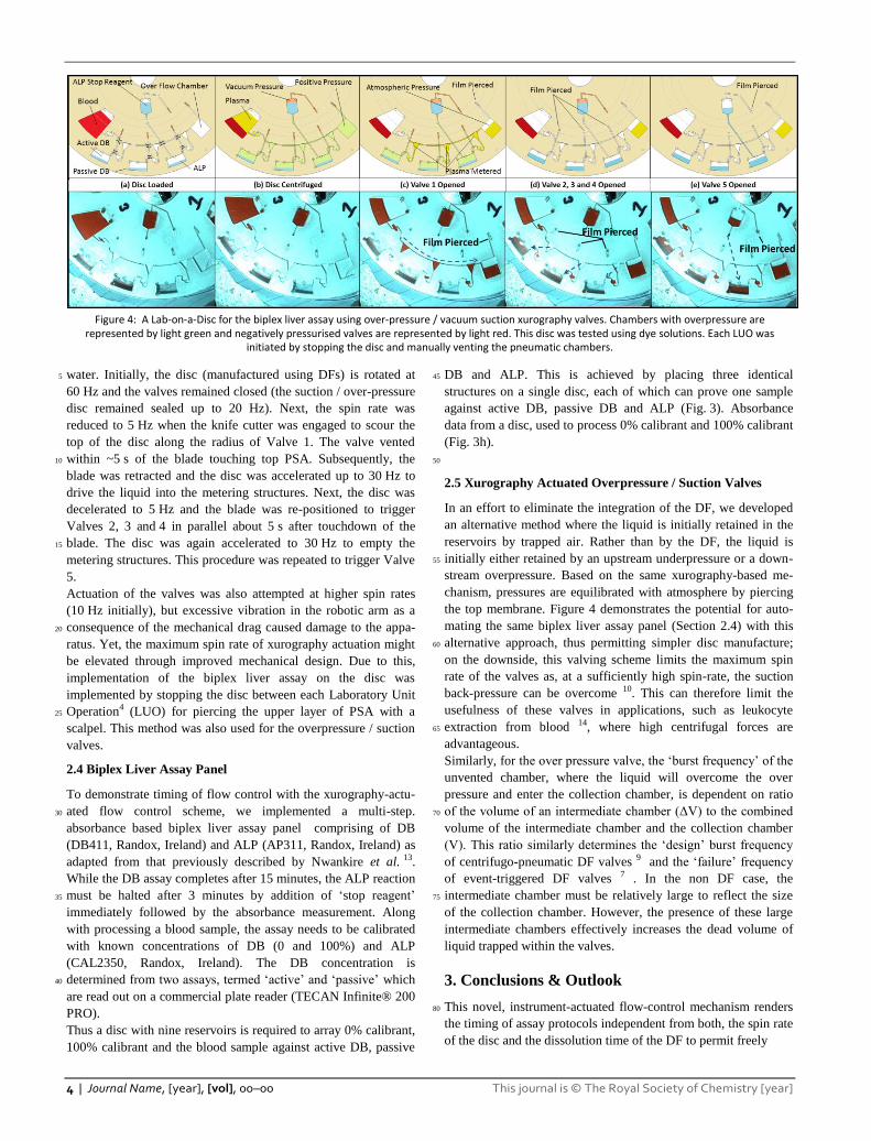
Figure 4: A Lab-on-a-Disc for the biplex liver assay using over-pressure / vacuum suction xurography valves. Chambers with overpressure are
represented by light green and negatively pressurised valves are represented by light red. This disc was tested using dye solutions. Each LUO was initiated by stopping the disc and manually venting the pneumatic chambers.
water. Initially, the disc (manufactured using DFs) is rotated at 5
60 Hz and the valves remained closed (the suction / over-pressure
disc remained sealed up to 20 Hz). Next, the spin rate was
reduced to 5 Hz when the knife cutter was engaged to scour the
top of the disc along the radius of Valve 1. The valve vented
within ~5 s of the blade touching top PSA. Subsequently, the 10
blade was retracted and the disc was accelerated up to 30 Hz to
drive the liquid into the metering structures. Next, the disc was
decelerated to 5 Hz and the blade was re-positioned to trigger
Valves 2, 3 and 4 in parallel about 5 s after touchdown of the
blade. The disc was again accelerated to 30 Hz to empty the 15
metering structures. This procedure was repeated to trigger Valve
5.
Actuation of the valves was also attempted at higher spin rates
(10 Hz initially), but excessive vibration in the robotic arm as a
consequence of the mechanical drag caused damage to the appa-20
ratus. Yet, the maximum spin rate of xurography actuation might
be elevated through improved mechanical design. Due to this,
implementation of the biplex liver assay on the disc was
implemented by stopping the disc between each Laboratory Unit
Operation4 (LUO) for piercing the upper layer of PSA with a 25
scalpel. This method was also used for the overpressure / suction
valves.
2.4 Biplex Liver Assay Panel
To demonstrate timing of flow control with the xurography-actu-
ated flow control scheme, we implemented a multi-step. 30
absorbance based biplex liver assay panel comprising of DB
(DB411, Randox, Ireland) and ALP (AP311, Randox, Ireland) as
adapted from that previously described by Nwankire et al. 13.
While the DB assay completes after 15 minutes, the ALP reaction
must be halted after 3 minutes by addition of ‘stop reagent’ 35
immediately followed by the absorbance measurement. Along
with processing a blood sample, the assay needs to be calibrated
with known concentrations of DB (0 and 100%) and ALP
(CAL2350, Randox, Ireland). The DB concentration is
determined from two assays, termed ‘active’ and ‘passive’ which 40
are read out on a commercial plate reader (TECAN Infinite® 200
PRO).
Thus a disc with nine reservoirs is required to array 0% calibrant,
100% calibrant and the blood sample against active DB, passive
DB and ALP. This is achieved by placing three identical 45
structures on a single disc, each of which can prove one sample
against active DB, passive DB and ALP (Fig. 3). Absorbance
data from a disc, used to process 0% calibrant and 100% calibrant
(Fig. 3h).
50
2.5 Xurography Actuated Overpressure / Suction Valves
In an effort to eliminate the integration of the DF, we developed
an alternative method where the liquid is initially retained in the
reservoirs by trapped air. Rather than by the DF, the liquid is
initially either retained by an upstream underpressure or a down-55
stream overpressure. Based on the same xurography-based me-
chanism, pressures are equilibrated with atmosphere by piercing
the top membrane. Figure 4 demonstrates the potential for auto-
mating the same biplex liver assay panel (Section 2.4) with this
alternative approach, thus permitting simpler disc manufacture; 60
on the downside, this valving scheme limits the maximum spin
rate of the valves as, at a sufficiently high spin-rate, the suction
back-pressure can be overcome 10. This can therefore limit the
usefulness of these valves in applications, such as leukocyte
extraction from blood 14, where high centrifugal forces are 65
advantageous.
Similarly, for the over pressure valve, the ‘burst frequency’ of the
unvented chamber, where the liquid will overcome the over
pressure and enter the collection chamber, is dependent on ratio
of the volume of an intermediate chamber (ΔV) to the combined 70
volume of the intermediate chamber and the collection chamber
(V). This ratio similarly determines the ‘design’ burst frequency
of centrifugo-pneumatic DF valves 9 and the ‘failure’ frequency
of event-triggered DF valves 7 . In the non DF case, the
intermediate chamber must be relatively large to reflect the size 75
of the collection chamber. However, the presence of these large
intermediate chambers effectively increases the dead volume of
liquid trapped within the valves.
3. Conclusions & Outlook
This novel, instrument-actuated flow-control mechanism renders 80
the timing of assay protocols independent from both, the spin rate
of the disc and the dissolution time of the DF to permit freely
This journal is © The Royal Society of Chemistry [2013] Lab Chip, 2013, [vol], 00–00 | 5
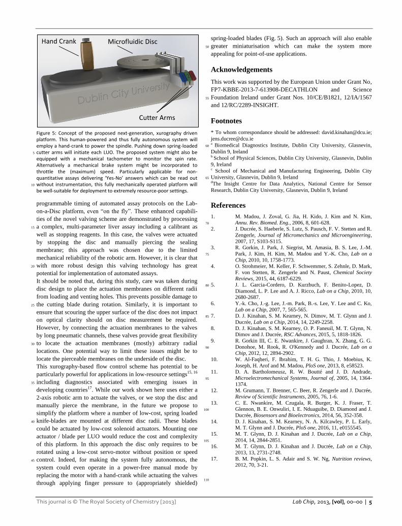
Figure 5: Concept of the proposed next-generation, xurography driven platform. This human-powered and thus fully autonomous system will employ a hand-crank to power the spindle. Pushing down spring-loaded cutter arms will initiate each LUO. The proposed system might also be 5
equipped with a mechanical tachometer to monitor the spin rate. Alternatively a mechanical brake system might be incorporated to throttle the (maximum) speed. Particularly applicable for non-quantitative assays delivering ‘Yes-No’ answers which can be read out without instrumentation, this fully mechanically operated platform will 10
be well-suitable for deployment to extremely resource-poor settings.
programmable timing of automated assay protocols on the Lab-
on-a-Disc platform, even “on the fly”. These enhanced capabili-
ties of the novel valving scheme are demonstrated by processing
a complex, multi-parameter liver assay including a calibrant as 15
well as stopping reagents. In this case, the valves were actuated
by stopping the disc and manually piercing the sealing
membrane; this approach was chosen due to the limited
mechanical reliability of the robotic arm. However, it is clear that
with more robust design this valving technology has great 20
potential for implementation of automated assays.
It should be noted that, during this study, care was taken during
disc design to place the actuation membranes on different radii
from loading and venting holes. This prevents possible damage to
the cutting blade during rotation. Similarly, it is important to 25
ensure that scouring the upper surface of the disc does not impact
on optical clarity should on disc measurement be required.
However, by connecting the actuation membranes to the valves
by long pneumatic channels, these valves provide great flexibility
to locate the actuation membranes (mostly) arbitrary radial 30
locations. One potential way to limit these issues might be to
locate the pierceable membranes on the underside of the disc.
This xurography-based flow control scheme has potential to be
particularly powerful for applications in low-resource settings15, 16
including diagnostics associated with emerging issues in 35
developing countries17. While our work shown here uses either a
2-axis robotic arm to actuate the valves, or we stop the disc and
manually pierce the membrane, in the future we propose to
simplify the platform where a number of low-cost, spring loaded
knife-blades are mounted at different disc radii. These blades 40
could be actuated by low-cost solenoid actuators. Mounting one
actuator / blade per LUO would reduce the cost and complexity
of this platform. In this approach the disc only requires to be
rotated using a low-cost servo-motor without position or speed
control. Indeed, for making the system fully autonomous, the 45
system could even operate in a power-free manual mode by
replacing the motor with a hand-crank while actuating the valves
through applying finger pressure to (appropriately shielded)
spring-loaded blades (Fig. 5). Such an approach will also enable
greater miniaturisation which can make the system more 50
appealing for point-of-use applications.
Acknowledgements
This work was supported by the European Union under Grant No,
FP7-KBBE-2013-7-613908-DECATHLON and Science
Foundation Ireland under Grant Nos. 10/CE/B1821, 12/IA/1567 55
and 12/RC/2289-INSIGHT.
Footnotes
* To whom correspondance should be addressed: [email protected];
[email protected] a Biomedical Diagnostics Institute, Dublin City University, Glasnevin, 60
Dublin 9, Ireland b School of Physical Sciences, Dublin City University, Glasnevin, Dublin
9, Ireland c School of Mechanical and Manufacturing Engineering, Dublin City
University, Glasnevin, Dublin 9, Ireland 65
dThe Insight Centre for Data Analytics, National Centre for Sensor
Research, Dublin City University, Glasnevin, Dublin 9, Ireland
References
1. M. Madou, J. Zoval, G. Jia, H. Kido, J. Kim and N. Kim,
Annu. Rev. Biomed. Eng., 2006, 8, 601-628. 70
2. J. Ducrée, S. Haeberle, S. Lutz, S. Pausch, F. V. Stetten and R.
Zengerle, Journal of Micromechanics and Microengineering,
2007, 17, S103-S115. 3. R. Gorkin, J. Park, J. Siegrist, M. Amasia, B. S. Lee, J.-M.
Park, J. Kim, H. Kim, M. Madou and Y.-K. Cho, Lab on a 75
Chip, 2010, 10, 1758-1773. 4. O. Strohmeier, M. Keller, F. Schwemmer, S. Zehnle, D. Mark,
F. von Stetten, R. Zengerle and N. Paust, Chemical Society
Reviews, 2015, 44, 6187-6229. 5. J. L. Garcia-Cordero, D. Kurzbuch, F. Benito-Lopez, D. 80
Diamond, L. P. Lee and A. J. Ricco, Lab on a Chip, 2010, 10, 2680-2687.
6. Y.-k. Cho, J.-g. Lee, J.-m. Park, B.-s. Lee, Y. Lee and C. Ko,
Lab on a Chip, 2007, 7, 565-565. 7. D. J. Kinahan, S. M. Kearney, N. Dimov, M. T. Glynn and J. 85
Ducrée, Lab on a Chip, 2014, 14, 2249-2258.
8. D. J. Kinahan, S. M. Kearney, O. P. Faneuil, M. T. Glynn, N. Dimov and J. Ducrée, RSC Advances, 2015, 5, 1818-1826.
9. R. Gorkin III, C. E. Nwankire, J. Gaughran, X. Zhang, G. G.
Donohoe, M. Rook, R. O'Kennedy and J. Ducrée, Lab on a 90
Chip, 2012, 12, 2894-2902.
10. W. Al-Faqheri, F. Ibrahim, T. H. G. Thio, J. Moebius, K.
Joseph, H. Arof and M. Madou, PloS one, 2013, 8, e58523. 11. D. A. Bartholomeusz, R. W. Boutté and J. D. Andrade,
Microelectromechanical Systems, Journal of, 2005, 14, 1364-95
1374. 12. M. Grumann, T. Brenner, C. Beer, R. Zengerle and J. Ducrée,
Review of Scientific Instruments, 2005, 76, 1-6.
13. C. E. Nwankire, M. Czugala, R. Burger, K. J. Fraser, T. Glennon, B. E. Onwuliri, I. E. Nduaguibe, D. Diamond and J. 100
Ducrée, Biosensors and Bioelectronics, 2014, 56, 352-358.
14. D. J. Kinahan, S. M. Kearney, N. A. Kilcawley, P. L. Early, M. T. Glynn and J. Ducrée, PloS one, 2016, 11, e0155545.
15. M. T. Glynn, D. J. Kinahan and J. Ducrée, Lab on a Chip,
2014, 14, 2844-2851. 105
16. M. T. Glynn, D. J. Kinahan and J. Ducrée, Lab on a Chip,
2013, 13, 2731-2748.
17. B. M. Popkin, L. S. Adair and S. W. Ng, Nutrition reviews, 2012, 70, 3-21.
110