km4m/km4am series - practically nerded, your …dundats.mvps.org/hardware/manuals/e6734v1.5.pdf ·...
TRANSCRIPT

i
G52-M6734XD
MS-6734 (v1.X) M-ATX Mainboard
KM4M/KM4AM Series

ii
Manual Rev: 1.5Release Date: July 2004
FCC-B Radio Frequency Interference Statement
This equipment has been tested and found to comply with the limits for a class Bdigital device, pursuant to part 15 of the FCC rules. These limits are designed toprovide reasonable protection against harmful interference when the equipment isoperated in a commercial environment. This equipment generates, uses and canradiate radio frequency energy and, if not installed and used in accordance with theinstruction manual, may cause harmful interference to radio communications. Opera-tion of this equipment in a residential area is likely to cause harmful interference, inwhich case the user will be required to correct the interference at his own expense.
Notice 1The changes or modifications not expressly approved by the party responsible forcompliance could void the user’s authority to operate the equipment.
Notice 2Shielded interface cables and A.C. power cord, if any, must be used in order tocomply with the emission limits.
VOIR LA NOTICE D’INSTALLATION AVANT DE RACCORDER AU RESEAU.
Micro-Star InternationalMS-6734
This device complies with Part 15 of the FCC Rules. Operation is subject to thefollowing two conditions:(1) this device may not cause harmful interference, and(2) this device must accept any interference received, including interference thatmay cause undesired operation

iii
Copyright Notice
The material in this document is the intellectual property of MICRO-STARINTERNATIONAL. We take every care in the preparation of this document, but noguarantee is given as to the correctness of its contents. Our products are undercontinual improvement and we reserve the right to make changes without notice.
Trademarks
All trademarks are the properties of their respective owners.
AMD, Athlon™, Athlon™ XP, Thoroughbred™, and Duron™ are registered trade-marks of AMD Corporation.Intel® and Pentium® are registered trademarks of Intel Corporation.PS/2 and OS®/2 are registered trademarks of International Business MachinesCorporation.Microsoft is a registered trademark of Microsoft Corporation. Windows® 98/2000/NT/XP are registered trademarks of Microsoft Corporation.NVIDIA, the NVIDIA logo, DualNet, and nForce are registered trademarks or trade-marks of NVIDIA Corporation in the United States and/or other countries.Netware® is a registered trademark of Novell, Inc.Award® is a registered trademark of Phoenix Technologies Ltd.AMI® is a registered trademark of American Megatrends Inc.Kensington and MicroSaver are registered trademarks of the Kensington TechnologyGroup.PCMCIA and CardBus are registered trademarks of the Personal Computer MemoryCard International Association.
Revision HistoryRevision Revision History DateV1.0 First release June 2003V1.1 NB chipset with optional December 2003
KM400 / KM400A chipsetV1.2 Update 1394 & CPU FSB jumper March 2004
descriptionV1.3 White Brand version April 2004V1.4 Update CPU Description May 2004V1.5 Update JAUD1 pin definition & July 2004
CPU FSB jumper description

iv
1. Always read the safety instructions carefully.2. Keep this User’s Manual for future reference.3. Keep this equipment away from humidity.4. Lay this equipment on a reliable flat surface before setting it up.5. The openings on the enclosure are for air convection hence protects the equip-
ment from overheating. Do not cover the openings.6. Make sure the voltage of the power source and adjust properly 110/220V be-
fore connecting the equipment to the power inlet.7. Place the power cord such a way that people can not step on it. Do not place
anything over the power cord.8. Always Unplug the Power Cord before inserting any add-on card or module.9. All cautions and warnings on the equipment should be noted.10. Never pour any liquid into the opening that could damage or cause electrical
shock.11. If any of the following situations arises, get the equipment checked by a service
personnel:The power cord or plug is damaged.Liquid has penetrated into the equipment.The equipment has been exposed to moisture.The equipment has not work well or you can not get it work according toUser’s Manual.The equipment has dropped and damaged.The equipment has obvious sign of breakage.
12. Do not leave this equipment in an environment unconditioned, storagetemperature above 600 C (1400F), it may damage the equipment.
Safety Instructions
CAUTION: Danger of explosion if battery is incorrectly replaced.Replace only with the same or equivalent type recommended by themanufacturer.
Technical Support
If a problem arises with your system and no solution can be obtained from the user’smanual, please contact your place of purchase or local distributor. Alternatively,please try the following help resources for further guidance.
Visit the MSI homepage & FAQ site for technical guide, BIOS updates, driverupdates, and other information: http://www.msi.com.tw & http://www.msi.com.tw/program/service/faq/faq/esc_faq_list.php Contact our technical staff at: [email protected]
v
CONTENTSFCC-B Radio Frequency Interference Statement ........................................................ iiCopyright Notice ........................................................................................................... iiiRevision History ............................................................................................................ iiiSafety Instructions ...................................................................................................... ivTechnical Support ........................................................................................................ ivChapter 1. Getting Started ................................................................................... 1-1
Mainboard Specifications .................................................................................. 1-2Mainboard Layout .............................................................................................. 1-4
Chapter 2. Hardware Setup ................................................................................. 2-1Quick Components Guide .................................................................................. 2-4Central Processing Unit: CPU ............................................................................ 2-3
CPU Core Speed Derivation Procedure .................................................... 2-3CPU Installation Procedures for Socket 462 ............................................. 2-5Installing AMD Athlon CPU (Socket 462) Cooler Set ................................. 2-5CPU Clock Frequency Selection through BIOS ......................................... 2-6
Memory ............................................................................................................... 2-7Memory Speed/CPU FSB Support Matrix .................................................. 2-7DIMM Module Combination .......................................................................... 2-8Installing DDR Modules ............................................................................... 2-8
Power Supply ..................................................................................................... 2-9ATX 20-Pin Power Connector: CONN1 ..................................................... 2-9ATX 12V Power Connector: JPW1 ............................................................ 2-9
Back Panel ........................................................................................................ 2-10Mouse Connector ..................................................................................... 2-10Keyboard Connector ................................................................................ 2-11USB Connectors ....................................................................................... 2-11Serial Port Connector: COM 1 .................................................................. 2-12
VGA Connector ........................................................................................ 2-12IEEE1394 Port (Optional) .......................................................................... 2-12RJ-45 LAN Jack (Optional) ...................................................................... 2-13
Audio Port Connectors ............................................................................. 2-13Parallel Port Connector: LPT1 .................................................................. 2-14
Connectors ....................................................................................................... 2-15Floppy Disk Drive Connector: FDD1 ........................................................ 2-15Fan Power Connectors: CPUFA1/SYSFA1 ............................................. 2-15Hard Disk Connectors: IDE1 & IDE2 ......................................................... 2-16

vi
Serial ATA Connectors controlled by VT8237: SATA1 & SATA2 (for KM4AM only) ........................................................................... 2-17Front Panel Connectors: JFP1 & JFP2 ..................................................... 2-18CD-In Connector: JCD1 ............................................................................ 2-18Front USB Connectors: JUSB2 & JUSB3 (JUSB3 is optional) ............... 2-19IEEE 1394 Connectors: J1394_1 & J1394_2 (Optional) ......................... 2-20Front Panel Audio Connector: JAUD1 ..................................................... 2-21SPDIF-Out Connector: JSP1 ..................................................................... 2-21
Jumpers ............................................................................................................ 2-22Clear CMOS Jumper: JBAT1 .................................................................... 2-22CPU Frequency Jumpers: SW1 & SW2 ................................................... 2-22
Slots .................................................................................................................. 2-23AGP (Accelerated Graphics Port) Slot ................................................... 2-23PCI (Peripheral Component Interconnect) Slots ...................................... 2-23PCI Interrupt Request Routing .................................................................. 2-23
Chapter 3. BIOS Setup ........................................................................................... 3-1Entering Setup .................................................................................................... 3-2
Control Keys ............................................................................................... 3-2Getting Help ................................................................................................ 3-2
The Main Menu ................................................................................................... 3-3Standard CMOS Features .................................................................................. 3-5Advanced BIOS Features .................................................................................. 3-7Advanced Chipset Features ........................................................................... 3-10Integrated Peripherals ...................................................................................... 3-13Power Management Setup .............................................................................. 3-17PNP/PCI Configurations .................................................................................... 3-21PC Health Status .............................................................................................. 3-23Frequency/Voltage Control .............................................................................. 3-24Load Fail-Safe/Optimized Defaults ................................................................. 3-25Set Supervisor/User Password ...................................................................... 3-26
Chapter 4. VIA VT8237 Serial ATA RAID Introduction .................................... 4-1Introduction ......................................................................................................... 4-2BIOS Configuration ............................................................................................. 4-3Installing RAID Software & Drivers ................................................................. 4-10Using VIA RAID Tool ......................................................................................... 4-13

1 - 1
Getting Started
Thank you for purchasing the KM4M / KM4AM (MS-6734 v1.x) Micro-ATX mainboard. The KM4M / KM4AM v1.x Micro-ATX mainboard isbased on VIA® Apollo KM400/400A North Bridge & VT8235/8237 SouthBridge chipset for optimal system efficiency. Designed to fit the ad-vanced AMD® Athlon™, Athlon™ XP or Duron™ processors, the KM4M/ KM4AM delivers a high performance and professional desktop plat-form solution.
Getting Started

1 - 2
MS-6734 M-ATX Mainboard
Mainboard Specifications
CPU Supports Socket A (Socket-462) for AMD® /Athlon™ XP /Sempron™ processors Supports AMD Athlon XP Sempron 3200+ @ 200 FSB (for KM4AM) Supports AMD Athlon XP Sempron 3000+ @ 166 FSB (for KM4M)(For the latest information about CPU, please visit http://www.msi.com.tw/pro-gram/products/mainboard/mbd/pro_mbd_cpu_support.php)
Chipset VIA® KM400/400A North Bridge
- Supports 200/266/333/400* MHz front side bus (*for KM400A only)- Supports DDR200/266/333/400* (*for KM400A only)- Supports AGP 4X and AGP 8X
VIA® VT8235/8237 South Bridge- Integrated Direct Sound AC97 audio- Dual channel Ultra DMA 33/66/100/133 master mode EIDE controller- ACPI & PC2001 compliant enhanced power management- Integrated USB 2.0 controller
* 8235 supporting 6 ports* 8237 supporting 8 ports
- Integrated S-ATA 150 supporting 2 ports (8237 only)
Main Memory Supports four memory banks using two 184-pin DDR DIMMs Supports up to 2GB PC1600/2100/2700/3200* DDR SDRAMs (*for KM400A only)(For the updated supporting memory modules, please visit http://www.msi.com.tw/program/products/mainboard/mbd/pro_mbd_trp_list.php to refer the memorymodule part in the test report.)
Slots One AGP (Accelerated Graphics Port) 1.5V 8x/4x slot Three 32-bit PCI bus slots (support 3.3v/5v PCI bus interface)
On-Board IDE An IDE controller on the VT8235/8237 chipset provides IDE HDD/CD-ROM with PIO,
Bus Master and Ultra DMA133/100/66/33 operation modes Can connect up to four IDE devices Supports 2 SATA devices (for VT8237 only)
On-Board Peripherals On-Board Peripherals include:
- 1 floppy port supports 2 FDDs with 360K, 720K, 1.2M, 1.44M and 2.88Mbytes- 1 serial port and 1 VGA port- 1 parallel port- Vertical audio ports- 1 RJ-45 LAN Jack- 1 SPDIF output (1 x 3 pin) with housing
1 - 3
Getting Started
- USB ports:VT8235 supports 6 USB ports (rear *4; front *2)VT8237 supports 8 USB ports (rear *4; front *4)
- 1394 ports (Optional)
Audio RealTek ALC655
IEEE1394 (Optional) VIA VT6307 (supports 2 1394 connectors) VIA VT6306 (supports 3 1394 connectors)
LAN VIA VT6103 LAN controller
BIOS The mainboard BIOS provides “Plug & Play” BIOS which detects the peripheraldevices and expansion cards of the board automatically.
The mainboard provides a Desktop Management Interface (DMI) function whichrecords your mainboard specifications.
Dimension ATX Form Factor: 9.6 in. (L) x 8.85 in. (W)
Mounting 6 mounting holes
Others Suspend to RAM/Disk (S3/S4) PC2001 compliant WHQL HCT 11.0 compliant
1 - 4
MS-6734 M-ATX Mainboard
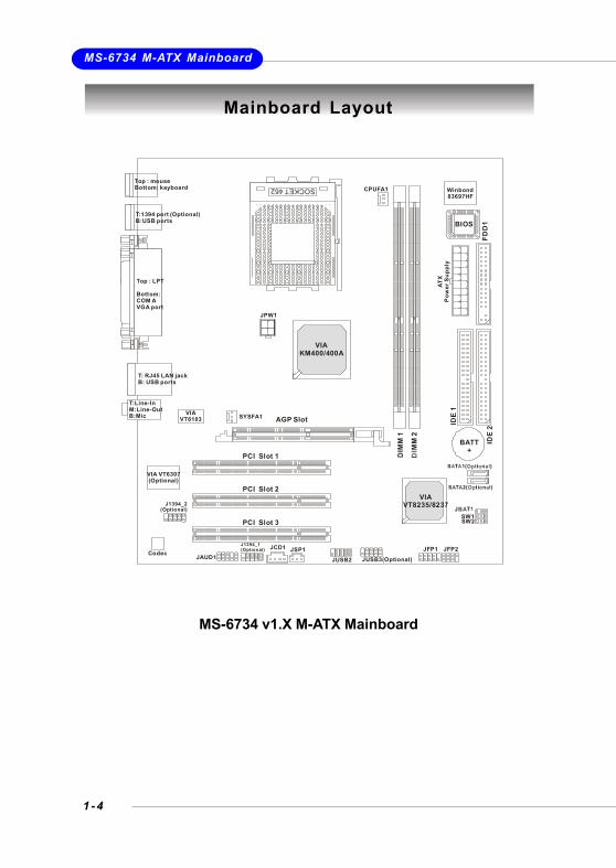
Mainboard Layout
MS-6734 v1.X M-ATX Mainboard
SOCKET 462
AGP Slot
Top : mouse Bottom: keyboard
T:1394 port (Optional)B:USB ports
T: RJ45 LAN jackB: USB ports
JCD1
VIA VT6307(Optional)
VIAVT6103
JSP1
J1394_2(Optional)
J1394_1(Optional)Codec JAUD1
BATT+
BIOS
Winbond83697HF
VIAVT8235/8237
VIAKM400/400A
DIM
M 1
IDE
1
IDE
2FD
D1
PCI Slot 1
PCI Slot 2
PCI Slot 3
JUSB2 JUSB3(Optional)
CPUFA1
SYSFA1
JPW1
ATX
Pow
er S
uppl
y
JFP1 JFP2
SW1SW2
Top : LPT
Bottom: COM AVGA port
T:M:B:
Line-InLine-OutMic

2 - 1
Hardware Setup
This chapter tells you how to install the CPU, memory modules, andexpansion cards, as well as how to setup the jumpers on the mainboard.Also, it provides the instructions on connecting the peripheral devices,such as the mouse, keyboard, etc.While doing the installation, be careful in holding the components andfollow the installation procedures.
Hardware Setup
2 - 2
MS-6734 M-ATX Mainboard
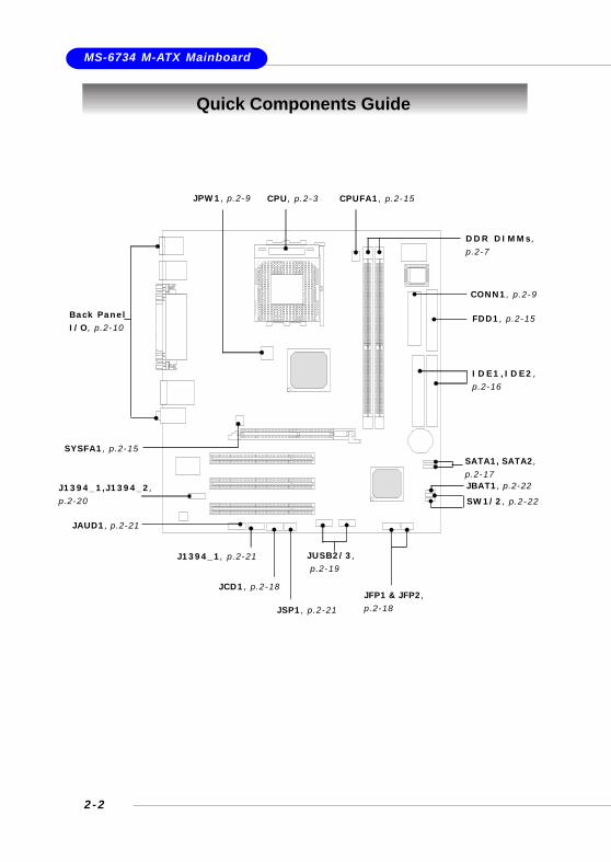
Quick Components Guide
JBAT1, p.2-22
JSP1, p.2-21
DDR DIMMs,p.2-7
CPU, p.2-3 CPUFA1, p.2-15
FDD1, p.2-15
SYSFA1, p.2-15
IDE1,IDE2 ,p.2-16
JFP1 & JFP2,p.2-18
JUSB2/3, p.2-19
JAUD1, p.2-21
JCD1, p.2-18
JPW1, p.2-9
J1394_1,J1394_2,p.2-20 SW1/2, p.2-22
Back PanelI/O, p.2-10
CONN1, p.2-9
J1394_1, p.2-21
SATA1, SATA2,p.2-17

2 - 3
Hardware Setup
Central Processing Unit: CPU
The mainboard supports AMD® Athlon™, Athlon™ XP and Duron™ processors in the462 pin package. The mainboard uses a CPU socket called Socket A for easy CPUinstallation. When you are installing the CPU, make sure the CPU has a heat sinkand a cooling fan attached on the top to prevent overheating. If you do notfind the heat sink and cooling fan, contact your dealer to purchase and install thembefore turning on the computer.
As processor technology pushes to faster speeds and higher performance, thermalmanagement becomes increasingly crucial when building computer systems. Main-taining the proper thermal environment is key to reliable operation. As such, theprocessor must be maintained in the specified thermal requirements.
AMD Athlon™/Duron™/Athlon™ XP processor with a speed of 600MHz and aboverequires a LARGER heatsink and fan. You also need to add thermal grease betweenthe CPU and heatsink to improve heat dissipation. Then, make sure that the CPU andheatsink are securely fastened and in good contact with each other. These areneeded to prevent damaging the processor and ensuring reliable operation. If youwant to get more information on the proper cooling, you can visit AMD’s website forreference.
WARNING! Thermal Issue for CPU
CPU Core Speed Derivation Procedure
If CPU Clock = 100MHzCore/Bus ratio = 14
then CPU core speed = Host Clock x Core/Bus ratio= 100MHz x 14= 1.4 GHz

2 - 4
MS-6734 M-ATX Mainboard
1. Please turn off the power andunplug the power cord beforeinstalling the CPU.
2. Pull the lever sideways awayfrom the socket. Make sure toraise the lever up to a 90-de-gree angle.
3. Look for the gold arrow. The goldarrow should point towards thelever pivot. The CPU can only fitin the correct orientation.
4. If the CPU is correctly installed,the pins should be completelyembedded into the socket andcan not be seen. Please notethat any violation of the correctinstallation procedures maycause permanent damages toyour mainboard.
5. Press the CPU down firmly intothe socket and close the lever.As the CPU is likely to move whilethe lever is being closed, al-ways close the lever with yourfingers pressing tightly on top ofthe CPU to make sure the CPU isproperly and completely embed-ded into the socket.
CPU Installation Procedures for Socket 462
Open Lever
Gold arrow
Gold arrow
90 degree
Correct CPU placement
Incorrect CPU placementGold arrow
Sliding Plate
Close Lever
Press downthe CPU
X
O

2 - 5
Hardware Setup
Installing AMD Athlon CPU (Socket 462) Cooler Set
Apply some heatsink paste
MSI Reminds You...Please apply some heat sink paste on top of your CPU to dissipatethe heat more effectively.
The following instructions will guide youthrough the heat s ink ins ta l la t ionprocedures. Please consult your agent forthe proper CPU cooler set.
1. Position your CPU cooler set onto theCPU.
2. Use one end of the clip to hook thelatch of the CPU sliding plate.
3. Hook the other latch to fix the coolingfan set. You may need a screwdrive to press down the other sideof the clip.
4. Connect the fan to the power supplyc o n n e c t o r p r o v i d e d o n y o u rmainboard.

2 - 6
MS-6734 M-ATX Mainboard
CPU Clock Frequency Selection through BIOSThe hardware configuration for CPU clock frequency of the motherboard is set to100MHz by default. Therefore, to make a 133MHz CPU run at 133MHz when it isinstalled on the board, you have to adjust the CPU clock frequency in the BIOS setuputility.To set the clock frequency for the installed CPU, refer to Frequency/Voltage Controlin Chapter 3. BIOS Setup.
MSI Reminds You...OverheatingOverheating will seriously damage the CPU and system, always makesure the cooling fan can work properly to protect the CPU fromoverheating.
Replacing the CPUWhile replacing the CPU, always turn off the ATX power supply orunplug the power supply’s power cord from grounded outlet first toensure the safety of CPU.
OverclockingThis motherboard is designed to support overclocking. However,please make sure your components are able to tolerate such abnor-mal setting, while doing overclocking. Any attempt to operate be-yond product specifications is not recommended. We do not guar-antee the damages or risks caused by inadequate operationor beyond product specifications.
2 - 7
Hardware Setup
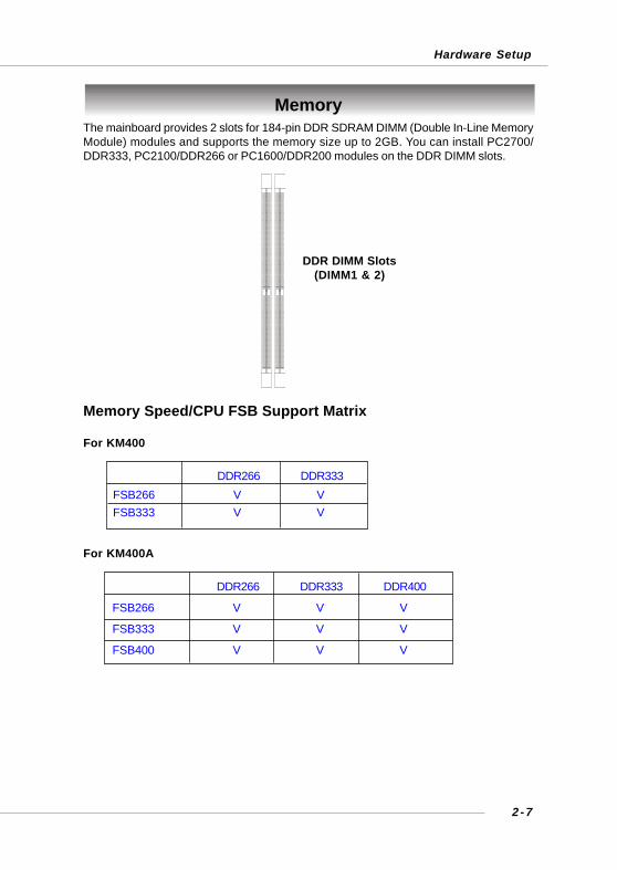
MemoryThe mainboard provides 2 slots for 184-pin DDR SDRAM DIMM (Double In-Line MemoryModule) modules and supports the memory size up to 2GB. You can install PC2700/DDR333, PC2100/DDR266 or PC1600/DDR200 modules on the DDR DIMM slots.
DDR DIMM Slots(DIMM1 & 2)
Memory Speed/CPU FSB Support Matrix
For KM400
For KM400A
DDR266 DDR333FSB266 V VFSB333 V V
DDR266 DDR333 DDR400
FSB266 V V V
FSB333 V V V
FSB400 V V V
2 - 8
MS-6734 M-ATX Mainboard
DIMM Module CombinationInstall at least one DIMM module on the slots. You can install either single- or double-sided modules in any order to meet your own needs.Memory modules can be installed in any combination as follows:
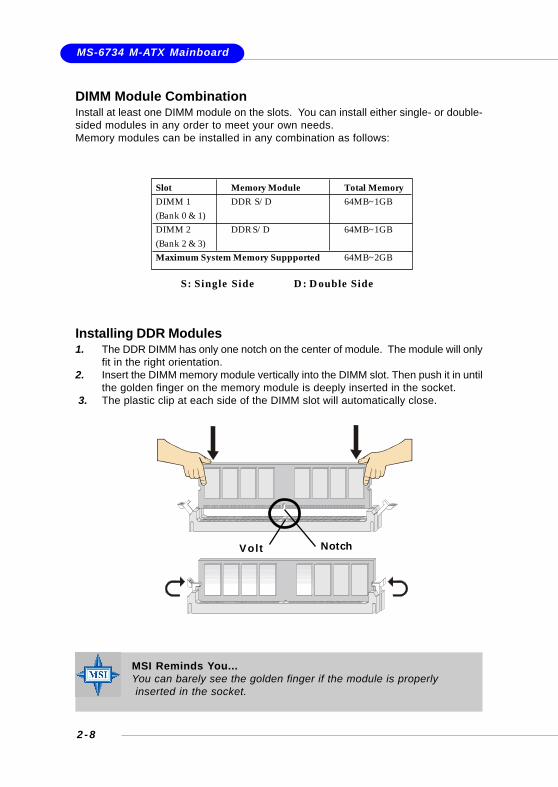
Installing DDR Modules1. The DDR DIMM has only one notch on the center of module. The module will only
fit in the right orientation.2. Insert the DIMM memory module vertically into the DIMM slot. Then push it in until
the golden finger on the memory module is deeply inserted in the socket. 3. The plastic clip at each side of the DIMM slot will automatically close.
MSI Reminds You...You can barely see the golden finger if the module is properly inserted in the socket.
Volt Notch
S: Single Side D: Double Side
Slot Memory Module Total MemoryDIMM 1 DDR S/D 64MB~1GB(Bank 0 & 1)DIMM 2 DDR S/D 64MB~1GB(Bank 2 & 3)Maximum System Memory Suppported 64MB~2GB

2 - 9
Hardware Setup
Power Supply
The mainboard supports ATX power supply for the power system. Before insertingthe power supply connector, always make sure that all components are installedproperly to ensure that no damage will be caused.
ATX 20-Pin Power Connector: CONN1This connector allows you to connect to an ATX power supply. To connect to the ATXpower supply, make sure the plug of the power supply is inserted in the properorientation and the pins are aligned. Then push down the power supply firmly into theconnector.
PIN SIGNAL
11 3.3V12 -12V13 GND14 PS_ON15 GND16 GND17 GND18 -5V19 5V20 5V
PIN SIGNAL
1 3.3V2 3.3V3 GND4 5V5 GND6 5V7 GND8 PW_OK9 5V_SB10 12V
CONN1 Pin Definition
CONN110
1
20
11
JPW1
1
34
2
ATX 12V Power Connector: JPW1This 12V power connector is used to provide power to the CPU.
PIN SIGNAL
1 GND2 GND3 12V4 12V
JPW1 Pin Definition

2-10
MS-6734 M-ATX Mainboard
The back panel provides the following connectors:
Back Panel
Mouse ConnectorThe mainboard provides a standard PS/2® mouse mini DIN connector for attaching aPS/2® mouse. You can plug a PS/2® mouse directly into this connector. The connec-tor location and pin assignments are as follows:
PIN SIGNAL DESCRIPTION
1 Mouse DATA Mouse DATA2 NC No connection3 GND Ground4 VCC +5V5 Mouse Clock Mouse clock6 NC No connection
Pin Definition
PS/2 Mouse (6-pin Female)2 1
34
56
Mouse
Keyboard USB
Parallel
COM VGA
L-out
L-in
MIC
LAN(Optional)
USB
IEEE1394(Optional)

2-11
Hardware Setup
Keyboard ConnectorThe mainboard provides a standard PS/2® keyboard mini DIN connector for attachinga PS/2® keyboard. You can plug a PS/2® keyboard directly into this connector.
PIN SIGNAL DESCRIPTION
1 Keyboard DATA Keyboard DATA2 NC No connection3 GND Ground4 VCC +5V5 Keyboard Clock Keyboard clock6 NC No connection
Pin Definition
PS/2 Keyboard (6-pin Female)2 1
34
56
USB ConnectorsThe mainboard provides a UHCI (Universal Host Controller Interface) Universal SerialBus root for attaching USB devices such as keyboard, mouse or other USB-compat-ible devices. You can plug the USB device directly into the connector.
PIN SIGNAL DESCRIPTION1 VCC +5V2 -Data 0 Negative Data Channel 03 +Data0 Positive Data Channel 04 GND Ground5 VCC +5V6 -Data 1 Negative Data Channel 17 +Data 1 Positive Data Channel 18 GND Ground
USB Port Description
USB Ports
1 2 3 4
5 6 7 8

2-12
MS-6734 M-ATX Mainboard
IEEE1394 Port (Optional)The back panel provides one standard IEEE 1394 port. The standard IEEE1394 portconnects to IEEE1394 devices without external power. The IEEE1394 high-speedserial bus complements USB by providing enhanced PC connectivity for a wide rangeof devices, including consumer electronics audio/video (A/V) appliances, storageperipherals, other PCs, and portable devices.
IEEE1394 Port
Serial Port Connector: COM 1The mainboard offers one 9-pin male DIN connector as serial port COM 1. The port isa 16550A high speed communication port that sends/receives 16 bytes FIFOs. Youcan attach a serial mouse or other serial devices directly to the connector.
PIN SIGNAL DESCRIPTION
1 DCD Data Carry Detect2 SIN Serial In or Receive Data3 SOUT Serial Out or Transmit Data4 DTR Data Terminal Ready)5 GND Ground6 DSR Data Set Ready7 RTS Request To Send8 CTS Clear To Send9 RI Ring Indicate
Pin Definition
9-Pin Male DIN Connector
1 2 3 4 5
6 7 8 9
VGA ConnectorThe mainboard provides a DB 15-pin female connector to connect a VGA monitor.
VGA Connector(DB 15-pin)
15
1115
Pin Signal Description Pin Signal Description 1 RED 2 GREEN 3 BLUE 4 N/C 5 GND 6 GND 7 GND 8 GND 9 +5V 10 GND 11 N/C 12 SDA 13 Horizontal Sync 14 Vertical Sync 15 SCL

2-13
Hardware Setup
RJ-45 LAN Jack (Optional)The mainboard provides a RJ-45 connector that allows your computer to be con-nected to a network environment.
LAN Jack (RJ-45)
ActivityIndicators
Pin Signal Description 1 TDP Transmit differential pair 2 TDN Transmit differential pair 3 RDP Receive differential pair 4 NC Not used 5 NC Not used 6 RDN Receive differential pair 7 NC Not used 8 NC Not used
Audio Port ConnectorsLine Out is a connector for Speakers or Headphones. Line In is used for externalCD player, Tape player, or other audio devices. Mic is a connector for microphones.
1/8” Stereo Audio Connectors
Mic In
Line Out
Line In

2-14
MS-6734 M-ATX Mainboard
Parallel Port Connector: LPT1The mainboard provides a 25-pin female centronic connector as LPT. A parallel portis a standard printer port that supports Enhanced Parallel Port (EPP) and ExtendedCapabilities Parallel Port (ECP) mode.
13 1
1425
PIN SIGNAL DESCRIPTION1 STROBE Strobe2 DATA0 Data03 DATA1 Data14 DATA2 Data25 DATA3 Data36 DATA4 Data47 DATA5 Data58 DATA6 Data69 DATA7 Data710 ACK# Acknowledge11 BUSY Busy12 PE Paper End13 SELECT Select14 AUTO FEED# Automatic Feed15 ERR# Error16 INIT# Initialize Printer17 SLIN# Select In18 GND Ground19 GND Ground20 GND Ground21 GND Ground22 GND Ground23 GND Ground24 GND Ground25 GND Ground
Pin Definition

2-15
Hardware Setup
The mainboard provides connectors to connect to FDD, IDE HDD, case, LAN, USBPorts and CPU/System FAN.
Floppy Disk Drive Connector: FDD1The mainboard provides a standard floppy disk drive connector that supports 360K,720K, 1.2M, 1.44M and 2.88M floppy disk types.
Connectors
FDD1
Fan Power Connectors: CPUFA1/SYSFA1The CPUFA1 (processor fan) and SYSFA1 (system fan) support system cooling fanwith +12V. It supports three-pin head connector. When connecting the wire to theconnectors, always take note that the red wire is the positive and should be con-nected to the +12V, the black wire is Ground and should be connected to GND. If themainboard has a System Hardware Monitor chipset on-board, you must use a spe-cially designed fan with speed sensor to take advantage of the CPU fan control.
MSI Reminds You...1. Always consult the vendors for proper CPU cooling fan.2. CPUFA1 supports the fan control. You can install the PC Alert utility
that will automatically control the CPU fan speed according to theactual CPU temperature.
CPUFA1SENSOR+12VGND
SYSFA1SENSOR+12VGND

2-16
MS-6734 M-ATX Mainboard
Hard Disk Connectors: IDE1 & IDE2The mainboard has a 32-bit Enhanced PCI IDE and Ultra DMA 33/66/100/133 controllerthat provides PIO mode 0~4, Bus Master, and Ultra DMA 33/66/100/133 function. Youcan connect up to four hard disk drives, CD-ROM, 120MB Floppy (reserved for futureBIOS) and other devices.
IDE1 (Primary IDE Connector)The first hard drive should always be connected to IDE1. IDE1 can connect aMaster and a Slave drive. You must configure second hard drive to Slavemode by setting the jumper accordingly.
IDE2 (Secondary IDE Connector)IDE2 can also connect a Master and a Slave drive.
IDE1 IDE2
MSI Reminds You...If you install two hard disks on cable, you must configure the seconddrive to Slave mode by setting its jumper. Refer to the hard diskdocumentation supplied by hard disk vendors for jumper settinginstructions.
2-17
Hardware Setup
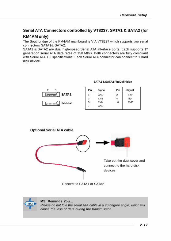
Serial ATA Connectors controlled by VT8237: SATA1 & SATA2 (forKM4AM only)The Southbridge of the KM4AM mainboard is VIA VT8237 which supports two serialconnectors SATA1& SATA2.SATA1 & SATA2 are dual high-speed Serial ATA interface ports. Each supports 1st
generation serial ATA data rates of 150 MB/s. Both connectors are fully compliantwith Serial ATA 1.0 specifications. Each Serial ATA connector can connect to 1 harddisk device.
7 1
SATA2
SATA1
MSI Reminds You...Please do not fold the serial ATA cable in a 90-degree angle, which willcause the loss of data during the transmission.
SATA1 & SATA2 Pin Definition
Pin Signal Pin Signal
1 GND 2 TXP3 TXN 4 ND5 RXN 6 RXP7 GND
Optional Serial ATA cable
Connect to SATA1 or SATA2
Take out the dust cover andconnect to the hard diskdevices

2-18
MS-6734 M-ATX Mainboard
Front Panel Connectors: JFP1 & JFP2The mainboard provides two front panel connectors for electrical connection to thefront panel switches and LEDs. JFP1 is compliant with Intel® Front Panel I/O Connec-tivity Design Guide.
PIN SIGNAL DESCRIPTION
1 HD_LED_P Hard disk LED pull-up2 FP PWR/SLP MSG LED pull-up3 HD_LED_N Hard disk active LED4 FP PWR/SLP MSG LED pull-up5 RST_SW_N Reset Switch low reference pull-down to GND6 PWR_SW_P Power Switch high reference pull-up7 RST_SW_P Reset Switch high reference pull-up8 PWR_SW_N Power Switch low reference pull-down to GND9 RSVD_DNU Reserved. Do not use.
JFP1 Pin Definition
PIN SIGNAL PIN SIGNAL
1 GND 2 SPK-3 SLED 4 BUZ+5 PLED 6 BUZ-7 NC 8 SPK+
JFP2 Pin Definition
JFP1 12
910
HDDLED
ResetSwitch
PowerLED
PowerSwitch
JFP2
PowerLED
Speaker
12
78
CD-In Connector: JCD1The connector is for CD-ROM audio connector.
JCD1
GND
R L

2-19
Hardware Setup
Front USB Connectors: JUSB2 & JUSB3 (JUSB3 is optional)The mainboard provides one standard USB 2.0 pin headers JUSB2 and one optionalstandard JUSB3. USB 2.0 technology increases data transfer rate up to a maximumthroughput of 480Mbps, which is 40 times faster than USB 1.1, and is ideal forconnecting high-speed USB interface peripherals such as USB HDD, digital cameras,MP3 players, printers, modems and the like.
PIN SIGNAL PIN SIGNAL
1 VCC 2 VCC
3 USB0- 4 USB1-
5 USB0+ 6 USB1+
7 GND 8 GND
9 Key 10 USBOC
Pin Definition
JUSB2/JUSB3 (Optional)
9 10
1 2
Connected to JUSB2or JUSB3
USB 2.0 Bracket(Optional)
2-20
MS-6734 M-ATX Mainboard
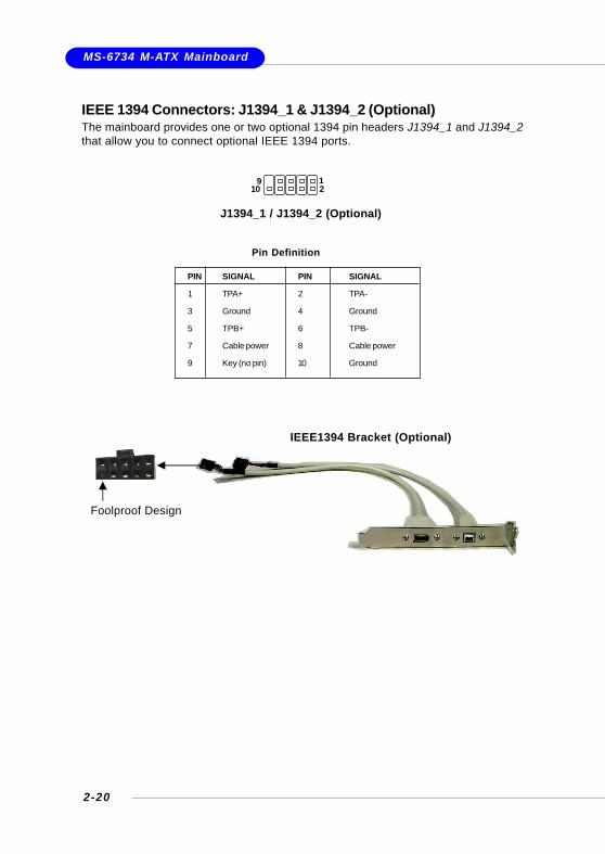
IEEE 1394 Connectors: J1394_1 & J1394_2 (Optional)The mainboard provides one or two optional 1394 pin headers J1394_1 and J1394_2that allow you to connect optional IEEE 1394 ports.
Pin Definition
PIN SIGNAL PIN SIGNAL
1 TPA+ 2 TPA-
3 Ground 4 Ground
5 TPB+ 6 TPB-
7 Cable power 8 Cable power
9 Key (no pin) 10 Ground
J1394_1 / J1394_2 (Optional)
1 9 2 10
IEEE1394 Bracket (Optional)
Foolproof Design

2-21
Hardware Setup
Connected to JSP1
SPDIF Bracket (optional)
Front Panel Audio Connector: JAUD1The JAUD1 front panel audio connector allows you to connect to the front panelaudio and is compliant with Intel® Front Panel I/O Connectivity Design Guide.
JAUD1
1 2 10
9
MSI Reminds You...If you don’t want to connect to the front audio header, pins5 & 6, 9 & 10 have to be jumpered in order to have signaloutput directed to the rear audio ports. Otherwise, theLine-Out connector on the back panel will not function.
5
6 10
9
JSP1
VCC
SPDIF
GND
SPDIF-Out Connector: JSP1This connector is used to connect SPDIF (Sony & Philips Digital Interconnect Format)interface for digital audio transmission.
PIN SIGNAL DESCRIPTION
1 AUD_MIC Front panel microphone input signal2 AUD_GND Ground used by analog audio circuits3 AUD_MIC_BIAS Microphone power4 AUD_VCC Filtered +5V used by analog audio circuits5 AUD_FPOUT_R Right channel audio signal to front panel6 AUD_RET_R Right channel audio signal return from front panel7 HP_ON Reserved for future use to control headphone amplifier8 KEY No pin9 AUD_FPOUT_L Left channel audio signal to front panel10 AUD_RET_L Left channel audio signal return from front panel
JAUD1 Pin Definition

2-22
MS-6734 M-ATX Mainboard
CPU Frequency Jumpers: SW1 & SW2These two jumpers provide 100MHz, 133MHz, 166MHz, and 200MHz Front Side Busfrequency selection for overclocking purpose.
SW1 & SW2
13
The motherboard provides the following jumpers for you to set the computer’s function.This section will explain how to change your motherboard’s function through the useof jumpers.
Clear CMOS Jumper: JBAT1There is a CMOS RAM on board that has a power supply from external battery tokeep the data of system configuration. With the CMOS RAM, the system can auto-matically boot OS every time it is turned on. If you want to clear the system configuration,se the JBAT1 (Clear CMOS Jumper ) to clear data. Follow the instructions below toclear the data:
Jumpers
JBAT1
13
Clear Data
13
Keep Data
13
MSI Reminds You...You can clear CMOS by shorting 2-3 pin while the system is off. Thenreturn to 1-2 pin position. Avoid clearing the CMOS while the systemis on; it will damage the mainboard.
FSB = 100MHz
FSB = 133MHz
FSB = 166MHz
FSB = 200MHz(for KM4AM only)
SW113
SW213
13
SW1 SW213
SW1 SW2
13 13
13
SW1 SW213

2-23
Hardware Setup
Slots
AGP (Accelerated Graphics Port) SlotThe AGP slot allows you to insert the AGP graphics card. AGP is an interfacespecification designed for the throughput demands of 3D graphics. It introduces a66MHz, 32-bit channel for the graphics controller to directly access main memory.The mainboard supports 4x/8x 1.5V AGP card.
The motherboard provides one AGP slot and three 32-bit PCI bus slots.
AGP Slot
PCI Slots
PCI (Peripheral Component Interconnect) SlotsThe PCI slots allow you to insert the expansion cards to meet your needs. Whenadding or removing expansion cards, make sure that you unplug the power supplyfirst. Meanwhile, read the documentation for the expansion card to make any neces-sary hardware or software settings for the expansion card, such as jumpers,switches or BIOS configuration.
PCI Interrupt Request RoutingThe IRQ, acronym of interrupt request line and pronounced I-R-Q, are hardware linesover which devices can send interrupt signals to the microprocessor.The PCI IRQ pins are typically connected to the PCI bus INT A# ~ INT D# pins asfollows:
Order 1 Order 2 Order 3 Order 4
PCI Slot 1 INT A# INT B# INT C# INT D#
PCI Slot 2 INT B# INT C# INT D# INT A#
PCI Slot 3 INT C# INT D# INT A# INT B#
3 - 1
BIOS Setup
Chapter 3. BIOS Setup
This chapter provides information on the BIOS Setup program and allowsyou to configure the system for optimum use.You may need to run the Setup program when:
An error message appears on the screen during the system bootingup, and requests you to run SETUP.
You want to change the default settings for customized features.
BIOS Setup
MSI Reminds You...1. The items under each BIOS category described in this chapter are
under continuous update for better system performance.Therefore, the description may be slightly different from the latestBIOS and should be held for reference only.
2. While booting up, the BIOS version is shown in the 1st line ap-pearing after the memory counting. It is usually in the format:example: W7005MS V2.0 091096
where:1st digit refers to BIOS maker as A=AMI(R); W=AWARD(R)2nd - 5th digit refers to the model number.6th - 7th digit refers to the customer, MS=all standard customers.V2.0 refers to the BIOS version.091096 refers to the date this BIOS is released.

3 - 2
MS-6734 M-ATX Mainboard
Entering SetupPower on the computer and the system will start POST (Power On Self Test) process.When the message below appears on the screen, press <DEL> key to enter Setup.
Press DEL to enter SETUP
If the message disappears before you respond and you still wish to enter Setup,restart the system by turning it OFF and On or pressing the RESET button. You mayalso restart the system by simultaneously pressing <Ctrl>, <Alt>, and <Delete> keys.
Control Keys
Getting HelpAfter entering the Setup menu, the first menu you will see is the Main Menu.
Main MenuThe main menu lists the setup functions you can make changes to. You can use thecontrol keys ( ↑↓ ) to select the item. The on-line description of the highlighted setupfunction is displayed at the bottom of the screen.
Sub-MenuIf you find a right pointer symbol (as shown in theright view) appears to the left of certain fields thatmeans a sub-menu containing additional options canbe launched from this field. You can use control keys( ↑↓ ) to highlight the field and press <Enter> to call upthe sub-menu. Then you can use the control keys toenter values and move from field to field within a sub-menu. If you want to return tothe main menu, just press <Esc >.
General Help <F1>The BIOS setup program provides a General Help screen. You can call up this screenfrom any menu by simply pressing <F1>. The Help screen lists the appropriate keysto use and the possible selections for the highlighted item. Press <Esc> to exit theHelp screen.
<↑ > Move to the previous item<↓ > Move to the next item<←> Move to the item in the left hand<→> Move to the item in the right hand<Enter> Select the item<Esc> Jumps to the Exit menu or returns to the main menu from a submenu<+/PU> Increase the numeric value or make changes<-/PD> Decrease the numeric value or make changes<F1> General help, only for Status Page Setup Menu and Option Page Setup Menu

3 - 3
BIOS Setup
The Main Menu
Standard CMOS FeaturesUse this menu for basic system configurations, such as time, date etc.
Advanced BIOS FeaturesUse this menu to setup the items of special enhanced features.
Advanced Chipset FeaturesUse this menu to change the values in the chipset registers and optimize your system’sperformance.
Integrated PeripheralsUse this menu to specify your settings for integrated peripherals.
Power Management SetupUse this menu to specify your settings for power management.
PnP/PCI ConfigurationsThis entry appears if your system supports PnP/PCI.
PC Health StatusThis entry shows your PC health status.
Once you enter Phoenix-Award® BIOS CMOS Setup Utility, the Main Menu (Figure 1)will appear on the screen. The Main Menu allows you to select from twelve setupfunctions and two exit choices. Use arrow keys to select among the items and press<Enter> to accept or enter the sub-menu.

3 - 4
MS-6734 M-ATX Mainboard
Frequency/Voltage ControlUse this menu to specify your settings for frequency/voltage control.
Load Fail-Safe DefaultsUse this menu to load the BIOS values for the best system performance, but thesystem stability may be affected.
Load Optimized DefaultsUse this menu to load factory default settings into the BIOS for stable system perfor-mance operations.
Set Supervisor PasswordUse this menu to set Supervisor Password.
Set User PasswordUse this menu to set User Password.
Save & Exit SetupSave changes to CMOS and exit setup.
Exit Without SavingAbandon all changes and exit setup.

3 - 5
BIOS Setup
Standard CMOS Features
DateThis allows you to set the system to the date that you want (usually the current date). The format is <day><month> <date> <year>.
day Day of the week, from Sun to Sat, determined byBIOS. Read-only.
month The month from Jan. through Dec.date The date from 1 to 31 can be keyed by numeric
function keys.year The year can be adjusted by users.
TimeThis allows you to set the system time that you want (usually the current time). Thetime format is <hour> <minute> <second>.
IDE Primary/Secondary Master/SlavePress PgUp/<+> or PgDn/<-> to select Manual, None or Auto type. Note that thespecifications of your drive must match with the drive table. The hard disk will notwork properly if you enter improper information for this category. If your hard diskdrive type is not matched or listed, you can use Manual to define your own drive typemanually.
The items in Standard CMOS Features Menu are divided into 11 categories. Eachcategory includes no, one or more than one setup items. Use the arrow keys tohighlight the item and then use the <PgUp> or <PgDn> keys to select the value youwant in each item.
3 - 6
MS-6734 M-ATX Mainboard
If you select Manual, related information is asked to be entered to the following items.Enter the information directly from the keyboard. This information should be providedin the documentation from your hard disk vendor or the system manufacturer.
Access Mode The settings are CHS, LBA, Large, Auto.Capacity The formatted size of the storage device.Cylinder Number of cylinders.Head Number of heads.Precomp Write precompensation.Landing Zone Cylinder location of the landing zone.Sector Number of sectors.
Drive A:/B:This item allows you to set the type of floppy drives installed. Available options:None, 360K 5.25, 1.2 MB 5.25, 720 KB 3.5, 1.44 MB 3.5 and 2.88 MB 3.5.
VideoThe setting controls the type of video adapter used for the primary monitor of thesystem. Available options: EGA/VGA , CGA 40, CGA 80, MONO.
Halt OnThe setting determines whether the system will stop if an error is detected at boot.Available options are:
All Errors The system stops when any error is detected.No Errors The system doesn’t stop for any detected error.All, But Keyboard The system doesn’t stop for a keyboard error.All, But Diskette The system doesn’t stop for a disk error.All, But Disk/Key The system doesn’t stop for either a disk or a key-
board error.
Base/Extended/Total MemoryThe three items show the memory status of your system (read only).

3 - 7
BIOS Setup
Advanced BIOS Features
Quick BootSetting the item to Enabled allows the system to boot within 5 seconds since it willskip some check items. Available options: Enabled, Disabled.
Anti-Virus ProtectionThe item is to set the Virus Warning feature for IDE Hard Disk boot sector protection.If the function is enabled and any attempt to write data into this area is made, BIOSwill display a warning message on screen and beep. Settings: Disabled and Enabled.
Boot SequencePress <Enter> to enter the sub-menu screen.
1st/2nd/3rd Boot DeviceThe items allow you to set the sequence of boot devices where BIOS attempts toload the disk operating system.
Boot Other DeviceSetting the option to Enabled allows the system to try to boot from other devices ifthe system fails to boot from the 1st/2nd/3rd boot device. Settings: Enabled, Disabled.
MSI Reminds You...Available settings for “1st/2nd/3rd Boot Device” vary depending on thebootable devices you have installed. For example, if you did not installa floppy drive, the setting “Floppy” does not show up.

3 - 8
MS-6734 M-ATX Mainboard
CPU Internal CacheThe item allows you to turn on or off CPU’s internal (L1) cache. Settings: Enabledand Disabled.
CPU L2 Cache ECC CheckingThis setting allows you to enable or disable the ECC (Error-Correcting Code)feature for error detection and correction when data passes through L2 (external)cache memory. Setting options: Enabled, Disabled.
Swap FloppySetting to Enabled will swap floppy drives A: and B:.
Seek FloppySetting to Enabled will make BIOS seek floppy drive A: before booting the system.Settings: Disabled, Enabled.
Boot Up NumLock StatusThis setting is to set the Num Lock status when the system is powered on.Setting to On will turn on the Num Lock key when the system is powered on.Setting to Off will allow users to use the arrow keys on the numeric keypad.Setting options: On, Off.
Typematic Rate SettingWhen Disabled, the following two items (Typematic Rate and Typematic Delay)are irrelevant. Keystrokes repeat at a rate determined by the keyboard controllerin your system. When Enabled, you can select a typematic rate and typematicdelay.
Typematic Delay (Msec)This item allows you to select the delay between when the key was first pressedand when the acceleration begins. Settings: 250, 500, 750 and 1000.
Typematic Rate (Chars/Sec)After Typematic Rate Setting is enabled, this item allows you to set the rate(characters/second) at which the keys are accelerated. Settings: 6, 8, 10, 12, 15,20, 24 and 30.
Security OptionThis specifies the type of BIOS password protection that is implemented. Settingsare described below:
Option Description
Setup The password prompt appears only when end users try to runSetup.
System A password prompt appears every time when the computer ispowered on or when end users try to run Setup.

3 - 9
BIOS Setup
APIC ModeThis field is used to enable or disable the APIC (Advanced Programmable InterruptController). Due to compliance with PC2001 design guide, the system is able to run inAPIC mode. Enabling APIC mode will expand available IRQ resources for the system.Settings: Enabled and Disabled.
MPS Table VersionThis field allows you to select which MPS (Multi-Processor Specification) version tobe used for the operating system. You need to select the MPS version supported byyour operating system. To find out which version to use, consult the vendor of youroperating system. Settings: 1.4, 1.1.
HDD S.M.A.R.T. CapabilityThis allows you to activate the S.M.A.R.T. (Self-Monitoring Analysis & ReportingTechnology) capability for the hard disks. S.M.A.R.T is a utility that monitors your diskstatus to predict hard disk failure. This gives you an opportunity to move data from ahard disk that is going to fail to a safe place before the hard disk becomes offline.Settings: Enabled and Disabled.

3-10
MS-6734 M-ATX Mainboard
Advanced Chipset Features
DRAM Clock/Drive ControlPress <Enter> and the following sub-menu appears.
Current FSB / DRAM / DDR FrequencyThese items show the current FSB/DRAM/DDR frequency. (read only)
DRAM ClockThis item is used to configure the clock frequency of the installed DRAM.Settings: By SPD, 100MHz, 133MHz, 166MHz, 200MHz.
DRAM TimingSelects whether DRAM timing is controlled by the SPD (Serial Presence Detect)EEPROM on the DRAM module. Setting to Auto By SPD enables DRAM timings to bedetermined by BIOS based on the configurations on the SPD. Selecting Manualallows users to configure the DRAM timings manually. Options: Auto By SPD, Manual,Turbo, Ultra.
MSI Reminds You...Change these settings only if you are familiar with the chipset.

3-11
BIOS Setup
DRAM CAS LatencyWhen synchronous DRAM is installed, the number of clock cycles of CAS latencydepends on the DRAM timing. The settings are: 1.5, 2, 2.5, 3.
Bank InterleaveThis field selects 2-bank or 4-bank interleave for the installed SDRAM. Disable thefunction if 16MB SDRAM is installed. Settings: Disabled, 2 Bank and 4 Bank.
Precharge To Active (Trp)This item controls the number of cycles for Row Address Strobe (RAS) to be allowedto precharge. If insufficient time is allowed for the RAS to accumulate its chargebefore DRAM refresh, refreshing may be incomplete and DRAM may fail to retaindata. This item applies only when synchronous DRAM is installed in the system.Available settings: 2T, 3T.
Trans Non-DDR400/DDR400This controls the timing delay (in clock cycles) before non-DDR400 and DDR400starts a write command after receiving it. Settings: 6T/8T, 7T/10T, 5T/6T, 8T/12T.12T increases the delay time while 5T provides the least timing delay. This option iseffective only if DDR400 is running.
Active to CMD (Trcd)When DRAM is refreshed, both rows and columns are addressed separately. Thissetup item allows you to determine the timing of the transition from RAS (row addressstrobe) to CAS (column address strobe). The less the clock cycles, the faster theDRAM performance. Setting options: 2T, 3T.
DRAM Burst LengthThis setting allows you to set the size of Burst-Length for DRAM. Bursting feature isa technique that DRAM itself predicts the address of the next memory location to beaccessed after the first address is accessed. To use the feature, you need to definethe burst length, which is the actual length of burst plus the starting address andallows internal address counter to properly generate the next memory location. Thebigger the size, the faster the DRAM performance. Settings: 4, 8.
DRAM Command RateThis setting controls the SDRAM command rate. Selecting 1T allows SDRAM signalcontroller to run at 1T (T=clock cycles) rate. Selecting 2T makes SDRAM signalcontroller run at 2T rate. 1T is faster than 2T. Setting options: 1T Command, 2TCommand.
DDR VoltageAdjusting the DDR voltage can increase the DDR speed. Any changes made to thissetting may cause a stability issue, so changing the DDR voltage for long-termpurpose is NOT recommended.

3-12
MS-6734 M-ATX Mainboard
AGP & P2P Bridge ControlPress <Enter> and the following sub-menu appears.
AGP Aperture SizeThis setting controls just how much system RAM can be allocated to AGP for videopurposes. The aperture is a portion of the PCI memory address range dedicated tographics memory address space. Host cycles that hit the aperture range are for-warded to the AGP without any translation. The option allows the selection of anaperture size of 4MB, 8MB, 16MB, 32MB, 64MB, 128MB, 256MB, 512MB and 1G.
AGP ModeThe item sets an appropriate mode for the installed AGP card. Setting options: 1x, 2x,4x. Select 4x only if your AGP card supports it.
AGP Driving ControlThis field is used to adjust the AGP driving force. Selecting Manual allows you toselect an AGP driving force in AGP Driving Value. It is strongly suggested to selectAuto to avoid causing any system error.
AGP Driving ValueThis item specifies an AGP driving force.
AGP Fast WriteThis option enables or disables the AGP Fast Write feature. The Fast Write technol-ogy allows the CPU to write directly to the graphics card without passing anythingthrough the system memory and improves the AGP 4X speed. Select Enabled onlywhen your AGP card supports the feature. Options: Disabled, Enabled.
AGP 3.0 Calibration cycleThis setting disables/enables the AGP auto calibration. Setting options: Disabled,Enabled.
VGA Share Memory SizeThe system shares memory to the onboard VGA card. This setting controls theexact memory size shared to the VGA card. Setting options: 16MB, 32MB, 64MB.
CPU Disconnect ControlThe item is to reduce the power consumption of the AMD K7 system. When set toEnabled, the processor is allowed to disconnect the s2k interface when the AMD k7system is in some power saving states. Options: Enabled, Disabled.

3-13
BIOS Setup
Integrated Peripherals
Onboard 1394 ChipThis setting is used to enable/disable the onboard IEEE 1394 controller. Settingoptions: Disabled, Enabled.
VIA OnChip IDE DevicePress <Enter> to enter the sub-menu and the following screen appears:
On-Chip Serial ATAThis setting is used to specify the SATA controller. Settings: Disable, Enabled.
IDE DMA Transfer AccessThis item is used to enable or disable the DMA transfer function of the IDE Hard Drive.The settings are: Enabled, Disabled.
OnChip IDE Channel 0/1The integrated peripheral controller contains an IDE interface with support for twoIDE channels. Choose Enabled to activate each channel separately. Settings: Enabled,Disabled.

3-14
MS-6734 M-ATX Mainboard
Primary/Secondary Master/Slave PIOThe four IDE PIO (Programmed Input/Output) fields let you set a PIO mode (0-4) foreach of the four IDE devices that the onboard IDE interface supports. Modes 0through 4 provide successively increased performance. In Auto mode, the systemautomatically determines the best mode for each device. The settings are: Auto,Mode 0, Mode 1, Mode 2, Mode 3, Mode 4.Primary/Secondary Master/Slave UltraDMAUltra DMA/33 implementation is possible only if your IDE hard drive supports it and theoperating environment includes a DMA driver (Windows 95 OSR2 or a third-party IDEbus master driver). If your hard drive and your system software both support UltraDMA/33, Ultra DMA/66 and Ultra DMA/100 select Auto to enable BIOS support. Thesettings are: Auto, Disabled.
VIA OnChip PCI DevicePress <Enter> to enter the sub-menu and the following screen appears:
AC97 AudioAuto allows the motherboard’s BIOS to detect whether you’re using any audio device.If so, the onboard audio controller will be enabled. If not, the onboard audio controllerwill be disabled. If you want to use different controller cards to connect audioconnectors, set the field to Disabled. Setting options: Disabled, Auto.
OnChip LANSetting to [Auto] allows the BIOS to auto-detect the LAN controller and enable it.Setting options: Auto and Disabled.
Onboard Lan Boot ROMThe item enables or disables the initialization of the onboard LAN Boot ROM duringbootup. Selecting Disabled will speed up the boot process.
OnChip USB ControllerThis setting is used to enable/disable the onboard USB1.1 controller. Setting options:Disabled, Enabled.
OnChip USB2.0 ControllerThis setting is used to enable/disable the onboard USB2.0 controller. Setting options:Disabled, Enabled.
USB Device FunctionThis setting is used to enable/disable the onboard USB device controller. Settingoptions: Disabled, Enabled.

3-15
BIOS Setup
USB Legacy Keyboard/MS SupportSelect Enabled if you need to use a keyboard/mouse in the operating system. Settingoptions: Enabled, Disabled.
Super IO DevicePress <Enter> to enter the sub-menu and the following screen appears:
Onboard FDC ControllerSelect Enabled if your system has a floppy disk controller (FDD) installed on thesystem board and you wish to use it. If you install add-on FDC or the system has nofloppy drive, select Disabled in this field. The settings are: Enabled and Disabled.
Onboard Serial Port 1Select an address and corresponding interrupt for the first serial port. The settingsare: 3F8/IRQ4, 2E8/IRQ3, 3E8/IRQ4, 2F8/IRQ3, Disabled, Auto.directional transmission/reception is allowed. Under Half Duplex mode, onlyasynchronous, bi-directional transmission/reception is allowed.
Onboard Parallel PortThere is a built-in parallel port on the on-board Super I/O chipset that provides Standard,ECP, and EPP features. It has the following options:
Disabled3BC/IRQ7 Line Printer port 0278/IRQ5 Line Printer port 2378/IRQ7 Line Printer port 1
Parallel Port ModeSPP : Standard Parallel PortEPP : Enhanced Parallel PortECP : Extended Capability PortECP + EPP: Extended Capability Port + Enhanced Parallel Port
SPP/EPP/ECP/ECP+EPPTo operate the onboard parallel port as Standard Parallel Port only, choose “SPP.” Tooperate the onboard parallel port in the EPP mode simultaneously, choose “EPP.” Bychoosing “ECP”, the onboard parallel port will operate in ECP mode only. Choosing“ECP + EPP” will allow the onboard parallel port to support both the ECP and EPPmodes simultaneously.
EPP Mode SelectThe onboard parallel port is EPP Spec. compliant, so after the user chooses theonboard parallel port with the EPP function, the following message will be displayed

3-16
MS-6734 M-ATX Mainboard
on the screen: “EPP Mode Select.” At this time either EPP 1.7 spec or EPP 1.9 speccan be chosen.
ECP Mode Use DMAThe ECP mode has to use the DMA channel, so choose the onboard parallel port withthe ECP feature. After selecting it, the following message will appear: “ECP ModeUse DMA.” At this time, the user can choose between DMA channel 3 or 1.
Init Display FirstThis item specifies which VGA card is your primary graphics adapter. Settings: PCISlot and AGP.

3-17
BIOS Setup
Power Management Setup
IPCA FunctionThis item is to activate the ACPI (Advanced Configuration and Power ManagementInterface) function. If your operating system is ACPI-aware, such as Windows 98SE/2000/ME, select Enabled. Available options: Enabled, Disabled.
Sleep StateThis item specifies the power saving modes for ACPI function. If your operatingsystem supports ACPI, such as Windows 98SE, Windows ME and Windows 2000,you can choose to enter the Standby mode in S1(POS) or S3(STR) fashion throughthe setting of this field. Options are:
S1/POS The S1 sleep mode is a low power state. In this state, no sys -tem context is lost (CPU or chipset) and hardware maintains allsystem context.
S3/STR The S3 sleep mode is a lower power state where the informationof system configuration and open applications/files is saved tomain memory that remains powered while most other hardwarecomponents turn off to save energy. The information stored inmemory will be used to restore the system when a “wake up”event occurs.
Power Management OptionThis item is used to select the degree (or type) of power saving and is related tothese modes: Suspend Mode and HDD Power Down. There are three options forpower management:
Min Saving Minimum Power Management. Suspend Mode=1 HourMax Saving Maximum Power Management. Suspend Mode=1 MinUser Define Allows end users to configure each mode separately.
MSI Reminds You...S3-related functions described in this section are available only whenyour BIOS supports S3 sleep mode.

3-18
MS-6734 M-ATX Mainboard
HDD Power DownIf HDD activity is not detected for the length of time specified in this field, the hard diskdrive will be powered down while all other devices remain active. Settings areDisabled and 1 through 15 Min.
Suspend ModeIf system activity is not detected for the length of time specified in this field, alldevices except CPU will be shut off. Settings: Disabled, 1 Min, 2 Min, 4 Min, 8 Min,10 Min, 20 Min, 30 Min, 40 Min, 1 Hour.
MODEM Use IRQThis determines the IRQ in which the MODEM can use. Activity of the selected IRQalways awakens the system. Settings: 3, 4, 5, 7, 9, 10, 11, NA..
Power Button FunctionThis feature sets the function of the power button. Settings are:
Power Off The power button functions as normal power off button.Suspend When you press the power button, the computer enters the
suspend/sleep mode, but if the button is pressed for more thanfour seconds, the computer is turned off.
Run VGABIOS if S3 ResumeWhen ACPI Suspend Mode is set to S3 or S1&S3, users can select the options in thisfield. Selecting [Yes] allows BIOS to call VGABIOS to initialize the VGA card whensystem wakes up (resumes) from S3 sleep state. The system resume time is short-ened when you disable the function, but system will need an AGP driver to initializethe VGA card. Therefore, if the AGP driver of the card does not support the initializa-tion feature, the display may work abnormally or not function after resuming form S3.Options: Auto, Yes, No.
After AC Power LostThis setting specifies whether your system will reboot after a power failure orinterrupt occurs. Available settings are:
Power Off Leaves the computer in the power off state.Power On Leaves the computer in the power on state.Last State Restores the system to the previous status before power
failure or interrupt occurred.
IRQ/Event Activity DetectPress <Enter> and the following sub-menu appears.

3-19
BIOS Setup
PS2KB Wakeup SelectThe item specify how the system will be awakened from power saving mode wheninput signal of the keyboard is detected. If set to Hot Key, it allows you to select theoptions in PS2 KB Wake UP from S3. If set to Password, please press <Enter> to inputpassword and its maximum password is 8 numbers. Options are: Hot Key, Password.
PS2KB Wake Up from S3/S4/S5This setting allows you to enter “Hot Key” (max. 8 numbers) to wake up the systemfrom S3 state. Settings are: Disable, Ctrl+F1~Ctrl+F12, Power, Wake, Any Key.
PS2MS Wake Up from S3/S4/S5This setting allows the activity of the mouse to wake up the system from S3 state.Settings are: Enabled and Disabled.
USB Resume from S3This item allows the activity of the USB device to wake up the system from S3(Suspend to RAM) state. Settings are: Enabled and Disabled.
VGA, LPT & COM, HDD & FDD, PCI MasterThese fields specify whether the system will be awakened from power savingmodes when activity or input signal of the specified hardware peripheral or compo-nent is detected.
Wake Up On PMEWhen set to Enabled, the feature allows your system to be awakened from thepower saving modes through any event on PME (Power Management Event). Set-tings are: Enabled and Disabled.
Resume By AlarmThe field is used to enable or disable the feature of booting up the system on ascheduled time/date.
MSI Reminds You...If you have changed this setting, you must let the system boot up until itenters the operating system, before this function will work.

3-20
MS-6734 M-ATX Mainboard
Date(of Month) AlarmThe field specifies the date for Resume By RTC Alarm. Settings: 0~31.
Time(hh:mm:ss) AlarmThe field specifies the time for Resume By RTC Alarm. Format is <hour><minute><second>.
IRQ Activity MonitoringPress <Enter> and the following sub-menu appears.
Primary INTRSelecting ON will cause the system to wake up from power saving modes if activityis detected from any enabled IRQ channels. Settings: ON, OFF.
IRQ3~IRQ15IRQ3~IRQ15 enable or disable the monitoring of the specified IRQ line. If set to[Enabled], the activity of the specified IRQ line will prevent the system from enteringpower saving modes or awaken it from power saving modes.
MSI Reminds You...IRQ (Interrupt Request) lines are system resources allocated to I/Odevices. When an I/O device needs to gain attention of the operatingsystem, it signals this by causing an IRQ to occur. After receiving thesignal, when the operating system is ready, the system will interruptitself and perform the service required by the I/O device.

3-21
BIOS Setup
PNP/PCI ConfigurationsThis section describes configuring the PCI bus system and PnP (Plug & Play) feature.PCI, or Peripheral Component Interconnect, is a system which allows I/O devices tooperate at speeds nearing the speed the CPU itself uses when communicating withits special components. This section covers some very technical items and it isstrongly recommended that only experienced users should make any changes to thedefault settings.
Clear ESCDNormally, you leave this field Disabled. Select Enabled to reset Extended SystemConfiguration Data (ESCD) when you exit Setup if you have installed a new add-onand the system reconfiguration has caused such a serious conflict that the operatingsystem can not boot. The settings are: Enabled and Disabled.
Resource Controlled ByThe Award Plug and Play BIOS has the capacity to automatically configure all of theboot and Plug and Play compatible devices. However, this capability means abso-lutely nothing unless you are using a Plug and Play operating system such as Win-dows® 95/98. If you set this field to “manual” choose specific resources by going intoeach of the sub menu that follows this field (a sub menu is preceded by a “Ř”). Thesettings are: Auto (ESCD), Manual.
IRQ ResourcesThe items are adjustable only when Resources Controlled By is set to Manual.Press <Enter> and you will enter the sub-menu of the items. IRQ Resources list IRQ3/4/5/7/9/10/11/12/14/15 for users to set each IRQ a type depending on the type ofdevice using the IRQ. Settings are:
PCI Device For Plug & Play compatible devices designed for PCI busarchitecture.
Reserved The IRQ will be reserved for further request.

3-22
MS-6734 M-ATX Mainboard
PCI/VGA Palette SnoopWhen set to Enabled, multiple VGA devices operating on different buses can handledata from the CPU on each set of palette registers on every video device. Bit 5 of thecommand register in the PCI device configuration space is the VGA Palette Snoop bit(0 is disabled). For example, if there are two VGA devices in the computer (one PCIand one ISA) and the:
The setting must be set to Enabled if any ISA bus adapter in the system requires VGApalette snooping.
Assign IRQ for VGA/USBThe items allow you to assign an IRQ line to the VGA card and USB device separately.Options: Enabled, Disabled.
VGA Palette Snoop Bit Setting Action
Disabled Data read or written by the CPU is only directed to the PCIVGA device’s palette registers.
Enabled Data read or written by the CPU is directed to both the PCIVGA device’s palette registers and the ISA VGA device’spalette registers, permitting the palette registers of bothVGA devices to be identical.

3-23
BIOS Setup
PC Health StatusThis section shows the status of your CPU, fan, overall system status, etc. Monitorfunction is available only if there is hardware monitoring mechanism onboard.
CPU Warning TemperatureThis item is used to specify a thermal limit for CPU. If CPU temperature reaches thespecified limit, the system will issue a warning which allows you to prevent the CPUoverheat problem. Settings: Disabled, 50oC/122oF, 53oC/127oF, 56oC/133oF, 60oC/140oF, 63oC/145oF, 66oC/151oF and 70oC/158oF.
System/CPU Temperature, System/CPU Fan Speed, Vcore, +3.3V, +5V, +12V,-12V, -5V, VBAT(V), 5VSB(V)These items display the current status of all of the monitored hardware devices/components such as CPU voltages, temperatures and all fans’ speeds.
Shutdown TemperatureWhen the processor reaches the preset temperature, the ACPI-aware system will beshut down. Settings: Disabled, 60oC/140oF, 65oC/149oF, 70oC/158oF, 75oC/167oF.
3-24
MS-6734 M-ATX Mainboard
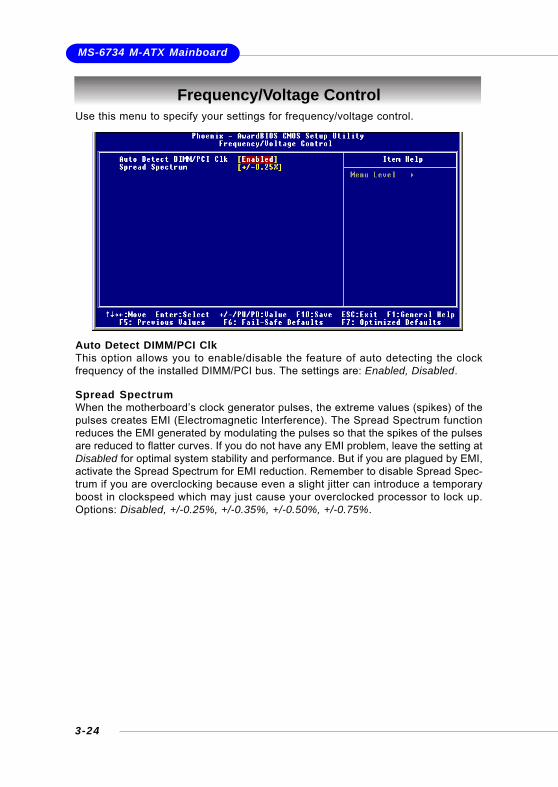
Use this menu to specify your settings for frequency/voltage control.
Frequency/Voltage Control
Auto Detect DIMM/PCI ClkThis option allows you to enable/disable the feature of auto detecting the clockfrequency of the installed DIMM/PCI bus. The settings are: Enabled, Disabled.
Spread SpectrumWhen the motherboard’s clock generator pulses, the extreme values (spikes) of thepulses creates EMI (Electromagnetic Interference). The Spread Spectrum functionreduces the EMI generated by modulating the pulses so that the spikes of the pulsesare reduced to flatter curves. If you do not have any EMI problem, leave the setting atDisabled for optimal system stability and performance. But if you are plagued by EMI,activate the Spread Spectrum for EMI reduction. Remember to disable Spread Spec-trum if you are overclocking because even a slight jitter can introduce a temporaryboost in clockspeed which may just cause your overclocked processor to lock up.Options: Disabled, +/-0.25%, +/-0.35%, +/-0.50%, +/-0.75%.

3-25
BIOS Setup
Load Fail-Safe/Optimized DefaultsThe two options on the main menu allow users to restore all of the BIOS settings tothe default Fail-Safe or Optimized values. The Optimized Defaults are the defaultvalues set by the mainboard manufacturer specifically for optimal performance of themainboard. The Fail-Safe Defaults are the default values set by the BIOS vendor forstable system performance.
When you select Load Fail-Safe Defaults, a message as below appears:
Pressing Y loads the BIOS default values for the most stable, minimal systemperformance.
When you select Load Optimized Defaults, a message as below appears:
Pressing Y loads the default factory settings for optimal system performance.

3-26
MS-6734 M-ATX Mainboard
When you select this function, a message as below will appear on the screen:
Type the password, up to eight characters in length, and press <Enter>. The pass-word typed now will replace any previously set password from CMOS memory. Youwill be prompted to confirm the password. Retype the password and press <Enter>.You may also press <Esc> to abort the selection and not enter a password.
To clear a set password, just press <Enter> when you are prompted to enter thepassword. A message will show up confirming the password will be disabled. Oncethe password is disabled, the system will boot and you can enter Setup withoutentering any password.
When a password has been set, you will be prompted to enter it every time you tryto enter Setup. This prevents an unauthorized person from changing any part of yoursystem configuration.
Additionally, when a password is enabled, you can also have BIOS to request apassword each time the system is booted. This would prevent unauthorized use ofyour computer. The setting to determine when the password prompt is required is theSecurity Option of the Advanced BIOS Feature menu. If the Security Option is set toSystem, the password is required both at boot and at entry to Setup. If set to Setup,password prompt only occurs when you try to enter Setup.
Set Supervisor/User Password
MSI Reminds You...About Supervisor Password & User Password:Supervisor password: Can enter and change the settings of the
setup menu.User password: Can only enter but do not have the right to
change the settings of the setup menu.

VIA VT8237 Serial ATA RAID Introduction
4 - 1
Chapter 4. VIA VT8237 SerialATA RAID Introduction
Appendix. Using 4- or 6-ChannelAudio Function
The Southbridge VT8237 provides a hybrid solution that combines twoindependent SATA ports for support of up to two Serial ATA (Serial ATA RAID)drives.
Serial ATA (SATA) is the latest generation of the ATA interface. SATA harddrives deliver blistering transfer speeds of up to 150MB/sec. Serial ATA uses long,thin cables, making it easier to connect your drive and improving the airflow insideyour PC.
The key features of VT8237 SATA RAID are:1. Support two SATA + two PATA hard disk drives.2. Only SATA supports RAID.3. Supports ATA 133 high performance hard disk drive.4. Dual independent ATA channels and maximum connection of four
hard disk drives allowed.5. Supports Ultra DMA mode 6/5/4/3/2/1/0, DMA mode 2/1/0, and PIO
mode 4/3/2/1/0.6. Supports RAID 0 and RAID 1.7. 4 KB to 64 KB striping block size support.8. Bootable disk or disk array support.9. Windows-based RAID configure and management software tool.
(Compatible with BIOS)10. Supports hot-swap failed disk drive in RAID 1 array.11. ATA SMART function support.12. Microsoft Windows 98, Me, NT4.0, 2000, XP operating systems
support.13. Event log for easy troubleshooting.
VIA VT8237 Serial ATA RAIDIntroduction

MS-6734 M-ATX Mainboard
4 - 2
This section gives a brief introduction on the RAID-related background knowledgeand a brief introduction on VIA SATA RAID Host Controller. For users wishing toinstall their VIA SATA RAID driver and RAID software, proceed to Driver and RAIDSoftware Installation section.
RAID BasicsRAID (Redundant Array of Independent Disks) is a method of combining two or morehard disk drives into one logical unit. The advantage of an Array is to provide betterperformance or data fault tolerance. Fault tolerance is achieved through data redun-dant operation, where if one drives fails, a mirrored copy of the data can be found onanother drive. This can prevent data loss if the operating system fails or hangs. Theindividual disk drives in an array are called “members”. The configuration informationof each member is recorded in the “reserved sector” that identifies the drive as amember. All disk members in a formed disk array are recognized as a single physicaldrive to the operating system.Hard disk drives can be combined together through a few different methods. Thedifferent methods are referred to as different RAID levels. Different RAID levelsrepresent different performance levels, security levels and implementation costs.The RAID levels which the VIA VT8237 SATA RAID Host Controller supports are RAID0 and RAID 1. The table below briefly introduced these RAID levels.
Introduction
RAID Level No. of Drives Capacity Benefits
RAID 0
(Striping)
2 Number drives * 2 Highest performance without data
protection
RAID 1
(Mirroring)
2 Smallest size Data protection
RAID 0 (Striping)RAID 0 reads and writes sectors of data interleaved between multiple drives. If anydisk member fails, it affects the entire array. The disk array data capacity is equal tothe number of drive members times the capacity of the smallest member. The stripingblock size can be set from 4KB to 64KB. RAID 0 does not support fault tolerance.
RAID 1 (Mirroring)RAID 1 writes duplicate data onto a pair of drives and reads both sets of data inparallel. If one of the mirrored drives suffers a mechanical failure or does notrespond, the remaining drive will continue to function. Due to redundancy, the drivecapacity of the array is the capacity of the smallest drive. Under a RAID 1 setup, anextra drive called the .spare drive. can be attached. Such a drive will be activated toreplace a failed drive that is part of a mirrored array. Due to the fault tolerance, if anyRAID 1 drive fails, data access will not be affected as long as there are other workingdrives in the array.

VIA VT8237 Serial ATA RAID Introduction
4 - 3
BIOS ConfigurationWhen the system powers on during the POST (Power-On Self Test) process, press<Tab> key to enter the BIOS configuration.
The Serial ATA RAID volume may be configured using the VIA Tech. RAID BIOS.Always use the arrow keys to navigate the main menu, use up and down arrow keyto select the each item and press <Enter> to call out the list of creation steps. Themain interface of BIOS configuration utility is as below:

MS-6734 M-ATX Mainboard
4 - 4
Create Disk ArrayUse the up and down arrow keys to select the Create Array command and press<Enter>.
Select Array Mode and press <Enter>, a list of array modes will appear. Highlightthe target array mode that you want to create, and press <Enter> to confirm theselection. If RAID 1 or RAID 0/1 is selected, an option list will popup and enable theusers to select Create only or Create and duplicate. Create only will allow BIOSto only create an array. The data on the mirroring drive may be different from thesource drive. Create and duplicate lets BIOS copy the data from the source to themirroring drive.
MSI Reminds You...The “Channel”, “Drive Name”, “Mode” and “Size (GB)” in the followingexample might be different from your system.

VIA VT8237 Serial ATA RAID Introduction
4 - 5
If user selects a RAID 0 array in step 2, the block size of the array can also beselected. Use the arrow key to highlight Block Size and press <Enter>, then selecta block size from the popup menu. The block size can be 4KB to 64KB.
After array mode is selected, there are two methods to create a disk array. Onemethod is “Auto Setup” and the other one is “Select Disk Drives”. Auto Setupallows BIOS to select the disk drives and create arrays automatically, but it does notduplicate the mirroring drives even if the user selected Create and duplicate forRAID 1. It is recommended all disk drives are new ones when wanting to create anarray. Select Disk Drives lets the user select the array drives by their requirements.When using Select Disk Drives, the channel column will be activated. Highlight thetarget drives that you want to use and press <Enter> to select them. After all driveshave been selected, press <Esc> to go back to the creation steps menu.

MS-6734 M-ATX Mainboard
4 - 6
Delete Disk ArrayA RAID can be deleted after it has been created. To delete a RAID, use the followingsteps:1. Select Delete Array in the main menu and press <Enter>. The channelcolumn will be activated.2. Select the member of an array that is to be deleted and press <Enter>. Awarning message will show up, press Y to delete or press N to cancel.
Deleting a disk array will destroy all the data on the disk array except RAID 1 arrays.When a RAID is deleted, the data on these two hard disk drives will be reserved andbecome two normal disk drives.
Use the arrow key to highlight Start Create Process and press <Enter>. A warningmessage will appear, Press Y to finish the creation, or press N to cancel the creation.Important note: All existing content in the hard drive will be destroyed after arraycreation.
MSI Reminds You...Even though 64KB is the recommended setting for most users, youshould choose the block size value which is best suited to your specificRAID usage model.4KB: For specialized usage models requiring 4KB blocks8KB: For specialized usage models requiring 8KB blocks16KB: Best for sequential transfers32KB: Good for sequential transfers64KB: Optimal setting

VIA VT8237 Serial ATA RAID Introduction
4 - 7
Create and Delete Spare Hard DriveIf a RAID 1 array is created and there are drives that do not belong to other arrays,the one that has a capacity which is equal to or greater than the array capacity canbe selected as a spare drive for the RAID 1 array. Select Create/Delete Spareand press <Enter>, the channel column will then be activated. Select the drive thatyou want to use as a spare drive and press <Enter>, the selected drive will bemarked as Spare. The spare drive cannot be accessed in an OS.To delete a spare drive, highlight Create/Delete Spare and press <Enter>. Thespare drive will be highlighted, press <Enter> to delete the spare drive.
View Serial Number of Hard DriveHighlight Serial Number View and press <Enter>. Use arrow key to select a drive,the selected drive’s serial number can be viewed in the last column. The serialnumber is assigned by the disk drive manufacturer.Press the F1 key to show the array status on the lower screen. If there are no diskarrays then nothing will be displayed on the screen.
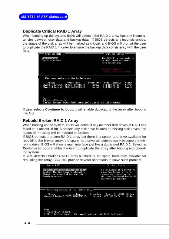
MS-6734 M-ATX Mainboard
4 - 8
Rebuild Broken RAID 1 ArrayWhen booting up the system, BIOS will detect if any member disk drives of RAID hasfailed or is absent. If BIOS detects any disk drive failures or missing disk drives, thestatus of the array will be marked as broken.If BIOS detects a broken RAID 1 array but there is a spare hard drive available forrebuilding the broken array, the spare hard drive will automatically become the mir-roring drive. BIOS will show a main interface just like a duplicated RAID 1. SelectingContinue to boot enables the user to duplicate the array after booting into operat-ing system.If BIOS detects a broken RAID 1 array but there is no spare hard drive available forrebuilding the array, BIOS will provide several operations to solve such problem.
Duplicate Critical RAID 1 ArrayWhen booting up the system, BIOS will detect if the RAID 1 array has any inconsis-tencies between user data and backup data. If BIOS detects any inconsistencies,the status of the disk array will be marked as critical, and BIOS will prompt the userto duplicate the RAID 1 in order to ensure the backup data consistency with the userdata.
If user selects Continue to boot, it will enable duplicating the array after bootinginto OS.

VIA VT8237 Serial ATA RAID Introduction
4 - 9
1. Power off and Check the Failed Drive:This item turns off the computer and replaces the failed hard drive with a good one.If your computer does not support APM, you must turn off your computer manually.After replacing the hard drive, boot into BIOS and select Choose replacementdrive and rebuild to rebuild the broken array.2. Destroy the Mirroring Relationship:This item cancels the data mirroring relationship of the broken array. For broken RAID1 arrays, the data on the surviving disk will remain after the destroy operation.However, Destroy the Mirroring Relationship is not recommend because thedata on the remaining disk will be lost when the hard drive is used to create anotherRAID 1 array.3. Choose Replacement Drive and Rebuild:This item enables users to select an already-connected hard drive to rebuild thebroken array. After choosing a hard drive, the channel column will be activated.
Highlight the target hard drive and press <Enter>, a warning message will appear.Press Y to use that hard drive to rebuild, or press N to cancel. Please note selectingoption Y will destroy all the data on the selected hard drive.4. Continue to boot:This item enables BIOS to skip the problem and continue booting into OS.

MS-6734 M-ATX Mainboard
4-10
Install Driver in Windows OS
New Windows OS (2000/XP/NT4) Installation The following details the installation of the drivers while installing Windows XP.
1. Start the installation:Boot from the CD-ROM. Press F6 when the message "Press F6 if you need
to install third party SCSI or RAID driver" appears.2. When the Windows Setup window is generated, press S to specify anAdditional Device(s).3. Insert the driver diskette VIA VT6420/VT8237 Disk Driver into drive A: andpress <Enter>.4. Depending on your operation system, choose VIA Serial ATA RAIDController(Windows XP), VIA Serial ATA RAID Controller(Windows 2000)or VIA Serial ATA RAID Controller(Windows NT4) from the list that appearson Windows XP Setup screen, press the <Enter> key.5. Press <Enter> to continue with installation or if you need to specify any addi-tional devices to be installed, do so at this time. Once all devices are specified,press <Enter> to continue with installation.6. From the Windows XP Setup screen, press the <Enter> key. Setup will nowload all device files and then continue the Windows XP installation
Existing Windows XP Driver Installation1. Insert the MSI CD into the CD-ROM drive.2. The CD will auto-run and the setup screen will appear.3. Under the Driver tab, click on VIA SATA RAID Utility.4. The drivers will be automatically installed.
Confirming Windows XP Driver Installation1. From Windows XP, open the Control Panel from My Computer followed bythe System icon.2. Choose the Hardware tab, then click the Device Manager tab.3. Click the "+" in front of the SCSI and RAID Controllers hardware type. Thedriver VIA IDE RAID Host Controller should appear.
Installing RAID Software & Drivers

VIA VT8237 Serial ATA RAID Introduction
4-11
Installation of VIA SATA RAID Utility
The VIA SATA RAID Utility is the software package that enables high-performanceRAID 0 arrays in the Windows* XP operating system. This version of VIA SATA RAIDUtility contains the following key features:
Serial ATA RAID driver for Windows XP VIA SATA RAID utility RAID0 and RAID1 functions
Insert the MSI CD and click on the VIA SATA RAID Utility to install the software.
The InstallShield Wizard will begin automatically for installation. Click on the Nextbutton to proceed the installation in the welcoming window.
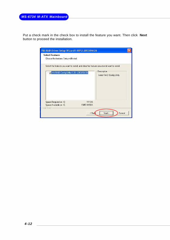
MS-6734 M-ATX Mainboard
4-12
Put a check mark in the check box to install the feature you want. Then click Nextbutton to proceed the installation.

VIA VT8237 Serial ATA RAID Introduction
4-13
Once the installation is complete, go to Start ---> Programs --->VIA --->raid_tool.exe to enable VIA RAID Tool.
After the software is finished installation, it will automati-cally started every time Windows is initiated. You maydouble-click on the icon shown in the system tray ofthe tool bar to launch the VIA RAID Tool utility.
Using VIA RAID Tool
The main interface is divided into two windows and the toolbar above contain themain functions. Click on these toolbar buttons to execute their specific functions.The left windowpane displays the controller and disk drives and the right window-pane displays the details of the controller or disk drives. The available features areas following:
View by Controller
View Event log
View by Devices
Help Topics

MS-6734 M-ATX Mainboard
4-14
Click on the plus (+) symbol next to Array 0---RAID 0 to see the details of each disk.
Click on o r button to determine the viewing type of left window pane.There are two viewing types: By controllers and by device. Click on the object in theleft window pane to display the status of the object in the right windowpane. Thefollowing screen shows the status of Array 0---RAID 0.

VIA VT8237 Serial ATA RAID Introduction
4-15
You may also use the same o r button to view the statuses of Array 0---RAID 1.
Click on the plus (+) symbol next to Array 0---RAID 1 to see the details of each disk.