klv1000 - v-strom riders international group
TRANSCRIPT

KLV1000
MotorcycleService Manual
KLV1000
MotorcycleService Manual
SupplementAll rights reserved. No parts of this publication may be reproduced, stored in a retrieval system, or
transmitted in any form or by any means, electronic mechanical photocopying, recording or otherwise, without the prior written permission of Quality Assurance Department/Consumer Products & Machinery Company/Kawasaki Heavy Industries, Ltd., Japan. No liability can be accepted for any inaccuracies or omissions in this publication, although every possible care has been taken to make it as complete and accurate as possible.
The right is reserved to make changes at any time without prior notice and without incurring an obligation to make such changes to products manufactured previously. See your Motorcycle dealer for the latest information on product improvements incorporated after this publication.
All information contained in this publication is based on the latest product information available at the time of publication. Illustrations and photographs in this publication are intended for reference use only and may not depict actual model component parts.
2004 Kawasaki Heavy Industries, Ltd. First Edition (1) Feb. 12, 2004 (K)


ForewordThis Kawasaki Service manual supplement
information provides unique to the Kawasaki KLV1000-A1, which is based on the Suzuki DL1000K4. It must be used in conjunction with the other chapters of this manual. Read both this supplement and the base manual for complete information on proper service procedures for the model covered by this manual.
This manual is designed primarily for use by trained mechanics in a properly equipped shop. However, it contains enough detail and basic information to make it useful to the owner who desires to perform his own basic maintenance and repair work. A basic knowledge of mechanics, the proper use of tools, and workshop procedures must be understood in order to carry out maintenance and repair satisfactorily. Whenever the owner has insufficient experience or doubts his ability to do the work, all adjustments, maintenance, and repair should be carried out only by qualified mechanics.
In order to perform the work efficiently and to avoid costly mistakes, read the text, thoroughly familiarize yourself with the procedures before starting work, and then do the work carefully in a clean area. Whenever special tools or equipment are specified, do not use makeshift tools or equipment. Precision measurements can only be made if the proper instruments are used.
For the duration of the warranty period, we recommend that all repairs and scheduled maintenance be performed in accordance with this service manual. Any owner maintenance or repair procedure not performed in accordance with this manual may void the warranty.
To get the longest life out of your motorcycle: Follow the Periodic Maintenance Chart in the Service Manual. Be alert for problems and non-scheduled maintenance. Use proper tools and genuine Kawasaki Motorcycle parts. Special tools, gauges, and testers that are necessary when servicing Kawasaki motorcycles are listed in this manual. Genuine parts provided as spare parts are listed in the Parts Catalog. Follow the procedures in this manual carefully. Don’t take shortcuts.
Remember to keep complete records of maintenance and repair with dates and any new parts installed.
How to Use This Manual In preparing this manual, the product was divided
into its major systems, and these systems became the manual’s chapters. All information for a particular system from adjustment through disassembly and inspection is located in a single chapter.
The Group Index shows you all of the product’s systems and assists in locating their chapters. Each chapter in turn has its own comprehensive Table of Contents.
For example, if you want crankshaft information, use the Group Index to locate the Engine chapter. Then, use the Table of Contents on the first page of the chapter to find the Crankshaft section.
Whenever you see these WARNING and CAUTION symbols, heed their instructions! Always follow safe operating and maintenance practices.
WARNING This warning symbol identified special instructions or procedures which, if not correctly followed, could result in personal injury, or loss of life.
CAUTION This caution symbol identifies special instructions or procedures which, if not strictly observed, could result in damage to or destruction of equipment.
This manual contains the other symbols (in addition to WARNING and CAUTION) which will help you distinguish different types of information.
NOTEThis note symbol indicates points of particular interest for more efficient and convenient operation.
Indicates a procedural step or work to be done.
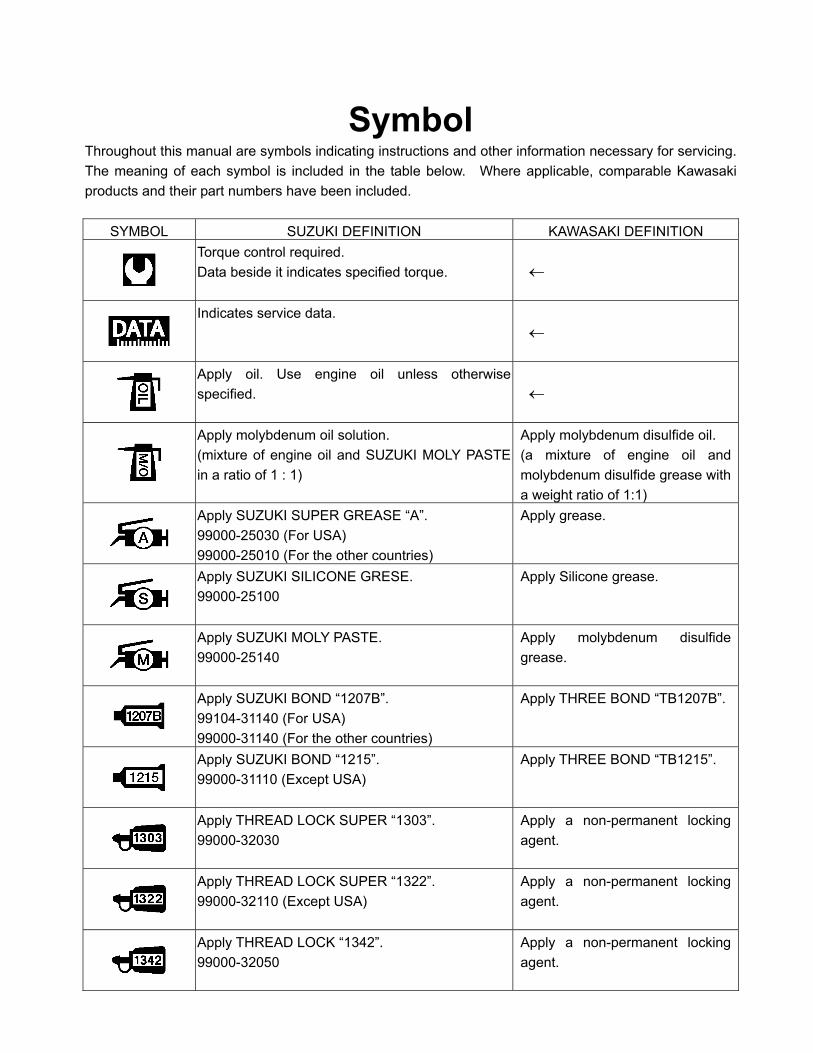
SymbolThroughout this manual are symbols indicating instructions and other information necessary for servicing. The meaning of each symbol is included in the table below. Where applicable, comparable Kawasaki products and their part numbers have been included.
SYMBOL SUZUKI DEFINITION KAWASAKI DEFINITION Torque control required. Data beside it indicates specified torque.
Indicates service data.
Apply oil. Use engine oil unless otherwise specified.
Apply molybdenum oil solution. (mixture of engine oil and SUZUKI MOLY PASTE in a ratio of 1 : 1)
Apply molybdenum disulfide oil. (a mixture of engine oil and molybdenum disulfide grease with a weight ratio of 1:1)
Apply SUZUKI SUPER GREASE “A”. 99000-25030 (For USA) 99000-25010 (For the other countries)
Apply grease.
Apply SUZUKI SILICONE GRESE. 99000-25100
Apply Silicone grease.
Apply SUZUKI MOLY PASTE. 99000-25140
Apply molybdenum disulfide grease.
Apply SUZUKI BOND “1207B”. 99104-31140 (For USA) 99000-31140 (For the other countries)
Apply THREE BOND “TB1207B”.
Apply SUZUKI BOND “1215”. 99000-31110 (Except USA)
Apply THREE BOND “TB1215”.
Apply THREAD LOCK SUPER “1303”. 99000-32030
Apply a non-permanent locking agent.
Apply THREAD LOCK SUPER “1322”. 99000-32110 (Except USA)
Apply a non-permanent locking agent.
Apply THREAD LOCK “1342”. 99000-32050
Apply a non-permanent locking agent.

SYMBOL SUZUKI DEFINITION KAWASAKI DEFINITION Apply or use brake fluid,
Measure in voltage range.
Measure in resistance range.
Measure in current range.
Measure in diode test range. Use a suitable commercially available digital multi meter for a diode tester and measure in diode test range.
Measure in continuity test range.
Use special tool. Refer to the special tools in Servicing Information chapter.
Use engine coolant. 99000-99032-11X (Except USA)
Use fork oil. 99000-99001-SS8
Front Fork Oil Viscosity SAE 10W-20
Use rear shock absorber oil. 99000-99001-S25

GENERAL INFORMATION 1-1
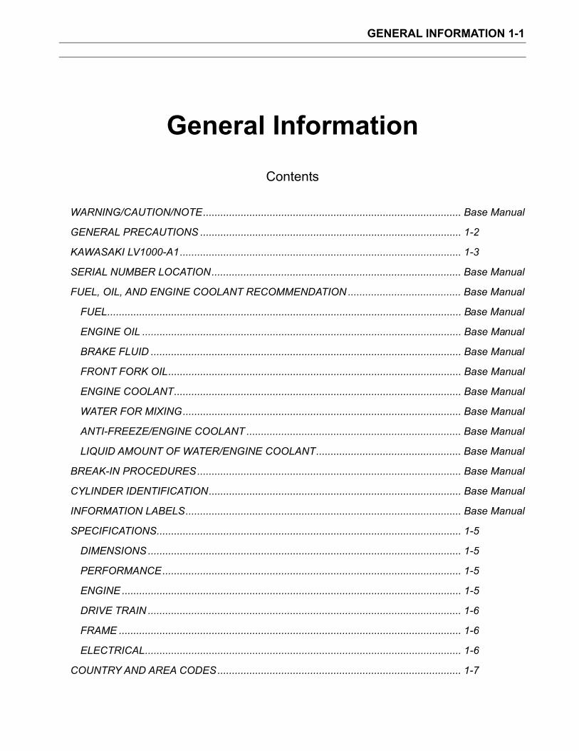
General Information
Contents
WARNING/CAUTION/NOTE......................................................................................... Base Manual
GENERAL PRECAUTIONS .......................................................................................... 1-2
KAWASAKI LV1000-A1................................................................................................. 1-3
SERIAL NUMBER LOCATION...................................................................................... Base Manual
FUEL, OIL, AND ENGINE COOLANT RECOMMENDATION ....................................... Base Manual
FUEL.......................................................................................................................... Base Manual
ENGINE OIL .............................................................................................................. Base Manual
BRAKE FLUID ........................................................................................................... Base Manual
FRONT FORK OIL..................................................................................................... Base Manual
ENGINE COOLANT................................................................................................... Base Manual
WATER FOR MIXING................................................................................................ Base Manual
ANTI-FREEZE/ENGINE COOLANT .......................................................................... Base Manual
LIQUID AMOUNT OF WATER/ENGINE COOLANT.................................................. Base Manual
BREAK-IN PROCEDURES........................................................................................... Base Manual
CYLINDER IDENTIFICATION....................................................................................... Base Manual
INFORMATION LABELS............................................................................................... Base Manual
SPECIFICATIONS......................................................................................................... 1-5
DIMENSIONS ............................................................................................................ 1-5
PERFORMANCE....................................................................................................... 1-5
ENGINE ..................................................................................................................... 1-5
DRIVE TRAIN ............................................................................................................ 1-6
FRAME ...................................................................................................................... 1-6
ELECTRICAL............................................................................................................. 1-6
COUNTRY AND AREA CODES.................................................................................... 1-7
GENERAL INFORMATION 1-2
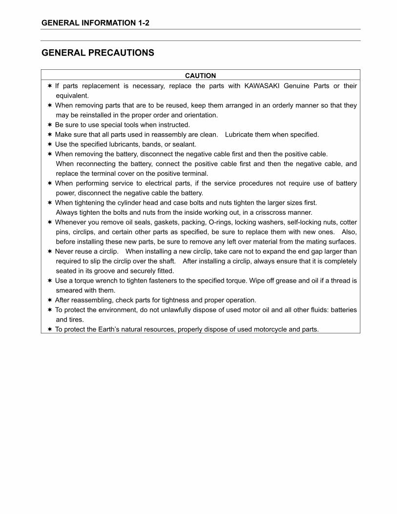
GENERAL PRECAUTIONS
CAUTIONIf parts replacement is necessary, replace the parts with KAWASAKI Genuine Parts or their equivalent.When removing parts that are to be reused, keep them arranged in an orderly manner so that they may be reinstalled in the proper order and orientation. Be sure to use special tools when instructed. Make sure that all parts used in reassembly are clean. Lubricate them when specified. Use the specified lubricants, bands, or sealant. When removing the battery, disconnect the negative cable first and then the positive cable. When reconnecting the battery, connect the positive cable first and then the negative cable, and replace the terminal cover on the positive terminal. When performing service to electrical parts, if the service procedures not require use of battery power, disconnect the negative cable the battery. When tightening the cylinder head and case bolts and nuts tighten the larger sizes first. Always tighten the bolts and nuts from the inside working out, in a crisscross manner. Whenever you remove oil seals, gaskets, packing, O-rings, locking washers, self-locking nuts, cotter pins, circlips, and certain other parts as specified, be sure to replace them with new ones. Also, before installing these new parts, be sure to remove any left over material from the mating surfaces.Never reuse a circlip. When installing a new circlip, take care not to expand the end gap larger than required to slip the circlip over the shaft. After installing a circlip, always ensure that it is completely seated in its groove and securely fitted. Use a torque wrench to tighten fasteners to the specified torque. Wipe off grease and oil if a thread is smeared with them. After reassembling, check parts for tightness and proper operation. To protect the environment, do not unlawfully dispose of used motor oil and all other fluids: batteries and tires. To protect the Earth’s natural resources, properly dispose of used motorcycle and parts.
GENERAL INFORMATION 1-3
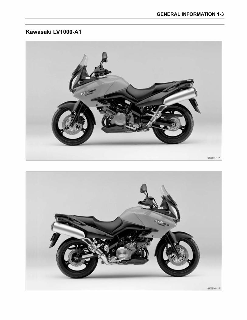
Kawasaki LV1000-A1
GENERAL INFORMATION 1-4
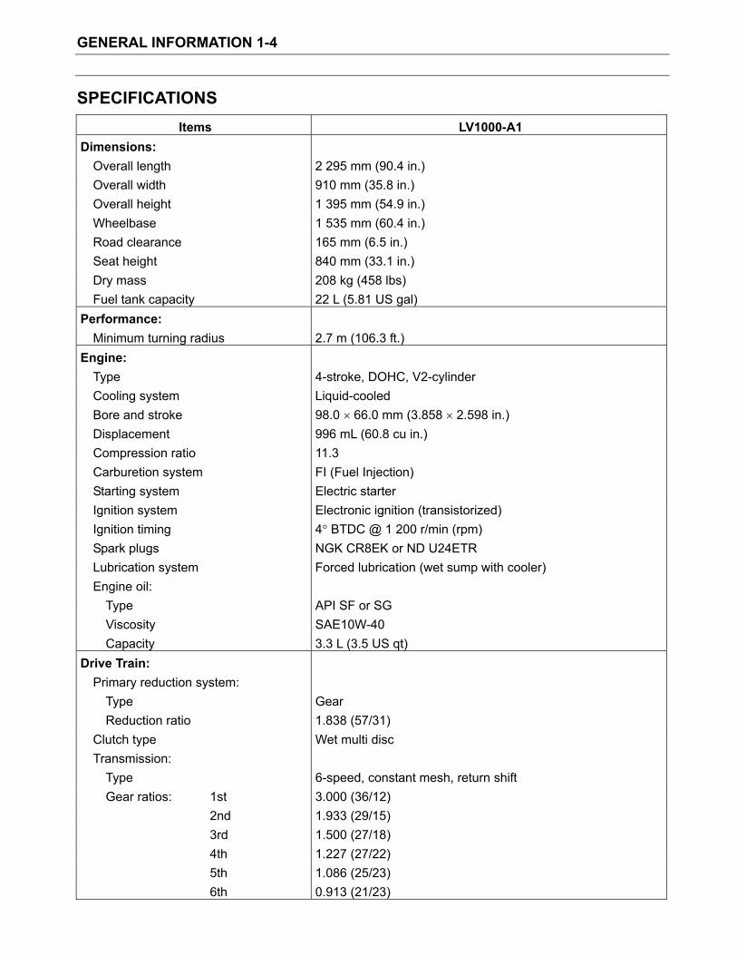
SPECIFICATIONS Items LV1000-A1
Dimensions:Overall length 2 295 mm (90.4 in.) Overall width 910 mm (35.8 in.) Overall height 1 395 mm (54.9 in.) Wheelbase 1 535 mm (60.4 in.) Road clearance 165 mm (6.5 in.) Seat height 840 mm (33.1 in.) Dry mass 208 kg (458 lbs) Fuel tank capacity 22 L (5.81 US gal)
Performance:Minimum turning radius 2.7 m (106.3 ft.)
Engine:Type 4-stroke, DOHC, V2-cylinder Cooling system Liquid-cooled Bore and stroke 98.0 66.0 mm (3.858 2.598 in.) Displacement 996 mL (60.8 cu in.) Compression ratio 11.3 Carburetion system FI (Fuel Injection) Starting system Electric starter Ignition system Electronic ignition (transistorized) Ignition timing 4 BTDC @ 1 200 r/min (rpm) Spark plugs NGK CR8EK or ND U24ETR Lubrication system Forced lubrication (wet sump with cooler) Engine oil:
Type API SF or SG Viscosity SAE10W-40 Capacity 3.3 L (3.5 US qt)
Drive Train: Primary reduction system:
Type Gear Reduction ratio 1.838 (57/31)
Clutch type Wet multi disc Transmission:
Type 6-speed, constant mesh, return shift Gear ratios: 1st 3.000 (36/12) 2nd 1.933 (29/15) 3rd 1.500 (27/18) 4th 1.227 (27/22) 5th 1.086 (25/23) 6th 0.913 (21/23)
GENERAL INFORMATION 1-5
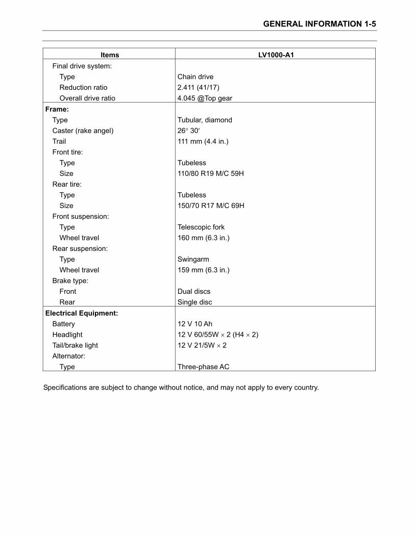
Items LV1000-A1 Final drive system:
Type Chain drive Reduction ratio 2.411 (41/17) Overall drive ratio 4.045 @Top gear
Frame:Type Tubular, diamond Caster (rake angel) 26 30Trail 111 mm (4.4 in.) Front tire:
Type Tubeless Size 110/80 R19 M/C 59H
Rear tire: Type Tubeless Size 150/70 R17 M/C 69H
Front suspension: Type Telescopic fork Wheel travel 160 mm (6.3 in.)
Rear suspension: Type Swingarm Wheel travel 159 mm (6.3 in.)
Brake type: Front Dual discs Rear Single disc
Electrical Equipment: Battery 12 V 10 Ah Headlight 12 V 60/55W 2 (H4 2) Tail/brake light 12 V 21/5W 2 Alternator:
Type Three-phase AC
Specifications are subject to change without notice, and may not apply to every country.
GENERAL INFORMATION 1-6
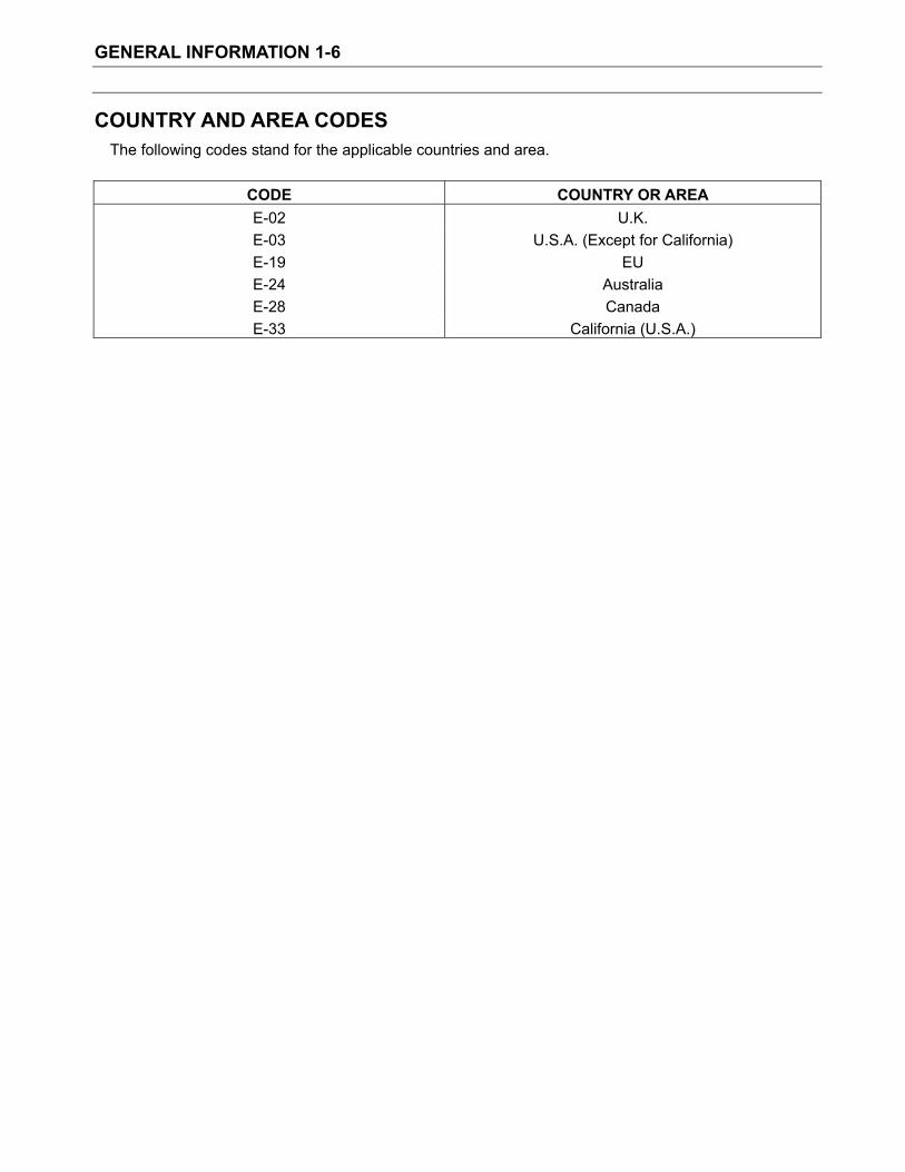
COUNTRY AND AREA CODES The following codes stand for the applicable countries and area.
CODE COUNTRY OR AREA E-02 U.K. E-03 U.S.A. (Except for California) E-19 EU E-24 Australia E-28 Canada E-33 California (U.S.A.)
PERIODIC MAINTENANCE 2-1
Periodic Maintenance Contents
PERIODIC MAINTENANCE SCHEDULE .................................................................... 2-2 PERIODIC MAINTENANCE CHART........................................................................ 2-2 VALVE CLEARANCE ADJUSTMENT CHART ......................................................... 2-3
MAINTENANCE AND TUNE-UP PROCEDURES ....................................................... Base Manual AIR CLEANER.......................................................................................................... Base ManualSPARK PLUG ........................................................................................................... Base ManualTAPPET CLEARANCE ............................................................................................. Base Manual FUEL HOSE.............................................................................................................. Base ManualENGINE OIL AND OIL FILTER ................................................................................. Base Manual ENGINE IDLE SPEED.............................................................................................. Base Manual THROTTLE CABLE PLAY ........................................................................................ Base Manual THROTTLE VALVE SYNCHRONIZATION ............................................................... Base Manual CLUTCH ................................................................................................................... Base ManualCOOLING SYSTEM ................................................................................................. Base Manual DRIVE CHAIN........................................................................................................... Base ManualBRAKES ................................................................................................................... Base ManualTIRE.......................................................................................................................... Base Manual STEERING ............................................................................................................... Base ManualFRONT FORK .......................................................................................................... Base ManualREAR SUSPENSION ............................................................................................... Base Manual EXHAUST PIPE BOLT.............................................................................................. Base Manual CHASSIS BOLT AND NUT ....................................................................................... Base Manual
COMPRESSION PRESSURE CHECK........................................................................ Base Manual COMPRESSION TEST PROCEDURE..................................................................... Base Manual
OIL PRESSURE CHECK ............................................................................................. Base Manual OIL PRESSURE TEST PROCEDURE ..................................................................... Base Manual

PERIODIC MAINTENANCE 2-2
PERIODIC MAINTENANCE SCHEDULE The chart below lists the recommended intervals for all the required periodic service work necessary to
keep the motorcycle operating at peak performance and economy. Maintenance intervals are expressed in terms of hours.
NOTEMore frequent servicing may be performed on motorcycles that are use under severe conditions.
Periodic Maintenance chart km 1 000 6 000 12 000 18 000 24 000 miles 600 4 000 7 500 11 000 15 000
Interval
Item months 1 6 12 18 24
Air cleaner element — I I R I Exhaust pipe bolts and muffler bolts T — T — T Valve clearance — — — — I Spark plugs — I R I R
— I I I I Fuel hose Replace every 4 years
Engine oil R R R R R Engine oil filter R — — R —
Idle speed I I I I I Throttle cable play I I I I I
— I — I Throttle valve synchronization I (E-33 only)
— — I — I Evaporative emission control system (E-33 only) Replace vapor hose every 4 years
PAIR(air supply)system — — I — I Engine coolant Replace every 2 years. Radiator hose — I I I I
— I I I I Clutch hose Replace every 4 years
— I I I I Clutch fluid Replace every 2 years
I I I I I Drive chain Clean and lublicate every 1 000 km (600 miles)
Brakes I I I I I — I I I I Brake hose
Replace every 4 years — I I I I Brake fluid
Replace every 2 years Tires — I I I I Steering I — I — I Front fork — — I — I Rear suspension — — I — I Chassis bolts and nuts T T T T T
I=Inspect and clean, adjust, replace or lubricate as necessary R=Replace T=Tighten C=Clean

PERIODIC MAINTENANCE 2-3
VALVE CLEARANCE ADJUSTMENT CHART INLET VALVE
INLET PRESENT SHIM
Part No. (92180) S018 S019 S020 S021 S022 S023 S024 S025 S026 S027 S028 S029 S030 S031 S032 S033 S034 S035 S036 S037 S038 S039 S040 S041 S042
MARK and THICKNESS (mm)
2.30 2.35 2.40 2.45 2.50 2.55 2.60 2.65 2.70 2.75 2.80 2.85 2.90 2.95 3.00 3.05 3.10 3.15 3.20 3.25 3.30 3.35 3.40 3.45 3.50
0.00 ~ 0.04 2.30 2.35 2.40 2.45 2.50 2.55 2.60 2.65 2.70 2.75 2.80 2.85 2.90 2.95 3.00 3.05 3.10 3.15 3.20 3.25 3.30 3.35 3.400.05 ~ 0.09 2.30 2.35 2.40 2.45 2.50 2.55 2.60 2.65 2.70 2.75 2.80 2.85 2.90 2.95 3.00 3.05 3.10 3.15 3.20 3.25 3.30 3.35 3.40 3.450.10 ~ 0.20 SPECIFIED CLEARANCE/NO CHANGE REQUIRED
Exa
mpl
e
0.21 ~ 0.25 2.40 2.45 2.50 2.55 2.60 2.65 2.70 2.75 2.80 2.85 2.90 2.95 3.00 3.05 3.10 3.15 3.20 3.25 3.30 3.35 3.40 3.45 3.50 3.50
0.26 ~ 0.30 2.45 2.50 2.55 2.60 2.65 2.70 2.75 2.80 2.85 2.90 2.95 3.00 3.05 3.10 3.15 3.20 3.25 3.30 3.35 3.40 3.45 3.50 3.50 0.31 ~ 0.35 2.50 2.55 2.60 2.65 2.70 2.75 2.80 2.85 2.90 2.95 3.00 3.05 3.10 3.15 3.20 3.25 3.30 3.35 3.40 3.45 3.50 3.50 0.36 ~ 0.40 2.55 2.60 2.65 2.70 2.75 2.80 2.85 2.90 2.95 3.00 3.05 3.10 3.15 3.20 3.25 3.30 3.35 3.40 3.45 3.50 3.50 0.41 ~ 0.45 2.60 2.65 2.70 2.75 2.80 2.85 2.90 2.95 3.00 3.05 3.10 3.15 3.20 3.25 3.30 3.35 3.40 3.45 3.50 3.50 0.46 ~ 0.50 2.65 2.70 2.75 2.80 2.85 2.90 2.95 3.00 3.05 3.10 3.15 3.20 3.25 3.30 3.35 3.40 3.45 3.50 3.50 0.51 ~ 0.55 2.70 2.75 2.80 2.85 2.90 2.95 3.00 3.05 3.10 3.15 3.20 3.25 3.30 3.35 3.40 3.45 3.50 3.50 0.56 ~ 0.60 2.75 2.80 2.85 2.90 2.95 3.00 3.05 3.10 3.15 3.20 3.25 3.30 3.35 3.40 3.45 3.50 3.50 0.61 ~ 0.65 2.80 2.85 2.90 2.95 3.00 3.05 3.10 3.15 3.20 3.25 3.30 3.35 3.40 3.45 3.50 3.50 0.66 ~ 0.70 2.85 2.90 2.95 3.00 3.05 3.10 3.15 3.20 3.25 3.30 3.35 3.40 3.45 3.50 3.50 0.71 ~ 0.75 2.90 2.95 3.00 3.05 3.10 3.15 3.20 3.25 3.30 3.35 3.40 3.45 3.50 3.50 0.76 ~ 0.80 2.95 3.00 3.05 3.10 3.15 3.20 3.25 3.30 3.35 3.40 3.45 3.50 3.50 0.81 ~ 0.85 3.00 3.05 3.10 3.15 3.20 3.25 3.30 3.35 3.40 3.45 3.50 3.50 0.86 ~ 0.90 3.05 3.10 3.15 3.20 3.25 3.30 3.35 3.40 3.45 3.50 3.50 0.91 ~ 0.95 3.10 3.15 3.20 3.25 3.30 3.35 3.40 3.45 3.50 3.50 0.96 ~ 1.00 3.15 3.20 3.25 3.30 3.35 3.40 3.45 3.50 3.50 1.01 ~ 1.05 3.20 3.25 3.30 3.35 3.40 3.45 3.50 3.50 1.06 ~ 1.10 3.25 3.30 3.35 3.40 3.45 3.50 3.50 1.11 ~ 1.15 3.30 3.35 3.40 3.45 3.50 3.50 INSTALL THE SHIM OF THIS THICKNESS (mm) 1.16 ~ 1.20 3.35 3.40 3.45 3.50 3.50 1.21 ~ 1.25 3.40 3.45 3.50 3.50 1.26 ~ 1.30 3.45 3.50 3.50
VALV
E C
LEAR
ANC
E M
EA
SUR
EM
ENT
(mm
)
1.31 ~ 1.35 3.50 3.50 1.36 ~ 1.40 3.50
1. Measure the clearance (when engine is cold.) 2. Check present shim size. 3. Match clearance in vertical column with present shim size in horizontal column. 4. Install the shim specified where the lines intersect. This shim will give the proper clearance.
Example : Present shim is 2.70 mm. Measured clearance is 0.23 mm. Replace 2.70 mm shim with 2.80 mm shim.
5. Remeasure the valve clearance and readjust if necessary.
PERIODIC MAINTENANCE 2-4
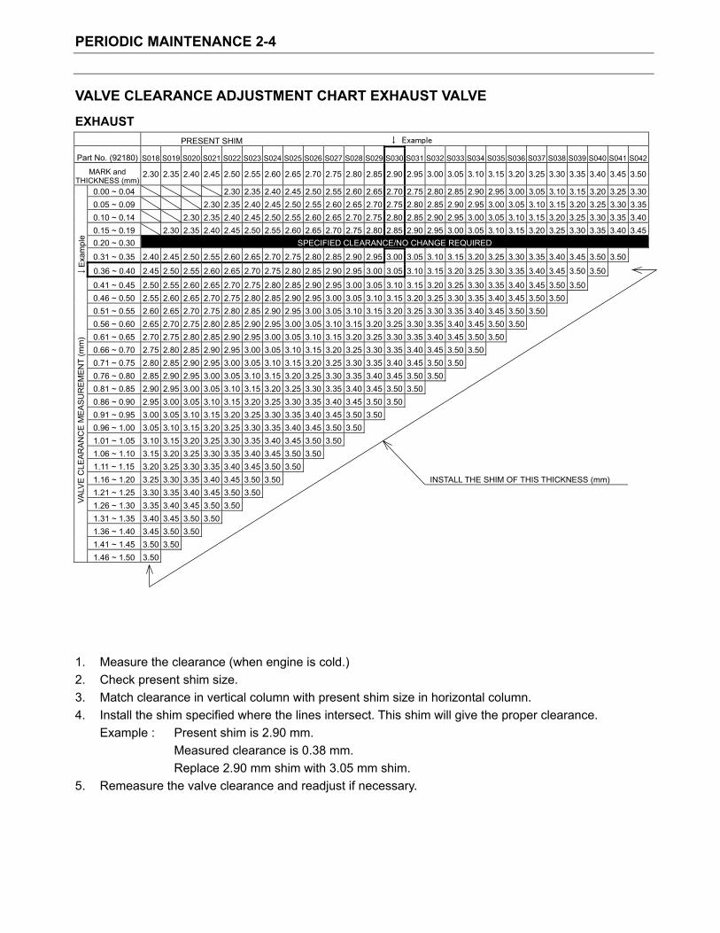
VALVE CLEARANCE ADJUSTMENT CHART EXHAUST VALVE
EXHAUST PRESENT SHIM
Part No. (92180) S018 S019 S020 S021 S022 S023 S024 S025 S026 S027 S028 S029 S030 S031 S032 S033 S034 S035 S036 S037 S038 S039 S040 S041 S042
MARK and THICKNESS (mm)
2.30 2.35 2.40 2.45 2.50 2.55 2.60 2.65 2.70 2.75 2.80 2.85 2.90 2.95 3.00 3.05 3.10 3.15 3.20 3.25 3.30 3.35 3.40 3.45 3.50
0.00 ~ 0.04 2.30 2.35 2.40 2.45 2.50 2.55 2.60 2.65 2.70 2.75 2.80 2.85 2.90 2.95 3.00 3.05 3.10 3.15 3.20 3.25 3.300.05 ~ 0.09 2.30 2.35 2.40 2.45 2.50 2.55 2.60 2.65 2.70 2.75 2.80 2.85 2.90 2.95 3.00 3.05 3.10 3.15 3.20 3.25 3.30 3.350.10 ~ 0.14 2.30 2.35 2.40 2.45 2.50 2.55 2.60 2.65 2.70 2.75 2.80 2.85 2.90 2.95 3.00 3.05 3.10 3.15 3.20 3.25 3.30 3.35 3.400.15 ~ 0.19 2.30 2.35 2.40 2.45 2.50 2.55 2.60 2.65 2.70 2.75 2.80 2.85 2.90 2.95 3.00 3.05 3.10 3.15 3.20 3.25 3.30 3.35 3.40 3.450.20 ~ 0.30 SPECIFIED CLEARANCE/NO CHANGE REQUIRED
0.31 ~ 0.35 2.40 2.45 2.50 2.55 2.60 2.65 2.70 2.75 2.80 2.85 2.90 2.95 3.00 3.05 3.10 3.15 3.20 3.25 3.30 3.35 3.40 3.45 3.50 3.50
Exa
mpl
e
0.36 ~ 0.40 2.45 2.50 2.55 2.60 2.65 2.70 2.75 2.80 2.85 2.90 2.95 3.00 3.05 3.10 3.15 3.20 3.25 3.30 3.35 3.40 3.45 3.50 3.50
0.41 ~ 0.45 2.50 2.55 2.60 2.65 2.70 2.75 2.80 2.85 2.90 2.95 3.00 3.05 3.10 3.15 3.20 3.25 3.30 3.35 3.40 3.45 3.50 3.50 0.46 ~ 0.50 2.55 2.60 2.65 2.70 2.75 2.80 2.85 2.90 2.95 3.00 3.05 3.10 3.15 3.20 3.25 3.30 3.35 3.40 3.45 3.50 3.50 0.51 ~ 0.55 2.60 2.65 2.70 2.75 2.80 2.85 2.90 2.95 3.00 3.05 3.10 3.15 3.20 3.25 3.30 3.35 3.40 3.45 3.50 3.50 0.56 ~ 0.60 2.65 2.70 2.75 2.80 2.85 2.90 2.95 3.00 3.05 3.10 3.15 3.20 3.25 3.30 3.35 3.40 3.45 3.50 3.50 0.61 ~ 0.65 2.70 2.75 2.80 2.85 2.90 2.95 3.00 3.05 3.10 3.15 3.20 3.25 3.30 3.35 3.40 3.45 3.50 3.50 0.66 ~ 0.70 2.75 2.80 2.85 2.90 2.95 3.00 3.05 3.10 3.15 3.20 3.25 3.30 3.35 3.40 3.45 3.50 3.50 0.71 ~ 0.75 2.80 2.85 2.90 2.95 3.00 3.05 3.10 3.15 3.20 3.25 3.30 3.35 3.40 3.45 3.50 3.50 0.76 ~ 0.80 2.85 2.90 2.95 3.00 3.05 3.10 3.15 3.20 3.25 3.30 3.35 3.40 3.45 3.50 3.50 0.81 ~ 0.85 2.90 2.95 3.00 3.05 3.10 3.15 3.20 3.25 3.30 3.35 3.40 3.45 3.50 3.50 0.86 ~ 0.90 2.95 3.00 3.05 3.10 3.15 3.20 3.25 3.30 3.35 3.40 3.45 3.50 3.50 0.91 ~ 0.95 3.00 3.05 3.10 3.15 3.20 3.25 3.30 3.35 3.40 3.45 3.50 3.50 0.96 ~ 1.00 3.05 3.10 3.15 3.20 3.25 3.30 3.35 3.40 3.45 3.50 3.50 1.01 ~ 1.05 3.10 3.15 3.20 3.25 3.30 3.35 3.40 3.45 3.50 3.50 1.06 ~ 1.10 3.15 3.20 3.25 3.30 3.35 3.40 3.45 3.50 3.50 1.11 ~ 1.15 3.20 3.25 3.30 3.35 3.40 3.45 3.50 3.50 1.16 ~ 1.20 3.25 3.30 3.35 3.40 3.45 3.50 3.50 INSTALL THE SHIM OF THIS THICKNESS (mm) 1.21 ~ 1.25 3.30 3.35 3.40 3.45 3.50 3.50 1.26 ~ 1.30 3.35 3.40 3.45 3.50 3.50 1.31 ~ 1.35 3.40 3.45 3.50 3.50 1.36 ~ 1.40 3.45 3.50 3.50
VALV
E C
LEAR
ANC
E M
EA
SUR
EM
ENT
(mm
)
1.41 ~ 1.45 3.50 3.50 1.46 ~ 1.50 3.50
1. Measure the clearance (when engine is cold.) 2. Check present shim size. 3. Match clearance in vertical column with present shim size in horizontal column. 4. Install the shim specified where the lines intersect. This shim will give the proper clearance.
Example : Present shim is 2.90 mm. Measured clearance is 0.38 mm. Replace 2.90 mm shim with 3.05 mm shim.
5. Remeasure the valve clearance and readjust if necessary.

ENGINE 3-1
EngineContents
ENGINE COMPONENTS REMOVABLE WITH ENGINE IN PLACE ...........................Base Manual ENGINE LEFT SIDE.................................................................................................Base Manual ENGINE RIGHT SIDE...............................................................................................Base Manual ENGINE CENTER ....................................................................................................Base Manual
ENGINE REMOVAL AND REMOUNTING ...................................................................Base Manual ENGINE REMOVAL..................................................................................................Base Manual ENGINE REMOUNTING ..........................................................................................Base Manual
ENGINE DISASSEMBLY .............................................................................................Base Manual ENGINE COMPONENTS INSPECTION AND SERVICE.............................................Base Manual
CYLINDER HEAD.....................................................................................................Base Manual CAMSHAFT/AUTOMATIC DECOMPRESSION ASSEMBLY ...................................Base Manual CYLINDER................................................................................................................Base ManualPISTON AND PISTON RING....................................................................................Base Manual CONROD..................................................................................................................Base ManualCRANKSHAFT .........................................................................................................Base Manual STARTER CLUTCH..................................................................................................Base Manual STARTER TORQUE LIMITER..................................................................................Base Manual OIL PUMP.................................................................................................................Base ManualCLUTCH ...................................................................................................................Base ManualGEARSHIFT FORK AND GEAR...............................................................................Base Manual TRANSMISSION ......................................................................................................Base Manual BEARINGS ...............................................................................................................Base ManualOIL SEALS ...............................................................................................................Base Manual
ENGINE REASSEMBLY ..............................................................................................Base Manual CRANKSHAFT .........................................................................................................Base Manual GEARSHIFT CAM AND FORK.................................................................................Base Manual CRANKCASE ...........................................................................................................Base ManualSTARTER CLUTCH AND GENERATOR ROTOR....................................................Base Manual BALANCER SHAFT..................................................................................................Base Manual PRIMARY DRIVE GEAR ..........................................................................................Base Manual GEARSHIFT CAM DRIVEN GEAR...........................................................................Base Manual GEARSHIFT SHAFT.................................................................................................Base Manual OIL PUMP.................................................................................................................Base ManualCAM CHAIN..............................................................................................................Base ManualCLUTCH ...................................................................................................................Base ManualRIGHT CRANKCASE COVER..................................................................................Base Manual CLUTCH COVER .....................................................................................................Base Manual GENERATOR ROTOR COVER................................................................................Base Manual STARTER DRIVE GEAR COVER ............................................................................Base Manual PISTON RING...........................................................................................................Base ManualPISTON AND CYLINDER.........................................................................................Base Manual CYLINDER HEAD.....................................................................................................Base Manual CAMSHAFT/AUTOMATIC DECOMPRESSION ASSEMBLY ...................................Base Manual CYLINDER HEAD COVER.......................................................................................Base Manual CAM CHAIN TENSION ADJUSTER.........................................................................Base Manual

ENGINE 3-2
FI SYSTEM 4-1
FI System Contents
PRECAUTIONS IN SERVICING................................................................................... Base Manual CONNECTOR/COUPLER ......................................................................................... Base Manual FUSE ......................................................................................................................... Base Manual ECM/VARIOUS SENSORS ....................................................................................... Base Manual ELECTRICAL CIRCUIT INSPECTION PROCEDURE .............................................. Base Manual
FI SYSTEM TECHNICAL FEATURES .......................................................................... Base Manual INJECTION TIME (INJECTION VOLUME)................................................................ Base Manual COMPENSATION OF INJECTION TIME (VOLUME) ................................................ Base Manual INJECTION STOP CONTROL................................................................................... Base Manual FUEL DELIVERY SYSTEM ....................................................................................... Base Manual FUEL PUMP .............................................................................................................. Base ManualFUEL PRESSURE REGULATOR.............................................................................. Base Manual FUEL INJECTOR....................................................................................................... Base ManualFUEL PUMP CONTROL SYSTEM ............................................................................ Base Manual ECM (FI CONTROL UNIT) ........................................................................................ Base Manual INJECTION TIMING .................................................................................................. Base Manual SENSORS ................................................................................................................. Base Manual
FI SYSTEM PARTS LOCATION ................................................................................... Base Manual FI SYSTEM WIRING DIAGRAM ................................................................................... Base Manual SELF-DIAGNOSIS FUNCTION..................................................................................... Base Manual
USER MODE ........................................................................................................... Base ManualDEALER MODE......................................................................................................... Base ManualTPS ADJUSTMENT................................................................................................... Base Manual
FAIL-SAFE FUNCTION................................................................................................. Base Manual FI SYSTEM TROUBLESHOOTING .............................................................................. Base Manual
CUSTOMER COMPLAINT ANALYSIS ...................................................................... Base Manual SELF-DIAGNOSTIC PROCEDURES........................................................................ Base Manual SELF-DIAGNOSIS RESET PROCEDURE................................................................ Base Manual MALFUNCTION CODE AND DEFECTIVE CONDITION........................................... Base Manual “C11” CMP SENSOR CIRCUIT MALFUNCTION....................................................... Base Manual “C12” CKP SENSOR CIRCUIT MALFUNCTION....................................................... Base Manual “C13” IAP SENSOR CIRCUIT MALFUNCTION......................................................... Base Manual “C14” TP SENSOR CIRCUIT MALFUNCTION.......................................................... Base Manual “C15” ECT SENSOR CIRCUIT MALFUNCTION ....................................................... Base Manual “C21” IAT SENSOR CIRCUIT MALFUNCTION......................................................... Base Manual “C22” AP SENSOR CIRCUIT MALFUNCTION.......................................................... Base Manual “C23” TO SENSOR CIRCUIT MALFUNCTION ......................................................... Base Manual “C24” or “25” IGNITION SYSTEM MALFUNCTION................................................... Base Manual “C28” STV ACTUATOR CIRCUIT MALFUNCTION ................................................... Base Manual “C29” STP SENSOR CIRCUIT MALFUNCTION ....................................................... Base Manual “C31” GEAR POSITION (GP) SWITCH CIRCUIT MALFUNCTION .......................... Base Manual “C32” or “C33” FUEL INJECTION MALFUNCTION................................................... Base Manual “C41” FP RELAY CIRCUIT MALFUNCTION ............................................................. Base Manual
FI SYSTEM 4-2
“C42” IG SWITCH CIRCUIT MALFUNCTION ........................................................... Base Manual “C44” HO2 SENSOR (HO2S) CIRCUIT MALFUNCTION ........................................... Base Manual
FUEL SYSTEM ............................................................................................................. Base ManualFUEL TANK LIFT-UP ................................................................................................. Base Manual FUEL TANK REMOVAL ............................................................................................. Base Manual FUEL TANK INSTALLATION ..................................................................................... Base Manual FUEL PRESSURE INSPECTION.............................................................................. Base Manual FUEL PUMP INSPECTION ....................................................................................... Base Manual FUEL PUMP RELAY INSPECTION ........................................................................... Base Manual FUEL PUMP AND FUEL FILTER REMOVAL ............................................................ Base Manual FUEL MESH FILTER INSPECTION AND CLEANING .............................................. Base Manual FUEL PUMP AND FUEL MESH FILTER INSTALLATION ......................................... Base Manual
THROTTLE BODY AND STV ACTUATOR ................................................................... Base Manual CONSTRUCTION...................................................................................................... Base Manual THROTTLE BODY REMOVAL .................................................................................. Base Manual THROTTLE BODY DISASSEMBLY........................................................................... Base Manual THROTTLE BODY CLEANING ................................................................................. Base Manual INSPECTION............................................................................................................. Base ManualTHROTTLE BODY REASSEMBLY............................................................................ Base Manual STP SENSOR ADJUSTMENT................................................................................... Base Manual THROTTLE BODY INSTALLATION........................................................................... Base Manual TP SENSOR ADJUSTMENT ..................................................................................... Base Manual FUEL INJECTOR INSPECTION................................................................................ Base Manual FUEL INJECTOR INSTALLATION............................................................................. Base Manual FAST IDLE INSPECTION.......................................................................................... Base Manual FAST IDLE ADJUSTMENT........................................................................................ Base Manual THROTTLE VALVE SYNCHRONIZATION ................................................................ Base Manual THROTTLE CABLE ADJUSTMENT .......................................................................... Base Manual
SENSOR ....................................................................................................................... Base Manual IAP SENSOR INSPECTION ...................................................................................... Base Manual IAP SENSOR REMOVAL/INSTALLATION................................................................. Base Manual TP SENSOR INSPECTION ....................................................................................... Base Manual TP SENSOR REMOVAL/INSTALLATION.................................................................. Base Manual STP SENSOR INSPECTION..................................................................................... Base Manual STP SENSOR REMOVAL/INSTALLATION ............................................................... Base Manual CKP SENSOR INSPECTION .................................................................................... Base Manual CKP SENSOR REMOVAL/INSTALLATION............................................................... Base Manual CMP SENSOR INSPECTION.................................................................................... Base Manual CMP SENSOR REMOVAL/INSTALLATION .............................................................. Base Manual IAT SENSOR INSPECTION ...................................................................................... Base Manual IAT SENSOR REMOVAL/INSTALLATION................................................................. Base Manual ECT SENSOR INSPECTION..................................................................................... Base Manual ECT SENSOR REMOVAL/INSTALLATION ............................................................... Base Manual AP SENSOR INSPECTION....................................................................................... Base Manual AP SENSOR REMOVAL/INSTALLATION.................................................................. Base Manual TO SENSOR INSPECTION....................................................................................... Base Manual TO SENSOR REMOVAL/INSTALLATION ................................................................. Base Manual HO2 SENSOR INSPECTION ..................................................................................... Base Manual HO2 SENSOR REMOVAL/INSTALLATION................................................................ Base Manual

COOLING SYSTEM 5-1
Cooling System
Contents
ENGINE COOLANT ...................................................................................................... Base Manual
COOLING CIRCUIT ...................................................................................................... Base Manual
COOLING CIRCUIT INSPECTION............................................................................ Base Manual
RADIATOR .................................................................................................................... Base Manual
REMOVAL ................................................................................................................. Base Manual
INSPECTION AND CLEANING ................................................................................. Base Manual
INSTALLATION.......................................................................................................... Base Manual
RADIATOR RESERVOIR TANK.................................................................................... Base Manual
REMOVAL./INSTALLATION ...................................................................................... Base Manual
RADIATOR CAP............................................................................................................ Base Manual
INSPECTION............................................................................................................. Base Manual
WATER HOSE .............................................................................................................. Base Manual
INSPECTION............................................................................................................. Base Manual
COOLING FAN.............................................................................................................. Base Manual
REMOVAL ................................................................................................................. Base Manual
INSPECTION............................................................................................................. Base Manual
INSTALLATION.......................................................................................................... Base Manual
COOLING FAN THERMO-SWITCH.............................................................................. Base Manual
REMOVAL ................................................................................................................. Base Manual
INSPECTION............................................................................................................. Base Manual
INSTALLATION.......................................................................................................... Base Manual
ENGINE COOLANT TEMPERATURE SENSOR .......................................................... Base Manual
REMOVAL ................................................................................................................. Base Manual
INSPECTION............................................................................................................. Base Manual
INSTALLATION.......................................................................................................... Base Manual
COOLING SYSTEM 5-2
THERMOSTAT .............................................................................................................. Base Manual
REMOVAL ................................................................................................................. Base Manual
INSPECTION............................................................................................................. Base Manual
INSTALLATION.......................................................................................................... Base Manual
WATER PUMP .............................................................................................................. Base Manual
REMOVAL AND DISASSEMBLY ............................................................................... Base Manual
INSPECTION............................................................................................................. Base Manual
REASSEMBLY AND INSTALLATION ........................................................................ Base Manual
LUBRICATION SYSTEM............................................................................................... Base Manual
OIL PRESSURE ........................................................................................................ Base Manual
OIL FILTER................................................................................................................ Base Manual
OIL PRESSURE REGULATOR ................................................................................. Base Manual
OIL STRAINER.......................................................................................................... Base Manual
OIL JET...................................................................................................................... Base Manual
OIL PUMP.................................................................................................................. Base Manual
OIL PRESSURE SWITCH ......................................................................................... Base Manual
OIL COOLER ................................................................................................................ Base Manual
REMOVAL ................................................................................................................. Base Manual
INSPECTION AND CLEANING ................................................................................. Base Manual
INSTALLATION.......................................................................................................... Base Manual
ENGINE LUBRICATION FLOW CHART....................................................................... Base Manual
ENGINE LUBRICATION CIRCUIT ................................................................................ Base Manual

CHASSIS 6-1
ChassisContents
EXTERIOR PARTS.........................................................................................Base Manual CONSTRUCTION........................................................................................Base ManualREMOVAL ...................................................................................................Base Manual
FRONT WHEEL .............................................................................................Base ManualCONSTRUCTION........................................................................................Base ManualREMOVAL ...................................................................................................Base Manual INSPECTION AND DISASSEMBLY ............................................................Base Manual REASSEMBLY AND REMOUNTING...........................................................Base Manual
FRONT FORK ................................................................................................Base Manual CONSTRUCTION........................................................................................Base ManualREMOVAL AND DISASSEMBLY.................................................................Base Manual INSPECTION ..............................................................................................Base Manual REASSEMBLY AND REMOUNTING...........................................................Base Manual
STEERING AND HANDLEBAR......................................................................Base Manual CONSTRUCTION........................................................................................Base ManualREMOVAL ...................................................................................................Base Manual INSPECTION AND DISASSEMBLY ............................................................Base Manual REASSEMBLY AND REMOUNTING...........................................................Base Manual STEERING TENSION ADJUSTMENT ........................................................Base Manual
REAR WHEEL................................................................................................Base Manual CONSTRUCTION........................................................................................Base ManualREMOVAL ...................................................................................................Base Manual INSPECTION AND DISASSEMBLY ............................................................Base Manual REASSEMBLY AND REMOUNTING...........................................................Base Manual
REAR SHOCK ABSORBER ...........................................................................Base ManualCONSTRUCTION........................................................................................Base ManualREMOVAL ...................................................................................................Base Manual INSPECTION ..............................................................................................Base Manual REAR SHOCK ABSORBER DISPOSAL .....................................................Base ManualREMOUNTING............................................................................................Base ManualSUSPENSION SETTING ............................................................................Base Manual
REAR SWINGARM ........................................................................................Base Manual CONSTRUCTION........................................................................................Base ManualREMOVAL ...................................................................................................Base Manual INSPECTION AND DISASSEMBLY ............................................................Base Manual REASSEMBLY ............................................................................................Base ManualREMOUNTING............................................................................................Base ManualFINAL INSPECTION AND ADJUSTMENT ..................................................Base Manual
CHASSIS 6-2
FRONT BRAKE ..............................................................................................Base Manual CONSTRUCTION........................................................................................Base ManualBRAKE PAD REPLACEMENT ....................................................................Base ManualBRAKE FLUID REPLACEMENT .................................................................Base Manual CALIPER REMOVAL AND DISASSEMBLY.................................................Base Manual CALIPER INSPECTION ..............................................................................Base ManualCALIPER REASSEMBLY AND REMOUNTING ..........................................Base Manual BRAKE DISC INSPECTION........................................................................Base ManualMASTER CYLINDER REMOVAL AND DISASSEMBLY..............................Base Manual MASTER CYLINDER INSPECTION............................................................Base Manual MASTER CYLINDER REASSEMBLY AND REMOUNTING........................Base Manual
REAR BRAKE ................................................................................................Base Manual CONSTRUCTION........................................................................................Base ManualBRAKE PAD REPLACEMENT ....................................................................Base ManualBRAKE FLUID REPLACEMENT .................................................................Base Manual CALIPER REMOVAL AND DISASSEMBLY.................................................Base Manual CALIPER INSPECTION ..............................................................................Base ManualBRAKE DISC INSPECTION........................................................................Base ManualCALIPER REASSEMBLY AND REMOUNTING ..........................................Base Manual MASTER CYLINDER REMOVAL AND DISASSEMBLY..............................Base Manual MASTER CYLINDER INSPECTION............................................................Base Manual MASTER CYLINDER REASSEMBLY AND REMOUNTING........................Base Manual
CLUTCH RELEASE CYLINDER AND MASTER CYLINDER .........................Base Manual CONSTRUCTION........................................................................................Base ManualCLUTCH FLUID REPLACEMENT...............................................................Base Manual CLUTCH RELEASE CYLINDER REMOVAL AND DISASSEMBLY.............Base Manual CLUTCH RELEASE CYLINDER INSPECTION ..........................................Base Manual CLUTCH RELEASE CYLINDER REASSEMBLY AND REMOUNTING.......Base Manual CLUTCH MASTER CYLINDER REMOVAL AND DISASSEMBLY ..............Base Manual CLUTCH MASTER CYLINDER INSPECTION ............................................Base ManualCLUTCH MASTER CYLINDER REASSEMBLY AND REMOUNTING ........Base Manual
TIRE AND WHEEL .........................................................................................Base Manual TIRE REMOVAL..........................................................................................Base Manual INSPECTION ..............................................................................................Base ManualVALVE INSTALLATION ...............................................................................Base ManualTIRE INSTALLATION ..................................................................................Base Manual

ELECTRICAL SYSTEM 7-1
Electrical System Contents
CAUTIONS IN SERVICING ......................................................................................... Base Manual CONNECTORS ........................................................................................................ Base Manual COUPLERS .............................................................................................................. Base ManualCLAMPS ................................................................................................................... Base ManualFUSE ........................................................................................................................ Base Manual SEMI-CONDUCTOR EQUIPPED PARTS ................................................................ Base Manual BATTERY.................................................................................................................. Base ManualCONNECTING THE BATTERY ................................................................................ Base Manual WIRING PROCEDURE ............................................................................................ Base Manual USING THE MULTI CIRCUIT TESTER .................................................................... Base Manual
LOCATION OF ELECTRICAL COMPONENTS ........................................................... Base Manual CHARGING SYSTEM .................................................................................................. Base Manual
TROUBLESHOOTING.............................................................................................. Base Manual INSPECTION............................................................................................................ Base Manual
STARTER SYSTEM AND SIDE-STAND/IGNITION INTERLOCK SYSTEM................ Base Manual TROUBLESHOOTING.............................................................................................. Base Manual STARTER MOTOR REMOVAL AND DISASSEMBLY .............................................. Base Manual STARTER MOTOR INSPECTION ............................................................................ Base Manual STARTER MOTOR REASSEMBLY.......................................................................... Base Manual STARTER RELAY INSPECTION.............................................................................. Base Manual SIDE-STAND/IGNITION INTERLOCK SYSTEM PARTS INSPECTION .................. Base Manual
IGNITION SYSTEM ..................................................................................................... Base ManualTROUBLESHOOTING.............................................................................................. Base Manual INSPECTION............................................................................................................ Base Manual
COMBINATION METER............................................................................................... Base Manual REMOVAL AND DISASSEMBLY .............................................................................. Base Manual INSPECTION............................................................................................................ Base ManualENGINE COOLANT TEMPERATURE METER AND INDICATOR ........................... Base Manual
LAMPS ......................................................................................................................... Base Manual HEADLIGHT, BRAKE LIGHT/TAILLIGHT AND TURN SIGNAL LIGHT.................... Base Manual
RELAYS ....................................................................................................................... Base Manual TURN SIGNAL/SIDE-STAND RELAY....................................................................... Base Manual STARTER RELAY..................................................................................................... Base Manual FUEL PUMP RELAY................................................................................................. Base Manual SWITCHES............................................................................................................... Base Manual
BATTERY ..................................................................................................................... Base Manual SPECIFICATIONS .................................................................................................... Base Manual INITIAL CHARGING ................................................................................................. Base Manual SERVICING .............................................................................................................. Base ManualRECHARGING OPERATION.................................................................................... Base Manual

ELECTRICAL SYSTEM 7-2
SERVICING INFORMATION 8-1
Servicing Information Contents
TROUBLESHOOTING .................................................................................................. Base Manual FI SYSTEM MALFUNCTION CODE AND DEFECTIVE CONDITION ....................... Base Manual ENGINE ..................................................................................................................... Base Manual RADIATOR (COOLING SYSTEM) ............................................................................. Base Manual CHASSIS ................................................................................................................... Base ManualBRAKES..................................................................................................................... Base Manual ELECTRICAL............................................................................................................. Base ManualBATTERY................................................................................................................... Base Manual
WIRE HARNESS, CABLE, AND HOSE ROUTING....................................................... Base Manual WIRE HARNESS ROUTING...................................................................................... Base Manual ENGINE ELECTRICAL PARTS SET-UP.................................................................... Base Manual HIGH-TENSION CORD ROUTING............................................................................ Base Manual THROTTLE CABLE ROUTING.................................................................................. Base Manual THROTTLE BODY INSTALLATION/HOSE ROUTING .............................................. Base Manual CRANKCASE BREATHER HOSE ROUTING............................................................ Base Manual CLUTCH HOSE ROUTING........................................................................................ Base Manual COOLING SYSTEM HOSE ROUTING ...................................................................... Base Manual FRONT BRAKE HOSE ROUTING............................................................................. Base Manual REAR BRAKE HOSE ROUTING ............................................................................... Base Manual FUEL TANK DRAIN HOSE ROUTING....................................................................... Base Manual FUEL TANK INSTALLATION...................................................................................... Base Manual PAIR (AIR SUPPLY) SYSTEM HOSE ROUTING ...................................................... Base Manual SEAT LOCK CABLE ROUTING................................................................................. Base Manual SIDE-STAND SET-UP................................................................................................ Base Manual BRAKE PEDAL/FOOTREST SET-UP........................................................................ Base Manual FOOTREST SET-UP.................................................................................................. Base Manual HANDLEBAR BALANCER INSTALLATION............................................................... Base Manual
SPECIAL TOOLS .......................................................................................................... 8-2 TIGHTENING TORQUE ................................................................................................ Base Manual
ENGINE ..................................................................................................................... Base Manual FI SYSTEM PARTS ................................................................................................... Base Manual CHASSIS ................................................................................................................... Base ManualTIGHTENING TORQUE CHART ............................................................................... Base Manual
SERVICE DATA............................................................................................................. Base Manual

SERVICING INFORMATION 8-2
SPECIAL TOOLS Base Manual Tools Kawasaki Recommend tools
09900-06107 Snap ring pliers
57001-144 Outside circlip pliers
09900-06108 Snap ring pliers
57001-143 Inside circlip pliers
09900-09004 Impact driver set
A suitable commercially available impact driver set
09900-20101 or 09900-20102 Vernier calipers
A suitable commercially available vernier calipers (150 mm)
09900-20202 Micrometer(25 ~ 50 mm)
A suitable commercially available micrometer (25 ~ 50 mm)
Base Manual Tools Kawasaki Recommend tools
09900-20204 Micrometer(75 ~ 100 mm)
A suitable commercially available micrometer (75 ~ 100 mm)
09900-20205 Micrometer(0 ~ 25 mm)
A suitable commercially available micrometer (0 ~ 25 mm)
09900-20508 Cylinder gauge set
A suitable commercially available cylinder gauge set
09900-20602 Dial gauge (1/1000 mm, 1 mm)
A suitable commercially available dial gauge (1/1000 mm, 1 mm)
09900-20607 Dial gauge (1/100 mm, 10 mm)
A suitable commercially available dial gauge (1/100 mm, 10 mm)
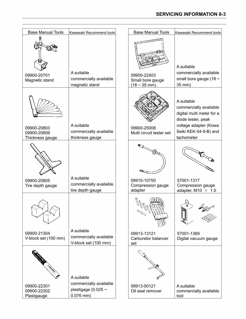
SERVICING INFORMATION 8-3
Base Manual Tools Kawasaki Recommend tools
09900-20701 Magnetic stand
A suitable commercially available magnetic stand
09900-20803 09900-20806 Thickness gauge
A suitable commercially available thickness gauge
09900-20805 Tire depth gauge
A suitable commercially available tire depth gauge
09900-21304 V-block set (100 mm)
A suitable commercially available V-block set (100 mm)
09900-22301 09900-22302 Plastigauge
A suitable commercially available plastigage (0.025 ~ 0.076 mm)
Base Manual Tools Kawasaki Recommend tools
09900-22403 Small bore gauge (18 ~ 35 mm)
A suitable commercially available small bore gauge (18 ~ 35 mm)
09900-25008 Multi circuit tester set
A suitable commercially available digital multi meter for a diode tester, peak voltage adapter (Kowa Seiki KEK-54-9-B) and tachometer
09910-10750 Compression gauge adapter
57001-1317 Compression gauge adapter, M10 1.0
09913-13121 Carburetor balancer set
57001-1369 Digital vacuum gauge
09913-50121 Oil seal remover
A suitable commercially available tool

SERVICING INFORMATION 8-4
Base Manual Tools Kawasaki Recommend tools
09913-60230 Journal bearing remover/installer
57001-S065 Journal bearing remover/installer
09913-60240 Journal bearing holder
57001-S066 Journal bearing holder
09913-70210 Bearing installer set
57001-1129 Bearing driver set
09915-40610 Oil filter wrench
57001-S067 Oil filter wrench
09915-64510 Compression gauge set
57001-221 Compression gauge, 20 kgf/cm2
Base Manual Tools Kawasaki Recommend tools
09915-72410 Oil pressure gauge attachment
57001-S068 Oil pressure gauge attachment
09915-74521 Oil pressure gauge hose
57001-S058 Oil pressure gauge hose
09915-74532 Oil pressure gauge adapter
57001-S069 Oil pressure gauge adapter
09915-77331 Meter (for high pressure)
57001-164 Oil pressure gauge, 10 kgf/cm2
09916-10911 Valve lapper set
A suitable commercially available valve lapper
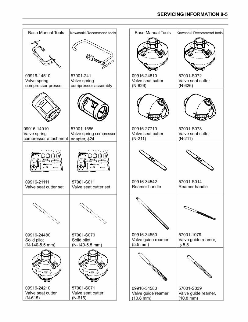
SERVICING INFORMATION 8-5
Base Manual Tools Kawasaki Recommend tools
09916-14510 Valve spring compressor presser
57001-241 Valve spring compressor assembly
09916-14910 Valve spring compressor attachment
57001-1586 Valve spring compressor adapter, 24
09916-21111 Valve seat cutter set
57001-S011 Valve seat cutter set
09916-24480 Solid pilot (N-140-5.5 mm)
57001-S070 Solid pilot (N-140-5.5 mm)
09916-24210 Valve seat cutter (N-615)
57001-S071 Valve seat cutter (N-615)
Base Manual Tools Kawasaki Recommend tools
09916-24810 Valve seat cutter (N-626)
57001-S072 Valve seat cutter (N-626)
09916-27710 Valve seat cutter (N-211)
57001-S073 Valve seat cutter (N-211)
09916-34542 Reamer handle
57001-S014 Reamer handle
09916-34550 Valve guide reamer (5.5 mm)
57001-1079 Valve guide reamer,
5.5
09916-34580 Valve guide reamer (10.8 mm)
57001-S039 Valve guide reamer, (10.8 mm)

SERVICING INFORMATION 8-6
Base Manual Tools Kawasaki Recommend tools
09916-44910 Valve guide remover/installer
57001-1021 Valve guide arbor,
5.5
09916-53340 Attachment
57001-S074 Attachment
09916-84511 Tweezers
A suitable commercially available tweezers
09917-47010 Vacuum pump gauge
A suitable commerciallyavailable tool
09920-13120 Crankcase separating tool
57001-1362 Crankcase splitting tool assembly
Base Manual Tools Kawasaki Recommend tools
09920-53740 Clutch sleeve hub holder
57001-1243 Clutch holder
09921-20240 Bearing remover set
57001-1058 Oil seal & bearing remover
09922-22711 Drive chain cutting and joining tool
A suitable commercially available tool
09923-73210 Bearing remover
57001-S037 Bearing Remover, 17 Max.
09923-74511 Bearing puller
57001-1058 Oil seal & bearing remover

SERVICING INFORMATION 8-7
Base Manual Tools Kawasaki Recommend tools
09924-74570 Final drive gear bearing installer/remover
57001-S075 Final drive gear bearing installer/remover
09924-84510 Bearing installer set
57001-S044 Bearing Installer Set
09924-84521 Bearing installer set
57001-S023 Bearing Installer Set
09925-18011 Steering bearing installer
57001-137 Steering Stem Bearing Driver
09930-11920 Torx bit JT40H
A suitable commerciallyavailable tool
Base Manual Tools Kawasaki Recommend tools
09930-11940 Bit holder
A suitable commerciallyavailable tool
09930-11950 Torx wrench
A suitable commerciallyavailable tool
09930-30102 Sliding shaft
57001-1058 Oil seal & bearing remover
09930-30450 Rotor remover
57001-S076 Rotor remover
09930-44541 Rotor holder
57001-S077 Rotor holder
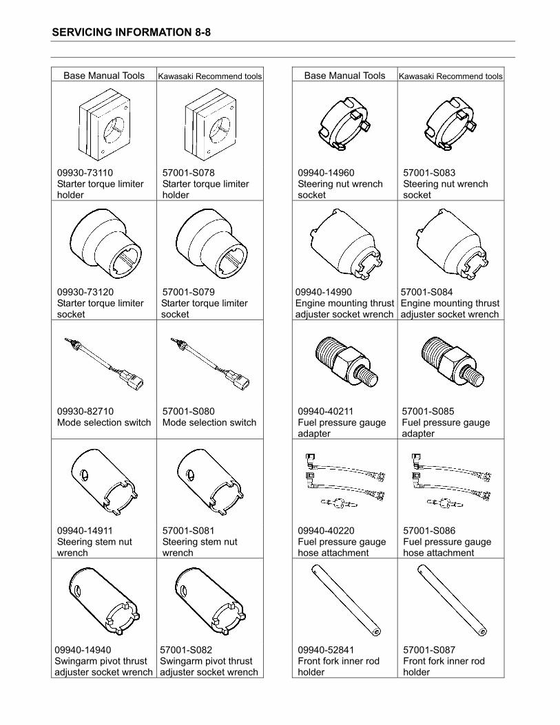
SERVICING INFORMATION 8-8
Base Manual Tools Kawasaki Recommend tools
09930-73110 Starter torque limiter holder
57001-S078 Starter torque limiter holder
09930-73120 Starter torque limiter socket
57001-S079 Starter torque limiter socket
09930-82710 Mode selection switch
57001-S080 Mode selection switch
09940-14911 Steering stem nut wrench
57001-S081 Steering stem nut wrench
09940-14940 Swingarm pivot thrust adjuster socket wrench
57001-S082 Swingarm pivot thrust adjuster socket wrench
Base Manual Tools Kawasaki Recommend tools
09940-14960 Steering nut wrench socket
57001-S083 Steering nut wrench socket
09940-14990 Engine mounting thrust adjuster socket wrench
57001-S084 Engine mounting thrust adjuster socket wrench
09940-40211 Fuel pressure gauge adapter
57001-S085 Fuel pressure gauge adapter
09940-40220 Fuel pressure gauge hose attachment
57001-S086 Fuel pressure gauge hose attachment
09940-52841 Front fork inner rod holder
57001-S087 Front fork inner rod holder

SERVICING INFORMATION 8-9
Base Manual Tools Kawasaki Recommend tools
09940-52861 Front fork oil seal installer set
57001-S034 Front fork oil seal installer set
099340-92720 Spring scale
A suitable commercially available spring scale
09941-34513 Steering race installer
57001-1129 Bearing driver set
Base Manual Tools Kawasaki Recommend tools
09941-54911 Bearing outer race remover
57001-1107 Head pipe outer race remover
09943-74111 Fork oil level gauge
57001-1290 Fork oil level gauge
09944-28320 HEXAGON BIT
A suitable commerciallyavailable tool, Hex 19
NOTEWhen ordering a special tool, please confirm whether it is available or not.

SERVICING INFORMATION 8-10

EMISSION CONTROL INFORMATION 9-1
Emission Control Information
Contents
EMISSION CONTROL SYSTEMS ................................................................................ Base Manual
FUEL INJECTION SYSTEM ...................................................................................... Base Manual
CRANKCASE EMISSION CONTROL SYSTEM........................................................ Base Manual
EXHAUST EMISSION CONTROL SYSTEM (PAIR SYSTEM) .................................. Base Manual
NOISE EMISSION CONTROL SYSTEM ................................................................... Base Manual
EVAPORATIVE EMISSION CONTROL SYSTEM (Only for E-33)............................. Base Manual
PAIR (AIR SUPPLY) SYSTEM INSPECTION ............................................................... Base Manual
PAIR (AIR SUPPLY) SYSTEM HOSE ROUTING.......................................................... Base Manual
HEATED OXGEN SENSOR (HO2S) INSPECTION....................................................... Base Manual
HEATED OXGEN SENSOR WIRE ROUTING .............................................................. Base Manual
EVAPORATIVE EMISSION CONTROL SYSTEM INSPECTION (Only for E-33) ......... Base Manual
CANISTER HOSE ROUTING (Only for E-33) ............................................................... Base Manual

EMISSION CONTROL INFORMATION 9-2
Base Manual
Suzuki DL1000
Note: Use the Kawasaki Service Manual Supplement along with the Suzuki Base Manual when servicing the Kawasaki KLV1000-A1 models.


GROUP INDEX
GENERAL INFORMATION 1
PERIODIC MAINTENANCE 2
ENGINE 3
FI SYSTEM 4
COOLING AND LUBRICATION SYSTEM 5
CHASSIS 6
ELECTRICAL SYSTEM 7
SERVICING INFORMATION 8
EMISSION CONTROL INFORMATION 9
DL1000K3 (’03-MODEL) 10
DL1000K4 (’04-MODEL) 11
WIRING DIAGRAM 12
© COPYRIGHT SUZUKI MOTOR CORPORATION 2002
FOREWORDThis manual contains an introductory description onthe SUZUKI DL1000 and procedures for its inspec-tion/service and overhaul of its main components.Other information considered as generally known isnot included.Read the GENERAL INFORMATION section tofamiliarize yourself with the motorcycle and its main-tenance. Use this section as well as other sectionsto use as a guide for proper inspection and service.This manual will help you know the motorcycle bet-ter so that you can assure your customers of fastand reliable service.
* This manual has been prepared on the basisof the latest specifications at the time of publi-cation. If modifications have been made sincethen, differences may exist between the con-tent of this manual and the actual motorcycle.
* Illustrations in this manual are used to showthe basic principles of operation and workprocedures. They may not represent theactual motorcycle exactly in detail.
* This manual is written for persons who haveenough knowledge, skills and tools, includingspecial tools, for servicing SUZUKI motorcy-cles. If you do not have the proper knowledgeand tools, ask your authorized SUZUKImotorcycle dealer to help you.
Inexperienced mechanics or mechanicswithout the proper tools and equipmentmay not be able to properly perform theservices described in this manual.Improper repair may result in injury to themechanic and may render the motorcycleunsafe for the rider and passenger.

HOW TO USE THIS MANUALTO LOCATE WHAT YOU ARE LOOKING FOR:1. The text of this manual is divided into sections.2. The section titles are listed in the GROUP INDEX.3. Holding the manual as shown at the right will allow you to find
the first page of the section easily.4. The contents are listed on the first page of each section to
help you find the item and page you need.
COMPONENT PARTS AND WORK TO BE DONEUnder the name of each system or unit, is its exploded view. Work instructions and other service informationsuch as the tightening torque, lubricating points and locking agent points, are provided.
Example: Front wheel
ITEM N·m kgf-m lb-ft
100 10.0 72.5
23 2.3 16.5
Brake disc Dust seal Bearing Center spacer Coller Front wheel Tire valve
Front axle Brake disc bolt
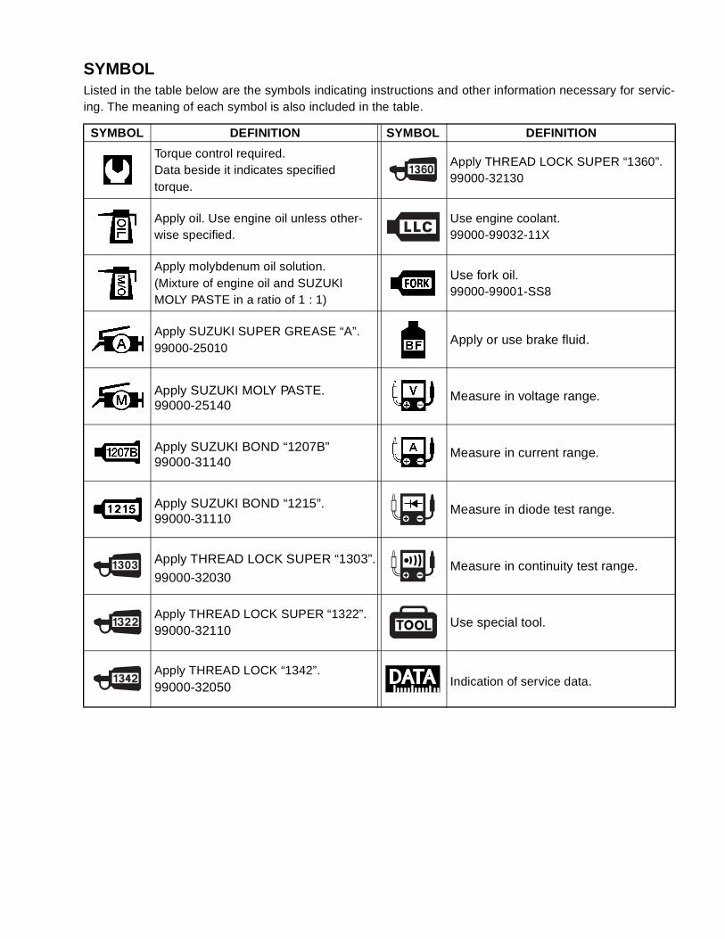
SYMBOLListed in the table below are the symbols indicating instructions and other information necessary for servic-ing. The meaning of each symbol is also included in the table.
SYMBOL DEFINITION SYMBOL DEFINITION
Torque control required.Data beside it indicates specified torque.
Apply THREAD LOCK SUPER “1360”.99000-32130
Apply oil. Use engine oil unless other-wise specified.
Use engine coolant.99000-99032-11X
Apply molybdenum oil solution.(Mixture of engine oil and SUZUKl MOLY PASTE in a ratio of 1 : 1)
Use fork oil.99000-99001-SS8
Apply SUZUKI SUPER GREASE “A”.99000-25010
Apply or use brake fluid.
Apply SUZUKI MOLY PASTE.99000-25140
Measure in voltage range.
Apply SUZUKI BOND “1207B”99000-31140
Measure in current range.
Apply SUZUKI BOND “1215”.99000-31110
Measure in diode test range.
Apply THREAD LOCK SUPER “1303”.
99000-32030Measure in continuity test range.
Apply THREAD LOCK SUPER “1322”.99000-32110
Use special tool.
Apply THREAD LOCK “1342”.99000-32050 Indication of service data.

ABBREVIATIONS USED IN THIS MANUALA
ABDC : After Bottom Dead CenterAC : Alternating CurrentACL : Air Cleaner, Air Cleaner BoxAPI : American Petroleum InstituteATDC : After Top Dead CenterATM Pressure: Atmospheric Pressure
Atmospheric Pressure Sensor (APS)
A/F : Air Fuel Mixture
BBBDC : Before Bottom Dead CenterBTDC : Before Top Dead CenterB+ : Battery Positive Voltage
CCKP Sensor : Crankshaft Position Sensor
(CKPS)CKT : CircuitCLP Switch : Clutch Lever Position Switch
(Clutch Switch)CMP Sensor : Camshaft Position Sensor
(CMPS)CO : Carbon MonoxideCPU : Central Processing Unit
DDC : Direct CurrentDMC : Dealer Mode CouplerDOHC : Double Over Head CamshaftDRL : Daytime Running Light
EECM : Engine Control Module
Engine Control Unit (ECU)(FI Control Unit)
ECT Sensor : Engine Coolant TemperatureSensor (ECTS), Water Temp.Sensor (WTS)
EVAP : Evaporative EmissionEVAP Canister : Evaporative Emission
Canister (Canister)
FFI : Fuel Injection, Fuel InjectorFP : Fuel PumpFPR : Fuel Pressure RegulatorFP Relay : Fuel Pump Relay
GGEN : GeneratorGND : GroundGP Switch : Gear Position Switch
HHC : Hydrocarbons
IIAP Sensor : Intake Air Pressure Sensor (IAPS)IAT Sensor : Intake Air Temperature Sensor
(IATS)IG : Ignition
LLCD : Liquid Crystal DisplayLED : Light Emitting Diode
(Malfunction Indicator Lamp)LH : Left Hand
MMAL-Code : Malfunction Code
(Diagnostic Code)Max : MaximumMIL : Malfunction Indicator Lamp
(LED)Min : Minimum
NNOx : Nitrogen Oxides
OOHC : Over Head CamshaftOPS : Oil Pressure Switch
PPCV : Positive Crankcase
Ventilation (Crankcase Breather)
RRH : Right HandROM : Read Only Memory
SSAE : Society of Automotive EngineersSTC System : Secondary Throttle Control
System (STCS)STP Sensor : Secondary Throttle Position
Sensor (STPS)ST Valve : Secondary Throttle Valve (STV)STV Actuator : Secondary Throttle Valve Actuator
(STVA)
TTO Sensor : Tip Over Sensor (TOS)TP Sensor : Throttle Position Sensor (TPS)
VVD : Vacuum Damper

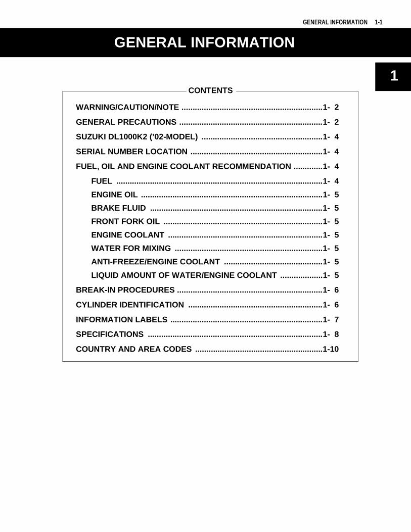
1
GENERAL INFORMATION 1-1
CONTENTS
GENERAL INFORMATION
WARNING/CAUTION/NOTE ...............................................................1- 2
GENERAL PRECAUTIONS ................................................................1- 2
SUZUKI DL1000K2 (’02-MODEL) ......................................................1- 4
SERIAL NUMBER LOCATION ...........................................................1- 4
FUEL, OIL AND ENGINE COOLANT RECOMMENDATION .............1- 4
FUEL ............................................................................................1- 4
ENGINE OIL .................................................................................1- 5
BRAKE FLUID .............................................................................1- 5
FRONT FORK OIL .......................................................................1- 5
ENGINE COOLANT .....................................................................1- 5
WATER FOR MIXING ..................................................................1- 5
ANTI-FREEZE/ENGINE COOLANT ............................................1- 5
LIQUID AMOUNT OF WATER/ENGINE COOLANT ...................1- 5
BREAK-lN PROCEDURES .................................................................1- 6
CYLINDER IDENTIFICATION ............................................................1- 6
INFORMATION LABELS ....................................................................1- 7
SPECIFICATIONS ..............................................................................1- 8
COUNTRY AND AREA CODES .........................................................1-10
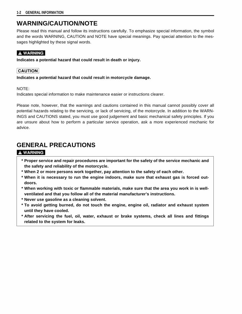
1-2 GENERAL INFORMATION
WARNING/CAUTION/NOTEPlease read this manual and follow its instructions carefully. To emphasize special information, the symboland the words WARNING, CAUTION and NOTE have special meanings. Pay special attention to the mes-sages highlighted by these signal words.
Indicates a potential hazard that could result in death or injury.
Indicates a potential hazard that could result in motorcycle damage.
NOTE:Indicates special information to make maintenance easier or instructions clearer.
Please note, however, that the warnings and cautions contained in this manual cannot possibly cover allpotential hazards relating to the servicing, or lack of servicing, of the motorcycle. In addition to the WARN-INGS and CAUTIONS stated, you must use good judgement and basic mechanical safety principles. If youare unsure about how to perform a particular service operation, ask a more experienced mechanic foradvice.
GENERAL PRECAUTIONS
* Proper service and repair procedures are important for the safety of the service mechanic andthe safety and reliability of the motorcycle.
* When 2 or more persons work together, pay attention to the safety of each other.* When it is necessary to run the engine indoors, make sure that exhaust gas is forced out-
doors.* When working with toxic or flammable materials, make sure that the area you work in is well-
ventilated and that you follow all of the material manufacturer’s instructions.* Never use gasoline as a cleaning solvent.* To avoid getting burned, do not touch the engine, engine oil, radiator and exhaust system
until they have cooled.* After servicing the fuel, oil, water, exhaust or brake systems, check all lines and fittings
related to the system for leaks.
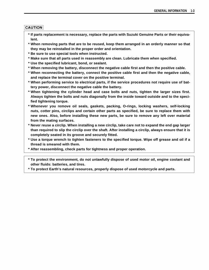
GENERAL INFORMATION 1-3
* If parts replacement is necessary, replace the parts with Suzuki Genuine Parts or their equiva-lent.
* When removing parts that are to be reused, keep them arranged in an orderly manner so thatthey may be reinstalled in the proper order and orientation.
* Be sure to use special tools when instructed.* Make sure that all parts used in reassembly are clean. Lubricate them when specified.* Use the specified lubricant, bond, or sealant.* When removing the battery, disconnect the negative cable first and then the positive cable.* When reconnecting the battery, connect the positive cable first and then the negative cable,
and replace the terminal cover on the positive terminal.* When performing service to electrical parts, if the service procedures not require use of bat-
tery power, disconnect the negative cable the battery.* When tightening the cylinder head and case bolts and nuts, tighten the larger sizes first.
Always tighten the bolts and nuts diagonally from the inside toward outside and to the speci-fied tightening torque.
* Whenever you remove oil seals, gaskets, packing, O-rings, locking washers, self-lockingnuts, cotter pins, circlips and certain other parts as specified, be sure to replace them withnew ones. Also, before installing these new parts, be sure to remove any left over materialfrom the mating surfaces.
* Never reuse a circlip. When installing a new circlip, take care not to expand the end gap largerthan required to slip the circlip over the shaft. After installing a circlip, always ensure that it iscompletely seated in its groove and securely fitted.
* Use a torque wrench to tighten fasteners to the specified torque. Wipe off grease and oil if athread is smeared with them.
* After reassembling, check parts for tightness and proper operation.
* To protect the environment, do not unlawfully dispose of used motor oil, engine coolant andother fluids: batteries, and tires.
* To protect Earth’s natural resources, properly dispose of used motorcycle and parts.
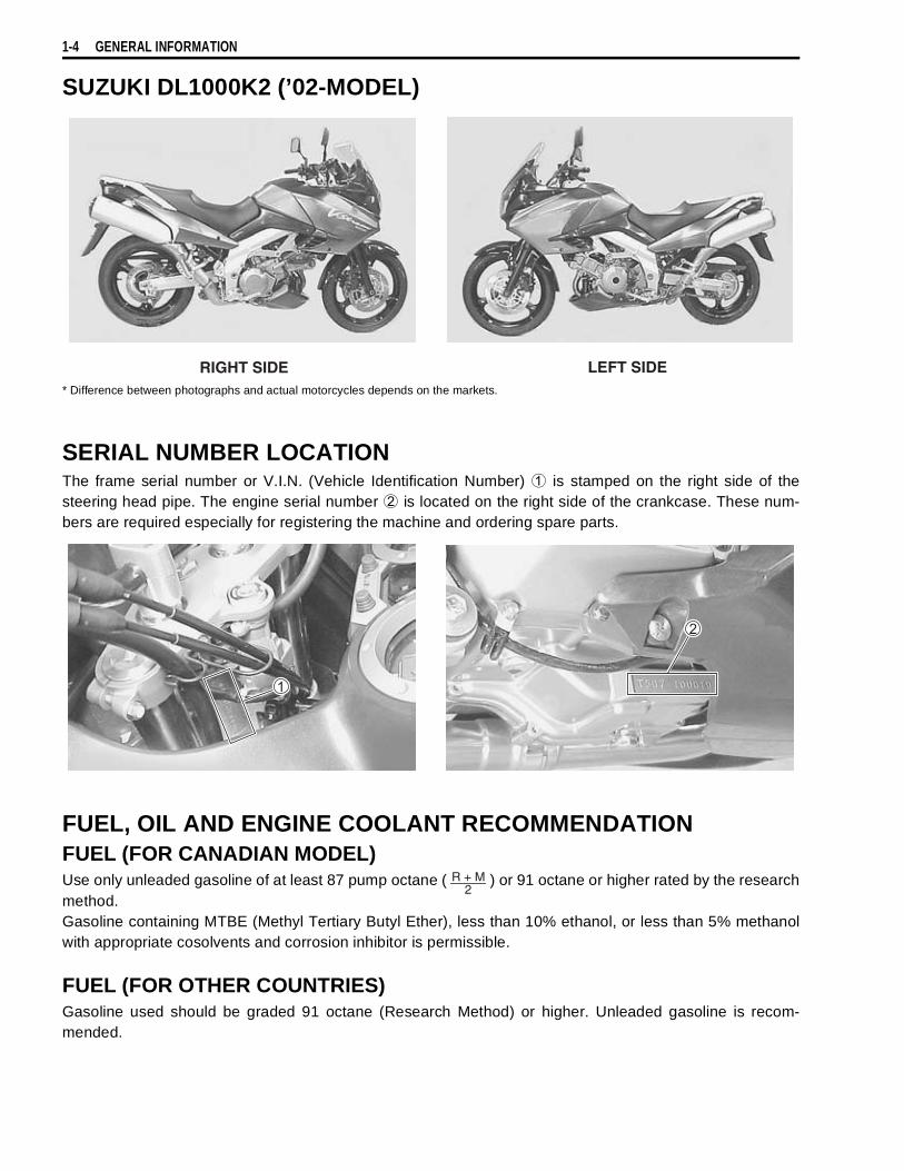
1-4 GENERAL INFORMATION
SUZUKI DL1000K2 (’02-MODEL)
* Difference between photographs and actual motorcycles depends on the markets.
SERIAL NUMBER LOCATIONThe frame serial number or V.I.N. (Vehicle Identification Number)
is stamped on the right side of thesteering head pipe. The engine serial number
is located on the right side of the crankcase. These num-bers are required especially for registering the machine and ordering spare parts.
FUEL, OIL AND ENGINE COOLANT RECOMMENDATIONFUEL (FOR CANADIAN MODEL)Use only unleaded gasoline of at least 87 pump octane ( ) or 91 octane or higher rated by the researchmethod.Gasoline containing MTBE (Methyl Tertiary Butyl Ether), less than 10% ethanol, or less than 5% methanolwith appropriate cosolvents and corrosion inhibitor is permissible.
FUEL (FOR OTHER COUNTRIES)Gasoline used should be graded 91 octane (Research Method) or higher. Unleaded gasoline is recom-mended.
RIGHT SIDE LEFT SIDE
2R + M
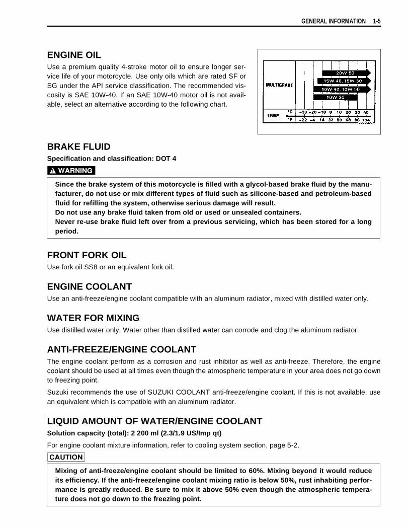
GENERAL INFORMATION 1-5
ENGINE OILUse a premium quality 4-stroke motor oil to ensure longer ser-vice life of your motorcycle. Use only oils which are rated SF orSG under the API service classification. The recommended vis-cosity is SAE 10W-40. If an SAE 10W-40 motor oil is not avail-able, select an alternative according to the following chart.
BRAKE FLUIDSpecification and classification: DOT 4
FRONT FORK OILUse fork oil SS8 or an equivalent fork oil.
ENGINE COOLANTUse an anti-freeze/engine coolant compatible with an aluminum radiator, mixed with distilled water only.
WATER FOR MIXINGUse distilled water only. Water other than distilled water can corrode and clog the aluminum radiator.
ANTI-FREEZE/ENGINE COOLANTThe engine coolant perform as a corrosion and rust inhibitor as well as anti-freeze. Therefore, the enginecoolant should be used at all times even though the atmospheric temperature in your area does not go downto freezing point.
Suzuki recommends the use of SUZUKI COOLANT anti-freeze/engine coolant. If this is not available, usean equivalent which is compatible with an aluminum radiator.
LIQUID AMOUNT OF WATER/ENGINE COOLANTSolution capacity (total): 2 200 ml (2.3/1.9 US/Imp qt)
For engine coolant mixture information, refer to cooling system section, page 5-2.
Since the brake system of this motorcycle is filled with a glycol-based brake fluid by the manu-facturer, do not use or mix different types of fluid such as silicone-based and petroleum-basedfluid for refilling the system, otherwise serious damage will result.Do not use any brake fluid taken from old or used or unsealed containers.Never re-use brake fluid left over from a previous servicing, which has been stored for a longperiod.
Mixing of anti-freeze/engine coolant should be limited to 60%. Mixing beyond it would reduceits efficiency. If the anti-freeze/engine coolant mixing ratio is below 50%, rust inhabiting perfor-mance is greatly reduced. Be sure to mix it above 50% even though the atmospheric tempera-ture does not go down to the freezing point.

1-6 GENERAL INFORMATION
BREAK-lN PROCEDURESDuring manufacture only the best possible materials are used and all machined parts are finished to a veryhigh standard but it is still necessary to allow the moving parts to “BREAK-IN” before subjecting the engineto maximum stresses. The future performance and reliability of the engine depends on the care and restraintexercised during its early life. The general rules are as follows.
• Keep to these break-in engine speed limits:
Initial 800 km ( 500 miles): Below 4 500 r/minUp to 1 600 km (1 000 miles): Below 7 000 r/minOver 1 600 km (1 000 miles): Below 9 500 r/min
• Upon reaching an odometer reading of 1 600 km (1 000 miles) you can subject the motorcycle to full throt-tle operation. However, do not exceed 9 500 r/min at any time.
CYLINDER IDENTIFICATIONThe two cylinders of this engine are identified as No.1 and No.2 cylinder, as counted from front to rear (asviewed by the rider on the seat).
#1
#2

GENERAL INFORMATION 1-7
INFORMATION LABELS
Noise label (For E-03, 24, 33) Information label (For E-03, 28, 33) ICES Canada label (For E-28) Vacuum hose routing label (For E-33) Fuel caution label (For E-02, 24) Manual notice label (For E-03, 33) Tire pressure label Warning safety label Rear carrier warning label Frame caution label Steering warning label Screen warning label ID label (For E-02, 19, 24) Safety label (For E-03, 28, 33)
For E-28 (French)
For E-28
These labels are attachedon the right frame.
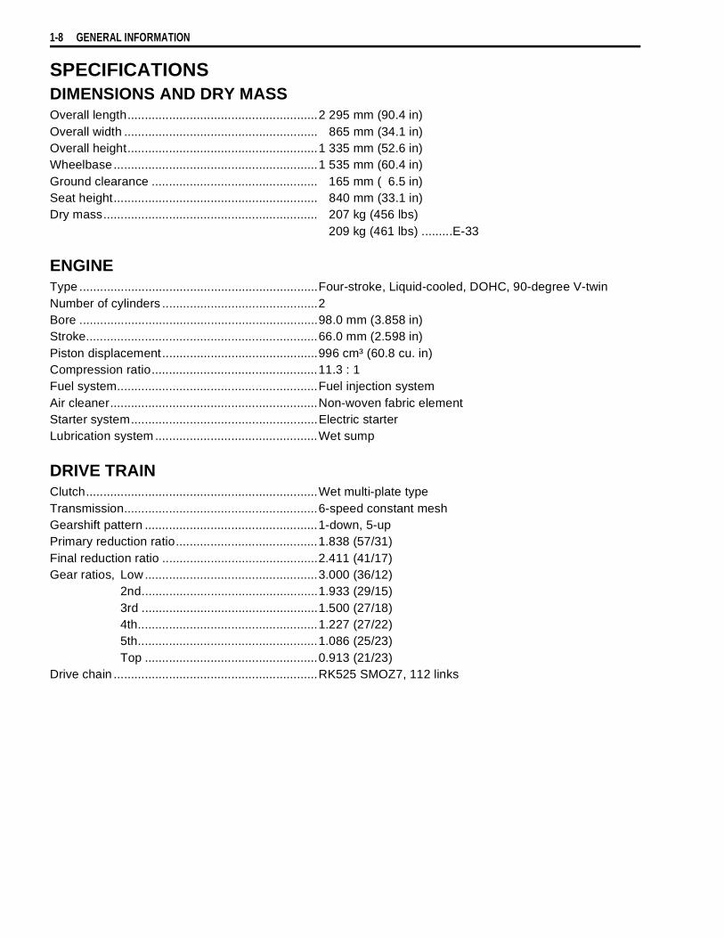
1-8 GENERAL INFORMATION
SPECIFICATIONSDIMENSIONS AND DRY MASSOverall length.......................................................2 295 mm (90.4 in)Overall width ........................................................ 865 mm (34.1 in)Overall height.......................................................1 335 mm (52.6 in)Wheelbase...........................................................1 535 mm (60.4 in)Ground clearance ................................................ 165 mm ( 6.5 in)Seat height........................................................... 840 mm (33.1 in)Dry mass.............................................................. 207 kg (456 lbs)
209 kg (461 lbs) .........E-33
ENGINEType .....................................................................Four-stroke, Liquid-cooled, DOHC, 90-degree V-twinNumber of cylinders .............................................2Bore .....................................................................98.0 mm (3.858 in)Stroke...................................................................66.0 mm (2.598 in)Piston displacement.............................................996 cm³ (60.8 cu. in)Compression ratio................................................11.3 : 1Fuel system..........................................................Fuel injection systemAir cleaner............................................................Non-woven fabric elementStarter system......................................................Electric starterLubrication system ...............................................Wet sump
DRIVE TRAINClutch...................................................................Wet multi-plate typeTransmission........................................................6-speed constant meshGearshift pattern ..................................................1-down, 5-upPrimary reduction ratio.........................................1.838 (57/31)Final reduction ratio .............................................2.411 (41/17)Gear ratios, Low ..................................................3.000 (36/12)
2nd...................................................1.933 (29/15)3rd ...................................................1.500 (27/18)4th....................................................1.227 (27/22)5th....................................................1.086 (25/23)Top ..................................................0.913 (21/23)
Drive chain ...........................................................RK525 SMOZ7, 112 links

GENERAL INFORMATION 1-9
CHASSISFront suspension................................................. Inverted telescopic, coil spring, oil dampedRear suspension ................................................. Link type, coil spring, oil dampedSteering angle ..................................................... 40° (right & left)Caster.................................................................. 26° 30’Trail ..................................................................... 111 mm (4.3 in)Turning radius ..................................................... 2.7 m (8.86 ft)Front brake.......................................................... Disc brake, twinRear brake .......................................................... Disc brakeFront tire size ...................................................... 110/80 R19M/C 59H, tubelessRear tire size ....................................................... 150/70 R17M/C 69H, tubelessFront fork stroke .................................................. 160 mm (6.3 in)Rear wheel travel ................................................ 159 mm (6.2 in)
ELECTRICAL lgnition type ......................................................... Electronic ignition (ECM, Transistorized)lgnition timing ...................................................... 4° B. T. D. C at 1 200 r/minSpark plug ........................................................... NGK: CR8EK or DENSO: U24ETRBattery................................................................. 12 V 43.2 kC (12 Ah)/10 HRGenerator ............................................................ Three-phase A.C. GeneratorFuse .................................................................... 30/15/15/15/15/15/10 AHeadlight ............................................................. 12 V 60/55 W H4Position light........................................................ 12 V 5 W × 2.........Except for E-03, 24, 28, 33Turn signal light................................................... 12 V 10 WLicense light ........................................................ 12 V 5 WBrake light/Taillight .............................................. 12 V 21/5 W ×2Speedometer/Tachometer light........................... LEDNeutral indicator light .......................................... LEDHigh beam indicator light..................................... LEDTurn signal indicator light .................................... LEDOver drive indicator light ..................................... LEDFuel injector warning light ................................... LEDEngine coolant temperature warning light........... LEDOil pressure warning light.................................... LED
CAPACITIES Fuel tank ............................................................. 22 L (5.8/4.8 US/Imp gal)Engine oil, oil change ........................................ 2 700 ml (2.9/2.4 US/Imp qt)
with filter change.............................. 2 900 ml (3.1/2.6 US/Imp qt)overhaul ........................................... 3 300 ml (3.5/2.9 US/Imp qt)
Engine coolant, including reserve ....................... 2 200 ml (2.3/1.9 US/Imp oz)Front fork oil (each leg) ....................................... 505 ml (17.1/17.8 US/Imp oz)
These specifications are subject to change without notice.

1-10 GENERAL INFORMATION
COUNTRY AND AREA CODESThe following codes stand for the applicable country(-ies) and area(-s).
CODE COUNTRY or AREAE-02E-03E-19E-24E-28E-33
U. K.U. S. A. (Except for California)EUAustraliaCanadaCalifornia (U. S. A.)
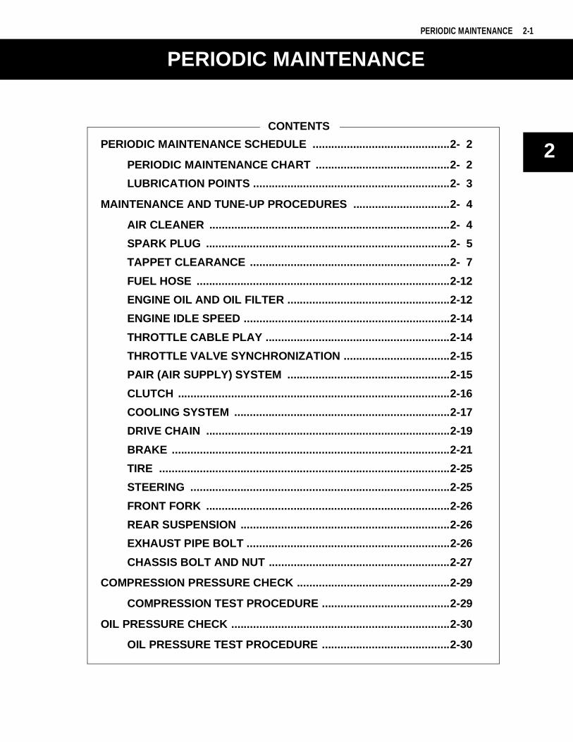
2
6
PERIODIC MAINTENANCE 2-1
CONTENTS
PERIODIC MAINTENANCE
PERIODIC MAINTENANCE SCHEDULE ............................................2- 2
PERIODIC MAINTENANCE CHART ...........................................2- 2
LUBRICATION POINTS ...............................................................2- 3
MAINTENANCE AND TUNE-UP PROCEDURES ...............................2- 4
AIR CLEANER .............................................................................2- 4
SPARK PLUG ..............................................................................2- 5
TAPPET CLEARANCE ................................................................2- 7
FUEL HOSE .................................................................................2-12
ENGINE OIL AND OIL FILTER ....................................................2-12
ENGINE IDLE SPEED ..................................................................2-14
THROTTLE CABLE PLAY ...........................................................2-14
THROTTLE VALVE SYNCHRONIZATION ..................................2-15
PAIR (AIR SUPPLY) SYSTEM ....................................................2-15
CLUTCH .......................................................................................2-16
COOLING SYSTEM .....................................................................2-17
DRIVE CHAIN ..............................................................................2-19
BRAKE .........................................................................................2-21
TIRE .............................................................................................2-25
STEERING ...................................................................................2-25
FRONT FORK ..............................................................................2-26
REAR SUSPENSION ...................................................................2-26
EXHAUST PIPE BOLT .................................................................2-26
CHASSIS BOLT AND NUT ..........................................................2-27
COMPRESSION PRESSURE CHECK .................................................2-29
COMPRESSION TEST PROCEDURE .........................................2-29
OIL PRESSURE CHECK ......................................................................2-30
OIL PRESSURE TEST PROCEDURE .........................................2-30

2-2 PERIODIC MAINTENANCE
PERIODIC MAINTENANCE SCHEDULEThe chart below lists the recommended intervals for all the required periodic service work necessary to keepthe motorcycle operating at peak performance and economy. Mileages are expressed in terms of kilome-ters, miles and time for your convenience.
NOTE:More frequent servicing may be performed on motorcycles that are used under severe conditions.
PERIODIC MAINTENANCE CHART
NOTE:I=Inspect and clean, adjust, replace or lubricate as necessary;R=Replace; T=Tighten
Interval
Item
km 1 000 6 000 12 000 18 000 24 000
miles 600 4 000 7 500 11 000 15 000
months 1 6 12 18 24Air cleaner element — I I R I
Exhaust pipe bolts and muffler bolts T — T — TValve clearance — — — — I
Spark plugs — I R I RFuel hose — I I I I
Replace every 4 yearsEngine oil R R R R R
Engine oil filter R — — R —Idle speed I I I I I
Throttle cable play I I I I IThrottle valve synchronization I — I — I
(E-33 only)Evaporative emission control system(E-33 only)
— — I — I
Replace vapor hose every 4 yearsPAIR(air supply)system — — I — I
Engine coolant Replace every 2 years.Radiator hose — I I I I
Clutch hose — I I I IReplace every 4 years
Clutch fluid — I I I IReplace every 2 years
Drive chain I I I I IClean and lublicate every 1 000 km (600 miles)
Brakes I I I I IBrake hose — I I I I
Replace every 4 yearsBrake fluid — I I I I
Replace every 2 yearsTires — I I I I
Steering I — I — IFront fork — — I — I
Rear suspension — — I — IChassis bolts and nuts T T T T T
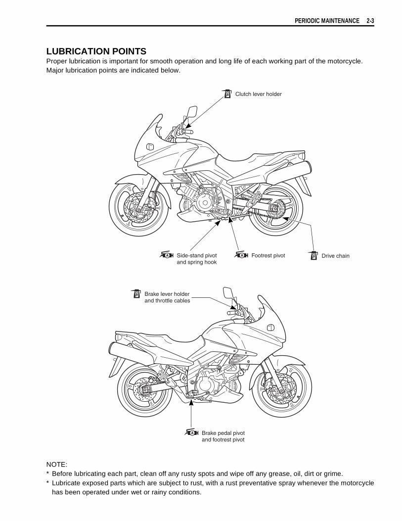
PERIODIC MAINTENANCE 2-3
LUBRICATION POINTSProper lubrication is important for smooth operation and long life of each working part of the motorcycle.Major lubrication points are indicated below.
NOTE:* Before lubricating each part, clean off any rusty spots and wipe off any grease, oil, dirt or grime.* Lubricate exposed parts which are subject to rust, with a rust preventative spray whenever the motorcycle
has been operated under wet or rainy conditions.
Clutch lever holder
Brake lever holderand throttle cables
Drive chainSide-stand pivot and spring hook
Brake pedal pivotand footrest pivot
Footrest pivot

2-4 PERIODIC MAINTENANCE
MAINTENANCE AND TUNE-UP PRO-CEDURESThis section describes the servicing procedures for each item ofthe Periodic Maintenance requirements.
AIR CLEANER
• Remove the seat. ( 6-4)• Remove the fuel tank. ( 4-52)• Remove the air cleaner box cap
.• Remove the air cleaner element
.
• Carefully use air hose to blow the dust from the cleaner ele-ment.
• Install the O-ring
properly.• Reinstall the cleaned or new air cleaner element in the
reverse order of removal.
Inspect every 6 000 km (4 000 miles, 6 months) andreplace every 18 000 km (11 000 miles, 18 months).
Always use air pressure on the throttle body side ofthe air cleaner element. If air pressure is used on theother side, dirt will be forced into the pores of the aircleaner element thus restricting air flow through theair cleaner element.
If driving under dusty condition, clean the air cleanerelement more frequently. The surest way to accelerateengine wear is to use the engine without the elementor to use a ruptured element. Make sure that the aircleaner is in good condition at all times. Life of theengine depends largely on this component!
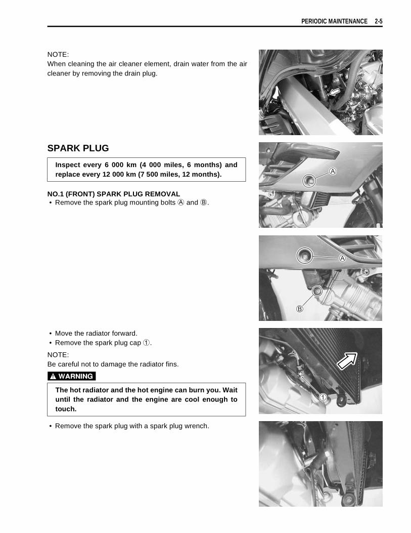
PERIODIC MAINTENANCE 2-5
NOTE:When cleaning the air cleaner element, drain water from the aircleaner by removing the drain plug.
SPARK PLUG
NO.1 (FRONT) SPARK PLUG REMOVAL• Remove the spark plug mounting bolts
and
.
• Move the radiator forward.• Remove the spark plug cap
.
NOTE:Be careful not to damage the radiator fins.
• Remove the spark plug with a spark plug wrench.
Inspect every 6 000 km (4 000 miles, 6 months) andreplace every 12 000 km (7 500 miles, 12 months).
The hot radiator and the hot engine can burn you. Waituntil the radiator and the engine are cool enough totouch.

2-6 PERIODIC MAINTENANCE
NO.2 (REAR) SPARK PLUG REMOVAL• Remove the seat. ( 6-4)• Lift and support the fuel tank. ( 4-51)• Remove the spark plug cap.• Remove the spark plug with a spark plug wrench.
HEAT RANGE• Check to see the heat range of the plug.
CARBON DEPOSIT• Check to see if there are carbons deposit on the plugs. If car-
bon is deposited, remove it with a spark plug cleaner machineor carefully using a tool with a pointed end.
SPARK PLUG GAP• Measure the plug gap with a thickness gauge. If out of specifi-
cation, adjust it to the following gap.
09900-20803: Thickness gauge
Spark plug gap
Standard: 0.6 – 0.7 mm (0.024 – 0.028 in)
ELECTRODES CONDITION• Check to see the worn or burnt condition of the electrodes. If it
is extremely worn or burnt, replace the plug. And also replacethe plug if it has a broken insulator, damaged thread.
Standard Cold type
NGK CR8EK CR9EK or CR10EKDENSO U24ETR U27ETR or U31ETR
Confirm the thread size and reach when replacing theplug. If the reach is too short, carbon will be depositedon the screw portion of the plug hole and engine dam-age may result.
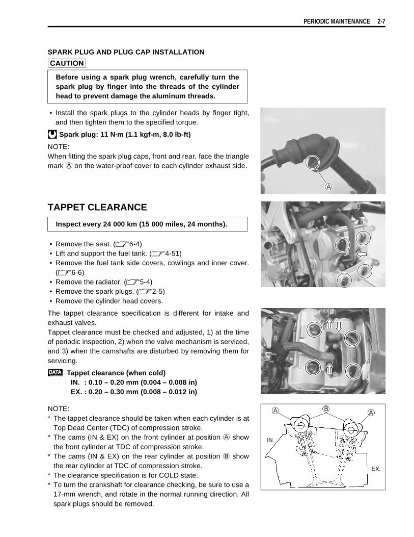
PERIODIC MAINTENANCE 2-7
SPARK PLUG AND PLUG CAP INSTALLATION
• Install the spark plugs to the cylinder heads by finger tight,and then tighten them to the specified torque.
Spark plug: 11 N·m (1.1 kgf-m, 8.0 lb-ft)
NOTE:When fitting the spark plug caps, front and rear, face the trianglemark
on the water-proof cover to each cylinder exhaust side.
TAPPET CLEARANCE
• Remove the seat. ( 6-4)• Lift and support the fuel tank. ( 4-51)• Remove the fuel tank side covers, cowlings and inner cover.
( 6-6)• Remove the radiator. ( 5-4)• Remove the spark plugs. ( 2-5)• Remove the cylinder head covers.
The tappet clearance specification is different for intake andexhaust valves.Tappet clearance must be checked and adjusted, 1) at the timeof periodic inspection, 2) when the valve mechanism is serviced,and 3) when the camshafts are disturbed by removing them forservicing.
Tappet clearance (when cold)IN. : 0.10 – 0.20 mm (0.004 – 0.008 in)EX. : 0.20 – 0.30 mm (0.008 – 0.012 in)
NOTE:* The tappet clearance should be taken when each cylinder is at
Top Dead Center (TDC) of compression stroke.* The cams (IN & EX) on the front cylinder at position
showthe front cylinder at TDC of compression stroke.
* The cams (IN & EX) on the rear cylinder at position
showthe rear cylinder at TDC of compression stroke.
* The clearance specification is for COLD state.* To turn the crankshaft for clearance checking, be sure to use a
17-mm wrench, and rotate in the normal running direction. Allspark plugs should be removed.
Before using a spark plug wrench, carefully turn thespark plug by finger into the threads of the cylinderhead to prevent damage the aluminum threads.
Inspect every 24 000 km (15 000 miles, 24 months).
EX.
IN.

2-8 PERIODIC MAINTENANCE
• Remove the generator cover plug
and timing inspectionplug
.
• Turn the crankshaft to set the No.1 (Front) cylinder at TDC ofcompression stroke. (Align the “F | T” line on the generatorrotor to the index mark of valve timing inspection hole andalso bring the camshafts to the position as shown in page2-7.)
• To inspect the No.1 (Front) cylinder tappet clearance, use athickness gauge between the tappet and the cam. If the clear-ance is out of specification, adjust it into the specified range.
09900-20803: Thickness gauge
• Turn the crankshaft 270 degrees (¾ turns) to set the No.2(Rear) cylinder at TDC of compression stroke. (Align the“R | T” line on the generator rotor to the index mark of valvetiming inspection hole and also bring the camshafts to theposition as shown in page 2-7.)
• Inspect the No.2 (Rear) cylinder tappet clearance as thesame manner of No.1 (Front) cylinder and adjust the clear-ance if necessary.
09900-20803: Thickness gauge
F T
RR TTR T
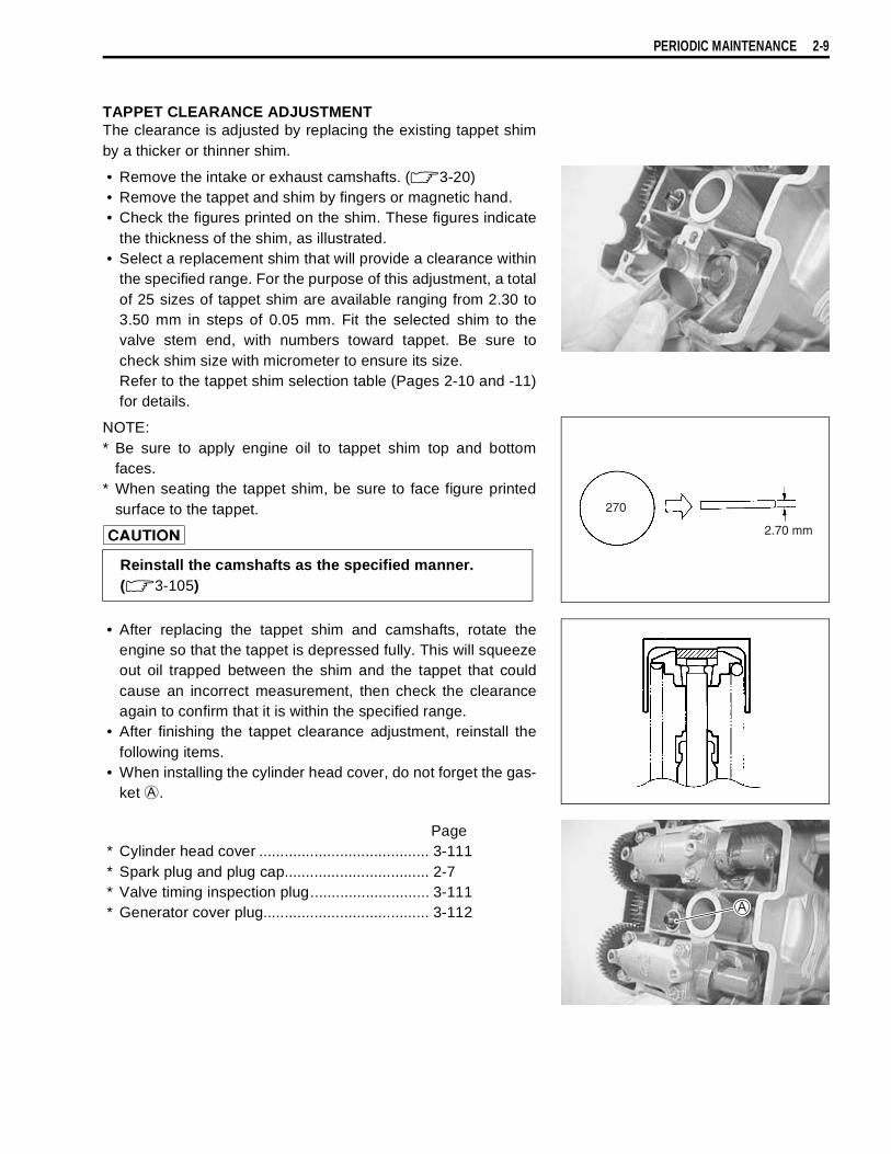
PERIODIC MAINTENANCE 2-9
TAPPET CLEARANCE ADJUSTMENTThe clearance is adjusted by replacing the existing tappet shimby a thicker or thinner shim.
• Remove the intake or exhaust camshafts. ( 3-20)• Remove the tappet and shim by fingers or magnetic hand.• Check the figures printed on the shim. These figures indicate
the thickness of the shim, as illustrated.• Select a replacement shim that will provide a clearance within
the specified range. For the purpose of this adjustment, a totalof 25 sizes of tappet shim are available ranging from 2.30 to3.50 mm in steps of 0.05 mm. Fit the selected shim to thevalve stem end, with numbers toward tappet. Be sure tocheck shim size with micrometer to ensure its size.Refer to the tappet shim selection table (Pages 2-10 and -11)for details.
NOTE:* Be sure to apply engine oil to tappet shim top and bottom
faces.* When seating the tappet shim, be sure to face figure printed
surface to the tappet.
• After replacing the tappet shim and camshafts, rotate theengine so that the tappet is depressed fully. This will squeezeout oil trapped between the shim and the tappet that couldcause an incorrect measurement, then check the clearanceagain to confirm that it is within the specified range.
• After finishing the tappet clearance adjustment, reinstall thefollowing items.
• When installing the cylinder head cover, do not forget the gas-ket
.
Page* Cylinder head cover ........................................ 3-111* Spark plug and plug cap.................................. 2-7* Valve timing inspection plug............................ 3-111* Generator cover plug....................................... 3-112
Reinstall the camshafts as the specified manner.( 3-105)
270
2.70 mm
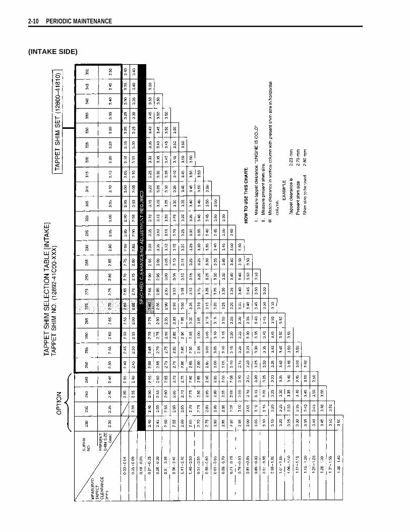
2-10 PERIODIC MAINTENANCE
(INTAKE SIDE)

PERIODIC MAINTENANCE 2-11
(EXHAUST SIDE)

2-12 PERIODIC MAINTENANCE
FUEL HOSE
Inspect the fuel feed hose
for damage and fuel leakage. Ifany defects are found, the fuel hoses must be replaced.
ENGINE OIL AND OIL FILTER
Oil should be changed while the engine is warm. Oil filterreplacement at the above intervals, should be done togetherwith the engine oil change.
ENGINE OIL REPLACEMENT• Keep the motorcycle upright.• Place an oil pan below the engine, and drain oil by removing
the drain plug
and filler cap
.
• Tighten the drain plug
to the specified torque, and pourfresh oil through the oil filler. The engine will hold about 2.7 L(2.9/2.4 US/Imp qt) of oil. Use an API classification of SF orSG oil with SAE 10W-40 viscosity.
Oil drain plug: 23 N·m (2.3 kg-m, 16.5 lb-ft)
Inspect every 6 000 km (4 000 miles, 6 months).Replace every 4 years.
(ENGINE OIL)Replace initially at 1 000 km (600 miles, 1 month) andevery 6 000 km (4 000 miles, 6 months) thereafter.
(OIL FILTER)Replace initially at 1 000 km (600 miles, 1 month) andevery 18 000 km (11 000 miles, 18 months) thereafter.

PERIODIC MAINTENANCE 2-13
• Start up the engine and allow it to run for several minutes atidling speed.
• Turn off the engine and wait about one minute, then check theoil level through the inspection window
. If the level is belowmark “L”, add oil to “F” level. If the level is above mark “F”,drain oil to “F” level.
OIL FILTER REPLACEMENT• Remove the engine under cover
.• Drain engine oil in the same manner of engine oil replacement
procedure.• Remove the oil filter
by using the oil filter wrench. (Specialtool)
• Apply engine oil lightly to the gasket of the new filter beforeinstallation.
• Install the new filter turning it by hand until you feel that the fil-ter gasket contacts the mounting surface. Then tighten it 2turns using the oil filter wrench.
09915-40610: Oil filter wrench
NOTE:To properly tighten the filter, use the special tool. Never tightenthe filter by hand.
• Pour fresh engine oil and check the oil level in the same man-ner of engine oil replacement procedure.
Engine oil capacity Oil change: 2.7 L (2.9/2.4 US/Imp qt)Filter change: 2.9 L (3.1/2.6 US/Imp qt)Overhaul engine: 3.3 L (3.5/2.9 US/Imp qt)
ONLY USE A GENUINE SUZUKI MOTORCYCLE OILFILTER. Other manufacturer’s oil filters may differ inthread specifications (thread diameter and pitch), fil-tering performance and durability which may lead toengine damage or oil leaks. Also, do not use a genuineSuzuki automobile oil filter on this motorcycle.
After contcting the gasket,tighten 2 turns.

2-14 PERIODIC MAINTENANCE
ENGINE IDLE SPEED
NOTE:Make this adjustment when the engine is hot.
• Start up the engine and set its idle speed to the specifiedrange by turning the throttle stop screw
.
Engine idle speed: 1 200 ± 100 r/min
THROTTLE CABLE PLAY
Adjust the throttle cable play
with the following three steps.
MINOR ADJUSTMENTFirst step:• Remove cable adjuster covers
.• Loosen the locknut
of the throttle returning cable
andturn in the adjuster
fully into the threads.
Second step:• Loosen the locknut
of the throttle pulling cable
.• Turn the adjuster
in or out until the throttle cable play
should be 2.0 – 4.0 mm (0.08 – 0.16 in) at the throttle grip.• Tighten the locknut
while holding the adjuster
.
Third step:• While holding the throttle grip at the fully closed position,
slowly turn out the adjuster
of the throttle returning cable
to feel resistance.• Tighten the locknut
while holding the adjuster
.
Throttle cable play
: 2.0 – 4.0 mm (0.08 – 0.16 in)
NOTE:Major adjustment can be made by the throttle body sideadjuster.
Inspect initially at 1 000 km (600 miles, 1 month) andevery 6 000 km (4 000 miles, 6 months) thereafter.
Inspect initially at 1 000 km (600 miles, 1 month) andevery 6 000 km (4 000 miles, 6 months) thereafter.
After the adjustment is completed, check that handle-bar movement does not raise the engine idle speedand that the throttle grip returns smoothly and auto-matically.

PERIODIC MAINTENANCE 2-15
MAJOR ADJUSTMENT• Remove the fuel tank. ( 4-52)• Remove the air cleanet box. ( 4-60)• Loosen the locknut
of the throttle returning cable.• Turn the returning cable adjuster
to obtain proper cableplay.
• Loosen the locknut
of the throttle pulling cable.• Turn the pulling cable adjuster
in or out until the throttlecable play
should be 2.0 – 4.0 mm (0.08 – 0.16 in) at thethrottle grip.
• Tighten the locknut
securely while holding the adjuster
.
Throttle cable play
: 2.0 – 4.0 mm (0.08 – 0.16 in)
• While holding the throttle grip at the fully closed position,slowly turn the returning cable adjuster
to obtain a slack of1.0 mm (0.04 in).
• Tighten the locknut
securely.
THROTTLE VALVE SYNCHRONIZATION
( 4-72)
PAIR (AIR SUPPLY) SYSTEM
( 9-6)
After the adjustment is completed, cheack that han-dlebar movement does not raise the engine idle speedand that the throttle grip returns smoothly and auto-matically.
Inspect every 12 000 km (7 500 miles, 12 months).
Inspect every 12 000 km (7 500 miles, 12 months).

2-16 PERIODIC MAINTENANCE
CLUTCH
CLUTCH FLUID LEVEL• Keep the motorcycle upright and place the handlebars
straight.• Check the clutch fluid level by observing the lower limit line on
the clutch fluid reservoir.• If the level is found to be lower than the lower mark, replenish
with BRAKE FLUID that the following specification.
Specification and Classification: DOT 4
BLEEDING AIR FROM THE CLUTCH FLUID CIRCUITThe clutch fluid circuit may be purged of air in the following man-ner.• Keep the motorcycle upright and place the handlebars
straight.• Fill up the master cylinder reservoir to the upper end of the
inspection window. Replace the reservoir cap to prevent entryof dirt.
• Attach a pipe to the bleeder valve and insert the free end ofthe pipe into a receptacle.
• Squeeze and release the clutch lever several times in rapidsuccession, and squeeze the lever fully without releasing it.Loosen the bleeder valve by turning it a quarter of a turn sothat the fluid runs into the receptacle; this will remove the ten-sion of the clutch lever causing it to touch the handlebar grip.Then, close the valve, pump and squeeze the lever, and openthe valve. Repeat this process until the fluid flowing into thereceptacle no longer contains air bubbles.
• Close the bleeder valve, and disconnect the pipe. Fill the res-ervoir with brake fluid to the upper end of the inspection win-dow.
Air bleeder valve: 7.5 N·m (0.75 kg-m, 5.5 lb-ft)
(CLUTCH HOSE AND CLUTCH FLUID)Inspect every 6 000 km (4 000 miles, 6 months).Replace hose every 4 years.Replace fluid every 2 years.
The clutch system of this motorcycle is filled with aglycol-based brake fluid. Do not use or mix differenttypes of fluid such as silicone-based or petroleumbased. Do not use any brake fluid taken from old, usedor unsealed containers. Never re-use brake fluid leftover from the last servicing or stored for a long peri-ods. Check the clutch hose and hose joints for cracksand oil leakage.

PERIODIC MAINTENANCE 2-17
COOLING SYSTEM
ENGINE COOLANT LEVEL CHECK• Keep the motorcycle upright.• Check the engine coolant level by observing the full and lower
lines on the engine coolant reserve tank.
Full line
Lower line
• If the level is below the lower line, add engine coolant to thefull line from the engine coolant reserve tank filler. To removethe filler cap, remove the right fuel tank side cover. ( 6-4)
ENGINE COOLANT CHANGE• Remove the right fuel tank side cover. ( 6-4)• Remove the radiator cap
.• Drain engine coolant by removing the drain bolts
and
.
• Flush the radiator with fresh water if necessary.• Tighten the water drain bolts
and
to the specified torque.
Water drain bolt
: 13 N·m (1.3 kgf-m, 9.5 lb-ft)
: 5.5 N·m (0.55 kgf-m, 4.0 lb-ft)
• Pour the specified engine coolant up to the radiator inlet.• Bleed the air from the engine coolant circuit as following pro-
cedure.
NOTE:For engine coolant information, refer to page 5-2.
Inspect every 6 000 km (4 000 miles, 6 months).Replace engine coolant every 2 years.
* Do not open the radiator cap when the engine is hot,as you may be injured by escaping hot liquid orvapor.
* Engine coolant may be harmful if swallowed or if itcomes in contact with skin or eyes. If engine coolantgets into the eyes or in contact with the skin, flushthoroughly with plenty of water. If swallowed, inducevomiting and call physician immediately!

2-18 PERIODIC MAINTENANCE
AIR BLEEDING THE ENGINE COOLANT CIRCUIT• Bleed air from the air bleeder bolt
.• Tighten the air bleeder bolt
to the specified torque.
Air bleeder bolt: 13 N·m (1.3 kgf-m, 9.5 lb-ft)
• Add engine coolant up to the radiator inlet.• Support the motorcycle upright.
• Lightly tap the thermostat case
and slowly swing the motor-cycle, right and left, to bleed the air trapped in the case
.• Add engine coolant up to the radiator inlet.
• Start up the engine and bleed air from the radiator inlet com-pletely.
• Add engine coolant up to the radiator inlet.• Repeat the above procedure until bleed no air from the radia-
tor inlet.
• Close the radiator cap
securely.• After warming up and cooling down the engine several times,
add the engine coolant up to the full level of the reserve tank.
Engine coolant capacityReverse tank side : 250 ml (0.3/0.2 US/lmp qt)Engine side : 1 950 ml (2.1/1.7 US/lmp qt)
Repeat the above procedure several times and makesure that the radiator is filled with engine coolant up tothe reserve tank full level.
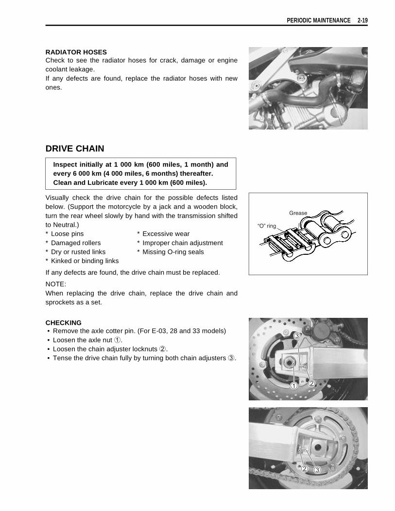
PERIODIC MAINTENANCE 2-19
RADIATOR HOSESCheck to see the radiator hoses for crack, damage or enginecoolant leakage.If any defects are found, replace the radiator hoses with newones.
DRIVE CHAIN
Visually check the drive chain for the possible defects listedbelow. (Support the motorcycle by a jack and a wooden block,turn the rear wheel slowly by hand with the transmission shiftedto Neutral.)* Loose pins * Excessive wear* Damaged rollers * Improper chain adjustment* Dry or rusted links * Missing O-ring seals* Kinked or binding links
If any defects are found, the drive chain must be replaced.
NOTE:When replacing the drive chain, replace the drive chain andsprockets as a set.
CHECKING• Remove the axle cotter pin. (For E-03, 28 and 33 models)• Loosen the axle nut
.• Loosen the chain adjuster locknuts
.• Tense the drive chain fully by turning both chain adjusters
.
Inspect initially at 1 000 km (600 miles, 1 month) andevery 6 000 km (4 000 miles, 6 months) thereafter.Clean and Lubricate every 1 000 km (600 miles).
Grease
“O” ring
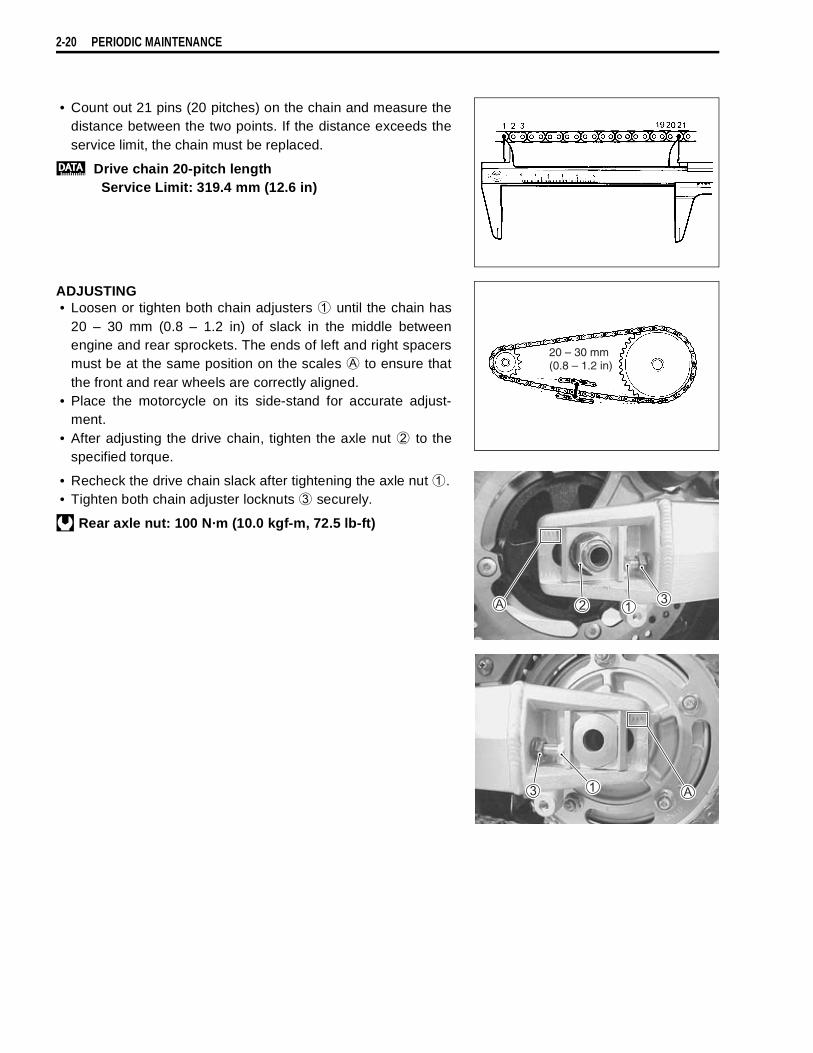
2-20 PERIODIC MAINTENANCE
• Count out 21 pins (20 pitches) on the chain and measure thedistance between the two points. If the distance exceeds theservice limit, the chain must be replaced.
Drive chain 20-pitch lengthService Limit: 319.4 mm (12.6 in)
ADJUSTING• Loosen or tighten both chain adjusters
until the chain has20 – 30 mm (0.8 – 1.2 in) of slack in the middle betweenengine and rear sprockets. The ends of left and right spacersmust be at the same position on the scales
to ensure thatthe front and rear wheels are correctly aligned.
• Place the motorcycle on its side-stand for accurate adjust-ment.
• After adjusting the drive chain, tighten the axle nut
to thespecified torque.
• Recheck the drive chain slack after tightening the axle nut
.• Tighten both chain adjuster locknuts
securely.
Rear axle nut: 100 N·m (10.0 kgf-m, 72.5 lb-ft)
20 – 30 mm(0.8 – 1.2 in)

PERIODIC MAINTENANCE 2-21
CLEANING AND LUBRICATING• Wash the chain with kerosene. If the chain tends to rust
quickly, the intervals must be shortened.
• After washing and drying the chain, oil it with a heavy-weightmotor oil.
BRAKE
BRAKE FLUID LEVEL CHECK• Keep the motorcycle upright and place the handlebars
straight.• Check the brake fluid level by observing the lower limit lines
on the front and rear brake fluid reservoirs.• When the level is below the lower limit line, replenish with
brake fluid that meets the following specification.
Specification and Classification: DOT 4
Do not use trichlene, gasoline or any similar fluids:These fluids have too great a dissolving power for thischain and, what is more important, they can damagethe “O”-rings (or seals) confining the grease in thebush to pin clearance. Remember, high durabilitycomes from the presence of grease in that clearance.
* Do not use any oil sold commercially as “drive chainoil”. Such oil can damage the “O”-rings (or seals).
* The standard drive chain is RK525SMOZ7. SUZUKIrecommends that this standard drive chain shouldbe used for the replacement.
(BRAKE)Inspect initially at 1 000 km (600 miles, 1 month) andevery 6 000 km (4 000 miles, 6 months) thereafter.
(BRAKE HOSE AND BRAKE FLUID)Inspect every 6 000 km (4 000 miles, 6 months).Replace hoses every 4 years. Replace fluid every 2years.
UPPER
LOWER

2-22 PERIODIC MAINTENANCE
• Remove the brake caliper. (Front)
BRAKE PADS
The extent of brake pad wear can be checked by observing thegrooved limit
on the pad. When the wear exceeds thegrooved limit, replace the pads with new ones. ( 6-57, 67)
The brake system of this motorcycle is filled with aglycol-based brake fluid. Do not use or mix differenttypes of fluid such as silicone-based or petro-leum-based. Do not use any brake fluid taken fromold, used or unsealed containers. Never re-use brakefluid left over from the last servicing or stored for along period.
Brake fluid, if it leaks, will interfere with safe runningand immediately discolor painted surfaces. Check thebrake hoses and hose joints for cracks and oil leakagebefore riding.
Replace the brake pad as a set, otherwise braking per-formance will be adversely affected.
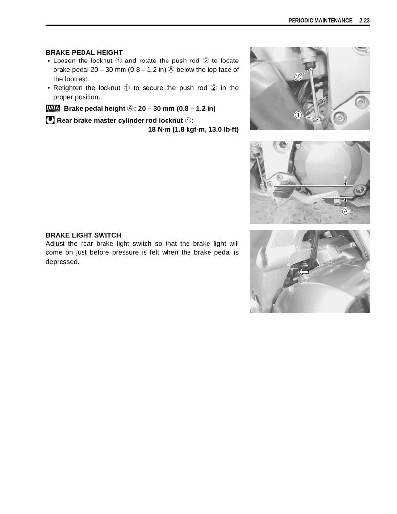
PERIODIC MAINTENANCE 2-23
BRAKE PEDAL HEIGHT• Loosen the locknut
and rotate the push rod
to locatebrake pedal 20 – 30 mm (0.8 – 1.2 in)
below the top face ofthe footrest.
• Retighten the locknut
to secure the push rod
in theproper position.
Brake pedal height
: 20 – 30 mm (0.8 – 1.2 in)
Rear brake master cylinder rod locknut
:18 N·m (1.8 kgf-m, 13.0 lb-ft)
BRAKE LIGHT SWITCHAdjust the rear brake light switch so that the brake light willcome on just before pressure is felt when the brake pedal isdepressed.

2-24 PERIODIC MAINTENANCE
AIR BLEEDING THE BRAKE FLUID CIRCUITAir trapped in the fluid circuit acts like a cushion to absorb alarge proportion of the pressure developed by the master cylin-der and thus interferes with the full braking performance of thebrake caliper. The presence of air is indicated by “sponginess”of the brake lever and also by lack of braking force. Consideringthe danger to which such trapped air exposes the machine andrider, it is essential that, after remounting the brake and restor-ing the brake system to the normal condition, the brake fluid cir-cuit be purged of air in the following manner:
• Fill up the master cylinder reservoir to the “UPPER” line.Place the reservoir cap to prevent entry of dirt.
• Attach a pipe to the air bleeder valve, and insert the free endof the pipe into a receptacle.
Air bleeder valve: 7.5 N·m (0.75 kgf-m, 5.5 lb-ft)
• Front brake: Bleed the air from the air bleeder valve.• Squeeze and release the brake lever several times in rapid
succession and squeeze the lever fully without releasing it.Loosen the bleeder valve by turning it a quarter of a turn sothat the brake fluid runs into the receptacle; this will removethe tension of the brake lever causing it to touch the handle-bar grip. Then, close the valve, pump and squeeze the lever,and open the valve. Repeat this process until the fluid flowinginto the receptacle no longer contains air bubbles.
NOTE:Replenish the brake fluid in the reservoir as necessary whilebleeding the brake system. Make sure that there is always somefluid visible in the reservoir.
• Close the bleeder valve, and disconnect the pipe. Fill the res-ervoir with brake fluid to the “UPPER” line.
• The only difference between bleeding the front and rearbrakes is that the rear master cylinder is actuated by a pedal.
Handle brake fluid with care: the fluid reacts chemi-cally with paint, plastics, rubber materials and so on.

PERIODIC MAINTENANCE 2-25
TIRE
TIRE TREAD CONDITIONOperating the motorcycle with excessively worn tires willdecrease riding stability and consequently invite a dangeroussituation. It is highly recommended to replace a tire when theremaining depth of tire tread reaches the following specification.
09900-20805: Tire depth gauge
Tire tread depthService Limit (FRONT) : 1.6 mm (0.06 in)
(REAR) : 2.0 mm (0.08 in)
TIRE PRESSUREIf the tire pressure is too high or too low, steering will beadversely affected and tire wear increased. Therefore, maintainthe correct tire pressure for good roadability or shorter tire lifewill result. Cold inflation tire pressure is as follows.
TIRE TYPEBRIDGESTONE (Front : TW101F Rear : TW152F)
STEERING
Steering should be adjusted properly for smooth turning of han-dlebars and safe running. Overtight steering prevents smoothturning of the handlebars and too loose steering will cause poorstability. Check that there is no play in the steering stem whilegrasping the lower fork tubes by supporting the machine so thatthe front wheel is off the ground, with the wheel straight ahead,and pull forward. If play is found, perform steering bearingadjustment as described in page 6-32 of this manual.
Inspect every 6 000 km (4 000 miles, 6 months).
COLD INFLATION TIRE PRESSURE
SOLO RINDING DUAL RIDINGkPa kgf/cm² psi kPa kgf/cm² psi
FRONT 250 2.50 36 250 2.50 36REAR 250 2.50 36 280 2.80 41
The standard tire fitted on this motorcycle is 110/80R19M/C (59H) for front and 150/70 R17M/C (69H) forrear. The use of tires other than those specified maycause instability. It is highly recommended to use aSUZUKI Genuine Tire.
Inspect initially at 1 000 km (600 miles, 1 month) andevery 12 000 km (7 500 miles, 12 months) thereafter.
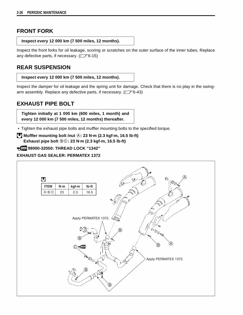
2-26 PERIODIC MAINTENANCE
FRONT FORK
Inspect the front forks for oil leakage, scoring or scratches on the outer surface of the inner tubes. Replaceany defective parts, if necessary. ( 6-15)
REAR SUSPENSION
Inspect the damper for oil leakage and the spring unit for damage. Check that there is no play in the swing-arm assembly. Replace any defective parts, if necessary. ( 6-43)
EXHAUST PIPE BOLT
• Tighten the exhaust pipe bolts and muffler mounting bolts to the specified torque.
Muffler mounting bolt /nut
: 23 N·m (2.3 kgf-m, 16.5 lb-ft)Exhaust pipe bolt
: 23 N·m (2.3 kgf-m, 16.5 lb-ft)
99000-32050: THREAD LOCK ‘‘1342’’
EXHAUST GAS SEALER: PERMATEX 1372
Inspect every 12 000 km (7 500 miles, 12 months).
Inspect every 12 000 km (7 500 miles, 12 months).
Tighten initially at 1 000 km (600 miles, 1 month) andevery 12 000 km (7 500 miles, 12 months) thereafter.
ITEM N·m kgf-m lb-ft
23 2.3 16.5
Apply PERMATEX 1372.
Apply PERMATEX 1372.
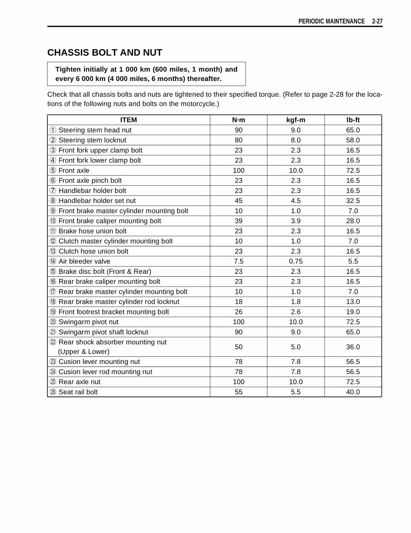
PERIODIC MAINTENANCE 2-27
CHASSIS BOLT AND NUT
Check that all chassis bolts and nuts are tightened to their specified torque. (Refer to page 2-28 for the loca-tions of the following nuts and bolts on the motorcycle.)
Tighten initially at 1 000 km (600 miles, 1 month) andevery 6 000 km (4 000 miles, 6 months) thereafter.
ITEM N·m kgf-m lb-ft
Steering stem head nut 90 9.0 65.0
Steering stem locknut 80 8.0 58.0
Front fork upper clamp bolt 23 2.3 16.5
Front fork lower clamp bolt 23 2.3 16.5
Front axle 100 10.0 72.5
Front axle pinch bolt 23 2.3 16.5
Handlebar holder bolt 23 2.3 16.5
Handlebar holder set nut 45 4.5 32.5
Front brake master cylinder mounting bolt 10 1.0 7.0
Front brake caliper mounting bolt 39 3.9 28.0
Brake hose union bolt 23 2.3 16.5
Clutch master cylinder mounting bolt 10 1.0 7.0
Clutch hose union bolt 23 2.3 16.5
Air bleeder valve 7.5 0.75 5.5
Brake disc bolt (Front & Rear) 23 2.3 16.5
Rear brake caliper mounting bolt 23 2.3 16.5
Rear brake master cylinder mounting bolt 10 1.0 7.0
Rear brake master cylinder rod locknut 18 1.8 13.0
Front footrest bracket mounting bolt 26 2.6 19.0
Swingarm pivot nut 100 10.0 72.5
Swingarm pivot shaft locknut 90 9.0 65.0
Rear shock absorber mounting nut (Upper & Lower)
50 5.0 36.0
Cusion lever mounting nut 78 7.8 56.5
Cusion lever rod mounting nut 78 7.8 56.5
Rear axle nut 100 10.0 72.5
Seat rail bolt 55 5.5 40.0

2-28 PERIODIC MAINTENANCE
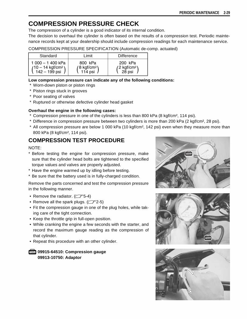
PERIODIC MAINTENANCE 2-29
COMPRESSION PRESSURE CHECKThe compression of a cylinder is a good indicator of its internal condition.The decision to overhaul the cylinder is often based on the results of a compression test. Periodic mainte-nance records kept at your dealership should include compression readings for each maintenance service.
COMPRESSION PRESSURE SPECIFICATION (Automatic de-comp. actuated)
Low compression pressure can indicate any of the following conditions:* Worn-down piston or piston rings* Piston rings stuck in grooves* Poor seating of valves* Ruptured or otherwise defective cylinder head gasket
Overhaul the engine in the following cases:* Compression pressure in one of the cylinders is less than 800 kPa (8 kgf/cm², 114 psi).* Difference in compression pressure between two cylinders is more than 200 kPa (2 kgf/cm², 28 psi).* All compression pressure are below 1 000 kPa (10 kgf/cm², 142 psi) even when they measure more than
800 kPa (8 kgf/cm², 114 psi).
COMPRESSION TEST PROCEDURENOTE:* Before testing the engine for compression pressure, make
sure that the cylinder head bolts are tightened to the specifiedtorque values and valves are properly adjusted.
* Have the engine warmed up by idling before testing.* Be sure that the battery used is in fully-charged condition.
Remove the parts concerned and test the compression pressurein the following manner.
• Remove the radiator. ( 5-4)• Remove all the spark plugs. ( 2-5)• Fit the compression gauge in one of the plug holes, while tak-
ing care of the tight connection.• Keep the throttle grip in full-open position.• While cranking the engine a few seconds with the starter, and
record the maximum gauge reading as the compression ofthat cylinder.
• Repeat this procedure with an other cylinder.
09915-64510: Compression gauge09913-10750: Adaptor
Standard Limit Difference
1 000 – 1 400 kPa10 – 14 kgf/cm2
142 – 199 psi( )800 kPa8 kgf/cm2
114 psi( )200 kPa2 kgf/cm2
28 psi( )

2-30 PERIODIC MAINTENANCE
OIL PRESSURE CHECKCheck periodically the oil pressure in the engine to judge roughly the condition of the moving parts.
OIL PRESSURE SPECIFICATION
If the oil pressure is lower or higher than the specification, the following causes may be considered.
LOW OIL PRESSURE* Clogged oil filter* Oil leakage from the oil passage way* Damaged O-ring* Defective oil pump* Combination of the above items
HIGH OIL PRESSURE* Used of high viscosity engine oil* Clogged oil passage way* Combination of the above items
OIL PRESSURE TEST PROCEDUREStart the engine and check if the oil pressure indicator light isturned on. If it keeps on lighting, check the oil pressure indicatorlight circuit. If it is in good condition, check the oil pressure in thefollowing manner.• Remove the engine under cover
.• Remove the main oil gallery plug
.• Install the oil pressure gauge with attachment in the position
shown in the figure.
• Warm up the engine as follows:Summer 10 min. at 2 000 r/min.Winter 20 min. at 2 000 r/min.
• After warming up, increase the engine speed to 3 000 r/min.(with the engine tachometer), and read the oil pressuregauge.
09915-72410: Oil pressure gauge attachment09915-74521: Oil pressure gauge hose09915-74532: Oil pressure gauge attachment09915-77331: Meter (for high pressure)
Oil gallery plug [M 8]: 18 N·m (1.8 kgf-m, 13.0 lb-ft)
Above 400 kPa (4.0 kgf/cm², 57 psi)Below 700 kPa (7.0 kgf/cm², 100 psi)
at 3 000 r/min., Oil temp. at 60°C (140°F)
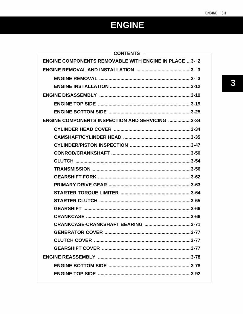
3
6
ENGINE 3-1
CONTENTS
ENGINE
ENGINE COMPONENTS REMOVABLE WITH ENGINE IN PLACE ...3- 2
ENGINE REMOVAL AND INSTALLATION .........................................3- 3
ENGINE REMOVAL .....................................................................3- 3
ENGINE INSTALLATION .............................................................3-12
ENGINE DISASSEMBLY .....................................................................3-19
ENGINE TOP SIDE ......................................................................3-19
ENGINE BOTTOM SIDE ..............................................................3-25
ENGINE COMPONENTS INSPECTION AND SERVICING .................3-34
CYLINDER HEAD COVER ..........................................................3-34
CAMSHAFT/CYLINDER HEAD ...................................................3-35
CYLINDER/PISTON INSPECTION ..............................................3-47
CONROD/CRANKSHAFT ............................................................3-50
CLUTCH .......................................................................................3-54
TRANSMISSION ..........................................................................3-56
GEARSHIFT FORK ......................................................................3-62
PRIMARY DRIVE GEAR ..............................................................3-63
STARTER TORQUE LIMITER .....................................................3-64
STARTER CLUTCH .....................................................................3-65
GEARSHIFT .................................................................................3-66
CRANKCASE ...............................................................................3-66
CRANKCASE-CRANKSHAFT BEARING ...................................3-71
GENERATOR COVER .................................................................3-77
CLUTCH COVER .........................................................................3-77
GEARSHIFT COVER ...................................................................3-77
ENGINE REASSEMBLY ......................................................................3-78
ENGINE BOTTOM SIDE ..............................................................3-78
ENGINE TOP SIDE ......................................................................3-92
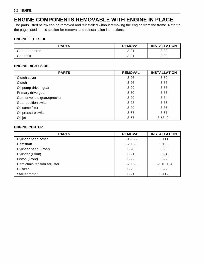
3-2 ENGINE
ENGINE COMPONENTS REMOVABLE WITH ENGINE IN PLACEThe parts listed below can be removed and reinstalled without removing the engine from the frame. Refer tothe page listed in this section for removal and reinstallation instructions.
ENGINE LEFT SIDE
ENGINE RIGHT SIDE
ENGINE CENTER
PARTS REMOVAL INSTALLATIONGenerator rotor 3-31 3-82
Gearshift 3-31 3-80
PARTS REMOVAL INSTALLATIONClutch cover 3-26 3-89Clutch 3-26 3-86
Oil pump driven gear 3-29 3-86Primary drive gear 3-30 3-83
Cam drive idle gear/sprocket 3-29 3-84Gear position switch 3-28 3-85
Oil sump filter 3-29 3-85Oil pressure switch 3-67 3-67
Oil jet 3-67 3-68, 94
PARTS REMOVAL INSTALLATIONCylinder head cover 3-19, 22 3-111Camshaft 3-20, 23 3-105
Cylinder head (Front) 3-20 3-95Cylinder (Front) 3-21 3-94
Piston (Front) 3-22 3-92Cam chain tension adjuster 3-20, 23 3-101, 104
Oil filter 3-25 3-92Starter motor 3-21 3-112

ENGINE 3-3
ENGINE REMOVAL AND INSTALLATIONENGINE REMOVALBefore taking the engine out of the frame, wash the engineusing a steam cleaner. Engine removal is sequentially explainedin the following steps. Reinstall the engine by reversing theremoval procedure.
• Drain engine oil. ( 2-12)• Drain engine coolant. ( 2-17)• Remove the seat. ( 6-4)
• Disconnect the battery
lead wire.
• Remove the engine under cover
.
• Remove the fuel tank side covers
, cowlings
and innercowling. ( 6-6)
• Remove the radiator and water hoses.

3-4 ENGINE
• Remove the fuel tank
.
• Remove the air cleaner.
• Remove the throttle body.
• Remove the spark plug caps.• Remove the camshaft position sensor lead wire coupler
.
• Disconnect the gear position switch lead wire coupler
.
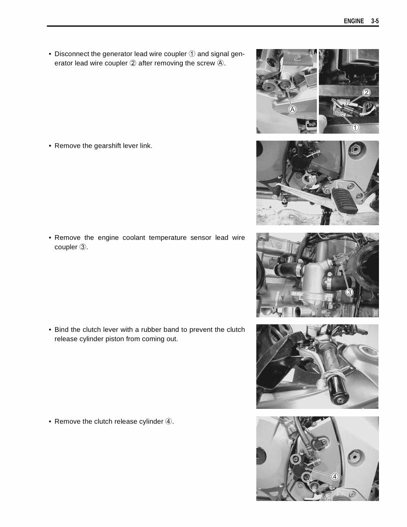
ENGINE 3-5
• Disconnect the generator lead wire coupler
and signal gen-erator lead wire coupler
after removing the screw
.
• Remove the gearshift lever link.
• Remove the engine coolant temperature sensor lead wirecoupler
.
• Bind the clutch lever with a rubber band to prevent the clutchrelease cylinder piston from coming out.
• Remove the clutch release cylinder
.
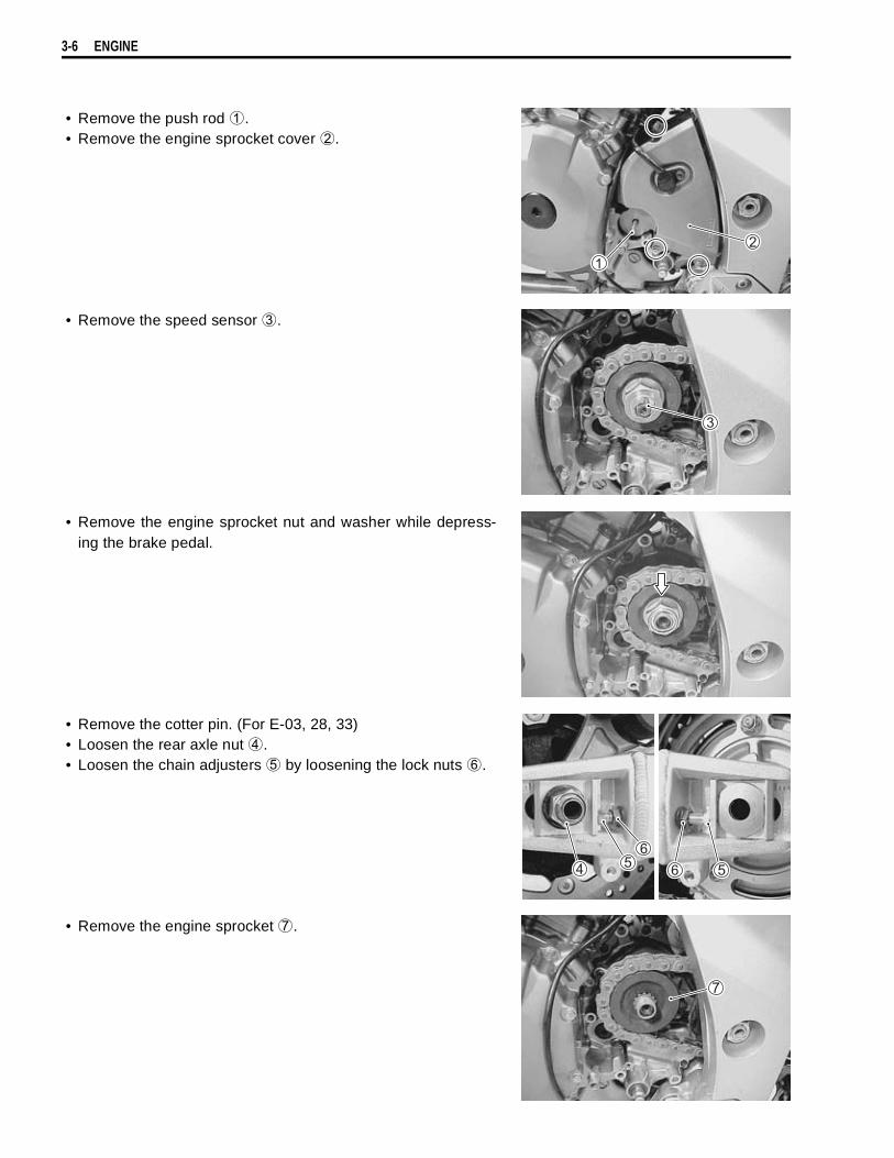
3-6 ENGINE
• Remove the push rod
.• Remove the engine sprocket cover
.
• Remove the speed sensor
.
• Remove the engine sprocket nut and washer while depress-ing the brake pedal.
• Remove the cotter pin. (For E-03, 28, 33)• Loosen the rear axle nut
.• Loosen the chain adjusters
by loosening the lock nuts
.
• Remove the engine sprocket
.
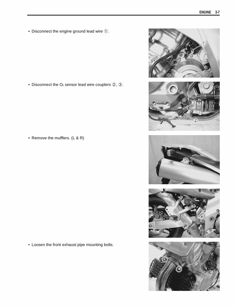
ENGINE 3-7
• Disconnect the engine ground lead wire
.
• Disconnect the O² sensor lead wire couplers
,
.
• Remove the mufflers. (L & R)
• Loosen the front exhaust pipe mounting bolts.

3-8 ENGINE
• Remove the front exhaust pipe.
• Remove the mud guard
.• Remove the rear exhaust pipe.
• Remove the right footrest bracket and brake pedal.
• Remove the oil cooler
.
• Disconnect the starter motor lead wire
and oil pressureswitch lead wire
.
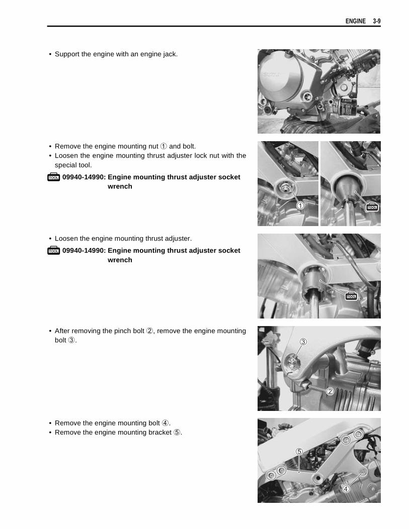
ENGINE 3-9
• Support the engine with an engine jack.
• Remove the engine mounting nut
and bolt.• Loosen the engine mounting thrust adjuster lock nut with the
special tool.
09940-14990: Engine mounting thrust adjuster socketwrench
• Loosen the engine mounting thrust adjuster.
09940-14990: Engine mounting thrust adjuster socketwrench
• After removing the pinch bolt
, remove the engine mountingbolt
.
• Remove the engine mounting bolt
.• Remove the engine mounting bracket
.
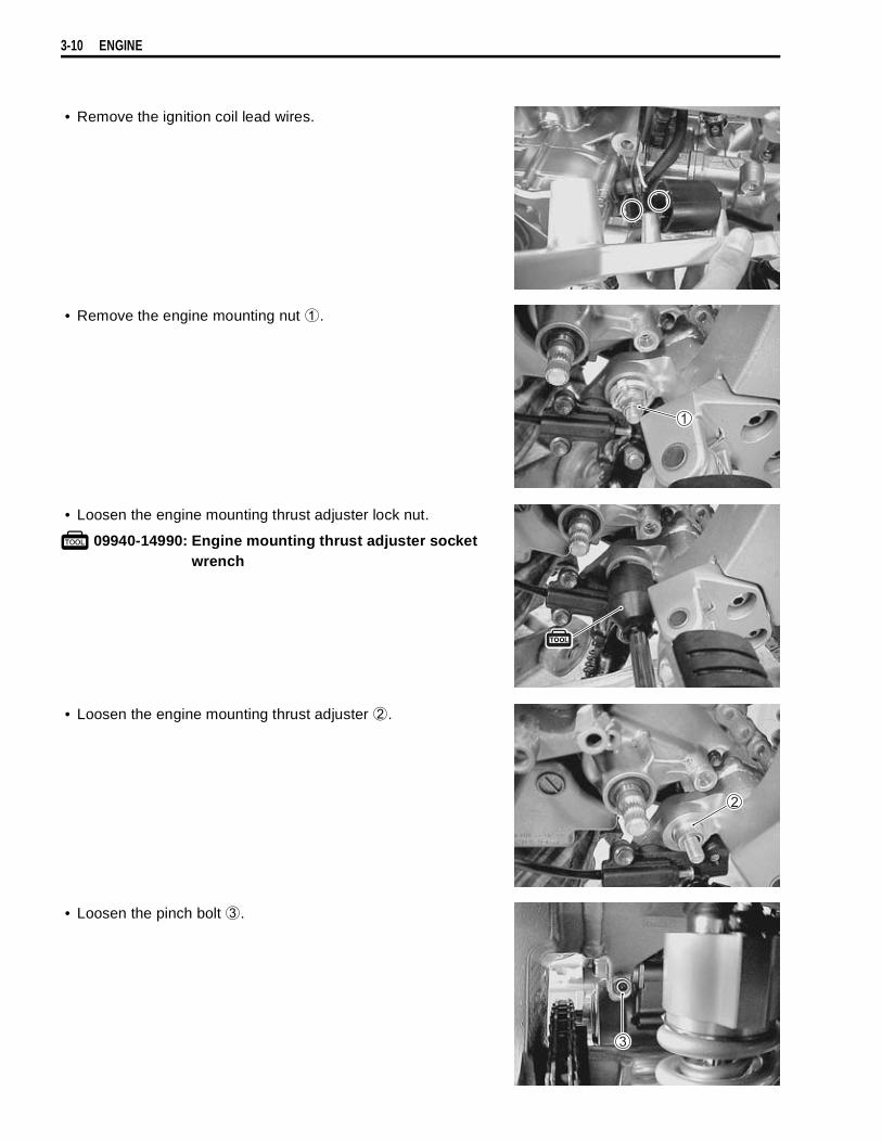
3-10 ENGINE
• Remove the ignition coil lead wires.
• Remove the engine mounting nut
.
• Loosen the engine mounting thrust adjuster lock nut.
09940-14990: Engine mounting thrust adjuster socketwrench
• Loosen the engine mounting thrust adjuster
.
• Loosen the pinch bolt
.
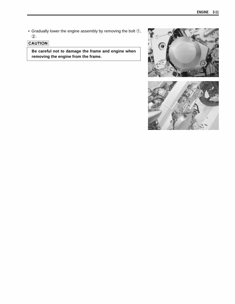
ENGINE 3-11
• Gradually lower the engine assembly by removing the bolt
,
.
Be careful not to damage the frame and engine whenremoving the engine from the frame.

3-12 ENGINE
ENGINE INSTALLATIONRemount the engine in the reverse order of engine removal.Pay attention to the following points:
NOTE:* The engine mounting nuts are self-locking.* Once the nut has been removed, it is no longer of any use. Be sure to use new nuts, and then tighten them
to the specified torque.
ITEM N·m kgf-m lb-ft
55 5.5 40.0
23 2.3 16.5
12 1.2 8.5
45 4.5 32.5
75 7.5 54.0
FWD
RHLH
RHLH
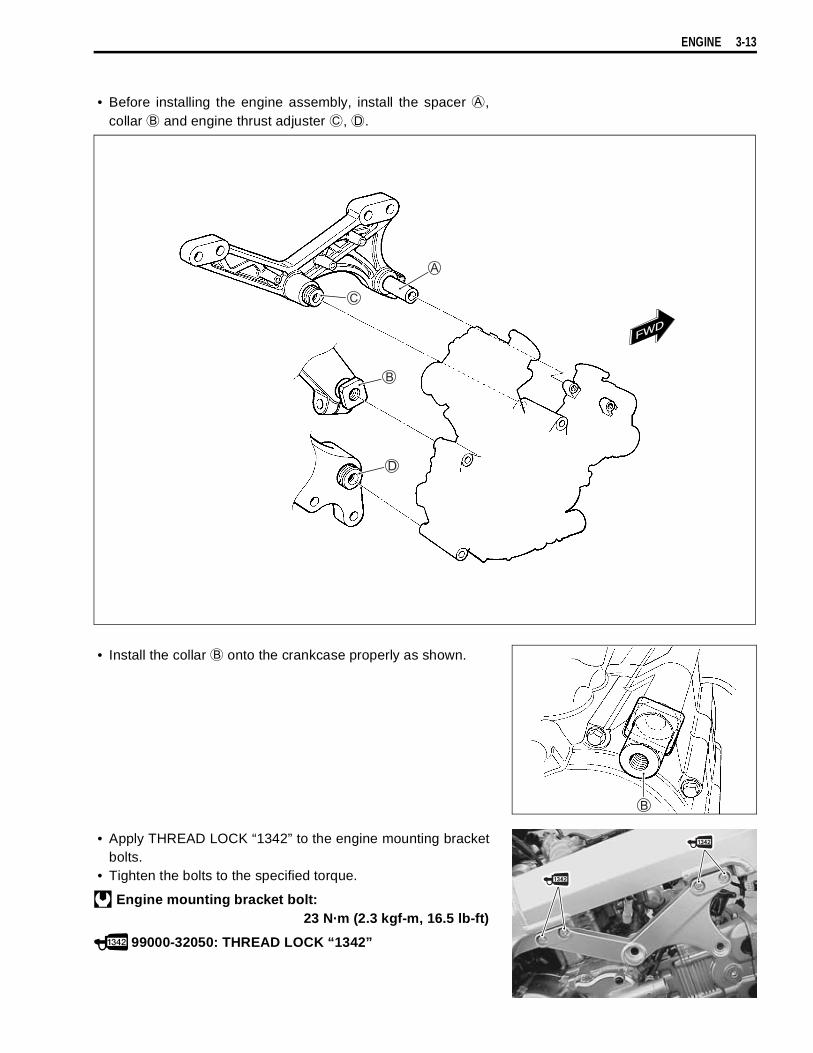
ENGINE 3-13
• Before installing the engine assembly, install the spacer
,collar
and engine thrust adjuster
,
.
• Install the collar
onto the crankcase properly as shown.
• Apply THREAD LOCK “1342” to the engine mounting bracketbolts.
• Tighten the bolts to the specified torque.
Engine mounting bracket bolt:23 N·m (2.3 kgf-m, 16.5 lb-ft)
99000-32050: THREAD LOCK “1342”
FWD
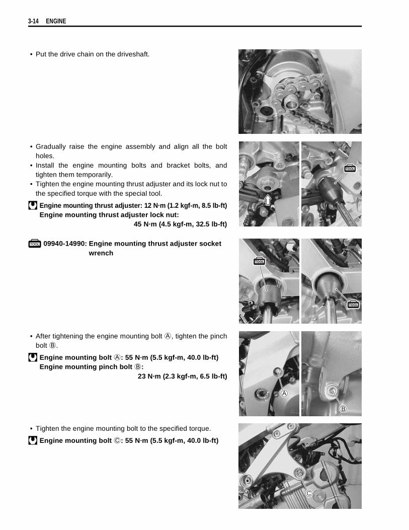
3-14 ENGINE
• Put the drive chain on the driveshaft.
• Gradually raise the engine assembly and align all the boltholes.
• Install the engine mounting bolts and bracket bolts, andtighten them temporarily.
• Tighten the engine mounting thrust adjuster and its lock nut tothe specified torque with the special tool.
Engine mounting thrust adjuster: 12 N·m (1.2 kgf-m, 8.5 lb-ft)Engine mounting thrust adjuster lock nut:
45 N·m (4.5 kgf-m, 32.5 lb-ft)
09940-14990: Engine mounting thrust adjuster socketwrench
• After tightening the engine mounting bolt
, tighten the pinchbolt
.
Engine mounting bolt
: 55 N·m (5.5 kgf-m, 40.0 lb-ft)Engine mounting pinch bolt
:23 N·m (2.3 kgf-m, 6.5 lb-ft)
• Tighten the engine mounting bolt to the specified torque.
Engine mounting bolt
: 55 N·m (5.5 kgf-m, 40.0 lb-ft)

ENGINE 3-15
• Tighten the engine mounting nut
,
to the specifiedtorque.
Engine mounting nut
: 75 N·m (7.5 kgf-m, 54.0 lb-ft)Engine mounting nut
: 55 N·m (5.5 kgf-m, 40.0 lb-ft)
• After tightening the bolt
, tighten the pinch bolt
to thespecified torque.
Engine mounting bolt
: 55 N·m (5.5 kgf-m, 40.0 lb-ft)Engine mounting pinch bolt
:23 N·m (2.3 kgf-m, 16.5 lb-ft)
• Install the washers and tighten the union bolt to the specifiedtorque.
Oil hose union bolt: 23 N·m (2.3 kgf-m, 16.5 lb-ft)
• Install the new gaskets.
• Install the exhaust pipes and mufflers.
NOTE:Apply THREAD LOCK “1342” to the bolt
.
99000-32050: THREAD LOCK “1342”

3-16 ENGINE
• Adjust the brake pedal height.
Brake pedal height
Standard: 20 – 30 mm (0.8 – 1.2 in)
• Install the gearshift arm as shown.
Gearshift arm angle
: Approx. 60°
ITEM N·m kgf-m lb-ft
23 2.3 16.5
Apply PERMATEX 1372.
Apply PERMATEX 1372.
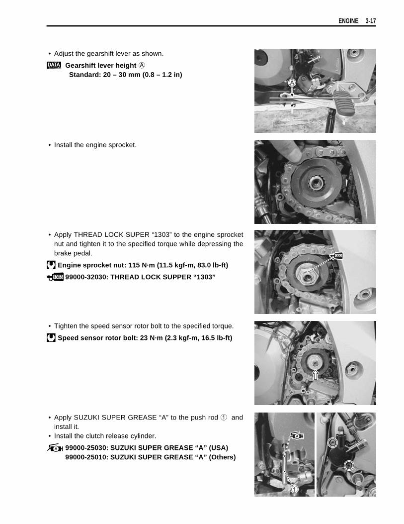
ENGINE 3-17
• Adjust the gearshift lever as shown.
Gearshift lever height
Standard: 20 – 30 mm (0.8 – 1.2 in)
• Install the engine sprocket.
• Apply THREAD LOCK SUPER “1303” to the engine sprocketnut and tighten it to the specified torque while depressing thebrake pedal.
Engine sprocket nut: 115 N·m (11.5 kgf-m, 83.0 lb-ft)
99000-32030: THREAD LOCK SUPPER “1303”
• Tighten the speed sensor rotor bolt to the specified torque.
Speed sensor rotor bolt: 23 N·m (2.3 kgf-m, 16.5 lb-ft)
• Apply SUZUKI SUPER GREASE “A” to the push rod
andinstall it.
• Install the clutch release cylinder.
99000-25030: SUZUKI SUPER GREASE “A” (USA)99000-25010: SUZUKI SUPER GREASE “A” (Others)
3-18 ENGINE
• After installing the engine, route the wire harness, cables andhoses properly. ( 8-14)
• Adjust the following items.* Engine oil 2-12* Engine coolant 2-17* Engine idle speed 2-14* Throttle cable play 2-14
Engine oil capacityOil change: 2.7 L (2.9/2.4 US/lmp qt)Oil and filter change: 2.9 L (3.1/2.6 US/lmp qt)Engine overhaul: 3.3 L (3.5/2.9 US/lmp qt)

ENGINE 3-19
ENGINE DISASSEMBLYENGINE TOP SIDE• Remove the thermostat.
• Remove the valve timing inspection plug
and generatorcover plug
.
FRONT CYLINDER HEAD COVER• Remove the front cylinder head cover
.
• Turn the crankshaft to bring the “F | T” line on generator rotorto the index mark of the valve inspection hole and also tobring the cams to the position as shown.
NOTE:At the above condition, the No.1 (Front) cylinder is at TDC ofcompression stroke and also the engraved lines
on the cam-shafts are parallel with the mating surface of the cylinder headcover.
FRONT
Frontcylinder head
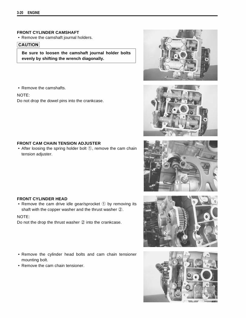
3-20 ENGINE
FRONT CYLINDER CAMSHAFT• Remove the camshaft journal holders.
• Remove the camshafts.
NOTE:Do not drop the dowel pins into the crankcase.
FRONT CAM CHAIN TENSION ADJUSTER• After loosing the spring holder bolt
, remove the cam chaintension adjuster.
FRONT CYLINDER HEAD• Remove the cam drive idle gear/sprocket
by removing itsshaft with the copper washer and the thrust washer
.
NOTE:Do not the drop the thrust washer
into the crankcase.
• Remove the cylinder head bolts and cam chain tensionermounting bolt.
• Remove the cam chain tensioner.
Be sure to loosen the camshaft journal holder boltsevenly by shifting the wrench diagonally.
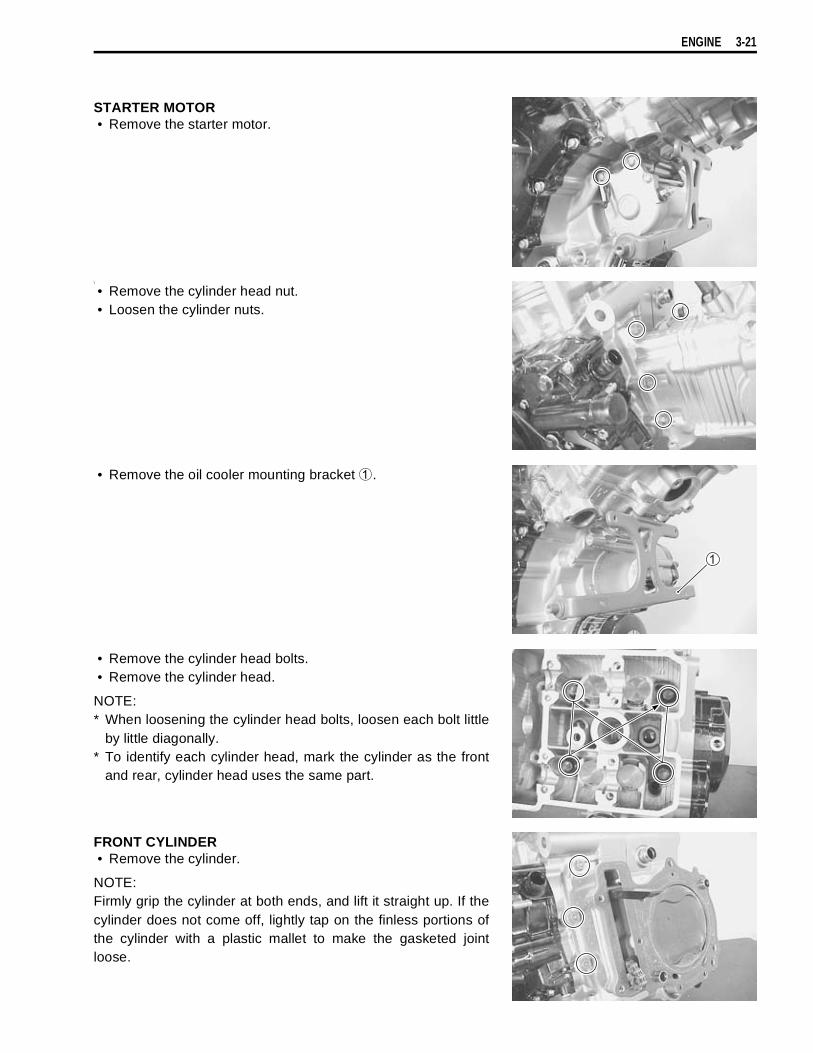
ENGINE 3-21
STARTER MOTOR• Remove the starter motor.
\
• Remove the cylinder head nut.• Loosen the cylinder nuts.
• Remove the oil cooler mounting bracket
.
• Remove the cylinder head bolts.• Remove the cylinder head.
NOTE:* When loosening the cylinder head bolts, loosen each bolt little
by little diagonally.* To identify each cylinder head, mark the cylinder as the front
and rear, cylinder head uses the same part.
FRONT CYLINDER• Remove the cylinder.
NOTE:Firmly grip the cylinder at both ends, and lift it straight up. If thecylinder does not come off, lightly tap on the finless portions ofthe cylinder with a plastic mallet to make the gasketed jointloose.
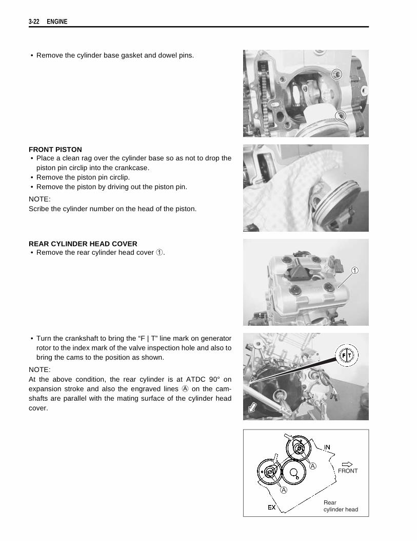
3-22 ENGINE
• Remove the cylinder base gasket and dowel pins.
FRONT PISTON• Place a clean rag over the cylinder base so as not to drop the
piston pin circlip into the crankcase.• Remove the piston pin circlip.• Remove the piston by driving out the piston pin.
NOTE:Scribe the cylinder number on the head of the piston.
REAR CYLINDER HEAD COVER• Remove the rear cylinder head cover
.
• Turn the crankshaft to bring the “F | T” line mark on generatorrotor to the index mark of the valve inspection hole and also tobring the cams to the position as shown.
NOTE:At the above condition, the rear cylinder is at ATDC 90° onexpansion stroke and also the engraved lines
on the cam-shafts are parallel with the mating surface of the cylinder headcover.
FRONT
Rearcylinder head

ENGINE 3-23
REAR CYLINDER CAMSHAFT• Remove the two camshaft journal holders.
• Remove the camshafts.
NOTE:Do not drop the dowel pins into the crankcase.
REAR CAM CHAIN TENSION ADJUSTER• After loosing the spring holder bolt
, remove the cam chaintension adjuster.
REAR CYLINDER HEAD• Remove the cam drive idle gear/sprocket
by removing itsshaft, the copper washer and the thrust washer
.
NOTE:Do not drop the thrust washer
into the crankcase.
Pull the front cam chain upward, or the chain will becaught between the crankcase and cam drive idlegear/sprocket when turning the crankshaft.
Be sure to loosen the camshaft journal holder boltsevenly by shifting the wrench diagonally.
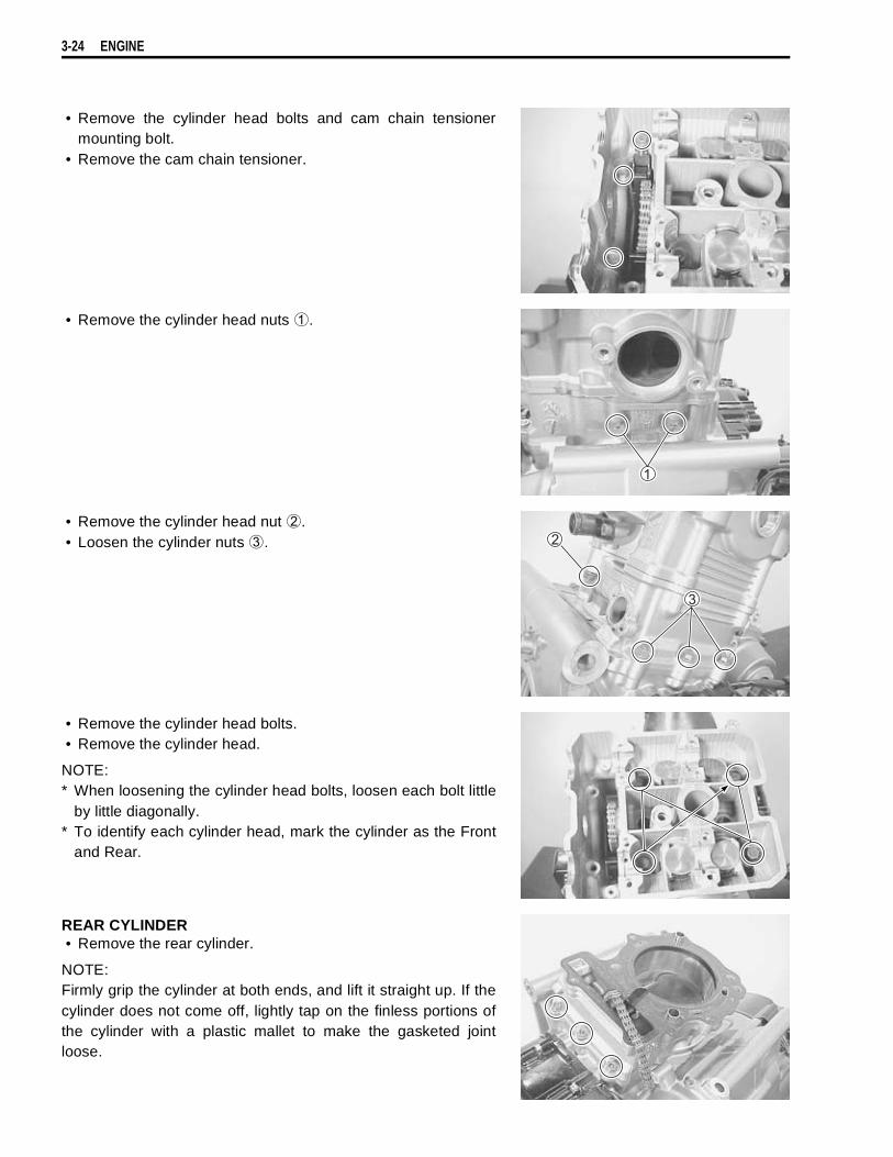
3-24 ENGINE
• Remove the cylinder head bolts and cam chain tensionermounting bolt.
• Remove the cam chain tensioner.
• Remove the cylinder head nuts
.
• Remove the cylinder head nut
.• Loosen the cylinder nuts
.
• Remove the cylinder head bolts.• Remove the cylinder head.
NOTE:* When loosening the cylinder head bolts, loosen each bolt little
by little diagonally.* To identify each cylinder head, mark the cylinder as the Front
and Rear.
REAR CYLINDER• Remove the rear cylinder.
NOTE:Firmly grip the cylinder at both ends, and lift it straight up. If thecylinder does not come off, lightly tap on the finless portions ofthe cylinder with a plastic mallet to make the gasketed jointloose.

ENGINE 3-25
• Remove the cylinder base gasket and dowel pins.
REAR PISTON• Place a clean rag over the cylinder base so as not to drop the
piston pin circlip into the crankcase.• Remove the piston pin circlip.• Remove the piston by driving out the piston pin.
NOTE:Scribe the cylinder number on the head of the piston.
ENGINE BOTTOM SIDEOIL FILTER• Remove the oil filter with the special tool.
09915-40610: Oil filter wrench
• Remove the generator cover.
• Remove the starter torque limiter
and starter idle gear
.
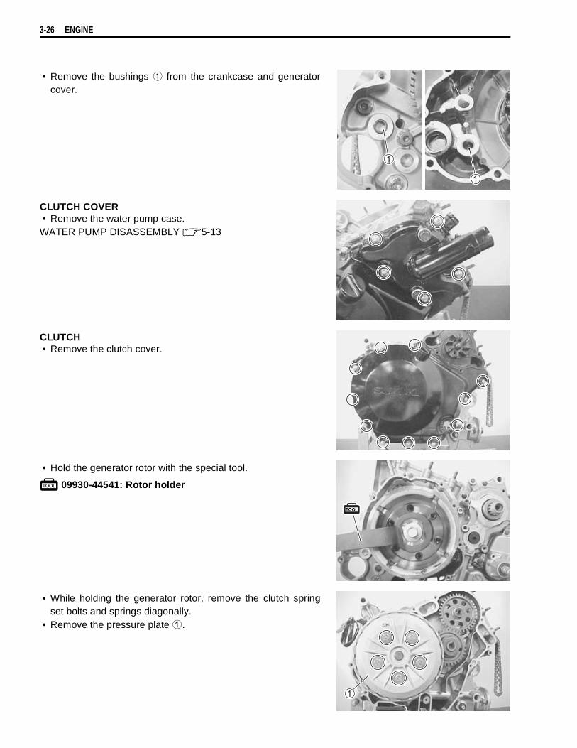
3-26 ENGINE
• Remove the bushings
from the crankcase and generatorcover.
CLUTCH COVER• Remove the water pump case.
WATER PUMP DISASSEMBLY 5-13
CLUTCH• Remove the clutch cover.
• Hold the generator rotor with the special tool.
09930-44541: Rotor holder
• While holding the generator rotor, remove the clutch springset bolts and springs diagonally.
• Remove the pressure plate
.
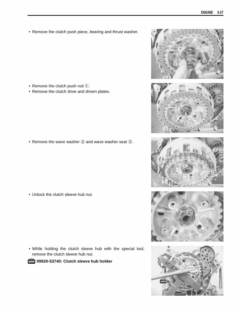
ENGINE 3-27
• Remove the clutch push piece, bearing and thrust washer.
• Remove the clutch push rod
.• Remove the clutch drive and driven plates.
• Remove the wave washer
and wave washer seat
.
• Unlock the clutch sleeve hub nut.
• While holding the clutch sleeve hub with the special tool,remove the clutch sleeve hub nut.
09920-53740: Clutch sleeve hub holder
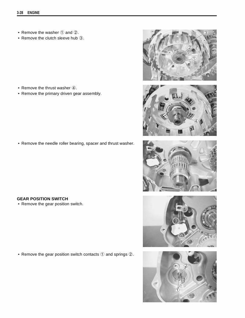
3-28 ENGINE
• Remove the washer
and
.• Remove the clutch sleeve hub
.
• Remove the thrust washer
.• Remove the primary driven gear assembly.
• Remove the needle roller bearing, spacer and thrust washer.
GEAR POSITION SWITCH• Remove the gear position switch.
• Remove the gear position switch contacts
and springs
.

ENGINE 3-29
OIL SUMP FILTER• Remove the oil sump filter.
OIL PUMP• Remove the oil pump driven gear
by removing the snapring.
09900-06107: Snap ring pliers
• Remove the pin
and washer
.
NOTE:Do not drop the snap ring, pin and washer into the crankcase.
• Hold the generator rotor with the special tool.
09930-44541: Rotor holder
CAM DRIVE IDLE GEAR/SPROCKET• While holding the generator rotor, remove the cam drive idle
gear/sprocket nut.

3-30 ENGINE
• Insert a suitable bar into the holes of primary drive gears toalign the teeth of scissors gears.
• Remove the cam drive idle gear/sprocket and cam chain.
• Remove the key
.
PRIMARY DRIVE GEAR• Hold the generator rotor with the special tool.
09930-44541: Rotor holder
• While holding the generator rotor, remove the primary drivegear nut.
• Remove the washer
.• Remove the primary drive gear assembly
.
This bolt has left-hand thread. Turning it counter-clockwise may cause damage.
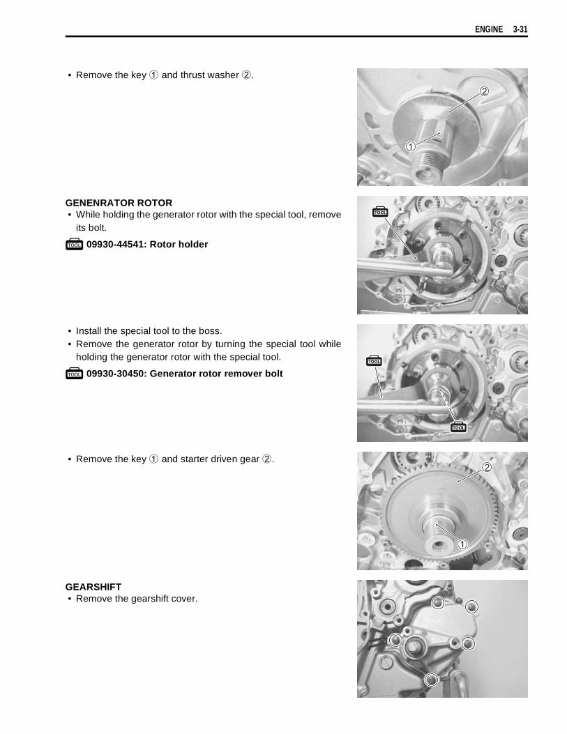
ENGINE 3-31
• Remove the key
and thrust washer
.
GENENRATOR ROTOR• While holding the generator rotor with the special tool, remove
its bolt.
09930-44541: Rotor holder
• Install the special tool to the boss.• Remove the generator rotor by turning the special tool while
holding the generator rotor with the special tool.
09930-30450: Generator rotor remover bolt
• Remove the key
and starter driven gear
.
GEARSHIFT• Remove the gearshift cover.

3-32 ENGINE
• Draw out the gearshift shaft
.
• Remove the gearshift cam plate
.• Remove the gearshift cam stopper
.
• Remove the engine sprocket spacer
.
• Remove the cam drive idle gear shaft
.• Remove the crankcase bolts.

ENGINE 3-33
• Separator the crankcase into 2 parts, right and left with thecrankcase separating tool.
09920-13120: Crankcase separating tool
NOTE:* Fit the crankcase separating tool, so that the tool arms are in
parallel with the side of crankcase.* The crankshaft and transmission components should remain
in the left crankcase half.* When separating the crankcase, tap the end of the counter-
shaft with a plastic hammer.
• Remove the gearshift fork shafts, gearshift forks and gearshiftcam.
• Remove the countershaft and driveshaft.
• Remove the crankshaft.
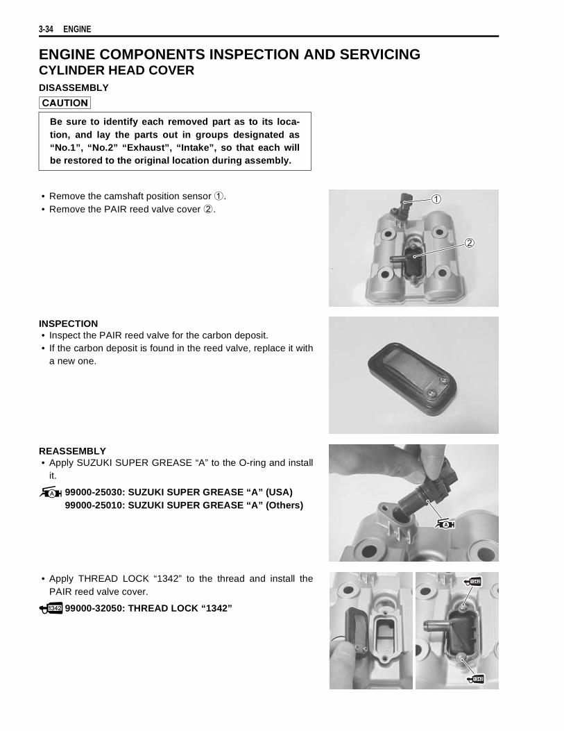
3-34 ENGINE
ENGINE COMPONENTS INSPECTION AND SERVICINGCYLINDER HEAD COVERDISASSEMBLY
• Remove the camshaft position sensor
.• Remove the PAIR reed valve cover
.
INSPECTION• Inspect the PAIR reed valve for the carbon deposit.• If the carbon deposit is found in the reed valve, replace it with
a new one.
REASSEMBLY• Apply SUZUKI SUPER GREASE “A” to the O-ring and install
it.
99000-25030: SUZUKI SUPER GREASE “A” (USA)99000-25010: SUZUKI SUPER GREASE “A” (Others)
• Apply THREAD LOCK “1342” to the thread and install thePAIR reed valve cover.
99000-32050: THREAD LOCK “1342”
Be sure to identify each removed part as to its loca-tion, and lay the parts out in groups designated as“No.1”, “No.2” “Exhaust”, “Intake”, so that each willbe restored to the original location during assembly.

ENGINE 3-35
CAMSHAFT/CYLINDER HEAD
CAMSHAFTAll camshafts should be checked for runout and also for wear ofcams and journals if the engine has been noted as giving abnor-mal noise, vibration or lack power output. Any of these condi-tions may be caused by camshafts worn down or distorted to theservice limit.The camshafts can be identified by the engraved letter.
No.1 (Front) intake camshaft (“INF” and “I”: Intake)
No.1 (Front) exhaust camshaft (“EXF” and “E”: Exhaust)
No.2 (Rear) intake camshaft (“INR” and “I”: Intake)
No.2 (Rear) exhaust camshaft (“EXR” and “E”: Exhaust)
CAM WEARWorn-down cams are often the cause of mistimed valve opera-tion resulting in reduced power output.The limit of cam wear is specified for both intake and exhaustcams in terms of cam height
, which is to be measured with amicrometer. Replace camshaft if it wears worn down to the limit.
Cam height
Service Limit (IN) : 35.98 mm (1.417 in)(EX) : 35.38 mm (1.393 in)
09900-20202: Micrometer (25 – 50 mm)
Be sure to identify each removed part as to its loca-tion, and lay the parts out in groups designated as“No.1”, “No.2”, “Exhaust”, “Intake”, so that each willbe restored to the original location during assembly.
“FRONT” “REAR”
“I” “I”“E” “E”
“INF” “INR” “EXR”“EXF”
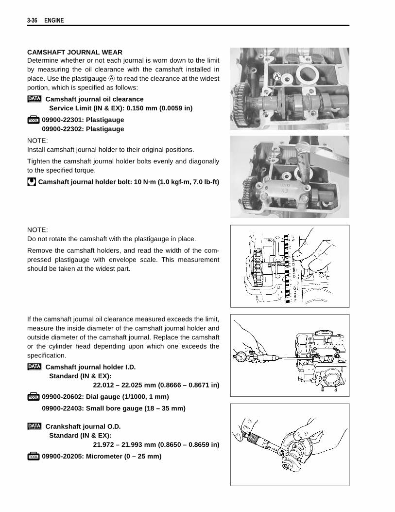
3-36 ENGINE
CAMSHAFT JOURNAL WEARDetermine whether or not each journal is worn down to the limitby measuring the oil clearance with the camshaft installed inplace. Use the plastigauge
to read the clearance at the widestportion, which is specified as follows:
Camshaft journal oil clearanceService Limit (IN & EX): 0.150 mm (0.0059 in)
09900-22301: Plastigauge09900-22302: Plastigauge
NOTE:Install camshaft journal holder to their original positions.
Tighten the camshaft journal holder bolts evenly and diagonallyto the specified torque.
Camshaft journal holder bolt: 10 N·m (1.0 kgf-m, 7.0 lb-ft)
NOTE:Do not rotate the camshaft with the plastigauge in place.
Remove the camshaft holders, and read the width of the com-pressed plastigauge with envelope scale. This measurementshould be taken at the widest part.
If the camshaft journal oil clearance measured exceeds the limit,measure the inside diameter of the camshaft journal holder andoutside diameter of the camshaft journal. Replace the camshaftor the cylinder head depending upon which one exceeds thespecification.
Camshaft journal holder I.D.Standard (IN & EX):
22.012 – 22.025 mm (0.8666 – 0.8671 in)
09900-20602: Dial gauge (1/1000, 1 mm)
09900-22403: Small bore gauge (18 – 35 mm)
Crankshaft journal O.D.Standard (IN & EX):
21.972 – 21.993 mm (0.8650 – 0.8659 in)
09900-20205: Micrometer (0 – 25 mm)

ENGINE 3-37
CAMSHAFT RUNOUTMeasure the runout with a dial gauge. Replace the camshaft ifthe runout exceeds the limit.
Camshaft runoutService Limit (IN & EX): 0.10 mm (0.004 in)
09900-20607: Dial gauge (1/100 mm, 10 mm)09900-20701: Magnetic stand09900-21304: V-block (100 mm)
CAM GEAR AND AUTOMATIC-DECOMP.Inspect the cam gear teeth for wear and damage.Inspect the automatic-decomp. for damage and smooth opera-tion.If there are unusual, replace the camshaft assembly and camchain as a set.
CAM CHAIN TENSION ADJUSTERThe cam chain tension adjusters are maintained at the propercam chain tension automatically.Unlock the ratchet
, and move the push rod
in place to seeif it slides smoothly. If any stickiness is noted or ratchet mecha-nism is faulty, replace the cam chain tension adjuster assemblywith a new one.
Front cam chain tension adjuster
Rear cam chain tension adjuster
CAM CHAIN GUIDE AND CAM CHAIN TENSIONERCheck the cam chain guide and tensioner for wear and damage.If they are found to be damaged, replace them with the newones.
Front cam chain tensioner
Rear cam chain tensioner
Front and Rear cam chain guide
Do not attempt to disassemble the cam gears andautomatic-decomp. assembly. They are unserviceable.
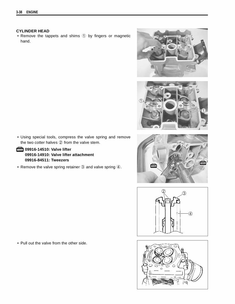
3-38 ENGINE
CYLINDER HEAD• Remove the tappets and shims
by fingers or magnetichand.
• Using special tools, compress the valve spring and removethe two cotter halves
from the valve stem.
09916-14510: Valve lifter09916-14910: Valve lifter attachment09916-84511: Tweezers
• Remove the valve spring retainer
and valve spring
.
• Pull out the valve from the other side.

ENGINE 3-39
• Remove the oil seals
and the spring seats
.
CYLINDER HEAD DISTORTIONDecarbonize the combustion chambers.Check the gasketed surface of the cylinder head for distortionwith a straightedge and thickness gauge, taking a clearancereading at several places indicated. If the largest reading at anyposition of the straightedge exceeds the limit, replace the cylin-der head.
Cylinder head distortionService Limit: 0.05 mm (0.002 in)
09900-20803: Thickness gauge
VALVE STEM RUNOUTSupport the valve with “V” blocks, as shown, and check itsrunout with a dial gauge.The valve must be replaced if the runout exceeds the limit.
Valve stem runoutService Limit: 0.05 mm (0.002 in)
09900-20607: Dial gauge (1/100 mm)09900-20701: Magnetic stand09900-21304: V-block (100 mm)
VALVE HEAD RADIAL RUNOUTPlace the dial gauge at right angles to the valve head face, andmeasure the valve head radial runout.If it measures more than the limit, replace the valve.
Valve head radial runoutService Limit: 0.03 mm (0.001 in)
09900-20607: Dial gauge (1/100 mm)09900-20701: Magnetic stand09900-21304: V-block (100 mm)
Do not reuse the removed oil seals.

3-40 ENGINE
VALVE FACE WEARVisually inspect each valve for wear of its seating face. Replaceany valve with an abnormally worn face. The thickness
decreases as the wear of the face advances.Measure the thickness and, if the thickness is found to havebeen reduced to the limit, replace it.
Valve head thickness
Service Limit: 0.5 mm (0.02 in)
09900-20101: Vernier calipers
VALVE STEM DEFLECTIONLift the valve about 10 mm (0.39 in) from the valve seat.Measure the valve stem deflection in two directions, “X” and “Y”,perpendicular to each other, by positioning the dial gauge asshown. If the deflection measured exceeds the limit, (see below)then determine whether the valve or the guide should bereplaced with a new one.
Valve stem deflection (IN & EX)Service Limit: 0.35 mm (0.014 in)
09900-20607: Dial gauge (1/100 mm)09900-20701: Magnetic stand
VALVE STEM WEARIf the valve stem is worn down to the limit, as measured with amicrometer, where the clearance is found to be in excess of thelimit indicated, replace the valve; if the stem is within the limit,then replace the guide. After replacing valve or guide, be sure torecheck the clearance.
Valve stem O.D.Standard (IN) : 5.475 – 5.490 mm (0.2156 – 0.2161 in)
(EX) : 5.455 – 5.470 mm (0.2148 – 0.2154 in)
09900-20205: Micrometer (0 – 25 mm)
NOTE:If valve guides have to be removed for replacement afterinspecting related parts, carry out the steps shown in valveguide servicing.
VALVE GUIDE SERVICING• Using the valve guide remover, drive the valve guide out
toward the intake or exhaust camshaft side.
09916-44910: Valve guide remover/installer
NOTE:* Discard the removed valve guide subassemblies.* Only oversized valve guides are available as replacement
parts. (Part No.11115-32E70)

ENGINE 3-41
• Re-finish the valve guide holes in cylinder head with thereamer and handle.
09916-34580: Valve guide reamer09916-34542: Reamer handle
• Oil the stem hole, too, of each valve guide and drive the guideinto the guide hole with the valve guide installer and attach-ment.
09916-44910: Valve guide remover/installer09916-53340: Attachment
• After fitting the valve guides, re-finish their guiding bores withthe reamer. Be sure to clean and oil the guides after reaming.
09916-34550: Valve guide reamer09916-34542: Reamer handle
NOTE:Insert the reamer from the combustion chamber and always turnthe reamer handle clockwise.
VALVE SEAT WIDTH• Coat the valve seat uniformly with Prussian blue. Fit the valve
and tap the coated seat with the valve face in a rotating man-ner, in order to obtain a clear impression of the seating con-tact. In this operation, use the valve lapper to hold the valvehead.
Failure to oil the valve guide hole before driving thenew guide into place may result in a damaged guide orhead.
Valveguide
Cylinderhead

3-42 ENGINE
• The ring-like dye impression left on the valve face must becontinuous without any break. In addition, the width of the dyering, which is the visualized seat “width”, must be within thefollowing specification:
Valve seat width
Standard: 0.9 – 1.1 mm (0.035 – 0.043 in)
09916-10911: Valve lapper set
If either requirement is not met, correct the seat by servicing isas follows:
VALVE SEAT SERVICINGThe valve seats for both intake and exhaust valves aremachined to four different angles. (The seat contact surface iscut 45°.)
NOTE:The valve seat contact area must be inspected after each cut.
09916-21111: Valve seat cutter set09916-24210: Valve seat cutter (N-615)09916-24480: Solid pilot (N-140-5.5)09916-24810: Valve seat cutter (N-626)09916-27710: Valve seat cutter (N-211)
• Insert the solid pilot with a slight rotation. Seat the pilotsnugly. Install the 45° cutter, attachment and T-handle.
• Using the 45° cutter, descale and clean up the seat with oneor two turns.
• Inspect the seat by the previously described seat width mea-surement procedure. If the seat is pitted or burned, additionalseat conditioning with the 45° cutter is required.
NOTE:Cut only the minimum amount necessary from the seat to pre-vent the possibility of the tappet shim replacement.
INTAKE EXHAUST45° N-615 or N-626 N-615 or N-626
60° N-211 N-21115° N-615
30° N-626
INTAKE EXHAUST
Valve seat Valve seat
60˚30˚
45˚15˚
45˚
60˚

ENGINE 3-43
If the contact area is too high on the valve, or if it is too wide, usethe 15°/60° cutters (for exhaust side) and 30°/60° cutters (forintake side) to lower and narrow the contact area.
If the contact area is too low or too narrow, use the 45° cutter toraise and widen the contact area.
• After the desired seat position and width is achieved, use the45° cutter very lightly to clean up any burrs caused by the pre-vious cutting operations.
• Clean and assemble the head and valve components. Fill theintake and exhaust ports with gasoline to check for leaks. Ifany leaks occur, inspect the valve seat and face for burrs orother things that could prevent the valve from sealing.
NOTE:After servicing the valve seats, be sure to check the tappetclearance after the cylinder head has been reinstalled. ( 2-7)
Contact area too high and toowide on face of valve
Contact area too low and toonarrow on face of valve
DO NOT use lapping compound after the final cut ismade. The finished valve seat should have a velvetysmooth finish and not a highly polished or shiny fin-ish.This will provide a soft surface for the final seating ofthe valve which will occur during the first few secondsof engine operation.
Always use extreme caution when handling gasoline.
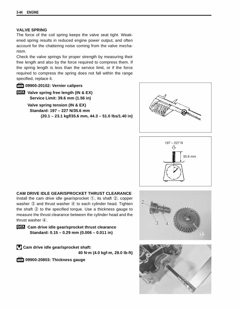
3-44 ENGINE
VALVE SPRINGThe force of the coil spring keeps the valve seat tight. Weak-ened spring results in reduced engine power output, and oftenaccount for the chattering noise coming from the valve mecha-nism.Check the valve springs for proper strength by measuring theirfree length and also by the force required to compress them. Ifthe spring length is less than the service limit, or if the forcerequired to compress the spring does not fall within the rangespecified, replace it.
09900-20102: Vernier calipers
Valve spring free length (IN & EX) Service Limit: 39.6 mm (1.56 in)
Valve spring tension (IN & EX)Standard: 197 – 227 N/35.6 mm
(20.1 – 23.1 kgf/35.6 mm, 44.3 – 51.0 lbs/1.40 in)
CAM DRIVE IDLE GEAR/SPROCKET THRUST CLEARANCEInstall the cam drive idle gear/sprocket
, its shaft
, copperwasher
and thrust washer
to each cylinder head. Tightenthe shaft
to the specified torque. Use a thickness gauge tomeasure the thrust clearance between the cylinder head and thethrust washer
.
Cam drive idle gear/sprocket thrust clearanceStandard: 0.15 – 0.29 mm (0.006 – 0.011 in)
Cam drive idle gear/sprocket shaft:40 N·m (4.0 kgf-m, 29.0 lb-ft)
09900-20803: Thickness gauge
197 – 227 N
35.6 mm
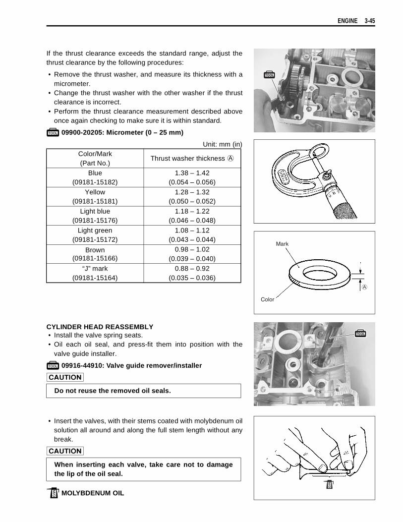
ENGINE 3-45
If the thrust clearance exceeds the standard range, adjust thethrust clearance by the following procedures:
• Remove the thrust washer, and measure its thickness with amicrometer.
• Change the thrust washer with the other washer if the thrustclearance is incorrect.
• Perform the thrust clearance measurement described aboveonce again checking to make sure it is within standard.
09900-20205: Micrometer (0 – 25 mm)
Unit: mm (in)
CYLINDER HEAD REASSEMBLY• Install the valve spring seats.• Oil each oil seal, and press-fit them into position with the
valve guide installer.
09916-44910: Valve guide remover/installer
• Insert the valves, with their stems coated with molybdenum oilsolution all around and along the full stem length without anybreak.
MOLYBDENUM OIL
Color/Mark(Part No.)
Thrust washer thickness
Blue(09181-15182)
1.38 – 1.42(0.054 – 0.056)
Yellow(09181-15181)
1.28 – 1.32(0.050 – 0.052)
Light blue(09181-15176)
1.18 – 1.22(0.046 – 0.048)
Light green(09181-15172)
1.08 – 1.12(0.043 – 0.044)
Brown(09181-15166)
0.98 – 1.02(0.039 – 0.040)
“J” mark(09181-15164)
0.88 – 0.92(0.035 – 0.036)
Mark
Color
Do not reuse the removed oil seals.
When inserting each valve, take care not to damagethe lip of the oil seal.

3-46 ENGINE
• Install the valve spring with the small-pitch portion
facingcylinder head.
: Large-pitch portion
• Put on the valve spring retainer, and using the valve lifter,press down the spring, fit the cotter halves to the stem end,and release the lifter to allow the cotter
to wedge inbetween retainer and stem. Be sure that the rounded lip
ofthe cotter fits snugly into the groove
in the stem end.
09916-14510: Valve lifter09916-14910: Valve lifter attachment09916-84511: Tweezers
• Install the tappet shim and tappet to their original position.
NOTE:* Apply engine oil to the shim and tappet before fitting them.* When seating the tappet shim, be sure the figure printed sur-
face faces the tappet.
INTAKE PIPE/WATER UNION• Remove the intake pipe.
UPWARD
Paint
Be sure to restore each spring and valve to their origi-nal positions.

ENGINE 3-47
• Remove the water union.
• When installing the intake pipe, apply grease to the O-ring.
NOTE:“UP” mark faces upward.
99000-25030: SUZUKI SUPER GREASE ‘‘A’’ (USA)99000-25010: SUZUKI SUPER GREASE ‘‘A’’ (Others)
• Apply engine coolant to the new O-ring and install the waterunion.
CYLINDER/PISTON INSPECTIONCYLINDER DISTORTIONCheck the gasketed surface of the cylinder for distortion with astraightedge and thickness gauge, taking a clearance reading atseveral places as indicated. If the largest reading at any positionof the straightedge exceeds the limit, replace the cylinder.
Cylinder distortionService Limit: 0.05 mm (0.002 in)
09900-20803: Thickness gauge
Use the new O-ring to prevent air from suckingthrough the joint.

3-48 ENGINE
CYLINDER BOREInspect the cylinder wall for any scratches, nicks or other dam-age. Measure the cylinder bore diameter at six places.
Cylinder boreStandard: 98.000 – 98.015 mm (3.8583 – 3.8589 in)
09900-20508: Cylinder gauge set
PISTON DIAMETERUsing a micrometer, measure the piston outside diameter at10 mm (0.4 in) from the piston skirt end. If the measurementis less than the limit, replace the piston.
Piston diameterService Limit: 97.880 mm (3.8535 in)
09900-20204: Micrometer (75 – 100 mm)
PISTON-TO-CYLINDER CLEARANCEAs a result of the previous measurement, if the piston to cylinderclearance exceeds the following limit, replace both cylinder andpiston.
Piston to cylinder clearanceService Limit: 0.12 mm (0.0047 in)
10 mm
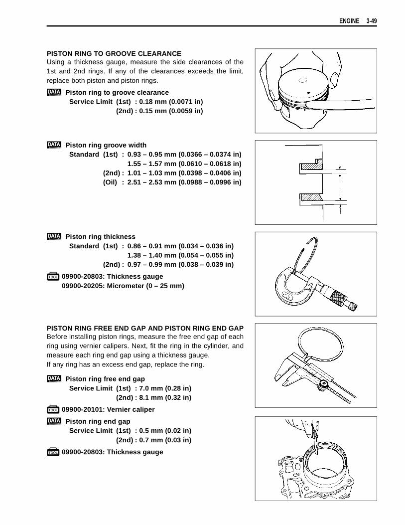
ENGINE 3-49
PISTON RING TO GROOVE CLEARANCEUsing a thickness gauge, measure the side clearances of the1st and 2nd rings. If any of the clearances exceeds the limit,replace both piston and piston rings.
Piston ring to groove clearanceService Limit (1st) : 0.18 mm (0.0071 in)
(2nd) : 0.15 mm (0.0059 in)
Piston ring groove widthStandard (1st) : 0.93 – 0.95 mm (0.0366 – 0.0374 in)
1.55 – 1.57 mm (0.0610 – 0.0618 in)(2nd) : 1.01 – 1.03 mm (0.0398 – 0.0406 in)(Oil) : 2.51 – 2.53 mm (0.0988 – 0.0996 in)
Piston ring thicknessStandard (1st) : 0.86 – 0.91 mm (0.034 – 0.036 in)
1.38 – 1.40 mm (0.054 – 0.055 in)(2nd) : 0.97 – 0.99 mm (0.038 – 0.039 in)
09900-20803: Thickness gauge09900-20205: Micrometer (0 – 25 mm)
PISTON RING FREE END GAP AND PISTON RING END GAPBefore installing piston rings, measure the free end gap of eachring using vernier calipers. Next, fit the ring in the cylinder, andmeasure each ring end gap using a thickness gauge.If any ring has an excess end gap, replace the ring.
Piston ring free end gapService Limit (1st) : 7.0 mm (0.28 in)
(2nd) : 8.1 mm (0.32 in)
09900-20101: Vernier caliper
Piston ring end gapService Limit (1st) : 0.5 mm (0.02 in)
(2nd) : 0.7 mm (0.03 in)
09900-20803: Thickness gauge
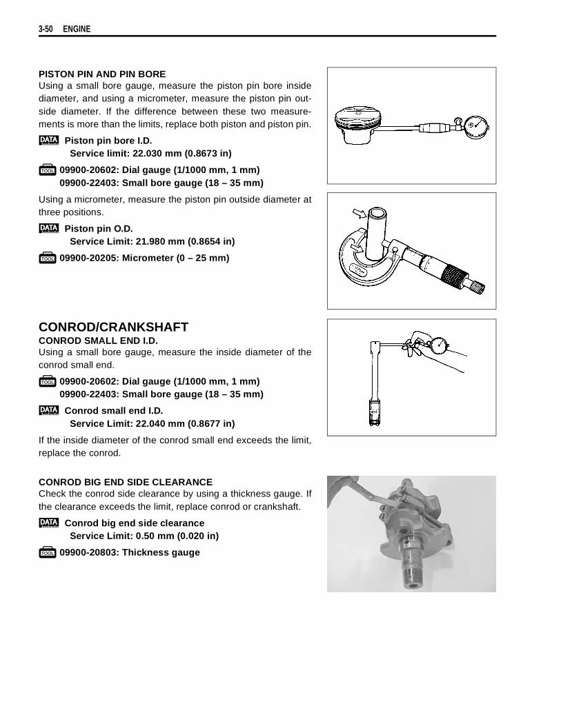
3-50 ENGINE
PISTON PIN AND PIN BOREUsing a small bore gauge, measure the piston pin bore insidediameter, and using a micrometer, measure the piston pin out-side diameter. If the difference between these two measure-ments is more than the limits, replace both piston and piston pin.
Piston pin bore I.D.Service limit: 22.030 mm (0.8673 in)
09900-20602: Dial gauge (1/1000 mm, 1 mm)09900-22403: Small bore gauge (18 – 35 mm)
Using a micrometer, measure the piston pin outside diameter atthree positions.
Piston pin O.D.Service Limit: 21.980 mm (0.8654 in)
09900-20205: Micrometer (0 – 25 mm)
CONROD/CRANKSHAFTCONROD SMALL END I.D.Using a small bore gauge, measure the inside diameter of theconrod small end.
09900-20602: Dial gauge (1/1000 mm, 1 mm)09900-22403: Small bore gauge (18 – 35 mm)
Conrod small end I.D.Service Limit: 22.040 mm (0.8677 in)
If the inside diameter of the conrod small end exceeds the limit,replace the conrod.
CONROD BIG END SIDE CLEARANCECheck the conrod side clearance by using a thickness gauge. Ifthe clearance exceeds the limit, replace conrod or crankshaft.
Conrod big end side clearanceService Limit: 0.50 mm (0.020 in)
09900-20803: Thickness gauge

ENGINE 3-51
Conrod big end widthStandard: 21.95 – 22.00 mm (0.864 – 0.866 in)
Crank pin widthStandard: 44.17 – 44.22 mm (1.739 – 1.741 in)
09900-20205: Micrometer (0 – 25 mm)
CONROD-CRANK PIN BEARING INSPECTION• Loosen the bearing cap bolts, and tap the bearing cap bolt
lightly with plastic hammer to remove the bearing cap.
• Remove the conrods, and mark them to identify the cylinderposition.
• Inspect the bearing surfaces for any sign of fusion, pitting,burn, or flaws. If any, replace them with a specified set ofbearings.
CONROD-CRANK PIN BEARING SELECTION• Place plastigauge axially on the crank pin avoiding the oil
hole, at TDC or BDC side as shown.• Tighten the bearing cap bolts as the specified manner.
09900-22301: Plastigauge09900-22302: Plastigauge
NOTE:Never rotate the crankshaft or conrod when a piece of plasti-gauge is in the clearance.
Never reuse the bearing cap bolt.

3-52 ENGINE
• Remove the caps and measure the width of compressed plas-tigauge with envelope scale. This measurement should betaken at the widest part.
Conrod big end oil clearanceService Limit: 0.080 mm (0.0031 in)
• If oil clearance exceeds the service limit, select the specifiedbearings from the bearing selection table.
• Check the corresponding conrod I.D. code number
, “1” or“2”.
• Check the corresponding crank pin O.D. code number
, “1”,“2” or “3” stamped on the left crank web.
Bearing selection table
Conrod big end oil clearanceStandard: 0.040 – 0.064 mm (0.0016 – 0.0025 in)
Conrod big end I.D. specification
Crank pin O.D. specification
09900-20202: Micrometer (25 – 50 mm)
Crank pin O.D.
Code 1 2 3
Conrod I.D. code
1 Green Black Brown2 Black Brown Yellow
LH RH
FRONT
Code
I.D. specification
148.000 – 48.008 mm(1.8898 – 1.8900 in)
248.008 – 48.016 mm(1.8900 – 1.8904 in)
Code
O.D. specification
144.992 – 45.000 mm(1.7713 – 1.7717 in)
244.984 – 44.992 mm(1.7710 – 1.7713 in)
344.976 – 44.984 mm(1.7707 – 1.7710 in)

ENGINE 3-53
Bearing thickness
BEARING ASSEMBLY• When fitting the bearings to the bearing cap and conrod, be
sure to fix the stopper part
first, and press in the other end.
• Apply molybdenum oil solution to the crank pin and bearingsurface.
MOLYBDENUM OIL
Color (Part No.) ThicknessGreen
(12164-02F11-0A0)1.476 – 1.480 mm
(0.0581 – 0.0583 in)Black
(12164-02F11-0B0)1.480 – 1.484 mm
(0.0583 – 0.0584 in)Brown
(12164-02F11-0C0)1.484 – 1.488 mm
(0.0584 – 0.0586 in)Yellow
(12164-02F11-0D0)1.488 – 1.492 mm
(0.0586 – 0.0587 in)
Bearing must be replaced as a set.
Color code

3-54 ENGINE
• When fitting the conrods on the crankshaft, make sure thatI.D. codes
of the conrods face each cylinder intake valvesides.
Apply engine oil to the bearing cap bolts.• Tighten the bearing cap bolts as following two steps.
Conrod bearing cap bolt(Initial) : 35 N·m (3.5 kgf-m, 25.5 lb-ft)(Final) : After tightening the bolts to the above torque,
tighten them 1/4 of a turn (90°).
• Check the conrod movement for smooth turning.
CLUTCHCLUTCH DRIVE PLATES
NOTE:Wipe off engine oil from the clutch drive plates with a clean rag.
Measure the thickness of drive plates with a vernier calipers. Ifeach drive plate is not within the standard range, replace it witha new one.
Drive plate thicknessStandard (No.1): 2.92 – 3.08 mm (0.115 – 0.121 in)
(No.2 & No.3): 3.72 – 3.88 mm (0.146 – 0.153 in)09900-20102: Vernier calipers
Measure the claw width of drive plates with a vernier calipers.Replace the drive plates found to have worn down to the limit.
Drive plate claw width (No.1 and No.2)Standard (No.1): 13.85 – 13.96 mm (0.545 – 0.550 in)
(No.2 & No.3): 13.90 – 14.00 mm (0.547 – 0.551 in)09900-20102: Vernier calipers
Never reuse the bearing cap bolt.
1
35 N·m3.5 kgf-m25.5 lb-ft( )
35 N·m3.5 kgf-m25.5 lb-ft( )
90˚
90˚
Measuring thickness
Measuring claw width
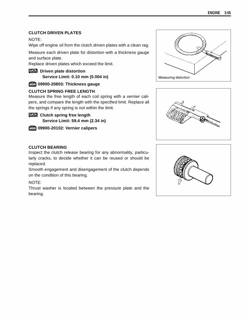
ENGINE 3-55
CLUTCH DRIVEN PLATES
NOTE:Wipe off engine oil from the clutch driven plates with a clean rag.
Measure each driven plate for distortion with a thickness gaugeand surface plate.Replace driven plates which exceed the limit.
Driven plate distortionService Limit: 0.10 mm (0.004 in)
09900-20803: Thickness gauge
CLUTCH SPRING FREE LENGTHMeasure the free length of each coil spring with a vernier cali-pers, and compare the length with the specified limit. Replace allthe springs if any spring is not within the limit.
Clutch spring free lengthService Limit: 59.4 mm (2.34 in)
09900-20102: Vernier calipers
CLUTCH BEARINGInspect the clutch release bearing for any abnormality, particu-larly cracks, to decide whether it can be reused or should bereplaced.Smooth engagement and disengagement of the clutch dependson the condition of this bearing.
NOTE:Thrust washer is located between the pressure plate and thebearing.
Measuring distortion

3-56 ENGINE
TRANSMISSIONCONSTRUCTION
1st driven gear5th driven gear4th driven gear3rd driven gear6th driven gear2nd driven gearDrive shaftCountershaft5th drive gear3rd & 4th drive gear6th drive gear2nd drive gear
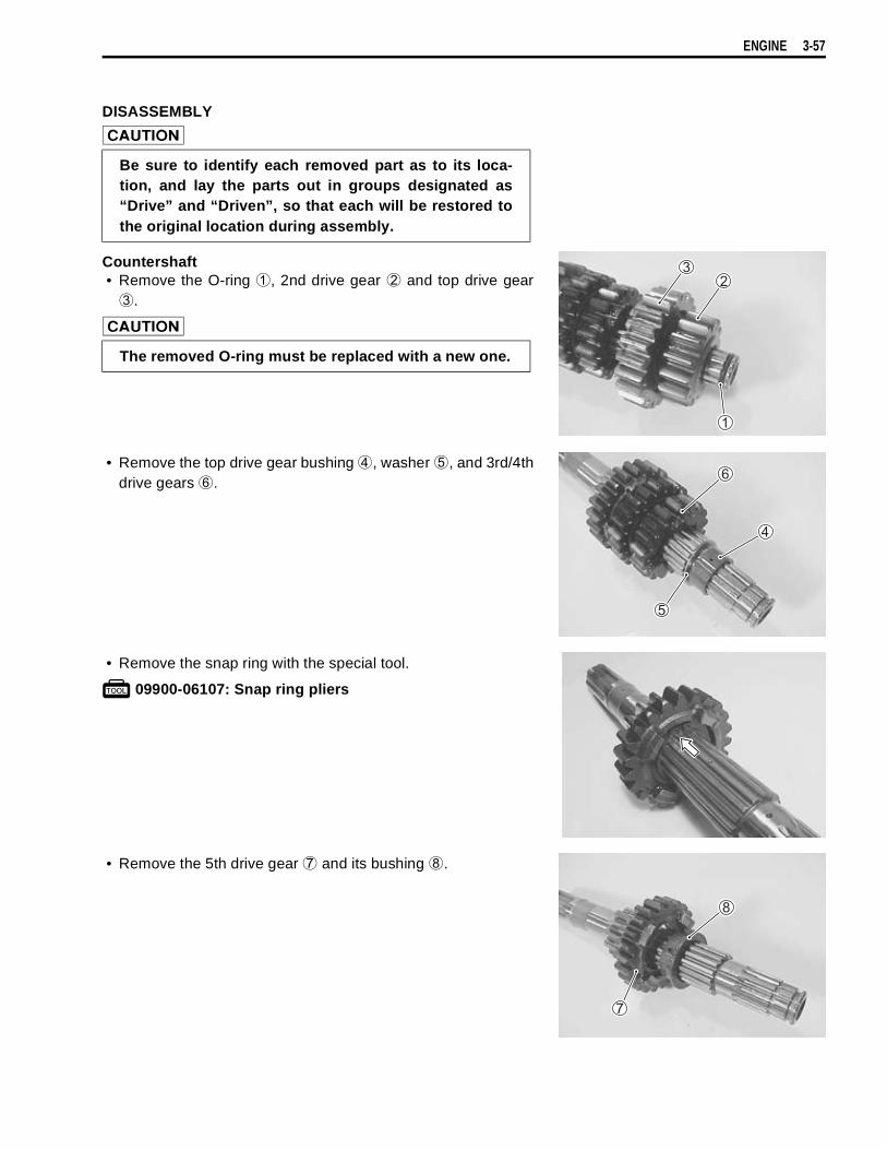
ENGINE 3-57
DISASSEMBLY
Countershaft• Remove the O-ring
, 2nd drive gear
and top drive gear
.
• Remove the top drive gear bushing
, washer
, and 3rd/4thdrive gears
.
• Remove the snap ring with the special tool.
09900-06107: Snap ring pliers
• Remove the 5th drive gear
and its bushing
.
Be sure to identify each removed part as to its loca-tion, and lay the parts out in groups designated as“Drive” and “Driven”, so that each will be restored tothe original location during assembly.
The removed O-ring must be replaced with a new one.
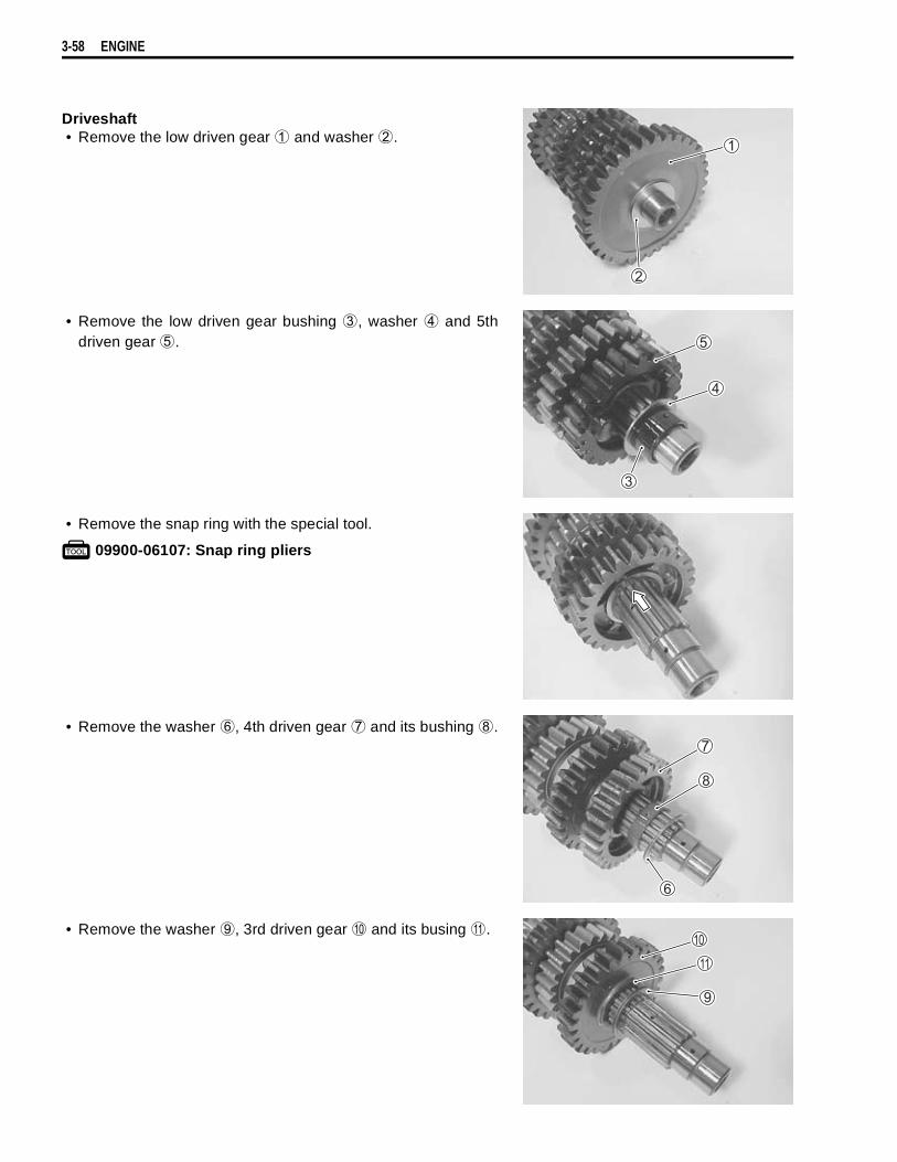
3-58 ENGINE
Driveshaft• Remove the low driven gear
and washer
.
• Remove the low driven gear bushing
, washer
and 5thdriven gear
.
• Remove the snap ring with the special tool.
09900-06107: Snap ring pliers
• Remove the washer
, 4th driven gear
and its bushing
.
• Remove the washer
, 3rd driven gear
and its busing
.

ENGINE 3-59
• Remove the washer
.• Remove the top driven gear
by removing the snap ring.
09900-06107: Snap ring pliers
• Remove the snap ring with the special tool.
09900-06107: Snap ring pliers
• Remove the 2nd driven gear
, its bushing
and washer
.
REASSEMBLYAssemble the transfer in the reverse order of disassembly. Payattention to the following points:
NOTE:* Always use new snap rings.* Before installing the gears, coat lightly engine oil to the shafts
and gears.
* Never reuse a snap ring. After a snap ring has beenremoved from a shaft, it should be discarded and anew snap ring must be installed.
* When installing a new snap ring, care must be takennot to expand the end gap larger than required to slipthe snap ring over the shaft.
* After installing a snap ring, always ensure that it iscompletely seated in its groove and securely fitted.

3-60 ENGINE
• When installing a new snap ring, pay attention to the directionof the snap ring. Fit it to the side where the thrust is as shownin the figure. Thrust
Sharp edge
When installing the 3rd and 4th driven gear bushingson to the driveshaft, align the shaft oil holes
withthe bushing oil hole
.
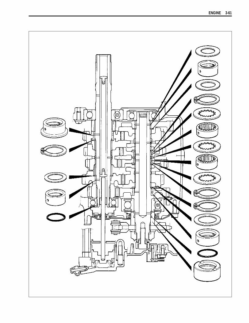
ENGINE 3-61

3-62 ENGINE
GEARSHIFT FORKGEARSHIFT FORK TO GROOVE CLEARANCEUsing a thickness gauge, check the gearshift fork clearance inthe groove of its gear.The clearance for each gearshift fork plays an important role inthe smoothness and positiveness of the shifting action.
Shift fork to groove clearanceService Limit: 0.50 mm (0.020 in)
09900-20803: Thickness gauge09900-20102: Vernier calipers
If the clearance checked is noted to exceed the limit specified,replace the fork or its gear, or both.
Shift fork groove widthStandard: 5.0 – 5.1 mm (0.197 – 0.201 in)
Shift fork thicknessStandard: 4.8 – 4.9 mm (0.189 – 0.193 in)
Checking clearance
Checking groove width
Checking thickness
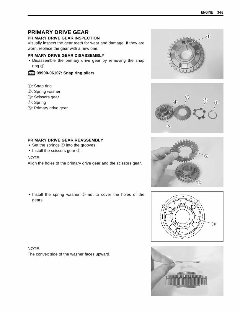
ENGINE 3-63
PRIMARY DRIVE GEARPRIMARY DRIVE GEAR INSPECTIONVisually inspect the gear teeth for wear and damage. If they areworn, replace the gear with a new one.
PRIMARY DRIVE GEAR DISASSEMBLY• Disassemble the primary drive gear by removing the snap
ring
.
09900-06107: Snap ring pliers
: Snap ring
: Spring washer
: Scissors gear
: Spring
: Primary drive gear
PRIMARY DRIVE GEAR REASSEMBLY• Set the springs
into the grooves.• Install the scissors gear
.
NOTE:Align the holes of the primary drive gear and the scissors gear.
• Install the spring washer
not to cover the holes of thegears.
NOTE:The convex side of the washer faces upward.

3-64 ENGINE
• Install the snap ring
completely with the special tool.
09900-06107: Snap ring pliers
STARTER TORQUE LIMITERSTARTER TORQUE LIMITER INSPECTION
• Check the slip torque with the special tools.
09930-73110: Starter torque limiter holder
09930-73120: Starter torque limiter socket
Slip torqueStandard: 20 – 45 N·m
(2.0 – 4.5 kgf-m, 14.5 – 32.5 lb-ft)
• Set the starter torque limiter to the special tools and vise asshown in the illustration.
• If the slip torque is not within the specification, replace thestarter torque limiter with a new one.
* Never reuse a snap ring.* When installing a new snap ring, care must be taken
not to expand the end gap larger than required to slipa snap ring over the gear.
* After installing a snap ring, always insure that it iscompletely seated in its groove and securely fitted.
Do not attempt to disassemble the starter torque lim-iter.The starter torque limiter is available only as anassembly.

ENGINE 3-65
STARTER CLUTCHDISASSEMBLY• Remove the starter clutch securing bolts by holding the rotor
with the special tool.
09930-44541: Rotor holder
REASSEMBLY• Install the starter clutch in the proper direction.
NOTE:* When installing the starter clutch onto the rotor, face the
flange side
of the one way clutch to the rotor.* The arrow mark
must face to the engine side.
• Apply engine oil to the starter clutch.
• Apply THREAD LOCK SUPER “1303” to the bolts, and thentighten them to the specified torque with the special tool.
Starter clutch bolt: 26 N·m (2.6 kgf-m, 19.0 lb-ft)
99000-32030: THREAD LOCK SUPER “1303”
09930-44541: Rotor holder
INSPECTION• Install the starter driven gear to the starter clutch.• Check that the starter driven gear turns in the opposite direc-
tion of the arrow mark
on the rotor while holding the gener-ator rotor. The gear never turns in the direction of the arrow.
• If there is anything unusual, replace the one way clutch.
Inspect the starter driven gear bushing for any damage.
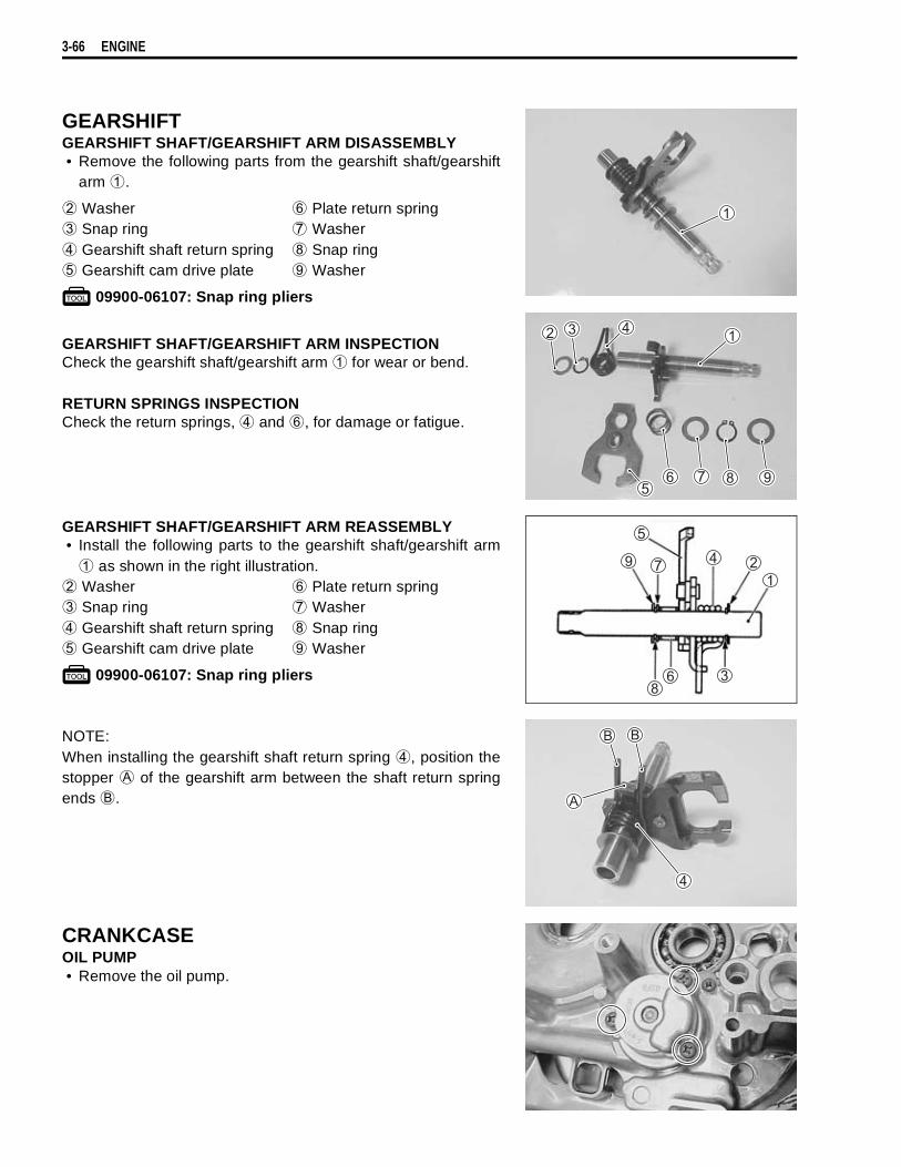
3-66 ENGINE
GEARSHIFTGEARSHIFT SHAFT/GEARSHIFT ARM DISASSEMBLY• Remove the following parts from the gearshift shaft/gearshift
arm
.
Washer
Plate return spring
Snap ring
Washer
Gearshift shaft return spring
Snap ring
Gearshift cam drive plate
Washer
09900-06107: Snap ring pliers
GEARSHIFT SHAFT/GEARSHIFT ARM INSPECTIONCheck the gearshift shaft/gearshift arm
for wear or bend.
RETURN SPRINGS INSPECTIONCheck the return springs,
and
, for damage or fatigue.
GEARSHIFT SHAFT/GEARSHIFT ARM REASSEMBLY• Install the following parts to the gearshift shaft/gearshift arm
as shown in the right illustration.
Washer
Plate return spring
Snap ring
Washer
Gearshift shaft return spring
Snap ring
Gearshift cam drive plate
Washer
09900-06107: Snap ring pliers
NOTE:When installing the gearshift shaft return spring
, position thestopper
of the gearshift arm between the shaft return springends
.
CRANKCASEOIL PUMP• Remove the oil pump.

ENGINE 3-67
• Rotate the oil pump by hand and check that it movessmoothly.
• If it does not move smoothly, replace the oil pump assembly.
OIL PRESSURE REGULATOR• Remove the oil pressure regulator
.• When installing the oil pressure regulator, apply engine oil to
the new O-ring.
Check the operation of the oil pressure regulator by pushing onthe piston with a proper bar. If the piston does not operate,replace the oil pressure regulator with a new one.
OIL PRESSURE SWITCH• Remove the oil pressure switch
.• When installing the oil pressure switch, apply SUZUKI BOND
“1215” to the thread.
Oil pressure switch: 14 N·m (1.4 kgf-m, 10.0 lb-ft)
99000-31110: SUZUKI BOND “1215”
OIL JET• Remove the oil gallery plug.
Do not attempt to disassemble the oil pump assembly.The oil pump is available only as an assembly.
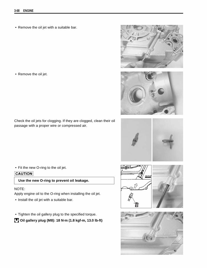
3-68 ENGINE
• Remove the oil jet with a suitable bar.
• Remove the oil jet.
Check the oil jets for clogging. If they are clogged, clean their oilpassage with a proper wire or compressed air.
• Fit the new O-ring to the oil jet.
NOTE:Apply engine oil to the O-ring when installing the oil jet.
• Install the oil jet with a suitable bar.
• Tighten the oil gallery plug to the specified torque.
Oil gallery plug (M8): 18 N·m (1.8 kgf-m, 13.0 lb-ft)
Use the new O-ring to prevent oil leakage.
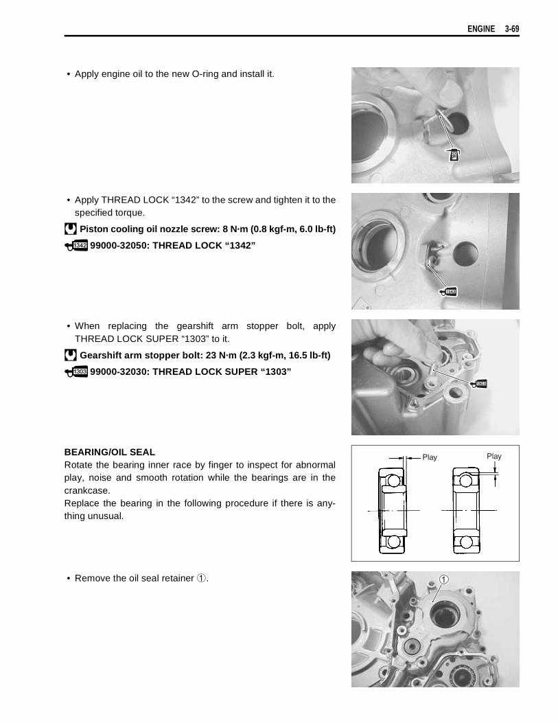
ENGINE 3-69
• Apply engine oil to the new O-ring and install it.
• Apply THREAD LOCK “1342” to the screw and tighten it to thespecified torque.
Piston cooling oil nozzle screw: 8 N·m (0.8 kgf-m, 6.0 lb-ft)
99000-32050: THREAD LOCK “1342”
• When replacing the gearshift arm stopper bolt, applyTHREAD LOCK SUPER “1303” to it.
Gearshift arm stopper bolt: 23 N·m (2.3 kgf-m, 16.5 lb-ft)
99000-32030: THREAD LOCK SUPER “1303”
BEARING/OIL SEALRotate the bearing inner race by finger to inspect for abnormalplay, noise and smooth rotation while the bearings are in thecrankcase.Replace the bearing in the following procedure if there is any-thing unusual.
• Remove the oil seal retainer
.
Play Play
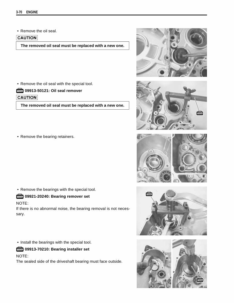
3-70 ENGINE
• Remove the oil seal.
• Remove the oil seal with the special tool.
09913-50121: Oil seal remover
• Remove the bearing retainers.
• Remove the bearings with the special tool.
09921-20240: Bearing remover set
NOTE:If there is no abnormal noise, the bearing removal is not neces-sary.
• Install the bearings with the special tool.
09913-70210: Bearing installer set
NOTE:The sealed side of the driveshaft bearing must face outside.
The removed oil seal must be replaced with a new one.
The removed oil seal must be replaced with a new one.

ENGINE 3-71
• Install the bearing retainers.
NOTE:When installing the bearing retainers, apply THREAD LOCK tothe screws.
09900-32050: THREAD LOCK “1342”
• Install the oil seals with the special tool.
09913-70210: Bearing installer set
• Install the oil seal retainer.
CRANKCASE-CRANKSHAFT BEARINGCRANKCASE-CRANKSHAFT BEARING INSPECTION• Inspect the crankshaft journal bearings for any damage. If
any, replace them with a specified set of bearings.
• Inspect the crankshaft journal for any damage.• Measure the crankshaft journal O.D. with the special tool.
Crankshaft journal O.D.Standard: 47.985 – 48.000 mm (1.8892 – 1.8898 in)
09900-20202: Micrometer (25 – 50 mm)
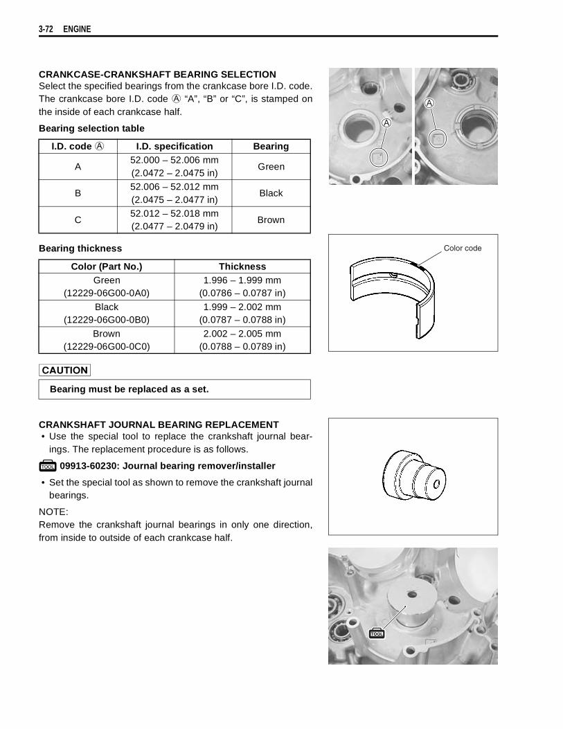
3-72 ENGINE
CRANKCASE-CRANKSHAFT BEARING SELECTIONSelect the specified bearings from the crankcase bore I.D. code.The crankcase bore I.D. code
“A”, “B” or “C”, is stamped onthe inside of each crankcase half.
Bearing selection table
Bearing thickness
CRANKSHAFT JOURNAL BEARING REPLACEMENT• Use the special tool to replace the crankshaft journal bear-
ings. The replacement procedure is as follows.
09913-60230: Journal bearing remover/installer
• Set the special tool as shown to remove the crankshaft journalbearings.
NOTE:Remove the crankshaft journal bearings in only one direction,from inside to outside of each crankcase half.
I.D. code
I.D. specification Bearing
A52.000 – 52.006 mm(2.0472 – 2.0475 in)
Green
B52.006 – 52.012 mm(2.0475 – 2.0477 in)
Black
C52.012 – 52.018 mm(2.0477 – 2.0479 in)
Brown
Color (Part No.) ThicknessGreen
(12229-06G00-0A0)1.996 – 1.999 mm
(0.0786 – 0.0787 in)
Black(12229-06G00-0B0)
1.999 – 2.002 mm(0.0787 – 0.0788 in)
Brown(12229-06G00-0C0)
2.002 – 2.005 mm(0.0788 – 0.0789 in)
Bearing must be replaced as a set.
Color code
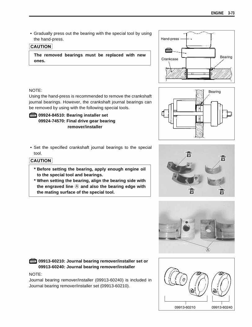
ENGINE 3-73
• Gradually press out the bearing with the special tool by usingthe hand-press.
NOTE:Using the hand-press is recommended to remove the crankshaftjournal bearings. However, the crankshaft journal bearings canbe removed by using with the following special tools.
09924-84510: Bearing installer set09924-74570: Final drive gear bearing
remover/installer
• Set the specified crankshaft journal bearings to the specialtool.
09913-60210: Journal bearing remover/installer set or09913-60240: Journal bearing remover/installer
NOTE:Journal bearing remover/installer (09913-60240) is included inJournal bearing remover/installer set (09913-60210).
The removed bearings must be replaced with newones.
Hand-press
CrankcaseBearing
Bearing
* Before setting the bearing, apply enough engine oilto the special tool and bearings.
* When setting the bearing, align the bearing side withthe engraved line
and also the bearing edge withthe mating surface of the special tool.
09913-60210 09913-60240
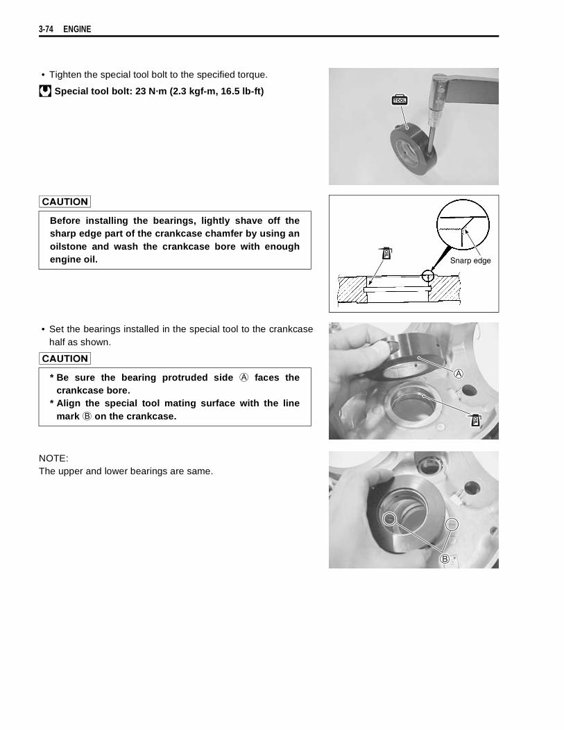
3-74 ENGINE
• Tighten the special tool bolt to the specified torque.
Special tool bolt: 23 N·m (2.3 kgf-m, 16.5 lb-ft)
• Set the bearings installed in the special tool to the crankcasehalf as shown.
NOTE:The upper and lower bearings are same.
Before installing the bearings, lightly shave off thesharp edge part of the crankcase chamfer by using anoilstone and wash the crankcase bore with enoughengine oil. Snarp edge
* Be sure the bearing protruded side
faces thecrankcase bore.
* Align the special tool mating surface with the linemark
on the crankcase.

ENGINE 3-75
• Apply enough engine oil to the special tool and the bearingsand then set the special tool carefully.
• Gradually press in the bearing into the main journal bore byusing the hand-press until the special tool
stops the specialtool
.
09913-60230: Journal bearing remover/installer
NOTE:Using the hand-press is recommended to install the crankshaftjournal bearings. However, the crankshaft journal bearings canbe installed by using the following special tools.
09924-84510: Bearing installer set09924-74570: Final drive gear bearing
remover/installer
Hand-press
Bearing
Bearing
Use the new special tool
(09913-60230) for DL1000.The tool
and
differ in length
.
For DL1000(09913-60230)
For TL1000S/R(09913-60210)
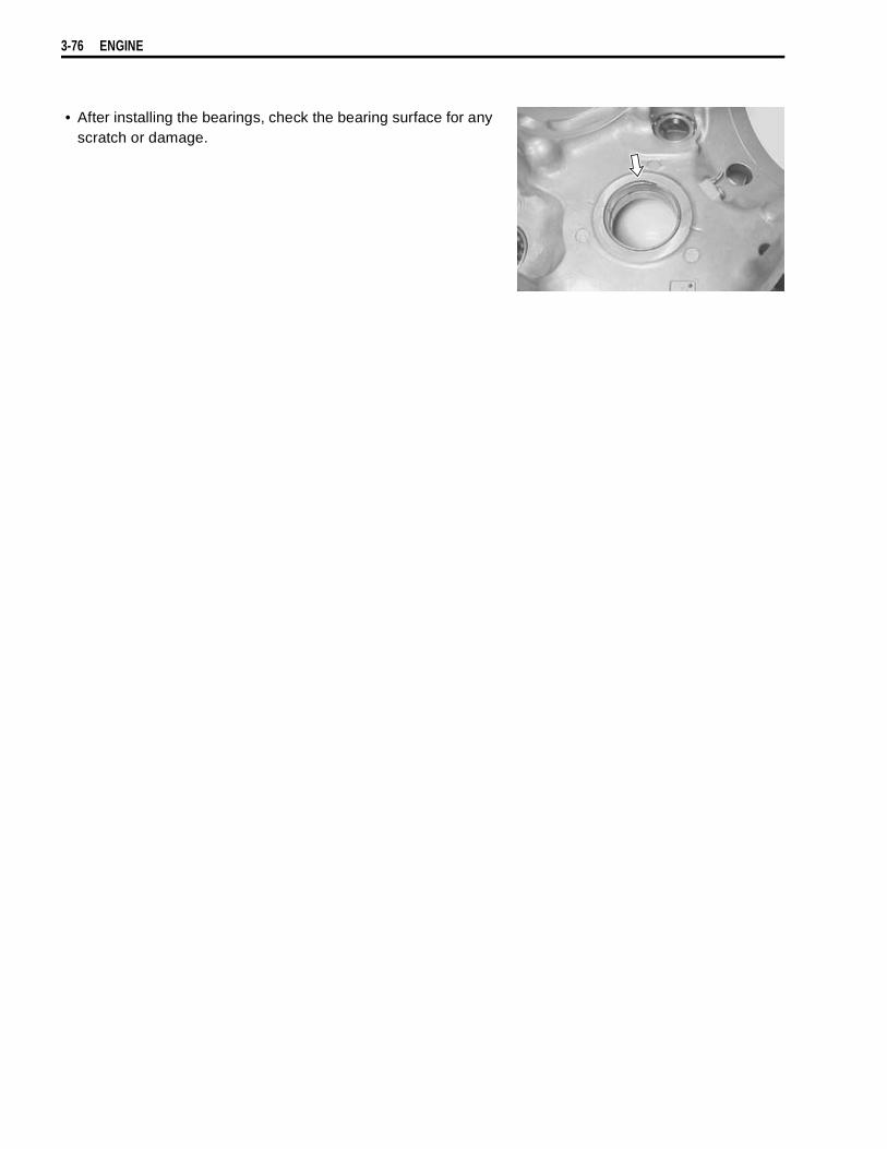
3-76 ENGINE
• After installing the bearings, check the bearing surface for anyscratch or damage.

ENGINE 3-77
GENERATOR COVERREPLACEMENTWhen replacing the generator stator or crankshaft position sen-sor, apply THREAD LOCK “1342” to the generator stator setbolts.
99000-32050: THREAD LOCK ‘‘1342’’
CLUTCH COVEROIL SEPARATER• Remove the oil separater
.
GEARSHIFT COVEROIL SEAL INSPECTIONInspect the gearshift shaft oil seal for damage or wear on the lip.If any defects are found, replace the oil seal with a new one.
OIL SEAL REPLACEMENT• Remove the gearshift shaft oil seal.
.
• Install the new oil seal with the special tool.
09913-70210: Bearing installer set
NOTE:Apply grease to the oil seal lip to prevent damage when install-ing the gearshift cover.
99000-25030: SUZUKI SUPER GREASE “A” (USA)99000-25010: SUZUKI SUPER GREASE “A” (Others)
The removed oil seal must be replaced with a new one.
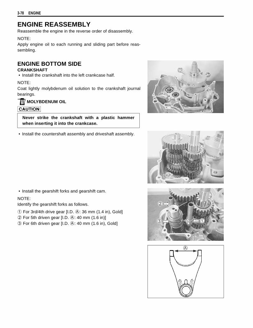
3-78 ENGINE
ENGINE REASSEMBLYReassemble the engine in the reverse order of disassembly.
NOTE:Apply engine oil to each running and sliding part before reas-sembling.
ENGINE BOTTOM SIDECRANKSHAFT• Install the crankshaft into the left crankcase half.
NOTE:Coat lightly molybdenum oil solution to the crankshaft journalbearings.
MOLYBDENUM OIL
• Install the countershaft assembly and driveshaft assembly.
• Install the gearshift forks and gearshift cam.
NOTE:Identify the gearshift forks as follows.
For 3rd/4th drive gear [I.D.
: 36 mm (1.4 in), Gold]
For 5th driven gear [I.D.
: 40 mm (1.6 in)]
For 6th driven gear [I.D.
: 40 mm (1.6 in), Gold]
Never strike the crankshaft with a plastic hammerwhen inserting it into the crankcase.

ENGINE 3-79
• Fit the dowel pins.
• Apply grease to the O-ring and install it.
99000-25030: SUZUKI SUPER GREASE “A” (USA)99000-25010: SUZUKI SUPER GREASE “A” (Others)
• Clean the mating surfaces of the left and right crankcasehalves.
• Apply SUZUKI BOND “1215” to the mating surface of the leftcrankcase.
99000-31110: SUZUKI BOND ‘‘1215’’
NOTE:Use of SUZUKI BOND “1215” is as follows:* Make surfaces free from moisture, oil, dust and other foreign materials.* Spread on surfaces thinly to form an even layer, and assemble the crankcases within few minutes.* Take extreme care not to apply any BOND “1215” to the oil hole, oil groove and bearing.* Apply to distorted surfaces as it forms a comparatively thick film.
Use the new O-ring to prevent oil leakage.
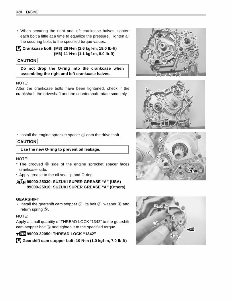
3-80 ENGINE
• When securing the right and left crankcase halves, tighteneach bolt a little at a time to equalize the pressure. Tighten allthe securing bolts to the specified torque values.
Crankcase bolt: (M8) 26 N·m (2.6 kgf-m, 19.0 lb-ft)(M6) 11 N·m (1.1 kgf-m, 8.0 lb-ft)
NOTE:After the crankcase bolts have been tightened, check if thecrankshaft, the driveshaft and the countershaft rotate smoothly.
• Install the engine sprocket spacer
onto the driveshaft.
NOTE:* The grooved
side of the engine sprocket spacer facescrankcase side.
* Apply grease to the oil seal lip and O-ring.
99000-25030: SUZUKI SUPER GREASE ‘‘A’’ (USA)99000-25010: SUZUKI SUPER GREASE ‘‘A’’ (Others)
GEARSHIFT• Install the gearshift cam stopper
, its bolt
, washer
andreturn spring
.
NOTE:Apply a small quantity of THREAD LOCK “1342” to the gearshiftcam stopper bolt
and tighten it to the specified torque.
99000-32050: THREAD LOCK ‘‘1342’’
Gearshift cam stopper bolt: 10 N·m (1.0 kgf-m, 7.0 lb-ft)
Do not drop the O-ring into the crankcase whenassembling the right and left crankcase halves.
Use the new O-ring to prevent oil leakage.
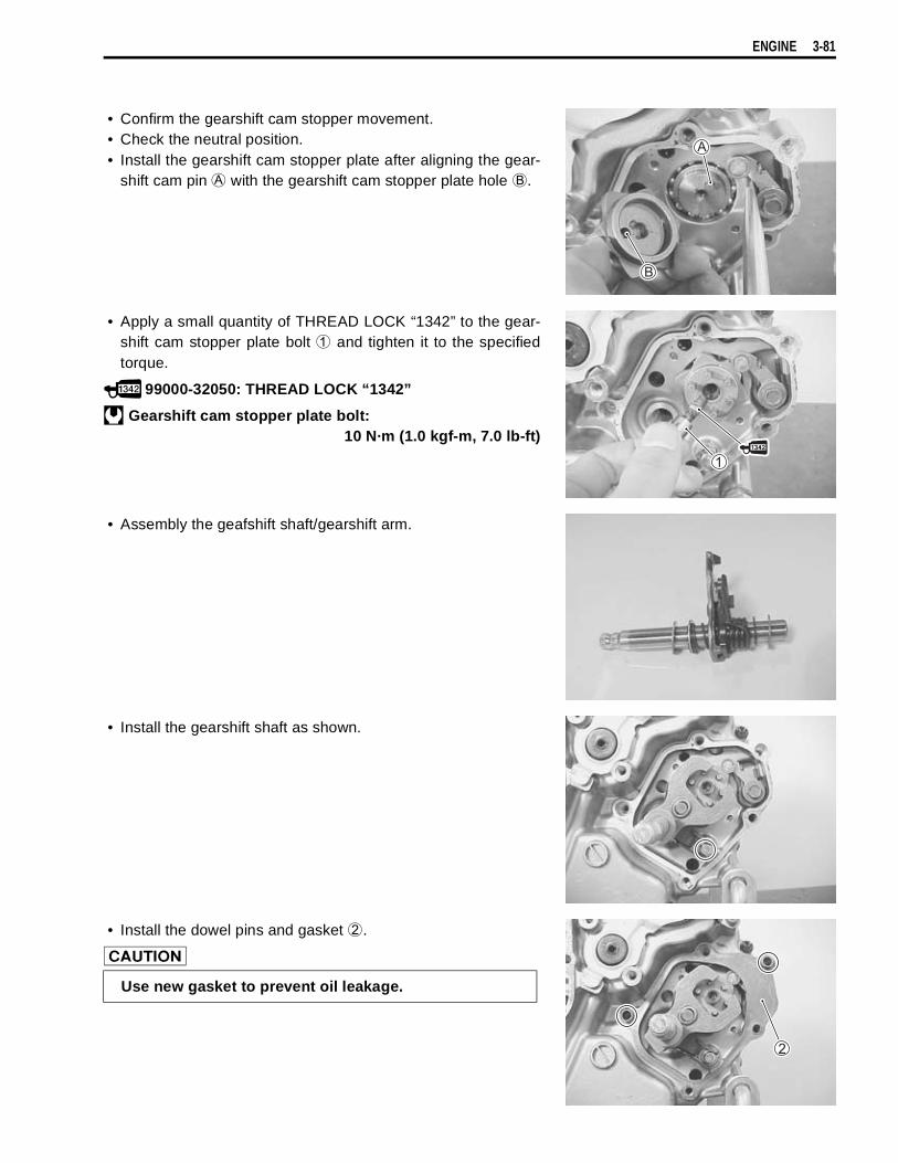
ENGINE 3-81
• Confirm the gearshift cam stopper movement.• Check the neutral position.• Install the gearshift cam stopper plate after aligning the gear-
shift cam pin
with the gearshift cam stopper plate hole
.
• Apply a small quantity of THREAD LOCK “1342” to the gear-shift cam stopper plate bolt
and tighten it to the specifiedtorque.
99000-32050: THREAD LOCK “1342”
Gearshift cam stopper plate bolt:10 N·m (1.0 kgf-m, 7.0 lb-ft)
• Assembly the geafshift shaft/gearshift arm.
• Install the gearshift shaft as shown.
• Install the dowel pins and gasket
.
Use new gasket to prevent oil leakage.
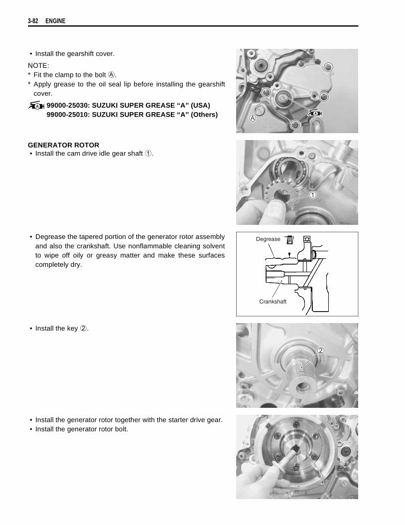
3-82 ENGINE
• Install the gearshift cover.
NOTE:* Fit the clamp to the bolt
.* Apply grease to the oil seal lip before installing the gearshift
cover.
99000-25030: SUZUKI SUPER GREASE ‘‘A’’ (USA)99000-25010: SUZUKI SUPER GREASE ‘‘A’’ (Others)
GENERATOR ROTOR• Install the cam drive idle gear shaft
.
• Degrease the tapered portion of the generator rotor assemblyand also the crankshaft. Use nonflammable cleaning solventto wipe off oily or greasy matter and make these surfacescompletely dry.
• Install the key
.
• Install the generator rotor together with the starter drive gear.• Install the generator rotor bolt.
Degrease
Crankshaft
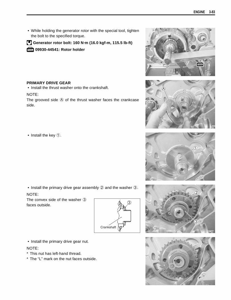
ENGINE 3-83
• While holding the generator rotor with the special tool, tightenthe bolt to the specified torque.
Generator rotor bolt: 160 N·m (16.0 kgf-m, 115.5 lb-ft)
09930-44541: Rotor holder
PRIMARY DRIVE GEAR• Install the thrust washer onto the crankshaft.
NOTE:The grooved side
of the thrust washer faces the crankcaseside.
• Install the key
.
• Install the primary drive gear assembly
and the washer
.
NOTE:The convex side of the washer
faces outside.
• Install the primary drive gear nut.
NOTE:* This nut has left-hand thread.* The “L” mark on the nut faces outside.
Crankshaft
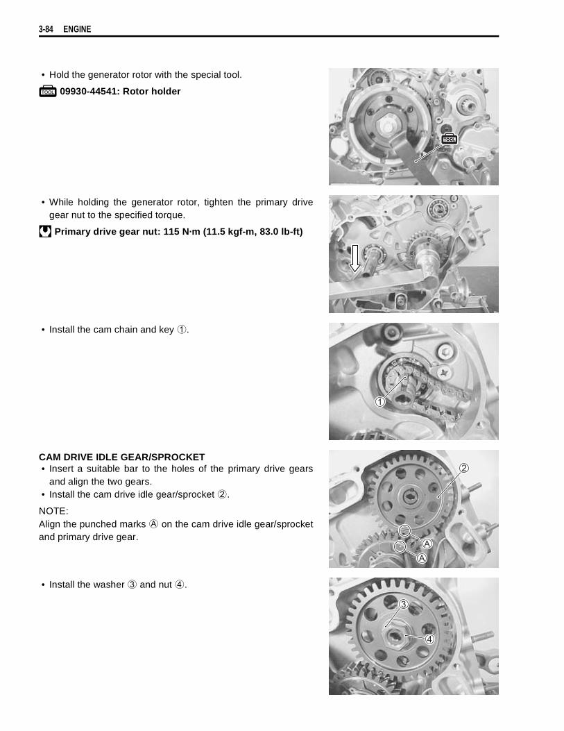
3-84 ENGINE
• Hold the generator rotor with the special tool.
09930-44541: Rotor holder
• While holding the generator rotor, tighten the primary drivegear nut to the specified torque.
Primary drive gear nut: 115 N·m (11.5 kgf-m, 83.0 lb-ft)
• Install the cam chain and key
.
CAM DRIVE IDLE GEAR/SPROCKET• Insert a suitable bar to the holes of the primary drive gears
and align the two gears.• Install the cam drive idle gear/sprocket
.
NOTE:Align the punched marks
on the cam drive idle gear/sprocketand primary drive gear.
• Install the washer
and nut
.
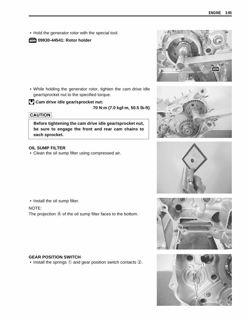
ENGINE 3-85
• Hold the generator rotor with the special tool.
09930-44541: Rotor holder
• While holding the generator rotor, tighten the cam drive idlegear/sprocket nut to the specified torque.
Cam drive idle gear/sprocket nut:70 N·m (7.0 kgf-m, 50.5 lb-ft)
OIL SUMP FILTER• Clean the oil sump filter using compressed air.
• Install the oil sump filter.
NOTE:The projection
of the oil sump filter faces to the bottom.
GEAR POSITION SWITCH• Install the springs
and gear position switch contacts
.
Before tightening the cam drive idle gear/sprocket nut,be sure to engage the front and rear cam chains toeach sprocket.
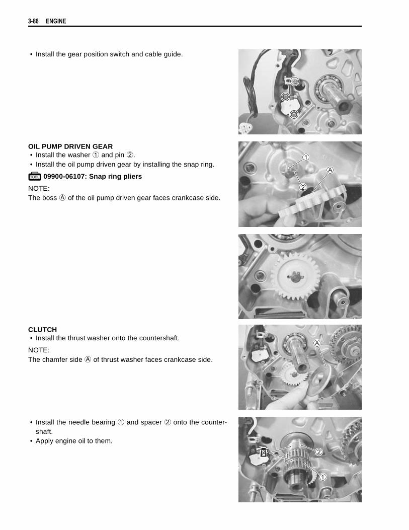
3-86 ENGINE
• Install the gear position switch and cable guide.
OIL PUMP DRIVEN GEAR• Install the washer
and pin
.• Install the oil pump driven gear by installing the snap ring.
09900-06107: Snap ring pliers
NOTE:The boss
of the oil pump driven gear faces crankcase side.
CLUTCH• Install the thrust washer onto the countershaft.
NOTE:The chamfer side
of thrust washer faces crankcase side.
• Install the needle bearing
and spacer
onto the counter-shaft.
• Apply engine oil to them.

ENGINE 3-87
• Install the primary driven gear assembly
onto the counter-shaft.
NOTE:* When installing the primary driven gear assembly, align the
teeth of the primary drive gears by inserting a suitable bar tothe holes of them.
* Be sure to engage the oil pump drive and driven gears, pri-mary drive and driven gears.
• Install the thrust washer
.
• Install the clutch sleeve hub.• Install the washer
,
and clutch sleeve hub nut.
NOTE:The convex side of the washer faces outside.
• Tighten the clutch sleeve hub nut to the specified torque withthe special tool.
Clutch sleeve hub nut: 150 N·m (15.0 kgf-m, 108.5 lb-ft)
09920-53740: Clutch sleeve hub holder
INSIDE
Washer
OUTSIDE
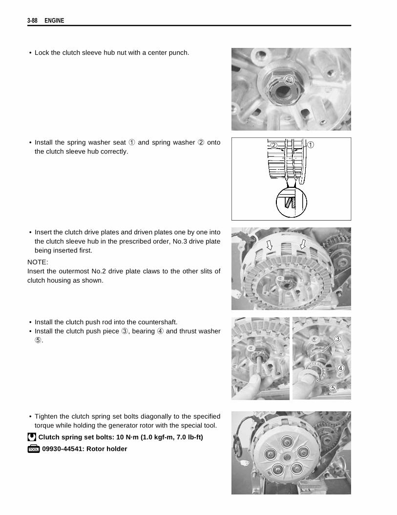
3-88 ENGINE
• Lock the clutch sleeve hub nut with a center punch.
• Install the spring washer seat
and spring washer
ontothe clutch sleeve hub correctly.
• Insert the clutch drive plates and driven plates one by one intothe clutch sleeve hub in the prescribed order, No.3 drive platebeing inserted first.
NOTE:Insert the outermost No.2 drive plate claws to the other slits ofclutch housing as shown.
• Install the clutch push rod into the countershaft.• Install the clutch push piece
, bearing
and thrust washer
.
• Tighten the clutch spring set bolts diagonally to the specifiedtorque while holding the generator rotor with the special tool.
Clutch spring set bolts: 10 N·m (1.0 kgf-m, 7.0 lb-ft)
09930-44541: Rotor holder
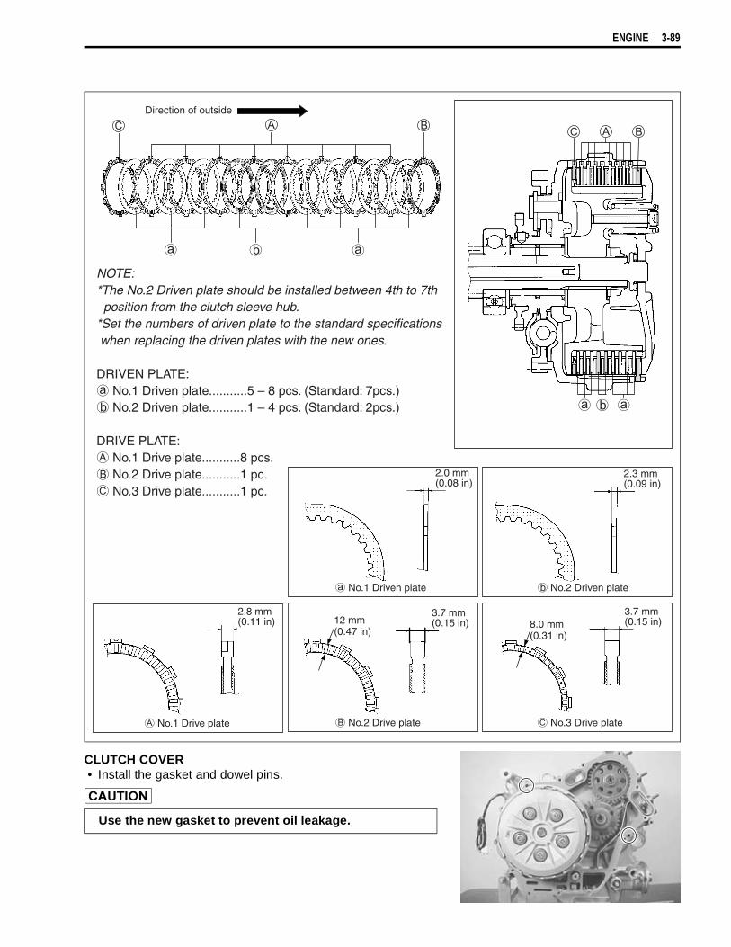
ENGINE 3-89
CLUTCH COVER• Install the gasket and dowel pins.
Direction of outside
NOTE:*The No.2 Driven plate should be installed between 4th to 7th position from the clutch sleeve hub.*Set the numbers of driven plate to the standard specifications when replacing the driven plates with the new ones.
DRIVEN PLATE: No.1 Driven plate...........5 – 8 pcs. (Standard: 7pcs.) No.2 Driven plate...........1 – 4 pcs. (Standard: 2pcs.)
DRIVE PLATE: No.1 Drive plate...........8 pcs. No.2 Drive plate...........1 pc. No.3 Drive plate...........1 pc.
2.0 mm(0.08 in)
2.3 mm(0.09 in)
2.8 mm(0.11 in)
3.7 mm(0.15 in)
3.7 mm(0.15 in)12 mm
(0.47 in)8.0 mm(0.31 in)
No.1 Driven plate No.2 Driven plate
No.3 Drive plate No.2 Drive plate No.1 Drive plate
Use the new gasket to prevent oil leakage.
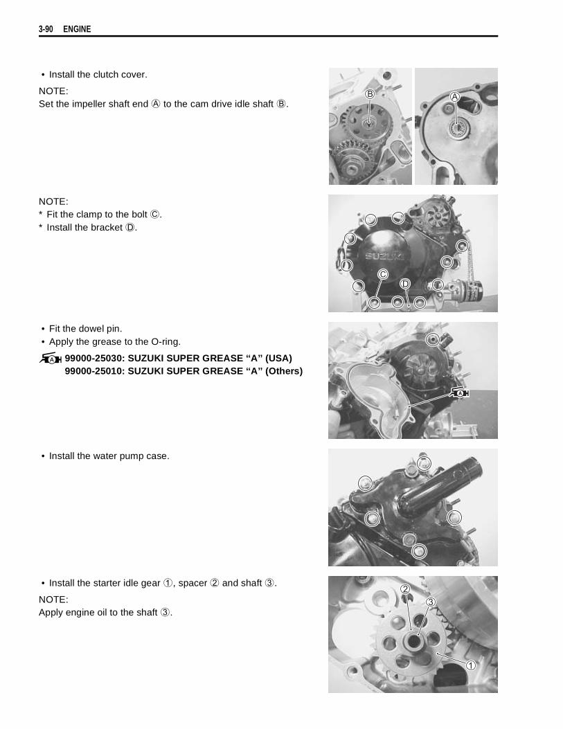
3-90 ENGINE
• Install the clutch cover.
NOTE:Set the impeller shaft end
to the cam drive idle shaft
.
NOTE:* Fit the clamp to the bolt
.* Install the bracket
.
• Fit the dowel pin.• Apply the grease to the O-ring.
99000-25030: SUZUKI SUPER GREASE ‘‘A’’ (USA)99000-25010: SUZUKI SUPER GREASE ‘‘A’’ (Others)
• Install the water pump case.
• Install the starter idle gear
, spacer
and shaft
.
NOTE:Apply engine oil to the shaft
.
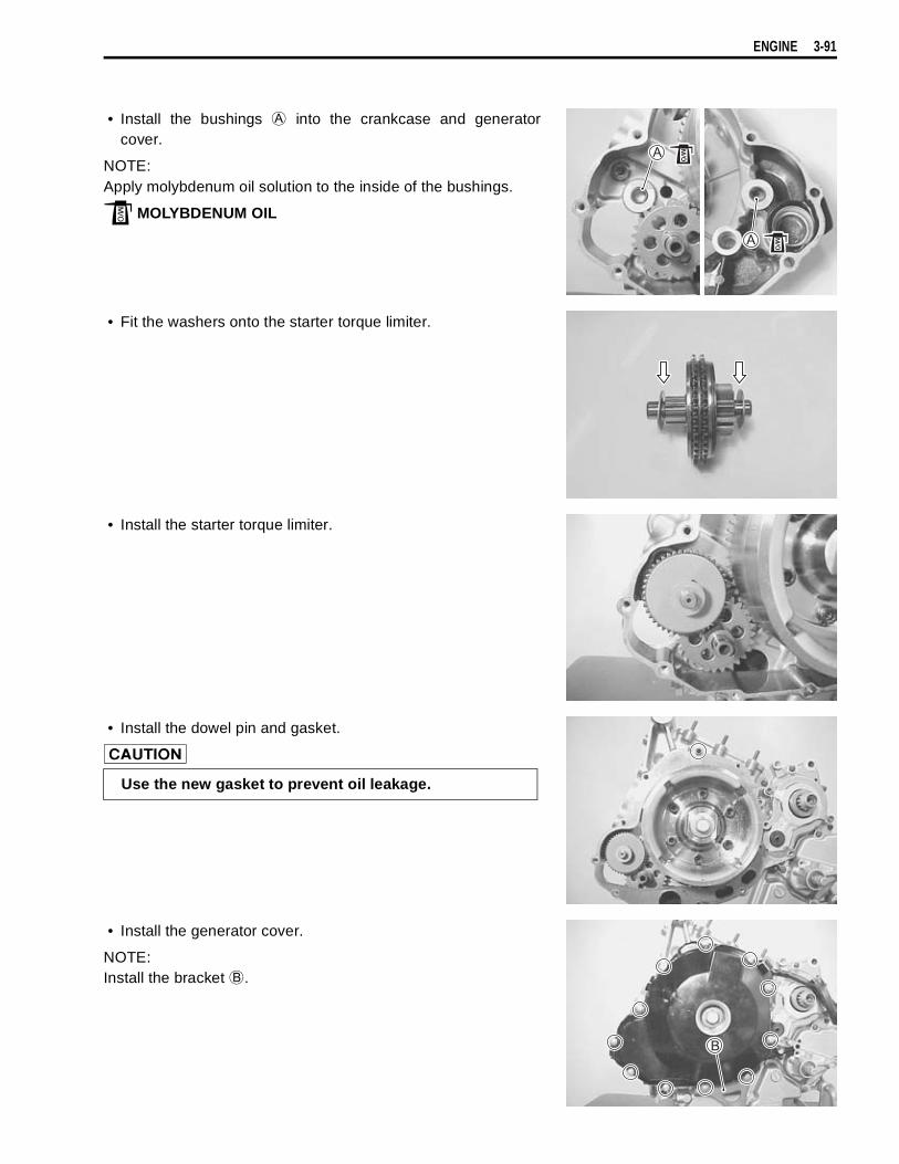
ENGINE 3-91
• Install the bushings
into the crankcase and generatorcover.
NOTE:Apply molybdenum oil solution to the inside of the bushings.
MOLYBDENUM OIL
• Fit the washers onto the starter torque limiter.
• Install the starter torque limiter.
• Install the dowel pin and gasket.
• Install the generator cover.
NOTE:Install the bracket
.
Use the new gasket to prevent oil leakage.
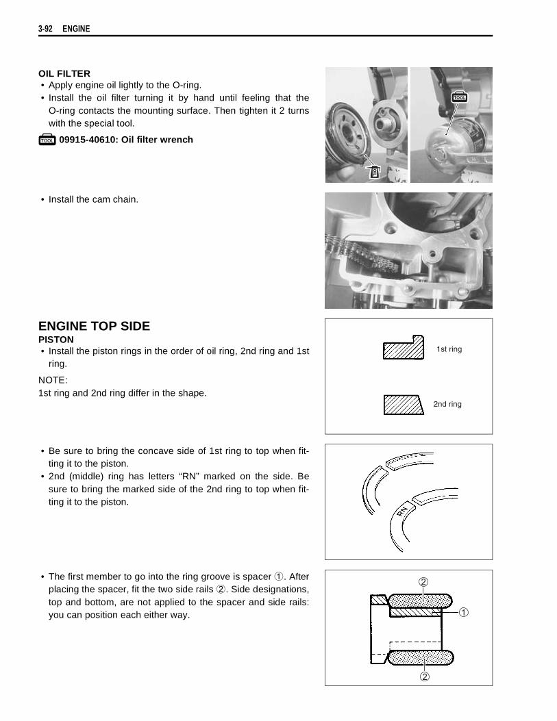
3-92 ENGINE
OIL FILTER• Apply engine oil lightly to the O-ring.• Install the oil filter turning it by hand until feeling that the
O-ring contacts the mounting surface. Then tighten it 2 turnswith the special tool.
09915-40610: Oil filter wrench
• Install the cam chain.
ENGINE TOP SIDEPISTON• Install the piston rings in the order of oil ring, 2nd ring and 1st
ring.
NOTE:1st ring and 2nd ring differ in the shape.
• Be sure to bring the concave side of 1st ring to top when fit-ting it to the piston.
• 2nd (middle) ring has letters “RN” marked on the side. Besure to bring the marked side of the 2nd ring to top when fit-ting it to the piston.
• The first member to go into the ring groove is spacer
. Afterplacing the spacer, fit the two side rails
. Side designations,top and bottom, are not applied to the spacer and side rails:you can position each either way.
1st ring
2nd ring
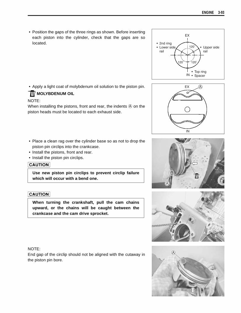
ENGINE 3-93
• Position the gaps of the three rings as shown. Before insertingeach piston into the cylinder, check that the gaps are solocated.
• Apply a light coat of molybdenum oil solution to the piston pin.
MOLYBDENUM OIL
NOTE:When installing the pistons, front and rear, the indents
on thepiston heads must be located to each exhaust side.
• Place a clean rag over the cylinder base so as not to drop thepiston pin circlips into the crankcase.
• Install the pistons, front and rear.• Install the piston pin circlips.
NOTE:End gap of the circlip should not be aligned with the cutaway inthe piston pin bore.
EX
IN
• 2nd ring• Lower side
rail• Upper side
rail
• Top ring• Spacer
120˚ 120˚
120˚
EX
IN
Use new piston pin circlips to prevent circlip failurewhich will occur with a bend one.
When turning the crankshaft, pull the cam chainsupward, or the chains will be caught between thecrankcase and the cam drive sprocket.

3-94 ENGINE
OIL JET• Apply engine oil to the new O-rings.• Install each of the oil jets.
CYLINDER• Coat SUZUKI BOND “1215” lightly to the mating surfaces at
the parting line between the right and left crankcases asshown.
NOTE:When replacing the stud bolt
, apply SUZUKI BOND “1215” tothe thread of the crankcase side.
99000-31110: SUZUKI BOND ‘‘1215’’
• Fit the dowel pins and new gaskets
to the crankcase.
• Apply engine oil to the sliding surface of the pistons and cylin-ders.
NOTE:The cylinders can be distinguished by the embossed-letters, “F”and “R”.“F”: Front (No.1) cylinder“R”: Rear (No.2) cylinder
Use the new O-rings to prevent oil leakage.
FRONT
Use the new gaskets to prevent oil leakage.
“R”
“L”
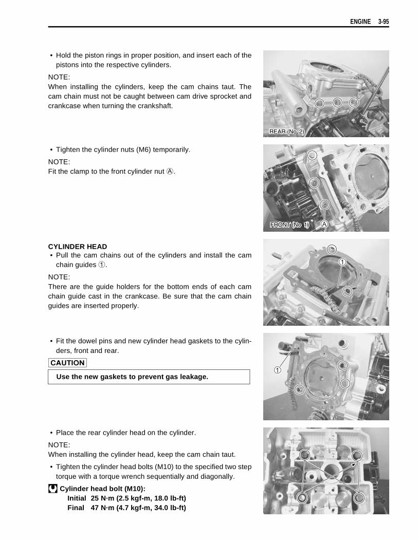
ENGINE 3-95
• Hold the piston rings in proper position, and insert each of thepistons into the respective cylinders.
NOTE:When installing the cylinders, keep the cam chains taut. Thecam chain must not be caught between cam drive sprocket andcrankcase when turning the crankshaft.
• Tighten the cylinder nuts (M6) temporarily.
NOTE:Fit the clamp to the front cylinder nut
.
CYLINDER HEAD• Pull the cam chains out of the cylinders and install the cam
chain guides
.
NOTE:There are the guide holders for the bottom ends of each camchain guide cast in the crankcase. Be sure that the cam chainguides are inserted properly.
• Fit the dowel pins and new cylinder head gaskets to the cylin-ders, front and rear.
• Place the rear cylinder head on the cylinder.
NOTE:When installing the cylinder head, keep the cam chain taut.
• Tighten the cylinder head bolts (M10) to the specified two steptorque with a torque wrench sequentially and diagonally.
Cylinder head bolt (M10):Initial 25 N·m (2.5 kgf-m, 18.0 lb-ft)Final 47 N·m (4.7 kgf-m, 34.0 lb-ft)
REAR (No. 2)
FRONT (No. 1)
Use the new gaskets to prevent gas leakage.
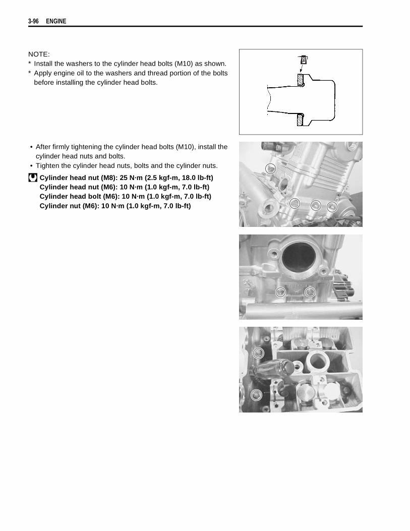
3-96 ENGINE
NOTE:* Install the washers to the cylinder head bolts (M10) as shown.* Apply engine oil to the washers and thread portion of the bolts
before installing the cylinder head bolts.
• After firmly tightening the cylinder head bolts (M10), install thecylinder head nuts and bolts.
• Tighten the cylinder head nuts, bolts and the cylinder nuts.
Cylinder head nut (M8): 25 N·m (2.5 kgf-m, 18.0 lb-ft)Cylinder head nut (M6): 10 N·m (1.0 kgf-m, 7.0 lb-ft)Cylinder head bolt (M6): 10 N·m (1.0 kgf-m, 7.0 lb-ft)Cylinder nut (M6): 10 N·m (1.0 kgf-m, 7.0 lb-ft)
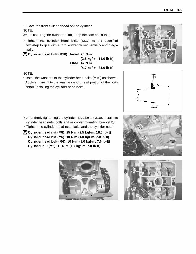
ENGINE 3-97
• Place the front cylinder head on the cylinder.NOTE:When installing the cylinder head, keep the cam chain taut.
• Tighten the cylinder head bolts (M10) to the specifiedtwo-step torque with a torque wrench sequentially and diago-nally.Cylinder head bolt (M10): Initial 25 N·m
(2.5 kgf-m, 18.0 lb-ft)Final 47 N·m
(4.7 kgf-m, 34.0 lb-ft)
NOTE:* Install the washers to the cylinder head bolts (M10) as shown.* Apply engine oil to the washers and thread portion of the bolts
before installing the cylinder head bolts.
• After firmly tightening the cylinder head bolts (M10), install thecylinder head nuts, bolts and oil cooler mounting bracket
.• Tighten the cylinder head nuts, bolts and the cylinder nuts.
Cylinder head nut (M8): 25 N·m (2.5 kgf-m, 18.0 lb-ft)Cylinder head nut (M6): 10 N·m (1.0 kgf-m, 7.0 lb-ft)Cylinder head bolt (M6): 10 N·m (1.0 kgf-m, 7.0 lb-ft)Cylinder nut (M6): 10 N·m (1.0 kgf-m, 7.0 lb-ft)

3-98 ENGINE
• Pull the cam chains upward and install the cam chain tension-ers into each cylinder head.
For No.1 (Front) cylinder head
For No.2 (Rear) cylinder head
NOTE:* When installing the cam chain tensioners, insert the their
holder ends
into each guide cast on the cylinder.* When installing the No.1 (Front) cam chain tensioner, through
it rear side of the rib
.
• Tighten the cam chain tensioner mounting bolts to the speci-fied torque.
Cam chain tensioner mounting bolt:10 N·m (1.0 kgf-m, 7.0 lb-ft)
FRONT
No. 1 (Front) cylinder
FRONT
No. 2 (Rear) cylinder
FRONT (No. 1)
REAR (No. 2)
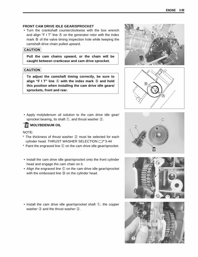
ENGINE 3-99
FRONT CAM DRIVE IDLE GEAR/SPROCKET• Turn the crankshaft counterclockwise with the box wrench
and align “F I T” line
on the generator rotor with the indexmark
of the valve timing inspection hole while keeping thecamshaft drive chain pulled upward.
• Apply molybdenum oil solution to the cam drive idle gear/sprocket bearing, its shaft
, and thrust washer
.
MOLYBDENUM OIL
NOTE:* The thickness of thrust washer
must be selected for eachcylinder head. THRUST WASHER SELECTION 3-44
* Paint the engraved line
on the cam drive idle gear/sprocket.
• Install the cam drive idle gear/sprocket onto the front cylinderhead and engage the cam chain on it.
• Align the engraved line
on the cam drive idle gear/sprocketwith the embossed line
on the cylinder head.
• Install the cam drive idle gear/sprocket shaft
, the copperwasher
and the thrust washer
.
Pull the cam chains upward, or the chain will becaught between crankcase and cam drive sprocket.
To adjust the camshaft timing correctly, be sure toalign “F I T” line
with the index mark
and holdthis position when installing the cam drive idle gears/sprockets, front and rear.

3-100 ENGINE
• Check and correct the positions of the “F I T” line on the gen-erator rotor and cam drive idle gear/sprocket
.
NOTE:Due to special valve train mechanism, aligning of the three ele-ments; the engraved line
, embossed line
and the geartooth root on the cam drive idle gear/sprocket; can occur onceevery other rotation of crankshaft.
When checking the positions, remove the cam chainslack at the cam chain guide
side by holding thecam drive idle gear/sprocket by hand.
INCORRECT CORRECT
If the engraved line
does not align the embossedline
, turn the crankshaft 360° (1 turn) to bring the“F I T” line on the generator rotor to the index mark ofthe valve timing inspection hole again and reinstall thecam drive idle gear/sprocket to the correct position asshown.
Root of tooth
CORRECT
Paint
Pull the cam chains upward, or the chain will becaught between crankcase and cam drive sprocketwhen turning the crankshaft.
Top of tooth
INCORRECT
Top of tooth
INCORRECT
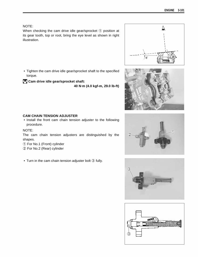
ENGINE 3-101
_
NOTE:When checking the cam drive idle gear/sprocket
position atits gear tooth, top or root, bring the eye level as shown in rightillustration.
• Tighten the cam drive idle gear/sprocket shaft to the specifiedtorque.
Cam drive idle gear/sprocket shaft:40 N·m (4.0 kgf-m, 29.0 lb-ft)
CAM CHAIN TENSION ADJUSTER• Install the front cam chain tension adjuster to the following
procedure.
NOTE:The cam chain tension adjusters are distinguished by theshapes.
For No.1 (Front) cylinder
For No.2 (Rear) cylinder
• Turn in the cam chain tension adjuster bolt
fully.
6˚
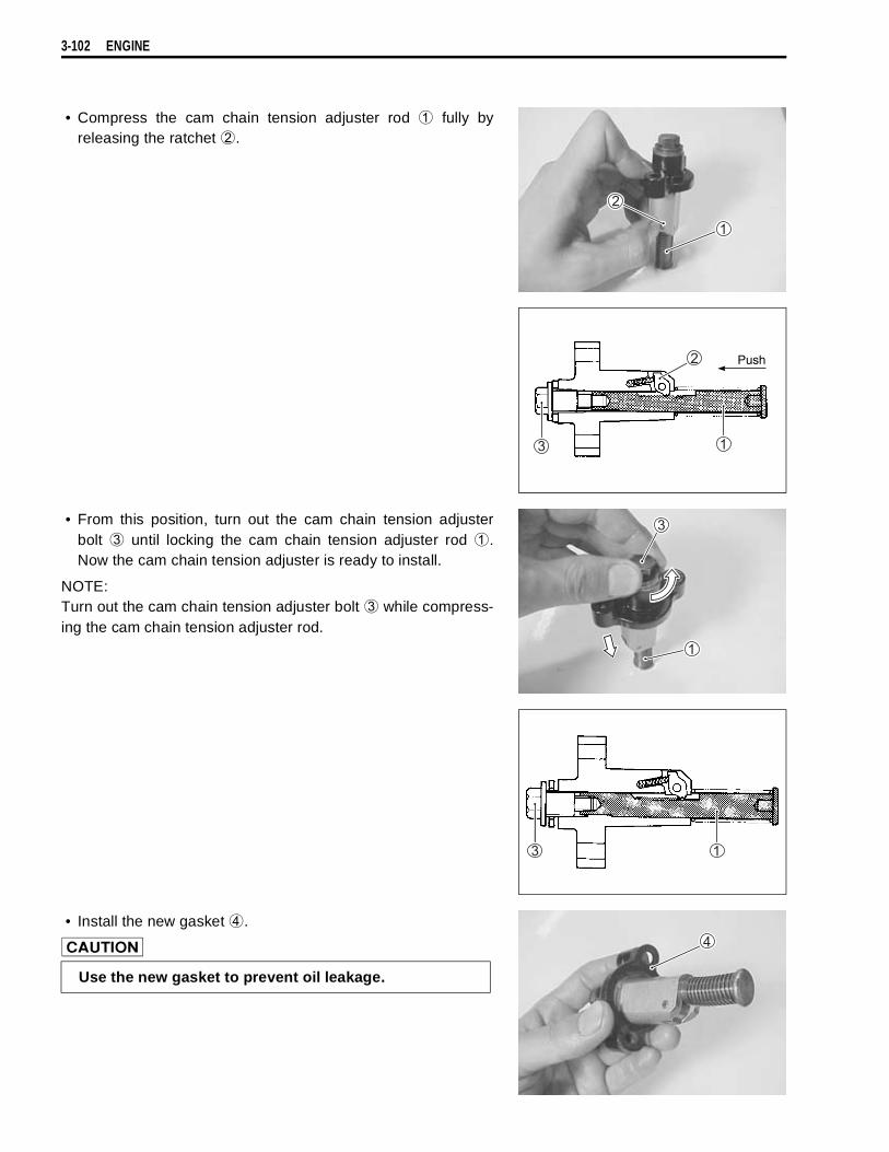
3-102 ENGINE
• Compress the cam chain tension adjuster rod
fully byreleasing the ratchet
.
• From this position, turn out the cam chain tension adjusterbolt
until locking the cam chain tension adjuster rod
.Now the cam chain tension adjuster is ready to install.
NOTE:Turn out the cam chain tension adjuster bolt
while compress-ing the cam chain tension adjuster rod.
• Install the new gasket
.
Push
Use the new gasket to prevent oil leakage.
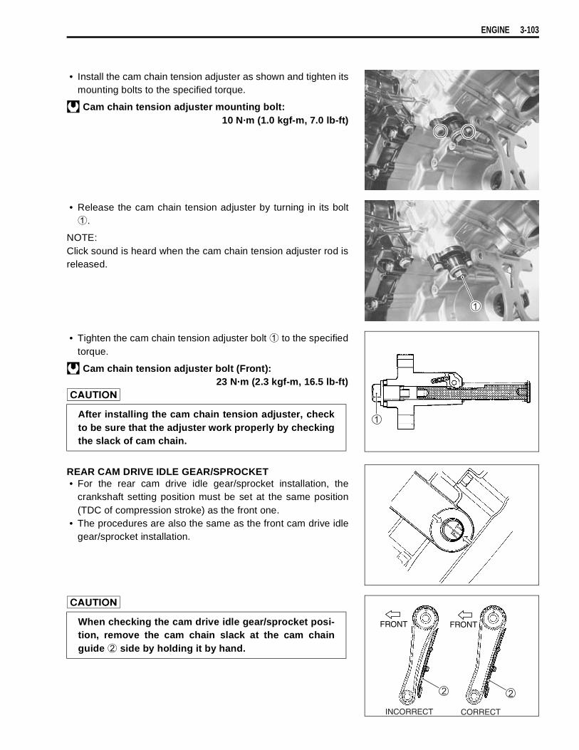
ENGINE 3-103
• Install the cam chain tension adjuster as shown and tighten itsmounting bolts to the specified torque.
Cam chain tension adjuster mounting bolt:10 N·m (1.0 kgf-m, 7.0 lb-ft)
• Release the cam chain tension adjuster by turning in its bolt
.
NOTE:Click sound is heard when the cam chain tension adjuster rod isreleased.
• Tighten the cam chain tension adjuster bolt
to the specifiedtorque.
Cam chain tension adjuster bolt (Front):23 N·m (2.3 kgf-m, 16.5 lb-ft)
REAR CAM DRIVE IDLE GEAR/SPROCKET• For the rear cam drive idle gear/sprocket installation, the
crankshaft setting position must be set at the same position(TDC of compression stroke) as the front one.
• The procedures are also the same as the front cam drive idlegear/sprocket installation.
After installing the cam chain tension adjuster, checkto be sure that the adjuster work properly by checkingthe slack of cam chain.
When checking the cam drive idle gear/sprocket posi-tion, remove the cam chain slack at the cam chainguide
side by holding it by hand.
INCORRECT CORRECT
FRONT FRONT
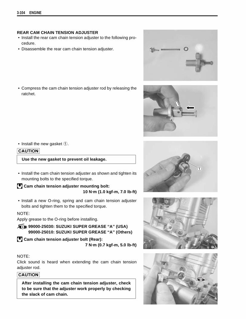
3-104 ENGINE
REAR CAM CHAIN TENSION ADJUSTER• Install the rear cam chain tension adjuster to the following pro-
cedure.• Disassemble the rear cam chain tension adjuster.
• Compress the cam chain tension adjuster rod by releasing theratchet.
• Install the new gasket
.
• Install the cam chain tension adjuster as shown and tighten itsmounting bolts to the specified torque.
Cam chain tension adjuster mounting bolt:10 N·m (1.0 kgf-m, 7.0 lb-ft)
• Install a new O-ring, spring and cam chain tension adjusterbolts and tighten them to the specified torque.
NOTE:Apply grease to the O-ring before installing.
99000-25030: SUZUKI SUPER GREASE ‘‘A’’ (USA)99000-25010: SUZUKI SUPER GREASE ‘‘A’’ (Others)
Cam chain tension adjuster bolt (Rear):7 N·m (0.7 kgf-m, 5.0 lb-ft)
NOTE:Click sound is heard when extending the cam chain tensionadjuster rod.
Use the new gasket to prevent oil leakage.
After installing the cam chain tension adjuster, checkto be sure that the adjuster work properly by checkingthe slack of cam chain.
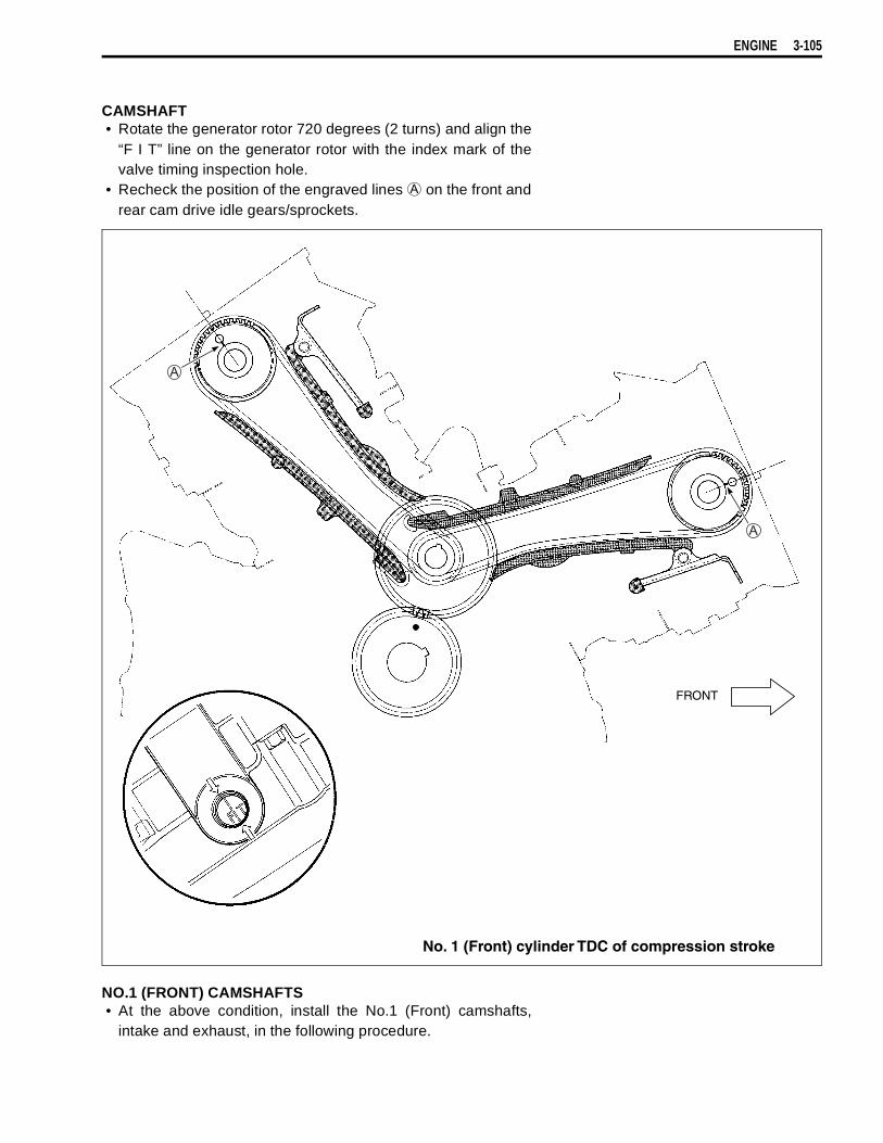
ENGINE 3-105
CAMSHAFT• Rotate the generator rotor 720 degrees (2 turns) and align the
“F I T” line on the generator rotor with the index mark of thevalve timing inspection hole.
• Recheck the position of the engraved lines
on the front andrear cam drive idle gears/sprockets.
NO.1 (FRONT) CAMSHAFTS• At the above condition, install the No.1 (Front) camshafts,
intake and exhaust, in the following procedure.
FRONT
No. 1 (Front) cylinder TDC of compression stroke
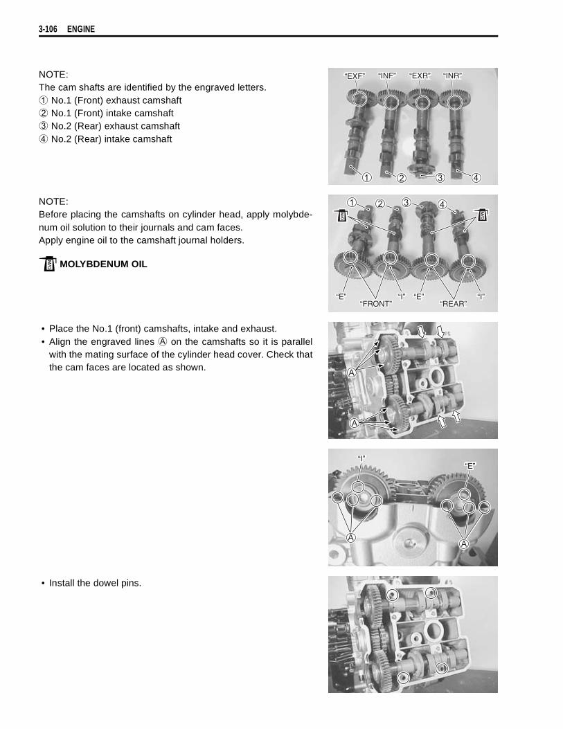
3-106 ENGINE
NOTE:The cam shafts are identified by the engraved letters.
No.1 (Front) exhaust camshaft
No.1 (Front) intake camshaft
No.2 (Rear) exhaust camshaft
No.2 (Rear) intake camshaft
NOTE:Before placing the camshafts on cylinder head, apply molybde-num oil solution to their journals and cam faces.Apply engine oil to the camshaft journal holders.
MOLYBDENUM OIL
• Place the No.1 (front) camshafts, intake and exhaust.• Align the engraved lines
on the camshafts so it is parallelwith the mating surface of the cylinder head cover. Check thatthe cam faces are located as shown.
• Install the dowel pins.
“EXF” “INF” “EXR” “INR”
“FRONT”“E” “E”“I” “I”
“REAR”
“I”“E”

ENGINE 3-107
• Install the camshaft journal holders, intake and exhaust.• Fasten the camshaft journal holders evenly by tightening the
camshaft journal holder bolts sequentially and diagonally. (Tryto equalize the pressure by shifting the wrench in the abovemanner, to fasten the shafts evenly.)
NOTE:* Damage to head or camshaft journal holder thrust surfaces
may result if the camshaft journal holders are not drawn downevenly.
* Each camshaft journal holder is identified with a cast-on letters
.
• Tighten the camshaft journal holder bolts to the specifiedtorque.
Camshaft journal holder bolt: 10 N·m (1.0 kgf-m, 7.0 lb-ft)
• Recheck the No.1 (Front) camshaft positions, intake andexhaust.
The camshaft journal holder bolts are made of a spe-cial material and much superior in strength, comparedwith other types of high strength bolts.Take special care not to use other types of boltsinstead of these special bolts. To identify these bolts,each of them has a figure “9” on its head.
IN
EX
“I”
“E”
Engraved line
Engraved line
No.1 (Front) cylinder head
FRONT

3-108 ENGINE
NO.2 (REAR) CAMSHAFTS• Install the No.2 (Rear) camshafts, intake and exhaust, in the
following procedure.• From the position where the No.1 (Front) camshafts have now
been installed, rotate the generator rotor 360 degrees (1 turn)and align the “F I T” line on the generator rotor with the indexmark of the valve timing inspection hole.
NOTE:At this position, the engraved line
on the cam drive idle gear/sprocket is inside the cylinder head and not visible.
• Place the No.2 (Rear) camshafts, intake
and exhaust
.• Align the engraved lines
on the camshafts so that it is par-allel with mating surface of the cylinder head cover. Checkthat the cam faces are located as shown.
• Install the dowel pins.
No. 2 (Rear) cylinder head
“I” “E”
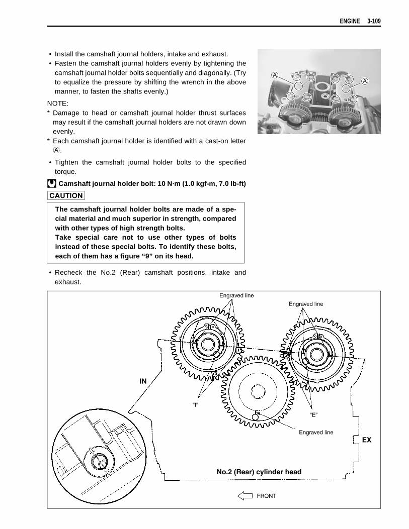
ENGINE 3-109
• Install the camshaft journal holders, intake and exhaust.• Fasten the camshaft journal holders evenly by tightening the
camshaft journal holder bolts sequentially and diagonally. (Tryto equalize the pressure by shifting the wrench in the abovemanner, to fasten the shafts evenly.)
NOTE:* Damage to head or camshaft journal holder thrust surfaces
may result if the camshaft journal holders are not drawn downevenly.
* Each camshaft journal holder is identified with a cast-on letter
.
• Tighten the camshaft journal holder bolts to the specifiedtorque.
Camshaft journal holder bolt: 10 N·m (1.0 kgf-m, 7.0 lb-ft)
• Recheck the No.2 (Rear) camshaft positions, intake andexhaust.
The camshaft journal holder bolts are made of a spe-cial material and much superior in strength, comparedwith other types of high strength bolts.Take special care not to use other types of boltsinstead of these special bolts. To identify these bolts,each of them has a figure “9” on its head.
IN
EX
“E”
Engraved line
No.2 (Rear) cylinder head
FRONT
“I”
Engraved line
Engraved line
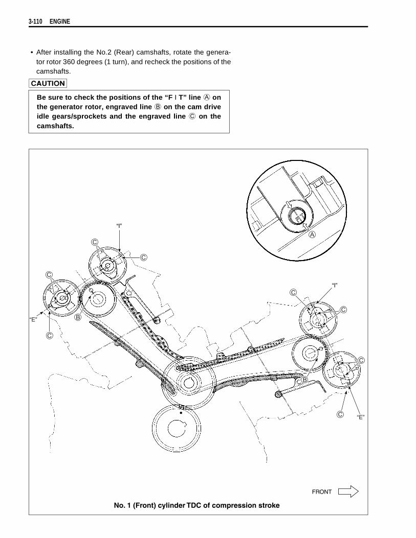
3-110 ENGINE
• After installing the No.2 (Rear) camshafts, rotate the genera-tor rotor 360 degrees (1 turn), and recheck the positions of thecamshafts.
Be sure to check the positions of the “F I T” line
onthe generator rotor, engraved line
on the cam driveidle gears/sprockets and the engraved line
on thecamshafts.
“I”
“E”
“I”
“E”
FRONT
No. 1 (Front) cylinder TDC of compression stroke

ENGINE 3-111
• Pour engine oil in each oil pocket in the front and rear cylinderheads.
CYLINDER HEAD COVER• Install the new gaskets (
,
) to each cylinder head cover.• Apply SUZUKI BOND “1207B” to the cam end caps of the
gaskets as shown.
99000-31140: SUZUKI BOND “1207B”
• Place the cylinder head covers on each cylinder head.• Fit the gaskets to each head cover bolt.
• After applying engine oil to the gaskets, tighten the headcover bolts to the specified torque.
Head cover bolt: 14 N·m (1.4 kgf-m, 10.0 lb-ft)
SPARK PLUG• Install the spark plugs.
09930-10121: Spark plug wrench set
• Install the valve timing inspection plug
.
Be sure to check the tappet clearance.
Use the new gaskets to prevent oil leakage.“FRONT” “REAR”
Use the new gaskets to prevent oil leakage.

3-112 ENGINE
• Apply engine oil to the new O-ring and install the generatorcover plug.
STARTER MOTOR• Install the new O-ring to the starter motor.
• Apply grease to the O-ring.
99000-25030: SUZUKI SUPER GREASE ‘‘A’’ (USA)99000-25010: SUZUKI SUPER GREASE ‘‘A’’ (Others)
• Install the starter motor.
NOTE:Fit the clamp to the bolt
.
• Install the thermostat case.
Use the new O-ring to prevent oil leakage.
Use the new O-ring to prevent oil leakage.


CONTENTS
FI SYSTEM
PRECAUTIONS IN SERVICING .....................................................................4- 2CONNECTOR/COUPLER ......................................................................4- 2FUSE ......................................................................................................4- 3ECM/VARIOUS SENSORS ....................................................................4- 3ELECTRICAL CIRCUIT INSPECTION PROCEDURE ..........................4- 5USING TESTERS ...................................................................................4- 8
FI SYSTEM TECHNICAL FEATURES ............................................................4- 9INJECTION TIME (INJECTION VOLUME) ............................................4- 9COMPENSATION OF INJECTION TIME (VOLUME) ............................4-10INJECTION STOP CONTROL ...............................................................4-10FUEL DELIVERY SYSTEM ...................................................................4-11FUEL PUMP ...........................................................................................4-12FUEL PRESSURE REGULATOR ..........................................................4-13FUEL INJECTOR ...................................................................................4-13FUEL PUMP CONTROL SYSTEM ........................................................4-14ECM (FI CONTROL UNIT) .....................................................................4-15INJECTION TIMING ...............................................................................4-15SENSORS ..............................................................................................4-16
FI SYSTEM PARTS LOCATION .....................................................................4-20FI SYSTEM WIRING DIAGRAM .....................................................................4-22SELF-DIAGNOSIS FUNCTION .......................................................................4-23
USER MODE ..........................................................................................4-23DEALER MODE .....................................................................................4-24TPS ADJUSTMENT ...............................................................................4-25
FAIL-SAFE FUNCTION ...................................................................................4-26FI SYSTEM TROUBLESHOOTING ................................................................4-27
CUSTOMER COMPLAINT ANALYSIS .................................................4-27SELF-DIAGNOSTIC PROCEDURES ....................................................4-29SELF-DIAGNOSIS RESET PROCEDURE ............................................4-29MALFUNCTION CODE AND DEFECTIVE CONDITION .......................4-30“C11” CMP SENSOR CIRCUIT MALFUNCTION .................................4-32“C12” CKP SENSOR CIRCUIT MALFUNCTION ..................................4-33“C13” IAP SENSOR CIRCUIT MALFUNCTION ...................................4-34“C14” TP SENSOR CIRCUIT MALFUNCTION .....................................4-36“C15” ECT SENSOR CIRCUIT MALFUNCTION ..................................4-38“C21” IAT SENSOR CIRCUIT MALFUNCTION ...................................4-39“C22” AP SENSOR CIRCUIT MALFUNCTION ....................................4-40“C23” TO SENSOR CIRCUIT MALFUNCTION ....................................4-42“C24” or “C25” IGNITION SYSTEM MALFUNCTION .........................4-43“C28” STV ACTUATOR CIRCUIT MALFUNCTION .............................4-43“C29” STP SENSOR CIRCUIT MALFUNCTION ..................................4-44“C31” GEAR POSITION (GP) SWITCH CIRCUIT MALFUNCTION .....4-46“C32” or “C33” FUEL INJECTION MALFUNCTION ............................4-47“C41” FP RELAY CIRCUIT MALFUNCTION ........................................4-48“C42” IG SWITCH CIRCUIT MALFUNCTION ......................................4-48“C44” HO2 SENSOR (HO2S) CIRCUIT MALFUNCTION ......................4-49
FUEL SYSTEM ................................................................................................4-51

2
4
6
FI SYSTEM 4-1
FUEL TANK LIFT-UP .............................................................................4-51FUEL TANK REMOVAL .........................................................................4-52FUEL TANK INSTALLATION ................................................................4-52FUEL PRESSURE INSPECTION ...........................................................4-53FUEL PUMP INSPECTION ....................................................................4-54FUEL PUMP RELAY INSPECTION .......................................................4-55FUEL PUMP AND FUEL FILTER REMOVAL .......................................4-55FUEL MESH FILTER INSPECTION AND CLEANING ..........................4-57FUEL PUMP AND FUEL MESH FILTER INSTALLATION ....................4-57
THROTTLE BODY AND STV ACTUATOR .....................................................4-59CONSTRUCTION ...................................................................................4-59THROTTLE BODY REMOVAL ..............................................................4-60THROTTLE BODY DISASSEMBLY ......................................................4-61THROTTLE BODY CLEANING ..............................................................4-65INSPECTION ..........................................................................................4-65THROTTLE BODY REASSEMBLY .......................................................4-65STP SENSOR ADJUSTMENT ...............................................................4-68THROTTLE BODY INSTALLATION ......................................................4-69TP SENSOR ADJUSTMENT ..................................................................4-69FUEL INJECTOR INSPECTION ............................................................4-69FUEL INJECTOR REMOVAL ................................................................4-70FUEL INJECTOR INSTALLATION ........................................................4-70FAST IDLE INSPECTION ......................................................................4-70FAST IDLE ADJUTMENT ......................................................................4-71THROTTLE VALVE SYNCHRONIZATION ............................................4-72THROTTLE CABLE ADJUSTMENT ......................................................4-73
SENSOR ..........................................................................................................4-74IAP SENSOR INSPECTION ...................................................................4-74IAP SENSOR REMOVAL/INSTALLATION ...........................................4-74TP SENSOR INSPECTION ....................................................................4-74TP SENSOR REMOVAL/INSTALLATION .............................................4-74STP SENSOR INSPECTION ..................................................................4-74STP SENSOR REMOVAL/INSTALLATION ..........................................4-74CKP SENSOR INSPECTION .................................................................4-75CKP SENSOR REMOVAL/INSTALLATION ..........................................4-75CMP SENSOR INSPECTION .................................................................4-75CMP SENSOR REMOVAL/INSTALLATION .........................................4-75IAT SENSOR INSPECTION ...................................................................4-75IAT SENSOR REMOVAL/INSTALLATION ............................................4-75ECT SENSOR INSPECTION ..................................................................4-76ECT SENSOR REMOVAL/INSTALLATION ..........................................4-76AP SENSOR INSPECTION ....................................................................4-76AP SENSOR REMOVAL/INSTALLATION ............................................4-76TO SENSOR INSPECTION ....................................................................4-76TO SENSOR REMOVAL/INSTALLATION ............................................4-76HO2 SENSOR INSPECTION ..................................................................4-76HO2 SENSOR REMOVAL/INSTALLATION ...........................................4-77
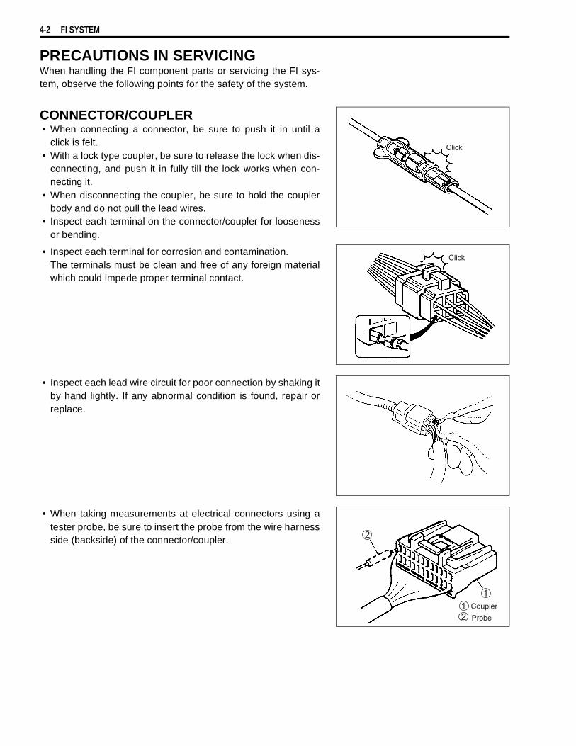
4-2 FI SYSTEM
PRECAUTIONS IN SERVICINGWhen handling the FI component parts or servicing the FI sys-tem, observe the following points for the safety of the system.
CONNECTOR/COUPLER• When connecting a connector, be sure to push it in until a
click is felt.• With a lock type coupler, be sure to release the lock when dis-
connecting, and push it in fully till the lock works when con-necting it.
• When disconnecting the coupler, be sure to hold the couplerbody and do not pull the lead wires.
• Inspect each terminal on the connector/coupler for loosenessor bending.
• Inspect each terminal for corrosion and contamination.The terminals must be clean and free of any foreign materialwhich could impede proper terminal contact.
• Inspect each lead wire circuit for poor connection by shaking itby hand lightly. If any abnormal condition is found, repair orreplace.
• When taking measurements at electrical connectors using atester probe, be sure to insert the probe from the wire harnessside (backside) of the connector/coupler.
Click
Click
Coupler
Probe
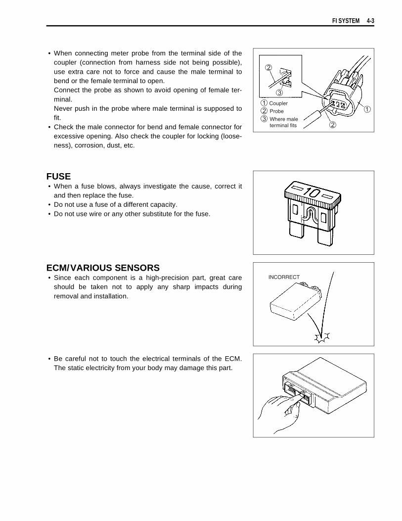
FI SYSTEM 4-3
• When connecting meter probe from the terminal side of thecoupler (connection from harness side not being possible),use extra care not to force and cause the male terminal tobend or the female terminal to open.Connect the probe as shown to avoid opening of female ter-minal.Never push in the probe where male terminal is supposed tofit.
• Check the male connector for bend and female connector forexcessive opening. Also check the coupler for locking (loose-ness), corrosion, dust, etc.
FUSE• When a fuse blows, always investigate the cause, correct it
and then replace the fuse.• Do not use a fuse of a different capacity.• Do not use wire or any other substitute for the fuse.
ECM/VARIOUS SENSORS• Since each component is a high-precision part, great care
should be taken not to apply any sharp impacts duringremoval and installation.
• Be careful not to touch the electrical terminals of the ECM.The static electricity from your body may damage this part.
Coupler
Probe
Where maleterminal fits
INCORRECT
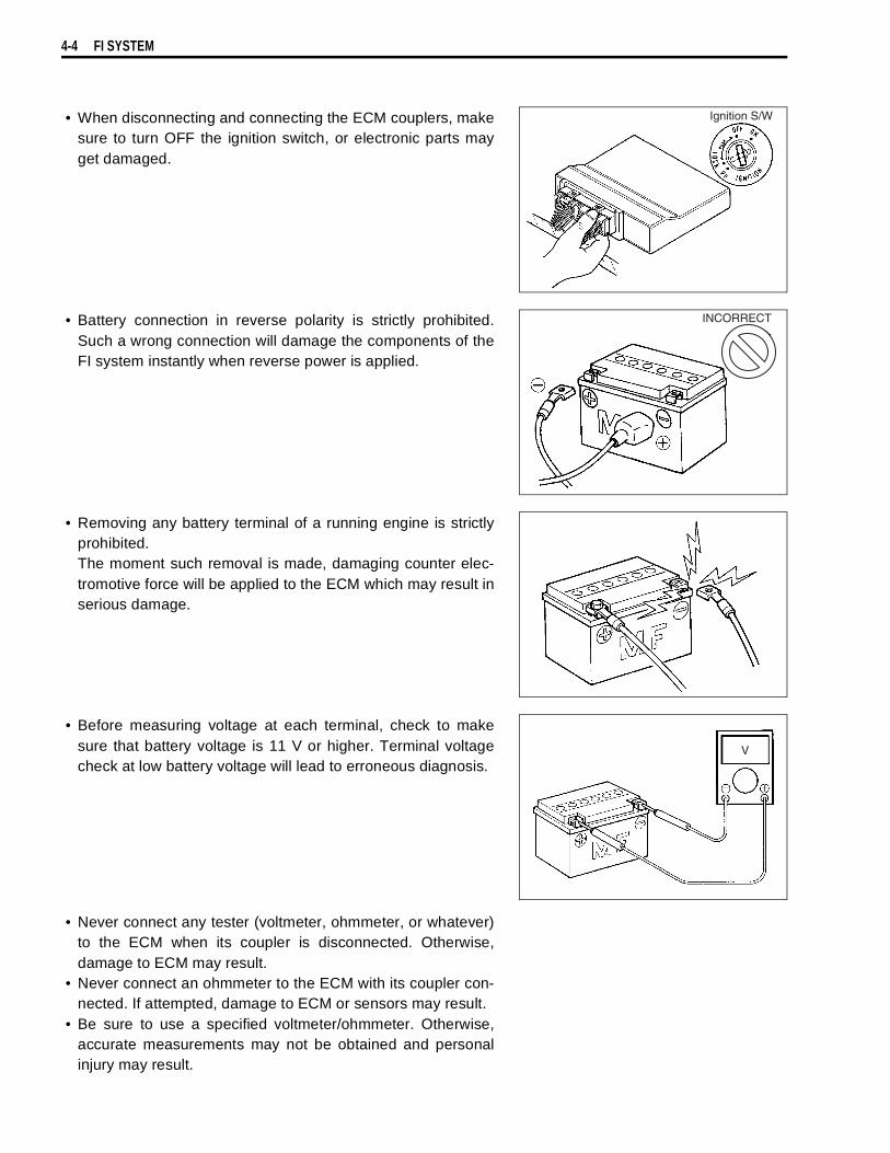
4-4 FI SYSTEM
• When disconnecting and connecting the ECM couplers, makesure to turn OFF the ignition switch, or electronic parts mayget damaged.
• Battery connection in reverse polarity is strictly prohibited.Such a wrong connection will damage the components of theFI system instantly when reverse power is applied.
• Removing any battery terminal of a running engine is strictlyprohibited.The moment such removal is made, damaging counter elec-tromotive force will be applied to the ECM which may result inserious damage.
• Before measuring voltage at each terminal, check to makesure that battery voltage is 11 V or higher. Terminal voltagecheck at low battery voltage will lead to erroneous diagnosis.
• Never connect any tester (voltmeter, ohmmeter, or whatever)to the ECM when its coupler is disconnected. Otherwise,damage to ECM may result.
• Never connect an ohmmeter to the ECM with its coupler con-nected. If attempted, damage to ECM or sensors may result.
• Be sure to use a specified voltmeter/ohmmeter. Otherwise,accurate measurements may not be obtained and personalinjury may result.
Ignition S/W
INCORRECT

FI SYSTEM 4-5
ELECTRICAL CIRCUIT INSPECTION PROCEDUREWhile there are various methods for electrical circuit inspection,described here is a general method to check for open and shortcircuit using an ohmmeter and a voltmeter.
OPEN CIRCUIT CHECKPossible causes for the open circuit are as follows. As the causecan exist in the connector/coupler or terminal, they need to bechecked carefully.• Loose connection of connector/coupler• Poor contact of terminal (due to dirt, corrosion or rust, poor
contact tension, entry of foreign object etc.)• Wire harness being open• Poor terminal-to-wire connection
• Disconnect the negative cable from the battery.• Check each connector/coupler at both ends of the circuit
being checked for loose connection. Also check for conditionof the coupler lock if equipped.
• Using a test male terminal, check the female terminals of thecircuit being checked for contact tension.Check each terminal visually for poor contact (possiblycaused by dirt, corrosion, rust, entry of foreign object, etc.). Atthe same time, check to make sure that each terminal is fullyinserted in the coupler and locked.If contact tension is not enough, rectify the contact to increasetension or replace.The terminals must be clean and free of any foreign materialwhich could impede proper terminal contact.
• Using continuity inspect or voltage check procedure asdescribed below, inspect the wire harness terminals for opencircuit and poor connection. Locate abnormality, if any.
Sensor
Check for loose connection
ECM
Check contact tension by inserting and removing.
Check each terminalfor bend and properalignment.
Looseness of crimping
Open
Thin wire (a few strands left)
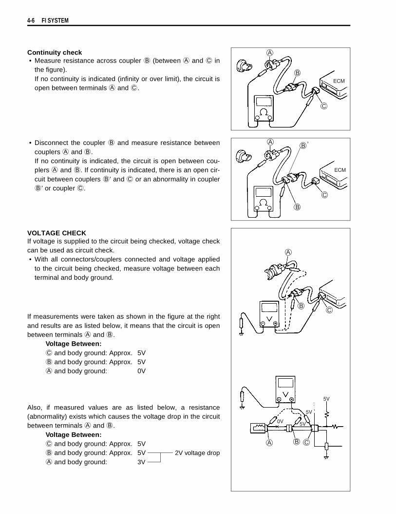
4-6 FI SYSTEM
Continuity check• Measure resistance across coupler
(between
and
inthe figure).If no continuity is indicated (infinity or over limit), the circuit isopen between terminals
and
.
• Disconnect the coupler
and measure resistance betweencouplers
and
.If no continuity is indicated, the circuit is open between cou-plers
and
. If continuity is indicated, there is an open cir-cuit between couplers
’ and
or an abnormality in coupler
’ or coupler
.
VOLTAGE CHECKIf voltage is supplied to the circuit being checked, voltage checkcan be used as circuit check.• With all connectors/couplers connected and voltage applied
to the circuit being checked, measure voltage between eachterminal and body ground.
If measurements were taken as shown in the figure at the rightand results are as listed below, it means that the circuit is openbetween terminals
and
.Voltage Between:
and body ground: Approx. 5V
and body ground: Approx. 5V
and body ground: 0V
Also, if measured values are as listed below, a resistance(abnormality) exists which causes the voltage drop in the circuitbetween terminals
and
.Voltage Between:
and body ground: Approx. 5V
and body ground: Approx. 5V 2V voltage drop
and body ground: 3V
ECM
ECM
’
0V 5V
5V
5V
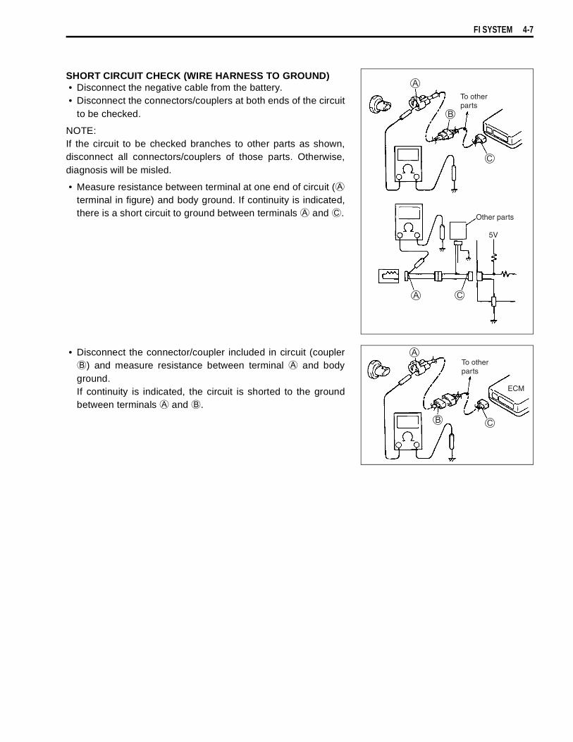
FI SYSTEM 4-7
SHORT CIRCUIT CHECK (WIRE HARNESS TO GROUND)• Disconnect the negative cable from the battery.• Disconnect the connectors/couplers at both ends of the circuit
to be checked.
NOTE:If the circuit to be checked branches to other parts as shown,disconnect all connectors/couplers of those parts. Otherwise,diagnosis will be misled.
• Measure resistance between terminal at one end of circuit (
terminal in figure) and body ground. If continuity is indicated,there is a short circuit to ground between terminals
and
.
• Disconnect the connector/coupler included in circuit (coupler
) and measure resistance between terminal
and bodyground.If continuity is indicated, the circuit is shorted to the groundbetween terminals
and
.
To otherparts
Other parts
5V
To otherparts
ECM

4-8 FI SYSTEM
USING TESTERS• Use the Suzuki multi-circuit tester (09900-25008).• Use well-charged batteries in the tester.• Be sure to set the tester to the correct testing range.
Using the tester• Incorrectly connecting the
and
probes may cause theinside of the tester to burnout.
• If the voltage and current are not known, make measure-ments using the highest range.
• When measuring the resistance with the multi-circuit tester, ∞will be shown as 10.00 MΩ and “1” flashes in the display.
• Check that no voltage is applied before making the measure-ment. If voltage is applied, the tester may be damaged.
• After using the tester, turn the power off.
09900-25008: Multi-circuit tester
NOTE:* When connecting the multi-circuit tester, use a fine needle
pointed probe or install fine copper wires (O.D is below0.5 mm) to the back side of the lead wire coupler and connectthe probes of tester to them.
* Use a fine copper wire, the outer diameter being below0.5 mm, to prevent the rubber of the water proof coupler fromdamage.
MULTI-CIRCUIT TESTER
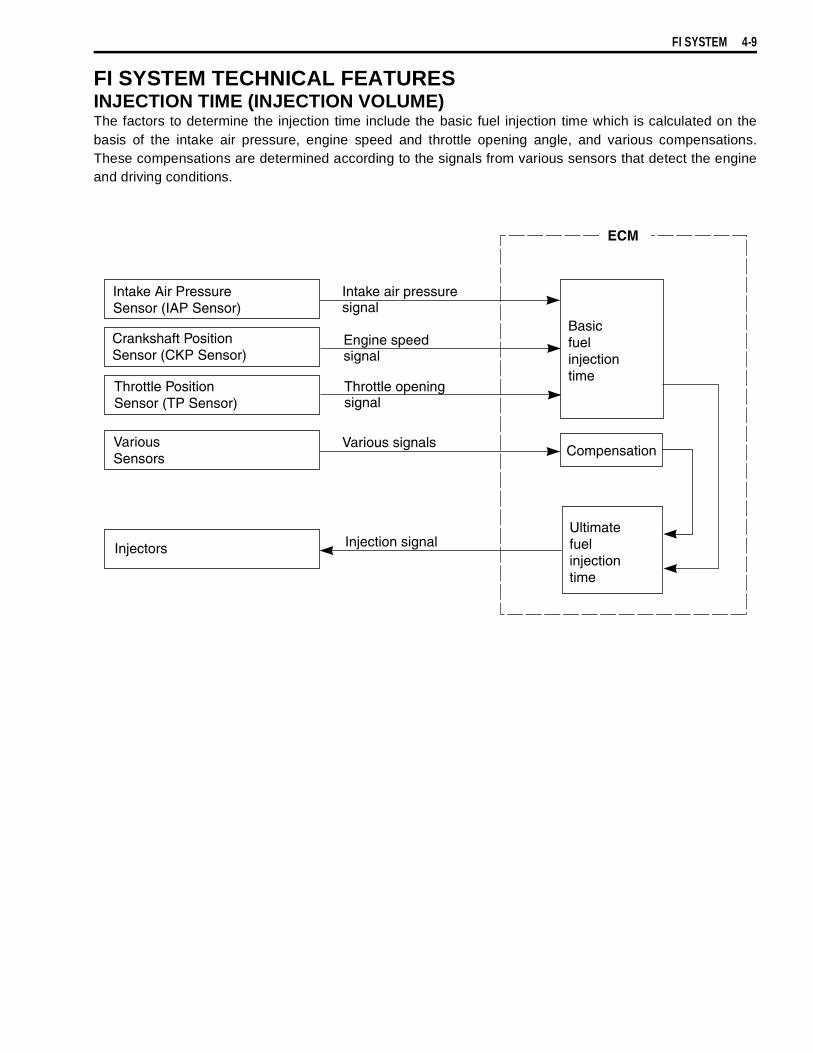
FI SYSTEM 4-9
FI SYSTEM TECHNICAL FEATURESINJECTION TIME (INJECTION VOLUME)The factors to determine the injection time include the basic fuel injection time which is calculated on thebasis of the intake air pressure, engine speed and throttle opening angle, and various compensations.These compensations are determined according to the signals from various sensors that detect the engineand driving conditions.
Intake Air PressureSensor (IAP Sensor)
Crankshaft PositionSensor (CKP Sensor)
Throttle PositionSensor (TP Sensor)
VariousSensors
Injectors
Intake air pressuresignal
Engine speedsignal
Various signals
Injection signal
Basicfuelinjectiontime
Compensation
Ultimatefuelinjectiontime
Throttle openingsignal
ECM
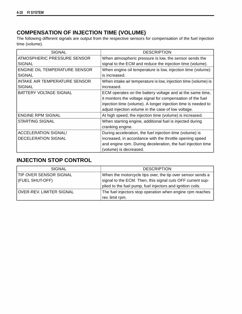
4-10 FI SYSTEM
COMPENSATION OF INJECTION TIME (VOLUME)The following different signals are output from the respective sensors for compensation of the fuel injectiontime (volume).
INJECTION STOP CONTROL
SIGNAL DESCRIPTION
ATMOSPHERIC PRESSURE SENSOR SIGNAL
When atmospheric pressure is low, the sensor sends the signal to the ECM and reduce the injection time (volume).
ENGINE OIL TEMPERATURE SENSOR SIGNAL
When engine oil temperature is low, injection time (volume) is increased.
INTAKE AIR TEMPERATURE SENSOR SIGNAL
When intake air temperature is low, injection time (volume) is increased.
BATTERY VOLTAGE SIGNAL ECM operates on the battery voltage and at the same time, it monitors the voltage signal for compensation of the fuel injection time (volume). A longer injection time is needed to adjust injection volume in the case of low voltage.
ENGINE RPM SIGNAL At high speed, the injection time (volume) is increased. STARTING SIGNAL When starting engine, additional fuel is injected during
cranking engine.ACCELERATION SIGNAL/DECELERATION SIGNAL
During acceleration, the fuel injection time (volume) is increased, in accordance with the throttle opening speed and engine rpm. During deceleration, the fuel injection time (volume) is decreased.
SIGNAL DESCRIPTION
TIP OVER SENSOR SIGNAL (FUEL SHUT-OFF)
When the motorcycle tips over, the tip over sensor sends a signal to the ECM. Then, this signal cuts OFF current sup-plied to the fuel pump, fuel injectors and ignition coils.
OVER-REV. LIMITER SIGNAL The fuel injectors stop operation when engine rpm reaches rev. limit rpm.
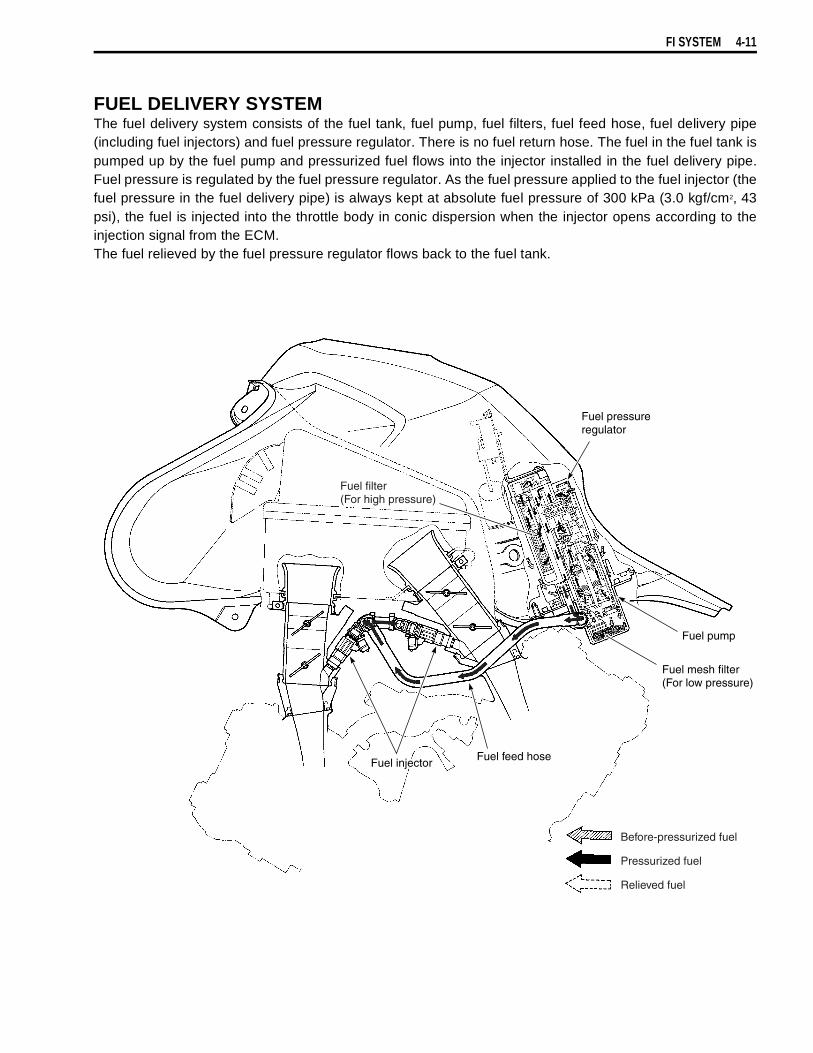
FI SYSTEM 4-11
FUEL DELIVERY SYSTEMThe fuel delivery system consists of the fuel tank, fuel pump, fuel filters, fuel feed hose, fuel delivery pipe(including fuel injectors) and fuel pressure regulator. There is no fuel return hose. The fuel in the fuel tank ispumped up by the fuel pump and pressurized fuel flows into the injector installed in the fuel delivery pipe.Fuel pressure is regulated by the fuel pressure regulator. As the fuel pressure applied to the fuel injector (thefuel pressure in the fuel delivery pipe) is always kept at absolute fuel pressure of 300 kPa (3.0 kgf/cm2, 43psi), the fuel is injected into the throttle body in conic dispersion when the injector opens according to theinjection signal from the ECM.The fuel relieved by the fuel pressure regulator flows back to the fuel tank.
Fuel pressureregulator
Fuel pump
Fuel mesh filter(For low pressure)
Fuel feed hoseFuel injector
Fuel filter(For high pressure)
Before-pressurized fuel
Pressurized fuel
Relieved fuel

4-12 FI SYSTEM
FUEL PUMPThe electric fuel pump is mounted at the bottom of the fuel tank, which consists of the armature, magnet,impeller, brush, check valve and relief valve. The ECM controls its ON/OFF operation as controlled underthe FUEL PUMP CONTROL SYSTEM.When electrical energy is supplied to the fuel pump, the motor in the pump runs and together with the impel-ler. This causes a pressure difference to occur on both sides of the impeller as there are many groovesaround it. Then the fuel is drawn through the inlet port, and with its pressure increased, it is dischargedthrough the outlet port. The fuel pump has a check valve to keep some pressure in the fuel feed hose evenwhen the fuel pump is stopped. Also, the relief valve is equipped in the fuel pump, which releases pressur-ized fuel to the fuel tank when the outlet of the fuel pressure has increased up to 450 – 600 kPa (4.5 – 6.0kgf/cm2, 64 – 85 psi).
When the impeller is driven by the motor, pressure differential occurs between the front part and the rearpart of the blade groove as viewed in angular direction due to fluid friction. This process continuously takesplace causing fuel pressure to be built up. The pressurized fuel is then let out from the pump chamber anddischarged through the motor section and the check valve.
Relief valveBrush
Outlet port
Check valve Armature
Magnet Impeller
Inlet port
OutletBlade groove
Inlet
Flow clearance
Turning direction
Motor shaft
Vortex flow
Impeller

FI SYSTEM 4-13
FUEL PRESSURE REGULATORThe fuel pressure regulator consists of the spring and valve. It keeps absolute fuel pressure of 300 kPa(3.0 kgf/cm2, 43 psi) to be applied to the injector at all times. When the fuel pressure rises more than 300 kPa (3.0 kgf/cm2, 43 psi), the fuel pushes the valve in the regu-lator open and excess fuel returns to the fuel tank.
FUEL INJECTORThe fuel injector consists of the solenoid coil, plunger, needle valve and filter.It is an electromagnetic type injection nozzle which injects fuel in the throttle body according to the signalfrom the ECM.When the solenoid coil of the injector is energized by the ECM, it becomes an electromagnet and attractsthe plunger. At the same time, the needle valve incorporated with the plunger opens and the injector whichis under the fuel pressure injects fuel in conic dispersion. As the lift stroke of the needle valve of the injectoris set constant, the volume of the fuel injected at one time is determined by the length of time during whichthe solenoid coil is energized (injection time).
Fuel fromfuel pump
Spring
Valve
Fuel fromfuel pump
Spring
Valve
Fuel returns to thefuel tank
Filter
Solenoid coilPlunger
Needle valve

4-14 FI SYSTEM
FUEL PUMP CONTROL SYSTEMWhen the ignition switch is turned on, current from the battery flows to the fuel pump motor through the side-stand relay and the fuel pump relay causing the motor to turn.Since the ECM has a timer function, the fuel pump motor stops turning in three seconds after the switch hasbeen turned on.Thereafter, when the crankshaft is turned by the starter motor or the engine has been started, the enginerevolving signal is input to the ECM. Then, current flows to the fuel pump motor from the battery through theside-stand relay and the fuel pump relay so that the pump continues to function. A tip over sensor is provided in the fuel pump control circuit. By this provision, anytime the motorcycle tipsover, the tip over sensor sends a signal to the ECM to turn off power to the fuel pump relay, causing the fuelpump motor to stop. At the same time, current to the fuel injectors as well as the ignition coil is interrupted,which then stops the engine.
BATTERY TIP OVERSENSOR
30 A
IG SWITCH
15 A
15 A
FUEL PUMP RELAY
SIDE-STAND RELAY
ENGINESTOPSWITCH
STARTERBUTTON
FUELPUMP
EC
M
IG2 IG1
SPARKPLUG
SPARKPLUG
CMPS
CKPS
CLPS
SIDE-STANDSWITCH
STARTERRELAY
STARTERMOTOR

FI SYSTEM 4-15
ECM (FI CONTROL UNIT)The ECM is located under the seat.The ECM consists of CPU (Central Processing Unit), memory (ROM) and I/O (Input/Output) sections. Thesignal from each sensor is sent to the input section and then sent to CPU. On the basis of signal informationreceived, CPU calculates the volume of fuel necessary for injection using maps programmed for varyingengine conditions. Then, the operation signal of the fuel injection is sent from the output section to the fuelinjector.The eight kinds of independent program maps are programmed in the ROM. These eight kinds of maps are designed to compensate for differences of the intake/exhaust systems andcooling performance.LIGHT LOAD: When the engine is running in a light load, the fuel injected volume (time) is determined the
on basis of the intake air pressure and engine speed.HEAVY LOAD:When the engine is running in a heavy load, the fuel injected volume (time) is determined on
the basis of the throttle valve opening and engine speed.
INJECTION TIMINGThe system employs a sequential, front-and-rear-cylinder independent injection type, using the crankshaftposition sensor (signal generator) to determine the piston position (injection timing and ignition timing) andthe camshaft position sensor to identify the cylinder during operation, and these information are sent to theECM. This makes it possible to inject the optimum volume of fuel in the best timing for the engine operatingconditions.
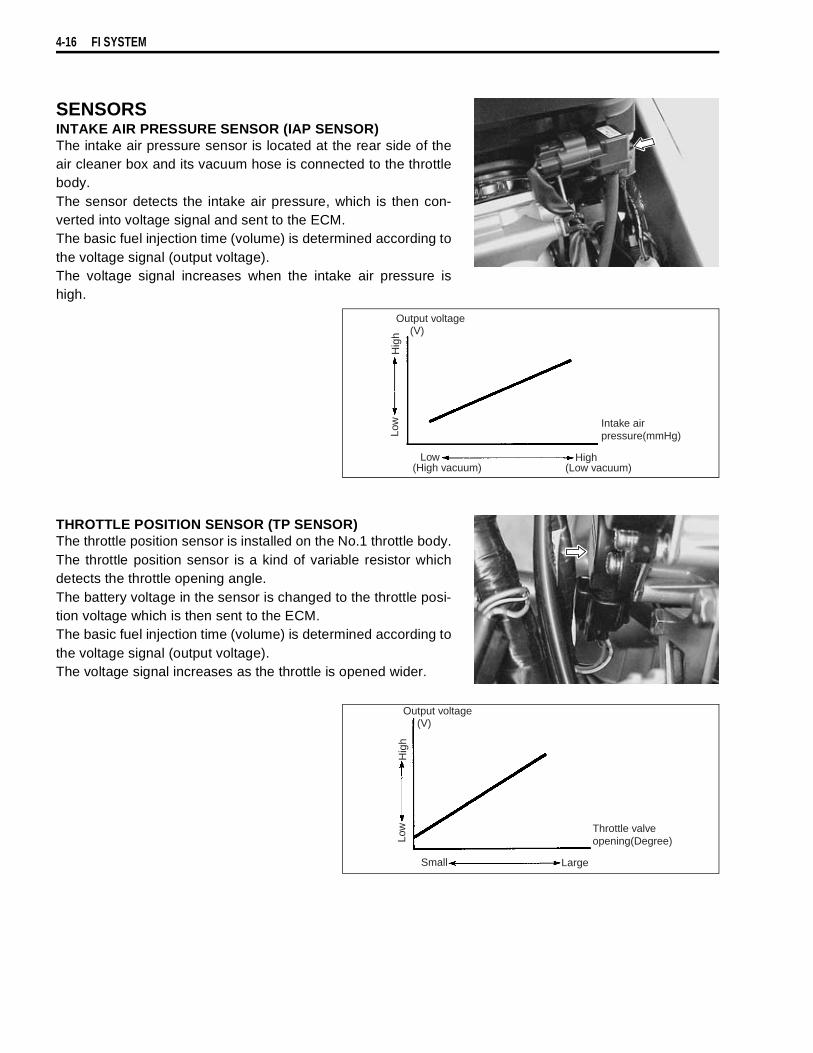
4-16 FI SYSTEM
SENSORSINTAKE AIR PRESSURE SENSOR (IAP SENSOR)The intake air pressure sensor is located at the rear side of theair cleaner box and its vacuum hose is connected to the throttlebody.The sensor detects the intake air pressure, which is then con-verted into voltage signal and sent to the ECM.The basic fuel injection time (volume) is determined according tothe voltage signal (output voltage).The voltage signal increases when the intake air pressure ishigh.
THROTTLE POSITION SENSOR (TP SENSOR)The throttle position sensor is installed on the No.1 throttle body.The throttle position sensor is a kind of variable resistor whichdetects the throttle opening angle.The battery voltage in the sensor is changed to the throttle posi-tion voltage which is then sent to the ECM.The basic fuel injection time (volume) is determined according tothe voltage signal (output voltage).The voltage signal increases as the throttle is opened wider.
Output voltage(V)
Low
Hig
h
Low High(High vacuum) (Low vacuum)
Intake airpressure(mmHg)
Output voltage(V)
Low
Hig
h
Small Large
Throttle valveopening(Degree)
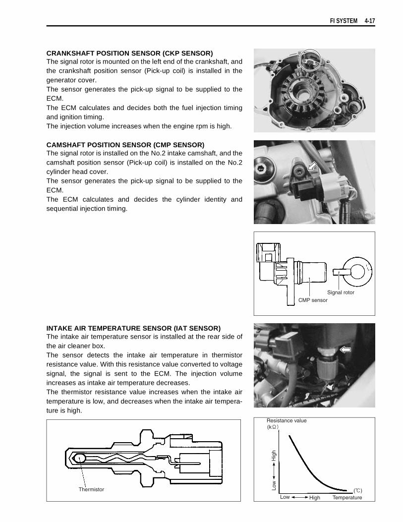
FI SYSTEM 4-17
CRANKSHAFT POSITION SENSOR (CKP SENSOR)The signal rotor is mounted on the left end of the crankshaft, andthe crankshaft position sensor (Pick-up coil) is installed in thegenerator cover.The sensor generates the pick-up signal to be supplied to theECM.The ECM calculates and decides both the fuel injection timingand ignition timing.The injection volume increases when the engine rpm is high.
CAMSHAFT POSITION SENSOR (CMP SENSOR)The signal rotor is installed on the No.2 intake camshaft, and thecamshaft position sensor (Pick-up coil) is installed on the No.2cylinder head cover.The sensor generates the pick-up signal to be supplied to theECM.The ECM calculates and decides the cylinder identity andsequential injection timing.
INTAKE AIR TEMPERATURE SENSOR (IAT SENSOR)The intake air temperature sensor is installed at the rear side ofthe air cleaner box.The sensor detects the intake air temperature in thermistorresistance value. With this resistance value converted to voltagesignal, the signal is sent to the ECM. The injection volumeincreases as intake air temperature decreases.The thermistor resistance value increases when the intake airtemperature is low, and decreases when the intake air tempera-ture is high.
Resistance value
Low
Hig
h
Low High Temperature
Thermistor
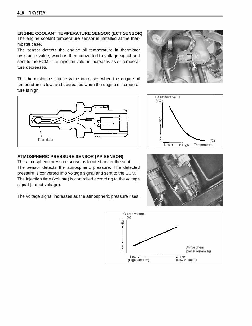
4-18 FI SYSTEM
ENGINE COOLANT TEMPERATURE SENSOR (ECT SENSOR)The engine coolant temperature sensor is installed at the ther-mostat case.The sensor detects the engine oil temperature in thermistorresistance value, which is then converted to voltage signal andsent to the ECM. The injection volume increases as oil tempera-ture decreases.
The thermistor resistance value increases when the engine oiltemperature is low, and decreases when the engine oil tempera-ture is high.
ATMOSPHERIC PRESSURE SENSOR (AP SENSOR)The atmospheric pressure sensor is located under the seat.The sensor detects the atmospheric pressure. The detectedpressure is converted into voltage signal and sent to the ECM.The injection time (volume) is controlled according to the voltagesignal (output voltage).
The voltage signal increases as the atmospheric pressure rises.
Resistance value
Low
Hig
h
TemperatureLow High
Thermistor
Output voltage(V)
Low
Hig
h
Low High(High vacuum) (Low vacuum)
Atmosphericpressure(mmHg)
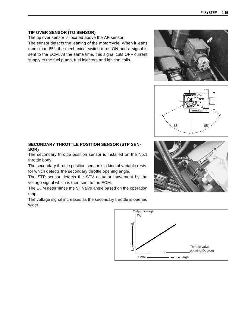
FI SYSTEM 4-19
TIP OVER SENSOR (TO SENSOR)The tip over sensor is located above the AP sensor.The sensor detects the leaning of the motorcycle. When it leansmore than 65°, the mechanical switch turns ON and a signal issent to the ECM. At the same time, this signal cuts OFF currentsupply to the fuel pump, fuel injectors and ignition coils.
SECONDARY THROTTLE POSITION SENSOR (STP SEN-SOR)The secondary throttle position sensor is installed on the No.1throttle body.The secondary throttle position sensor is a kind of variable resis-tor which detects the secondary throttle opening angle.The STP sensor detects the STV actuator movement by thevoltage signal which is then sent to the ECM.The ECM determines the ST valve angle based on the operationmap.The voltage signal increases as the secondary throttle is openedwider.
65˚65˚
Output voltage(V)
Low
Hig
h
Small Large
Throttle valveopening(Degree)
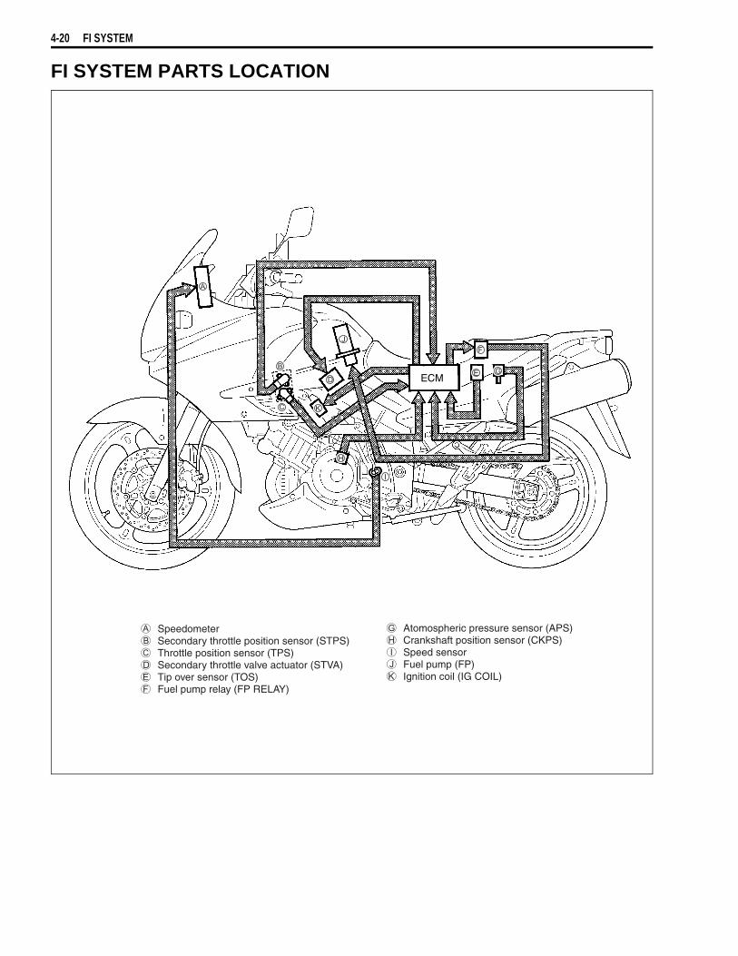
4-20 FI SYSTEM
FI SYSTEM PARTS LOCATION
ECM
Speedometer Secondary throttle position sensor (STPS) Throttle position sensor (TPS) Secondary throttle valve actuator (STVA) Tip over sensor (TOS) Fuel pump relay (FP RELAY)
Atomospheric pressure sensor (APS) Crankshaft position sensor (CKPS) Speed sensor Fuel pump (FP) Ignition coil (IG COIL)

FI SYSTEM 4-21
ECM
Intake air temperature sensor (IATS) Intake air pressure sensor (IAPS) Camshaft position sensor (CMPS) Engine coolant temperature sensor (ECTS)
Gear position switch Heated oxygen sensor (HO2S) PAIR solenoid valve Fuel injector (FI)
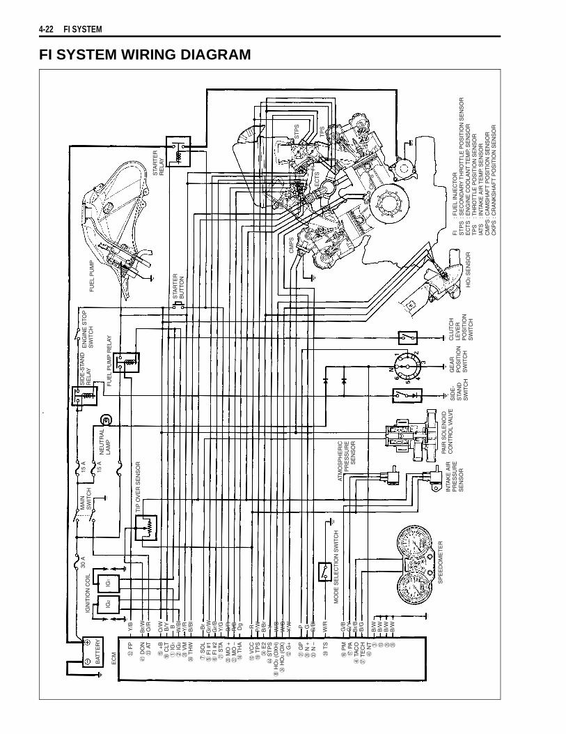
4-22 FI SYSTEM
FI SYSTEM WIRING DIAGRAM
BAT
TE
RY
EC
M
IGN
ITIO
N C
OIL
30 A
15 A
15 A
IG2
IG1
MA
INS
WIT
CH
NE
UT
RA
LLA
MP
SID
E-S
TAN
DR
ELA
YE
NG
INE
STO
PS
WIT
CH
FU
EL
PU
MP
RE
LAY
FU
EL
PU
MP
STA
RT
ER
BU
TTO
N
STA
RT
ER
RE
LAY
CM
PS
IAT
S
ST
PS
EC
TS
CK
PS
TP
S
TIP
OV
ER
SE
NS
OR
FI
IAT
S
CK
PS
FI
FI
: FU
EL
INJE
CTO
RS
TP
S: S
EC
ON
DA
RY
TH
RO
TT
LE P
OS
ITIO
N S
EN
SO
RE
CT
S: E
NG
INE
CO
OLA
NT
TE
MP.
SE
NS
OR
TP
S: T
HR
OT
TLE
PO
SIT
ION
SE
NS
OR
IAT
S: I
NTA
KE
AIR
TE
MP.
SE
NS
OR
CM
PS
: CA
MS
HA
FT
PO
SIT
ION
SE
NS
OR
CK
PS
: CR
AN
KS
HA
FT
PO
SIT
ION
SE
NS
OR
HO
2 S
EN
SO
R
CLU
TC
HLE
VE
RP
OS
ITIO
NS
WIT
CH
GE
AR
PO
SIT
ION
SW
ITC
H
SID
E-
STA
ND
SW
ITC
H
PAIR
SO
LEN
OID
CO
NT
RO
L V
ALV
EIN
TAK
E A
IRP
RE
SS
UR
ES
EN
SO
R
SP
EE
DO
ME
TE
R
ATM
OS
PH
ER
ICP
RE
SS
UR
ES
EN
SO
R
MO
DE
SE
LEC
TIO
N S
WIT
CH
Y/B
Br/
WO
/R
O/W
B/Y B
W/B
lY
/RB
/Bl
Br
Gr/
WG
r/B
Y/G
B/R
R/B Dg R
P/W
B/B
rY
W/B
W/G
Y/W P G
G/B
l
W/R
G/B
G/Y
Br/
BB
/G
B/W
B/W
B/W
B/WY/B
Br/
WO
/R
O/W
B/Y B
W/B
lY
/RB
/Bl
Br
Gr/
WG
r/B
Y/G
B/R
R/B Dg R
P/W
B/B
rY
W/B
W/G
Y/W P G
G/B
l
W/R
G/B
G/Y
Br/
BB
/G
B/W
B/W
B/W
B/W
F
P
D
ON
A
T
+
B
CLT
IG
1
IG
2
V
M
TH
W
S
OL
F
I #1
F
I #2
S
TA
MO
+
MO
–
TH
A
V
CC
T
PS
E
2
ST
PS
H
O2
(OX
H)
H
O2
(OX
)
G+
G
P
N +
N
–
T
S
P
M
PA
T
AC
O
TE
CH
N
T ! " #

FI SYSTEM 4-23
SELF-DIAGNOSIS FUNCTIONThe self-diagnosis function is incorporated in the ECM. The function has two modes, “User mode” and“Dealer mode”. The user can only be notified by the LCD (DISPLAY) panel and LED (FI light). To check thefunction of the individual FI system devices, the dealer mode is prepared. In this check, the special tool isnecessary to read the code of the malfunction items.
USER MODE
*1When one of the signals is not received by ECM, the fail-safe circuit works and injection is not stopped. Inthis case, “FI” and odometer are indicated in the LCD panel and motorcycle can run.*2The injection signal is stopped, when the crankshaft position sensor signal, tip over sensor signal, #1/#2ignition signals, #1/#2 injector signals, fuel pump relay signal or ignition switch signal is not sent to ECM. Inthis case, “FI” is indicated in the LCD panel. Motorcycle does not run.“CHEC”: The LCD panel indicates “CHEC” when no communication signal from the ECM is received for
3 seconds.For Example:The ignition switch is turned ON, and the engine stop switch is turned OFF. In this case, the speed-ometer does not receive any signal from the ECM, and the panel indicates “CHEC”.If CHEC is indicated, the LCD does not indicate the trouble code. It is necessary to check the wir-ing harness between ECM and speedometer couplers.The possible cause of this indication is as follows;Engine stop switch is in OFF position. Side-stand/ignition inter-lock system is not working. Ignitionfuse is burnt.
MALFUNCTIONLCD (DISPLAY)
INDICATIONFI LIGHT
INDICATIONINDICATION MODE
“NO” Odometer ––– –––“YES”
Engine can start
Odometer and“FI” letters*1
FI light turns ON. Each 2 sec. Odometeror “FI” is indicated.
Engine can not start “FI” letters*2
FI light turns ONand blinks.
“FI” is indicatedcontinuously.

4-24 FI SYSTEM
DEALER MODEThe defective function is memorized in the computer. Use the special tool’s coupler to connect to the dealermode coupler. The memorized malfunction code is displayed on LCD (DISPLAY) panel. Malfunction meansthat the ECM does not receive signal from the devices. These affected devices are indicated in the codeform.
09930-82710: Mode select switch
Before checking the malfunction code, do not disconnect the ECM lead wire couplers.If the couplers from the ECM are disconnected, the malfunction code memory is erased and themalfunction code can not checked.
MALFUNCTIONLCD (DISPLAY)
INDICATIONFI LIGHT INDICATION INDICATION MODE
“NO” C00
FI light turns OFF.
–––
“YES”C** code is indicatedfrom small numeral tolarge one.
For each 2 sec., code isindicated.

FI SYSTEM 4-25
In the LCD (DISPLAY) panel, the malfunction code is indicated from small code to large code.*3When the secondary throttle valve actuator and secondary throttle position sensor signals are not sent toECM, C29 is indicated.
TPS ADJUSTMENT1. Adjust the engine rpm to 1 200 ± 100 rpm. ( 2-14)2. Stop the engine and connect the special tool (Mode select
switch) to the dealer mode coupler at the wiring harness.3. If the throttle position sensor adjustment is necessary, loosen
the screws and turn the throttle position sensor and bring theline to middle.
4. Then, tighten the screws to fix the throttle position sensor.
09930-11950: Torx wrench
The LCD indicates 0.4 sec./time.The correct position must be determined when the middle line isindicated twice or more, where the sensor should be fixed.
CODE MALFUNCTION PART REMARKS
C00C11C12C13C14C15C21C22C23C24C25C28C29C31C32C33C41C42C44
NoneCamshaft position sensor (CMPS)Crankshaft position sensor (CKPS)Intake air pressure sensor (IAPS)Throttle position sensor (TPS)Engine coolant temp. sensor (ECTS)Intake air temp. sensor (IATS)Atmospheric pressure sensor (APS)Tip over sensor (TOS)Ignition signal #1 (IG coil #1)Ignition signal #2 (IG coil #2)Secondary throttle valve actuator (STVA)Secondary throttle position sensor (STPS)Gear position signal (GP switch)Injector signal #1 (FI #1)Injector signal #2 (F1 #2)Fuel pump control system (FP control system)Ignition switch signal (IG switch signal)Heated oxygen sensor (HO2S)
No defective part
Pick-up coil signal, signal generator
For #1 cylinderFor #2 cylinder*3
For #1 cylinderFor #2 cylinderFuel pump, Fuel pump relayAnti-theft
Incorrect
Position correcte
Incorrect
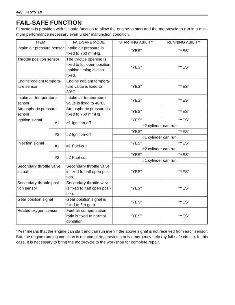
4-26 FI SYSTEM
FAIL-SAFE FUNCTIONFI system is provided with fail-safe function to allow the engine to start and the motorcycle to run in a mini-mum performance necessary even under malfunction condition.
“Yes” means that the engine can start and can run even if the above signal is not received from each sensor.But, the engine running condition is not complete, providing only emergency help (by fail-safe circuit). In thiscase, it is necessary to bring the motorcycle to the workshop for complete repair.
ITEM FAIL-SAFE MODE STARTING ABILITY RUNNING ABILITY
Intake air pressure sensor Intake air pressure is fixed to 760 mmHg.
“YES” “YES”
Throttle position sensor The throttle opening is fixed to full open position.Ignition timing is also fixed.
“YES” “YES”
Engine coolant tempera-ture sensor
Engine coolant tempera-ture value is fixed to 80°C.
“YES” “YES”
Intake air temperature sensor
Intake air temperature value is fixed to 40°C.
“YES” “YES”
Atmospheric pressure sensor
Atmospheric pressure is fixed to 760 mmHg.
“YES” “YES”
Ignition signal#1 #1 Ignition-off
“YES” “YES”#2 cylinder can run.
#2 #2 Ignition-off“YES” “YES”
#1 cylinder can run.
Injection signal#1 #1 Fuel-cut
“YES” “YES”#2 cylinder can run.
#2 #2 Fuel-cut“YES” “YES”
#1 cylinder can run.
Secondary throttle valve actuator
Secondary throttle valve is fixed to half open posi-tion.
“YES” “YES”
Secondary throttle posi-tion sensor
Secondary throttle valve is fixed to half open posi-tion.
“YES” “YES”
Gear position signal Gear position signal is fixed to 6th gear.
“YES” “YES”
Heated oxygen sensor Fuel-air compensation ratio is fixed to normal condition.
“YES” “YES”

FI SYSTEM 4-27
FI SYSTEM TROUBLESHOOTINGCUSTOMER COMPLAINT ANALYSISRecord details of the problem (failure, complaint) and how it occurred as described by the customer. For thispurpose, use of such an inspection form will facilitate collecting information to the point required for properanalysis and diagnosis.
EXAMPLE: CUSTOMER PROBLEM INSPECTION FORM
User name: Model: VIN:Date of issue: Date Reg. Date of problem: Mileage:
Malfunction indicator lamp condition (LED)
Always ON Sometimes ON Always OFF Good condition
Malfunction display/code (LCD)
User mode: No display Malfunction display ( )Dealer mode: No code Malfunction code ( )
PROBLEM SYMPTOMS
Difficult Starting Poor Driveability No cranking Hesitation on acceleration
No initial combustion Back fire/ After fire
No combustion Lack of powerPoor starting at( cold warm always)
Surging
Abnormal knockingOther Other
Poor Idling Engine Stall whenPoor fast Idle Immediately after start
Abnormal idling speed( High Low) ( r/min)
Throttle valve is openedThrottle valve is closed
Unstable Load is appliedHunting ( r/min. to r/min) Other
Other OTHERS:
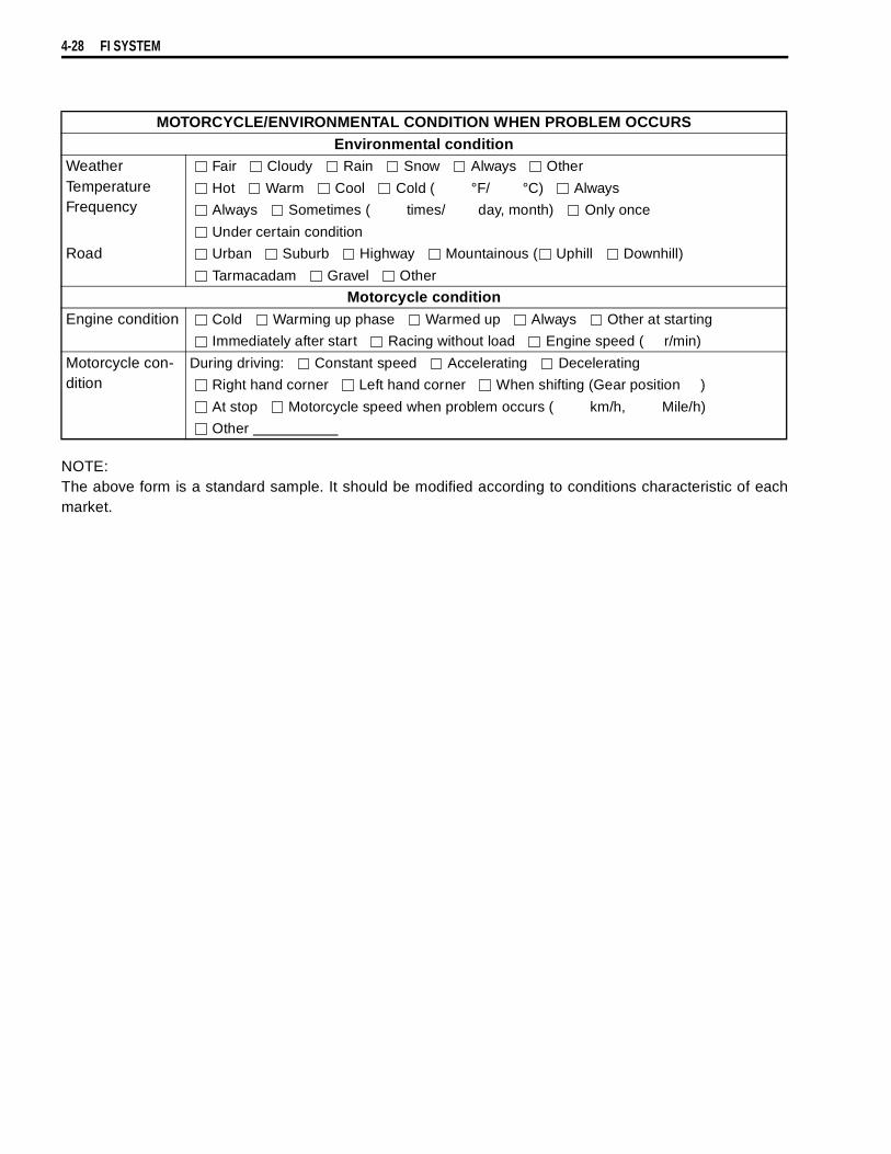
4-28 FI SYSTEM
NOTE:The above form is a standard sample. It should be modified according to conditions characteristic of eachmarket.
MOTORCYCLE/ENVIRONMENTAL CONDITION WHEN PROBLEM OCCURSEnvironmental condition
WeatherTemperatureFrequency
Fair Cloudy Rain Snow Always Other
Hot Warm Cool Cold ( °F/ °C) Always
Always Sometimes ( times/ day, month) Only once
Under certain condition
Road Urban Suburb Highway Mountainous ( Uphill Downhill)
Tarmacadam Gravel Other
Motorcycle conditionEngine condition Cold Warming up phase Warmed up Always Other at starting
Immediately after start Racing without load Engine speed ( r/min)
Motorcycle con-dition
During driving: Constant speed Accelerating Decelerating
Right hand corner Left hand corner When shifting (Gear position )
At stop Motorcycle speed when problem occurs ( km/h, Mile/h)
Other
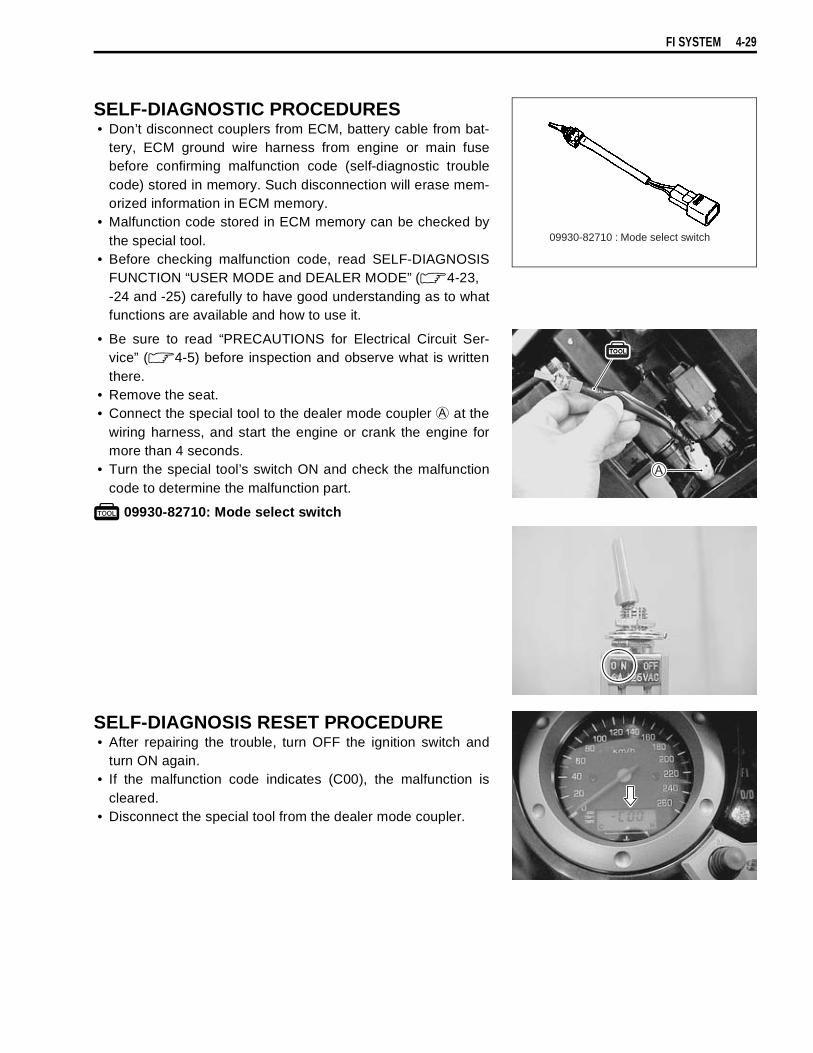
FI SYSTEM 4-29
SELF-DIAGNOSTIC PROCEDURES• Don’t disconnect couplers from ECM, battery cable from bat-
tery, ECM ground wire harness from engine or main fusebefore confirming malfunction code (self-diagnostic troublecode) stored in memory. Such disconnection will erase mem-orized information in ECM memory.
• Malfunction code stored in ECM memory can be checked bythe special tool.
• Before checking malfunction code, read SELF-DIAGNOSISFUNCTION “USER MODE and DEALER MODE” ( 4-23,-24 and -25) carefully to have good understanding as to whatfunctions are available and how to use it.
• Be sure to read “PRECAUTIONS for Electrical Circuit Ser-vice” ( 4-5) before inspection and observe what is writtenthere.
• Remove the seat.• Connect the special tool to the dealer mode coupler
at thewiring harness, and start the engine or crank the engine formore than 4 seconds.
• Turn the special tool’s switch ON and check the malfunctioncode to determine the malfunction part.
09930-82710: Mode select switch
SELF-DIAGNOSIS RESET PROCEDURE• After repairing the trouble, turn OFF the ignition switch and
turn ON again.• If the malfunction code indicates (C00), the malfunction is
cleared.• Disconnect the special tool from the dealer mode coupler.
09930-82710 : Mode select switch
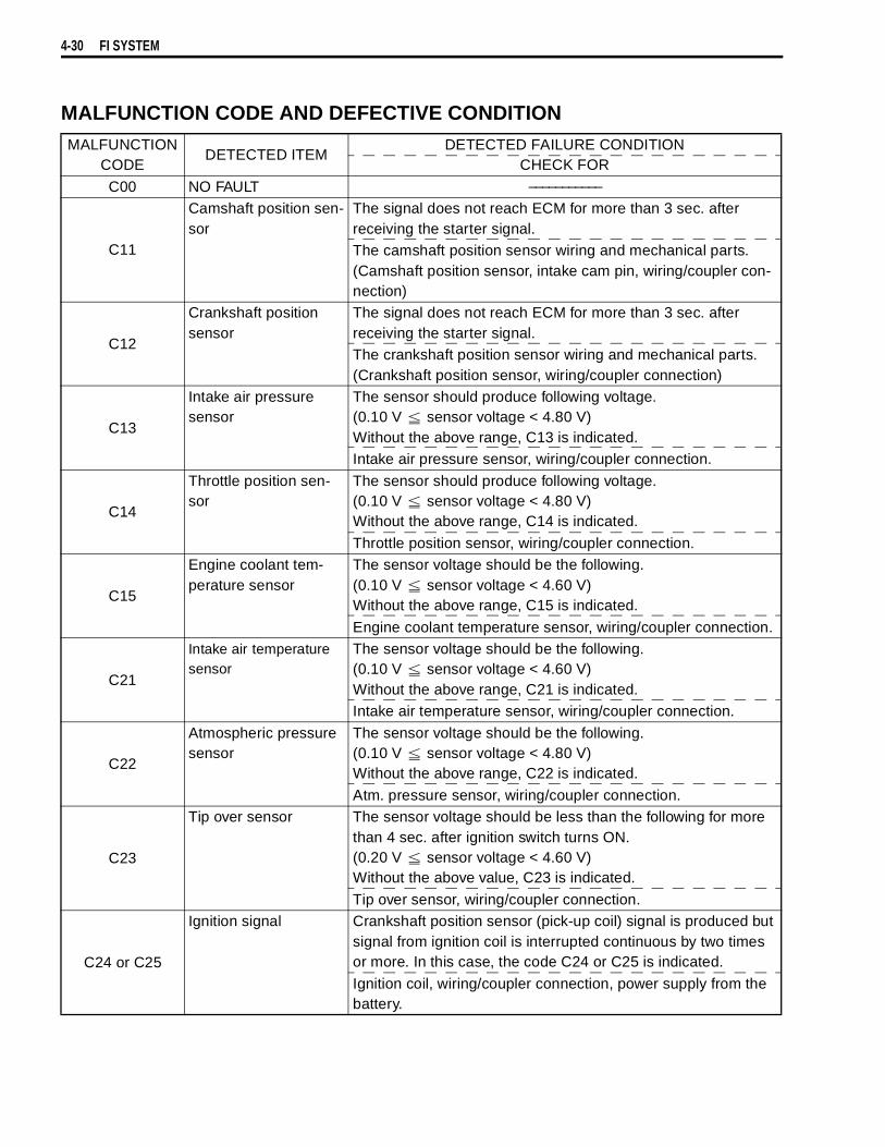
4-30 FI SYSTEM
MALFUNCTION CODE AND DEFECTIVE CONDITIONMALFUNCTION
CODEDETECTED ITEM
DETECTED FAILURE CONDITIONCHECK FOR
C00 NO FAULT –––––––––––
C11
Camshaft position sen-sor
The signal does not reach ECM for more than 3 sec. after receiving the starter signal.The camshaft position sensor wiring and mechanical parts. (Camshaft position sensor, intake cam pin, wiring/coupler con-nection)
C12
Crankshaft position sensor
The signal does not reach ECM for more than 3 sec. after receiving the starter signal.The crankshaft position sensor wiring and mechanical parts. (Crankshaft position sensor, wiring/coupler connection)
C13
Intake air pressure sensor
The sensor should produce following voltage.(0.10 V sensor voltage < 4.80 V)Without the above range, C13 is indicated.Intake air pressure sensor, wiring/coupler connection.
C14
Throttle position sen-sor
The sensor should produce following voltage.(0.10 V sensor voltage < 4.80 V)Without the above range, C14 is indicated.
Throttle position sensor, wiring/coupler connection.
C15
Engine coolant tem-perature sensor
The sensor voltage should be the following.(0.10 V sensor voltage < 4.60 V)Without the above range, C15 is indicated.
Engine coolant temperature sensor, wiring/coupler connection.
C21
Intake air temperature sensor
The sensor voltage should be the following.(0.10 V sensor voltage < 4.60 V)Without the above range, C21 is indicated.Intake air temperature sensor, wiring/coupler connection.
C22
Atmospheric pressure sensor
The sensor voltage should be the following.(0.10 V sensor voltage < 4.80 V)Without the above range, C22 is indicated.
Atm. pressure sensor, wiring/coupler connection.
C23
Tip over sensor The sensor voltage should be less than the following for more than 4 sec. after ignition switch turns ON.(0.20 V sensor voltage < 4.60 V)Without the above value, C23 is indicated.
Tip over sensor, wiring/coupler connection.
C24 or C25
Ignition signal Crankshaft position sensor (pick-up coil) signal is produced but signal from ignition coil is interrupted continuous by two times or more. In this case, the code C24 or C25 is indicated.
Ignition coil, wiring/coupler connection, power supply from the battery.

FI SYSTEM 4-31
C28
Secondary throttle valve actuator
When no actuator control signal is supplied from the ECM or communication signal does not reach ECM or operation voltage does not reach STVA motor, C28 is indicated. STVA can not operate.
STVA lead wire/coupler.
C29
Secondary throttle posi-tion sensor
The sensor should produce following voltage. (0.10 V sensor voltage < 4.80 V)Without the above range, C29 is indicated.
Secondary throttle position sensor, wiring/coupler connection.
C31
Gear position signal Gear position signal voltage should be higher than the following for more than 4 seconds.(Gear position switch voltage > 1.0 V)Without the above value, C31 is indicated.
Gear position sensor, wiring/coupler connection. Gearshift cam etc.
C32 or C33Fuel injector signal When fuel injection signal stops, the C32 or C33 is indicated.
Injector, wiring/coupler connection, power supply to the injector.
C41
Fuel pump relay signal When no signal is supplied from fuel pump relay, C41 is indi-cated.Fuel pump relay, connecting lead, power source to fuel pump relay.
C42Ignition switch signal Ignition switch signal is not input in the ECM.
Ignition switch, lead wire/coupler.
C44
Heated oxygen sensor(HO2S)
The sensor voltage should be less than the following after warming up condition.(Sensor voltage < 0.4 V)Without the above value, C44 is indicated.Heater operation voltage does not reach in the oxygen heater circuit, C44 in indicated.The Heater can not operate.
HO2S lead wire/coupler connection.Battery voltage supply to the HO2S.
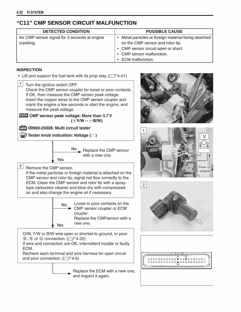
4-32 FI SYSTEM
“C11” CMP SENSOR CIRCUIT MALFUNCTION
INSPECTION
DETECTED CONDITION POSSIBLE CAUSENo CMP sensor signal for 3 seconds at engine cranking.
• Metal particles or foreign material being attached on the CMP sensor and rotor tip.
• CMP sensor circuit open or short.• CMP sensor malfunction.• ECM malfunction.
Remove the CMP sensor.If the metal particles or foreign material is attached on theCMP sensor and rotor tip, signal not flow correctly to theECM. Clean the CMP sensor and rotor tip with a spray-type carburetor cleaner and blow dry with compressedair and also change the engine oil if necessary.
• Lift and support the fuel tank with its prop stay. (4-51)
1 Turn the ignition switch OFF.Check the CMP sensor coupler for loose or poor contacts.If OK, then measure the CMP sensor peak voltage.Insert the copper wires to the CMP sensor coupler andcrank the engine a few seconds or start the engine, andmeasure the peak voltage.
2
O/W, Y/W or B/W wire open or shorted to ground, or poor, or connection. (4-22)If wire and connection are OK, intermittent trouble or faultyECM.Recheck each terminal and wire harness for open circuitand poor connection. (4-5)
Yes
Yes
No
No
Replace the CMP sensorwith a new one.
Loose or poor contacts on theCMP sensor coupler or ECMcoupler.Replace the CMPsensor with anew one.
Replace the ECM with a new one,and inspect it again.
V
Y/W
CMP sensor peak voltage: More than 3.7 V (Y/W – B/W)
09900-25008: Multi circuit tester
Tester knob indication: Voltage () B/W
Peak voltadapter
1
2
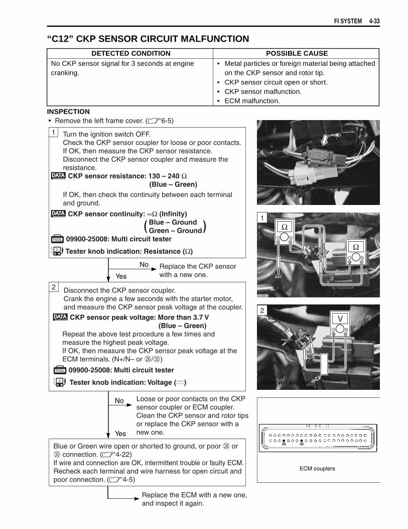
FI SYSTEM 4-33
“C12” CKP SENSOR CIRCUIT MALFUNCTION
INSPECTION
DETECTED CONDITION POSSIBLE CAUSENo CKP sensor signal for 3 seconds at engine cranking.
• Metal particles or foreign material being attached on the CKP sensor and rotor tip.
• CKP sensor circuit open or short.• CKP sensor malfunction.• ECM malfunction.
• Remove the left frame cover. (6-5)
1
2
Yes
Yes
No
No
Replace the CKP sensor with a new one.
Loose or poor contacts on the CKPsensor coupler or ECM coupler.Clean the CKP sensor and rotor tipsor replace the CKP sensor with a new one.
Blue or Green wire open or shorted to ground, or poor or connection. (4-22)If wire and connection are OK, intermittent trouble or faulty ECM.Recheck each terminal and wire harness for open circuit andpoor connection. (4-5)
Turn the ignition switch OFF.Check the CKP sensor coupler for loose or poor contacts.If OK, then measure the CKP sensor resistance. Disconnect the CKP sensor coupler and measure theresistance.
CKP sensor resistance: 130 – 240 Ω(Blue – Green)
If OK, then check the continuity between each terminaland ground.
CKP sensor continuity: ∞Ω (Infinity) Blue – Ground Green – Ground 09900-25008: Multi circuit tester
Tester knob indication: Resistance (Ω)
( )
Disconnect the CKP sensor coupler.Crank the engine a few seconds with the starter motor,and measure the CKP sensor peak voltage at the coupler.
CKP sensor peak voltage: More than 3.7 V (Blue – Green)
Repeat the above test procedure a few times andmeasure the highest peak voltage.If OK, then measure the CKP sensor peak voltage at theECM terminals. (N+/N– or /)
09900-25008: Multi circuit tester
Tester knob indication: Voltage ()
Replace the ECM with a new one, and inspect it again.
Peak volt adapter
V
Peak volt adapterPeak volt adapter
ECM couplers
Ω
Ω1
2
26 30
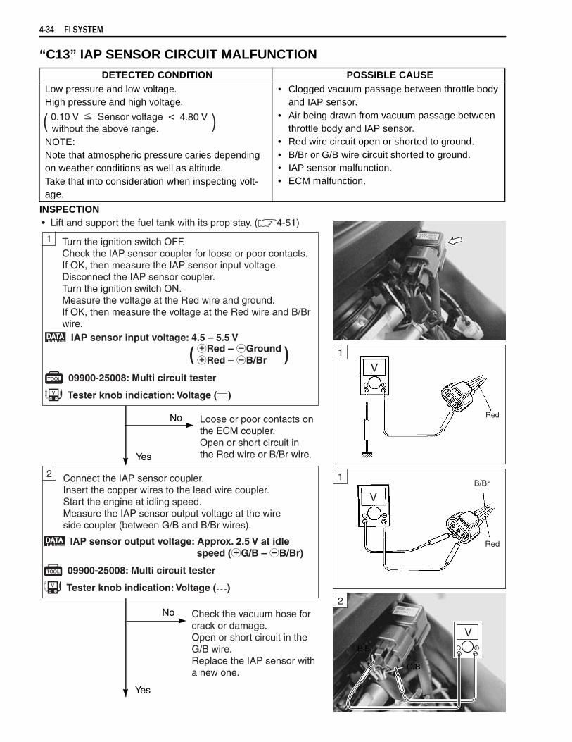
4-34 FI SYSTEM
“C13” IAP SENSOR CIRCUIT MALFUNCTION
INSPECTION
DETECTED CONDITION POSSIBLE CAUSELow pressure and low voltage.High pressure and high voltage.
NOTE:Note that atmospheric pressure caries depending on weather conditions as well as altitude.Take that into consideration when inspecting volt-age.
• Clogged vacuum passage between throttle body and IAP sensor.
• Air being drawn from vacuum passage between throttle body and IAP sensor.
• Red wire circuit open or shorted to ground.• B/Br or G/B wire circuit shorted to ground.• IAP sensor malfunction.• ECM malfunction.
( )0.10 V Sensor voltage 4.80 V<without the above range.
• Lift and support the fuel tank with its prop stay. ( 4-51)
1
2
Yes
Yes
No
No
Turn the ignition switch OFF.Check the IAP sensor coupler for loose or poor contacts.If OK, then measure the IAP sensor input voltage.Disconnect the IAP sensor coupler.Turn the ignition switch ON.Measure the voltage at the Red wire and ground.If OK, then measure the voltage at the Red wire and B/Brwire.
Connect the IAP sensor coupler.Insert the copper wires to the lead wire coupler.Start the engine at idling speed.Measure the IAP sensor output voltage at the wireside coupler (between G/B and B/Br wires).
IAP sensor input voltage: 4.5 – 5.5 V
09900-25008: Multi circuit tester
Tester knob indication: Voltage ( )
( )
Loose or poor contacts on the ECM coupler.Open or short circuit in the Red wire or B/Br wire.
IAP sensor output voltage: Approx. 2.5 V at idle speed ( G/B – B/Br)
09900-25008: Multi circuit tester
Tester knob indication: Voltage ( )
Check the vacuum hose forcrack or damage.Open or short circuit in theG/B wire.Replace the IAP sensor witha new one.
V
G/BG/B
B/BrB/Br
Red
1
1
2
Red – GroundRed – B/Br
V
V

FI SYSTEM 4-35
OUTPUT VOLTAGE (VCC VOLTAGE 4.5 – 5.0 V, AMBIENT TEMP. 20 – 30 °C, 68 – 86 °F)
ALTITUDE(Reference)
ATMOSPHERICPRESSURE
OUTPUTVOLTAGE
(ft) (m) (mmHg) kPa (V)0
2 000
0
610
760
707
10094
3.4 – 4.0
2 001
5 000
611
1 524
707
634
9485
3.0 – 3.7
5 001
8 000
1 525
2 438
634
567
8576
2.6 – 3.4
8 001
10 000
2 439
3 048
567
526
7670
2.4 – 3.1
3
Yes
No If check result is not satis-factory, replace IAP sensorwith a new one.
Red, G/B or B/Br wire open or shorted to ground, or poor , or connection. ( 4-22)
If wire and connection are OK, intermittent trouble or faultyECM.Recheck each terminal and wire harness for open circuit andpoor connection. ( 4-5)
Remove the IAP sensor.Connect the vacuum pump gauge to the vacuum port ofthe IAP sensor.Arrange 3 new 1.5 V batteries in series (check that totalvoltage is 4.5 – 5.0 V) and connect terminal to theground terminal and terminal to the Vcc terminal.Check the voltage between Vout and ground. Also, checkif voltage reduces when vacuum is applied up to 40 cmHgby using vacuum pump gauge. (See table below.)
09917-47010: Vacuum pump gauge 09900-25008: Multi circuit tester
Tester knob indication: Voltage ( )
Replace the ECM with a newone, and inspect it again.
ECM coupler
3

4-36 FI SYSTEM
“C14” TP SENSOR CIRCUIT MALFUNCTION
INSPECTION
DETECTED CONDITION POSSIBLE CAUSE
Signal voltage low or high.Difference between actual throttle opening and open-ing calculated by ECM in larger than specified value.
• TP sensor maladjusted.• TP sensor circuit open or short.• TP sensor malfunction.• ECM malfunction.( )0.10 V Sensor voltage 4.80 V<
without the above range.
Turn the ignition switch OFF.Check the TP sensor coupler for loose or poor contacts.If OK, then measure the TP sensor input voltage.Disconnect the TP sensor/injector coupler .Turn the ignition switch ON.Measure the voltage at the Red wire and ground.If OK, then measure the voltage at the Red wire and B/Brwire.
• Remove the fuel tank and air cleaner box. (4-52 and -60)
1
2
Yes
Yes
No
No Reset the TP sensorposition correctly.Replace the TP sensor with a new one.
TP sensor input voltage: 4.5 – 5.5 V Red – Ground Red – B/Br
09900-25008: Multi circuit tester
Tester knob indication: Voltage (-)
( )
Loose or poor contacts on the ECM coupler.Open or short circuit in the Red wire or B/Br wire.
Turn the ignition switch OFF.Disconnect the TP sensor/injector coupler.Check the continuity between P/W wire and ground. TP sensor continuity: ∞Ω (Infinity) (P/W – Ground)
If OK, then measure the TP sensor resistance at thecoupler (between P/W and B/Br wires).Turn the throttle grip and measure the resistance. TP sensor resistance Throttle valve is closed : Approx. 1.1 kΩ Throttle valve is opened: Approx. 4.3 kΩ
09900-25008: Multi circuit tester
Tester knob indication: Resistance (Ω)
V
Ω
Ω
GroundGround
B/BrB/BrP/WP/W
RR
B/BrB/Br
GroundGround
1
1
2

FI SYSTEM 4-37
3
Yes
No
Red, P/W or B/Br wire open or shorted to ground, or poor , or connection. (4-22)If wire and connection are OK, intermittent trouble or faultyECM.Recheck each terminal and wire harness for open circuitand poor connection. (4-5)
Replace the ECM with a new one,and inspect it again.
Connect the TP sensor/injector coupler .Insert the copper wires to the lead wire coupler.Turn the ignition switch ON.Measure the TP sensor output voltage at the coupler(between P/W and B/Br wires) by turning the throttle grip.
TP sensor output voltage Throttle valve is closed : Approx. 1.1 V Throttle valve is opened: Approx. 4.3 V
09900-25008: Multi circuit tester
Tester knob indication: Voltage ()
If check result is not satisfactory, replace TP sensor with a new one.
VP/WP/W
B/BrB/Br
ECM coupler
3
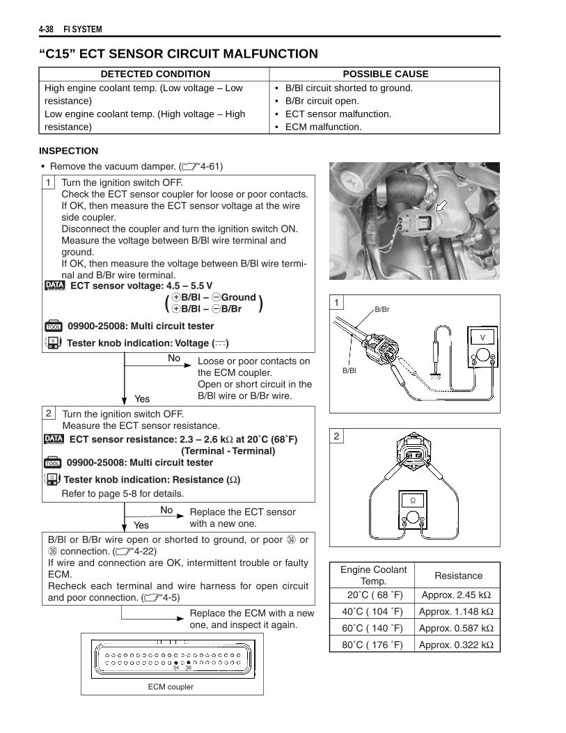
4-38 FI SYSTEM
“C15” ECT SENSOR CIRCUIT MALFUNCTION
INSPECTION
DETECTED CONDITION POSSIBLE CAUSEHigh engine coolant temp. (Low voltage – Low resistance)Low engine coolant temp. (High voltage – High resistance)
• B/Bl circuit shorted to ground.• B/Br circuit open.• ECT sensor malfunction.• ECM malfunction.
• Remove the vacuum damper. (4-61)
1
2
Yes
Yes
No
No
Turn the ignition switch OFF.Measure the ECT sensor resistance.
ECT sensor voltage: 4.5 – 5.5 VB/Bl – GroundB/Bl – B/Br
09900-25008: Multi circuit tester
Tester knob indication: Voltage ()
( )
Loose or poor contacts on the ECM coupler.Open or short circuit in theB/Bl wire or B/Br wire.
ECT sensor resistance: 2.3 – 2.6 kΩ at 20˚C (68˚F) (Terminal - Terminal)
09900-25008: Multi circuit tester
Tester knob indication: Resistance (Ω)
Replace the ECT sensor with a new one.
Replace the ECM with a newone, and inspect it again.
Turn the ignition switch OFF.Check the ECT sensor coupler for loose or poor contacts.If OK, then measure the ECT sensor voltage at the wireside coupler.Disconnect the coupler and turn the ignition switch ON.Measure the voltage between B/Bl wire terminal andground.If OK, then measure the voltage between B/Bl wire termi-nal and B/Br wire terminal.
Refer to page 5-8 for details.
Engine CoolantTemp. Resistance
20˚C ( 68 ˚F) Approx. 2.45 kΩ
40˚C ( 104 ˚F) Approx. 1.148 kΩ
60˚C ( 140 ˚F) Approx. 0.587 kΩ
80˚C ( 176 ˚F) Approx. 0.322 kΩ
ECM coupler
B/Br
B/Bl
V
1
2
B/Bl or B/Br wire open or shorted to ground, or poor or connection. (4-22)If wire and connection are OK, intermittent trouble or faultyECM.Recheck each terminal and wire harness for open circuitand poor connection. (4-5)

FI SYSTEM 4-39
“C21” IAT SENSOR CIRCUIT MALFUNCTION
INSPECTION
DETECTED CONDITION POSSIBLE CAUSEHigh intake air temp. (Low voltage – Low resis-tance)Low intake air temp. (High voltage – High resis-tance)
• Dg circuit shorted to ground.• B/Br circuit open.• IAT sensor malfunction.• ECM malfunction.
• Lift and support the fuel tank with its prop stay. (4-51)
1
2
Yes
Yes
No
No
Turn the ignition switch OFF.Measure the IAT sensor resistance.
IAT sensor voltage: 4.5 – 5.5 VDg – GroundDg – B/Br
09900-25008: Multi circuit tester
Tester knob indication: Voltage ()
( )
Loose or poor contacts on the ECM coupler.Open or short circuit in theDg wire or B/Br wire.
IAT sensor resistance: 2.3 – 2.6 kΩ at 20˚C (68˚F) (Terminal – Terminal)
09900-25008: Multi circuit tester
Tester knob indication: Resistance (Ω)
Replace the IAT sensor with a new one.
Replace the ECM with a newone, and inspect it again.
Turn the ignition switch OFF.Check the IAT sensor coupler for loose or poor contacts.If OK, then measure the IAT sensor voltage at the wireside coupler.Disconnect the coupler and turn the ignition switch ON.Measure the voltage between Dg wire terminal andground.If OK, then measure the voltage between Dg wire termi-nal and B/Br wire terminal.
Intake AirTemp. Resistance
20˚C ( 68 ˚F) Approx. 2.45 kΩ
40˚C ( 104 ˚F) Approx. 1.148 kΩ
60˚C ( 140 ˚F) Approx. 0.587 kΩ
80˚C ( 176 ˚F) Approx. 0.322 kΩ
B/Br
Dg
V
ECM coupler
1
2
NOTE:IAT sensor resistance measurementmethod is the same way as that of theECT sensor. Refer to page 5-10 fordetails.
Dg or B/Br wire open or shorted to ground, or poor or connection. (4-22)If wire and connection are OK, intermittent trouble or faultyECM.Recheck each terminal and wire harness for open circuitand poor connection. (4-5)
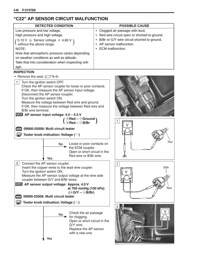
4-40 FI SYSTEM
“C22” AP SENSOR CIRCUIT MALFUNCTION
INSPECTION
DETECTED CONDITION POSSIBLE CAUSELow pressure and low voltage.High pressure and high voltage.
NOTE:Note that atmospheric pressure caries depending on weather conditions as well as altitude.Take that into consideration when inspecting volt-age.
• Clogged air passage with dust.• Red wire circuit open or shorted to ground.• B/Br or G/Y wire circuit shorted to ground.• AP sensor malfunction.• ECM malfunction.
( )0.10 V Sensor voltage 4.80 V<without the above range.
AP sensor input voltage: 4.5 – 5.5 VRed – GroundRed – B/Br
09900-25008: Multi circuit tester
Tester knob indication: Voltage ()
( )
• Remove the seat. (6-4)
1
2
Yes
Yes
No
No
Loose or poor contacts on the ECM coupler.Open or short circuit in theRed wire or B/Br wire.
AP sensor output voltage: Approx. 4.0 V at 760 mmHg (100 kPa)
(G/Y – B/Br) 09900-25008: Multi circuit tester
Tester knob indication: Voltage ()
Check the air passage for clogging.Open or short circuit in theG/Y wire.Replace the AP sensorwith a new one.
Turn the ignition switch OFF.Check the AP sensor coupler for loose or poor contacts.If OK, then measure the AP sensor input voltage.Disconnect the AP sensor coupler.Turn the ignition switch ON.Measure the voltage between Red wire and ground.If OK, then measure the voltage between Red wire andB/Br wire terminal.
Connect the AP sensor coupler.Insert the copper wires to the lead wire coupler.Turn the ignition switch ON.Measure the AP sensor output voltage at the wire sidecoupler between G/Y and B/Br wires.
Red
1
1
V
B/Br
G/Y
2
V
V

FI SYSTEM 4-41
OUTPUT VOLTAGE (VCC VOLTAGE 4.5 – 5.0 V, AMBIENT TEMP. 20 – 30 °C, 68 – 86 °F)
ALTITUDE(Reference)
ATMOSPHERICPRESSURE
OUTPUTVOLTAGE
(ft) (m) (mmHg) kPa (V)0
2 000
0
610
760
707
10094
3.4 – 4.0
2 001
5 000
611
1 524
707
634
9485
3.0 – 3.7
5 001
8 000
1 525
2 438
634
567
8576
2.6 – 3.4
8 001
10 000
2 439
3 048
567
526
7670
2.4 – 3.1
3
Yes
No If check result is not satisfactory,replace AP sensor with a new one.
Red, G/Y or B/Br wire open or shorted to ground, or poor , or connection. ( 4-22)
If wire and connection are OK, intermittent trouble or faultyECM.Recheck each terminal and wire harness for open circuit andpoor connection. ( 4-5)
Remove the AP sensor.Connect the vacuum pump gauge to the air passage portof the AP sensor.Arrange 3 new 1.5 V batteries in series (check that totalvoltage is 4.5 – 5.0 V) and connect terminal to theground terminal and terminal to the Vcc terminal.Check the voltage between vout and ground. Also, checkif voltage reduces when vacuum is applied up to 40 cmHgby using vacuum pump gauge. (See table below.)
09917-47010: Vacuum pump gauge 09900-25008: Multi circuit tester
Tester knob indication: Voltage ( )
Replace the ECM with a newone, and inspect it again.
ECM coupler
3
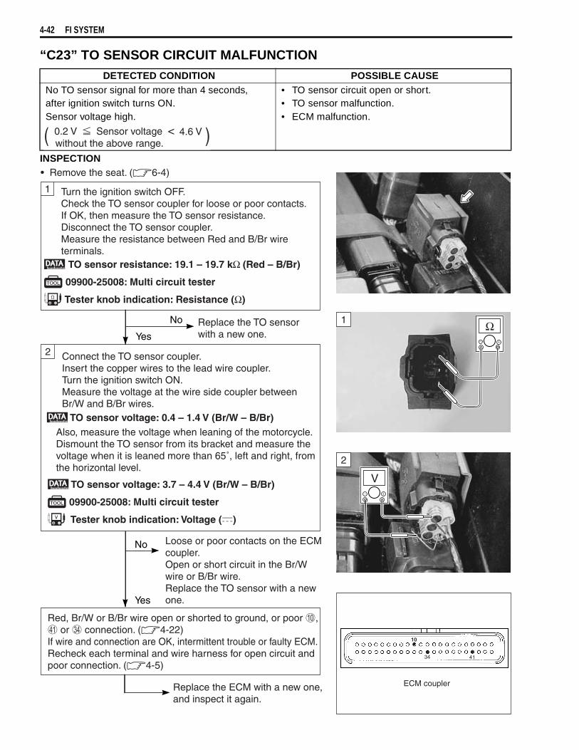
4-42 FI SYSTEM
“C23” TO SENSOR CIRCUIT MALFUNCTION
INSPECTION
DETECTED CONDITION POSSIBLE CAUSENo TO sensor signal for more than 4 seconds,after ignition switch turns ON.Sensor voltage high.
• TO sensor circuit open or short.• TO sensor malfunction.• ECM malfunction.
( )0.2 V Sensor voltage 4.6 V<without the above range.
Ω
• Remove the seat. (6-4)
1
2
Yes
Yes
No
No
Replace the TO sensor with a new one.
Loose or poor contacts on the ECMcoupler.Open or short circuit in the Br/Wwire or B/Br wire.Replace the TO sensor with a newone.
Red, Br/W or B/Br wire open or shorted to ground, or poor , or connection. (4-22)If wire and connection are OK, intermittent trouble or faulty ECM.Recheck each terminal and wire harness for open circuit andpoor connection. (4-5)
Turn the ignition switch OFF.Check the TO sensor coupler for loose or poor contacts.If OK, then measure the TO sensor resistance. Disconnect the TO sensor coupler.Measure the resistance between Red and B/Br wireterminals.
TO sensor resistance: 19.1 – 19.7 kΩ (Red – B/Br)
09900-25008: Multi circuit tester
Tester knob indication: Resistance (Ω)
Connect the TO sensor coupler.Insert the copper wires to the lead wire coupler.Turn the ignition switch ON.Measure the voltage at the wire side coupler betweenBr/W and B/Br wires. TO sensor voltage: 0.4 – 1.4 V (Br/W – B/Br)
TO sensor voltage: 3.7 – 4.4 V (Br/W – B/Br)
09900-25008: Multi circuit tester
Tester knob indication: Voltage ()
Replace the ECM with a new one, and inspect it again.
Also, measure the voltage when leaning of the motorcycle.Dismount the TO sensor from its bracket and measure thevoltage when it is leaned more than 65˚, left and right, fromthe horizontal level.
V
1
2
ECM coupler
10
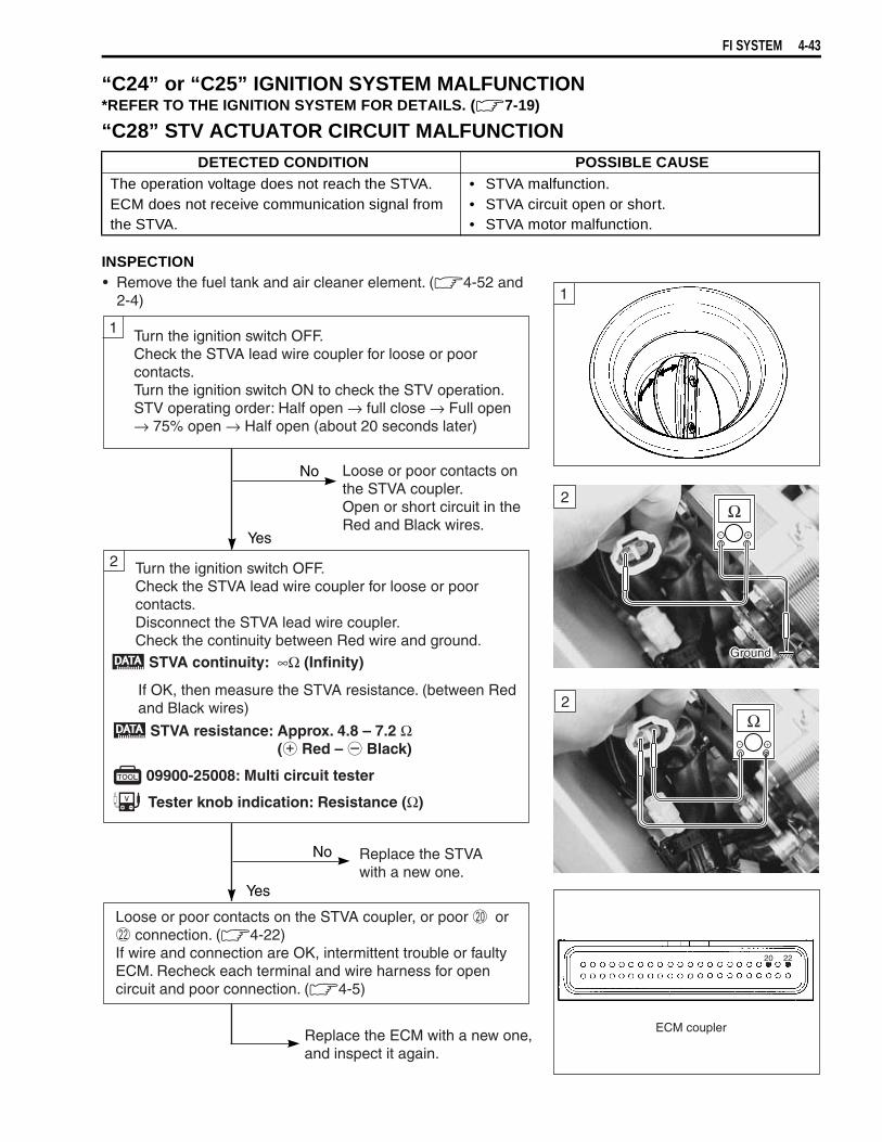
FI SYSTEM 4-43
“C24” or “C25” IGNITION SYSTEM MALFUNCTION*REFER TO THE IGNITION SYSTEM FOR DETAILS. ( 7-19)
“C28” STV ACTUATOR CIRCUIT MALFUNCTION
INSPECTION
DETECTED CONDITION POSSIBLE CAUSEThe operation voltage does not reach the STVA.ECM does not receive communication signal from the STVA.
• STVA malfunction.• STVA circuit open or short.• STVA motor malfunction.
• Remove the fuel tank and air cleaner element. ( 4-52 and2-4)
1
2
Yes
Yes
No
No
Loose or poor contacts onthe STVA coupler.Open or short circuit in theRed and Black wires.
Replace the STVAwith a new one.
Turn the ignition switch OFF.Check the STVA lead wire coupler for loose or poorcontacts.Turn the ignition switch ON to check the STV operation.STV operating order: Half open → full close → Full open → 75% open → Half open (about 20 seconds later)
Turn the ignition switch OFF.Check the STVA lead wire coupler for loose or poorcontacts.Disconnect the STVA lead wire coupler.Check the continuity between Red wire and ground.
STVA continuity: ∞Ω (Infinity)
STVA resistance: Approx. 4.8 – 7.2 Ω ( Red – Black)
09900-25008: Multi circuit tester
Tester knob indication: Resistance (Ω)
Replace the ECM with a new one, and inspect it again.
If OK, then measure the STVA resistance. (between Redand Black wires)
Loose or poor contacts on the STVA coupler, or poor or connection. ( 4-22)
If wire and connection are OK, intermittent trouble or faultyECM. Recheck each terminal and wire harness for opencircuit and poor connection. ( 4-5)
ECM coupler
Ω
Ω
2
1
2
Ground

4-44 FI SYSTEM
“C29” STP SENSOR CIRCUIT MALFUNCTION
INSPECTION
DETECTED CONDITION POSSIBLE CAUSESignal voltage low or high.Difference between actual throttle opening andopening calculated by ECM in larger than specifiedvalue.
• STP sensor maladjusted.• STP sensor circuit open or short.• STP sensor malfunction.• ECM malfunction.
( )0.10 V Sensor voltage 4.80 V<without the above range.
• Remove the fuel tank and air cleaner box. (4-52 and -60)
1
2
Yes
No
No Reset the STP sensor position correctly.(4-68)Replace the STP sensorwith a new one.
Turn the ignition switch OFF.Check the STP sensor coupler for loose or poor contacts.If OK, then measure the STP sensor input voltage. Disconnect the STP sensor coupler.Turn the ignition switch ON.Measure the voltage at the Red wire and ground.If OK, then measure the voltage at the Red wire and B/Brwire.
STP sensor input voltage: 4.5 – 5.5 VRed – GroundRed – B/Br
09900-25008: Multi circuit tester
Tester knob indication: Voltage ()
Turn the ignition switch OFF.Disconnect the STP sensor coupler.Check the continuity between T3 terminal wire and ground.
STP sensor continuity: ∞Ω (Infinity) (T3 terminal – Ground)
STP sensor resistanceSecondary throttle valve is closed : Approx. 1.1 kΩ
Secondary throttle valve is opened: Approx. 4.3 kΩ
09900-25008: Multi circuit tester
Tester knob indication: Resistance (Ω)
If OK, then measure the STP sensor resistance at thecoupler (between T3 and T4 terminals).Close and open the secondary throttle valve by finger, andmeasure the valve closing and opening resistance.
( )
Loose or poor contacts on the ECM coupler.Open or short circuit in the Red wire or B/Br wire.
V
Red
B/Br
Ground
Ω
Ground
T3
Ω
T3
T4
1
2
2
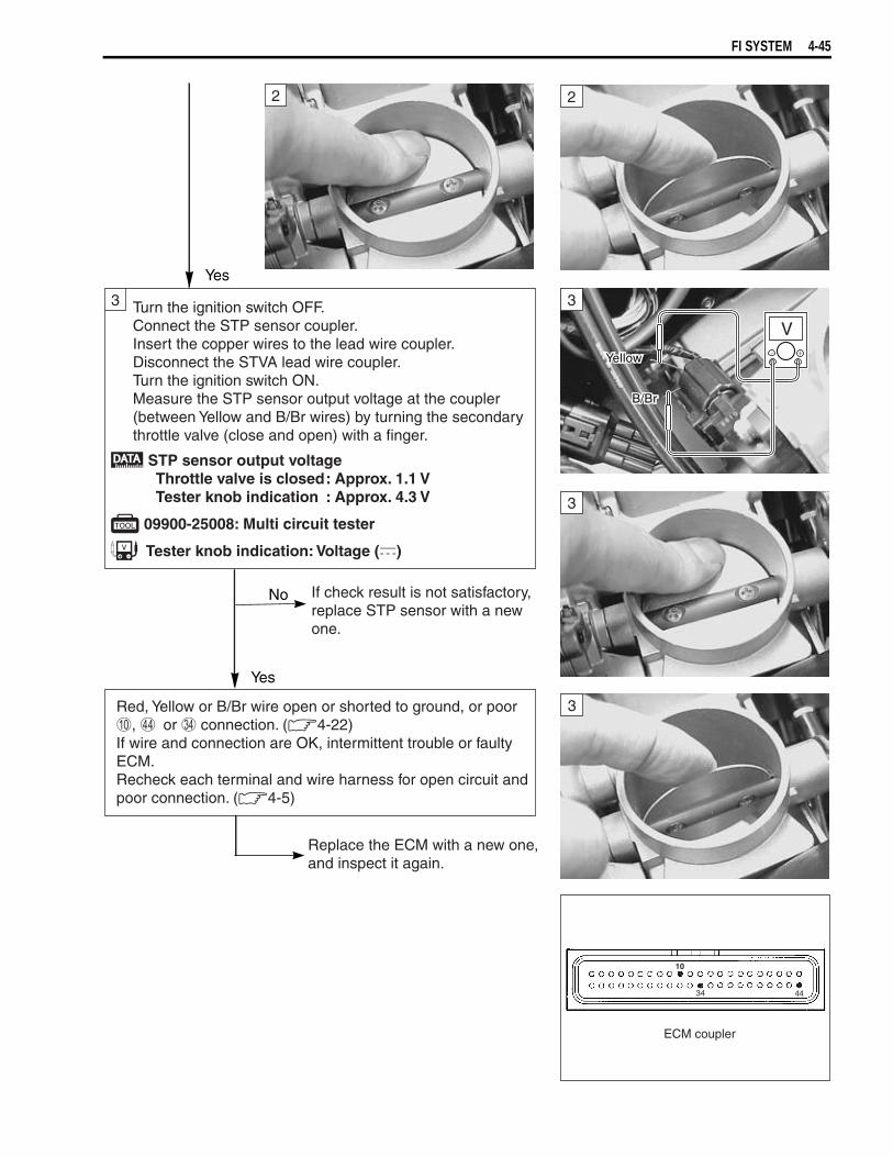
FI SYSTEM 4-45
3
Yes
Yes
No If check result is not satisfactory, replace STP sensor with a newone.
Turn the ignition switch OFF.Connect the STP sensor coupler.Insert the copper wires to the lead wire coupler.Disconnect the STVA lead wire coupler.Turn the ignition switch ON.Measure the STP sensor output voltage at the coupler(between Yellow and B/Br wires) by turning the secondarythrottle valve (close and open) with a finger.
STP sensor output voltage Throttle valve is closed: Approx. 1.1 V Tester knob indication : Approx. 4.3 V
09900-25008: Multi circuit tester
Tester knob indication: Voltage ()
Red, Yellow or B/Br wire open or shorted to ground, or poor, or connection. (4-22)If wire and connection are OK, intermittent trouble or faultyECM.Recheck each terminal and wire harness for open circuit andpoor connection. (4-5)
Replace the ECM with a new one,and inspect it again.
ECM coupler
10
V
Yellow
B/Br
2 2
3
3
3

4-46 FI SYSTEM
“C31” GEAR POSITION (GP) SWITCH CIRCUIT MALFUNCTION
INSPECTION
DETECTED CONDITION POSSIBLE CAUSENo Gear Position switch voltageSwitch voltage low.
• Gear Position switch circuit open or short.• Gear Position switch malfunction.• ECM malfunction.( )Switch Voltage > 1.0 V
without the above value.
• Lift and support the fuel tank with its prop stay. (4-51)
1
Yes
No
Turn the ignition switch OFF.Check the GP switch coupler for loose or poor contacts.If OK, then measure the GP switch voltage.Support the motorcycle with a jack.Turn the side-stand to up-right position.Turn the engine stop switch ON.Insert the copper wire to the lead wire coupler.Turn the ignition switch ON.Measure the voltage at the wire side coupler betweenPink wire and ground, when shifting the gearshift leverfrom 1st to Top.
GP switch voltage: More than 1.0 V (Pink – Ground)
09900-25008: Multi circuit tester
Tester knob indication: Voltage ()
Open or short circuit in the Pink wire.Replace the GP switch with a new one.
Pink wire open or shorted to ground, or poor connection.(4-22)If wire and connection are OK, intermittent trouble or faulty ECM.Recheck each terminal and wire harness for open circuit andpoor connection. (4-5)
Replace the ECM with a new one, and inspect it again.
ECM coupler
V
Ground
Pink
1

FI SYSTEM 4-47
“C32” or “C33” FUEL INJECTION MALFUNCTION
INSPECTION
DETECTED CONDITION POSSIBLE CAUSENo injector current. • Injector circuit open or short.
• Injector malfunction.• ECM malfunction.
• Remove the fuel tank and air cleaner box. (4-52 and -60)
1
2
Yes
Yes
No
No Open circuit in the Yellow/Red wire.
Turn the ignition switch OFF.Check the injector coupler for loose or poor contacts.If OK, then measure the injector resistance.Disconnect the TP sensor/injector coupler and measurethe resistance between lead wires.
Turn the ignition switch ON.Measure the injector voltage between Y/R wire andground.
Injector voltage: Battery voltage(Y/R – Ground)
09900-25008: Multi circuit tester
Tester knob indication: Voltage ()
Replace the ECM with a new one, and inspect it again.
Injector resistance: 12 – 18 Ω at 20˚C (68˚F)
Injector continuity: ∞Ω (Infinity) (Y/R – Ground)
09900-25008: Multi circuit tester
Tester knob indication: Resistance (Ω)
If OK, then check the continuity between Y/R wireand ground.
No.1 : Y/R – Gr/WNo. 2 : Y/R – Gr/B( )
Replace the injector with a new one. ( 4-67)
NOTE:Injector voltage can be detected only 3 seconds afterignition switch is turned ON.
Gr/W, Gr/B or Y/R wire open or shorted to ground, or poor , or connection. (4-22)If wire and connection are OK, intermittent trouble or faultyECM.Recheck each terminal and wire harness for open circuit andpoor connection. (4-5) ECM coupler
Ω
Ground
Y/R
GroundGround
Gr/B
Gr/W
V
GroundGroundGround
Y/R
1
2
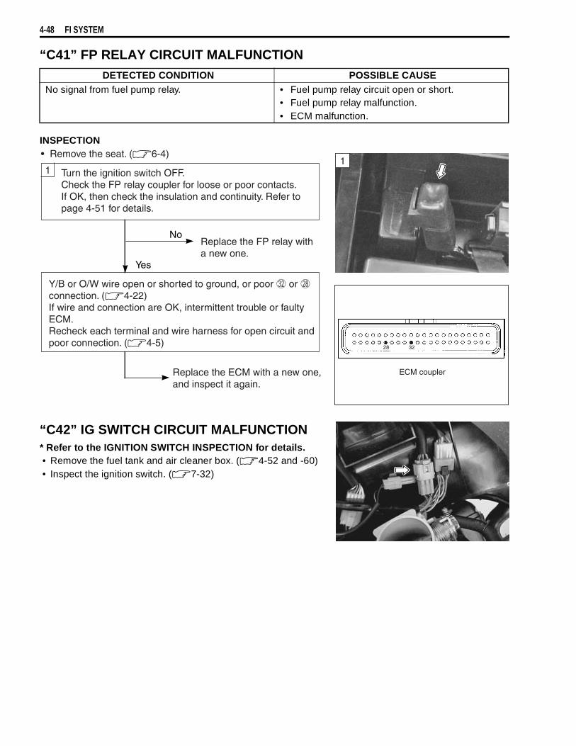
4-48 FI SYSTEM
“C41” FP RELAY CIRCUIT MALFUNCTION
INSPECTION
“C42” IG SWITCH CIRCUIT MALFUNCTION* Refer to the IGNITION SWITCH INSPECTION for details. • Remove the fuel tank and air cleaner box. ( 4-52 and -60)• Inspect the ignition switch. ( 7-32)
DETECTED CONDITION POSSIBLE CAUSENo signal from fuel pump relay. • Fuel pump relay circuit open or short.
• Fuel pump relay malfunction.• ECM malfunction.
• Remove the seat. (6-4)
1
Yes
No
Turn the ignition switch OFF.Check the FP relay coupler for loose or poor contacts.If OK, then check the insulation and continuity. Refer topage 4-51 for details.
Y/B or O/W wire open or shorted to ground, or poor or connection. (4-22)If wire and connection are OK, intermittent trouble or faultyECM.Recheck each terminal and wire harness for open circuit andpoor connection. (4-5)
Replace the ECM with a new one, and inspect it again.
Replace the FP relay witha new one.
ECM coupler
1

FI SYSTEM 4-49
“C44” HO2 SENSOR (HO2S) CIRCUIT MALFUNCTION
INSPECTION• Remove the engine under cover and seat. ( 3-3 and 6-4)
DETECTED CONDITION POSSIBLE CAUSEOutput voltage of HO2 Sensor higher than the spec-ification or lower than the specification.
• HO2 sensor or its circuit open or short.• Fuel system malfunction.• ECM malfunction.
1 Turn the ignition switch OFF.Check the HO2 sensor coupler for loose or poor contacts.If OK, then check the continuity.Disconnect the HO2 sensor coupler and ECM coupler.Check the continuity between the HO2 sensor coupler terminal (White/Green) and ECM coupler terminal (White/Green).Also, check the infinity between the HO2 sensor coupler terminal and ground.
No
Yes
Loose or poor contacts on theECM coupler.Open or short circuit in the White/Green wire.
NoReplace the HO2 sensor witha new one.
2 Connect the HO2 sensor coupler and ECM coupler.Insert the copper wires to the HO2 sensor lead wire coupler.Start the engine and warm up the engine up to enginecoolant temperature is 80 ˚C (176 ˚F).Measure the HO2 sensor output voltage at the coupler(between White/Green and Black/Brown wires) when idlingcondition.Also, measure the HO2 sensor output voltage while holdingthe engine speed at 5 000 r/min.
1
2
ECM coupler
Ground
HO2Scoupler
W/G
V
09900-25008: Multi circuit tester
Tester knob indication: Continuity ()
HO2 sensor output voltage at idle speed: less than 0.4 V ( W/G – B/Br)HO2 sensor output voltage at 5 000 r/min: more than 0.6 V ( W/G – B/Br)
09900-25008: Multi circuit tester
Tester knob indication: Voltage ()
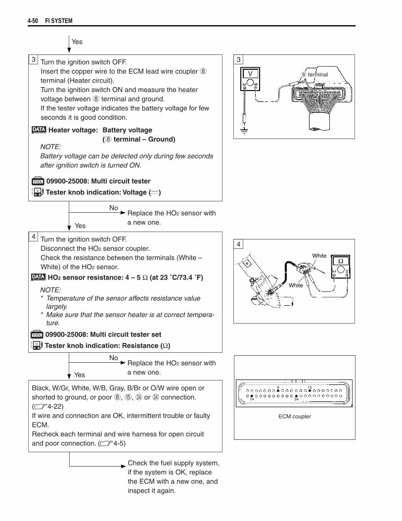
4-50 FI SYSTEM
White
WhiteΩ
V terminal
33
4
No
Yes
Yes
Replace the HO2 sensor witha new one.
No
Yes
Replace the HO2 sensor witha new one.
4 Turn the ignition switch OFF.Disconnect the HO2 sensor coupler.Check the resistance between the terminals (White –White) of the HO2 sensor.
Check the fuel supply system,if the system is OK, replace the ECM with a new one, and inspect it again.
Turn the ignition switch OFF.Insert the copper wire to the ECM lead wire coupler terminal (Heater circuit).Turn the ignition switch ON and measure the heatervoltage between terminal and ground.If the tester voltage indicates the battery voltage for fewseconds it is good condition.
NOTE:* Temperature of the sensor affects resistance value
largely.* Make sure that the sensor heater is at correct tempera-
ture.
09900-25008: Multi circuit tester set
Tester knob indication: Resistance (Ω)
HO2 sensor resistance: 4 – 5 Ω (at 23 ˚C/73.4 ˚F)
Heater voltage: Battery voltage( terminal – Ground)
NOTE:Battery voltage can be detected only during few secondsafter ignition switch is turned ON.
09900-25008: Multi circuit tester
Tester knob indication: Voltage ( )
ECM coupler
Black, W/Gr, White, W/B, Gray, B/Br or O/W wire open or shorted to ground, or poor , , or connection. ( 4-22)If wire and connection are OK, intermittent trouble or faulty ECM.Recheck each terminal and wire harness for open circuit and poor connection. ( 4-5)
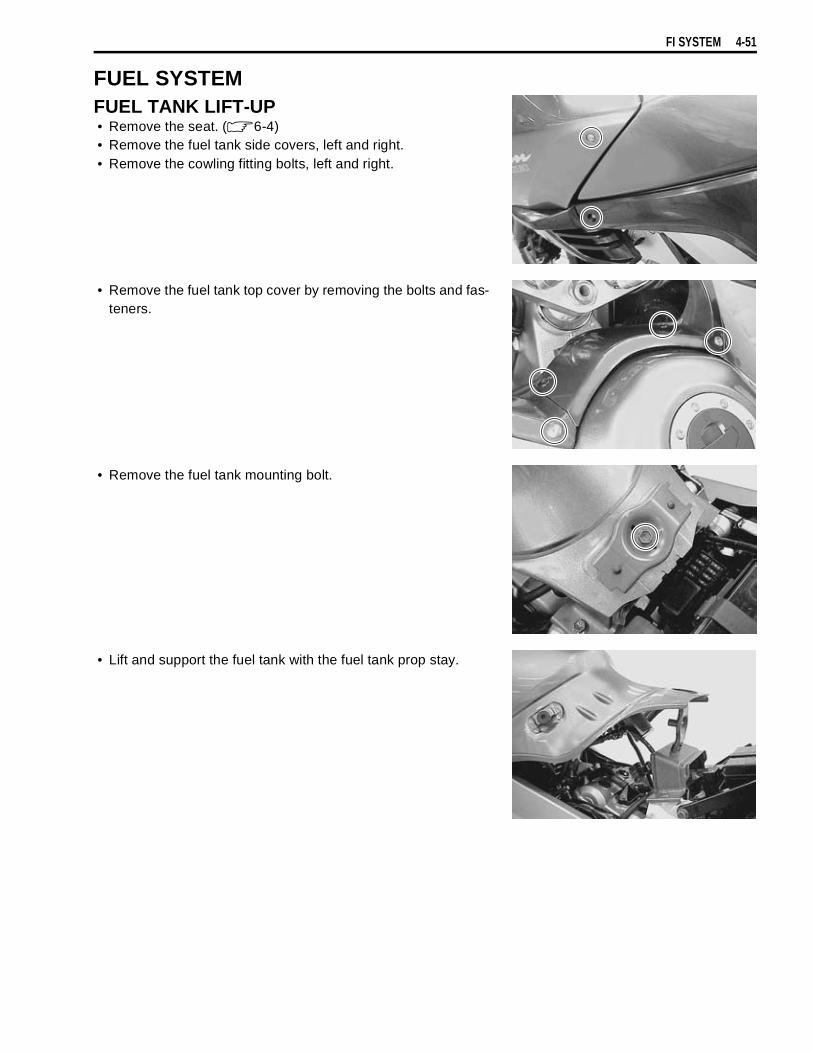
FI SYSTEM 4-51
FUEL SYSTEMFUEL TANK LIFT-UP• Remove the seat. ( 6-4)• Remove the fuel tank side covers, left and right.• Remove the cowling fitting bolts, left and right.
• Remove the fuel tank top cover by removing the bolts and fas-teners.
• Remove the fuel tank mounting bolt.
• Lift and support the fuel tank with the fuel tank prop stay.
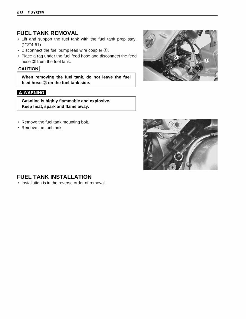
4-52 FI SYSTEM
FUEL TANK REMOVAL• Lift and support the fuel tank with the fuel tank prop stay.
( 4-51)• Disconnect the fuel pump lead wire coupler
.• Place a rag under the fuel feed hose and disconnect the feed
hose
from the fuel tank.
• Remove the fuel tank mounting bolt.• Remove the fuel tank.
FUEL TANK INSTALLATION• Installation is in the reverse order of removal.
When removing the fuel tank, do not leave the fuelfeed hose
on the fuel tank side.
Gasoline is highly flammable and explosive.Keep heat, spark and flame away.
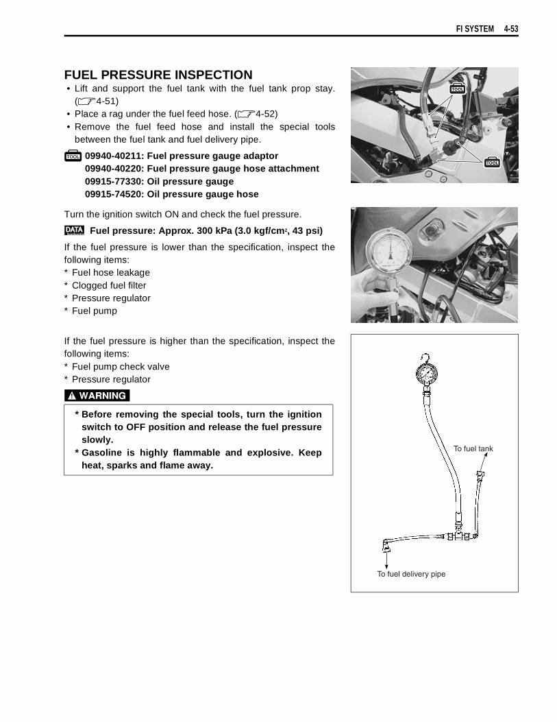
FI SYSTEM 4-53
FUEL PRESSURE INSPECTION• Lift and support the fuel tank with the fuel tank prop stay.
( 4-51)• Place a rag under the fuel feed hose. ( 4-52)• Remove the fuel feed hose and install the special tools
between the fuel tank and fuel delivery pipe.
09940-40211: Fuel pressure gauge adaptor09940-40220: Fuel pressure gauge hose attachment09915-77330: Oil pressure gauge09915-74520: Oil pressure gauge hose
Turn the ignition switch ON and check the fuel pressure.
Fuel pressure: Approx. 300 kPa (3.0 kgf/cm2, 43 psi)
If the fuel pressure is lower than the specification, inspect thefollowing items:* Fuel hose leakage* Clogged fuel filter* Pressure regulator* Fuel pump
If the fuel pressure is higher than the specification, inspect thefollowing items:* Fuel pump check valve* Pressure regulator
* Before removing the special tools, turn the ignitionswitch to OFF position and release the fuel pressureslowly.
* Gasoline is highly flammable and explosive. Keepheat, sparks and flame away.
To fuel tank
To fuel delivery pipe
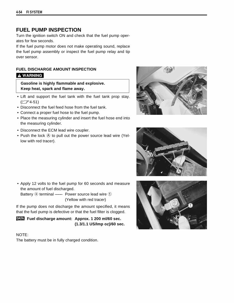
4-54 FI SYSTEM
FUEL PUMP INSPECTIONTurn the ignition switch ON and check that the fuel pump oper-ates for few seconds.If the fuel pump motor does not make operating sound, replacethe fuel pump assembly or inspect the fuel pump relay and tipover sensor.
FUEL DISCHARGE AMOUNT INSPECTION
• Lift and support the fuel tank with the fuel tank prop stay.( 4-51)
• Disconnect the fuel feed hose from the fuel tank.• Connect a proper fuel hose to the fuel pump.• Place the measuring cylinder and insert the fuel hose end into
the measuring cylinder.
• Disconnect the ECM lead wire coupler.• Push the lock
to pull out the power source lead wire (Yel-low with red tracer).
• Apply 12 volts to the fuel pump for 60 seconds and measurethe amount of fuel discharged.Battery
terminal –––– Power source lead wire
(Yellow with red tracer)
If the pump does not discharge the amount specified, it meansthat the fuel pump is defective or that the fuel filter is clogged.
Fuel discharge amount: Approx. 1 200 ml/60 sec.(1.3/1.1 US/Imp oz)/60 sec.
NOTE:The battery must be in fully charged condition.
Gasoline is highly flammable and explosive. Keep heat, spark and flame away.
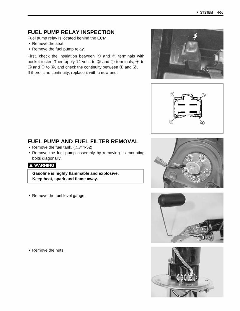
FI SYSTEM 4-55
FUEL PUMP RELAY INSPECTIONFuel pump relay is located behind the ECM.• Remove the seat.• Remove the fuel pump relay.
First, check the insulation between
and
terminals withpocket tester. Then apply 12 volts to
and
terminals,
to
and
to
, and check the continuity between
and
.If there is no continuity, replace it with a new one.
FUEL PUMP AND FUEL FILTER REMOVAL• Remove the fuel tank. ( 4-52)• Remove the fuel pump assembly by removing its mounting
bolts diagonally.
• Remove the fuel level gauge.
• Remove the nuts.
Gasoline is highly flammable and explosive. Keep heat, spark and flame away.
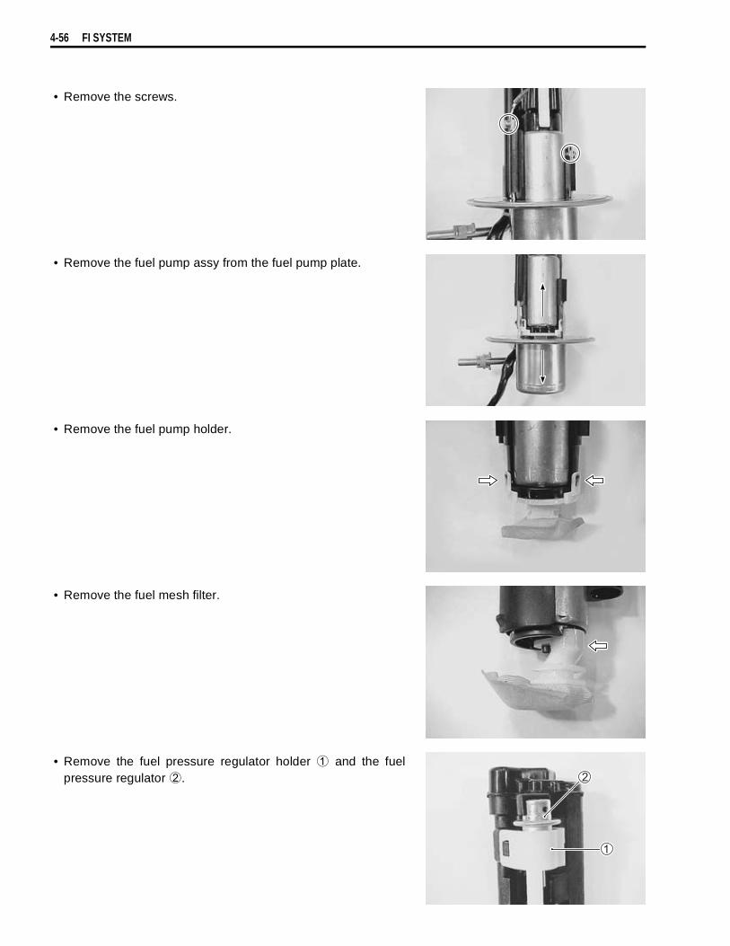
4-56 FI SYSTEM
• Remove the screws.
• Remove the fuel pump assy from the fuel pump plate.
• Remove the fuel pump holder.
• Remove the fuel mesh filter.
• Remove the fuel pressure regulator holder
and the fuelpressure regulator
.

FI SYSTEM 4-57
FUEL MESH FILTER INSPECTION AND CLEANINGIf the fuel mesh filter is clogged with sediment or rust, fuel willnot flow smoothly and loss in engine power may result. Blow the fuel mesh filter with compressed air.
NOTE:If the fuel mesh filter is clogged with many sediment or rust,replace the fuel filter cartridge with a new one.
FUEL PUMP AND FUEL MESH FILTER INSTALLATIONInstall the fuel pump and fuel mesh filter in the reverse order ofremoval, and pay attention to the following points:• Install the new O-rings to the fuel pressure regulator and fuel
pipe.• Apply thin coat of the engine oil to the O-rings.
• Tighten the screws together with the lead wire terminals.
• Tighten the nuts together with the lead wire terminals.
......
terminal for fuel pump
......
terminal for fuel level gauge
......
terminal for fuel level gauge
• Install the fuel level gauge.
Use the new O-rings to prevent fuel leakage.
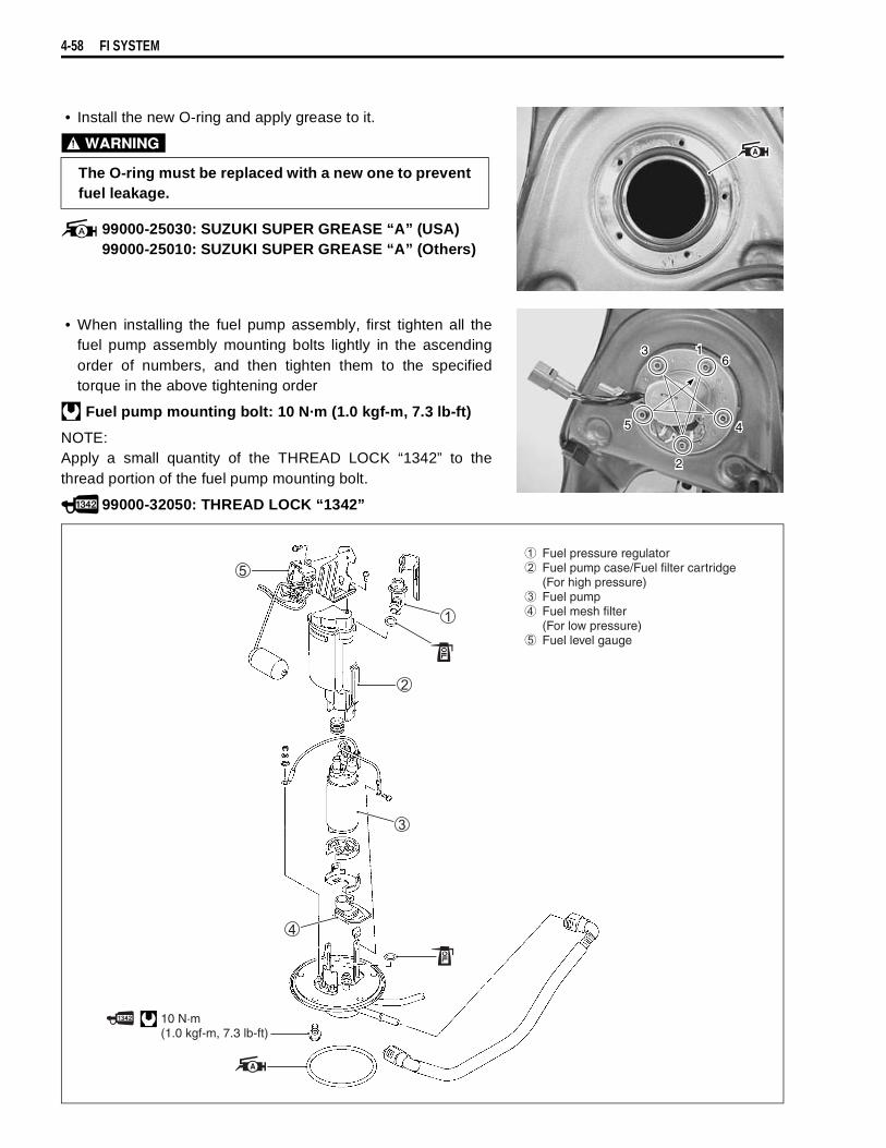
4-58 FI SYSTEM
• Install the new O-ring and apply grease to it.
99000-25030: SUZUKI SUPER GREASE “A” (USA)99000-25010: SUZUKI SUPER GREASE “A” (Others)
• When installing the fuel pump assembly, first tighten all thefuel pump assembly mounting bolts lightly in the ascendingorder of numbers, and then tighten them to the specifiedtorque in the above tightening order
.
Fuel pump mounting bolt: 10 N·m (1.0 kgf-m, 7.3 lb-ft)
NOTE:Apply a small quantity of the THREAD LOCK “1342” to thethread portion of the fuel pump mounting bolt.
99000-32050: THREAD LOCK “1342”
The O-ring must be replaced with a new one to preventfuel leakage.
1
2
3
45
6
10 N·m(1.0 kgf-m, 7.3 lb-ft)
Fuel pressure regulator Fuel pump case/Fuel filter cartridge
(For high pressure) Fuel pump Fuel mesh filter
(For low pressure) Fuel level gauge
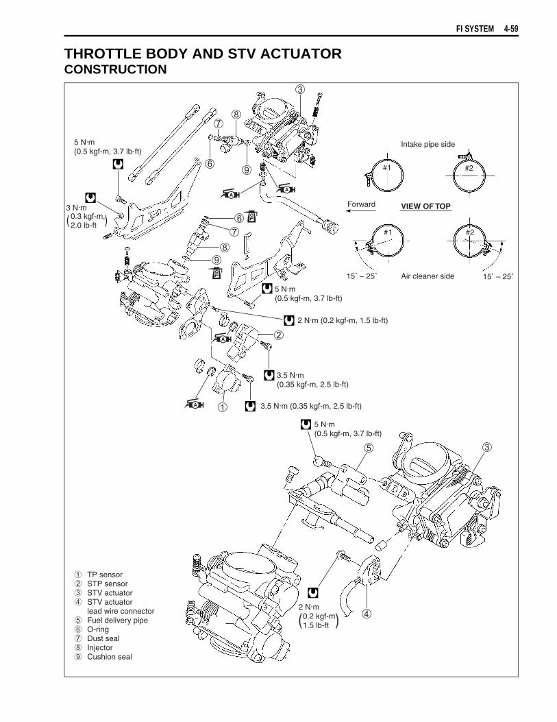
FI SYSTEM 4-59
THROTTLE BODY AND STV ACTUATORCONSTRUCTION
5 N.m(0.5 kgf-m, 3.7 lb-ft)
3 N.m0.3 kgf-m,2.0 lb-ft( )
2 N.m (0.2 kgf-m, 1.5 lb-ft)
5 N.m(0.5 kgf-m, 3.7 lb-ft)
3.5 N.m(0.35 kgf-m, 2.5 lb-ft)
2 N.m 0.2 kgf-m 1.5 lb-ft( )
5 N.m(0.5 kgf-m, 3.7 lb-ft)
TP sensor STP sensor STV actuator STV actuator
lead wire connector Fuel delivery pipe O-ring Dust seal Injector Cushion seal
3.5 N.m (0.35 kgf-m, 2.5 lb-ft)
VIEW OF TOP
Intake pipe side
Air cleaner side15˚ – 25˚ 15˚ – 25˚
#1
#1
#2
#2
Forward

4-60 FI SYSTEM
THROTTLE BODY REMOVAL• Remove the fuel tank. ( 4-52)• Loosen the respective throttle body clamp screws (air cleaner
side).• Disconnect the *PAIR solenoid valve lead wire coupler, IAP
senor coupler and IAT sensor coupler.• Disconnect the PAIR hoses from the PAIR solenoid valve.• Remove the air cleaner box.
* For E-24 model is operated by the vacuum.
• Loosen the respective throttle body clamp screws (intake pipeside).
• Disconnect the various lead wire couplers.
STP sensor
TP sensor/Fuel injector
STVA motor

FI SYSTEM 4-61
• Disconnect the throttle cables from their drum.• Dismount the throttle body assembly.
THROTTLE BODY DISASSEMBLY• Remove the IAP sensor vacuum damper and its hose.
• Remove the throttle link rod
and secondary throttle link rod
.
NOTE:The throttle link rod
is longer than the secondary throttle linkrod
.
• Remove the fuel delivery pipe.
* Be careful not to damage the throttle cable bracketand fast idle lever when dismounting or remountingthe throttle body assembly.
* After disconnecting the throttle cables, do not snapthe throttle valve from full open to full close. It maycause damage to the throttle valve and throttle body.
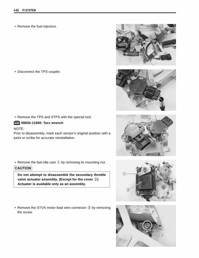
4-62 FI SYSTEM
• Remove the fuel injectors.
• Disconnect the TPS coupler.
• Remove the TPS and STPS with the special tool.
09930-11950: Torx wrench
NOTE:Prior to disassembly, mark each sensor’s original position with apaint or scribe for accurate reinstallation.
• Remove the fast idle cam
by removing its mounting nut.
• Remove the STVA motor lead wire connector
by removingthe screw.
Do not attempt to disassemble the secondary throttlevalve actuator assembly. (Except for the cover
)Actuator is available only as an assembly.

FI SYSTEM 4-63
Never remove the STVA motor yoke and motor.
Avoid removing the STV adjuster
unless absolutely necessary.
Never remove the throttle valve and secondary throttlevalve.
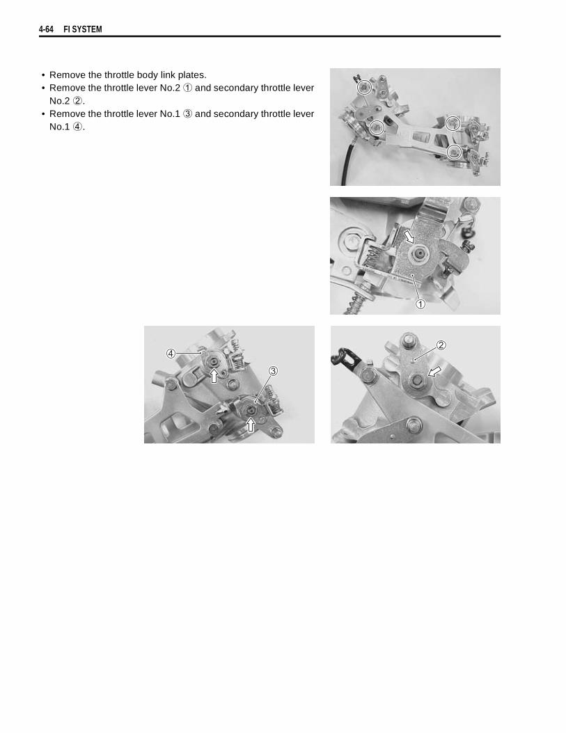
4-64 FI SYSTEM
• Remove the throttle body link plates.• Remove the throttle lever No.2
and secondary throttle leverNo.2
.• Remove the throttle lever No.1
and secondary throttle leverNo.1
.
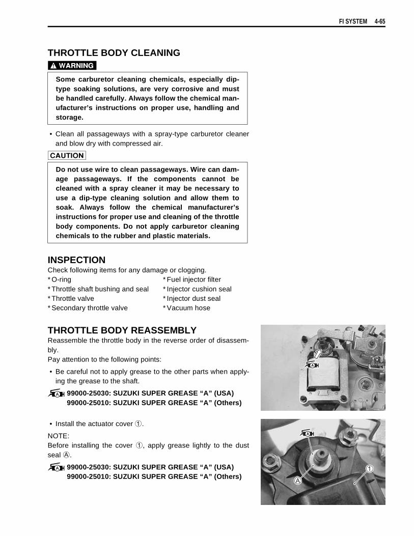
FI SYSTEM 4-65
THROTTLE BODY CLEANING
• Clean all passageways with a spray-type carburetor cleanerand blow dry with compressed air.
INSPECTIONCheck following items for any damage or clogging.* O-ring * Fuel injector filter* Throttle shaft bushing and seal * Injector cushion seal* Throttle valve * Injector dust seal* Secondary throttle valve * Vacuum hose
THROTTLE BODY REASSEMBLYReassemble the throttle body in the reverse order of disassem-bly.Pay attention to the following points:
• Be careful not to apply grease to the other parts when apply-ing the grease to the shaft.
99000-25030: SUZUKI SUPER GREASE “A” (USA)99000-25010: SUZUKI SUPER GREASE “A” (Others)
• Install the actuator cover
.
NOTE:Before installing the cover
, apply grease lightly to the dustseal
.
99000-25030: SUZUKI SUPER GREASE “A” (USA)99000-25010: SUZUKI SUPER GREASE “A” (Others)
Some carburetor cleaning chemicals, especially dip-type soaking solutions, are very corrosive and mustbe handled carefully. Always follow the chemical man-ufacturer’s instructions on proper use, handling andstorage.
Do not use wire to clean passageways. Wire can dam-age passageways. If the components cannot becleaned with a spray cleaner it may be necessary touse a dip-type cleaning solution and allow them tosoak. Always follow the chemical manufacturer’sinstructions for proper use and cleaning of the throttlebody components. Do not apply carburetor cleaningchemicals to the rubber and plastic materials.
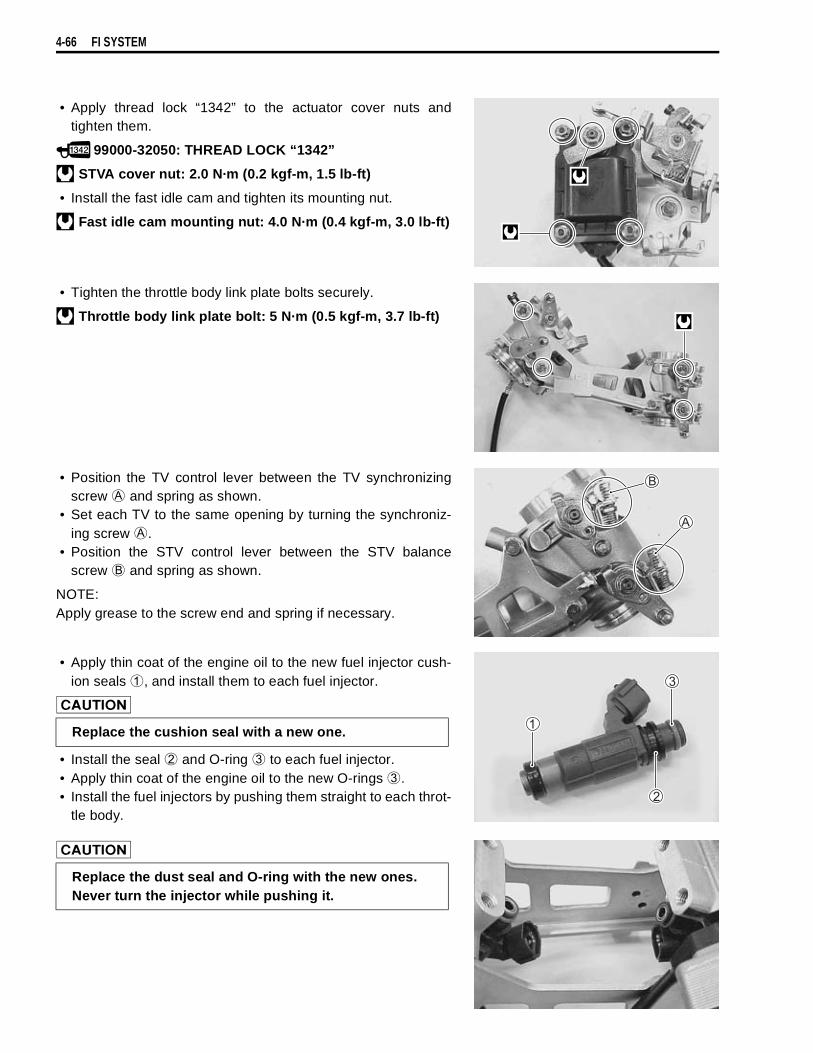
4-66 FI SYSTEM
• Apply thread lock “1342” to the actuator cover nuts andtighten them.
99000-32050: THREAD LOCK “1342”
STVA cover nut: 2.0 N·m (0.2 kgf-m, 1.5 lb-ft)
• Install the fast idle cam and tighten its mounting nut.
Fast idle cam mounting nut: 4.0 N·m (0.4 kgf-m, 3.0 lb-ft)
• Tighten the throttle body link plate bolts securely.
Throttle body link plate bolt: 5 N·m (0.5 kgf-m, 3.7 lb-ft)
• Position the TV control lever between the TV synchronizingscrew
and spring as shown.• Set each TV to the same opening by turning the synchroniz-
ing screw
.• Position the STV control lever between the STV balance
screw
and spring as shown.
NOTE:Apply grease to the screw end and spring if necessary.
• Apply thin coat of the engine oil to the new fuel injector cush-ion seals
, and install them to each fuel injector.
• Install the seal
and O-ring
to each fuel injector.• Apply thin coat of the engine oil to the new O-rings
.• Install the fuel injectors by pushing them straight to each throt-
tle body.
Replace the cushion seal with a new one.
Replace the dust seal and O-ring with the new ones.Never turn the injector while pushing it.

FI SYSTEM 4-67
• Connect the fuel injector couplers to the fuel injectors.
NOTE:The fuel injector coupler No.1 (FRONT) can be distinguishedfrom that of the No.2 (REAR) by the “F” mark.
• Install the fuel delivery pipe assembly to the throttle bodyassembly.
• Tighten the fuel delivery pipe mounting screws.
Fuel delivery pipe mounting screw:5 N·m (0.5 kgf-m, 3.7 lb-ft)
• Install the throttle link rod
and secondary throttle link rod
.
NOTE:The throttle link rod
is longer than the secondary throttle linkrod
.
• Apply a small quantity of grease to the shaft ends and seallips.
99000-25030: SUZUKI SUPER GREASE “A” (USA)99000-25010: SUZUKI SUPER GREASE “A” (Others)
• With the STV fully closed, install the STP sensor.
09930-11950: Torx wrench
STP sensor mounting screw: 3.5 N·m (0.35 kgf-m, 2.5 lb-ft)
NOTE:STP sensor and TP sensor reassemble each other very closelyin external appearance.Make sure to check the terminal numbers of coupler.STP sensor: 4-pin TPS sensor: 3-pin
Never turn the fuel injectors while installing them.

4-68 FI SYSTEM
• With the TV fully closed, install the TP sensor.
09930-11950: Torx wrench
TP sensor mounting screw: 3.5 N·m (0.35 kgf-m, 2.5 lb-ft)
• Set each STV to the same opening by turning the balancescrew
.
STP SENSOR ADJUSTMENTIf the STP sensor adjustment is necessary, measure the sensorresistance and adjust the STP sensor positioning as follows:• Disconnect the STP sensor coupler.• Set the ST valve to fully close position by finger and measure
the resistance T3 and T4 terminals.
STP sensor setting resistanceST valve is fully closed: Approx. 1.1 kΩ
(
T3 –
T4)
09900-25008: Multi circuit tester
Tester knob indication: Resistance (Ω)
• Loosen the STP sensor mounting screws.• Adjust the STP sensor until resistance is within specification
and tighten the STP sensor mounting screws.
09930-11950: Torx wrench
STP sensor mounting screw:3.5 N·m (0.35 kgf-m, 2.5 lb-ft)
Ω
T3
T4
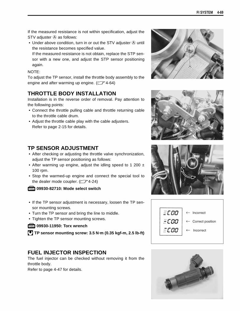
FI SYSTEM 4-69
If the measured resistance is not within specification, adjust theSTV adjuster
as follows:• Under above condition, turn in or out the STV adjuster
untilthe resistance becomes specified value.If the measured resistance is not obtain, replace the STP sen-sor with a new one, and adjust the STP sensor positioningagain.
NOTE:To adjust the TP sensor, install the throttle body assembly to theengine and after warming up engine. ( 4-64)
THROTTLE BODY INSTALLATIONInstallation is in the reverse order of removal. Pay attention tothe following points:• Connect the throttle pulling cable and throttle returning cable
to the throttle cable drum.• Adjust the throttle cable play with the cable adjusters.
Refer to page 2-15 for details.
TP SENSOR ADJUSTMENT• After checking or adjusting the throttle valve synchronization,
adjust the TP sensor positioning as follows:• After warming up engine, adjust the idling speed to 1 200 ±
100 rpm.• Stop the warmed-up engine and connect the special tool to
the dealer mode coupler. ( 4-24)
09930-82710: Mode select switch
• If the TP sensor adjustment is necessary, loosen the TP sen-sor mounting screws.
• Turn the TP sensor and bring the line to middle.• Tighten the TP sensor mounting screws.
09930-11950: Torx wrench
TP sensor mounting screw: 3.5 N·m (0.35 kgf-m, 2.5 lb-ft)
FUEL INJECTOR INSPECTIONThe fuel injector can be checked without removing it from thethrottle body.Refer to page 4-47 for details.
Incorrect
Correct position
Incorrect

4-70 FI SYSTEM
FUEL INJECTOR REMOVAL• Remove the fuel tank and air cleaner box. ( 4-52 and -60)• Remove the fuel delivery pipe assembly. ( 4-61)• Disconnect the injector couplers.• Remove the fuel injectors No.1 and No.2. ( 4-62)
INSPECTIONCheck fuel injector filter for evidence of dirt and contamination. Ifpresent, clean and check for presence of dirt in the fuel lines andfuel tank.
FUEL INJECTOR INSTALLATION• Apply thin coat of the engine oil to new injector cushion seals
and O-rings.• Install the injector by pushing it straight to the throttle body.
Never turn the injector while pushing it. ( 4-67)
FAST IDLE INSPECTIONThe fast idle system is automatic type.When the fast idle cam is turned by the secondary throttle valveactuator, the cam pushes the lever on the throttle valve shaftcausing the throttle valve to open and raise the engine speed.When the engine has warmed up, depending on the water tem-perature and ambient temperature as shown in the followingtable, the fast idle is cancelled allowing the engine to resumeidle speed.
If, under the above conditions, the fast idle cannot be cancelled,the cause may possibly be short-circuit in engine coolant tem-perature sensor or wiring connections or maladjusted fast idle.
STV actuator
Fast idle cam
Throttlevalve lever
The throttle valvelever opens throttlevalve a little to increasethe engine speed.
Ambient Temp. Fast idle rpmFast idle cancelling Water Temp.
– 5 °C(– 23 °F)
1 800 – 2 400 rpm50 – 60 °C
(122 – 140 °F)
15 °C(59 °F)
1 700 – 2 300 rpm45 – 55 °C
(113 – 131 °F)
25 °C(77 °F)
1 500 – 2 100 rpm45 – 55 °C
(113 – 131 °F)
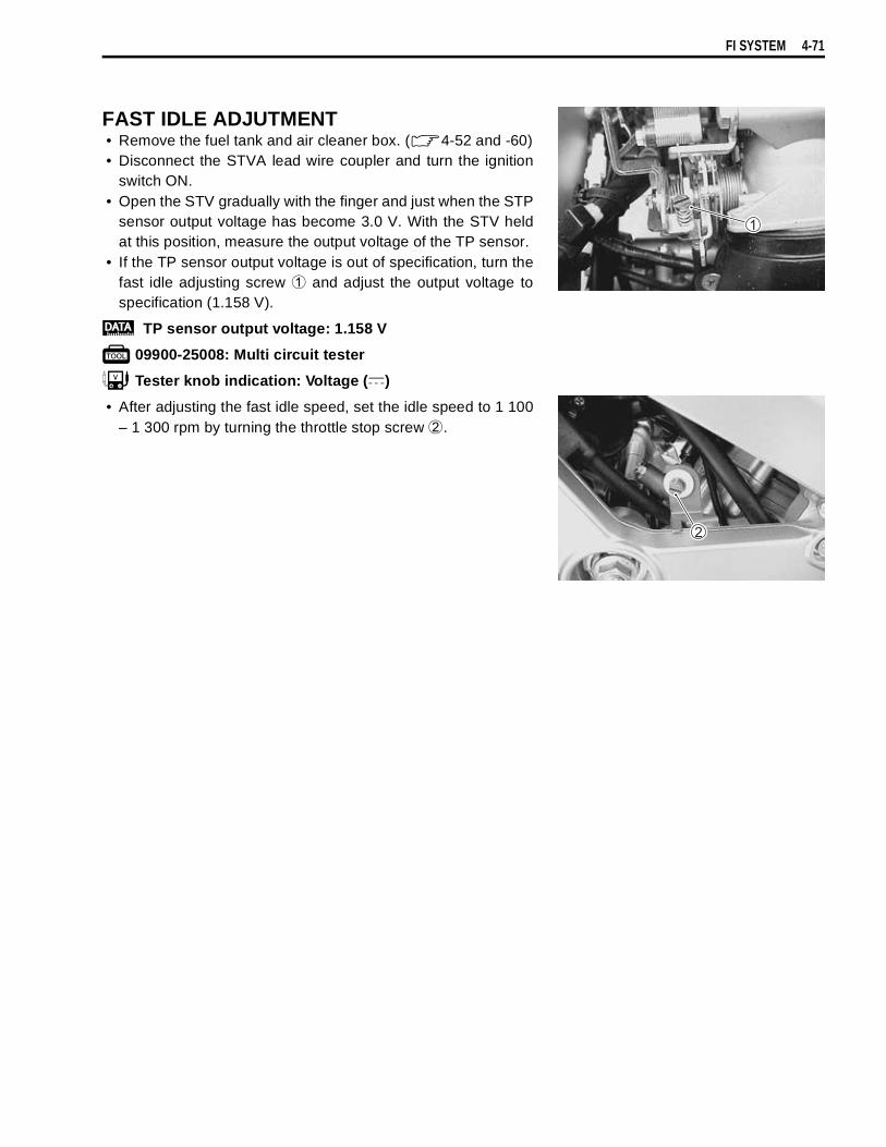
FI SYSTEM 4-71
FAST IDLE ADJUTMENT• Remove the fuel tank and air cleaner box. ( 4-52 and -60)• Disconnect the STVA lead wire coupler and turn the ignition
switch ON.• Open the STV gradually with the finger and just when the STP
sensor output voltage has become 3.0 V. With the STV heldat this position, measure the output voltage of the TP sensor.
• If the TP sensor output voltage is out of specification, turn thefast idle adjusting screw
and adjust the output voltage tospecification (1.158 V).
TP sensor output voltage: 1.158 V
09900-25008: Multi circuit tester
Tester knob indication: Voltage ( )
• After adjusting the fast idle speed, set the idle speed to 1 100– 1 300 rpm by turning the throttle stop screw
.

4-72 FI SYSTEM
THROTTLE VALVE SYNCHRONIZATIONCheck and adjust the throttle valve synchronization between twocylinders.
09913-13121: Vacuum balancer gauge
NOTE:Before balancing the throttle valves, calibrate each vacuum bal-ancer gauge.
• Remove the fuel tank and air cleaner box. ( 4-52 and -60)• Remove the rubber caps
from the vacuum nipples on therespective throttle bodies and connect the vacuum balancergauge hoses to each vacuum nipple.
• Connect the removed IAT sensor
and IAP sensor
.
• Connect the fuel tank and fuel delivery pipe with the fuel feedhose (special tool).
09940-40220: Fuel pressure gauge hose attachment
• Connect the fuel pump lead wire coupler.
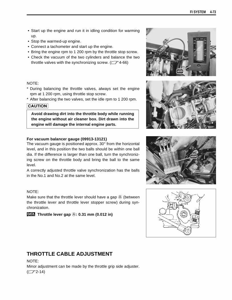
FI SYSTEM 4-73
• Start up the engine and run it in idling condition for warmingup.
• Stop the warmed-up engine.• Connect a tachometer and start up the engine.• Bring the engine rpm to 1 200 rpm by the throttle stop screw.• Check the vacuum of the two cylinders and balance the two
throttle valves with the synchronizing screw. ( 4-66)
NOTE:* During balancing the throttle valves, always set the engine
rpm at 1 200 rpm, using throttle stop screw.* After balancing the two valves, set the idle rpm to 1 200 rpm.
For vacuum balancer gauge (09913-13121)The vacuum gauge is positioned approx. 30° from the horizontallevel, and in this position the two balls should be within one balldia. If the difference is larger than one ball, turn the synchroniz-ing screw on the throttle body and bring the ball to the samelevel.A correctly adjusted throttle valve synchronization has the ballsin the No.1 and No.2 at the same level.
NOTE:Make sure that the throttle lever should have a gap
(betweenthe throttle lever and throttle lever stopper screw) during syn-chronization.
Throttle lever gap
: 0.31 mm (0.012 in)
THROTTLE CABLE ADJUSTMENTNOTE:Minor adjustment can be made by the throttle grip side adjuster.( 2-14)
Avoid drawing dirt into the throttle body while runningthe engine without air cleaner box. Dirt drawn into theengine will damage the internal engine parts.
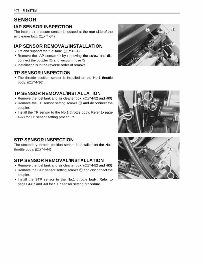
4-74 FI SYSTEM
SENSORIAP SENSOR INSPECTIONThe intake air pressure sensor is located at the rear side of theair cleaner box. ( 4-34)
IAP SENSOR REMOVAL/INSTALLATION• Lift and support the fuel tank. ( 4-51)• Remove the IAP sensor
by removing the screw and dis-connect the coupler
and vacuum hose
.• Installation is in the reverse order of removal.
TP SENSOR INSPECTION• The throttle position sensor is installed on the No.1 throttle
body. ( 4-36)
TP SENSOR REMOVAL/INSTALLATION• Remove the fuel tank and air cleaner box. ( 4-52 and -60)• Remove the TP sensor setting screws
and disconnect thecoupler.
• Install the TP sensor to the No.1 throttle body. Refer to page4-68 for TP sensor setting procedure.
STP SENSOR INSPECTIONThe secondary throttle position sensor is installed on the No.1throttle body. ( 4-44)
STP SENSOR REMOVAL/INSTALLATION• Remove the fuel tank and air cleaner box. ( 4-52 and -60)• Remove the STP sensor setting screws
and disconnect thecoupler.
• Install the STP sensor to the No.1 throttle body. Refer topages 4-67 and -68 for STP sensor setting procedure.
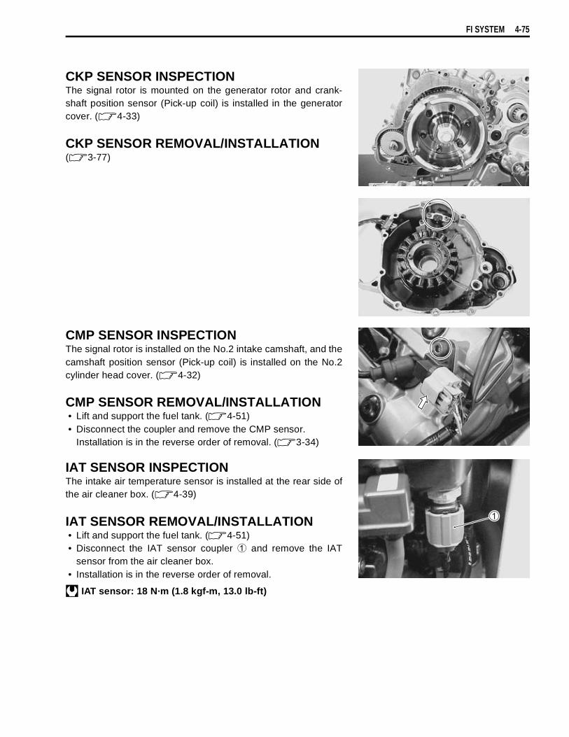
FI SYSTEM 4-75
CKP SENSOR INSPECTIONThe signal rotor is mounted on the generator rotor and crank-shaft position sensor (Pick-up coil) is installed in the generatorcover. ( 4-33)
CKP SENSOR REMOVAL/INSTALLATION( 3-77)
CMP SENSOR INSPECTIONThe signal rotor is installed on the No.2 intake camshaft, and thecamshaft position sensor (Pick-up coil) is installed on the No.2cylinder head cover. ( 4-32)
CMP SENSOR REMOVAL/INSTALLATION• Lift and support the fuel tank. ( 4-51)• Disconnect the coupler and remove the CMP sensor.
Installation is in the reverse order of removal. ( 3-34)
IAT SENSOR INSPECTIONThe intake air temperature sensor is installed at the rear side ofthe air cleaner box. ( 4-39)
IAT SENSOR REMOVAL/INSTALLATION• Lift and support the fuel tank. ( 4-51)• Disconnect the IAT sensor coupler
and remove the IATsensor from the air cleaner box.
• Installation is in the reverse order of removal.
IAT sensor: 18 N·m (1.8 kgf-m, 13.0 lb-ft)
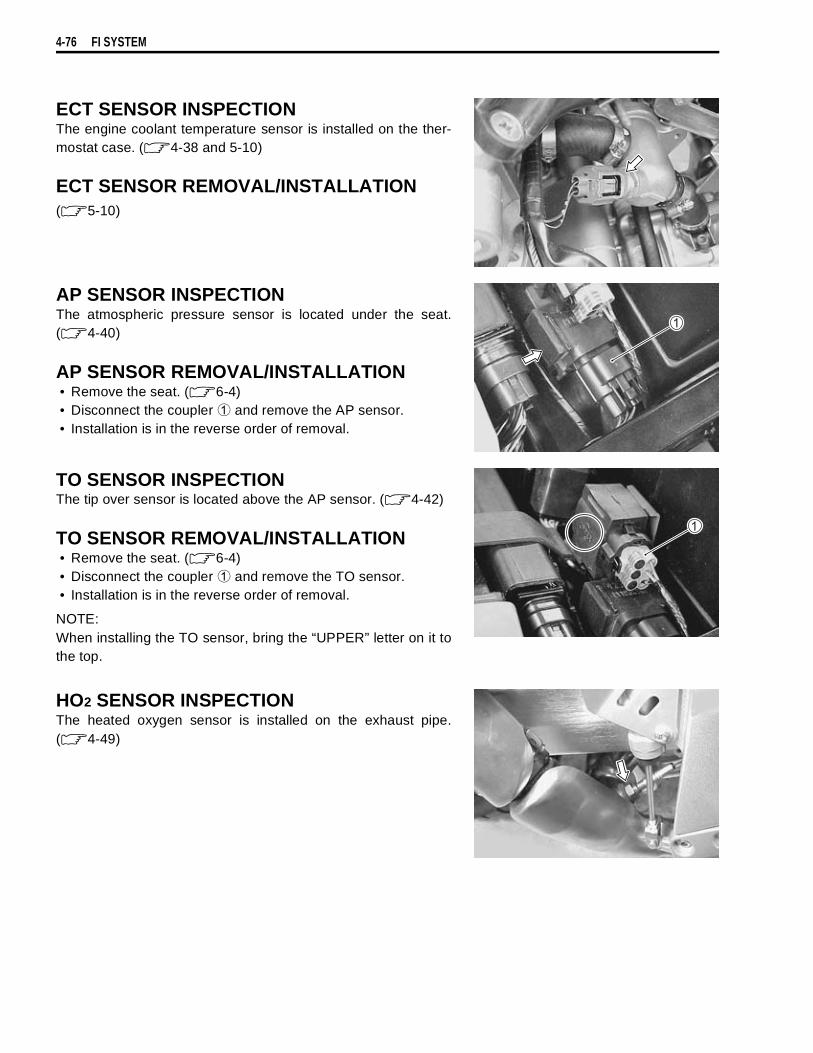
4-76 FI SYSTEM
ECT SENSOR INSPECTIONThe engine coolant temperature sensor is installed on the ther-mostat case. ( 4-38 and 5-10)
ECT SENSOR REMOVAL/INSTALLATION( 5-10)
AP SENSOR INSPECTIONThe atmospheric pressure sensor is located under the seat.( 4-40)
AP SENSOR REMOVAL/INSTALLATION• Remove the seat. ( 6-4)• Disconnect the coupler
and remove the AP sensor.• Installation is in the reverse order of removal.
TO SENSOR INSPECTIONThe tip over sensor is located above the AP sensor. ( 4-42)
TO SENSOR REMOVAL/INSTALLATION• Remove the seat. ( 6-4)• Disconnect the coupler
and remove the TO sensor.• Installation is in the reverse order of removal.
NOTE:When installing the TO sensor, bring the “UPPER” letter on it tothe top.
HO2 SENSOR INSPECTIONThe heated oxygen sensor is installed on the exhaust pipe.( 4-49)

FI SYSTEM 4-77
HO2 SENSOR REMOVAL/INSTALLATION• Remove the engine under cover.• Disconnect the HO2 sensor lead wire couplers.• Remove the HO2 sensor unit.
• Installation is in the reverse order of removal.
• Tighten the sensor unit to the specified torque.
HO2 SENSOR: 47.5 N·m (4.75 kgf-m, 34.3 lb-ft)
• Route the HO2 sensor lead wire into the frame. ( 8-16)• Connect the HO2 sensor couplers.
Do not remove the HO2 sensor while it is hot.
Be careful not to expose it to excessive shock.Do not use an impact wrench while removing orinstalling the HO2 sensor unit.Be careful not to twist or damage the sensor lead wire.
Do not apply oil or other materials to the sensor airhole.

5
COOLING AND LUBRICATION SYSTEM 5-1
CONTENTS
COOLING AND LUBRICATION SYSTEM
ENGINE COOLANT ..............................................................................5- 2COOLING CIRCUIT ..............................................................................5- 3
COOLING CIRCUIT INSPECTION ..............................................5- 3RADIATOR ...........................................................................................5- 4
REMOVAL ....................................................................................5- 4INSPECTION AND CLEANING ...................................................5- 5INSTALLATION ...........................................................................5- 6
RADIATOR RESERVOIR TANK ..........................................................5- 6REMOVAL/INSTALLATION ........................................................5- 6
RADIATOR CAP ...................................................................................5- 6INSPECTION ................................................................................5- 6
WATER HOSE ......................................................................................5- 7INSPECTION ................................................................................5- 7
COOLING FAN .....................................................................................5- 8REMOVAL ....................................................................................5- 8INSPECTION ................................................................................5- 8INSTALLATION ...........................................................................5- 8
COOLING FAN THERMO-SWITCH .....................................................5- 9REMOVAL ....................................................................................5- 9INSPECTION ................................................................................5- 9INSTALLATION ...........................................................................5- 9
ENGINE COOLANT TEMPERATURE SENSOR .................................5-10REMOVAL ....................................................................................5-10INSPECTION ................................................................................5-10INSTALATION ..............................................................................5-10
THERMOSTAT .....................................................................................5-11REMOVAL ....................................................................................5-11INSPECTION ................................................................................5-11INSTALLATION ...........................................................................5-12
WATER PUMP ......................................................................................5-13REMOVAL AND DISASSEMBLY ................................................5-13INSPECTION ................................................................................5-15REASSEMBLY AND INSTALLATION .........................................5-15
LUBRICATION SYSTEM ......................................................................5-18OIL PRESSURE ...........................................................................5-18OIL FILTER ..................................................................................5-18OIL PRESSURE REGULATOR ...................................................5-18OIL STRAINER ............................................................................5-18OIL JET ........................................................................................5-18OIL PUMP ....................................................................................5-18OIL PRESSURE SWITCH ............................................................5-18
OIL COOLER ........................................................................................5-18REMOVAL ....................................................................................5-18INSPECTION AND CLEANING ...................................................5-19INSTALLATION ...........................................................................5-19
ENGINE LUBRICATION FLOW CHART .............................................5-20ENGINE LUBRICATION CIRCUIT .......................................................5-21
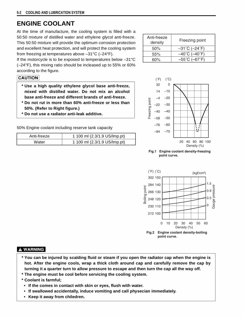
5-2 COOLING AND LUBRICATION SYSTEM
ENGINE COOLANTAt the time of manufacture, the cooling system is filled with a50:50 mixture of distilled water and ethylene glycol anti-freeze.This 50:50 mixture will provide the optimum corrosion protectionand excellent heat protection, and will protect the cooling systemfrom freezing at temperatures above –31°C (–24°F).If the motorcycle is to be exposed to temperatures below –31°C(–24°F), this mixing ratio should be incleased up to 55% or 60%according to the figure.
50% Engine coolant including reserve tank capacity
* Use a high quality ethylene glycol base anti-freeze,mixed with distilled water. Do not mix an alcoholbase anti-freeze and different brands of anti-freeze.
* Do not rut in more than 60% anti-freeze or less than50%. (Refer to Right figure.)
* Do not use a radiator anti-leak additive.
Anti-freeze 1 100 ml (2.3/1.9 US/lmp.pt)Water 1 100 ml (2.3/1.9 US/lmp.pt)
Anti-freezedensity Freezing point
50%55%60%
–31˚C (–24˚F)–40˚C (–40˚F)–55˚C (–67˚F)
20 40 60 80 100Density (%)
0
–10
–20
–30
–40
–50
–60
–70
32
14
–4
–22
–40
–58
–76
–94
Free
zing
poi
ntFig.1 Engine coolant density-freezing point curve.
(˚C)(˚F)
0 10 20 30 40 50 60Density (%)
150
140
130
120
110
100
Boi
ling
poin
t
(˚C)(˚F)
302
284
266
248
230
212
Engine coolant density-boilingpoint curve.
Fig.2
(kgf/cm²)
1.5
0.9
0.5
0
Gau
ge p
ress
ure
* You can be injured by scalding fluid or steam if you open the radiator cap when the engine ishot. After the engine cools, wrap a thick cloth around cap and carefully remove the cap byturning it a quarter turn to allow pressure to escape and then turn the cap all the way off.
* The engine must be cool before servicing the cooling system.* Coolant is farmful;
• If the comes in contact with skin or eyes, flush with water.• If swallowed accidentally, induce vomiting and call physecian immediately.• Keep it away from chiledren.

COOLING AND LUBRICATION SYSTEM 5-3
COOLING CIRCUIT
COOLING CIRCUIT INSPECTIONBefore removing the radiator and draining the engine coolant,inspect the cooling circuit for tightness.• Remove the cowling. ( 6-6)• Remove the radiator cap
and connect the tester
to thefiller.
• Give a pressure of about 110 kPa (1.1 kgf/cm², 15.6 psi) andsee if the system holds this pressure for 10 seconds.
• If the pressure should fall during fhis 10-second interval, itmeans that there is a leaking point in the system. In such acase, inspect the entire system and replace the leaking com-ponent or part.
Do not remove the radiator cap when the engine ishot.
When removing the radiator cap tester, put a rag onthe filler to prevent spouting of engine coolant.
Do not allow the pressure to exceed the radiator caprelease pressure, or the radiator can be damaged.
THERMOSTAT
RESERVE TANK
RADIATOR (Upper)
NO. 1 CYLINDER HEAD
NO. 1 CYLINDER
NO. 2 CYLINDER
NO. 2 CYLINDER HEAD
RADIATOR (Lower)
WATER PUMP
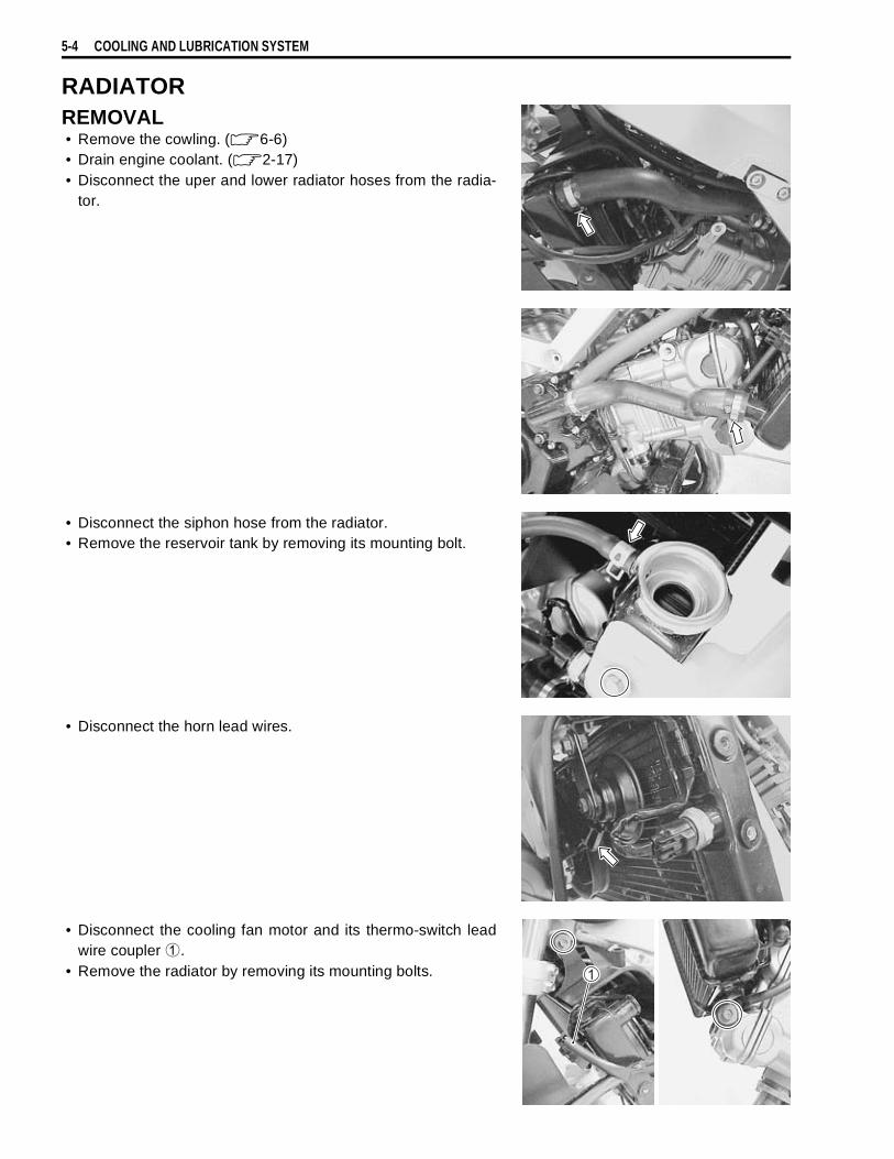
5-4 COOLING AND LUBRICATION SYSTEM
RADIATORREMOVAL• Remove the cowling. ( 6-6)• Drain engine coolant. ( 2-17)• Disconnect the uper and lower radiator hoses from the radia-
tor.
• Disconnect the siphon hose from the radiator.• Remove the reservoir tank by removing its mounting bolt.
• Disconnect the horn lead wires.
• Disconnect the cooling fan motor and its thermo-switch leadwire coupler
.• Remove the radiator by removing its mounting bolts.

COOLING AND LUBRICATION SYSTEM 5-5
• With the fasteners unlocked, remove the radiator shroud
.
• Remove the cooling fan and horn.• Remove the cooling fan thermo-switch.
INSPECTION AND CLEANING• Road dirt or trash stuck to the fins must be removed.• Use of compressed air is recommended for this cleaning.
• Fins bent down or dented can be repaired by straighteningthem with the blade of a small screwdriver.
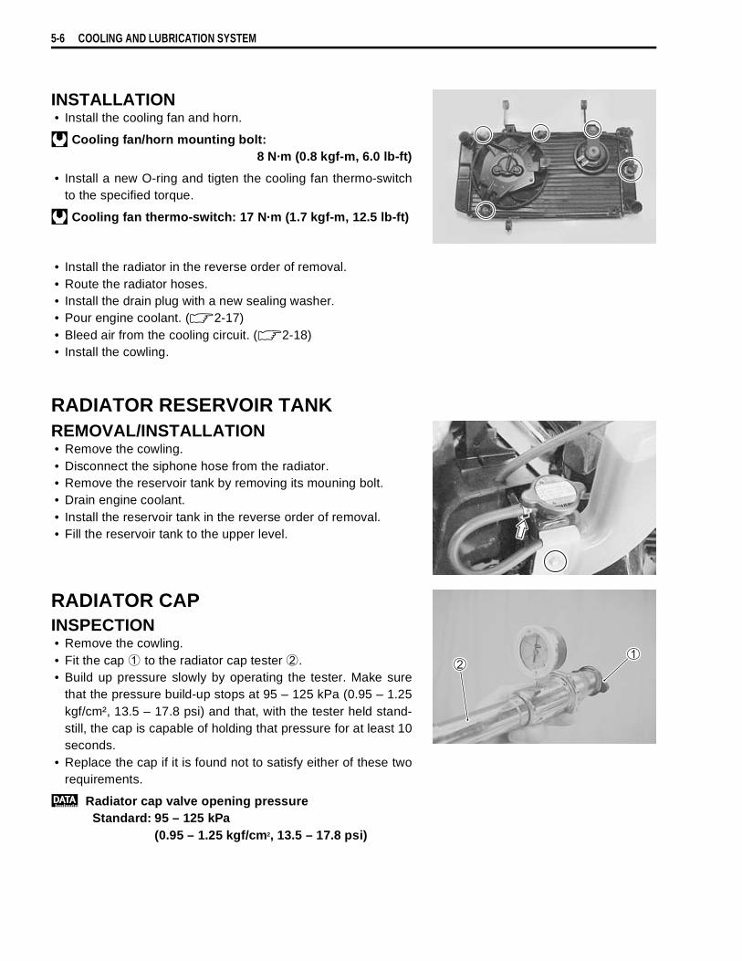
5-6 COOLING AND LUBRICATION SYSTEM
INSTALLATION• Install the cooling fan and horn.
Cooling fan/horn mounting bolt:8 N·m (0.8 kgf-m, 6.0 lb-ft)
• Install a new O-ring and tigten the cooling fan thermo-switchto the specified torque.
Cooling fan thermo-switch: 17 N·m (1.7 kgf-m, 12.5 lb-ft)
• Install the radiator in the reverse order of removal.• Route the radiator hoses.• Install the drain plug with a new sealing washer.• Pour engine coolant. ( 2-17)• Bleed air from the cooling circuit. ( 2-18)• Install the cowling.
RADIATOR RESERVOIR TANKREMOVAL/INSTALLATION• Remove the cowling.• Disconnect the siphone hose from the radiator.• Remove the reservoir tank by removing its mouning bolt.• Drain engine coolant.• Install the reservoir tank in the reverse order of removal.• Fill the reservoir tank to the upper level.
RADIATOR CAPINSPECTION• Remove the cowling.• Fit the cap
to the radiator cap tester
.• Build up pressure slowly by operating the tester. Make sure
that the pressure build-up stops at 95 – 125 kPa (0.95 – 1.25kgf/cm², 13.5 – 17.8 psi) and that, with the tester held stand-still, the cap is capable of holding that pressure for at least 10seconds.
• Replace the cap if it is found not to satisfy either of these tworequirements.
Radiator cap valve opening pressureStandard: 95 – 125 kPa
(0.95 – 1.25 kgf/cm2, 13.5 – 17.8 psi)
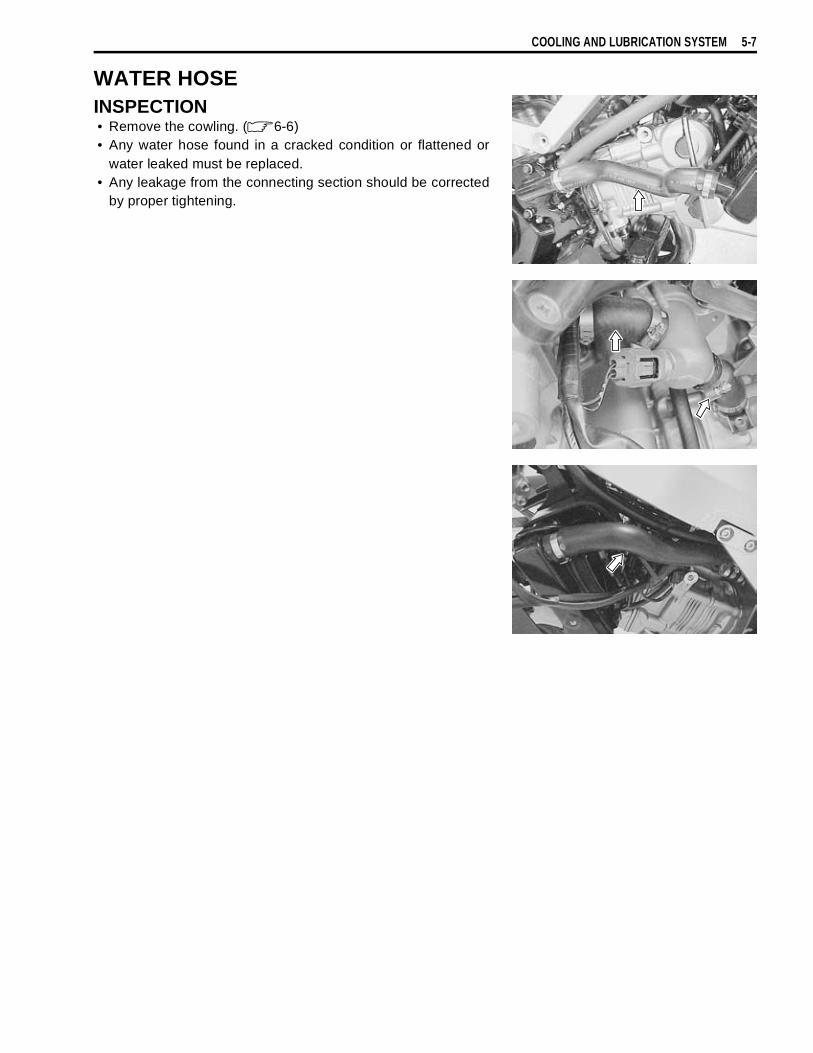
COOLING AND LUBRICATION SYSTEM 5-7
WATER HOSEINSPECTION• Remove the cowling. ( 6-6)• Any water hose found in a cracked condition or flattened or
water leaked must be replaced.• Any leakage from the connecting section should be corrected
by proper tightening.

5-8 COOLING AND LUBRICATION SYSTEM
COOLING FANREMOVAL• Remove the cowling. ( 6-6)• Drain engine coolant. ( 2-17)• Remove the radiator. ( 5-4)• Remove the cooling fan.
INSPECTION• Remove the cowling. ( 6-6)• Disconnect the cooling fan motor lead wire coupler
.• Test the cooling fan motor for load current with an ammeter
connected as shown in the illustration.
• The voltmeter is for making sure that the battery applies 12volts to the motor. With the motor with electric motor fan run-ning at full speed, the ammeter should be indicating not morethan 5 amperes.
• If the fan motor does not turn, replace the motor assemblywith a new one.
NOTE:When making above test, it is not necessary to remove the cool-ing fan.
INSTALLATION• Install the cooling fan.
Cooling fan motor mounting bolt:8 N·m (0.8 kgf-m, 6.0 lb-ft)
• Install the radiator.• Route the radiator hoses. ( 8-23)• Pour engine coolant. ( 2-17)• Bleed the air from the cooling circuit. ( 2-18)• Install the cowling. ( 6-6)
Fan motor Ammeter
Battery
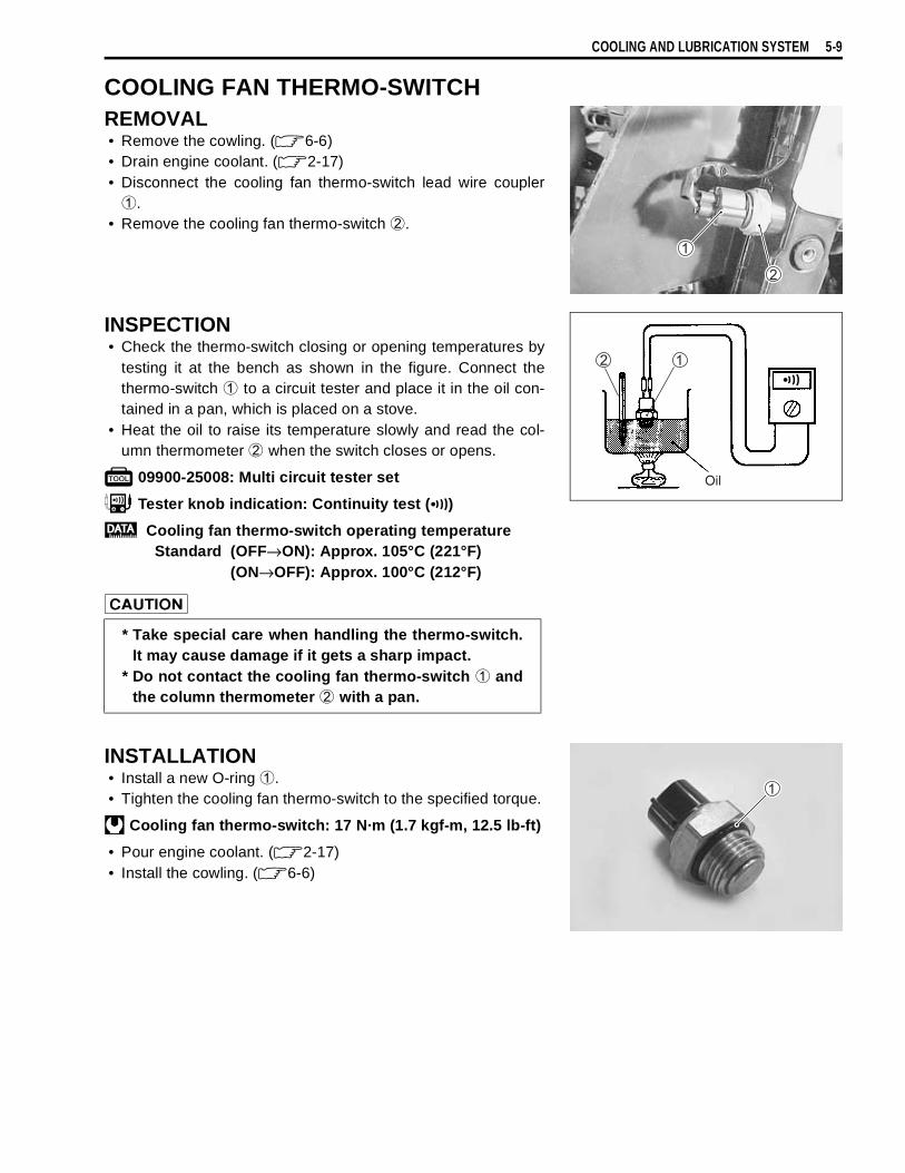
COOLING AND LUBRICATION SYSTEM 5-9
COOLING FAN THERMO-SWITCHREMOVAL• Remove the cowling. ( 6-6)• Drain engine coolant. ( 2-17)• Disconnect the cooling fan thermo-switch lead wire coupler
.• Remove the cooling fan thermo-switch
.
INSPECTION• Check the thermo-switch closing or opening temperatures by
testing it at the bench as shown in the figure. Connect thethermo-switch
to a circuit tester and place it in the oil con-tained in a pan, which is placed on a stove.
• Heat the oil to raise its temperature slowly and read the col-umn thermometer
when the switch closes or opens.
09900-25008: Multi circuit tester set
Tester knob indication: Continuity test ( )
Cooling fan thermo-switch operating temperatureStandard (OFF→ON): Approx. 105°C (221°F)
(ON→OFF): Approx. 100°C (212°F)
INSTALLATION• Install a new O-ring
.• Tighten the cooling fan thermo-switch to the specified torque.
Cooling fan thermo-switch: 17 N·m (1.7 kgf-m, 12.5 lb-ft)
• Pour engine coolant. ( 2-17)• Install the cowling. ( 6-6)
Oil
* Take special care when handling the thermo-switch.It may cause damage if it gets a sharp impact.
* Do not contact the cooling fan thermo-switch
andthe column thermometer
with a pan.

5-10 COOLING AND LUBRICATION SYSTEM
ENGINE COOLANT TEMPERATURE SENSORREMOVAL• Drain engine coolant. ( 2-17)• Remove the seat. ( 6-4)• Remove the fuel tank right side cover.• Remove the IAP sensor vacuum damper.• Disconnect the engine coolant temperature sensor lead wire
coupler.• Place a rag under the sensor and remove the engine coolant
temperature sensor
.
INSPECTION• Check the engine coolant temperature by testing it at the
bench as shown in the figure. Connect the temperature sen-sor
to a circuit tester and place it in the water contained in apan, which is placed on a stove.
• Heat the water to raise its temperature slowly and read thecolumn thermometer
and the ohmmeter.• If the temperature sensor ohmic valve does not change in the
proportion indicated, replace it with a new one.Temperature sensor specification
If the resistance noted to show infinty or too much different resis-tance value, replace the temperature sensor with a new one.
INSTALATION• Install a new sealing washer
.• Tighten the engine coolant temperature sensor to the speci-
fied torque.Engine coolant temperature sensor:
18 N·m (1.8 kgf-m, 13.0 lb-ft)
• Pour engine coolant. ( 2-17)• Install the fuel tank right side cover. ( 6-4)• Install the seat.
Temperature Standard resistance20°C (68°F) Approx. 2.45 kΩ
40°C (104°F) Approx. 1.148 kΩ60°C (140°F) Approx. 0.587 kΩ80°C (176°F) Approx. 0.322 kΩ
* Take special care when handling the temperaturesensor. It may cause damage if it gets a sharpimpact.
* Do not contact the engine coolant temperature sen-sor
and the column thermometer
with a pan.
Take special care when handling the temperature sen-sor. It may cause damage if it gets a sharp impact.
Water
Ω

COOLING AND LUBRICATION SYSTEM 5-11
THERMOSTATREMOVAL• Drain engine coolant. ( 2-17)• Place a rag under the thermostat case.• Remove the thermostat case.
• Remove the thermostat
.
INSPECTIONInspect the thermostat pellet for signs of cracking.Test the thermostat at the bench for control action, in the follow-ing manner.• Pass a string between flange, as shown in the photograph.• Immerse the thermostat in the water contained in a beaker, as
shown in the illustration. Note that the immersed thermostat isin suspension. Heat the water by placing the beaker on astove and observe the rising temperature on a thermometer.
• Read the thermometer just when opening the thermostat. Thisreading, which is the temperature level at which the thermo-stat valve begins to open, should be within the standardvalue.
Thermostat valve opening temperatureStandard: Approx. 88 °C (190 °F)
• Keep on heating the water to raise its temperature.• Just when the water temperature reaches specified value, the
thermostat valve should have lifted by at least 8.0 mm(0.31 in).
Thermostat valve liftStandard: Over 8.0 mm at 100 °C (Over 0.31 in at 212 °F)
• A thermostat failing to satisfy either of the two requirements(start-to-open temperature and valve lift) must be replaced.
Stove Thermometer
Water
Valve lift

5-12 COOLING AND LUBRICATION SYSTEM
INSTALLATION• Install the thermostat.
NOTE:The jiggle valve
of the thermostat faces upside.
• Install the thermostat case.• Tighten the thermostat case bolts to the specified torque.
Thermostat case bolt: 10 N·m (1.0 kgf-m, 7.0 lb-ft)
• Pour engine coolant. ( 2-17)
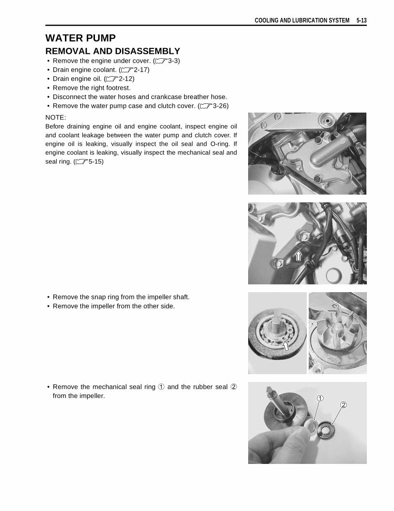
COOLING AND LUBRICATION SYSTEM 5-13
WATER PUMPREMOVAL AND DISASSEMBLY• Remove the engine under cover. ( 3-3)• Drain engine coolant. ( 2-17)• Drain engine oil. ( 2-12)• Remove the right footrest.• Disconnect the water hoses and crankcase breather hose.• Remove the water pump case and clutch cover. ( 3-26)
NOTE:Before draining engine oil and engine coolant, inspect engine oiland coolant leakage between the water pump and clutch cover. Ifengine oil is leaking, visually inspect the oil seal and O-ring. Ifengine coolant is leaking, visually inspect the mechanical seal andseal ring. ( 5-15)
• Remove the snap ring from the impeller shaft.• Remove the impeller from the other side.
• Remove the mechanical seal ring
and the rubber seal
from the impeller.
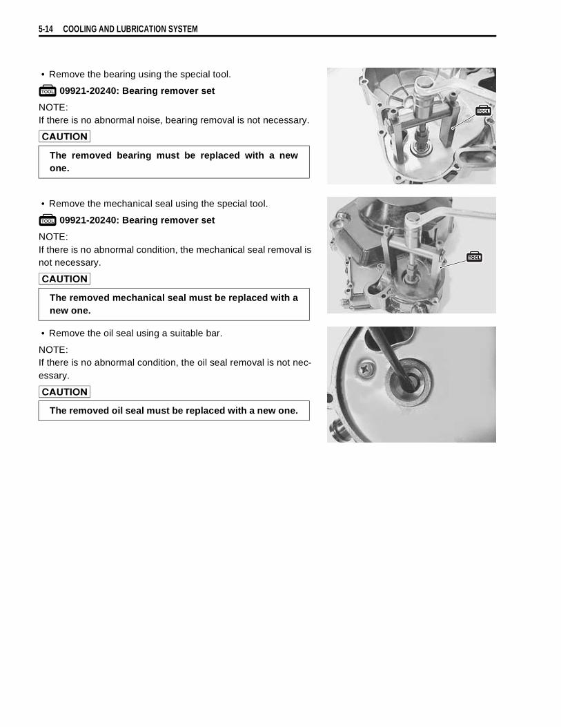
5-14 COOLING AND LUBRICATION SYSTEM
• Remove the bearing using the special tool.
09921-20240: Bearing remover set
NOTE:If there is no abnormal noise, bearing removal is not necessary.
• Remove the mechanical seal using the special tool.
09921-20240: Bearing remover set
NOTE:If there is no abnormal condition, the mechanical seal removal isnot necessary.
• Remove the oil seal using a suitable bar.
NOTE:If there is no abnormal condition, the oil seal removal is not nec-essary.
The removed bearing must be replaced with a newone.
The removed mechanical seal must be replaced with anew one.
The removed oil seal must be replaced with a new one.
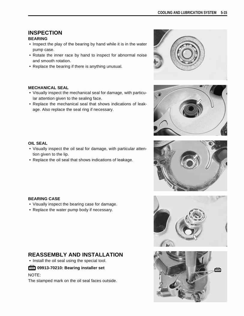
COOLING AND LUBRICATION SYSTEM 5-15
INSPECTIONBEARING• Inspect the play of the bearing by hand while it is in the water
pump case.• Rotate the inner race by hand to inspect for abnormal noise
and smooth rotation.• Replace the bearing if there is anything unusual.
MECHANICAL SEAL• Visually inspect the mechanical seal for damage, with particu-
lar attention given to the sealing face.• Replace the mechanical seal that shows indications of leak-
age. Also replace the seal ring if necessary.
OIL SEAL• Visually inspect the oil seal for damage, with particular atten-
tion given to the lip.• Replace the oil seal that shows indications of leakage.
BEARING CASE• Visually inspect the bearing case for damage.• Replace the water pump body if necessary.
REASSEMBLY AND INSTALLATION• Install the oil seal using the special tool.
09913-70210: Bearing installer set
NOTE:The stamped mark on the oil seal faces outside.
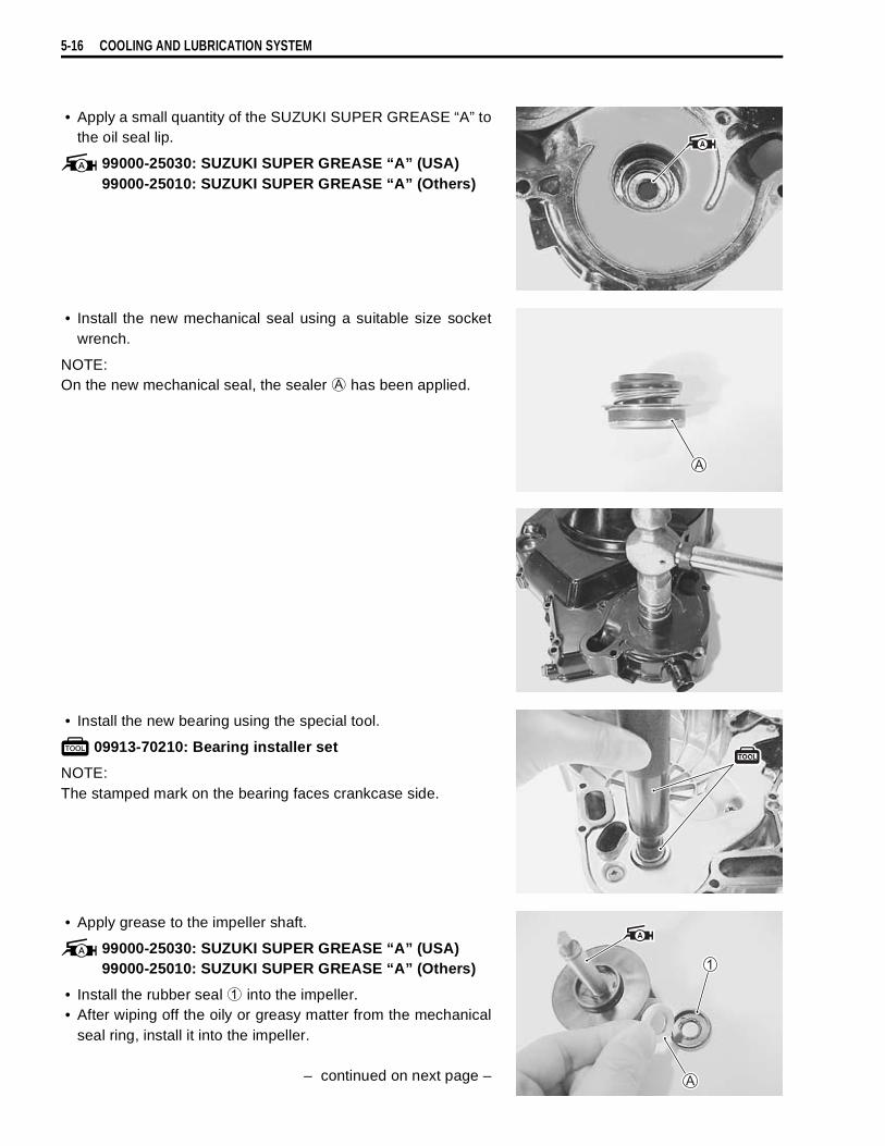
5-16 COOLING AND LUBRICATION SYSTEM
• Apply a small quantity of the SUZUKI SUPER GREASE “A” tothe oil seal lip.
99000-25030: SUZUKI SUPER GREASE “A” (USA)99000-25010: SUZUKI SUPER GREASE “A” (Others)
• Install the new mechanical seal using a suitable size socketwrench.
NOTE:On the new mechanical seal, the sealer
has been applied.
• Install the new bearing using the special tool.
09913-70210: Bearing installer set
NOTE:The stamped mark on the bearing faces crankcase side.
• Apply grease to the impeller shaft.
99000-25030: SUZUKI SUPER GREASE “A” (USA)99000-25010: SUZUKI SUPER GREASE “A” (Others)
• Install the rubber seal
into the impeller.• After wiping off the oily or greasy matter from the mechanical
seal ring, install it into the impeller.
– continued on next page –
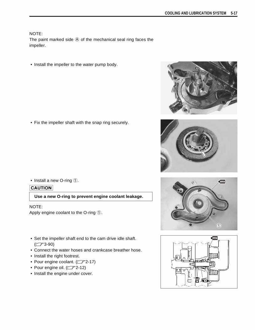
COOLING AND LUBRICATION SYSTEM 5-17
NOTE:The paint marked side
of the mechanical seal ring faces theimpeller.
• Install the impeller to the water pump body.
• Fix the impeller shaft with the snap ring securely.
• Install a new O-ring
.
NOTE:Apply engine coolant to the O-ring
.
• Set the impeller shaft end to the cam drive idle shaft.( 3-90)
• Connect the water hoses and crankcase breather hose.• Install the right footrest.• Pour engine coolant. ( 2-17)• Pour engine oil. ( 2-12)• Install the engine under cover.
Use a new O-ring to prevent engine coolant leakage.
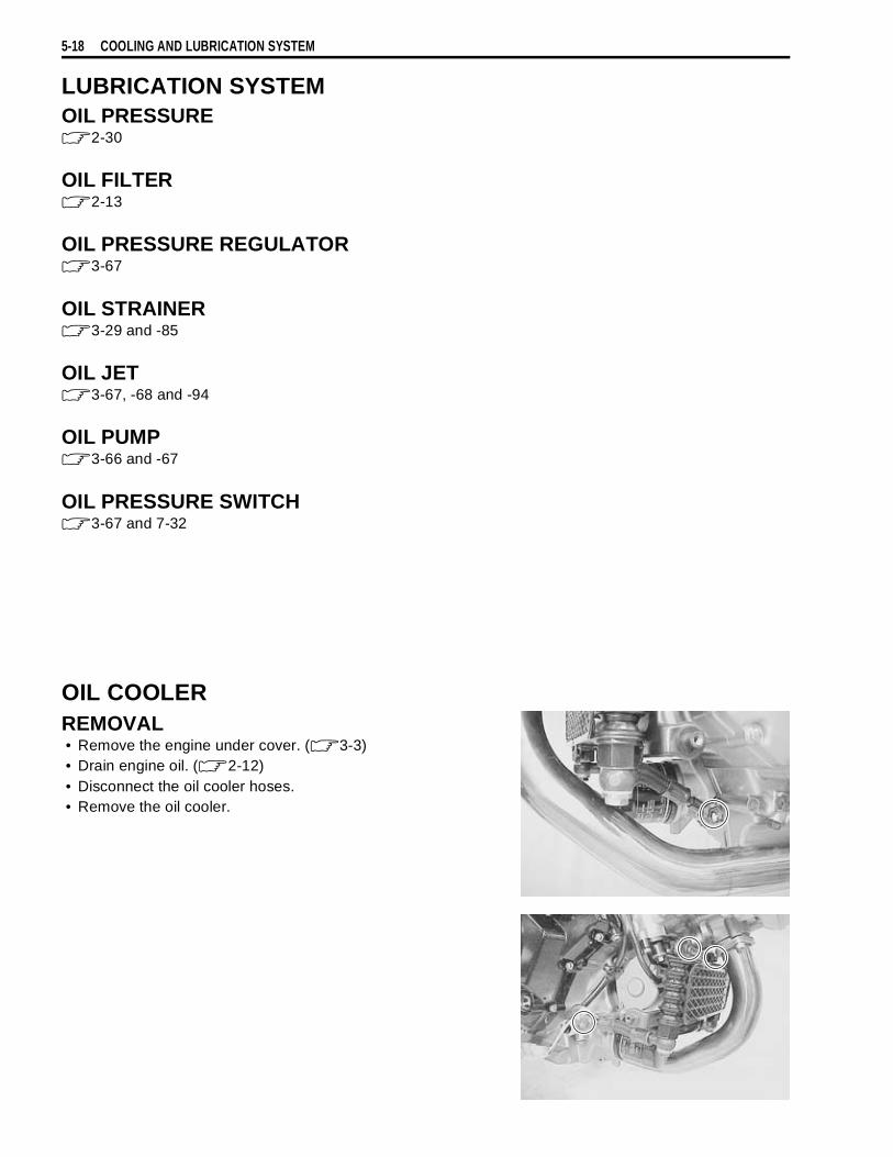
5-18 COOLING AND LUBRICATION SYSTEM
LUBRICATION SYSTEMOIL PRESSURE
2-30
OIL FILTER2-13
OIL PRESSURE REGULATOR3-67
OIL STRAINER3-29 and -85
OIL JET3-67, -68 and -94
OIL PUMP3-66 and -67
OIL PRESSURE SWITCH3-67 and 7-32
OIL COOLERREMOVAL• Remove the engine under cover. ( 3-3)• Drain engine oil. ( 2-12)• Disconnect the oil cooler hoses.• Remove the oil cooler.

COOLING AND LUBRICATION SYSTEM 5-19
• Remove the oil cooler fin guard net.• Remove the oil hoses.
INSPECTION AND CLEANING• Inspect the oil cooler and hose joints for oil leakage. If any
defect are found, replace the oil cooler and oil hoses with thenew ones.
• Road dirt or trash stuck to the fins must be removed.• Use of compressed air is recommended for this cleaning.
• Fins bent down or dented can be repaired by straighteningthem with the blade of a small screwdriver.
INSTALLATION• Install a new gasket washer
.
• Install the oil cooler.
Oil cooler mounting bolt: 10 N·m (1.0 kgf-m, 7.3 lb-ft)
• Tighten the oil cooler hose union bolts to the specified torque.
Oil cooler hose union bolt: 23 N·m (2.3 kgf-m, 16.5 lb-ft)
Use a new gasket washer to prevent engine oil leak-age.

5-20 COOLING AND LUBRICATION SYSTEM
ENGINE LUBRICATION FLOW CHART
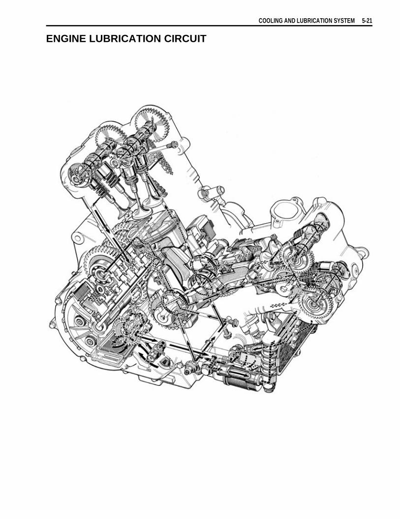
COOLING AND LUBRICATION SYSTEM 5-21
ENGINE LUBRICATION CIRCUIT


6
CHASSIS 6-1
CHASSIS
CONTENTSEXTERIOR PARTS ......................................................................................................................................6- 2
CONSTRUCTION ............................................................................................................................6- 2REMOVAL .......................................................................................................................................6- 4
FRONT WHEEL ...........................................................................................................................................6- 8CONSTRUCTION ............................................................................................................................6- 8REMOVAL .......................................................................................................................................6- 9INSPECTION AND DISASSEMBLY ...............................................................................................6- 9REASSEMBLY AND REMOUNTING .............................................................................................6-11
FRONT FORK ..............................................................................................................................................6-14CONSTRUCTION ............................................................................................................................6-14REMOVAL AND DISASSEMBLY ...................................................................................................6-15INSPECTION ...................................................................................................................................6-18REASSEMBLY AND REMOUNTING .............................................................................................6-19
STEERING AND HANDLEBAR ..................................................................................................................6-24CONSTRUCTION ............................................................................................................................6-24REMOVAL .......................................................................................................................................6-25INSPECTION AND DISASSEMBLY ...............................................................................................6-28REASSEMBLY AND REMOUNTING .............................................................................................6-29STEERING TENSION ADJUSTMENT ............................................................................................6-32
REAR WHEEL .............................................................................................................................................6-33CONSTRUCTION ............................................................................................................................6-33REMOVAL .......................................................................................................................................6-34INSPECTION AND DISASSEMBLY ...............................................................................................6-35REASSEMBLY AND REMOUNTING .............................................................................................6-38
REAR SHOCK ABSORBER .......................................................................................................................6-42CONSTRUCTION ............................................................................................................................6-42REMOVAL .......................................................................................................................................6-43INSPECTION ...................................................................................................................................6-44REAR SHOCK ABSORBER DISPOSAL ........................................................................................6-44REMOUNTING ................................................................................................................................6-45SUSPENSION SETTING .................................................................................................................6-46
REAR SWINGARM ......................................................................................................................................6-47CONSTRUCTION ............................................................................................................................6-47REMOVAL .......................................................................................................................................6-48INSPECTION AND DISASSEMBLY ...............................................................................................6-49REASSEMBLY ................................................................................................................................6-52REMOUNTING ................................................................................................................................6-54FINAL INSPECTION AND ADJUSTMENT .....................................................................................6-55
FRONT BRAKE ...........................................................................................................................................6-56CONSTRUCTION ............................................................................................................................6-56BRAKE PAD REPLACEMENT .......................................................................................................6-57BRAKE FLUID REPLACEMENT ....................................................................................................6-58CALIPER REMOVAL AND DISASSEMBLY ..................................................................................6-59CALIPER INSPECTION ..................................................................................................................6-60CALIPER REASSEMBLY AND REMOUNTING .............................................................................6-61BRAKE DISC INSPECTION ...........................................................................................................6-62MASTER CYLINDER REMOVAL AND DISASSEMBLY ...............................................................6-63MASTER CYLINDER INSPECTION ...............................................................................................6-64MASTER CYLINDER REASSEMBLY AND REMOUNTING ..........................................................6-64
REAR BRAKE .............................................................................................................................................6-66CONSTRUCTION ............................................................................................................................6-66BRAKE PAD REPLACEMENT .......................................................................................................6-67BRAKE FLUID REPLACEMENT ....................................................................................................6-68CALIPER REMOVAL AND DISASSEMBLY ..................................................................................6-69CALIPER INSPECTION ..................................................................................................................6-70BRAKE DISC INSPECTION ...........................................................................................................6-71CALIPER REASSEMBLY AND REMOUNTING .............................................................................6-72MASTER CYLINDER REMOVAL AND DISASSEMBLY ...............................................................6-73MASTER CYLINDER INSPECTION ...............................................................................................6-74MASTER CYLINDER REASSEMBLY AND REMOUNTING ..........................................................6-75
CLUTCH RELEASE CYLINDER AND MASTER CYLINDER .....................................................................6-77CONSTRUCTION ............................................................................................................................6-77CLUTCH FLUID REPLACEMENT ..................................................................................................6-78CLUTCH RELEASE CYLINDER REMOVAL AND DISASSEMBLY ..............................................6-78CLUTCH RELEASE CYLINDER INSPECTION ..............................................................................6-79CLUTCH RELEASE CYLINDER REASSEMBLY AND REMOUNTING ........................................6-79CLUTCH MASTER CYLINDER REMOVAL AND DISASSEMBLY ................................................6-81CLUTCH MASTER CYLINDER INSPECTION ...............................................................................6-82CLUTCH MASTER CYLINDER REASSEMBLY AND REMOUNTING ..........................................6-82
TIRE AND WHEEL ......................................................................................................................................6-84TIRE REMOVAL ..............................................................................................................................6-84INSPECTION ...................................................................................................................................6-84VALVE INSTALLATION .................................................................................................................6-85TIRE INSTALLATION .....................................................................................................................6-85
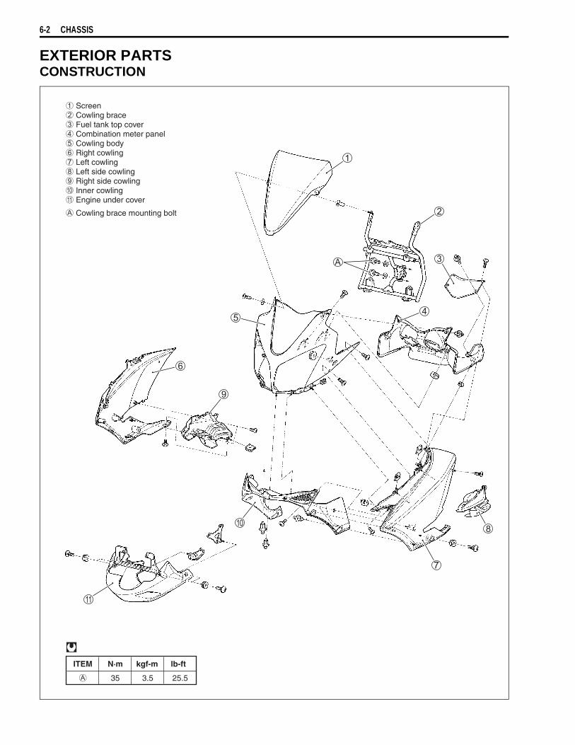
6-2 CHASSIS
EXTERIOR PARTSCONSTRUCTION
ITEM N·m kgf-m lb-ft
35 3.5 25.5
Screen Cowling brace Fuel tank top cover Combination meter panel Cowling body Right cowling Left cowling Left side cowling Right side cowling Inner cowling Engine under cover
Cowling brace mounting bolt

CHASSIS 6-3
S
eat r
ail
R
ear
fend
er N
o. 1
R
ear
fend
er N
o. 2
F
ram
e co
ver
ITE
MN
·mkg
f-m
lb-f
t
50
5.0
36.0
S
eat r
ail m
ount
ing
bolt

6-4 CHASSIS
REMOVALSEAT• Remove the seat with the ignition key.
FRONT TANK COVERS• Remove the seat. ( Above)• Remove the fuel tank side cover mounting secrew.• Remove thefuel tank side cover by pulling on the hooked
parts.
: hooked part
CARRIER• Remove the seat. ( Above)• Remove the carrier.
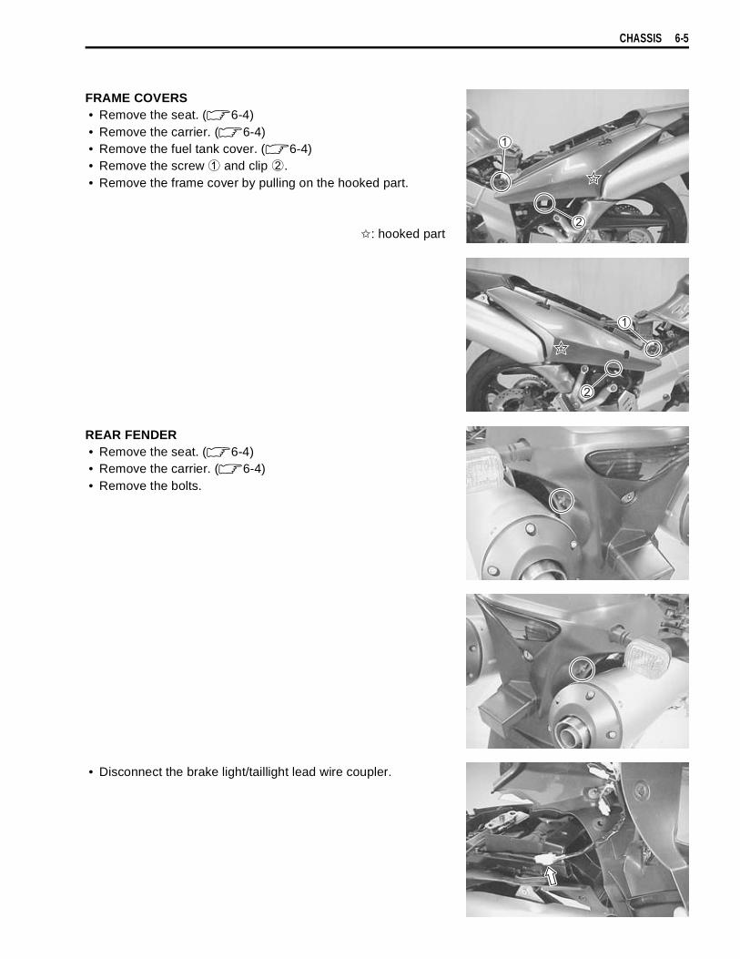
CHASSIS 6-5
FRAME COVERS• Remove the seat. ( 6-4)• Remove the carrier. ( 6-4)• Remove the fuel tank cover. ( 6-4)• Remove the screw
and clip
.• Remove the frame cover by pulling on the hooked part.
: hooked part
REAR FENDER• Remove the seat. ( 6-4)• Remove the carrier. ( 6-4)• Remove the bolts.
• Disconnect the brake light/taillight lead wire coupler.
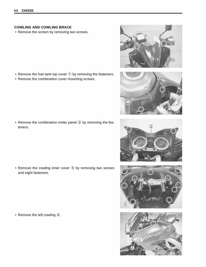
6-6 CHASSIS
COWLING AND COWLING BRACE• Remove the screen by removing two screws.
• Remove the fuel tank top cover
by removing the fasteners.• Remove the combination cover mounting screws.
• Remove the combination meter panel
by removing the fas-teners.
• Remove the cowling inner cover
by removing two screwsand eight fasteners.
• Remove the left cowling
.

CHASSIS 6-7
• Remove the right cowling
.
• Remove the turn signals.• Remove the cowling body
.
• Disconnect the couplers.
• Remove the cowling blace
.• Remove the combination meter. ( 7-22)
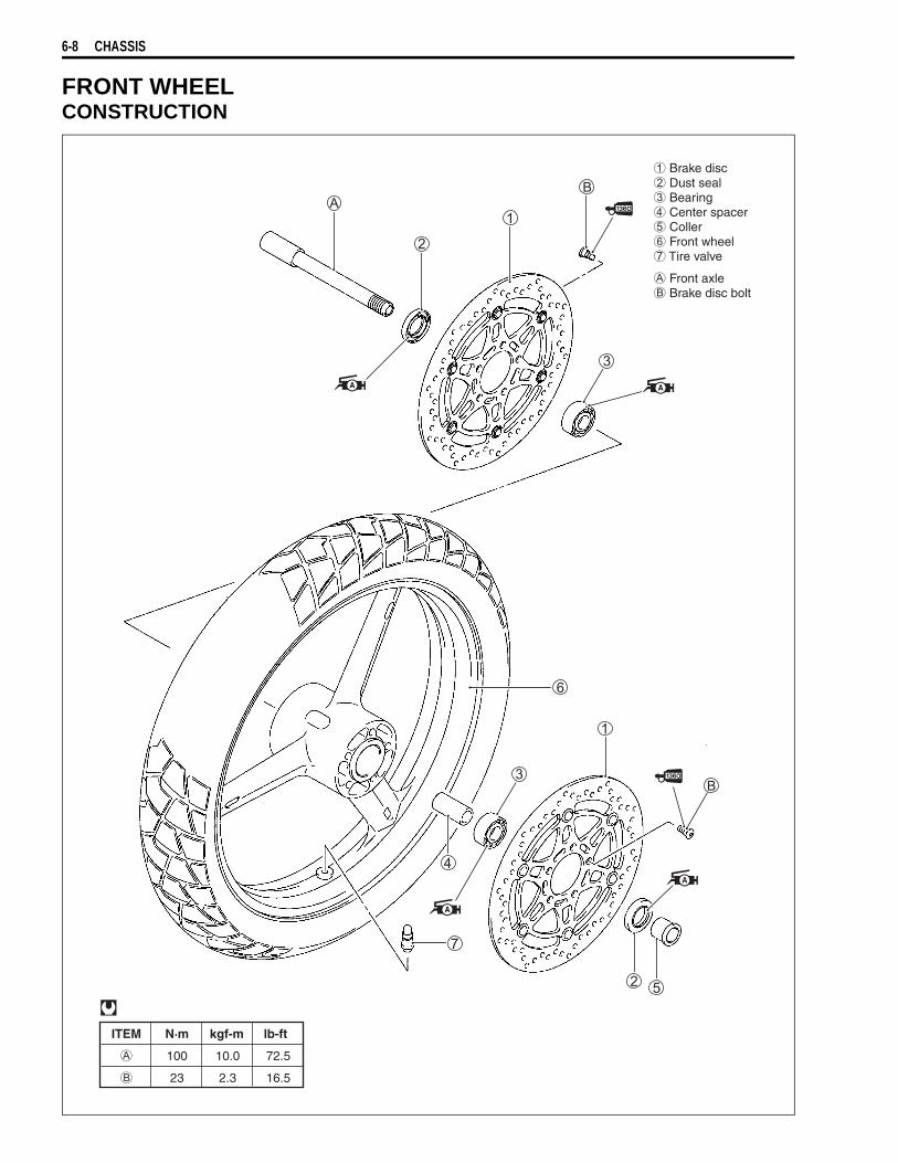
6-8 CHASSIS
FRONT WHEELCONSTRUCTION
ITEM N·m kgf-m lb-ft
100 10.0 72.5
23 2.3 16.5
Brake disc Dust seal Bearing Center spacer Coller Front wheel Tire valve
Front axle Brake disc bolt

CHASSIS 6-9
REMOVAL• Remove the right and left brake calipers
.• Loosen two axle pinch bolts
on the right front fork leg.
• Slightly loosen the front axle by using the special tool.
09944-28320: Hexagon bit 19 mm
• Raise the front wheel off the ground and support the motorcy-cle with a jack or a wooden block.
• Remove the front axle and the front wheel.• Remove the spacer
.
NOTE:After removing the front wheel, fit the calipers temporarily to theoriginal positions.
INSPECTION AND DISASSEMBLYTIRE ( 6-84)BRAKE DISC ( 6-62)
• Remove the brake discs.
DUST SEAL• Inspect the dust seals lip for wear or damage. If any damages
are found, replace the dust seals with new ones.
Do not operate the brake lever while removing the cal-ipers.
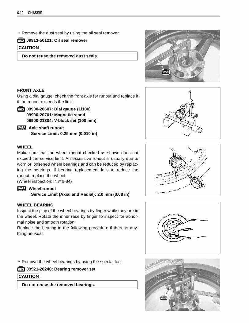
6-10 CHASSIS
• Remove the dust seal by using the oil seal remover.
09913-50121: Oil seal remover!
FRONT AXLEUsing a dial gauge, check the front axle for runout and replace itif the runout exceeds the limit.
09900-20607: Dial gauge (1/100)09900-20701: Magnetic stand09900-21304: V-block set (100 mm)
Axle shaft runoutService Limit: 0.25 mm (0.010 in)
WHEELMake sure that the wheel runout checked as shown does notexceed the service limit. An excessive runout is usually due toworn or loosened wheel bearings and can be reduced by replac-ing the bearings. If bearing replacement fails to reduce therunout, replace the wheel.(Wheel inspection: 6-84)
Wheel runoutService Limit (Axial and Radial): 2.0 mm (0.08 in)
WHEEL BEARINGInspect the play of the wheel bearings by finger while they are inthe wheel. Rotate the inner race by finger to inspect for abnor-mal noise and smooth rotation.Replace the bearing in the following procedure if there is any-thing unusual.
• Remove the wheel bearings by using the special tool.
09921-20240: Bearing remover set
Do not reuse the removed dust seals.
Do not reuse the removed bearings.

CHASSIS 6-11
REASSEMBLY AND REMOUNTINGReassemble and remount the front wheel in the reverse order of removal and disassembly. Pay attention tothe following points:
Left Right
23 N.m(2.3 kgf-m, 16.5 lb-ft)
( )
( )
( )
( )
( )39 N.m 3.9 kgf-m 28.0 lb-ft
23 N.m 2.3 kgf-m 16.5 lb-ft
39 N.m 3.9 kgf-m 28.0 lb-ft
23 N.m 2.3 kgf-m 16.5 lb-ft
100 N.m 10.0 kgf-m 72.5 lb-ft
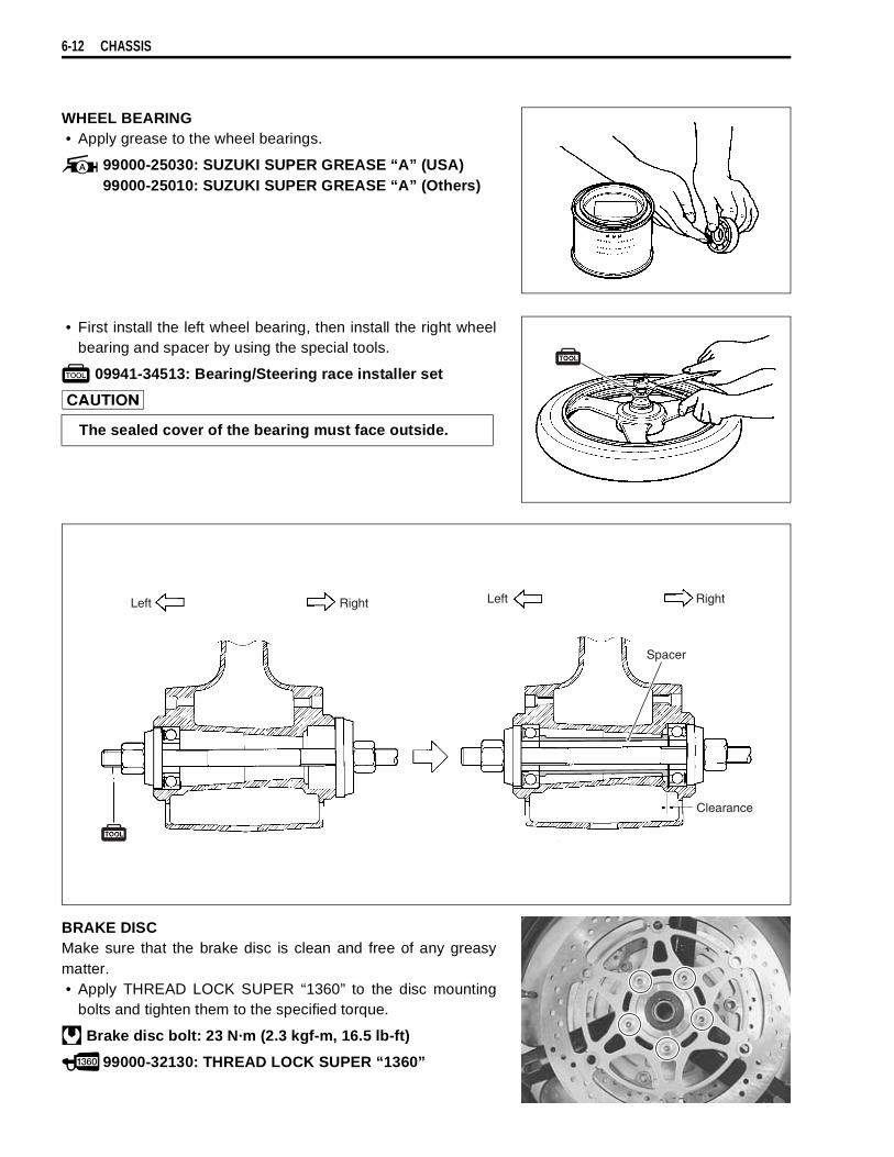
6-12 CHASSIS
WHEEL BEARING• Apply grease to the wheel bearings.
99000-25030: SUZUKI SUPER GREASE “A” (USA)99000-25010: SUZUKI SUPER GREASE “A” (Others)
• First install the left wheel bearing, then install the right wheelbearing and spacer by using the special tools.
09941-34513: Bearing/Steering race installer set
BRAKE DISCMake sure that the brake disc is clean and free of any greasymatter.• Apply THREAD LOCK SUPER “1360” to the disc mounting
bolts and tighten them to the specified torque.
Brake disc bolt: 23 N·m (2.3 kgf-m, 16.5 lb-ft)
99000-32130: THREAD LOCK SUPER “1360”
The sealed cover of the bearing must face outside.
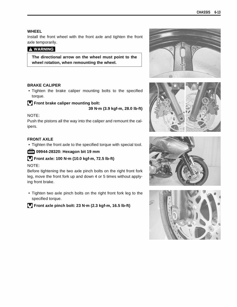
CHASSIS 6-13
WHEELInstall the front wheel with the front axle and tighten the frontaxle temporarily.
BRAKE CALIPER• Tighten the brake caliper mounting bolts to the specified
torque.
Front brake caliper mounting bolt:39 N·m (3.9 kgf-m, 28.0 lb-ft)
NOTE:Push the pistons all the way into the caliper and remount the cal-ipers.
FRONT AXLE• Tighten the front axle to the specified torque with special tool.
09944-28320: Hexagon bit 19 mm
Front axle: 100 N·m (10.0 kgf-m, 72.5 lb-ft)
NOTE:Before tightening the two axle pinch bolts on the right front forkleg, move the front fork up and down 4 or 5 times without apply-ing front brake.
• Tighten two axle pinch bolts on the right front fork leg to thespecified torque.
Front axle pinch bolt: 23 N·m (2.3 kgf-m, 16.5 lb-ft)
The directional arrow on the wheel must point to thewheel rotation, when remounting the wheel.
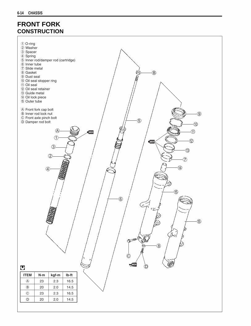
6-14 CHASSIS
FRONT FORKCONSTRUCTION
ITEM N·m kgf-m lb-ft
23 2.3 16.5
20 2.0 14.5
23 2.3 16.5
20 2.0 14.5
O-ring Washer Spacer Spring Inner rod/damper rod (cartridge) Inner tube Slide metal Gasket Dust seal Oil seal stopper ring Oil seal Oil seal retainer Guide metal Oil lock piece Outer tube
Front fork cap bolt Inner rod lock nut Front axle pinch bolt Damper rod bolt
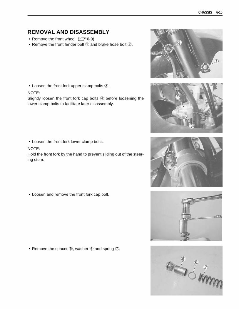
CHASSIS 6-15
REMOVAL AND DISASSEMBLY• Remove the front wheel. ( 6-9)• Remove the front fender bolt
and brake hose bolt
.
• Loosen the front fork upper clamp bolts
.
NOTE:Slightly loosen the front fork cap bolts
before loosening thelower clamp bolts to facilitate later disassembly.
• Loosen the front fork lower clamp bolts.
NOTE:Hold the front fork by the hand to prevent sliding out of the steer-ing stem.
• Loosen and remove the front fork cap bolt.
• Remove the spacer
, washer
and spring
.
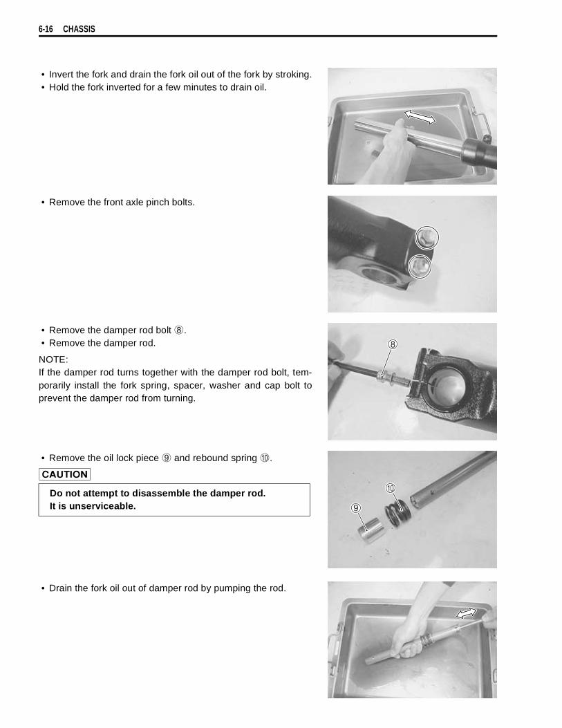
6-16 CHASSIS
• Invert the fork and drain the fork oil out of the fork by stroking.• Hold the fork inverted for a few minutes to drain oil.
• Remove the front axle pinch bolts.
• Remove the damper rod bolt
.• Remove the damper rod.
NOTE:If the damper rod turns together with the damper rod bolt, tem-porarily install the fork spring, spacer, washer and cap bolt toprevent the damper rod from turning.
• Remove the oil lock piece
and rebound spring
.
• Drain the fork oil out of damper rod by pumping the rod.
Do not attempt to disassemble the damper rod.It is unserviceable.
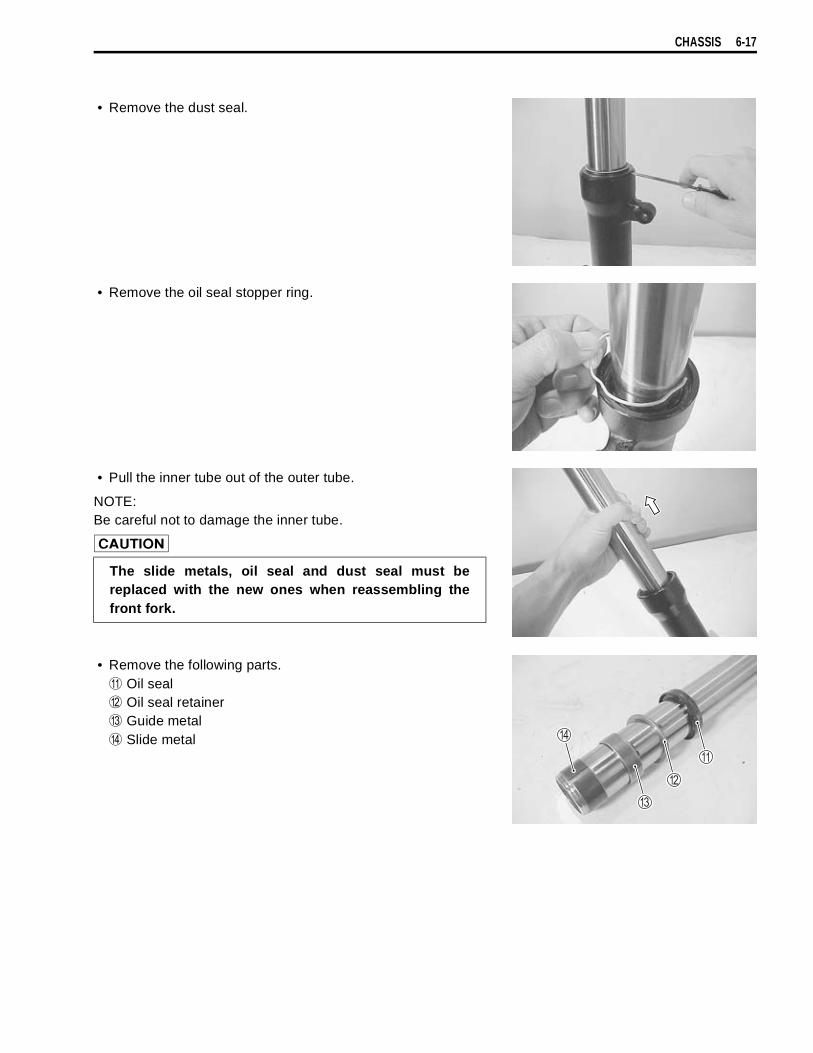
CHASSIS 6-17
• Remove the dust seal.
• Remove the oil seal stopper ring.
• Pull the inner tube out of the outer tube.
NOTE:Be careful not to damage the inner tube.
• Remove the following parts.
Oil seal
Oil seal retainer
Guide metal
Slide metal
The slide metals, oil seal and dust seal must bereplaced with the new ones when reassembling thefront fork.
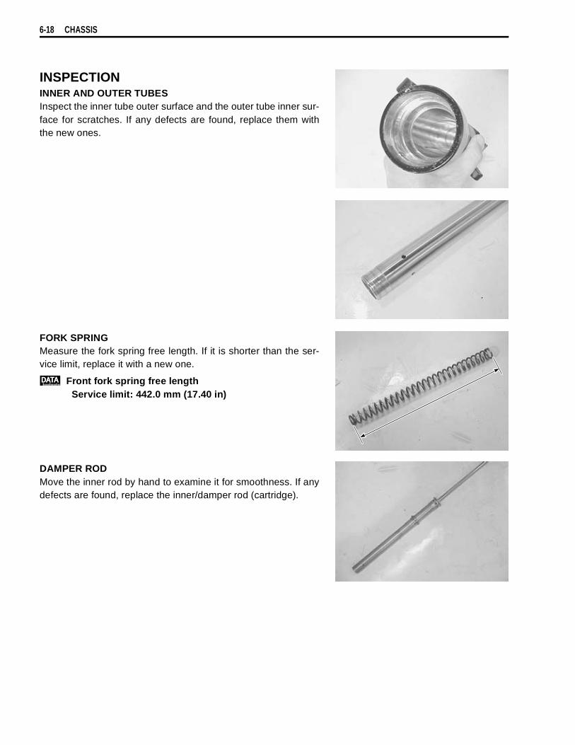
6-18 CHASSIS
INSPECTIONINNER AND OUTER TUBESInspect the inner tube outer surface and the outer tube inner sur-face for scratches. If any defects are found, replace them withthe new ones.
FORK SPRINGMeasure the fork spring free length. If it is shorter than the ser-vice limit, replace it with a new one.
Front fork spring free lengthService limit: 442.0 mm (17.40 in)
DAMPER RODMove the inner rod by hand to examine it for smoothness. If anydefects are found, replace the inner/damper rod (cartridge).
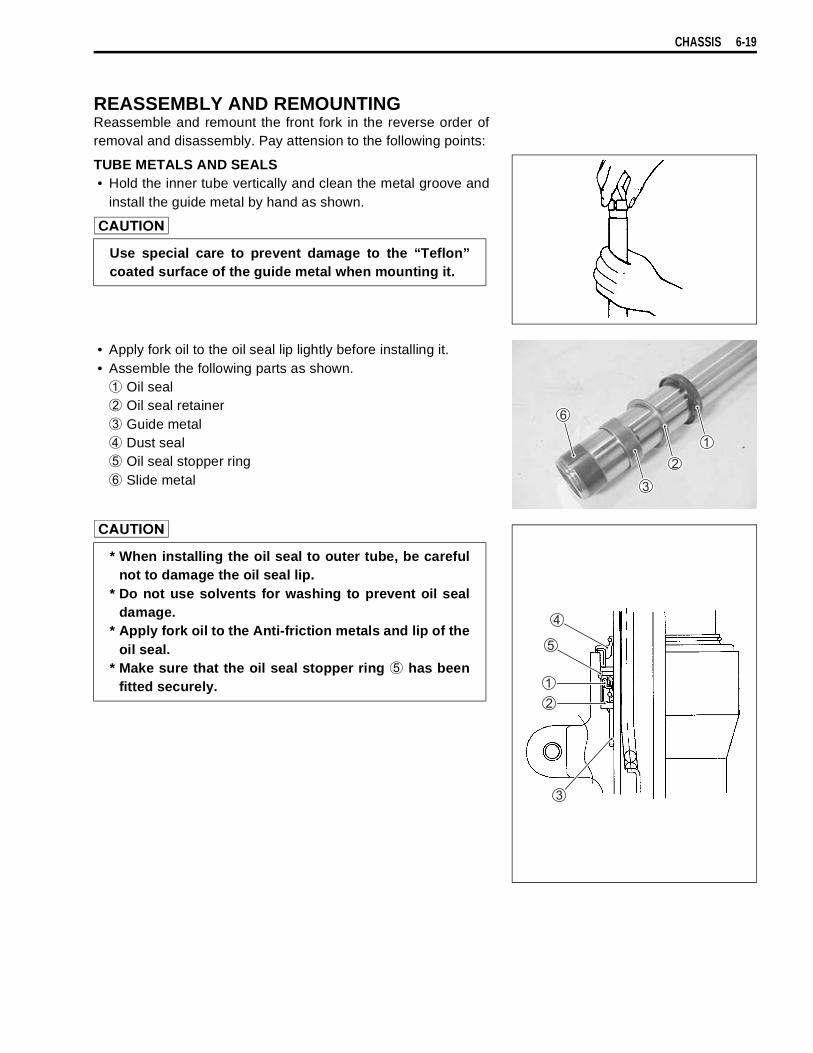
CHASSIS 6-19
REASSEMBLY AND REMOUNTINGReassemble and remount the front fork in the reverse order ofremoval and disassembly. Pay attension to the following points:
TUBE METALS AND SEALS• Hold the inner tube vertically and clean the metal groove and
install the guide metal by hand as shown.
• Apply fork oil to the oil seal lip lightly before installing it.• Assemble the following parts as shown.
Oil seal
Oil seal retainer
Guide metal
Dust seal
Oil seal stopper ring
Slide metal
Use special care to prevent damage to the “Teflon”coated surface of the guide metal when mounting it.
* When installing the oil seal to outer tube, be carefulnot to damage the oil seal lip.
* Do not use solvents for washing to prevent oil sealdamage.
* Apply fork oil to the Anti-friction metals and lip of theoil seal.
* Make sure that the oil seal stopper ring
has beenfitted securely.

6-20 CHASSIS
• Insert the inner tube into the outer tube and fit the oil seal anddust seal with the special tool.
09940-52861: Front fork oil seal installer
NOTE:Stamped mark on the oil seal should face outside.
DAMPER ROD BOLT• Install the rebound spring and oil lock piece to the damper
rod.
NOTE:When installing the rebound spring, the smaller inner diameterof spring must seat the stopper of damper rod.
• Insert the inner rod/damper rod (cartridge) into the outer tube.• Apply THREAD LOCK “1342” to the damper rod bolt and
tighten it to the specified torque.
99000-32050: THREAD LOCK “1342”
Damper rod bolt: 20 N·m (2.0 kgf-m, 14.5 lb-ft)
NOTE:If the damper rod turns together with the damper rod bolt, tem-porarily install the fork spring, spacer, washer and cap bolt toprevent the damper rod from turning.
FORK OIL• Place the front fork vertically without spring.• Compress the front fork fully.• Pour the specified front fork oil into the front fork up to the top
of the inner rod.
99000-99001-SS8: SUZUKI FORK OIL SS-8
Use a new damper rod bolt gasket
to prevent oilleakage.

CHASSIS 6-21
• Move the inner rod slowly more than ten times until no moreair bubbles come out from the oil.
09940-52841: Inner rod holder
NOTE:Refill the front fork oil up to the top of the inner tube in oder tofind air bubbles while bleeding air.
• Move the inner tube up and down several strokes until nomore bubbles come out from the oil.
• Keep the front fork vertically and leave it during 5 – 6 minutes.
NOTE:* Always keep the oil level over the cartridge top end, or air may
enter the cartridge during this procedure. * Take extream attention to pump out air completely.
• Hold the front fork vertically and adjust the fork oil level withthe special tool.
NOTE:When adjusting the fork oil level, remove the fork spring andcompress the inner tube fully.
09943-74111: Front fork oil level gauge
Fork oil level: 133.0 mm (5.24 in)Capacity (each leg): 505.0 ml (17.07/17.78 US/lmp oz)
99000-99001-SS8: SUZUKI FORK OIL SS-8
FORK SPRING• Pull the inner rod up with the inner rod holder.
09940-52841: Inner rod holder

6-22 CHASSIS
• Install the fork spring.NOTE:The smaller end of the fork spring should be at the bottom of thefront fork.
FRONT FORK CAP BOLT• Install the washer
and spacer
.
• Adjust the height
of the inner rod threads by turning thelock nut
as shown.
: 10.5 mm (0.41 in)
• Tighten the front fork cap bolt to seat at lock nut by hand tight-ening.
• Hold the front fork cap bolt, tighten the lock nut to the speci-fied torque.
Inner rod lock nut : 20 N·m (2.0 kgf-m, 14.5 lb-ft)
• Apply fork oil lightly to the O-ring.
• Tighten the front fork cap bolt temporarily.
Use a new O-ring to prevent oil leakage.
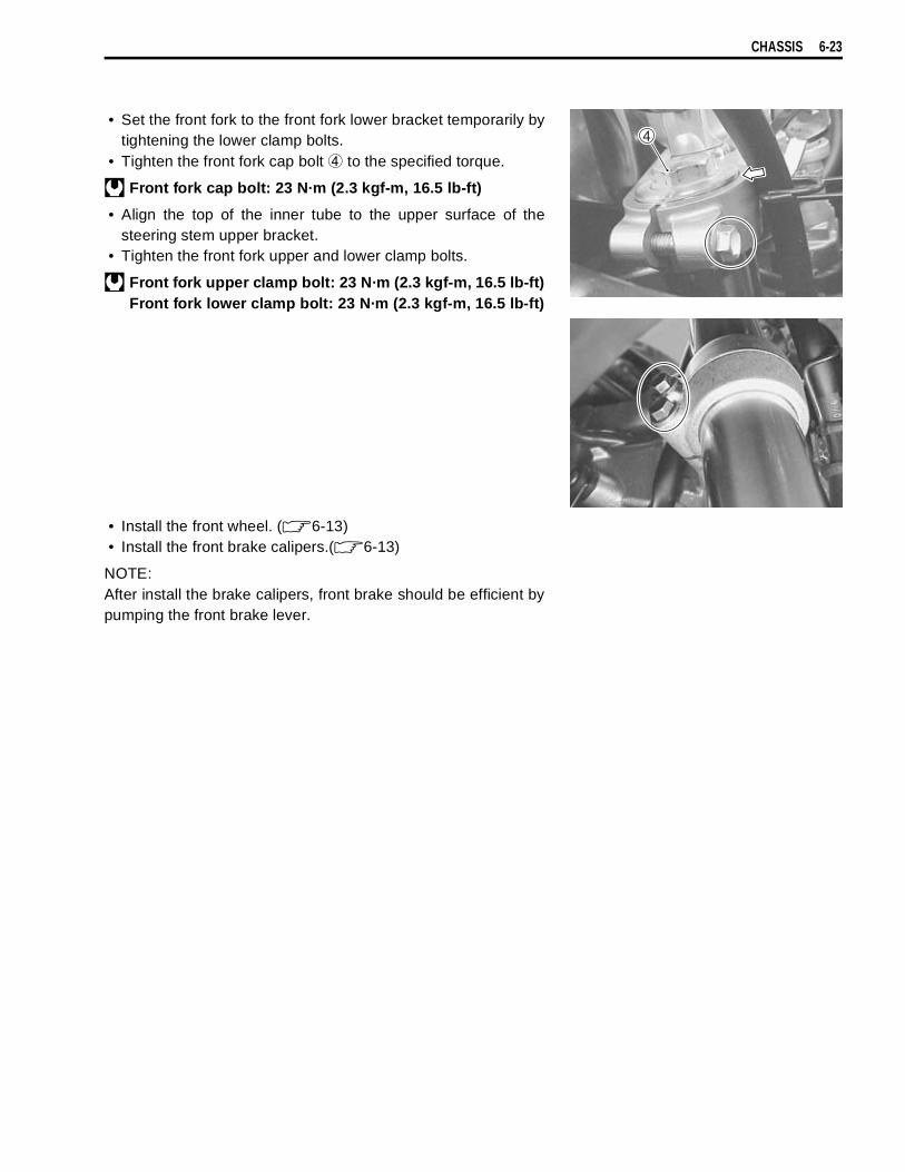
CHASSIS 6-23
• Set the front fork to the front fork lower bracket temporarily bytightening the lower clamp bolts.
• Tighten the front fork cap bolt
to the specified torque.
Front fork cap bolt: 23 N·m (2.3 kgf-m, 16.5 lb-ft)
• Align the top of the inner tube to the upper surface of thesteering stem upper bracket.
• Tighten the front fork upper and lower clamp bolts.
Front fork upper clamp bolt: 23 N·m (2.3 kgf-m, 16.5 lb-ft)Front fork lower clamp bolt: 23 N·m (2.3 kgf-m, 16.5 lb-ft)
• Install the front wheel. ( 6-13)• Install the front brake calipers.( 6-13)
NOTE:After install the brake calipers, front brake should be efficient bypumping the front brake lever.
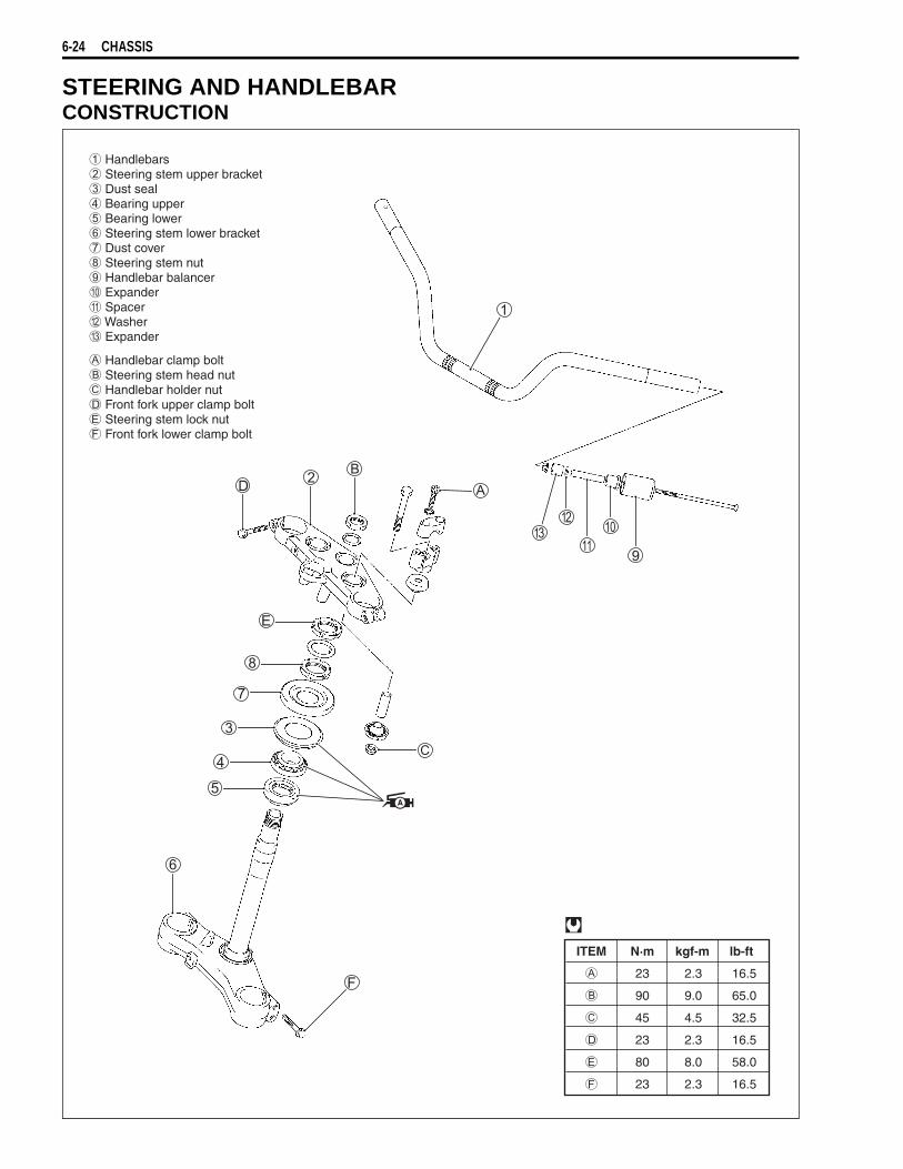
6-24 CHASSIS
STEERING AND HANDLEBARCONSTRUCTION
ITEM N·m kgf-m lb-ft
23 2.3 16.5
90 9.0 65.0
45 4.5 32.5
23 2.3 16.5
80 8.0 58.0
23 2.3 16.5
Handlebars Steering stem upper bracket Dust seal Bearing upper Bearing lower Steering stem lower bracket Dust cover Steering stem nut Handlebar balancer Expander Spacer Washer Expander
Handlebar clamp bolt Steering stem head nut Handlebar holder nut Front fork upper clamp bolt Steering stem lock nut Front fork lower clamp bolt
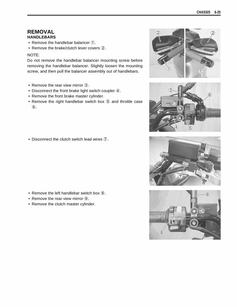
CHASSIS 6-25
REMOVALHANDLEBARS• Remove the handlebar balancer
.• Remove the brake/clutch lever covers
.
NOTE:Do not remove the handlebar balancer mounting screw beforeremoving the handlebar balancer. Slightly loosen the mountingscrew, and then pull the balancer assembly out of handlebars.
• Remove the rear view mirror
.• Disconnect the front brake light switch coupler
.• Remove the front brake master cylinder.• Remove the right handlebar switch box
and throttle case
.
• Disconnect the clutch switch lead wires
.
• Remove the left handlebar switch box
.• Remove the rear view mirror
.• Remove the clutch master cylinder.
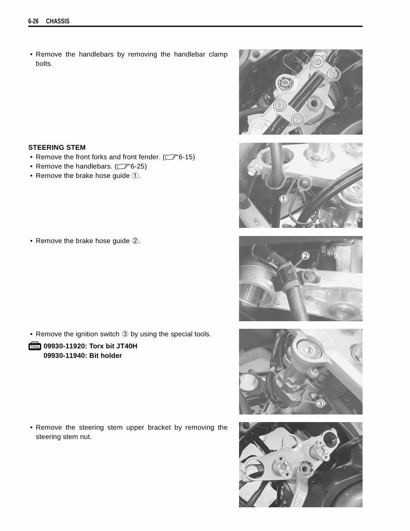
6-26 CHASSIS
• Remove the handlebars by removing the handlebar clampbolts.
STEERING STEM• Remove the front forks and front fender. ( 6-15)• Remove the handlebars. ( 6-25)• Remove the brake hose guide
.
• Remove the brake hose guide
.
• Remove the ignition switch
by using the special tools.
09930-11920: Torx bit JT40H09930-11940: Bit holder
• Remove the steering stem upper bracket by removing thesteering stem nut.
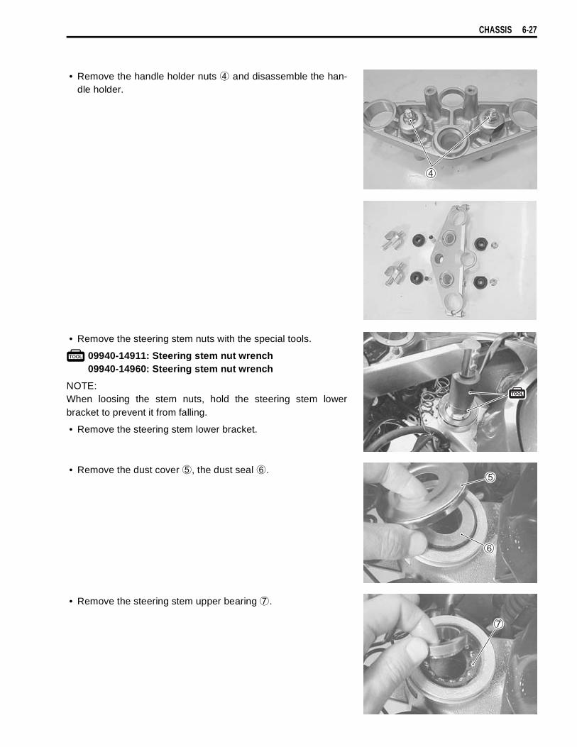
CHASSIS 6-27
• Remove the handle holder nuts
and disassemble the han-dle holder.
• Remove the steering stem nuts with the special tools.
09940-14911: Steering stem nut wrench09940-14960: Steering stem nut wrench
NOTE:When loosing the stem nuts, hold the steering stem lowerbracket to prevent it from falling.
• Remove the steering stem lower bracket.
• Remove the dust cover
, the dust seal
.
• Remove the steering stem upper bearing
.
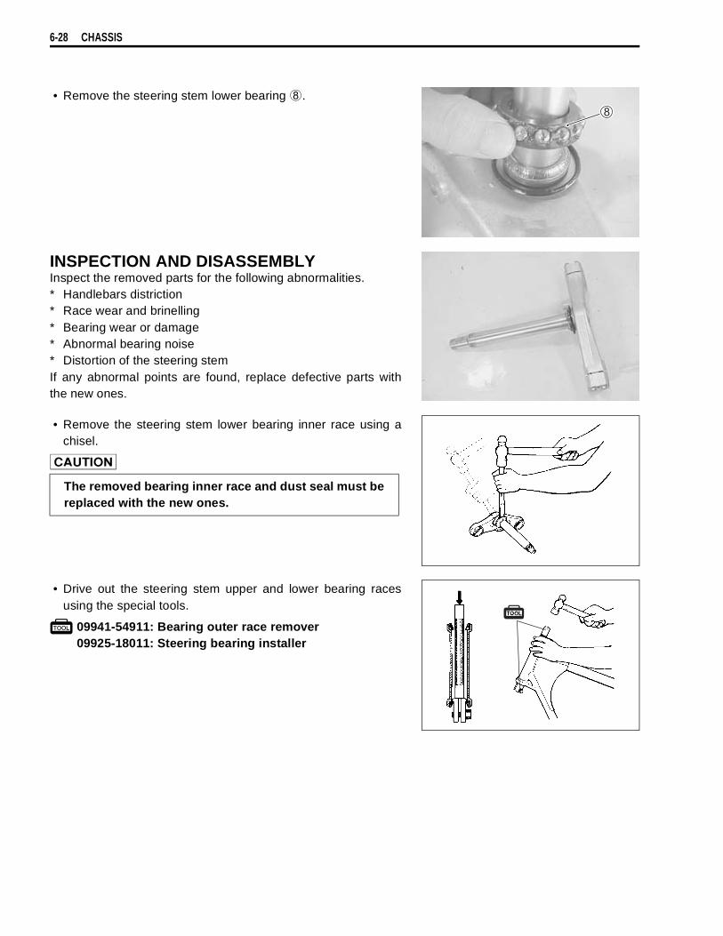
6-28 CHASSIS
• Remove the steering stem lower bearing
.
INSPECTION AND DISASSEMBLYInspect the removed parts for the following abnormalities.* Handlebars distriction* Race wear and brinelling* Bearing wear or damage* Abnormal bearing noise* Distortion of the steering stemIf any abnormal points are found, replace defective parts withthe new ones.
• Remove the steering stem lower bearing inner race using achisel.
• Drive out the steering stem upper and lower bearing racesusing the special tools.
09941-54911: Bearing outer race remover09925-18011: Steering bearing installer
The removed bearing inner race and dust seal must bereplaced with the new ones.
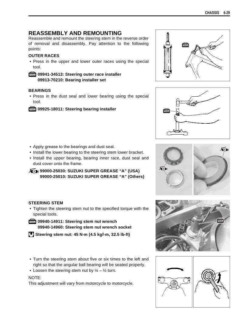
CHASSIS 6-29
REASSEMBLY AND REMOUNTINGReassemble and remount the steering stem in the reverse orderof removal and disassembly. Pay attention to the followingpoints:
OUTER RACES• Press in the upper and lower outer races using the special
tool.
09941-34513: Steering outer race installer09913-70210: Bearing installer set
BEARINGS• Press in the dust seal and lower bearing using the special
tool.
09925-18011: Steering bearing installer
• Apply grease to the bearings and dust seal.• Install the lower bearing to the steering stem lower bracket.• Install the upper bearing, bearing inner race, dust seal and
dust cover onto the frame.
99000-25030: SUZUKI SUPER GREASE “A” (USA)99000-25010: SUZUKI SUPER GREASE “A” (Others)
STEERING STEM• Tighten the steering stem nut to the specified torque with the
special tools.
09940-14911: Steering stem nut wrench09940-14960: Steering stem nut wrench socket
Steering stem nut: 45 N·m (4.5 kgf-m, 32.5 lb-ft)
• Turn the steering stem about five or six times to the left andright so that the angular ball bearing will be seated properly.
• Loosen the steering stem nut by ¼ – ½ turn.
NOTE:This adjustment will vary from motorcycle to motorcycle.

6-30 CHASSIS
• Install the washer.
NOTE:When installing the washer, align the stopper lug to the grooveof the steering stem.
• Install the steering stem lock nut and tighten it to the specifiedtorque with the special tools.
09940-14911: Steering stem nut wrench09940-14960: Steering stem nut wrench socket
Steering stem lock nut: 80 N·m (8.0 kgf-m, 58.0 lb-ft)
• Reassemble the handlebar holders to the steering stem upperbracket.
• Tighten the handlebar holder nuts to the specified torque.
Handlebar holder nut: 45 N·m (4.5 kgf-m, 32.5 lb-ft)
NOTE:Before tightening the nut to the specified torque, temporarilyinstall the handlebars in order to align both holders.
• Install the steering stem upper bracket and tighten the steer-ing stem nut lightly.
• Install the ignition switch
and harness guide
. ( 7-31)
• Install the front fork to the steering stem and tighten the lowerclamp bolts temporarily.
• Tighten the steering stem head nut to the specified toupue.
Steering stem head nut: 90 N·m (9.0 kgf-m, 65.0 lb-ft)
• Remount the front forks and the front fender. ( 6-23)
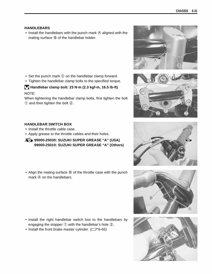
CHASSIS 6-31
HANDLEBARS• Install the handlebars with the punch mark
aligned with themating surface
of the handlebar holder.
• Set the punch mark
on the handlebar clamp forward.• Tighten the handlebar clamp bolts to the specified torque.
Handlebar clamp bolt: 23 N·m (2.3 kgf-m, 16.5 lb-ft)
NOTE:When tightening the handlebar clamp bolts, first tighten the bolt
and then tighten the bolt
.
HANDLEBAR SWITCH BOX• Install the throttle cable case. • Apply grease to the throttle cables and their holes.
99000-25030: SUZUKI SUPER GREASE “A” (USA)99000-25010: SUZUKI SUPER GREASE “A” (Others)
• Align the mating surface
of the throttle case with the punchmark
on the handlebars.
• Install the right handlebar switch box to the handlebars byengaging the stopper
with the handlebar’s hole
.• Install the front brake master cylinder. ( 6-65)

6-32 CHASSIS
• Install the left handlebar switch box to the handlebars byengaging the stopper
with the handlebars hole
.• Install the clutch master cylinder with the proper clutch hose
routing.
• Install the handlebar balancers and the rear view mirrors.(Handlbar balancer installation: 8-31)
• Install the front wheel. ( 6-13)
STEERING TENSION ADJUSTMENTCheck the steering movement in the following procedure.• By supporting the motorcycle with a jack, lift the front wheel
until it is off the floor by 20 – 30 mm (0.8 – 1.2 in).• Check to make sure that the cables and wire harnesses are
properly routed.• With the front wheel in the straight ahead state, hitch the
spring scale (special tool) on one handlebar grip end asshown in the figure and read the graduation when the handle-bar starts moving. Do the same on the other grip end.
Initial force: 200 – 500 grams
09940-92720: Spring scale
• If the initial force read on the scale when the handlebar startsturning is either too heavy or too light, adjust it till it satisfiesthe specification.
1)First, loosen the front fork upper and lower clamp bolts, steer-ing stem head nut and steering stem lock nut, and then adjustthe steering stem nut by loosening or tightening it.
2)Tighten the steering stem lock nut, stem head nut and frontfork upper and lower clamp bolts to the specified torque andre-check the initial force with the spring scale according to thepreviously described procedure.
3)If the initial force is found within the specified range, adjust-ment has been completed.
NOTE:Hold the front fork legs, move them back and forth and makesure that the steering is not loose.
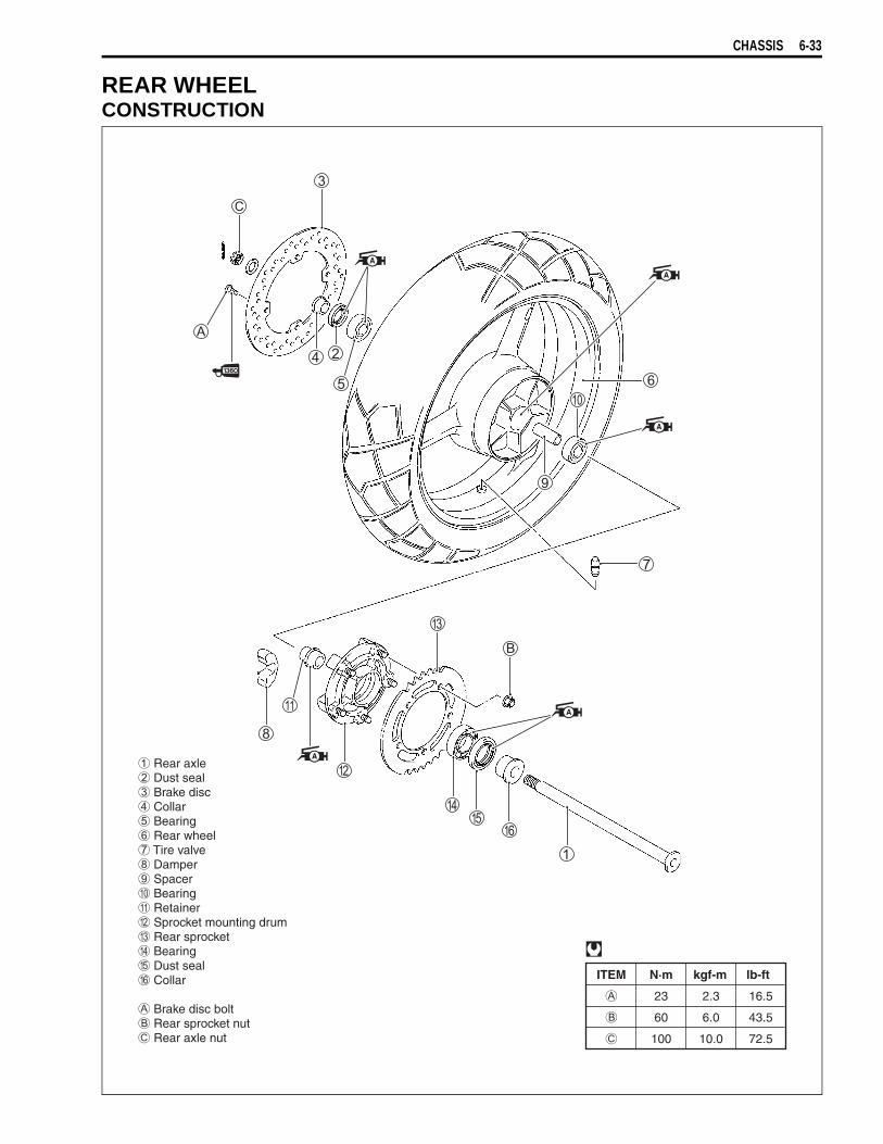
CHASSIS 6-33
REAR WHEELCONSTRUCTION
ITEM N·m kgf-m lb-ft
23 2.3 16.5
60 6.0 43.5
100 10.0 72.5
Rear axle Dust seal Brake disc Collar Bearing Rear wheel Tire valve Damper Spacer Bearing Retainer Sprocket mounting drum Rear sprocket Bearing Dust seal Collar
Brake disc bolt Rear sprocket nut Rear axle nut
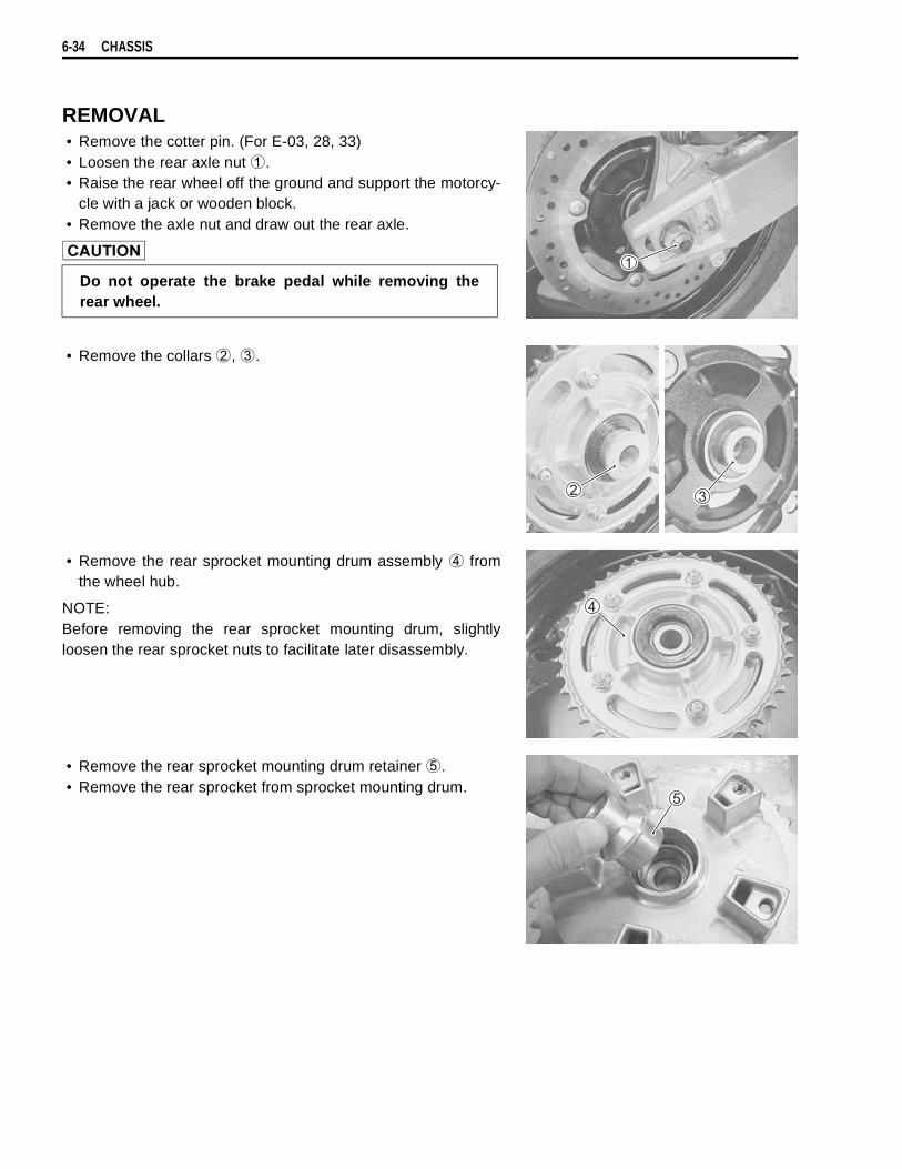
6-34 CHASSIS
REMOVAL• Remove the cotter pin. (For E-03, 28, 33)• Loosen the rear axle nut
.• Raise the rear wheel off the ground and support the motorcy-
cle with a jack or wooden block.• Remove the axle nut and draw out the rear axle.
• Remove the collars
,
.
• Remove the rear sprocket mounting drum assembly
fromthe wheel hub.
NOTE:Before removing the rear sprocket mounting drum, slightlyloosen the rear sprocket nuts to facilitate later disassembly.
• Remove the rear sprocket mounting drum retainer
.• Remove the rear sprocket from sprocket mounting drum.
Do not operate the brake pedal while removing therear wheel.
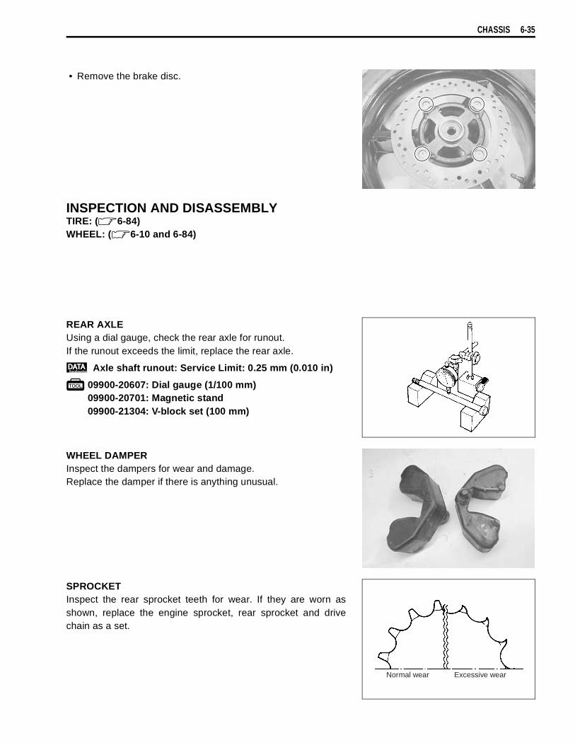
CHASSIS 6-35
• Remove the brake disc.
INSPECTION AND DISASSEMBLYTIRE: ( 6-84)WHEEL: ( 6-10 and 6-84)
REAR AXLEUsing a dial gauge, check the rear axle for runout.If the runout exceeds the limit, replace the rear axle.
Axle shaft runout: Service Limit: 0.25 mm (0.010 in)
09900-20607: Dial gauge (1/100 mm)09900-20701: Magnetic stand09900-21304: V-block set (100 mm)
WHEEL DAMPERInspect the dampers for wear and damage.Replace the damper if there is anything unusual.
SPROCKETInspect the rear sprocket teeth for wear. If they are worn asshown, replace the engine sprocket, rear sprocket and drivechain as a set.
Normal wear Excessive wear
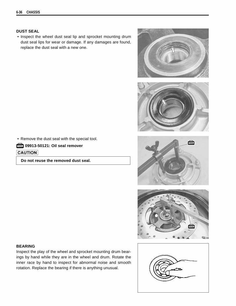
6-36 CHASSIS
DUST SEAL• Inspect the wheel dust seal lip and sprocket mounting drum
dust seal lips for wear or damage. If any damages are found,replace the dust seal with a new one.
• Remove the dust seal with the special tool.
09913-50121: Oil seal remover
BEARINGInspect the play of the wheel and sprocket mounting drum bear-ings by hand while they are in the wheel and drum. Rotate theinner race by hand to inspect for abnormal noise and smoothrotation. Replace the bearing if there is anything unusual.
Do not reuse the removed dust seal.

CHASSIS 6-37
• Remove the sprocket mounting drum bearing and wheel bear-ings by using the special tool.
09921-20240: Bearing remover set
The removed bearings must be replaced with the newones.
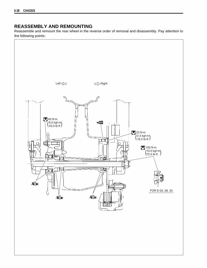
6-38 CHASSIS
REASSEMBLY AND REMOUNTINGReassemble and remount the rear wheel in the reverse order of removal and disassembly. Pay attention tothe following points:
Left Right
( )
( )
( )
FOR E-03, 28, 33
60 N.m 6.0 kgf-m 43.5 lb-ft
23 N.m 2.3 kgf-m 16.5 lb-ft
100 N.m 10.0 kgf-m 72.5 lb-ft

CHASSIS 6-39
BEARING• Apply grease to the bearings before installing.
99000-25030: SUZUKI SUPER GREASE “A” (USA)99000-25010: SUZUKI SUPER GREASE “A” (Others)
• Install the new bearing to the sprocket mounting drum usingthe special tool.
09924-84510: Bearing installer set
NOTE:When installing the bearing, non-sealed side of bearing mustface the special tool.
• First install the right wheel bearing, then install the left wheelbearing and spacer using the special tool.
09941-34513: Bearing/Steering race installer set
The sealed cover of the bearing must face outside.
Left Right Left Right
Spacer
ClearanceBearinginstaller
Spacer
Bearing
Wheel hub
Clearance

6-40 CHASSIS
DUST SEAL• Install the new dust seal using the special tool.
09913-70210: Bearing installer set
• Apply SUZUKI SUPER GREASE “A” to the dust seal lipsbefore assembling rear wheel.
99000-25030: SUZUKI SUPER GREASE “A” (USA)99000-25010: SUZUKI SUPER GREASE “A” (Others)
NOTE:When installing the dust seals, the stamped mark of dust sealmust face the special tool.
BRAKE DISCMake sure that the brake disc is clean and free of any greasymatter.• Apply THREAD LOCK SUPER “1360” to the disc bolts and
tighten them to the specified torque.
99000-32130: THREAD LOCK SUPER “1360”
Brake disc bolt: 23 N·m (2.3 kgf-m, 16.5 lb-ft)
REAR SPROCKET• Tighten the sprocket mounting nuts to the specified torque.
Rear sprocket nut: 60 N·m (6.0 kgf-m, 43.5 lb-ft)
NOTE:Stamped mark
on the sprocket must face outside.
• Apply SUZUKI SUPER GREASE “A” to the rear sprocketmounting retainer.
• Install the rear sprocket mounting drum retainer.• Apply SUZUKI SUPER GREASE “A” to the contacting surface
between the rear wheel and the sprocket drum.
99000-25030: SUZUKI SUPER GREASE “A” (USA)99000-25010: SUZUKI SUPER GREASE “A” (Others)
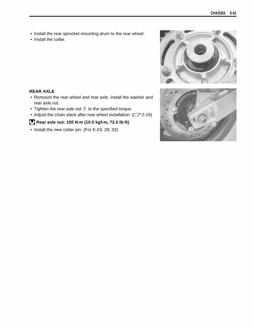
CHASSIS 6-41
• Install the rear sprocket mounting drum to the rear wheel.• Install the collar.
REAR AXLE• Remount the rear wheel and rear axle, install the washer and
rear axle nut.• Tighten the rear axle nut
to the specified torque.• Adjust the chain slack after rear wheel installation. ( 2-19)
Rear axle nut: 100 N·m (10.0 kgf-m, 72.5 lb-ft)
• Install the new cotter pin. (For E-03, 28, 33)
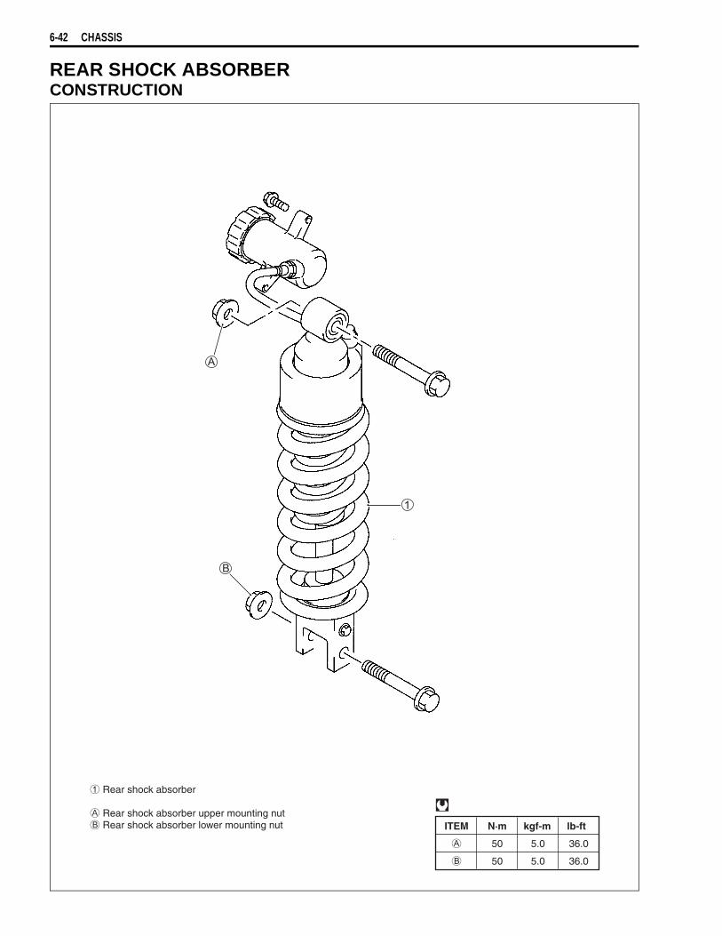
6-42 CHASSIS
REAR SHOCK ABSORBERCONSTRUCTION
ITEM N·m kgf-m lb-ft
50 5.0 36.0
50 5.0 36.0
Rear shock absorber
Rear shock absorber upper mounting nut Rear shock absorber lower mounting nut
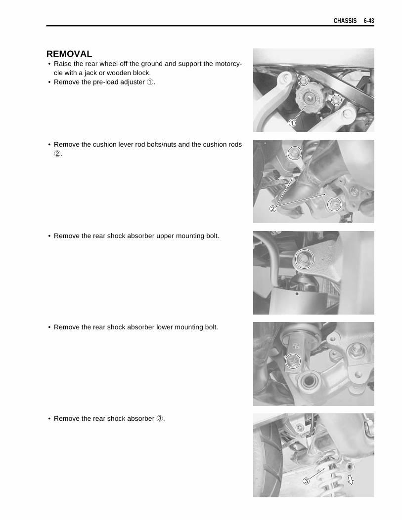
CHASSIS 6-43
REMOVAL• Raise the rear wheel off the ground and support the motorcy-
cle with a jack or wooden block.• Remove the pre-load adjuster
.
• Remove the cushion lever rod bolts/nuts and the cushion rods
.
• Remove the rear shock absorber upper mounting bolt.
• Remove the rear shock absorber lower mounting bolt.
• Remove the rear shock absorber
.

6-44 CHASSIS
INSPECTIONInspect the shock absorber body and bushing for damage andoil leakage.If any defects are found, replace the shock absorber with a newone.
REAR SHOCK ABSORBER DISPOSAL
GAS PRESSURE RELEASE• Mark the drill hole at
, shown in the illustration, with a centerpunch.
• Cover the rear shock absorber with a transparent vinyl bag
.• Hold the rear shock absorber
with a vice.• Make a hole with a 3 mm drill.
Do not attempt to disassemble the rear shockabsorber unit. It is unserviceable.
The rear shock unit contains high-pressure nitrogengas. Mishandling can cause explosion.* Keep away from fire and heat. High gas pressure
caused by heat can cause an explosion.* Release gas pressure before disposing. 7 mm
(0.27 in)
Wear eye protection to protect your eyes fromreleased gas and metal chips.
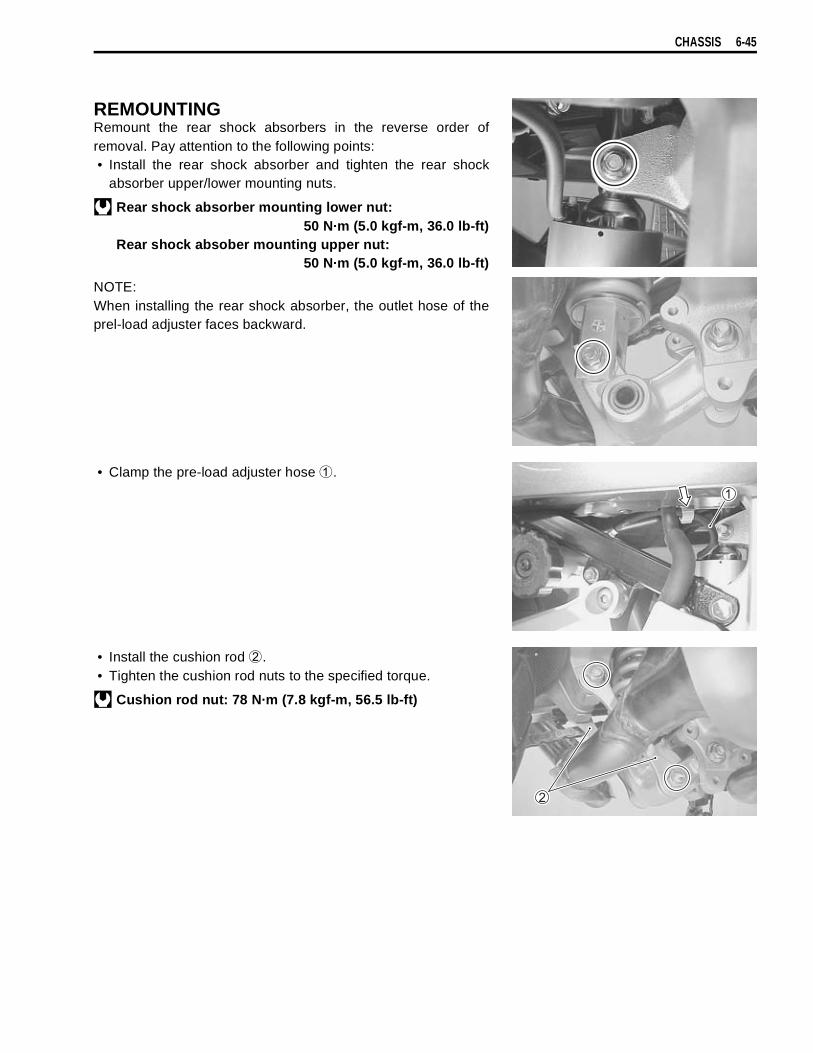
CHASSIS 6-45
REMOUNTINGRemount the rear shock absorbers in the reverse order ofremoval. Pay attention to the following points:• Install the rear shock absorber and tighten the rear shock
absorber upper/lower mounting nuts.
Rear shock absorber mounting lower nut:50 N·m (5.0 kgf-m, 36.0 lb-ft)
Rear shock absober mounting upper nut:50 N·m (5.0 kgf-m, 36.0 lb-ft)
NOTE:When installing the rear shock absorber, the outlet hose of theprel-load adjuster faces backward.
• Clamp the pre-load adjuster hose
.
• Install the cushion rod
.• Tighten the cushion rod nuts to the specified torque.
Cushion rod nut: 78 N·m (7.8 kgf-m, 56.5 lb-ft)
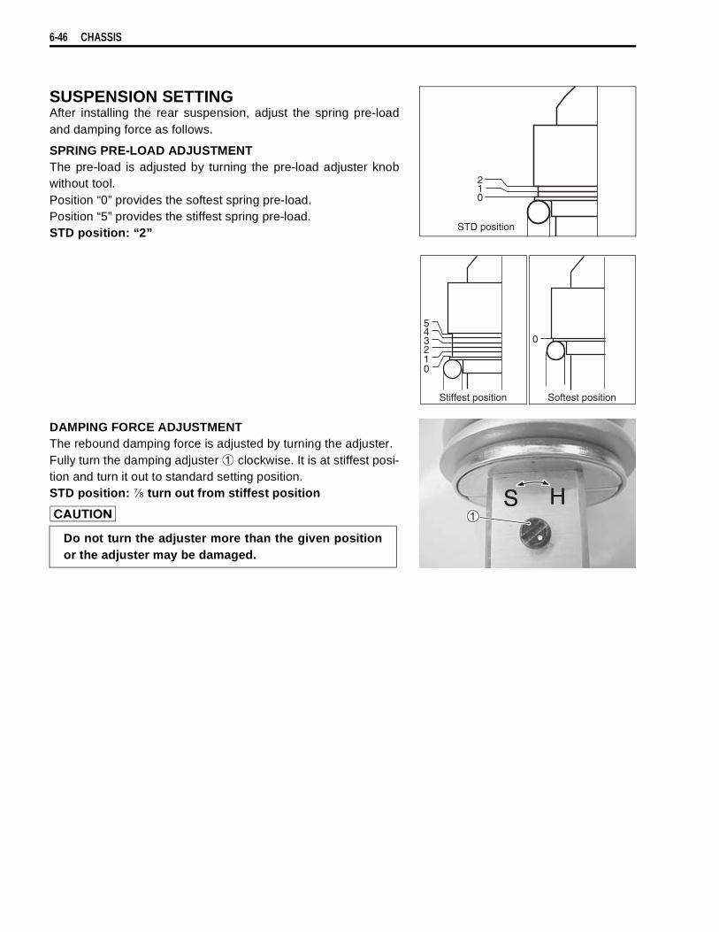
6-46 CHASSIS
SUSPENSION SETTINGAfter installing the rear suspension, adjust the spring pre-loadand damping force as follows.
SPRING PRE-LOAD ADJUSTMENTThe pre-load is adjusted by turning the pre-load adjuster knobwithout tool.Position “0” provides the softest spring pre-load.Position “5” provides the stiffest spring pre-load.STD position: “2”
DAMPING FORCE ADJUSTMENTThe rebound damping force is adjusted by turning the adjuster.Fully turn the damping adjuster
clockwise. It is at stiffest posi-tion and turn it out to standard setting position.STD position: turn out from stiffest position
STD position
2
01
Stiffest position Softest position
021
345
0
Do not turn the adjuster more than the given positionor the adjuster may be damaged.
HHSS
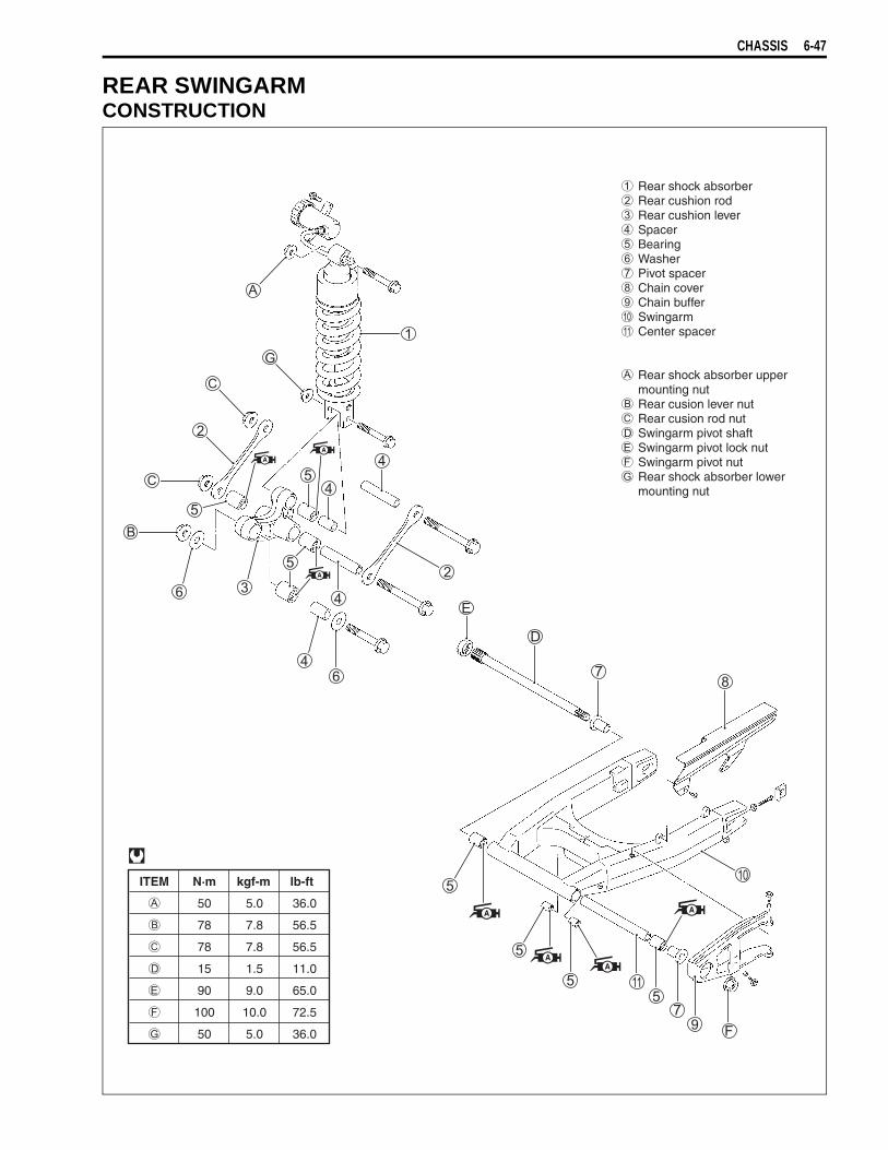
CHASSIS 6-47
REAR SWINGARMCONSTRUCTION
ITEM N·m kgf-m lb-ft
50 5.0 36.0
78 7.8 56.5
78 7.8 56.5
15 1.5 11.0
90 9.0 65.0
100 10.0 72.5
50 5.0 36.0
Rear shock absorber Rear cushion rod Rear cushion lever Spacer Bearing Washer Pivot spacer Chain cover Chain buffer Swingarm Center spacer
Rear shock absorber uppermounting nut
Rear cusion lever nut Rear cusion rod nut Swingarm pivot shaft Swingarm pivot lock nut Swingarm pivot nut Rear shock absorber lower
mounting nut

6-48 CHASSIS
REMOVAL• Remove the exhaust pipe and exhaust muffler. ( 3-7)• Raise the rear wheel off the ground and support the motorcy-
cle with a jack or wooden block.• Remove the rear wheel. ( 6-34)• Remove the rear brake hose guide
.
• Remove the cushion rods
.• Remove the shock absorber
.• Remove the cushion lever
.
• Remove the swingarm pivot shaft lock nut by using the spe-cial tool.
09940-14940: Swingarm pivot thrust adjuster socketwrench
• Hold the swingarm pivot shaft
and remove the swingarmpivot nut
.• Remove the swingarm pivot shaft by using the special tool.
09944-28320: Hexagon bit 19 mm
• Remove the chain cover.

CHASSIS 6-49
• Remove the mud guard
.• Remove the brake hose guide
.
• Remove the chain buffer
.
INSPECTION AND DISASSEMBLYSPACER• Remove the spacers from swingarm and cushion lever.• Inspect the spacers for any flaws or other damage. If any
defects are found, replace the spacers with the new ones.
CHAIN BUFFERInspect the chain buffer for damage and excessive wear. If anydefects are found, replace the chain buffer with a new one.

6-50 CHASSIS
SWINGARM BEARINGInsert the spacer into bearing and check the play when movingthe spacer up and down.If excessive play is noted, replace the bearing with a new one.
• Remove the swingarm pivot bearing and spacer with the spe-cial tools.
09923-74511: Bearing remover09930-30102: Sliding shaft
• Remove the cushion rod bearings by using the special tool.
09913-73210: Bearing remover09930-30102: Sliding shaft
SWINGARM PIVOT SHAFTUsing a dial gauge, check the pivot shaft runout and replace it ifthe runout exceeds the limit.
09900-20607: Dial gauge (1/100 mm, 10 mm)09900-20701: Magnetic stand09900-21304: V-block (100 mm)
Swingarm pivot shaft runout:Service limit: 0.3 mm (0.01 in)
Do not reuse the removed bearings.
Do not reuse the removed bearings.
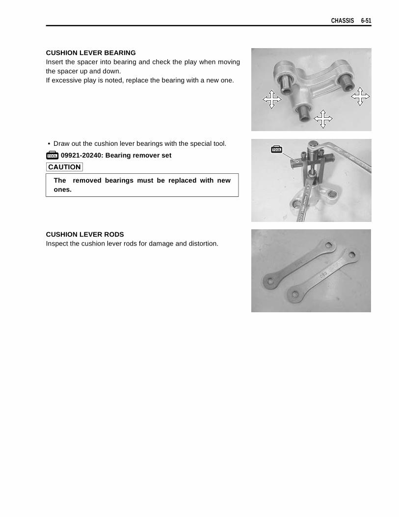
CHASSIS 6-51
CUSHION LEVER BEARINGInsert the spacer into bearing and check the play when movingthe spacer up and down.If excessive play is noted, replace the bearing with a new one.
• Draw out the cushion lever bearings with the special tool.
09921-20240: Bearing remover set
CUSHION LEVER RODSInspect the cushion lever rods for damage and distortion.
The removed bearings must be replaced with newones.
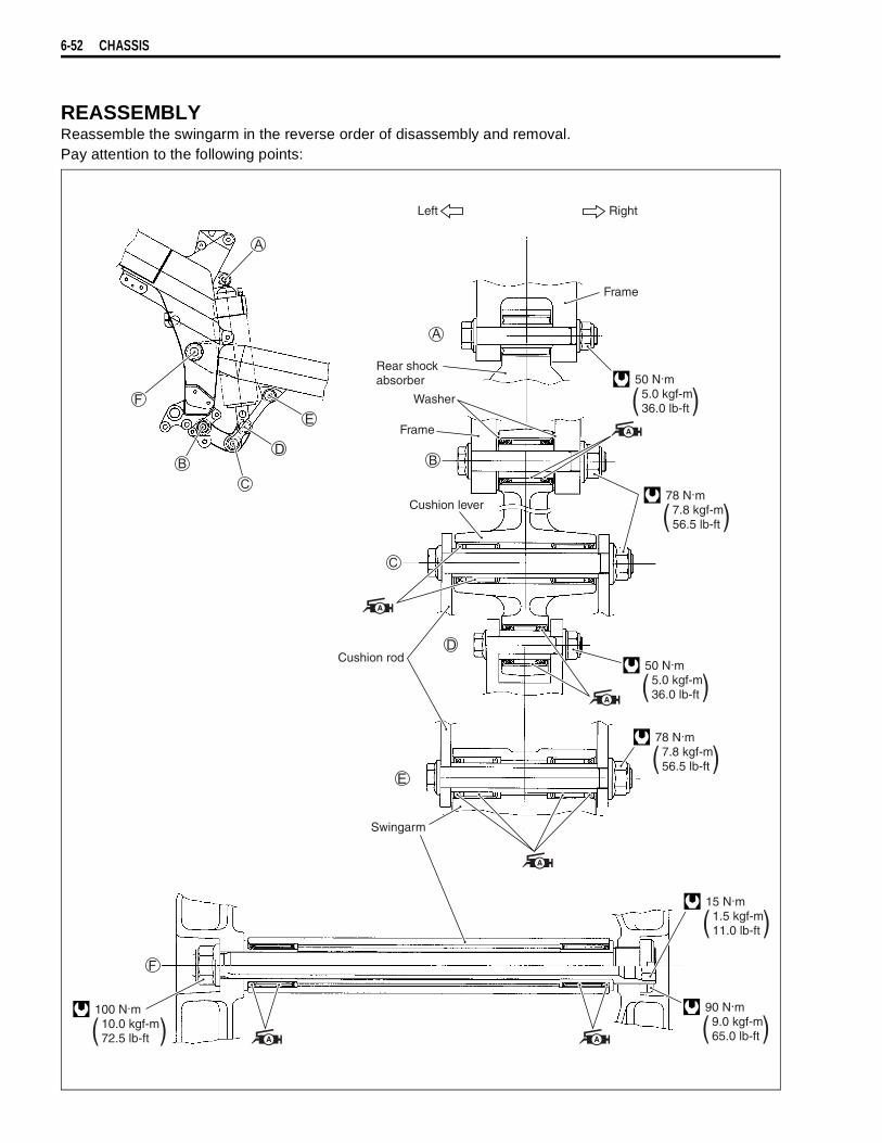
6-52 CHASSIS
REASSEMBLYReassemble the swingarm in the reverse order of disassembly and removal.Pay attention to the following points:
Left Right
Frame
Rear shockabsorber
Washer
Frame
Cushion lever
Cushion rod
Swingarm
50 N.m 5.0 kgf-m 36.0 lb-ft ( )
50 N.m 5.0 kgf-m 36.0 lb-ft ( )
90 N.m 9.0 kgf-m 65.0 lb-ft ( )
78 N.m 7.8 kgf-m 56.5 lb-ft ( )
78 N.m 7.8 kgf-m 56.5 lb-ft ( )
15 N.m 1.5 kgf-m 11.0 lb-ft ( )
100 N.m 10.0 kgf-m 72.5 lb-ft ( )

CHASSIS 6-53
SWINGARM BEARING• Install the bearings and spacer into the swingarm pivot all
together by using the special tool.
09941-34513: Steering race installer
NOTE:When installing the bearing, the stamped mark on the bearingmust face the special tool.
• Install the cushion rod bearing with the special tool.
09941-34513: Steering race installer
NOTE:When installing the bearing, the dust seal that is embedded inthe bearing must face outside.
CUSHION LEVER BEARING• Press the bearings into the cushion lever with the special tool.
09941-34513: Steering race installer
NOTE:When installing the bearing, the dust seal that is embedded inthe bearing must face outside.
• Apply grease to the bearings and spacers.
99000-25030: SUZUKI SUPER GREASE “A” (USA)99000-25010: SUZUKI SUPER GREASE “A” (Others)

6-54 CHASSIS
REMOUNTINGRemount the swingarm in the reverse order of disassembly andremoval, and pay attention to the following points:
SWINGARM• Insert the swingarm pivot shaft and tighten it to the specified
torque by using the special tool.
Swingarm pivot shaft: 15 N·m (1.5 kgf-m, 11.0 lb-ft)
09944-28320: Hexagon bit 19 mm
• Hold the swingarm pivot shaft
and tighten the swingarmpivot nut
to the specified torque.
Swingarm pivot nut: 100 N·m (10.0 kgf-m, 72.5 lb-ft)
• Tighten the swingarm pivot lock nut to the specified torquewith the special tool.
09940-14940: Swingarm pivot thrust adjuster socketwrench
Swingarm pivot lock nut: 90 N·m (9.0 kgf-m, 65.0 lb-ft)
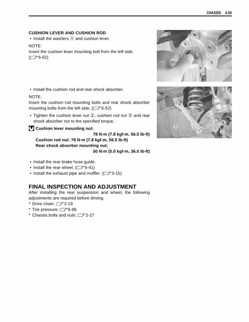
CHASSIS 6-55
CUSHION LEVER AND CUSHION ROD• Install the washers
and cushion lever.
NOTE:Insert the cushion lever mounting bolt from the left side.( 6-52)
• Install the cushion rod and rear shock absorber.
NOTE:Insert the cushion rod mounting bolts and rear shock absorbermounting bolts from the left side. ( 6-52)
• Tighten the cushion lever nut
, cushion rod nut
and rearshock absorber nut to the specified torque.
Cushion lever mounting nut:78 N·m (7.8 kgf-m, 56.5 lb-ft)
Cushion rod nut: 78 N·m (7.8 kgf-m, 56.5 lb-ft)Rear shock absorber mounting nut:
50 N·m (5.0 kgf-m, 36.0 lb-ft)
• Install the rear brake hose guide.• Install the rear wheel. ( 6-41)• Install the exhaust pipe and muffler. ( 3-15)
FINAL INSPECTION AND ADJUSTMENTAfter installing the rear suspension and wheel, the followingadjustments are required before driving.* Drive chain: 2-19* Tire pressure: 6-86* Chassis bolts and nuts: 2-27
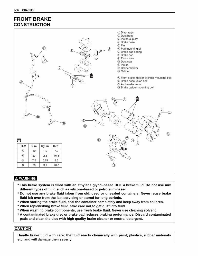
6-56 CHASSIS
FRONT BRAKECONSTRUCTION
* This brake system is filled with an ethylene glycol-based DOT 4 brake fluid. Do not use mixdifferent types of fluid such as silicone-based or petroleum-based.
* Do not use any brake fluid taken from old, used or unsealed containers. Never reuse brakefluid left over from the last servicing or stored for long periods.
* When storing the brake fluid, seal the container completely and keep away from children.* When replenishing brake fluid, take care not to get dust into fluid.* When washing brake components, use fresh brake fluid. Never use cleaning solvent.* A contaminated brake disc or brake pad reduces braking performance. Discard contaminated
pads and clean the disc with high quality brake cleaner or neutral detergent.
Handle brake fluid with care: the fluid reacts chemically with paint, plastics, rubber materialsetc. and will damage then severly.
ITEM N·m kgf-m lb-ft
10 1.0 7.0
23 2.3 16.5
7.5 0.75 5.5
39 3.9 28.0
Diaphragm Dust boot Piston/cup set Brake hose Pin Pad mounting pin Brake pad spring Brake pad Piston seal Dust seal Piston Caliper holder Caliper
Front brake master cylinder mounting bolt Brake hose union bolt Air bleeder valve Brake caliper mounting bolt
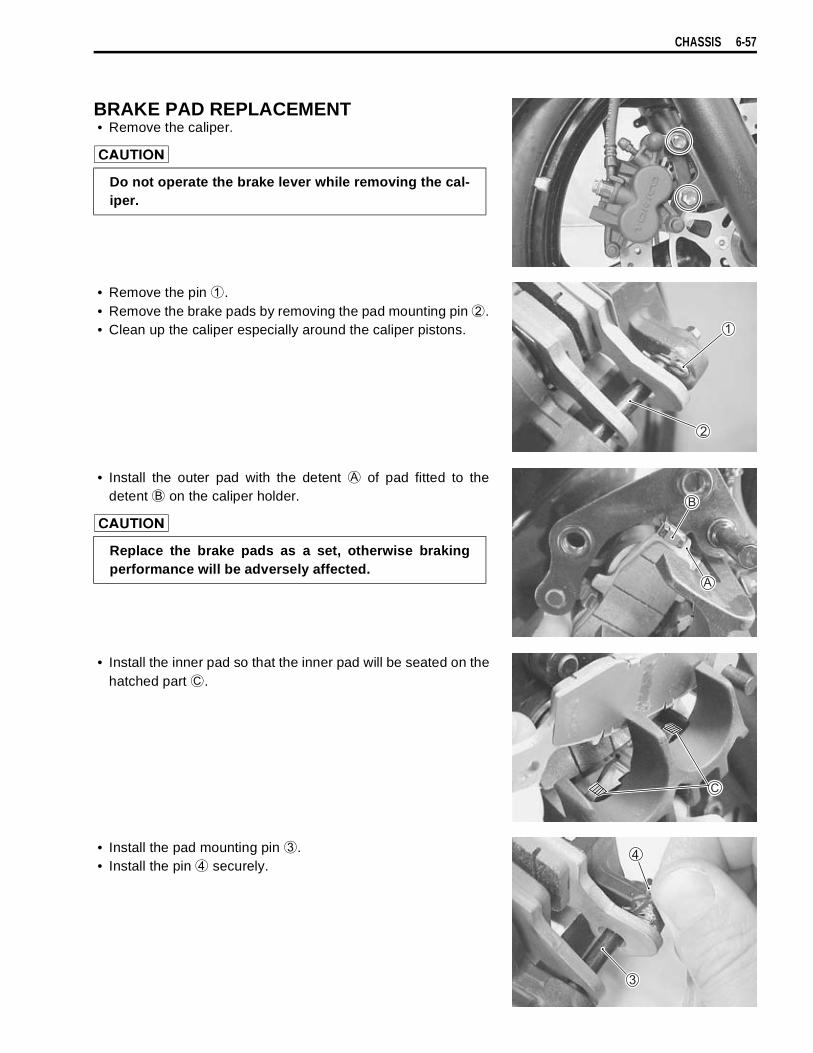
CHASSIS 6-57
BRAKE PAD REPLACEMENT• Remove the caliper.
• Remove the pin
.• Remove the brake pads by removing the pad mounting pin
.• Clean up the caliper especially around the caliper pistons.
• Install the outer pad with the detent
of pad fitted to thedetent
on the caliper holder.
• Install the inner pad so that the inner pad will be seated on thehatched part
.
• Install the pad mounting pin
.• Install the pin
securely.
Do not operate the brake lever while removing the cal-iper.
Replace the brake pads as a set, otherwise brakingperformance will be adversely affected.
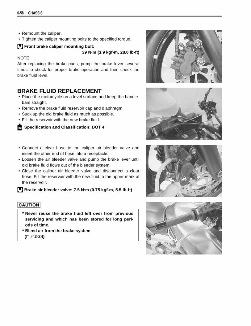
6-58 CHASSIS
• Remount the caliper.• Tighten the caliper mounting bolts to the specified torque.
Front brake caliper mounting bolt:39 N·m (3.9 kgf-m, 28.0 lb-ft)
NOTE:After replacing the brake pads, pump the brake lever severaltimes to check for proper brake operation and then check thebrake fluid level.
BRAKE FLUID REPLACEMENT• Place the motorcycle on a level surface and keep the handle-
bars straight.• Remove the brake fluid reservoir cap and diaphragm.• Suck up the old brake fluid as much as possible.• Fill the reservoir with the new brake fluid.
Specification and Classification: DOT 4
• Connect a clear hose to the caliper air bleeder valve andinsert the other end of hose into a receptacle.
• Loosen the air bleeder valve and pump the brake lever untilold brake fluid flows out of the bleeder system.
• Close the caliper air bleeder valve and disconnect a clearhose. Fill the reservoir with the new fluid to the upper mark ofthe reservoir.
Brake air bleeder valve: 7.5 N·m (0.75 kgf-m, 5.5 lb-ft)
* Never reuse the brake fluid left over from previousservicing and which has been stored for long peri-ods of time.
* Bleed air from the brake system. ( 2-24)

CHASSIS 6-59
CALIPER REMOVAL AND DISASSEMBLY• Drain the brake fluid. ( 6-58)• Remove the brake pads. ( 6-57)• Disconnect the brake hoses by removing the brake hose
union bolts.
NOTE:Place a rag underneath the union bolt on the brake caliper tocatch any spilt brake fluid.
• Remove the brake calipers by removing the caliper mountingbolts.
• Remove the caliper holder
.• Remove the pad spring
.
• Place a rag over the pistons to prevent them from popping outand then force out the pistons using compressed air.
• Remove the dust seals and piston seals.
Do not reuse the brake fluid left over from previousservicing and stored for long periods of time.
Brake fluid, if it leaks, will interfere with safe runningand discolor painted surfaces. Check the brake hoseand hose joints for cracks and fluid leakage.
Do not use high pressure air to prevent piston dam-age.
Do not reuse the removed dust seals and piston sealsto prevent fluid leakage.
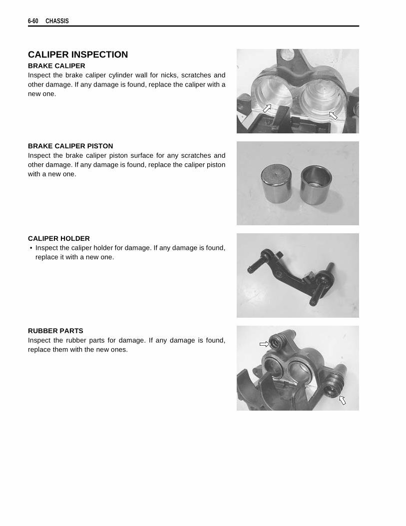
6-60 CHASSIS
CALIPER INSPECTIONBRAKE CALIPERInspect the brake caliper cylinder wall for nicks, scratches andother damage. If any damage is found, replace the caliper with anew one.
BRAKE CALIPER PISTONInspect the brake caliper piston surface for any scratches andother damage. If any damage is found, replace the caliper pistonwith a new one.
CALIPER HOLDER• Inspect the caliper holder for damage. If any damage is found,
replace it with a new one.
RUBBER PARTSInspect the rubber parts for damage. If any damage is found,replace them with the new ones.

CHASSIS 6-61
CALIPER REASSEMBLY AND REMOUNTINGReassemble the caliper in the reverse order of removal and dis-assembly. Pay attention to the following points:• Wash the caliper bores and pistons with specified brake fluid.
Particularly wash the dust seal grooves and piston sealgrooves.
Specification and Classification: DOT 4
PISTON SEAL• Install the piston seals as shown in the illustration.• Install the piston to the caliper.
CALIPER HOLDER• Apply SUZUKI SILICONE GREASE to the caliper holder pin.
99000-25100: SUZUKI SILICONE GREASE
• Install the caliper holder to the caliper.
* Wash the caliper components with fresh brake fluidbefore reassembly. Never use cleaning solvent orgasoline to wash them.
* Do not wipe the brake fluid off after washing thecomponents with a rag.
* When washing the components, use the specifiedbrake fluid. Never use different types of fluid orcleaning solvent such as gasoline, kerosine or theothers.
* Replace the piston seals and dust seals with the newones when reassembly.
* Apply the brake fluid to both seals when installingthem.
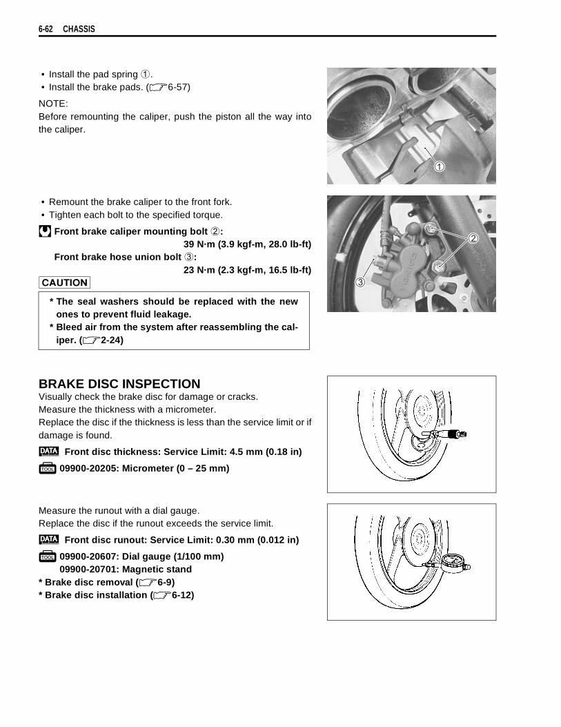
6-62 CHASSIS
• Install the pad spring
.• Install the brake pads. ( 6-57)
NOTE:Before remounting the caliper, push the piston all the way intothe caliper.
• Remount the brake caliper to the front fork.• Tighten each bolt to the specified torque.
Front brake caliper mounting bolt
:39 N·m (3.9 kgf-m, 28.0 lb-ft)
Front brake hose union bolt
:23 N·m (2.3 kgf-m, 16.5 lb-ft)
BRAKE DISC INSPECTIONVisually check the brake disc for damage or cracks.Measure the thickness with a micrometer.Replace the disc if the thickness is less than the service limit or ifdamage is found.
Front disc thickness: Service Limit: 4.5 mm (0.18 in)
09900-20205: Micrometer (0 – 25 mm)
Measure the runout with a dial gauge.Replace the disc if the runout exceeds the service limit.
Front disc runout: Service Limit: 0.30 mm (0.012 in)
09900-20607: Dial gauge (1/100 mm)09900-20701: Magnetic stand
* Brake disc removal ( 6-9)* Brake disc installation ( 6-12)
* The seal washers should be replaced with the newones to prevent fluid leakage.
* Bleed air from the system after reassembling the cal-iper. ( 2-24)

CHASSIS 6-63
MASTER CYLINDER REMOVAL AND DISAS-SEMBLY• Remove the rear view mirror and brake lever cover.• Drain the brake fluid. ( 6-58)• Disconnect the front brake light switch coupler
.
• Place a rag underneath the union bolt on the master cylinderto catch any spilt brake fluid. Remove the brake hose unionbolt and disconnect the brake hose.
• Remove the master cylinder.
• Remove the brake lever
and brake switch
.
• Pull out the dust boot
and remove the snap ring
.
Immediately and completely wipe off any brake fluidcontacting any part of the motorcycle. The fluid reactschemically with paint, plastics and rubber materials,etc. and will damage them severely.
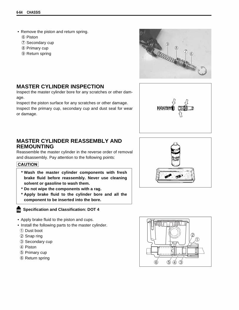
6-64 CHASSIS
• Remove the piston and return spring.
Piston
Secondary cup
Primary cup
Return spring
MASTER CYLINDER INSPECTIONInspect the master cylinder bore for any scratches or other dam-age.Inspect the piston surface for any scratches or other damage.Inspect the primary cup, secondary cup and dust seal for wearor damage.
MASTER CYLINDER REASSEMBLY AND REMOUNTINGReassemble the master cylinder in the reverse order of removaland disassembly. Pay attention to the following points:
Specification and Classification: DOT 4
• Apply brake fluid to the piston and cups.• Install the following parts to the master cylinder.
Dust boot
Snap ring
Secondary cup
Piston
Primary cup
Return spring
* Wash the master cylinder components with freshbrake fluid before reassembly. Never use cleaningsolvent or gasoline to wash them.
* Do not wipe the components with a rag.* Apply brake fluid to the cylinder bore and all the
component to be inserted into the bore.

CHASSIS 6-65
• When remounting the brake master cylinder onto the handle-bars, align the master cylinder holder’s mating surface
withpunch mark
on the handlebars and tighten the upper clampbolt first as shown.
Front brake master cylinder mounting bolt:10 N·m (1.0 kgf-m, 7.0 lb-ft)
• Tighten the union bolt. (Brake hose routing: 8-24)
Brake hose union bolt: 23 N·m (2.3 kgf-m, 16.5 lb-ft)
* The seal washers should be replaced with the newones to prevent fluid leakage.
* Bleed air from the system after reassembling themaster cylinder. ( 2-24)
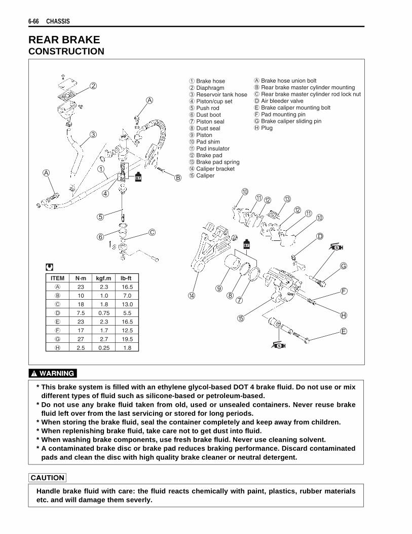
6-66 CHASSIS
REAR BRAKECONSTRUCTION
* This brake system is filled with an ethylene glycol-based DOT 4 brake fluid. Do not use or mixdifferent types of fluid such as silicone-based or petroleum-based.
* Do not use any brake fluid taken from old, used or unsealed containers. Never reuse brakefluid left over from the last servicing or stored for long periods.
* When storing the brake fluid, seal the container completely and keep away from children.* When replenishing brake fluid, take care not to get dust into fluid.* When washing brake components, use fresh brake fluid. Never use cleaning solvent.* A contaminated brake disc or brake pad reduces braking performance. Discard contaminated
pads and clean the disc with high quality brake cleaner or neutral detergent.
Handle brake fluid with care: the fluid reacts chemically with paint, plastics, rubber materialsetc. and will damage them severly.
ITEM N·m kgf.m lb-ft
23 2.3 16.5
10 1.0 7.0
18 1.8 13.0
7.5 0.75 5.5
23 2.3 16.5
17 1.7 12.5
27 2.7 19.5
2.5 0.25 1.8
Brake hose Diaphragm Reservoir tank hose Piston/cup set Push rod Dust boot Piston seal Dust seal Piston Pad shim Pad insulator Brake pad Brake pad spring Caliper bracket Caliper
Brake hose union bolt Rear brake master cylinder mounting Rear brake master cylinder rod lock nut Air bleeder valve Brake caliper mounting bolt Pad mounting pin Brake caliper sliding pin Plug
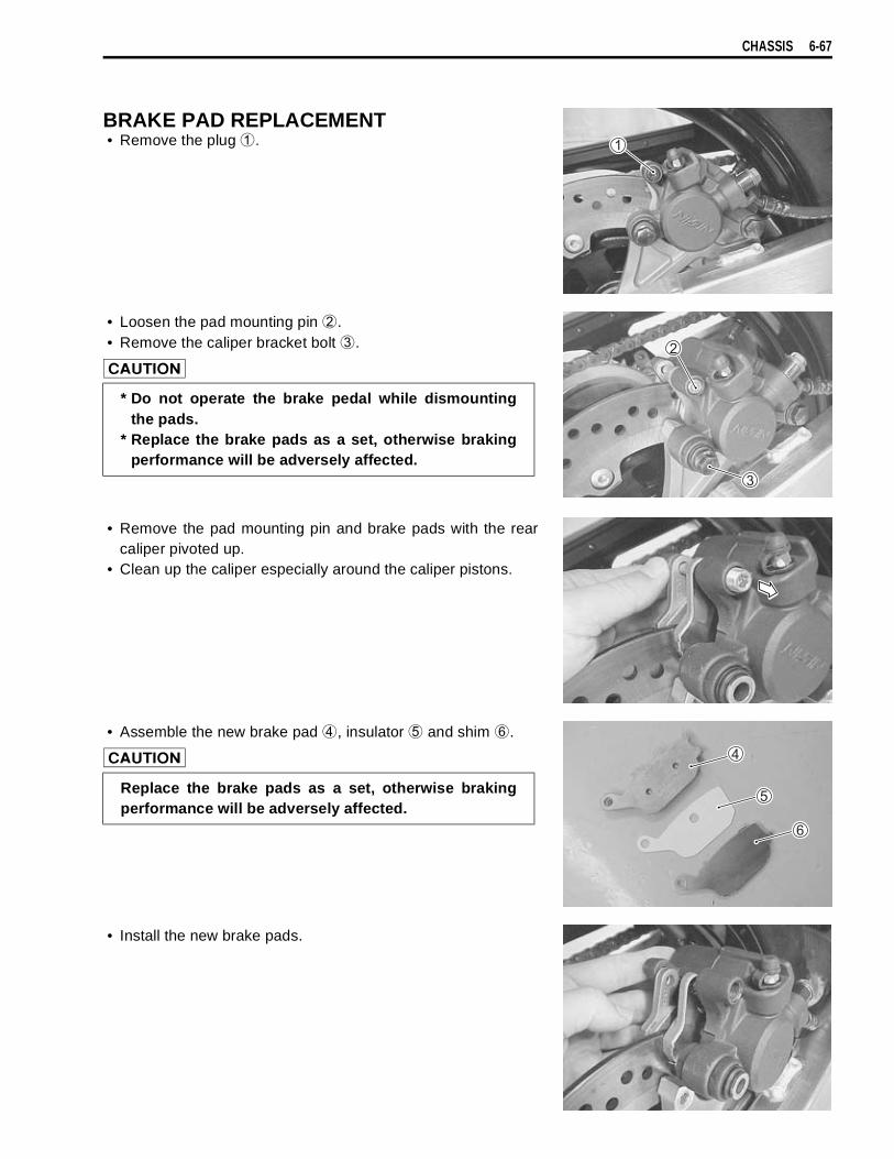
CHASSIS 6-67
BRAKE PAD REPLACEMENT• Remove the plug
.
• Loosen the pad mounting pin
.• Remove the caliper bracket bolt
.
• Remove the pad mounting pin and brake pads with the rearcaliper pivoted up.
• Clean up the caliper especially around the caliper pistons.
• Assemble the new brake pad
, insulator
and shim
.
• Install the new brake pads.
* Do not operate the brake pedal while dismountingthe pads.
* Replace the brake pads as a set, otherwise brakingperformance will be adversely affected.
Replace the brake pads as a set, otherwise brakingperformance will be adversely affected.
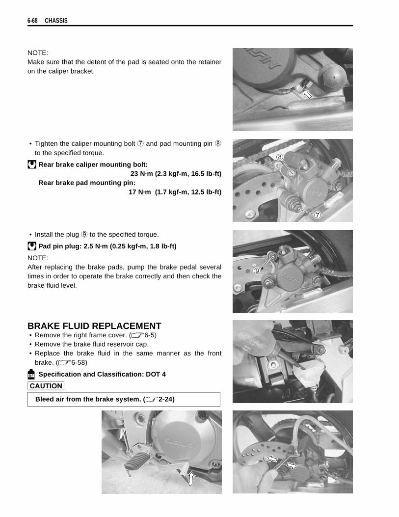
6-68 CHASSIS
NOTE:Make sure that the detent of the pad is seated onto the retaineron the caliper bracket.
• Tighten the caliper mounting bolt
and pad mounting pin
to the specified torque.
Rear brake caliper mounting bolt:23 N·m (2.3 kgf-m, 16.5 lb-ft)
Rear brake pad mounting pin: 17 N·m (1.7 kgf-m, 12.5 lb-ft)
• Install the plug
to the specified torque.
Pad pin plug: 2.5 N·m (0.25 kgf-m, 1.8 lb-ft)
NOTE:After replacing the brake pads, pump the brake pedal severaltimes in order to operate the brake correctly and then check thebrake fluid level.
BRAKE FLUID REPLACEMENT• Remove the right frame cover. ( 6-5)• Remove the brake fluid reservoir cap.• Replace the brake fluid in the same manner as the front
brake. ( 6-58)
Specification and Classification: DOT 4
Bleed air from the brake system. ( 2-24)
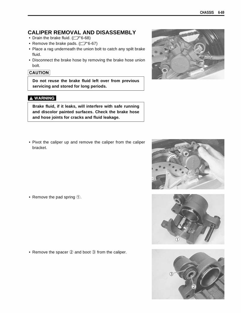
CHASSIS 6-69
CALIPER REMOVAL AND DISASSEMBLY• Drain the brake fluid. ( 6-68)• Remove the brake pads. ( 6-67)• Place a rag underneath the union bolt to catch any spilt brake
fluid.• Disconnect the brake hose by removing the brake hose union
bolt.
• Pivot the caliper up and remove the caliper from the caliperbracket.
• Remove the pad spring
.
• Remove the spacer
and boot
from the caliper.
Do not reuse the brake fluid left over from previousservicing and stored for long periods.
Brake fluid, if it leaks, will interfere with safe runningand discolor painted surfaces. Check the brake hoseand hose joints for cracks and fluid leakage.

6-70 CHASSIS
• Remove the slide pin
.
• Place a rag over the piston to prevent it from popping out andthen force out the piston using compressed air.
• Remove the dust seal
and piston seal
.
CALIPER INSPECTIONBRAKE CALIPERInspect the brake caliper cylinder wall for nicks, scratches andother damage. If any damage is found, replace the caliper with anew one.
BRAKE CALIPER PISTONInspect the brake caliper piston surface for any scratches andother damage. If any damage is found, replace the caliper pistonwith a new one.
Do not use high pressure air to prevent piston dam-age.
Do not reuse the dust seal and piston seal to preventfluid leakage.
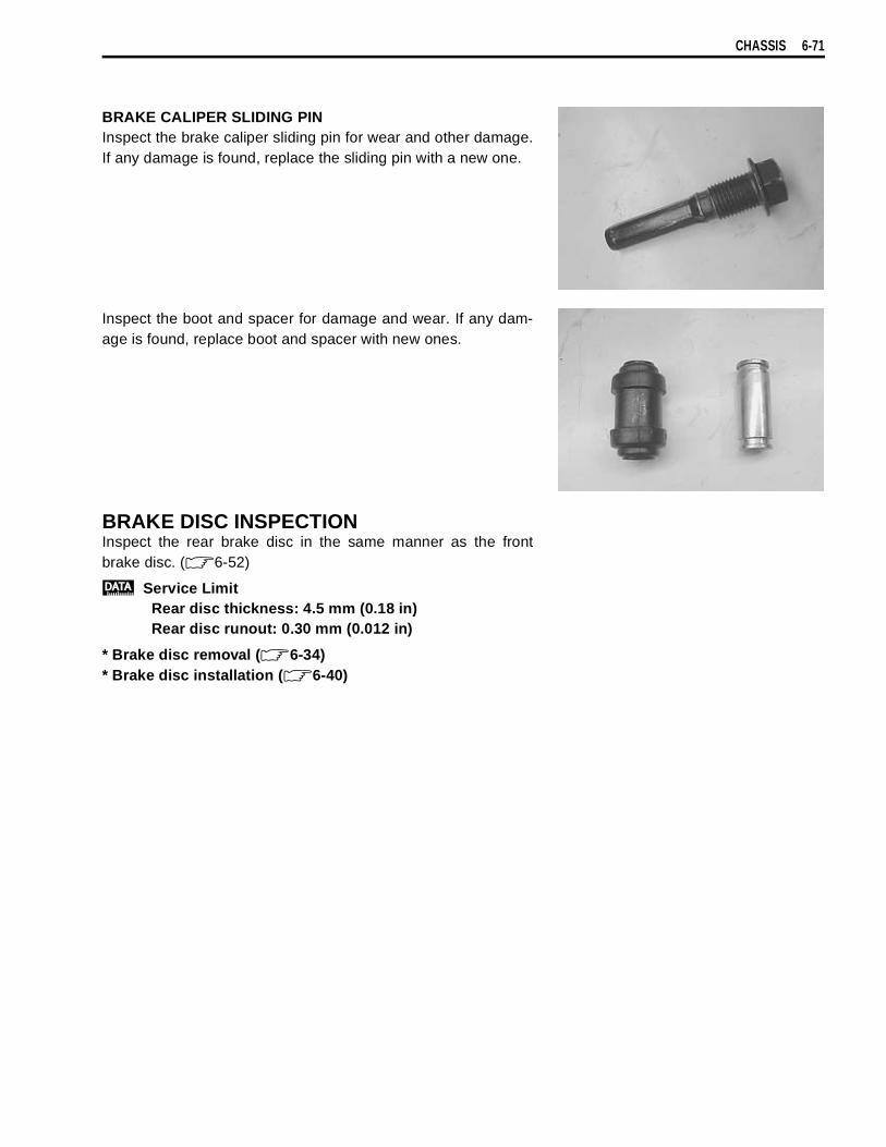
CHASSIS 6-71
BRAKE CALIPER SLIDING PINInspect the brake caliper sliding pin for wear and other damage.If any damage is found, replace the sliding pin with a new one.
Inspect the boot and spacer for damage and wear. If any dam-age is found, replace boot and spacer with new ones.
BRAKE DISC INSPECTIONInspect the rear brake disc in the same manner as the frontbrake disc. ( 6-52)
Service LimitRear disc thickness: 4.5 mm (0.18 in)Rear disc runout: 0.30 mm (0.012 in)
* Brake disc removal ( 6-34)* Brake disc installation ( 6-40)
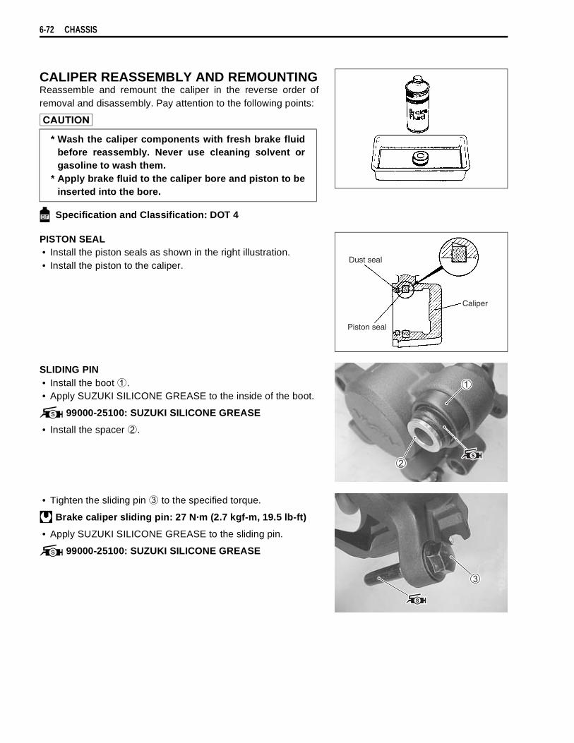
6-72 CHASSIS
CALIPER REASSEMBLY AND REMOUNTINGReassemble and remount the caliper in the reverse order ofremoval and disassembly. Pay attention to the following points:
Specification and Classification: DOT 4
PISTON SEAL• Install the piston seals as shown in the right illustration.• Install the piston to the caliper.
SLIDING PIN• Install the boot
.• Apply SUZUKI SILICONE GREASE to the inside of the boot.
99000-25100: SUZUKI SILICONE GREASE
• Install the spacer
.
• Tighten the sliding pin
to the specified torque.
Brake caliper sliding pin: 27 N·m (2.7 kgf-m, 19.5 lb-ft)
• Apply SUZUKI SILICONE GREASE to the sliding pin.
99000-25100: SUZUKI SILICONE GREASE
* Wash the caliper components with fresh brake fluidbefore reassembly. Never use cleaning solvent orgasoline to wash them.
* Apply brake fluid to the caliper bore and piston to beinserted into the bore.
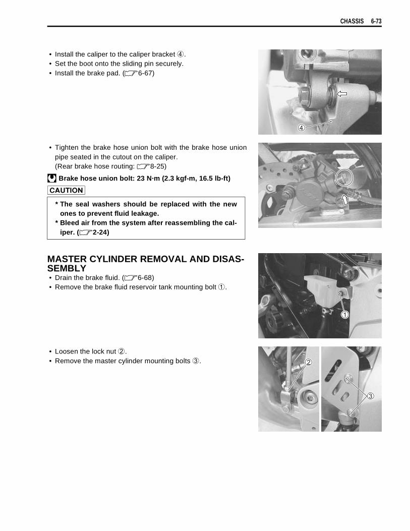
CHASSIS 6-73
• Install the caliper to the caliper bracket
.• Set the boot onto the sliding pin securely.• Install the brake pad. ( 6-67)
• Tighten the brake hose union bolt with the brake hose unionpipe seated in the cutout on the caliper. (Rear brake hose routing: 8-25)
Brake hose union bolt: 23 N·m (2.3 kgf-m, 16.5 lb-ft)
MASTER CYLINDER REMOVAL AND DISAS-SEMBLY• Drain the brake fluid. ( 6-68)• Remove the brake fluid reservoir tank mounting bolt
.
• Loosen the lock nut
.• Remove the master cylinder mounting bolts
.
* The seal washers should be replaced with the newones to prevent fluid leakage.
* Bleed air from the system after reassembling the cal-iper. ( 2-24)
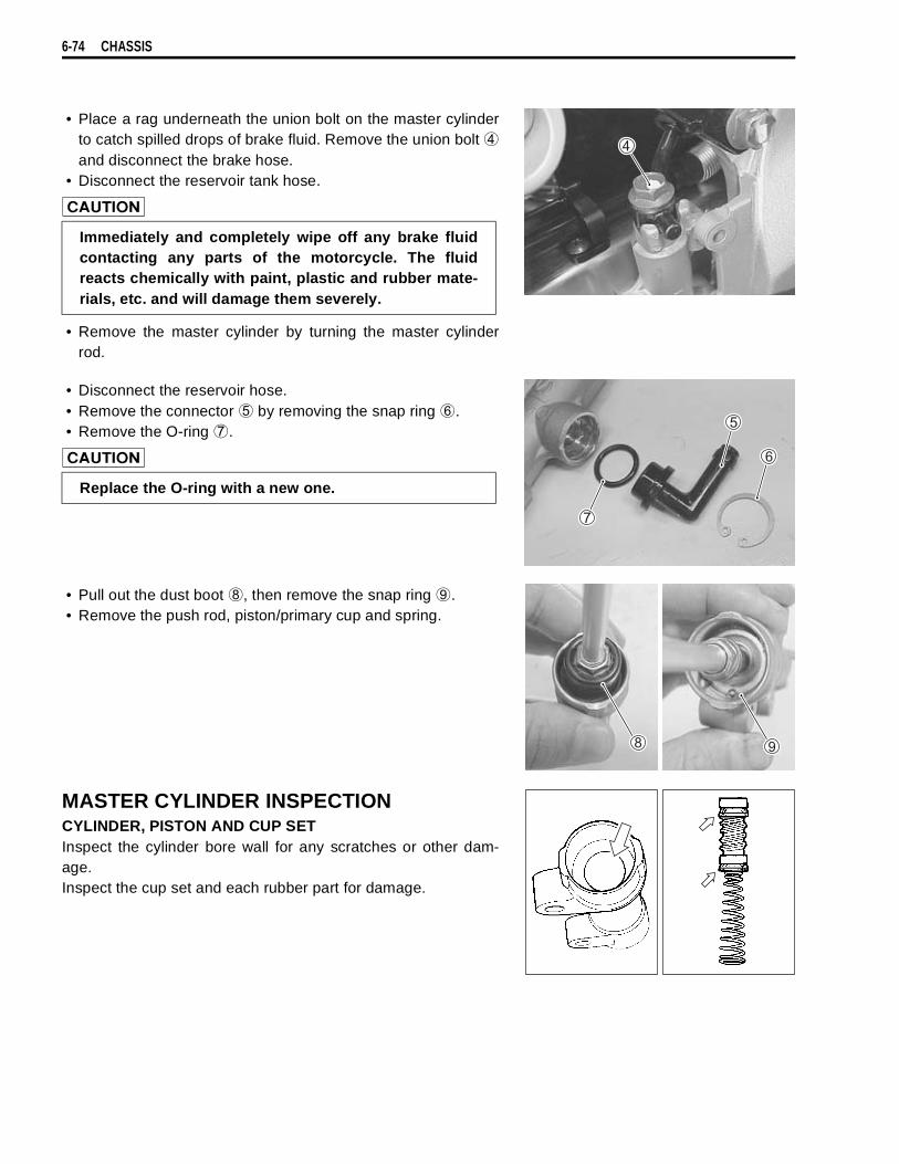
6-74 CHASSIS
• Place a rag underneath the union bolt on the master cylinderto catch spilled drops of brake fluid. Remove the union bolt
and disconnect the brake hose.• Disconnect the reservoir tank hose.
• Remove the master cylinder by turning the master cylinderrod.
• Disconnect the reservoir hose.• Remove the connector
by removing the snap ring
.• Remove the O-ring
.
• Pull out the dust boot
, then remove the snap ring
.• Remove the push rod, piston/primary cup and spring.
MASTER CYLINDER INSPECTIONCYLINDER, PISTON AND CUP SETInspect the cylinder bore wall for any scratches or other dam-age.Inspect the cup set and each rubber part for damage.
Immediately and completely wipe off any brake fluidcontacting any parts of the motorcycle. The fluidreacts chemically with paint, plastic and rubber mate-rials, etc. and will damage them severely.
Replace the O-ring with a new one.

CHASSIS 6-75
MASTER CYLINDER REASSEMBLY AND REMOUNTINGReassemble and remount the master cylinder in the reverseorder of removal and disassembly. Pay attention to the followingpoints:
Specification and Classification: DOT 4
• Apply brake fluid to the piston/cup set.• Install the following parts.
Spring
Piston/primary cup
Push rod
Snap ring
Dust boot• Apply the SUZUKI MOLY PASTE to the push rod.
99000-25140: SUZUKI MOLY PASTE
• Install the O-ring
, connector
and snap ring
to themaster cylinder.
• Install the master cylinder.• Tighten the lock nut
.
Rear master cylinder rod lock nut:18 N·m (1.8 kgf-m, 13.0 lb-ft)
* Wash the master cylinder components with freshbrake fluid before reassembly. Never use cleaningsolvent or gasoline to wash them.
* Do not wipe the components with a rag.* Apply brake fluid to the cylinder bore and all the
component to be inserted into the bore.
Replace the removed O-ring with a new one.

6-76 CHASSIS
• Install the reservoir tank and reservoir tank hose. (Rear brakehose routing: 8-25)
• Temporarily install the master cylinder to the frame.
• Connect the brake hose to the master cylinder. (Rear brakehose routing: 8-25)
• Tighten the brake hose union bolt to the specified torque.
Brake hose union bolt: 23 N·m (2.3 kgf-m, 16.5 lb-ft)
• Adjust the brake pedal height. ( 2-23)
• Reinstall the master cylinder.• Tighten the master cylinder mounting bolts to the specified
torque.
Rear master cylinder mounting bolt: 10 N·m (1.0 kgf-m, 7.0 lb-ft)
* The seal washers should be replaced with the newones to prevent fluid leakage.
* Bleed air from the system after reassembling themaster cylinder. ( 2-24)
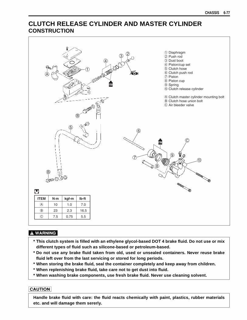
CHASSIS 6-77
CLUTCH RELEASE CYLINDER AND MASTER CYLINDERCONSTRUCTION
* This clutch system is filled with an ethylene glycol-based DOT 4 brake fluid. Do not use or mixdifferent types of fluid such as silicone-based or petroleum-based.
* Do not use any brake fluid taken from old, used or unsealed containers. Never reuse brakefluid left over from the last servicing or stored for long periods.
* When storing the brake fluid, seal the container completely and keep away from children.* When replenishing brake fluid, take care not to get dust into fluid.* When washing brake components, use fresh brake fluid. Never use cleaning solvent.
Handle brake fluid with care: the fluid reacts chemically with paint, plastics, rubber materialsetc. and will damage them sererly.
ITEM N·m kgf-m lb-ft
10 1.0 7.0
23 2.3 16.5
7.5 0.75 5.5
Diaphragm Push rod Dust boot Piston/cup set Clutch hose Clutch push rod Piston Piston cup Spring Clutch release cylinder
Clutch master cylinder mounting bolt Clutch hose union bolt Air bleeder valve
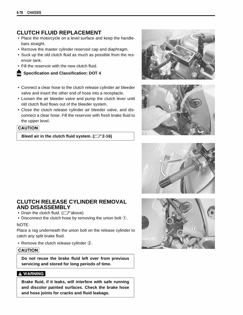
6-78 CHASSIS
CLUTCH FLUID REPLACEMENT• Place the motorcycle on a level surface and keep the handle-
bars straight.• Remove the master cylinder reservoir cap and diaphragm.• Suck up the old clutch fluid as much as possible from the res-
ervoir tank.• Fill the reservoir with the new clutch fluid.
Specification and Classification: DOT 4
• Connect a clear hose to the clutch release cylinder air bleedervalve and insert the other end of hose into a receptacle.
• Loosen the air bleeder valve and pump the clutch lever untilold clutch fluid flows out of the bleeder system.
• Close the clutch release cylinder air bleeder valve, and dis-connect a clear hose. Fill the reservoir with fresh brake fluid tothe upper level.
CLUTCH RELEASE CYLINDER REMOVAL AND DISASSEMBLY• Drain the clutch fluid. ( above)• Disconnect the clutch hose by removing the union bolt
.
NOTE:Place a rag underneath the union bolt on the release cylinder tocatch any split brake fluid.
• Remove the clutch release cylinder
.
Bleed air in the clutch fluid system. ( 2-16)
Do not reuse the brake fluid left over from previousservicing and stored for long periods of time.
Brake fluid, if it leaks, will interfere with safe runningand discolor painted surfaces. Check the brake hoseand hose joints for cracks and fluid leakage.
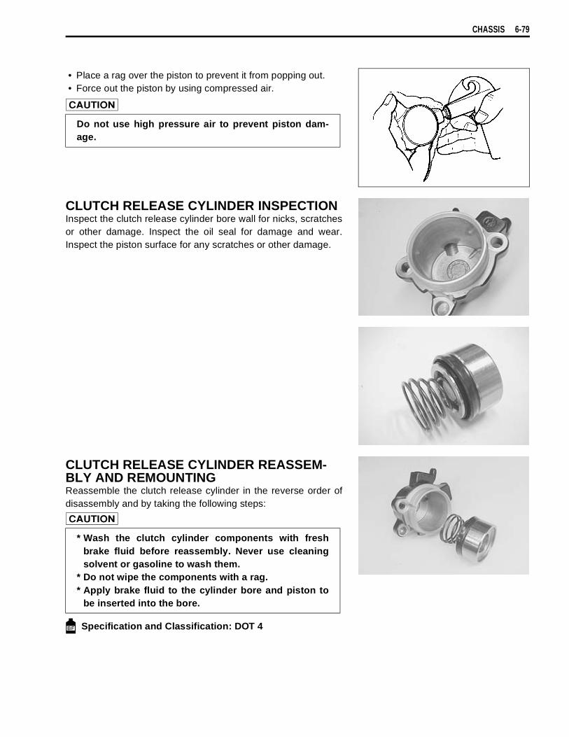
CHASSIS 6-79
• Place a rag over the piston to prevent it from popping out.• Force out the piston by using compressed air.
CLUTCH RELEASE CYLINDER INSPECTIONInspect the clutch release cylinder bore wall for nicks, scratchesor other damage. Inspect the oil seal for damage and wear.Inspect the piston surface for any scratches or other damage.
CLUTCH RELEASE CYLINDER REASSEM-BLY AND REMOUNTINGReassemble the clutch release cylinder in the reverse order ofdisassembly and by taking the following steps:
Specification and Classification: DOT 4
Do not use high pressure air to prevent piston dam-age.
* Wash the clutch cylinder components with freshbrake fluid before reassembly. Never use cleaningsolvent or gasoline to wash them.
* Do not wipe the components with a rag.* Apply brake fluid to the cylinder bore and piston to
be inserted into the bore.
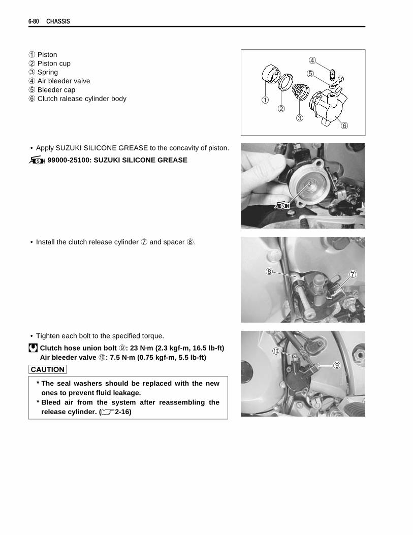
6-80 CHASSIS
Piston
Piston cup
Spring
Air bleeder valve
Bleeder cap
Clutch ralease cylinder body
• Apply SUZUKI SILICONE GREASE to the concavity of piston.
99000-25100: SUZUKI SILICONE GREASE
• Install the clutch release cylinder
and spacer
.
• Tighten each bolt to the specified torque.
Clutch hose union bolt
: 23 N·m (2.3 kgf-m, 16.5 lb-ft)Air bleeder valve
: 7.5 N·m (0.75 kgf-m, 5.5 lb-ft)
* The seal washers should be replaced with the newones to prevent fluid leakage.
* Bleed air from the system after reassembling therelease cylinder. ( 2-16)

CHASSIS 6-81
CLUTCH MASTER CYLINDER REMOVAL AND DISASSEMBLY• Remove the rear view mirror and clutch lever cover.• Drain the clutch fluid. ( 6-78)• Disconnect the clutch lever position switch lead wires.• Place a rag underneath the union bolt on the master cylinder
to catch spilled drops of brake fluid. Remove the union boltand disconnect the clutch hose from the master cylinder.
• Remove the clutch master cylinder.
• Remove the clutch lever
and clutch lever position switch
.
• Remove the boot
and push rod
.• Remove the snap ring
.
• Remove the piston/cup set
Secondary cup
Piston
Primary cup
Spring
Completely wipe off any brake fluid adhering to anyparts of motorcycle. The fluid reacts chemically withpaint, plastics, rubber materials, etc. and will damagethem severely.

6-82 CHASSIS
CLUTCH MASTER CYLINDER INSPECTIONInspect the piston surface for any scratches or other damage.Inspect the primary cup, secondary cup and dust seal for wearor damage.
Inspect the master cylinder bore for any scratches or other dam-age.
CLUTCH MASTER CYLINDER REASSEMBLY AND REMOUNTING Reassemble the master cylinder in the reverse order of removaland disassembly. Pay attention to the following points:
Specification and Classification: DOT 4
• Apply brake fluid to the piston/cup set and install them to theclutch master cylinder.
Spring
Primary cup
Piston
Secondary cup
Stopper plate
Snap ring
Dust boot
Push rod
* Wash the master cylinder components with freshbrake fluid before reassembly. Never use cleaningsolvent or gasoline to wash them.
* Do not wipe the components with a rag.Apply brake fluid to the cylinder bore and all the com-ponent to be inserted into the bore.
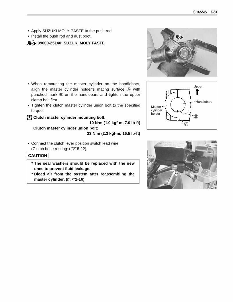
CHASSIS 6-83
• Apply SUZUKI MOLY PASTE to the push rod.• Install the push rod and dust boot.
99000-25140: SUZUKI MOLY PASTE
• When remounting the master cylinder on the handlebars,align the master cylinder holder’s mating surface
withpunched mark
on the handlebars and tighten the upperclamp bolt first.
• Tighten the clutch master cylinder union bolt to the specifiedtorque.
Clutch master cylinder mounting bolt:10 N·m (1.0 kgf-m, 7.0 lb-ft)
Clutch master cylinder union bolt:23 N·m (2.3 kgf-m, 16.5 lb-ft)
• Connect the clutch lever position switch lead wire.(Clutch hose routing: 8-22)
Mastercylinderholder
Upper
Handlebars
* The seal washers should be replaced with the newones to prevent fluid leakage.
* Bleed air from the system after reassembling themaster cylinder. ( 2-16)
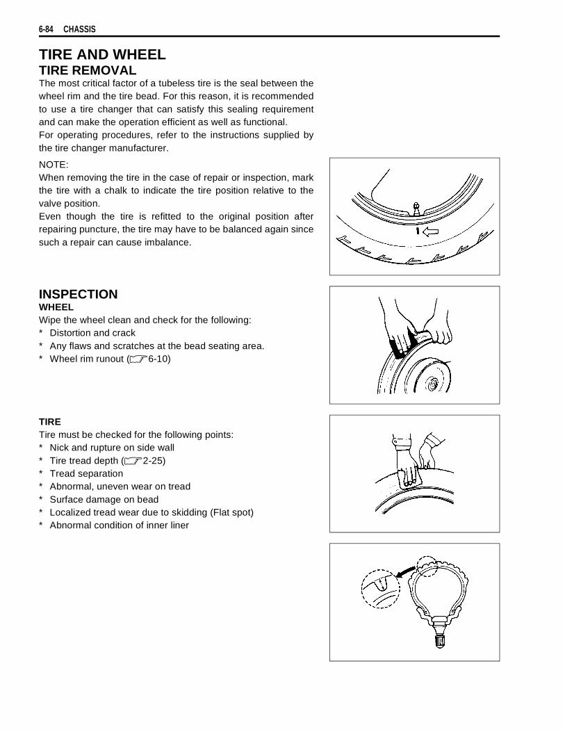
6-84 CHASSIS
TIRE AND WHEELTIRE REMOVALThe most critical factor of a tubeless tire is the seal between thewheel rim and the tire bead. For this reason, it is recommendedto use a tire changer that can satisfy this sealing requirementand can make the operation efficient as well as functional.For operating procedures, refer to the instructions supplied bythe tire changer manufacturer.
NOTE:When removing the tire in the case of repair or inspection, markthe tire with a chalk to indicate the tire position relative to thevalve position.Even though the tire is refitted to the original position afterrepairing puncture, the tire may have to be balanced again sincesuch a repair can cause imbalance.
INSPECTIONWHEELWipe the wheel clean and check for the following:* Distortion and crack* Any flaws and scratches at the bead seating area.* Wheel rim runout ( 6-10)
TIRETire must be checked for the following points:* Nick and rupture on side wall* Tire tread depth ( 2-25)* Tread separation* Abnormal, uneven wear on tread* Surface damage on bead* Localized tread wear due to skidding (Flat spot)* Abnormal condition of inner liner

CHASSIS 6-85
VALVE• Inspect the valve after the tire is removed from the rim.
Replace the valve with a new one if the seal rubber is peelingor has damage.
• Inspect the valve core. If the seal has abnormal deformation,replace the valve with a new one.
VALVE INSTALLATION• Any dust or rust around the valve hole must be cleaned off.
Then install the valve in the rim.
NOTE:To properly install the valve into the valve hole, apply a specialtire lubricant or neutral soapy liquid to the valve.
TIRE INSTALLATION• Apply tire lubricant to the tire bead.• When installing the tire onto the wheel, observe the following
points.
Seal
Be careful not to damage the lip of valve.
Valve hole
Wheel
Valve lip Valve
* Do not reuse the valve which has been onceremoved.
* Do not use oil, grease or gasoline on the tire bead inplace of tire lubricant.

6-86 CHASSIS
• When installing the tire, the arrow
on the side wall shouldpoint to the direction of wheel rotation.
• Align the chalk mark put on the tire at the time of removal withthe valve position.
• For installation procedure of tire onto the wheel, follow theinstructions given by the tire changer manufacturer.
• Bounce the tire several times while rotating. This makes thetire bead expand outward to contact the wheel, thereby facili-tating air inflation.
• Inflate the tire.
• In this condition, check the “rim line” cast on the tire sidewalls. The line must be equidistant from the wheel rim allaround. If the distance between the rim line and wheel rimvaries, this indicates that the bead is not properly seated. Ifthis is the case, deflate the tire completely and unseat thebead for both sides. Coat the bead with lubricant and fit thetire again.
• When the bead has been fitted properly, adjust the pressureto specification.
• As necessary, adjust the tire balance.
Tire pressureSolo riding: Front: 250 kPa (2.50 kgf/cm2, 36 psi)
Rear: 250 kPa (2.50 kgf/cm2, 36 psi)Dual riding: Front: 250 kPa (2.50 kgf/cm2, 36 psi)
Rear: 280 kPa (2.80 kgf/cm2, 41 psi)
* Do not inflate the tire to more than 400 kPa (4.0kgf/cm2). If inflated beyond this limit, the tire can burstand possibly cause injury. Do not stand directly overthe tire while inflating.
* In the case of preset pressure air inflator, pay specialcare for the set pressure adjustment.
Do not run with a repaired tire at a high speed.
Rim line

7
ELECTRICAL SYSTEM 7-1
CONTENTS
ELECTRICAL SYSTEM
CAUTIONS IN SERVICING ................................................................7- 2CONNECTOR ...............................................................................7- 2COUPLER ....................................................................................7- 2CLAMP .........................................................................................7- 2FUSE ............................................................................................7- 2SEMI-CONDUCTOR EQUIPPED PART ......................................7- 2BATTERY .....................................................................................7- 3CONNECTING THE BATTERY ...................................................7- 3WIRING PROCEDURE ................................................................7- 3USING THE MULTI CIRCUIT TESTER .......................................7- 3
LOCATION OF ELECTRICAL COMPONENTS .................................7- 4CHARGING SYSTEM .........................................................................7- 6
TROUBLESHOOTING .................................................................7- 6INSPECTION ................................................................................7- 7
STARTER SYSTEM AND SIDE-STAND/IGNITION INTERLOCK SYSTEM ..............................................................................................7-10
TROUBLE SHOOTING ................................................................7-10STARTER MOTOR REMOVAL AND DISASSEMBLY ................7-11STARTER MOTOR INSPECTION ...............................................7-12STARTER MOTOR REASSEMBLY ............................................7-12STARTER RELAY INSPECTION .................................................7-13SIDE-STAND/IGNITION INTERLOCK SYSTEM PARTS INSPECTION ................................................................................7-14
IGNITION SYSTEM .............................................................................7-17TROUBLESHOOTING .................................................................7-17INSPECTION ................................................................................7-19
COMBINATION METER .....................................................................7-22REMOVAL AND DISASSEMBLY ................................................7-22INSPECTION ................................................................................7-23ENGINE COOLANT TEMPERATURE METER AND INDICATOR ..................................................................................7-25
LAMPS ................................................................................................7-29HEADLIGHT, BRAKE LIGHT/TAILLIGHT AND TURN SIGNAL LIGHT ............................................................................7-29
RELAYS ..............................................................................................7-30TURN SIGNAL/SIDE-STAND RELAY .........................................7-30STARTER RELAY ........................................................................7-30FUEL PUMP RELAY ....................................................................7-30SWITCHES ...................................................................................7-31
BATTERY ............................................................................................7-33SPECIFICATIONS ........................................................................7-33INITIAL CHARGING .....................................................................7-33SERVICING ..................................................................................7-35RECHARGING OPERATION .......................................................7-35
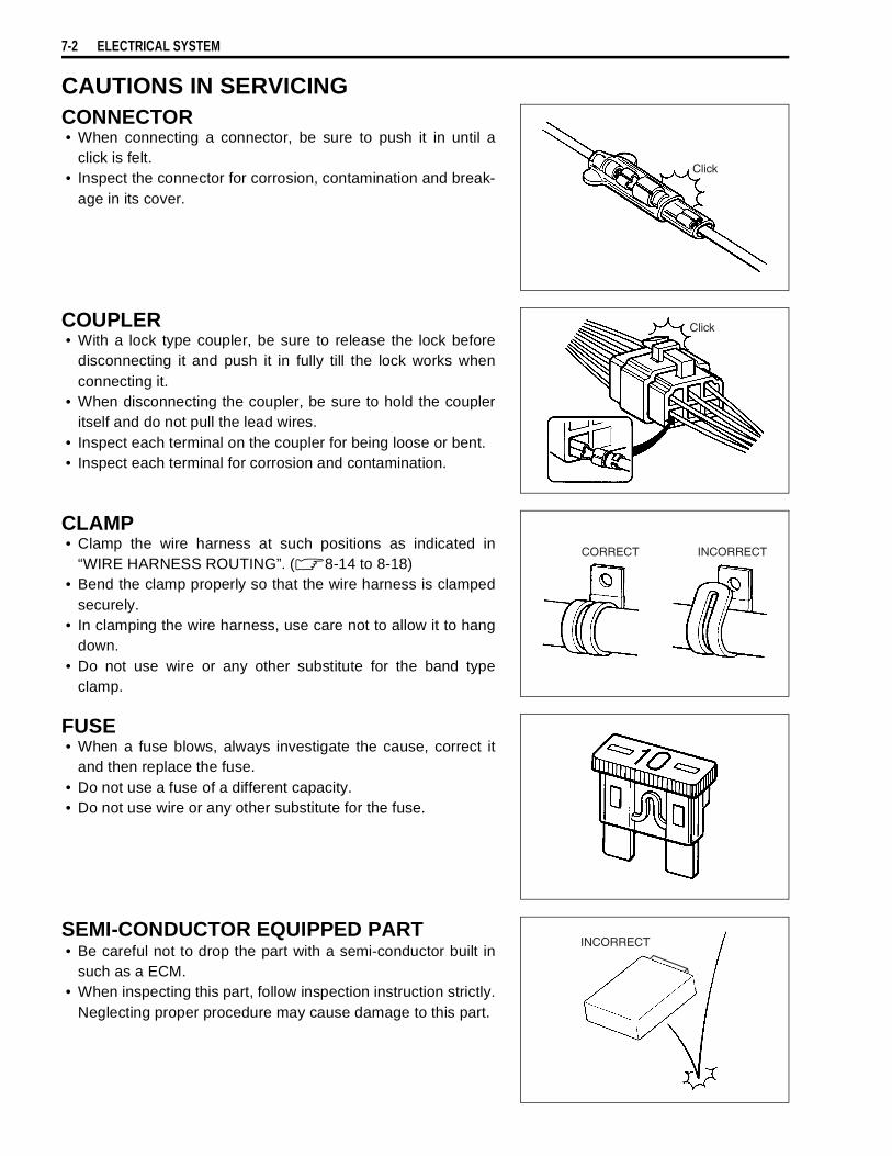
7-2 ELECTRICAL SYSTEM
CAUTIONS IN SERVICINGCONNECTOR• When connecting a connector, be sure to push it in until a
click is felt.• Inspect the connector for corrosion, contamination and break-
age in its cover.
COUPLER• With a lock type coupler, be sure to release the lock before
disconnecting it and push it in fully till the lock works whenconnecting it.
• When disconnecting the coupler, be sure to hold the coupleritself and do not pull the lead wires.
• Inspect each terminal on the coupler for being loose or bent.• Inspect each terminal for corrosion and contamination.
CLAMP• Clamp the wire harness at such positions as indicated in
“WIRE HARNESS ROUTING”. ( 8-14 to 8-18)• Bend the clamp properly so that the wire harness is clamped
securely.• In clamping the wire harness, use care not to allow it to hang
down.• Do not use wire or any other substitute for the band type
clamp.
FUSE• When a fuse blows, always investigate the cause, correct it
and then replace the fuse.• Do not use a fuse of a different capacity.• Do not use wire or any other substitute for the fuse.
SEMI-CONDUCTOR EQUIPPED PART• Be careful not to drop the part with a semi-conductor built in
such as a ECM.• When inspecting this part, follow inspection instruction strictly.
Neglecting proper procedure may cause damage to this part.

ELECTRICAL SYSTEM 7-3
BATTERY• The MF battery used in this motorcycle does not require main-
tenance (e.g., electrolyte level inspection, distilled waterreplenishment).
• During normal charging, no hydrogen gas is produced. How-ever, if the battery is overcharged, hydrogen gas may be pro-duced. Therefore, be sure there are no fire or spark sources(e.g., short circuit) nearby when charging the battery.
• Be sure to recharge the battery in a well-ventilated and openarea.
• Note that the charging system for the MF battery is differentfrom that of a conventional battery. Do not replace the MFbattery with a conventional battery.
CONNECTING THE BATTERY• When disconnecting terminals from the battery for disassem-
bly or servicing, be sure to disconnect the
battery leadwire, first.
• When connecting the battery lead wires, be sure to connectthe
battery lead wire, first.• If the terminal is corroded, remove the battery, pour warm
water over it and clean it with a wire brush.• After connecting the battery, apply a light coat of grease to the
battery terminals.• Install the cover over the
battery terminal.
WIRING PROCEDURE• Properly route the wire harness according to the “WIRE
ROUTING” section. ( 8-14 to 8-18)
USING THE MULTI CIRCUIT TESTER• Properly use the multi circuit tester
and
probes.Improper use can cause damage to the motorcycle andtester.
• If the voltage and current values are not known, begin mea-suring in the highest range.
• When measuring the resistance, make sure that no voltage isapplied. If voltage is applied, the tester will be damaged.
• After using the tester, be sure to turn the switch to the OFFposition.
Before using the multi circuit tester, read its instructionmanual.

7-4 ELECTRICAL SYSTEM
LOCATION OF ELECTRICAL COMPONENTS
BatteryFuse box Side-stand/turn signal relayStarter relayFuel pump relayTip over sensor (4-42)AP sensor (4-40)ECM (Engine Control Module)Ignition coil (No.2)Regulator/rectifier
Fuel injector (4-47 and 4-70)STP sensor (4-44)TP sensor (4-36)Secondary throttle valve actuator (4-43)GeneratorSpeedometer sensorCKP sensorSide stand switchMode selection switch coupler
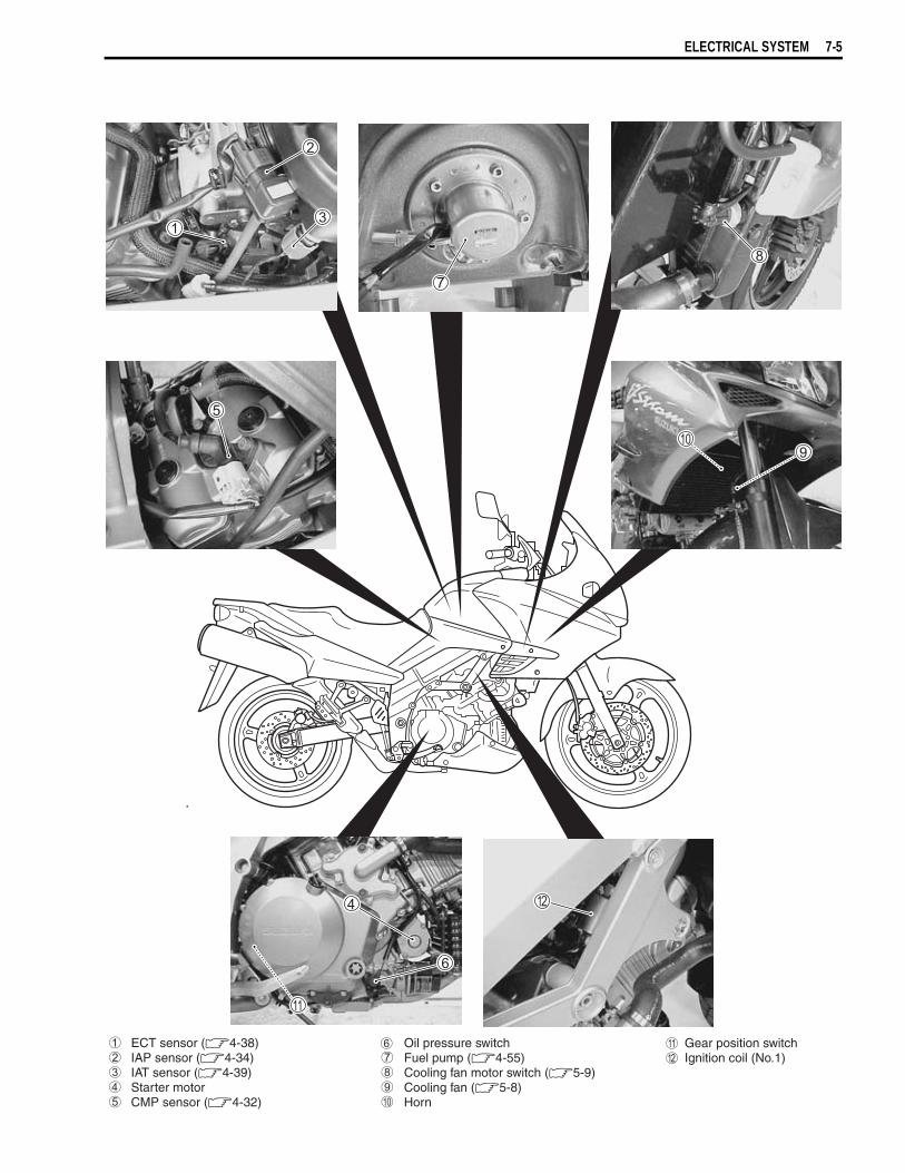
ELECTRICAL SYSTEM 7-5
ECT sensor (4-38)IAP sensor (4-34)IAT sensor (4-39)Starter motorCMP sensor (4-32)
Oil pressure switchFuel pump (4-55)Cooling fan motor switch (5-9)Cooling fan (5-8)Horn
Gear position switchIgnition coil (No.1)
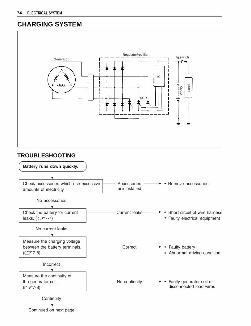
7-6 ELECTRICAL SYSTEM
CHARGING SYSTEM
TROUBLESHOOTING
GeneratorRegulator/rectifier
SCR
IC
Ig.switch
Load
Bat
tery
Battery runs down quickly.
Check accessories which use excessive Accessories • Remove accessories.amounts of electricity. are installed
No accessories
Check the battery for current Current leaks Short circuit of wire harnessleaks. ( 7-7) Faulty electrical equipment
No current leaks
Measure the charging voltagebetween the battery terminals. Correct Faulty battery( 7-8) Abnormal driving condition
Incorrect
Measure the continuity ofthe generator coil. No continuity Faulty generator coil or( 7-8) disconnected lead wires
Continuity
Continued on next page
••
••
•
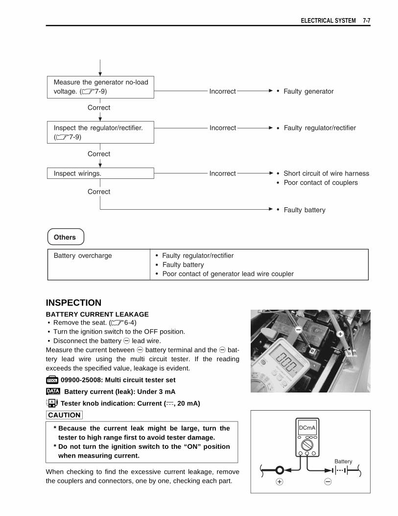
ELECTRICAL SYSTEM 7-7
INSPECTIONBATTERY CURRENT LEAKAGE• Remove the seat. ( 6-4)• Turn the ignition switch to the OFF position.• Disconnect the battery
lead wire.Measure the current between
battery terminal and the
bat-tery lead wire using the multi circuit tester. If the readingexceeds the specified value, leakage is evident.
09900-25008: Multi circuit tester set
Battery current (leak): Under 3 mA
Tester knob indication: Current ( , 20 mA)
When checking to find the excessive current leakage, removethe couplers and connectors, one by one, checking each part.
* Because the current leak might be large, turn thetester to high range first to avoid tester damage.
* Do not turn the ignition switch to the “ON” positionwhen measuring current.
Measure the generator no-loadvoltage. ( 7-9) Incorrect Faulty generator
Correct
Inspect the regulator/rectifier. Incorrect Faulty regulator/rectifier( 7-9)
Correct
Inspect wirings. Incorrect Short circuit of wire harness Poor contact of couplers
Correct
Faulty battery
Others
Battery overcharge Faulty regulator/rectifier Faulty battery Poor contact of generator lead wire coupler
•
•
•
•
•••
•
Battery
DCmA
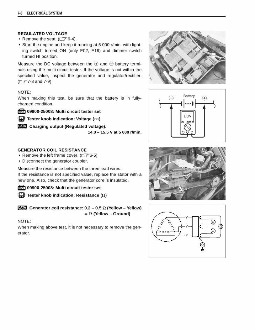
7-8 ELECTRICAL SYSTEM
REGULATED VOLTAGE• Remove the seat. ( 6-4).• Start the engine and keep it running at 5 000 r/min. with light-
ing switch turned ON (only E02, E19) and dimmer switchturned HI position.
Measure the DC voltage between the
and
battery termi-nals using the multi circuit tester. If the voltage is not within thespecified value, inspect the generator and regulator/rectifier.( 7-8 and 7-9)
NOTE:When making this test, be sure that the battery is in fully-charged condition.
09900-25008: Multi circuit tester set
Tester knob indication: Voltage ( )
Charging output (Regulated voltage):14.0 – 15.5 V at 5 000 r/min.
GENERATOR COIL RESISTANCE• Remove the left frame cover. ( 6-5)• Disconnect the generator coupler.
Measure the resistance between the three lead wires.If the resistance is not specified value, replace the stator with anew one. Also, check that the generator core is insulated.
09900-25008: Multi circuit tester set
Tester knob indication: Resistance (Ω)
Generator coil resistance: 0.2 – 0.5 Ω (Yellow – Yellow)∞ Ω (Yellow – Ground)
NOTE:When making above test, it is not necessary to remove the gen-erator.
Battery
DCV
Y
Y
Y
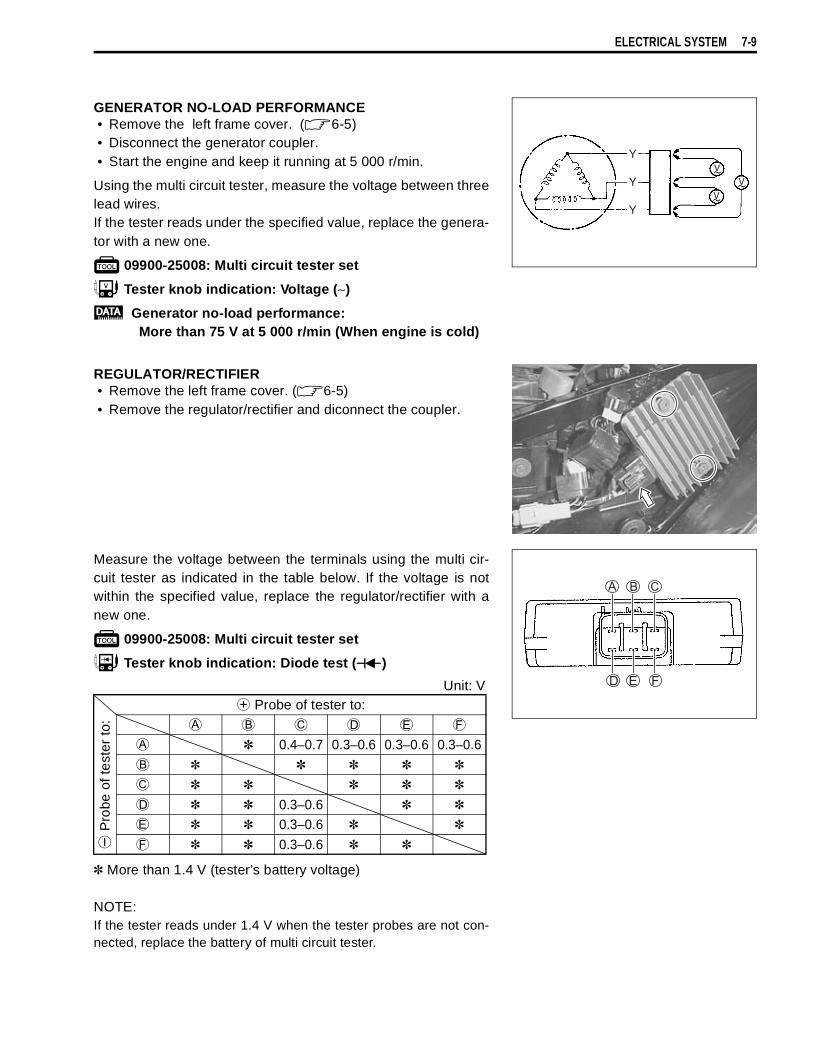
ELECTRICAL SYSTEM 7-9
GENERATOR NO-LOAD PERFORMANCE• Remove the left frame cover. ( 6-5)• Disconnect the generator coupler.• Start the engine and keep it running at 5 000 r/min.
Using the multi circuit tester, measure the voltage between threelead wires.If the tester reads under the specified value, replace the genera-tor with a new one.
09900-25008: Multi circuit tester set
Tester knob indication: Voltage (∼)
Generator no-load performance:More than 75 V at 5 000 r/min (When engine is cold)
REGULATOR/RECTIFIER• Remove the left frame cover. ( 6-5)• Remove the regulator/rectifier and diconnect the coupler.
Measure the voltage between the terminals using the multi cir-cuit tester as indicated in the table below. If the voltage is notwithin the specified value, replace the regulator/rectifier with anew one.
09900-25008: Multi circuit tester set
Tester knob indication: Diode test ( )
More than 1.4 V (tester’s battery voltage)
NOTE:If the tester reads under 1.4 V when the tester probes are not con-nected, replace the battery of multi circuit tester.
Y
Y
Y
Unit: V
Probe of tester to:
Pro
be o
f te
ster
to:
0.4–0.7 0.3–0.6 0.3–0.6 0.3–0.6
0.3–0.6
0.3–0.6
0.3–0.6
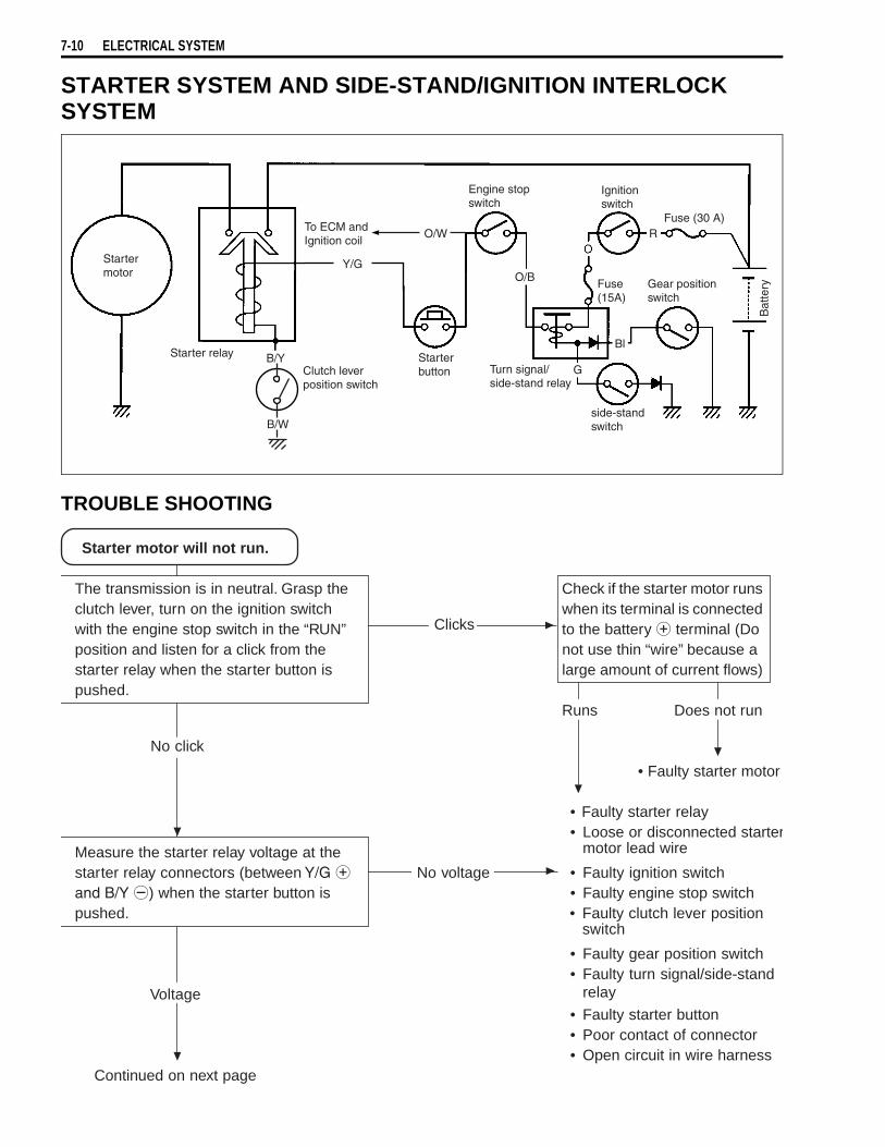
7-10 ELECTRICAL SYSTEM
STARTER SYSTEM AND SIDE-STAND/IGNITION INTERLOCK SYSTEM
TROUBLE SHOOTING
Startermotor
Starter relay B/Y
To ECM andIgnition coil
O/W
Y/G
Clutch leverposition switch
B/W
Starterbutton
Engine stopswitch
O/B
Turn signal/side-stand relay
G
Ignitionswitch
RFuse (30 A)
Gear positionswitch
Fuse(15A)
Bat
tery
Bl
side-standswitch
Starter motor will not run.
The transmission is in neutral. Grasp the Check if the starter motor runsclutch lever, turn on the ignition switch when its terminal is connectedwith the engine stop switch in the “RUN” Clicks to the battery terminal (Doposition and listen for a click from the not use thin “wire” because astarter relay when the starter button is large amount of current flows)pushed.
Runs Does not run
No click
• Faulty starter motor
Measure the starter relay voltage at thestarter relay connectors (between No voltage
) when the starter button ispushed.
Voltage
Continued on next page
• Faulty starter relay• Loose or disconnected starter
motor lead wire
• Faulty ignition switch• Faulty engine stop switch• Faulty clutch lever position
switch
• Faulty gear position switch• Faulty turn signal/side-stand
relay
• Faulty starter button• Poor contact of connector• Open circuit in wire harness

ELECTRICAL SYSTEM 7-11
STARTER MOTOR REMOVAL AND DISASSEMBLY• Remove the engine under cover.• Remove the starter motor and disconnect the starter motor
lead wire
.
• Disassemble the starter motor as shown in the illustration.
Check the starter relay.(7-13)
Incorrect
Correct
The starter motor runs when the transmission is in neutral with the side-stand up or down, but does notrun when the transmission is in any position other than neutral with the side-stand down.
Check the side-stand switch.(7-14)
Incorrect
Correct
Others
Engine does not turn thoughthe starter motor runs.
• Faulty starter relay
• Poor contact of thestarter relay
• Faulty side-stand switch
• Open circuit in wire harness
• Faulty starter torque limiter (3-64)
• Poor contact of connector
O-ring Housing Armature Washer O-ring Starter motor case Starter brush holder assembly O-ring
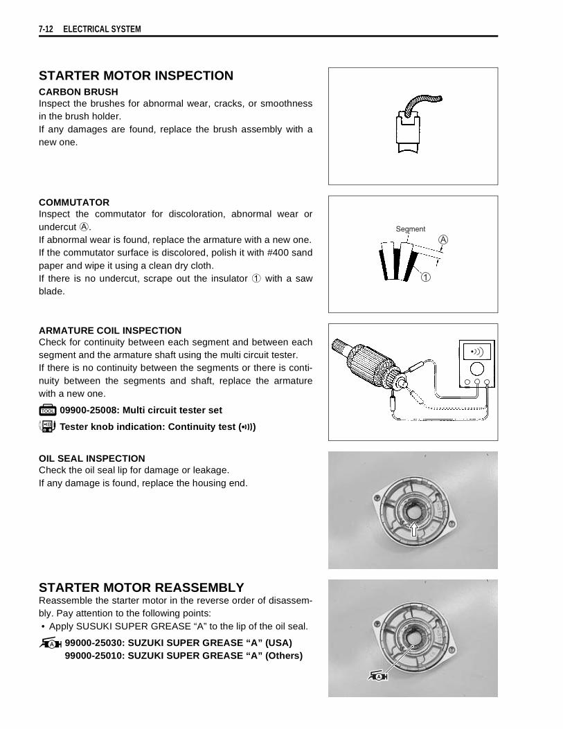
7-12 ELECTRICAL SYSTEM
STARTER MOTOR INSPECTIONCARBON BRUSHInspect the brushes for abnormal wear, cracks, or smoothnessin the brush holder.If any damages are found, replace the brush assembly with anew one.
COMMUTATORInspect the commutator for discoloration, abnormal wear orundercut
.If abnormal wear is found, replace the armature with a new one.If the commutator surface is discolored, polish it with #400 sandpaper and wipe it using a clean dry cloth.If there is no undercut, scrape out the insulator
with a sawblade.
ARMATURE COIL INSPECTIONCheck for continuity between each segment and between eachsegment and the armature shaft using the multi circuit tester.If there is no continuity between the segments or there is conti-nuity between the segments and shaft, replace the armaturewith a new one.
09900-25008: Multi circuit tester set
Tester knob indication: Continuity test ( )
OIL SEAL INSPECTIONCheck the oil seal lip for damage or leakage.If any damage is found, replace the housing end.
STARTER MOTOR REASSEMBLYReassemble the starter motor in the reverse order of disassem-bly. Pay attention to the following points:• Apply SUSUKI SUPER GREASE “A” to the lip of the oil seal.
99000-25030: SUZUKI SUPER GREASE “A” (USA)99000-25010: SUZUKI SUPER GREASE “A” (Others)

ELECTRICAL SYSTEM 7-13
• Apply a small quantity of SUZUKI MOLY PASTE to the arma-ture shaft.
99000-25140: SUZUKI MOLY PASTE
• Apply a small quantity of THREAD LOCK “1342” to the startermotor housing bolts.
99000-32050: THREAD LOCK “1342”
• Apply SUZUKI SUPER GREASE “A” to the O-ring.
99000-25030: SUZUKI SUPER GREASE “A” (USA)99000-25010: SUZUKI SUPER GREASE “A” (Others)
• Tighten the starter motor lead wire nut to the specified torque.
Starter motor lend wire nut: 5 N·m (0.5 Kgf-m, 3.7 lb-ft)
STARTER RELAY INSPECTION• Remove the seat. ( 6-4)• Disconnect the battery
lead wire from the battery.• Remove the starter relay cover
.• Disconnect the starter relay coupler
.
• Disconnect the starter motor lead wire
, battery lead wire
.• Remove the starter relay
.

7-14 ELECTRICAL SYSTEM
Apply 12 V to
and
terminals and check for continuitybetween the positive and negative terminals using the multi cir-cuit tester. If the starter relay clicks and continuity is found, therelay is ok.
09900-25008: Multi circuit tester set
Tester knob indication: Continuity test ( )
Measure the relay coil resistance between the terminals usingthe multi circuit tester. If the resistance is not within the specifiedvalue, replace the starter relay with a new one.
09900-25008: Multi circuit tester set
Tester knob indication: Resistance (Ω)
Starter relay resistance: 3 – 6 Ω
SIDE-STAND/IGNITION INTERLOCK SYSTEM PARTS INSPECTIONCheck the interlock system for proper operation. If the interlocksystem does not operate properly, check each component fordamage or abnormalities. If any abnormality is found, replacethe component with a new one.
SIDE-STAND SWITCH• Remove the seat. ( 6-4)• Remove the left frame cover. ( 6-5)• Disconnect the side-stand switch coupler and measure the
voltage between Green and Black/White lead wires.
09900-25008: Multi circuit tester set
Tester knob indication: Diode test ( )
NOTE:If the tester reads under 1.4 V when the tester probes are notconnected, replace its battery.
Do not apply a battery voltage to the starter relay formore than five seconds, since the relay coil may over-heat and damaged.
Up
Down
ON(Side-stand up)
OFF(Side-stand down)
Green( Probe)
Black/White( Probe)
0.4 – 0.6 V
More than 1.4 V(Tester’s battery voltage)

ELECTRICAL SYSTEM 7-15
GEAR POSITION SWITCH• Remove the seat. ( 6-4)• Remove the fuel tank front cover.• Remove the fuel tank side covers.• Lift and support the fuel tank with the fuel tank prop stay.
( 4-51)• Disconnect the gear position swtich coupler and check the
continuity between Blue and Black with the transmission in“NEUTRAL”.
• Connect the gear position switch coupler to the wiring har-ness.
• Turn the ignition switch to “ON” position and side-stand toupright position.
Measure the voltage between Pink and Black lead wires usingthe multi circuit tester when shifting the gearshift lever from lowto top.
09900-25008: Multi circuit tester set
Tester knob indication: Voltage ( )
Gear position switch voltage: More than 0.6V
NOTE:* When connecting the multi circuit tester, use a fine copper wire
(O.D is below 0.5 mm) to the back side of the lead wire couplerand connect the probes of tester to them.
* Use a fine copper wire, the outer diameter being below 0.5mm, to prevent the rubber of the water proof coupler fromdamage.
TURN SIGNAL/SIDE-STAND RELAYThe turn signal/side-stand relay is composed of the turn signalrelay, and the side-stand relay and diode.• Remove the seat. ( 6-4)• Remove the turn signal/side-stand relay.
When disconnecting and connecting the gear positionswitch coupler, make sure to turn OFF the ignitionswitch, or electronic parts may get damaged.
ON (Neutral)
OFF (Expect neutral)
Blue Black
(* Low to top gear position* Except neutral position( (Pink – Black)
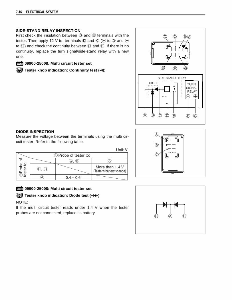
7-16 ELECTRICAL SYSTEM
SIDE-STAND RELAY INSPECTIONFirst check the insulation between
and
terminals with thetester. Then apply 12 V to terminals
and
(
to
and
to
) and check the continuity between
and
. If there is nocontinuity, replace the turn signal/side-stand relay with a newone.
09900-25008: Multi circuit tester set
Tester knob indication: Continuity test ( )
DIODE INSPECTIONMeasure the voltage between the terminals using the multi cir-cuit tester. Refer to the following table.
09900-25008: Multi circuit tester set
Tester knob indication: Diode test ( )
NOTE:If the multi circuit tester reads under 1.4 V when the testerprobes are not connected, replace its battery.
More than 1.4 V(Tester’s battery voltage)
0.4 – 0.6
Unit: V

ELECTRICAL SYSTEM 7-17
IGNITION SYSTEM
NOTE:The fuel cut-off circuit is incorporated in this ECM in order to prevent over-running of engine. When enginespeed reaches 9 500 r/min, this circuit cuts off fuel at the fuel injector. But under no load, the clutch lever ispulled or the gear position is neutral, this circuit cuts off fuel when engine speed reaches 9 000 r/min.
TROUBLESHOOTING
Under no load, the engine can run over 9 000 r/min, even if the fuel cut-off circuit is effective,and it may cause engine damage. Do not run the engine without load over 9 000 r/min at any-time.
ECM
Throttlepositionsensor
Enginecoolant temp.sensor
Gearpositionswitch
Engine stop switch
Side-standrelay
Fuse
Fuse
Ignitionswitch
Ignitioncoil
Spark plug
Battery
Wave formarrangementcircuit
Wave formarrangementcircuit
CPU
Power sourcecircuit
CKPsensor
Cam positionsensor
# 1
# 2
No spark or poor spark
Check the ignition system couplers for poor connections. Loose • Poor connection of couplers
Correct
Continued on next page
* Check that the transmission is in neutral and the engine stop switch is in the “RUN” position. Pullthe clutch lever. Check that the fuse is not blownand the battery is fully-charged before diagnosing.
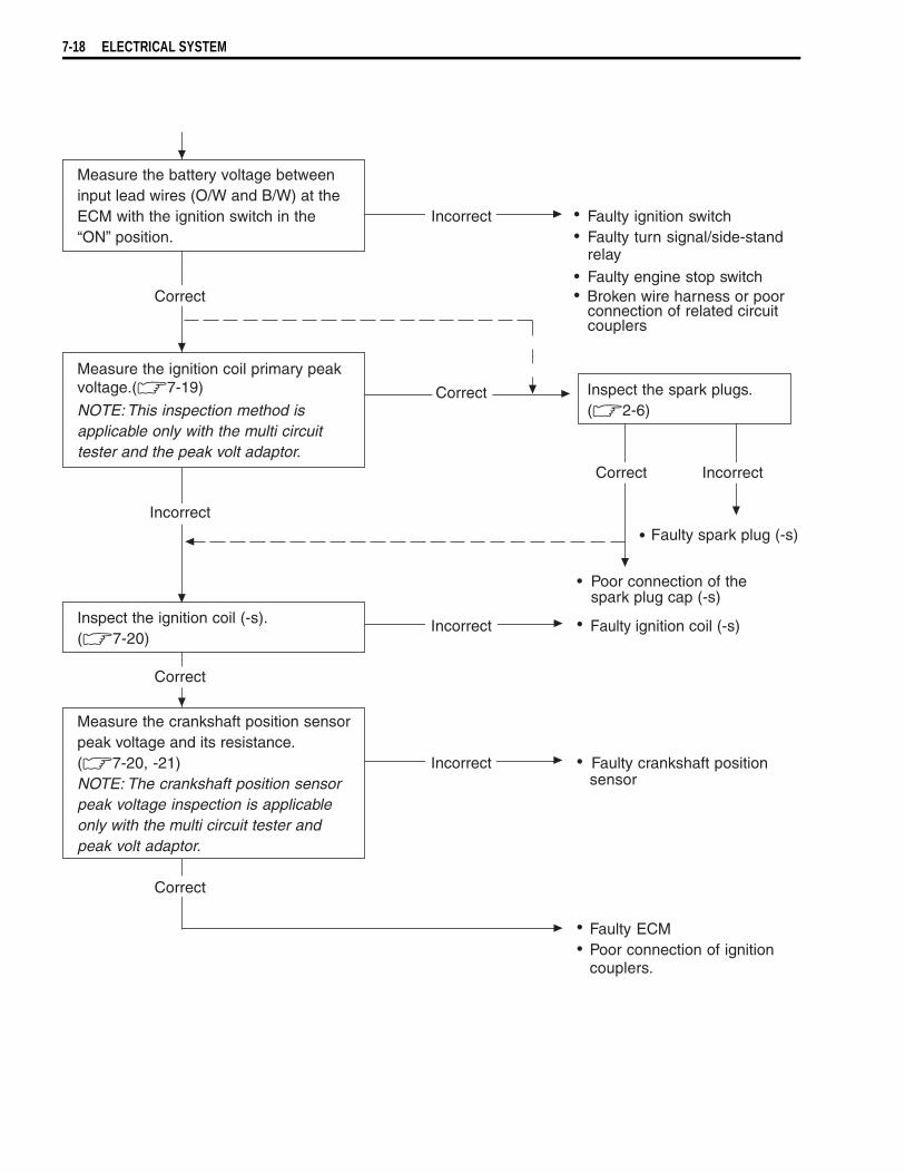
7-18 ELECTRICAL SYSTEM
Measure the battery voltage between input lead wires (O/W and B/W) at the ECM with the ignition switch in the “ON” position.
Incorrect Faulty ignition switch Faulty turn signal/side-standrelay
Faulty engine stop switchCorrect Broken wire harness or poor
connection of related circuitcouplers
Measure the ignition coil primary peak voltage.(7-19) Inspect the spark plugs.NOTE: This inspection method is
Correct(2-6)
applicable only with the multi circuittester and the peak volt adaptor.
Correct Incorrect
Incorrect Faulty spark plug (-s)
Poor connection of thespark plug cap (-s)
Inspect the ignition coil (-s).(7-20)
Incorrect Faulty ignition coil (-s)
Correct
Measure the crankshaft position sensorpeak voltage and its resistance.(7-20, -21) Incorrect Faulty crankshaft positionNOTE: The crankshaft position sensor sensor
peak voltage inspection is applicableonly with the multi circuit tester andpeak volt adaptor.
Correct
Faulty ECM Poor connection of ignitioncouplers.
••
••
•
•
••
•
•

ELECTRICAL SYSTEM 7-19
INSPECTIONIGNITION COIL PRIMARY PEAK VOLTAGE• Lift and support the fuel tank. ( 4-51)• Disconnect the two spark plug caps.• Connect new two spark plugs to each spark plug cap and
ground them.NOTE:Make sure that all couplers and spark plugs are connected prop-erly and the battery used is in fully-charged condition.
Measure the No.1 and No.2 ignition coils primary peak voltagein the following procedure.• Connect the multi circuit tester with peak voltage adaptor as
follows.
No.1 ignition coil:
Probe: Black terminal
Probe: Ground
No.2 ignition coil:
Probe: White/Blue terminal
Probe: GroundNOTE:Do not disconnect the ignition coil primary wire coupler.
09900-25008: Multi circuit tester set
• Shift the transmission into the neutral and then turn the igni-tion switch to the “ON” position.
• Pull the clutch lever.• Press the starter button and allow the engine to crank for a
few seconds, and then measure the ignition coil primary peakvoltage.
• Repeat the above procedure a few times and measure thehighest ignition coil primary peak voltage.
Tester knob indication: Voltage ( )Ignition coil primary peak voltage: More than 150 V
• If the peak voltage is lower than the specified values, inspectthe ignition coil. ( 7-20)
Avoid grounding the spark plugs and suppling theelectrical shock to the cylinder head cover (magne-sium parts) in order to prevent the magnesium mate-rial from damage.
Before using the multi circuit tester and peak voltadaptor, be sure to refer to the appropriate instructionmanual.
While testing, do not touch the tester probes andspark plugs to prevent receiving an electric shock.
ECM
Peak volt adaptor
B or W/Bl
Ignitioncoil
Newsparkplug
Battery
B/O
B
Ignition coil #1
W/Bl
O/W
Ignition coil #2
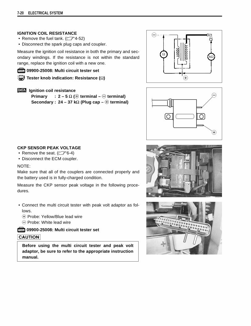
7-20 ELECTRICAL SYSTEM
IGNITION COIL RESISTANCE• Remove the fuel tank. ( 4-52)• Disconnect the spark plug caps and coupler.
Measure the ignition coil resistance in both the primary and sec-ondary windings. If the resistance is not within the standardrange, replace the ignition coil with a new one.
09900-25008: Multi circuit tester set
Tester knob indication: Resistance (Ω)
Ignition coil resistancePrimary : 2 – 5 Ω (
terminal –
terminal)Secondary : 24 – 37 kΩ (Plug cap –
terminal)
CKP SENSOR PEAK VOLTAGE• Remove the seat. ( 6-4)• Disconnect the ECM coupler.
NOTE:Make sure that all of the couplers are connected properly andthe battery used is in fully-charged condition.
Measure the CKP sensor peak voltage in the following proce-dures.
• Connect the multi circuit tester with peak volt adaptor as fol-lows.
Probe: Yellow/Blue lead wire
Probe: White lead wire
09900-25008: Multi circuit tester set
kΩΩ
Before using the multi circuit tester and peak voltadaptor, be sure to refer to the appropriate instructionmanual.
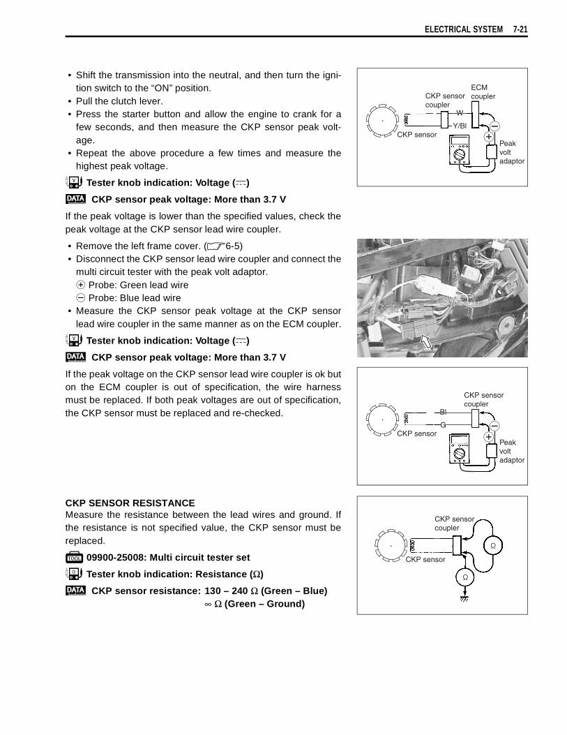
ELECTRICAL SYSTEM 7-21
• Shift the transmission into the neutral, and then turn the igni-tion switch to the “ON” position.
• Pull the clutch lever.• Press the starter button and allow the engine to crank for a
few seconds, and then measure the CKP sensor peak volt-age.
• Repeat the above procedure a few times and measure thehighest peak voltage.
Tester knob indication: Voltage ( )
CKP sensor peak voltage: More than 3.7 V
If the peak voltage is lower than the specified values, check thepeak voltage at the CKP sensor lead wire coupler.
• Remove the left frame cover. ( 6-5)• Disconnect the CKP sensor lead wire coupler and connect the
multi circuit tester with the peak volt adaptor.
Probe: Green lead wire
Probe: Blue lead wire• Measure the CKP sensor peak voltage at the CKP sensor
lead wire coupler in the same manner as on the ECM coupler.
Tester knob indication: Voltage ( )
CKP sensor peak voltage: More than 3.7 V
If the peak voltage on the CKP sensor lead wire coupler is ok buton the ECM coupler is out of specification, the wire harnessmust be replaced. If both peak voltages are out of specification,the CKP sensor must be replaced and re-checked.
CKP SENSOR RESISTANCEMeasure the resistance between the lead wires and ground. Ifthe resistance is not specified value, the CKP sensor must bereplaced.
09900-25008: Multi circuit tester set
Tester knob indication: Resistance (Ω)
CKP sensor resistance: 130 – 240 Ω (Green – Blue)∞ Ω (Green – Ground)
CKP sensor
CKP sensorcoupler
G/W
W
ECMcoupler
Peakvoltadaptor
W
Y/Bl
CKP sensorPeakvoltadaptor
CKP sensorcoupler
G
B
Bl
G
CKP sensor
CKP sensorcoupler

7-22 ELECTRICAL SYSTEM
COMBINATION METERREMOVAL AND DISASSEMBLY• Remove the combination meter panel. ( 6-6).• Remove the combination meter
.
• Disassemble the combination meter as follows.
When disconnecting and connecting the combinationmeter coupler, make sure to turn OFF the ignitionswitch, or electronic parts may get damaged.
Do not attempt to disassemble the combination meterunit.
Combination meter coverCombination meter unit
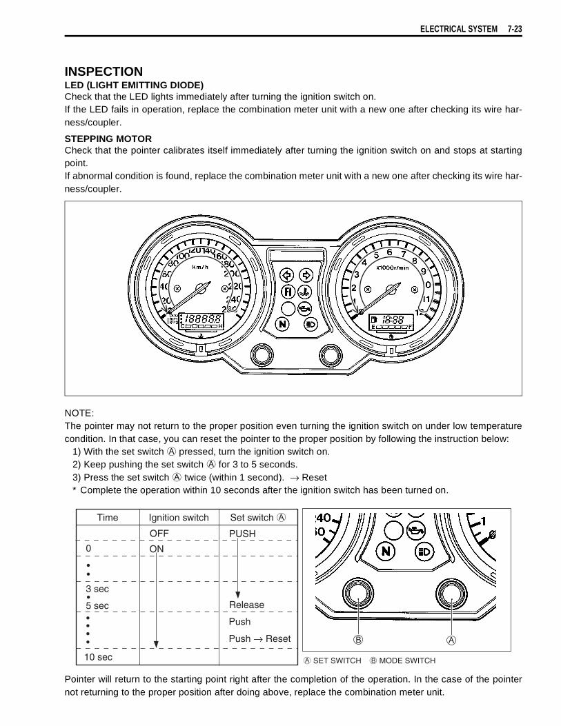
ELECTRICAL SYSTEM 7-23
INSPECTIONLED (LIGHT EMITTING DIODE)Check that the LED lights immediately after turning the ignition switch on.If the LED fails in operation, replace the combination meter unit with a new one after checking its wire har-ness/coupler.
STEPPING MOTORCheck that the pointer calibrates itself immediately after turning the ignition switch on and stops at startingpoint.If abnormal condition is found, replace the combination meter unit with a new one after checking its wire har-ness/coupler.
NOTE:The pointer may not return to the proper position even turning the ignition switch on under low temperaturecondition. In that case, you can reset the pointer to the proper position by following the instruction below:
1) With the set switch
pressed, turn the ignition switch on.2) Keep pushing the set switch
for 3 to 5 seconds.3) Press the set switch
twice (within 1 second). → Reset* Complete the operation within 10 seconds after the ignition switch has been turned on.
Pointer will return to the starting point right after the completion of the operation. In the case of the pointernot returning to the proper position after doing above, replace the combination meter unit.
SET SWITCH MODE SWITCH
Time Ignition switch Set switch
OFF
ON0
••
3 sec
5 sec•
••••
10 sec
PUSH
Release
Push
Push → Reset

7-24 ELECTRICAL SYSTEM
ODOMETERThe odometer indicates “-----” when the odometer is faulty.Replace the combination meter unit with a new one.
TRIP METERThe trip meter indicates “-----” when the trip meter is faulty.In case the odometer works normaly, perform the trip meterreset. If the trip meter isn’t restored after above reset, replacethe combination meter unit with a new one.
TRIP METER RESET PROCEDURE1. Turn the ignition “ON”.2. Select the trip meter by pushing the mode switch
.3. Push the set switch
for 2 seconds.
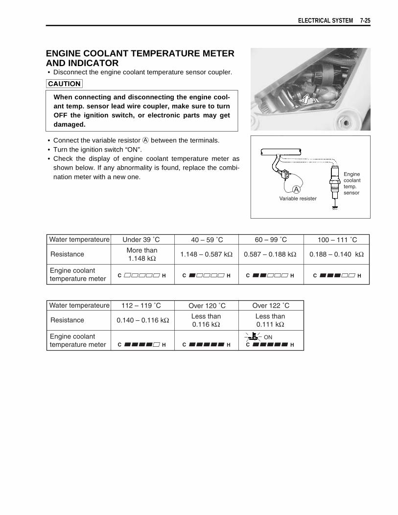
ELECTRICAL SYSTEM 7-25
ENGINE COOLANT TEMPERATURE METER AND INDICATOR• Disconnect the engine coolant temperature sensor coupler.
• Connect the variable resistor
between the terminals.• Turn the ignition switch “ON”.• Check the display of engine coolant temperature meter as
shown below. If any abnormality is found, replace the combi-nation meter with a new one.
When connecting and disconnecting the engine cool-ant temp. sensor lead wire coupler, make sure to turnOFF the ignition switch, or electronic parts may getdamaged.
Variable resister
Enginecoolanttemp.sensor
C H
Resistance More than1.148 kΩ 1.148 – 0.587 kΩ 0.587 – 0.188 kΩ 0.188 – 0.140 kΩ
Engine coolanttemperature meter
Water temperateure
C H C H C H
Under 39 ˚C 40 – 59 ˚C 60 – 99 ˚C 100 – 111 ˚C
C H
Resistance 0.140 – 0.116 kΩ
Engine coolanttemperature meter
Water temperateure
C H C H
112 – 119 ˚C Over 120 ˚C Over 122 ˚C
Less than0.116 kΩ
Less than0.111 kΩ
ON

7-26 ELECTRICAL SYSTEM
FUEL LEVEL GAUGE INSPECTION• Remove the fuel tank. ( 4-52)• Remove the fuel pump. ( 4-55)
Measure the resistance at each fuel level gauge float position. Ifthe resistance is incorrect, replace the fuel level gauge with anew one.
09900-25008: Multi circuit tester set
Tester knob indication: Resistance (Ω)
• Remount the fuel pump. ( 4-58)
Float position Resistance
“F” (Full) Approx. 4 Ω
“E” (Empty) Approx. 182 Ω
Ω
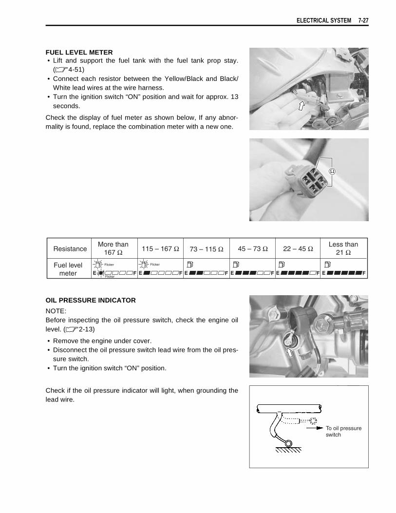
ELECTRICAL SYSTEM 7-27
FUEL LEVEL METER• Lift and support the fuel tank with the fuel tank prop stay.
( 4-51)• Connect each resistor between the Yellow/Black and Black/
White lead wires at the wire harness.• Turn the ignition switch “ON” position and wait for approx. 13
seconds.
Check the display of fuel meter as shown below, If any abnor-mality is found, replace the combination meter with a new one.
OIL PRESSURE INDICATOR
NOTE:Before inspecting the oil pressure switch, check the engine oillevel. ( 2-13)
• Remove the engine under cover.• Disconnect the oil pressure switch lead wire from the oil pres-
sure switch.• Turn the ignition switch “ON” position.
Check if the oil pressure indicator will light, when grounding thelead wire.
E F E FE F E FE FE F
ResistanceMore than
167 ΩLess than
21 Ω115 – 167 Ω 73 – 115 Ω 45 – 73 Ω 22 – 45 Ω
Fuel levelmeter
To oil pressureswitch
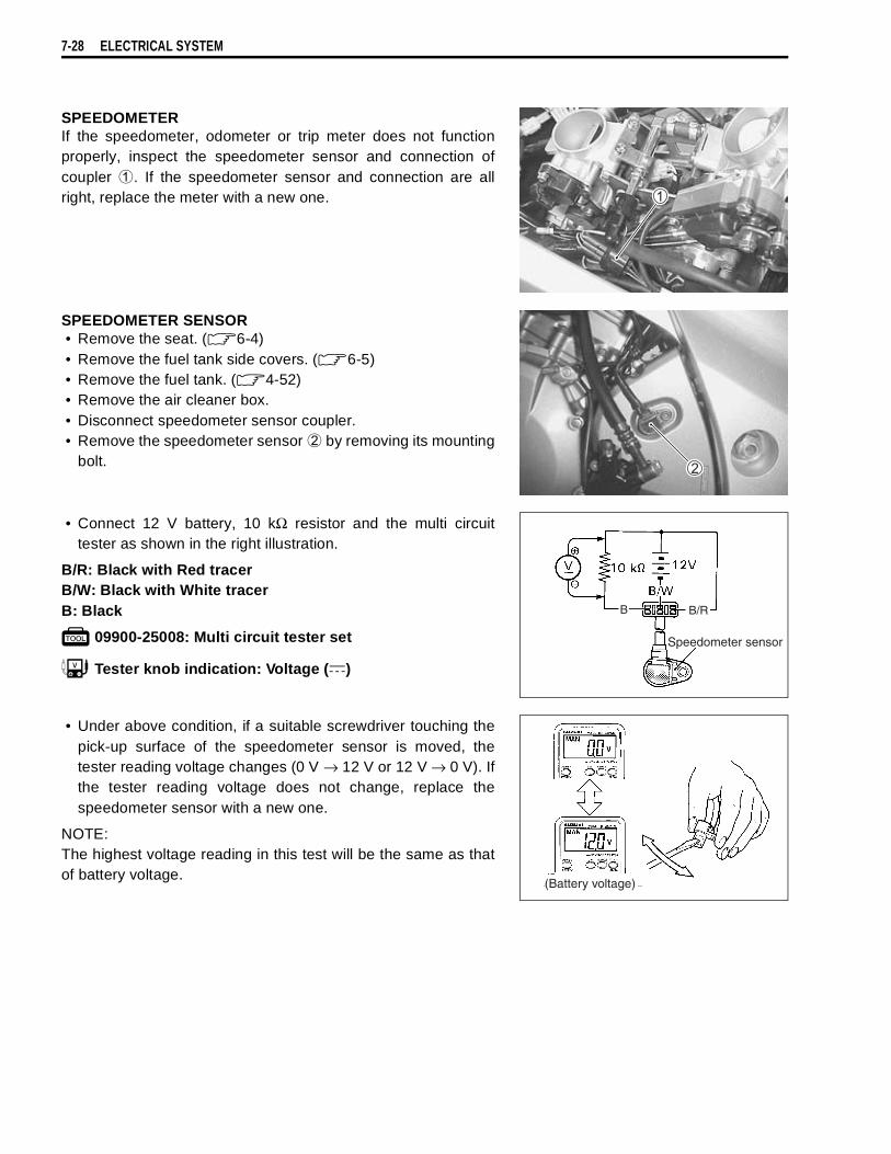
7-28 ELECTRICAL SYSTEM
SPEEDOMETERIf the speedometer, odometer or trip meter does not functionproperly, inspect the speedometer sensor and connection ofcoupler
. If the speedometer sensor and connection are allright, replace the meter with a new one.
SPEEDOMETER SENSOR• Remove the seat. ( 6-4)• Remove the fuel tank side covers. ( 6-5)• Remove the fuel tank. ( 4-52)• Remove the air cleaner box.• Disconnect speedometer sensor coupler.• Remove the speedometer sensor
by removing its mountingbolt.
• Connect 12 V battery, 10 kΩ resistor and the multi circuittester as shown in the right illustration.
B/R: Black with Red tracerB/W: Black with White tracerB: Black
09900-25008: Multi circuit tester set
Tester knob indication: Voltage ( )
• Under above condition, if a suitable screwdriver touching thepick-up surface of the speedometer sensor is moved, thetester reading voltage changes (0 V → 12 V or 12 V → 0 V). Ifthe tester reading voltage does not change, replace thespeedometer sensor with a new one.
NOTE:The highest voltage reading in this test will be the same as thatof battery voltage.
B B/R
Speedometer sensor
(Battery voltage)

ELECTRICAL SYSTEM 7-29
LAMPSHEADLIGHT, BRAKE LIGHT/TAILLIGHT AND TURN SIGNAL LIGHT
HEADLIGHT BEAM ADJUSTMENT• Adjust the headlight beam, both vertical and horizontal.
: Vertical adjuster
: Horizontal adjuster
NOTE:To adjust the headlight beam, adjust the beam horizontally first,then adjust the vertically.
HEADLIGHT12 V 60/50 W12 V 60/50 W + 5 W (ONLY E02, E19)
BRAKE LIGHT/TAIL LIGHT12 V 21/5 W
TURN SIGNAL LIGHT12 V 10 W
Only E02, E19

7-30 ELECTRICAL SYSTEM
RELAYSTURN SIGNAL/SIDE-STAND RELAYThe turn signal/side-stand relay is composed of the turn signalrelay, side-stand relay and diode.
INSPECTIONBefore removing the turn signal/side-stand relay, check theoperation of the turn signal light.If the turn signal light does not illuminate, inspect the bulb, turnsignal switch and circuit connection.If the bulb, turn signal switch and circuit connection are OK, theturn signal relay may be faulty; therefore, replace the turn signal/side-stand relay with a new one.
NOTE:* Make sure that the battery is fully charged.* Refer to the page 7-16 for the side-stand relay and diode
inspection.
STARTER RELAY7-13
FUEL PUMP RELAY4-55
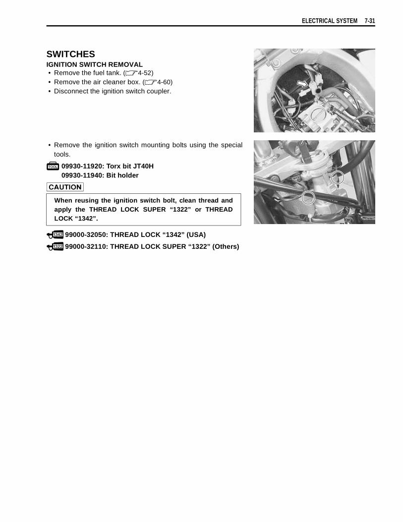
ELECTRICAL SYSTEM 7-31
SWITCHESIGNITION SWITCH REMOVAL• Remove the fuel tank. ( 4-52)• Remove the air cleaner box. ( 4-60)• Disconnect the ignition switch coupler.
• Remove the ignition switch mounting bolts using the specialtools.
09930-11920: Torx bit JT40H09930-11940: Bit holder
99000-32050: THREAD LOCK “1342” (USA)
99000-32110: THREAD LOCK SUPER “1322” (Others)
When reusing the ignition switch bolt, clean thread andapply the THREAD LOCK SUPER “1322” or THREADLOCK “1342”.

7-32 ELECTRICAL SYSTEM
Inspect each switch for continuity with a tester. If any abnormality is found, replace the respective switchassemblies with new ones.
G/Y Ground
ON (engineis stopped)
OFF (engineis running)
ColorPosition
B Ground
ON (engineis stopped)
OFF (engineis running)
ColorPosition
B/Y B/Y
OFFON
ColorPosition
O/G W/B
OFFON
ColorPosition
B/R B/Bl
OFFON
ColorPosition
B/Bl B/W
PUSH
ColorPosition
O/W Y/G
PUSH
ColorPosition
R O O/Y B/W
ONOFF
LOCK
ColorPosition
O/R Y
PUSH
ColorPosition
Lg Lbl B
LPUSH
R
ColorPosition
W Y Y/W
HI ()LO ()
ColorPosition
Lg Lbl B
ONOFF
ColorPosition
O/Bl Gr O/R Y/W
OFF ( )
S ()
ON ()
ColorPosition
R O O/Y B/W Gr Br
ONOFF
LOCKP
ColorPosition
O/B O/W
OFF ()
RUN ()
ColorPosition
IGNITION SWITCH (For E24)
LIGHTING SWITCH(Except for E03, E24, E28, E33)
HAZARD (Except for E03, E24, E28, E33)
OIL PRESSURE SWITCH(For E03, E24, E28, E33)
PASSING LIGHT SWITCH(Except for E03, E28, E33)
DIMMER SWITCH
HORN BUTTON
FRONT BRAKE SWITCH
REAR BRAKE SWITCH
CLUTCH LEVER POSITION SWITCH
ENGINE STOP SWICH
STARTER BUTTON
TURN SIGNAL SWITCH
(For Others)
(For Others)
NOTE:Before inspecting the oil pressure switch, check the engine oil level.(2-13)
B : BlackBr : BrownGr : GrayLbl : Light blueLg : Light greenO : OrangeR : RedY : YellowW : WhiteBl : BlueG : Green
B/Bl : Black with Blue tracerB/W : Black with White tracerB/Y : Black with Yellow tracerB/R : Black with Red tracerG/Y : Green with Yellow tracerO/B : Orange with Black tracerO/Bl : Orange with Blue tracerO/G : Orange with Green tracerO/R : Orange with Red tracerO/W : Orange with White tracerO/Y : Orange with Yellow tracerW/B : White with Black tracerY/G : Yellow with Green tracerY/W : Yellow with White tracer
WIRE COLOR
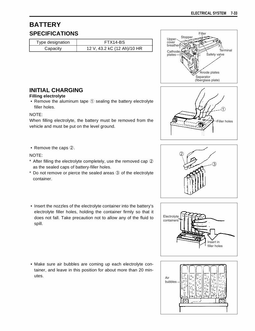
ELECTRICAL SYSTEM 7-33
BATTERYSPECIFICATIONS
INITIAL CHARGINGFilling electrolyte• Remove the aluminum tape
sealing the battery electrolytefiller holes.
NOTE:When filling electrolyte, the battery must be removed from thevehicle and must be put on the level ground.
• Remove the caps
.
NOTE:* After filling the electrolyte completely, use the removed cap
as the sealed caps of battery-filler holes.* Do not remove or pierce the sealed areas
of the electrolytecontainer.
• Insert the nozzles of the electrolyte container into the battery’selectrolyte filler holes, holding the container firmly so that itdoes not fall. Take precaution not to allow any of the fluid tospill.
• Make sure air bubbles are coming up each electrolyte con-tainer, and leave in this position for about more than 20 min-utes.
Type designation FTX14-BSCapacity 12 V, 43.2 kC (12 Ah)/10 HR

7-34 ELECTRICAL SYSTEM
NOTE:If no air bubbles are coming up from a filler port, tap the bottomof the electrolyte container two or three times.Never remove the container from the battery.
• After confirming that the electrolyte has entered the batterycompletely, remove the electrolyte containers from the bat-tery. Wait for about 20 minutes.
• Insert the caps into the filler holes, pressing in firmly so thatthe top of the caps do not protrude above the upper surface ofthe battery’s top cover.
• Using multi circuit tester, measure the battery voltage. Thetester should indicate more than 12.5 – 12.6 V (DC) as shownin the Fig. If the battery voltage is lower than the specification,charge the battery with a battery charger. (Refer to therecharging operation)
NOTE:Initial charging for a new battery is recommended if two yearshave elapsed since the date of manufacture.
* Never use anything except the specified battery.* Once install the caps to the battery; do not remove
the caps.* Do not tap the caps with a hammer when installing
them.
CORRECT INCORRECT
Do not remove the caps on the battery top while charg-ing.
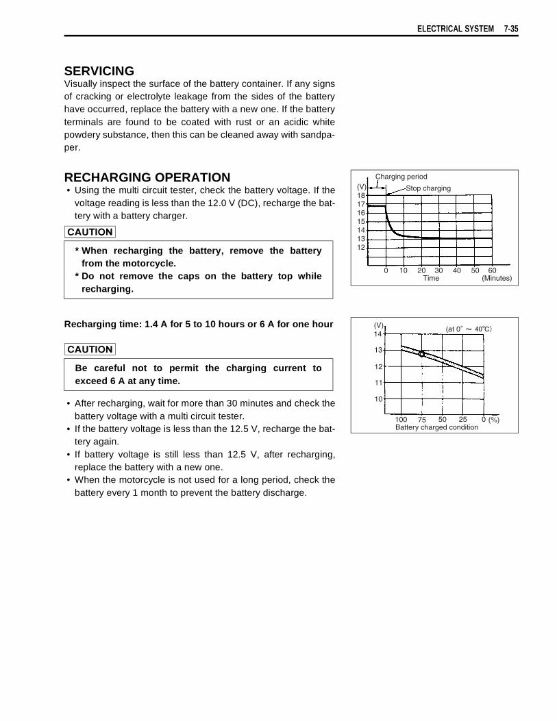
ELECTRICAL SYSTEM 7-35
SERVICINGVisually inspect the surface of the battery container. If any signsof cracking or electrolyte leakage from the sides of the batteryhave occurred, replace the battery with a new one. If the batteryterminals are found to be coated with rust or an acidic whitepowdery substance, then this can be cleaned away with sandpa-per.
RECHARGING OPERATION• Using the multi circuit tester, check the battery voltage. If the
voltage reading is less than the 12.0 V (DC), recharge the bat-tery with a battery charger.
Recharging time: 1.4 A for 5 to 10 hours or 6 A for one hour
• After recharging, wait for more than 30 minutes and check thebattery voltage with a multi circuit tester.
• If the battery voltage is less than the 12.5 V, recharge the bat-tery again.
• If battery voltage is still less than 12.5 V, after recharging,replace the battery with a new one.
• When the motorcycle is not used for a long period, check thebattery every 1 month to prevent the battery discharge.
* When recharging the battery, remove the batteryfrom the motorcycle.
* Do not remove the caps on the battery top whilerecharging.
Be careful not to permit the charging current toexceed 6 A at any time.


8
SERVICING INFORMATION 8-1
CONTENTS
SERVICING INFORMATION
TROUBLESHOOTING ........................................................................8- 2FI SYSTEM MALFUNCTION CODE AND DEFECTIVECONDITION ..................................................................................8- 2ENGINE ........................................................................................8- 4RADIATOR (COOLING SYSTEM) ...............................................8- 9CHASSIS ......................................................................................8-10BRAKES .......................................................................................8-11ELECTRICAL ...............................................................................8-12BATTERY .....................................................................................8-13
WIRE HARNESS, CABLE AND HOSE ROUTING .............................8-14WIRE HARNESS ROUTING ........................................................8-14ENGINE ELECTRICAL PARTS SET-UP .....................................8-17HIGH-TENSION CORD ROUTING ..............................................8-18THROTTLE CABLE ROUTING ....................................................8-19THROTTLE BODY INSTALLATION/HOSE ROUTING ...............8-20CRANKCASE BREATHER HOSE ROUTING .............................8-21CLUTCH HOSE ROUTING ..........................................................8-22COOLING SYSTEM HOSE ROUTING ........................................8-23FRONT BRAKE HOSE ROUTING ...............................................8-24REAR BRAKE HOSE ROUTING .................................................8-25FUEL TANK DRAIN HOSE ROUTING ........................................8-26FUEL TANK INSTALLATION ......................................................8-27PAIR (AIR SUPPLY) SYSTEM HOSE ROUTING ........................8-28SEAT LOCK CABLE ROUTING ..................................................8-29SIDE-STAND SET-UP ..................................................................8-30BRAKE PEDAL/FOOTREST SET-UP .........................................8-30FOOTREST SET-UP ....................................................................8-31HANDLEBAR BALANCER INSTALLATION ..............................8-31
SPECIAL TOOLS ................................................................................8-32TIGHTENING TORQUE ......................................................................8-35
ENGINE ........................................................................................8-35FI SYSTEM PARTS ......................................................................8-36CHASSIS ......................................................................................8-37TIGHTENING TORQUE CHART ..................................................8-38
SERVICE DATA ..................................................................................8-39
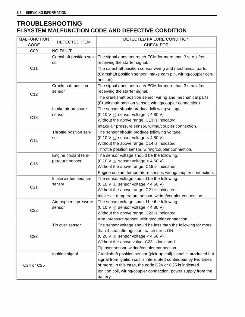
8-2 SERVICING INFORMATION
TROUBLESHOOTINGFI SYSTEM MALFUNCTION CODE AND DEFECTIVE CONDITIONMALFUNCTION
CODEDETECTED ITEM
DETECTED FAILURE CONDITIONCHECK FOR
C00 NO FAULT –––––––––––
C11
Camshaft position sen-sor
The signal does not reach ECM for more than 3 sec. after receiving the starter signal.
The camshaft position sensor wiring and mechanical parts. (Camshaft position sensor, intake cam pin, wiring/coupler con-nection)
C12
Crankshaft position sensor
The signal does not reach ECM for more than 3 sec. after receiving the starter signal.
The crankshaft position sensor wiring and mechanical parts. (Crankshaft position sensor, wiring/coupler connection)
C13
Intake air pressure sensor
The sensor should produce following voltage.(0.10 V sensor voltage < 4.80 V)Without the above range, C13 is indicated.
Intake air pressure sensor, wiring/coupler connection.
C14
Throttle position sen-sor
The sensor should produce following voltage.(0.10 V sensor voltage < 4.80 V)Without the above range, C14 is indicated.Throttle position sensor, wiring/coupler connection.
C15
Engine coolant tem-perature sensor
The sensor voltage should be the following.(0.10 V sensor voltage < 4.60 V)Without the above range, C15 is indicated.
Engine coolant temperature sensor, wiring/coupler connection.
C21
Intake air temperature sensor
The sensor voltage should be the following.(0.10 V sensor voltage < 4.60 V)Without the above range, C21 is indicated.
Intake air temperature sensor, wiring/coupler connection.
C22
Atmospheric pressure sensor
The sensor voltage should be the following.(0.10 V sensor voltage < 4.80 V)Without the above range, C22 is indicated.Atm. pressure sensor, wiring/coupler connection.
C23
Tip over sensor The sensor voltage should be less than the following for more than 4 sec. after ignition switch turns ON.(0.20 V sensor voltage < 4.60 V)Without the above value, C23 is indicated.Tip over sensor, wiring/coupler connection.
C24 or C25
Ignition signal Crankshaft position sensor (pick-up coil) signal is produced but signal from ignition coil is interrupted continuous by two times or more. In this case, the code C24 or C25 is indicated.
Ignition coil, wiring/coupler connection, power supply from the battery.
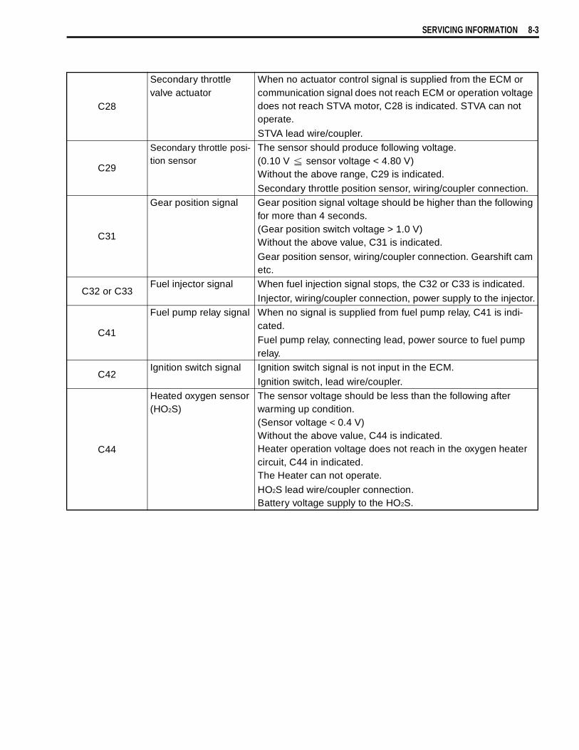
SERVICING INFORMATION 8-3
C28
Secondary throttle valve actuator
When no actuator control signal is supplied from the ECM or communication signal does not reach ECM or operation voltage does not reach STVA motor, C28 is indicated. STVA can not operate.
STVA lead wire/coupler.
C29
Secondary throttle posi-tion sensor
The sensor should produce following voltage. (0.10 V sensor voltage < 4.80 V)Without the above range, C29 is indicated.
Secondary throttle position sensor, wiring/coupler connection.
C31
Gear position signal Gear position signal voltage should be higher than the following for more than 4 seconds.(Gear position switch voltage > 1.0 V)Without the above value, C31 is indicated.
Gear position sensor, wiring/coupler connection. Gearshift cam etc.
C32 or C33Fuel injector signal When fuel injection signal stops, the C32 or C33 is indicated.
Injector, wiring/coupler connection, power supply to the injector.
C41
Fuel pump relay signal When no signal is supplied from fuel pump relay, C41 is indi-cated.Fuel pump relay, connecting lead, power source to fuel pump relay.
C42Ignition switch signal Ignition switch signal is not input in the ECM.
Ignition switch, lead wire/coupler.
C44
Heated oxygen sensor(HO2S)
The sensor voltage should be less than the following after warming up condition.(Sensor voltage < 0.4 V)Without the above value, C44 is indicated.Heater operation voltage does not reach in the oxygen heater circuit, C44 in indicated.The Heater can not operate.
HO2S lead wire/coupler connection.Battery voltage supply to the HO2S.
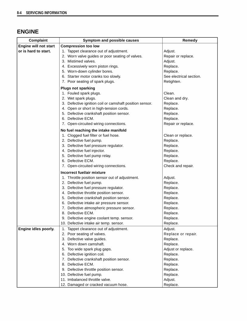
8-4 SERVICING INFORMATION
ENGINEComplaint Symptom and possible causes Remedy
Engine will not start or is hard to start.
Compression too low1. Tappet clearance out of adjustment.2. Worn valve guides or poor seating of valves.3. Mistimed valves.4. Excessively worn piston rings.5. Worn-down cylinder bores.6. Starter motor cranks too slowly.7. Poor seating of spark plugs.
Plugs not sparking1. Fouled spark plugs.2. Wet spark plugs.3. Defective ignition coil or camshaft position sensor.4. Open or short in high-tension cords.5. Defective crankshaft position sensor.6. Defective ECM.7. Open-circuited wiring connections.
No fuel reaching the intake manifold1. Clogged fuel filter or fuel hose.2. Defective fuel pump.3. Defective fuel pressure regulator.4. Defective fuel injector.5. Defective fuel pump relay.6. Defective ECM.7. Open-circuited wiring connections.
Incorrect fuel/air mixture1. Throttle position sensor out of adjustment.2. Defective fuel pump.3. Defective fuel pressure regulator.4. Defective throttle position sensor.5. Defective crankshaft position sensor.6. Defective intake air pressure sensor.7. Defective atmospheric pressure sensor.8. Defective ECM.9. Defective engine coolant temp. sensor.
10. Defective intake air temp. sensor.
Adjust.Repair or replace.Adjust.Replace.Replace.See electrical section.Retighten.
Clean.Clean and dry.Replace.Replace.Replace.Replace.Repair or replace.
Clean or replace.Replace.Replace.Replace.Replace.Replace.Check and repair.
Adjust.Replace.Replace.Replace.Replace.Replace.Replace.Replace.Replace.Replace.
Engine idles poorly. 1. Tappet clearance out of adjustment.2. Poor seating of valves.3. Defective valve guides.4. Worn down camshaft.5. Too wide spark plug gaps.6. Defective ignition coil.7. Defective crankshaft position sensor.8. Defective ECM.9. Defective throttle position sensor.
10. Defective fuel pump.11. Imbalanced throttle valve.12. Damaged or cracked vacuum hose.
Adjust.Replace or repair.Replace.Replace.Adjust or replace.Replace.Replace.Replace.Replace.Replace.Adjust.Replace.

SERVICING INFORMATION 8-5
Complaint Symptom and possible causes RemedyEngine stalls often Incorrect fuel/air mixture
1. Defective intake air pressure sensor or circuit.2. Clogged fuel filter.3. Defective fuel pump.4. Defective fuel pressure regulator.5. Damaged or cracked vacuum hose.6. Defective engine coolant temp. sensor.7. Defective thermostat.8. Defective intake air temp. sensor.
Fuel injector improperly operating1. Defective fuel injector.2. No injection signal from ECM.3. Open or short circuited wiring connection.4. Defective battery or low battery voltage.
Control circuit or sensor improperly operating1. Defective ECM.2. Defective fuel pressure regulator.3. Defective throttle position sensor.4. Defective intake air temp. sensor.5. Defective camshaft position sensor.6. Defective crankshaft position sensor.7. Defective engine coolant temp. sensor.8. Defective fuel pump relay.
Engine internal parts improperly operating1. Fouled spark plugs.2. Defective crankshaft position sensor or ECM.3. Clogged fuel hose.4. Tappet clearance out of adjustment.
Repair or replace.Clean or replace.Replace.Replace.Replace.Replace.Replace.Replace.
Replace.Repair or replace.Repair or replace.Replace or recharge.
Replace.Replace.Replace.Replace.Replace.Replace.Replace.Replace.
Clean.Replace.Clean.Adjust.
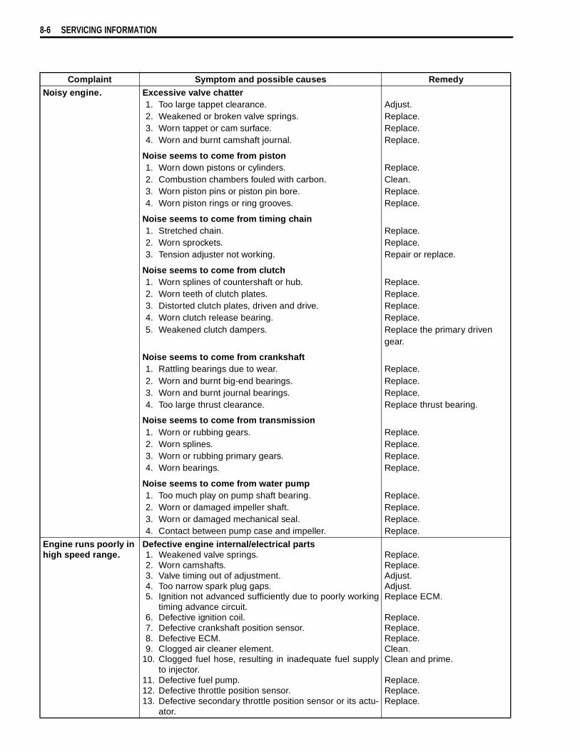
8-6 SERVICING INFORMATION
Complaint Symptom and possible causes RemedyNoisy engine. Excessive valve chatter
1. Too large tappet clearance.2. Weakened or broken valve springs.3. Worn tappet or cam surface.4. Worn and burnt camshaft journal.
Noise seems to come from piston1. Worn down pistons or cylinders.2. Combustion chambers fouled with carbon.3. Worn piston pins or piston pin bore.4. Worn piston rings or ring grooves.
Noise seems to come from timing chain1. Stretched chain.2. Worn sprockets.3. Tension adjuster not working.
Noise seems to come from clutch1. Worn splines of countershaft or hub.2. Worn teeth of clutch plates.3. Distorted clutch plates, driven and drive.4. Worn clutch release bearing.5. Weakened clutch dampers.
Noise seems to come from crankshaft1. Rattling bearings due to wear.2. Worn and burnt big-end bearings.3. Worn and burnt journal bearings.4. Too large thrust clearance.
Noise seems to come from transmission1. Worn or rubbing gears.2. Worn splines.3. Worn or rubbing primary gears.4. Worn bearings.
Noise seems to come from water pump1. Too much play on pump shaft bearing.2. Worn or damaged impeller shaft.3. Worn or damaged mechanical seal.4. Contact between pump case and impeller.
Adjust.Replace.Replace.Replace.
Replace.Clean.Replace.Replace.
Replace.Replace.Repair or replace.
Replace.Replace.Replace.Replace.Replace the primary driven gear.
Replace.Replace.Replace.Replace thrust bearing.
Replace.Replace.Replace.Replace.
Replace.Replace.Replace.Replace.
Engine runs poorly in high speed range.
Defective engine internal/electrical parts1. Weakened valve springs.2. Worn camshafts.3. Valve timing out of adjustment.4. Too narrow spark plug gaps.5. Ignition not advanced sufficiently due to poorly working
timing advance circuit.6. Defective ignition coil.7. Defective crankshaft position sensor.8. Defective ECM.9. Clogged air cleaner element.
10. Clogged fuel hose, resulting in inadequate fuel supplyto injector.
11. Defective fuel pump.12. Defective throttle position sensor.13. Defective secondary throttle position sensor or its actu-
ator.
Replace.Replace.Adjust.Adjust.Replace ECM.
Replace.Replace.Replace.Clean.Clean and prime.
Replace.Replace.Replace.
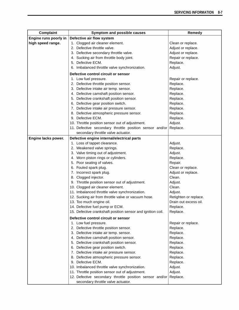
SERVICING INFORMATION 8-7
Complaint Symptom and possible causes RemedyEngine runs poorly in high speed range.
Defective air flow system1. Clogged air cleaner element.2. Defective throttle valve.3. Defective secondary throttle valve.4. Sucking air from throttle body joint.5. Defective ECM.6. Imbalanced throttle valve synchronization.
Defective control circuit or sensor1. Low fuel pressure.2. Defective throttle position sensor.3. Defective intake air temp. sensor.4. Defective camshaft position sensor.5. Defective crankshaft position sensor.6. Defective gear position switch.7. Defective intake air pressure sensor.8. Defective atmospheric pressure sensor.9. Defective ECM.
10. Throttle position sensor out of adjustment.11. Defective secondary throttle position sensor and/or
secondary throttle valve actuator.
Clean or replace.Adjust or replace.Adjust or replace.Repair or replace.Replace.Adjust.
Repair or replace.Replace.Replace.Replace.Replace.Replace.Replace.Replace.Replace.Adjust.Replace.
Engine lacks power. Defective engine internal/electrical parts1. Loss of tappet clearance.2. Weakened valve springs.3. Valve timing out of adjustment.4. Worn piston rings or cylinders.5. Poor seating of valves.6. Fouled spark plug.7. Incorrect spark plug.8. Clogged injector.9. Throttle position sensor out of adjustment.
10. Clogged air cleaner element.11. Imbalanced throttle valve synchronization.12. Sucking air from throttle valve or vacuum hose.13. Too much engine oil.14. Defective fuel pump or ECM.15. Defective crankshaft position sensor and ignition coil.
Defective control circuit or sensor1. Low fuel pressure.2. Defective throttle position sensor.3. Defective intake air temp. sensor.4. Defective camshaft position sensor.5. Defective crankshaft position sensor.6. Defective gear position switch.7. Defective intake air pressure sensor.8. Defective atmospheric pressure sensor.9. Defective ECM.
10. Imbalanced throttle valve synchronization.11. Throttle position sensor out of adjustment.12. Defective secondary throttle position sensor and/or
secondary throttle valve actuator.
Adjust.Replace.Adjust.Replace.Repair.Clean or replace.Adjust or replace.Clean.Adjust.Clean.Adjust.Retighten or replace.Drain out excess oil.Replace.Replace.
Repair or replace.Replace.Replace.Replace.Replace.Replace.Replace.Replace.Replace.Adjust.Adjust.Replace.
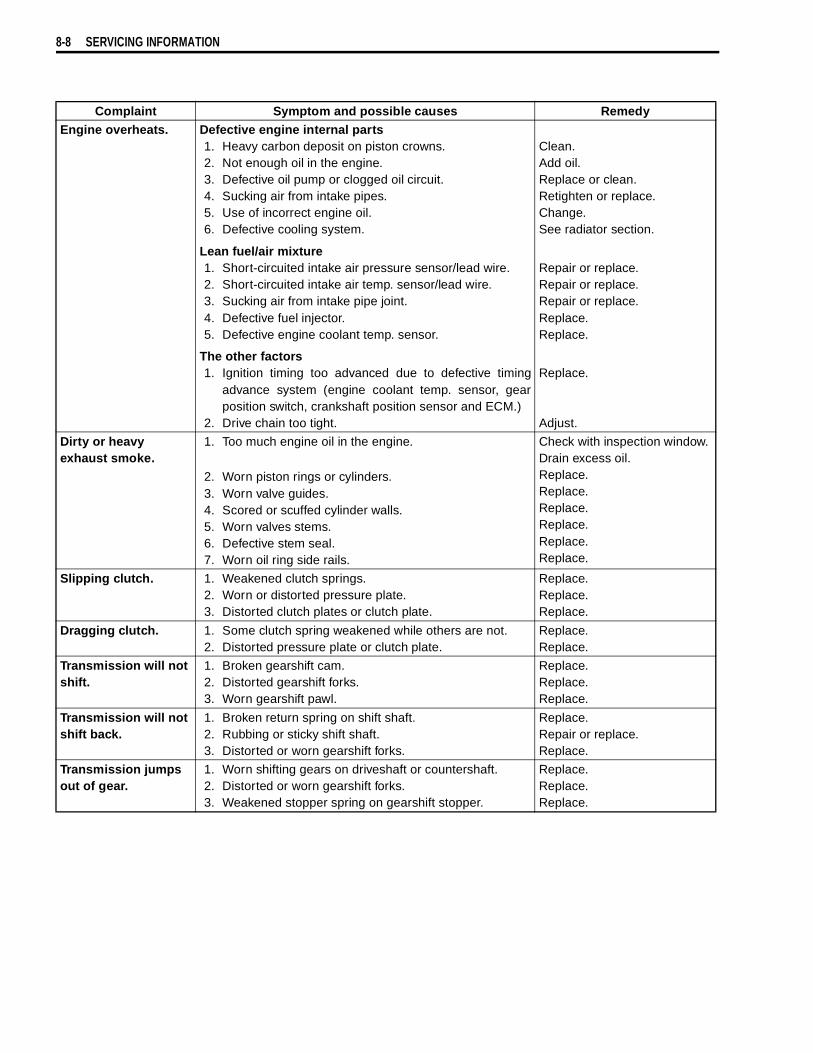
8-8 SERVICING INFORMATION
Complaint Symptom and possible causes RemedyEngine overheats. Defective engine internal parts
1. Heavy carbon deposit on piston crowns.2. Not enough oil in the engine.3. Defective oil pump or clogged oil circuit.4. Sucking air from intake pipes.5. Use of incorrect engine oil.6. Defective cooling system.
Lean fuel/air mixture1. Short-circuited intake air pressure sensor/lead wire.2. Short-circuited intake air temp. sensor/lead wire.3. Sucking air from intake pipe joint.4. Defective fuel injector.5. Defective engine coolant temp. sensor.
The other factors1. Ignition timing too advanced due to defective timing
advance system (engine coolant temp. sensor, gearposition switch, crankshaft position sensor and ECM.)
2. Drive chain too tight.
Clean.Add oil.Replace or clean.Retighten or replace.Change.See radiator section.
Repair or replace.Repair or replace.Repair or replace.Replace.Replace.
Replace.
Adjust.
Dirty or heavy exhaust smoke.
1. Too much engine oil in the engine.
2. Worn piston rings or cylinders.3. Worn valve guides.4. Scored or scuffed cylinder walls.5. Worn valves stems.6. Defective stem seal.7. Worn oil ring side rails.
Check with inspection window. Drain excess oil.Replace.Replace.Replace.Replace.Replace.Replace.
Slipping clutch. 1. Weakened clutch springs.2. Worn or distorted pressure plate.3. Distorted clutch plates or clutch plate.
Replace.Replace.Replace.
Dragging clutch. 1. Some clutch spring weakened while others are not.2. Distorted pressure plate or clutch plate.
Replace.Replace.
Transmission will not shift.
1. Broken gearshift cam.2. Distorted gearshift forks.3. Worn gearshift pawl.
Replace.Replace.Replace.
Transmission will not shift back.
1. Broken return spring on shift shaft.2. Rubbing or sticky shift shaft.3. Distorted or worn gearshift forks.
Replace.Repair or replace.Replace.
Transmission jumps out of gear.
1. Worn shifting gears on driveshaft or countershaft.2. Distorted or worn gearshift forks.3. Weakened stopper spring on gearshift stopper.
Replace.Replace.Replace.

SERVICING INFORMATION 8-9
RADIATOR (COOLING SYSTEM)Complaint Symptom and possible causes Remedy
Engine overheats. 1. Not enough engine coolant.2. Radiator core clogged with dirt or scale.3. Faulty cooling fan.4. Defective cooling fan thermo-switch.5. Clogged water passage.6. Air trapped in the cooling circuit.7. Defective water pump.8. Use of incorrect engine coolant.9. Defective thermostat.
Add engine coolant.Clean.Repair or replace.Replace.Clean.Bleed air.Replace.Replace.Replace.
Engine overcools. 1. Defective cooling fan thermo-switch.2. Extremely cold weather.3. Defective thermostat.
Replace.Put on radiator cover.Replace.
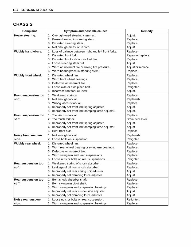
8-10 SERVICING INFORMATION
CHASSISComplaint Symptom and possible causes Remedy
Heavy steering. 1. Overtightened steering stem nut.2. Broken bearing in steering stem.3. Distorted steering stem.4. Not enough pressure in tires.
Adjust.Replace.Replace.Adjust.
Wobbly handlebars. 1. Loss of balance between right and left front forks.2. Distorted front fork.3. Distorted front axle or crooked tire.4. Loose steering stem nut.5. Worn or incorrect tire or wrong tire pressure.6. Worn bearing/race in steering stem.
Replace.Repair or replace.Replace.Adjust.Adjust or replace.Replace.
Wobbly front wheel. 1. Distorted wheel rim.2. Worn front wheel bearings.3. Defective or incorrect tire.4. Loose axle or axle pinch bolt.5. Incorrect front fork oil level.
Replace.Replace.Replace.Retighten.Adjust.
Front suspension too soft.
1. Weakened springs.2. Not enough fork oil.3. Wrong viscous fork oil.4. Improperly set front fork spring adjuster.5. Improperly set front fork damping force adjuster.
Replace.Replenish.Replace.Adjust.Adjust.
Front suspension too stiff.
1. Too viscous fork oil.2. Too much fork oil.3. Improperly set front fork spring adjuster.4. Improperly set front fork damping force adjuster.5. Bent front axle.
Replace.Drain excess oil.Adjust.Adjust.Replace.
Noisy front suspen-sion.
1. Not enough fork oil.2. Loose bolts on suspension.
Replenish.Retighten.
Wobbly rear wheel. 1. Distorted wheel rim.2. Worn rear wheel bearing or swingarm bearings.3. Defective or incorrect tire.4. Worn swingarm and rear suspensions.5. Loose nuts or bolts on rear suspensions.
Replace.Replace.Replace.Replace.Retighten.
Rear suspension too soft.
1. Weakened spring of shock absorber.2. Leakage of oil from shock absorber.3. Improperly set rear spring unit adjuster.4. Improperly set damping force adjuster.
Replace.Replace.Adjust.Adjust.
Rear suspension too stiff.
1. Bent shock absorber shaft.2. Bent swingarm pivot shaft.3. Worn swingarm and suspension bearings.4. Improperly set rear suspension adjuster.5. Improperly set damping force adjuster.
Replace.Replace.Replace.Adjust.Adjust.
Noisy rear suspen-sion.
1. Loose nuts or bolts on rear suspension.2. Worn swingarm and suspension bearings.
Retighten.Replace.
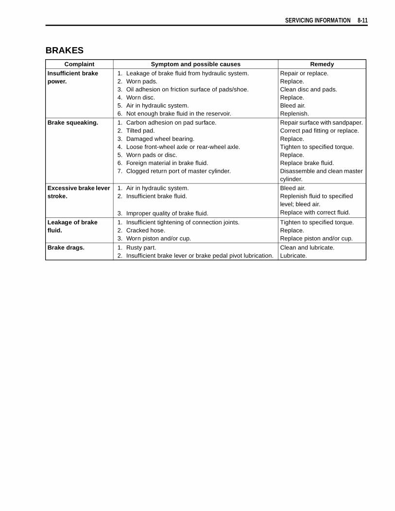
SERVICING INFORMATION 8-11
BRAKESComplaint Symptom and possible causes Remedy
Insufficient brake power.
1. Leakage of brake fluid from hydraulic system.2. Worn pads.3. Oil adhesion on friction surface of pads/shoe.4. Worn disc.5. Air in hydraulic system.6. Not enough brake fluid in the reservoir.
Repair or replace.Replace.Clean disc and pads.Replace.Bleed air.Replenish.
Brake squeaking. 1. Carbon adhesion on pad surface.2. Tilted pad.3. Damaged wheel bearing.4. Loose front-wheel axle or rear-wheel axle.5. Worn pads or disc.6. Foreign material in brake fluid.7. Clogged return port of master cylinder.
Repair surface with sandpaper. Correct pad fitting or replace.Replace.Tighten to specified torque.Replace.Replace brake fluid.Disassemble and clean master cylinder.
Excessive brake lever stroke.
1. Air in hydraulic system.2. Insufficient brake fluid.
3. Improper quality of brake fluid.
Bleed air.Replenish fluid to specified level; bleed air.Replace with correct fluid.
Leakage of brake fluid.
1. Insufficient tightening of connection joints.2. Cracked hose.3. Worn piston and/or cup.
Tighten to specified torque.Replace.Replace piston and/or cup.
Brake drags. 1. Rusty part.2. Insufficient brake lever or brake pedal pivot lubrication.
Clean and lubricate.Lubricate.

8-12 SERVICING INFORMATION
ELECTRICALComplaint Symptom and possible causes Remedy
No sparking or poor sparking.
1. Defective ignition coil or camshaft position sensor.2. Defective spark plugs.3. Defective crankshaft position sensor.4. Defective ECM.5. Defective tip over sensor.6. Open-circuited wiring connections.
Replace.Replace.Replace.Replace.Replace.Check and repair.
Spark plugs soon become fouled with carbon.
1. Mixture too rich.2. Idling speed set too high.
3. Incorrect gasoline.4. Dirty air cleaner element.5. Too cold spark plugs.
Consult FI system.Adjust fast idle or throttle stop screw.Change.Clean or replace.Replace with hot type plugs.
Spark plugs become fouled too soon.
1. Worn piston rings.2. Worn piston or cylinders.3. Excessive clearance of valve stems in valve guides.4. Worn stem oil seal.
Replace.Replace.Replace.Replace.
Spark plug electrodes overheat or burn.
1. Too hot spark plugs.2. Overheated the engine.3. Loose spark plugs.4. Too lean mixture.
Replace with cold type plugs.Tune up.Retighten.Consult FI system.
Generator does not charge.
1. Open- or short-circuited lead wires, or loose lead con-nections.
2. Short-circuited, grounded or open generator coils.3. Short-circuited or panctured regulator/rectifiers.
Repair or replace or retighten.
Replace.Replace.
Generator does charge, but charging rate is below the specification.
1. Lead wires tend to get short- or open-circuited orloosely connected at terminals.
2. Grounded or open-circuited stator coils or generator.3. Defective regulator/rectifier.4. Defective cell plates in the battery.
Repair or retighten.
Replace.Replace.Replace the battery.
Generator over-charges.
1. Internal short-circuit in the battery.2. Damaged or defective resistor element in the regulator/
rectifier.3. Poorly grounded regulator/rectifier.
Replace the battery.Replace.
Clean and tighten ground con-nection.
Unstable charging. 1. Lead wire insulation frayed due to vibration, resulting inintermittent short-circuiting.
2. Internally short-circuited generator.3. Defective regulator/rectifier.
Repair or replace.
Replace.Replace.
Starter button is not effective.
1. Run down battery.2. Defective switch contacts.3. Brushes not seating properly on starter motor commu-
tator.4. Defective starter relay/starter interlock switch.5. Defective main fuse.
Repair or replace.Replace.Repair or replace.
Replace.Replace.
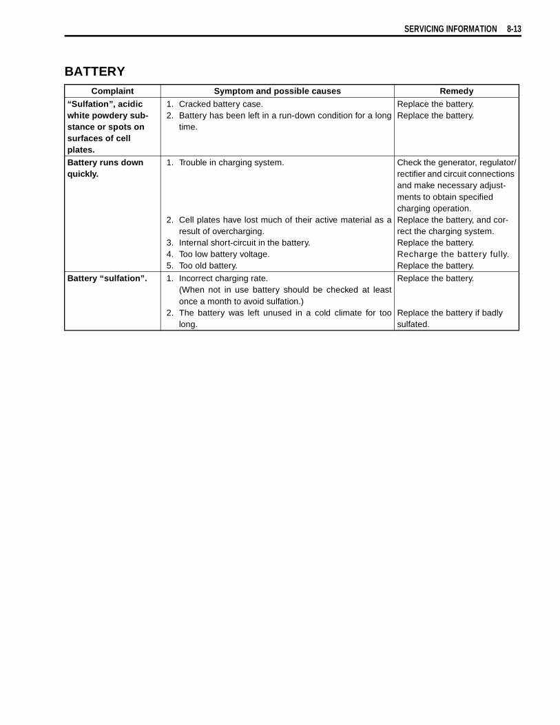
SERVICING INFORMATION 8-13
BATTERYComplaint Symptom and possible causes Remedy
“Sulfation”, acidic white powdery sub-stance or spots on surfaces of cell plates.
1. Cracked battery case.2. Battery has been left in a run-down condition for a long
time.
Replace the battery.Replace the battery.
Battery runs down quickly.
1. Trouble in charging system.
2. Cell plates have lost much of their active material as aresult of overcharging.
3. Internal short-circuit in the battery.4. Too low battery voltage.5. Too old battery.
Check the generator, regulator/rectifier and circuit connections and make necessary adjust-ments to obtain specified charging operation.Replace the battery, and cor-rect the charging system.Replace the battery.Recharge the battery fully.Replace the battery.
Battery “sulfation”. 1. Incorrect charging rate.(When not in use battery should be checked at leastonce a month to avoid sulfation.)
2. The battery was left unused in a cold climate for toolong.
Replace the battery.
Replace the battery if badly sulfated.

8-14 SERVICING INFORMATION
WIRE HARNESS, CABLE AND HOSE ROUTINGWIRE HARNESS ROUTING
Sta
rter
rel
ayF
use
box
Reg
ulat
or/r
ectif
ier
Cla
mp
Cla
mp
Cla
mp
Cla
mp
Cla
mp
Han
dleb
ar s
witc
hco
uple
r (L
)
Inje
ctor
cou
pler
ST
PS
cou
pler
Cla
mp
Spe
ed s
enso
rco
uple
rF
uel p
ump
coup
ler
Cla
mp
Sta
rter
rel
ay
AP
sen
sor
Sea
t loc
k ca
ble
TO s
enso
rF
P r
elay
EC
MF
use
box
HO
2 se
nsor
cou
pler
CM
P s
enso
rE
CT
sen
sor
Han
dleb
ar s
witc
h co
uple
r (R
)
Igni
tion
switc
h co
uple
r
Fix
ed c
lam
p Igni
tion
coil
Cla
mp
Fix
ed c
lam
p
Thr
ottle
cab
les
Han
dleb
ar s
witc
h (L
)le
ad w
ires
Cla
mp

SERVICING INFORMATION 8-15
Fixed clamp
Fixed clamp
Clamp
Clamp
Headlight
Clamp
HO2 sensor
Clamp
IAT sensor
IAP sensor
CMP sensor
Fixed clamp

8-16 SERVICING INFORMATION
Cla
mp
HO
2 se
nsor
Pas
s th
e H
O2
sens
or le
ad w
ires
over
the
engi
ne u
nder
cov
er b
rack
et.
Cla
mp

SERVICING INFORMATION 8-17
ENGINE ELECTRICAL PARTS SET-UPApply bond to the grooveof the grommet.
6.5 N·m(0.65 kgf-m, 4.7 lb-ft)
12 N·m(1.2 kgf-m, 8.5 lb-ft)
Apply bond to the grooveof the grommet.
6.5 N·m(0.65 kgf-m, 4.7 lb-ft)
10 N·m
( )1.0 kgf-m,7.3 lb-ft
Engine ground wire
6 N·m
( )0.6 kgf-m,4.3 lb-ft
CMP sensor
10 N·m(1.0 kgf-m, 7.3 lb-ft)
Forward
#2 Cylinder
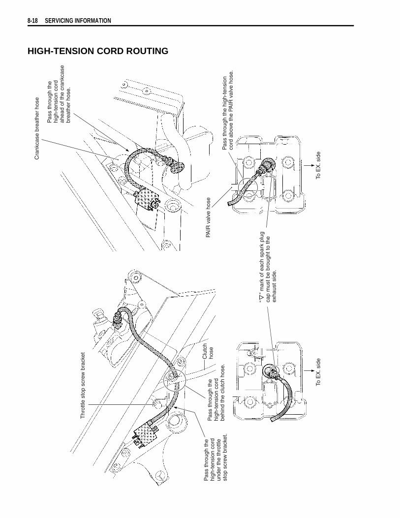
8-18 SERVICING INFORMATION
HIGH-TENSION CORD ROUTING
Thr
ottle
sto
p sc
rew
bra
cket Clu
tch
hose
To E
X. s
ide
To E
X. s
ide
“
” mar
k of
eac
h sp
ark
plug
cap
mus
t be
brou
ght t
o th
e ex
haus
t sid
e.
Pas
s th
roug
h th
e hi
gh-t
ensi
on
cord
abo
ve th
e PA
IR v
alve
hos
e.
PAIR
val
ve h
ose
Cra
nkca
se b
reat
her
hose
Pas
s th
roug
h th
ehi
gh-t
ensi
on c
ord
unde
r th
e th
rottl
est
op s
crew
bra
cket
.
Pas
s th
roug
h th
ehi
gh-t
ensi
on c
ord
behi
nd th
e cl
utch
hos
e.
Pas
s th
roug
h th
ehi
gh-t
ensi
on c
ord
ahea
d of
the
cran
kcas
ebr
eath
er h
ose.
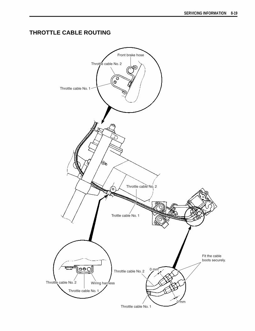
SERVICING INFORMATION 8-19
THROTTLE CABLE ROUTING
Front brake hose
Throttle cable No. 2
Throttle cable No. 1
Trottle cable No. 1
Throttle cable No. 2
Fit the cableboots securely.
0 mm
0 mmThrottle cable No. 2
Throttle cable No. 1
Throttle cable No. 1
Wiring harnessThrottle cable No. 2
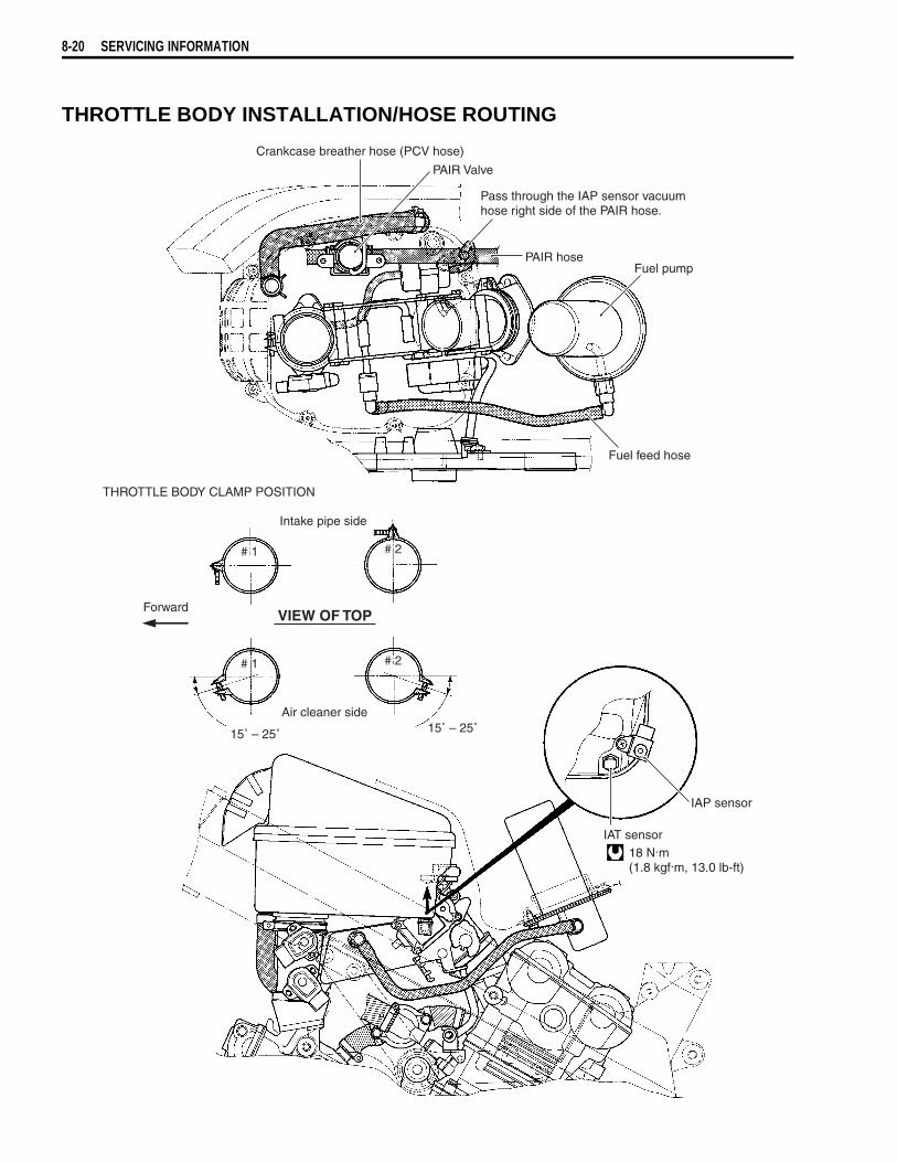
8-20 SERVICING INFORMATION
THROTTLE BODY INSTALLATION/HOSE ROUTING
18 N.m(1.8 kgf.m, 13.0 lb-ft)
Crankcase breather hose (PCV hose)
PAIR Valve
Pass through the IAP sensor vacuumhose right side of the PAIR hose.
PAIR hoseFuel pump
Fuel feed hose
IAP sensor
IAT sensor
# 1
# 1
# 2
# 2
Forward
Intake pipe side
15˚ – 25˚ 15˚ – 25˚Air cleaner side
VIEW OF TOP
THROTTLE BODY CLAMP POSITION
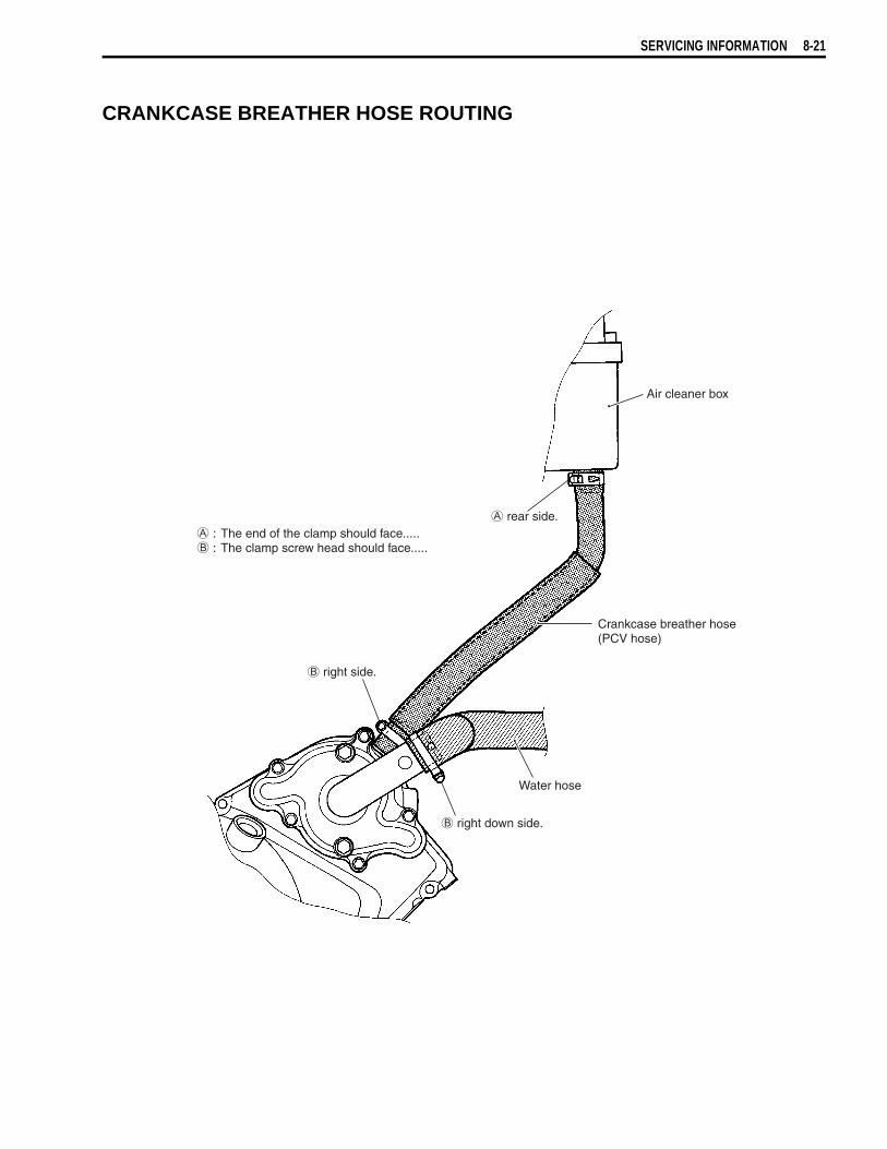
SERVICING INFORMATION 8-21
CRANKCASE BREATHER HOSE ROUTING
right down side.
right side.
: The end of the clamp should face..... : The clamp screw head should face.....
rear side.
Water hose
Air cleaner box
Crankcase breather hose(PCV hose)
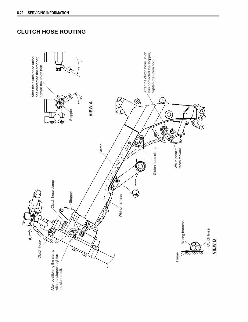
8-22 SERVICING INFORMATION
CLUTCH HOSE ROUTING
Sto
pper
Sto
pper
Afte
r th
e cl
utch
hos
e un
ion
has
cont
acte
d th
e st
oppe
r,tig
hten
the
unio
n bo
lt.
35˚
35˚
VIE
W A
A
B
VIE
W B
Clu
tch
hose
Afte
r po
sitio
ning
the
clam
pw
ith th
e st
oppe
r, tig
hten
the
clam
p bo
lt.
Clu
tch
hose
cla
mp
Wiri
ng h
arne
ss
Cla
mp
Clu
tch
hose
cla
mp
Whi
te p
aint
face
s fo
rwar
d.
Afte
r th
e cl
utch
hos
e un
ion
has
cont
acte
d th
e st
oppe
r,tig
hten
the
unio
n bo
lt.
Fram
e
Clu
tch
hose
Wiri
ng h
arne
ss
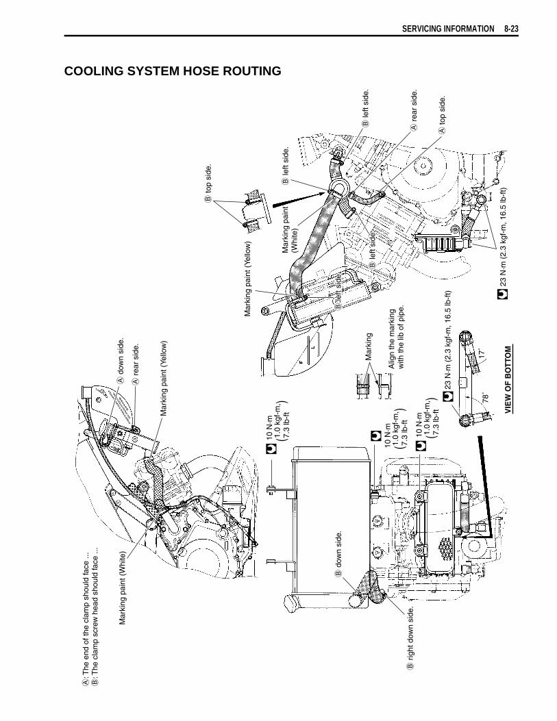
SERVICING INFORMATION 8-23
COOLING SYSTEM HOSE ROUTING
d
own
side
.
r
ear
side
.
Mar
king
pai
nt (
Yello
w)
Mar
king
pai
nt (
Whi
te)
10 N
·m
( )
1.0
kgf-
m,
7.3
lb-f
t
10 N
·m
( )
1.0
kgf-
m,
7.3
lb-f
t
10 N
·m
( )
1.0
kgf-
m,
7.3
lb-f
t
Mar
king
Alig
n th
e m
arki
ngw
ith th
e lib
of p
ipe.
23 N
·m (
2.3
kgf-
m, 1
6.5
lb-f
t)
78˚
17˚
VIE
W O
F B
OT
TOM
d
own
side
.
r
ight
dow
n si
de.
to
p si
de.
Mar
king
pai
nt (
Yello
w)
Mar
king
pai
nt(W
hite
)
left
side
.
le
ft si
de.
r
ear
side
.
le
ft si
de.
to
p si
de.
le
ft si
de.
23 N
·m (
2.3
kgf-
m, 1
6.5
lb-f
t)
: T
he e
nd o
f the
cla
mp
shou
ld fa
ce ..
.
: The
cla
mp
scre
w h
ead
shou
ld fa
ce ..
.
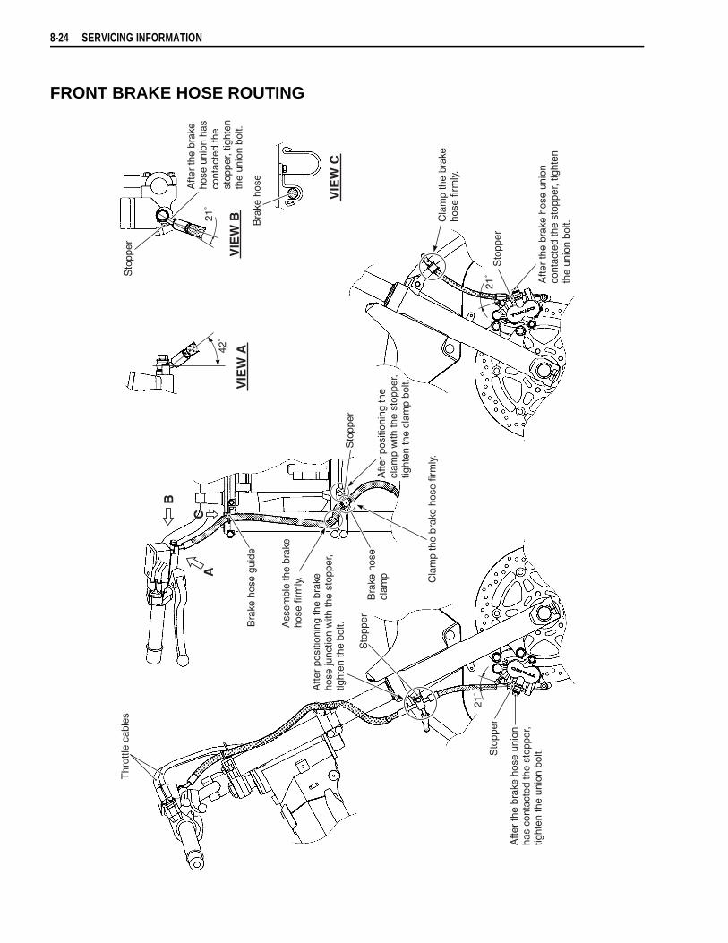
8-24 SERVICING INFORMATION
FRONT BRAKE HOSE ROUTING
VIE
W A
A
B
CC
VIE
W B
VIE
W C
Thr
ottle
cab
les
Sto
pper
Afte
r po
sitio
ning
the
brak
eho
se ju
nctio
n w
ith th
e st
oppe
r,tig
hten
the
bolt.
21˚
21˚
Sto
pper
Afte
r th
e br
ake
hose
uni
onha
s co
ntac
ted
the
stop
per,
tight
en th
e un
ion
bolt.
Bra
ke h
ose
guid
e
Bra
ke h
ose
clam
p Cla
mp
the
brak
e ho
se fi
rmly
.
Ass
embl
e th
e br
ake
hose
firm
ly.
Afte
r po
sitio
ning
the
clam
p w
ith th
e st
oppe
r,tig
hten
the
clam
p bo
lt.
Sto
pper
Sto
pper
Afte
r th
e br
ake
hose
uni
onco
ntac
ted
the
stop
per,
tight
en
the
unio
n bo
lt.Cla
mp
the
brak
eho
se fi
rmly
.
Bra
ke h
ose
Sto
pper
Afte
r th
e br
ake
hose
uni
on h
asco
ntac
ted
the
stop
per,
tight
enth
e un
ion
bolt.
21˚
42˚

SERVICING INFORMATION 8-25
REAR BRAKE HOSE ROUTING
VIE
W A
A
B
CD
VIE
W D
VIE
W C
VIE
W B
Fram
e
Cla
mp
ends
sho
uld
face
forw
ard.
Bra
ke h
ose
guid
eB
rake
hos
eB
rake
hos
e gu
ide
42˚
Sto
pperA
fter
the
brak
e ho
se u
nion
has
cont
acte
d th
e st
oppe
r,tig
hten
the
unio
n bo
lt.
Whi
te p
aint
face
s ou
tsid
e.
Pas
s th
roug
h th
e br
ake
hose
out
side
the
seat
rai
l.
35˚
35˚
Cla
mp
ends
sho
uld
face
bac
kwar
d. Sto
pper
35˚
Fram
e
Afte
r th
e br
ake
hose
uni
onha
s co
ntac
ted
the
stop
per,
tight
en th
e un
ion
bolt.
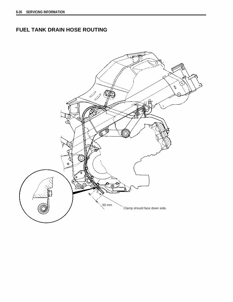
8-26 SERVICING INFORMATION
FUEL TANK DRAIN HOSE ROUTING
50 mmClamp should face down side.
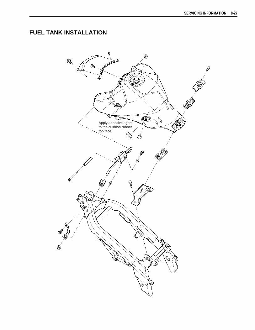
SERVICING INFORMATION 8-27
FUEL TANK INSTALLATION
Apply adhesive agentto the cushion rubbertop face.

8-28 SERVICING INFORMATION
PAIR (AIR SUPPLY) SYSTEM HOSE ROUTINGF
or
Eu
rop
ean
mar
kets
Fo
r U
SA
/CA
NA
DA
/AU
ST
RA
LIA
Mat
chin
g m
ark
(Whi
te)
VIE
W O
F T
OP
SID
E
Mat
chin
g m
ark
(Whi
te)
VIE
W O
F R
IGH
T S
IDE
PAIR
ree
d va
lve
PAIR
val
ve
From
air
clea
ner
10 N
·m(1
.0 k
gf-m
, 7.3
lb-f
t)
Mat
chin
g m
ark
(Yel
low
)
Mat
chin
g m
ark
(Whi
te)
Vac
uum
hos
eM
atch
ing
mar
k(W
hite
)
To th
rottl
e bo
dyV
IEW
OF
TO
P S
IDE
VIE
W O
F R
IGH
T S
IDE
From
air
clea
ner
PAIR
val
vePA
IR r
eed
valv
e
Mat
chin
g m
ark
(Yel
low
)
10 N
·m
(
)1.
0 kg
f-m
7.3
lb-f
t
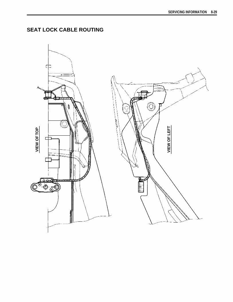
SERVICING INFORMATION 8-29
SEAT LOCK CABLE ROUTING
VIE
W O
F L
EF
T
VIE
W O
F T
OP

8-30 SERVICING INFORMATION
SIDE-STAND SET-UP
BRAKE PEDAL/FOOTREST SET-UP
50 N.m(5.0 kgf-m, 36.0 lb-ft)
40 N.m(4.0 kgf-m, 29.0 lb-ft)
( )100 N.m 10.0 kgf-m 72.5 lb-ft
Brake light switchPin
Footrest
Bracket
E-ring
InsideInsideInsideOutsideOutside
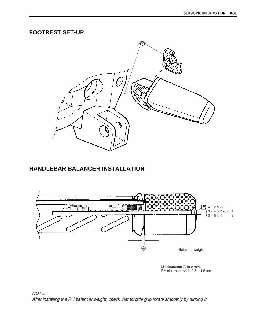
SERVICING INFORMATION 8-31
FOOTREST SET-UP
HANDLEBAR BALANCER INSTALLATION
( )4 – 7 N.m0.4 – 0.7 kgf-m3 – 5 lb-ft
Balancer weight
LH clearance is 0 mm.RH clearance is 0.5 – 1.5 mm.
NOTE:After installing the RH balancer weight, check that throttle grip rotate smoothly by turning it.
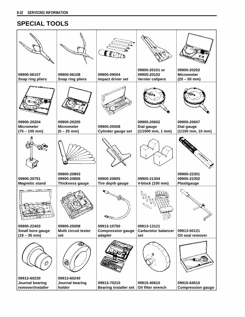
8-32 SERVICING INFORMATION
SPECIAL TOOLS
09900-06107Snap ring pliers
09900-06108Snap ring pliers
09900-09004Impact driver set
09900-20101 or 09900-20102Vernier calipers
09900-20202Micrometer(25 – 50 mm)
09900-20204Micrometer(75 – 100 mm)
09900-20205Micrometer(0 – 25 mm)
09900-20508Cylinder gauge set
09900-20602Dial gauge(1/1000 mm, 1 mm)
09900-20607Dial gauge(1/100 mm, 10 mm)
09900-20701Magnetic stand
09900-2080309900-20806Thickness gauge
09900-20805Tire depth gauge
09900-21304V-block (100 mm)
09900-2230109900-22302Plastigauge
09900-22403Small bore gauge(18 – 35 mm)
09900-25008Multi circuit tester set
09913-10750Compression gauge adapter
09913-13121Carburetor balancer set
09913-50121Oil seal remover
09913-60230Journal bearing remover/installer
09913-60240Journal bearing holder
09913-70210Bearing installer set
09915-40610Oil filter wrench
09915-64510Compression gauge

SERVICING INFORMATION 8-33
09915-72410Oil pressure gauge attachment
09915-74521Oil pressure gauge hose
09915-74532Oil pressure gauge adaptor
09915-77331Meter (for high pres-sure)
09916-10911Valve lapper set
09916-14510Valve spring com-pressor
09916-14910Valve spring com-pressor attachment
09916-21111Valve seat cutter set
09916-24480Solid pilot(N-140-5.5)
Valve seat cutter headSee page 3-42.
09916-34542Reamer handle
09916-34550Valve guide reamer (5.5 mm)
09916-34580Valve guide reamer (10.8 mm)
09916-44910Valve guide remover/installer
09916-53340Attachment
09916-84511Tweezers
09917-47010Vacuum pump gauge
09920-13120Crankcase separat-ing tool
09920-53740Clutch sleeve hub holder
09921-20240Bearing remover set
09922-22711Drive chain cutting and joining tool
09923-73210Bearing remover
09923-74511Bearing puller
09924-74570Final drive gear bearing installer/remover
09924-84510Bearing installer set
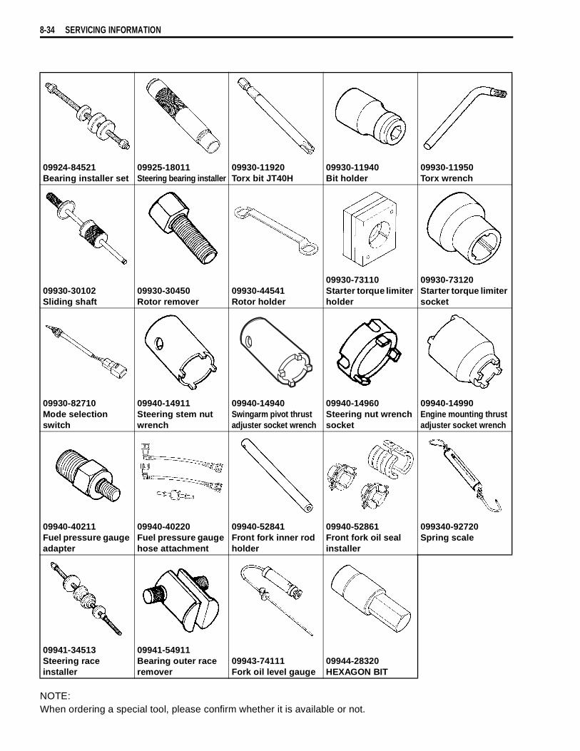
8-34 SERVICING INFORMATION
NOTE:When ordering a special tool, please confirm whether it is available or not.
09924-84521Bearing installer set
09925-18011Steering bearing installer
09930-11920Torx bit JT40H
09930-11940Bit holder
09930-11950Torx wrench
09930-30102Sliding shaft
09930-30450Rotor remover
09930-44541Rotor holder
09930-73110Starter torque limiter holder
09930-73120Starter torque limiter socket
09930-82710Mode selection switch
09940-14911Steering stem nut wrench
09940-14940Swingarm pivot thrust adjuster socket wrench
09940-14960Steering nut wrench socket
09940-14990Engine mounting thrust adjuster socket wrench
09940-40211Fuel pressure gauge adapter
09940-40220Fuel pressure gauge hose attachment
09940-52841Front fork inner rod holder
09940-52861Front fork oil seal installer
099340-92720Spring scale
09941-34513Steering race installer
09941-54911Bearing outer race remover
09943-74111Fork oil level gauge
09944-28320HEXAGON BIT
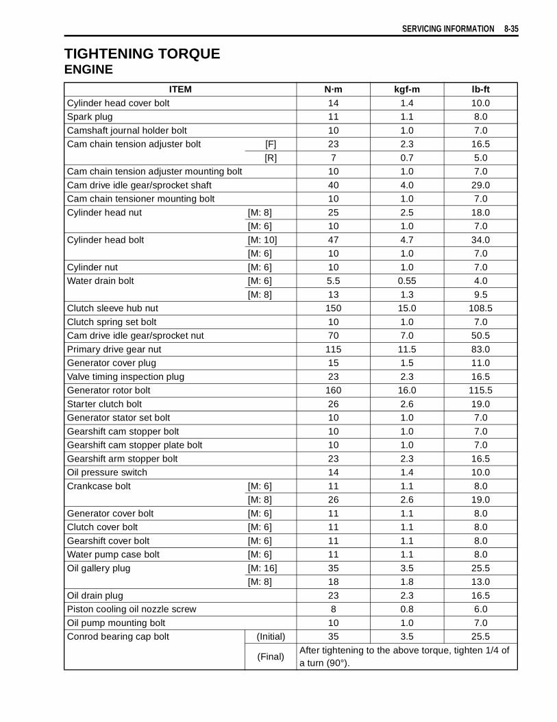
SERVICING INFORMATION 8-35
TIGHTENING TORQUEENGINE
ITEM N·m kgf-m lb-ftCylinder head cover bolt 14 1.4 10.0Spark plug 11 1.1 8.0
Camshaft journal holder bolt 10 1.0 7.0Cam chain tension adjuster bolt [F] 23 2.3 16.5
[R] 7 0.7 5.0Cam chain tension adjuster mounting bolt 10 1.0 7.0
Cam drive idle gear/sprocket shaft 40 4.0 29.0Cam chain tensioner mounting bolt 10 1.0 7.0
Cylinder head nut [M: 8] 25 2.5 18.0[M: 6] 10 1.0 7.0
Cylinder head bolt [M: 10] 47 4.7 34.0[M: 6] 10 1.0 7.0
Cylinder nut [M: 6] 10 1.0 7.0Water drain bolt [M: 6] 5.5 0.55 4.0
[M: 8] 13 1.3 9.5Clutch sleeve hub nut 150 15.0 108.5
Clutch spring set bolt 10 1.0 7.0Cam drive idle gear/sprocket nut 70 7.0 50.5
Primary drive gear nut 115 11.5 83.0Generator cover plug 15 1.5 11.0
Valve timing inspection plug 23 2.3 16.5Generator rotor bolt 160 16.0 115.5
Starter clutch bolt 26 2.6 19.0Generator stator set bolt 10 1.0 7.0
Gearshift cam stopper bolt 10 1.0 7.0Gearshift cam stopper plate bolt 10 1.0 7.0
Gearshift arm stopper bolt 23 2.3 16.5Oil pressure switch 14 1.4 10.0
Crankcase bolt [M: 6] 11 1.1 8.0[M: 8] 26 2.6 19.0
Generator cover bolt [M: 6] 11 1.1 8.0Clutch cover bolt [M: 6] 11 1.1 8.0
Gearshift cover bolt [M: 6] 11 1.1 8.0Water pump case bolt [M: 6] 11 1.1 8.0
Oil gallery plug [M: 16] 35 3.5 25.5[M: 8] 18 1.8 13.0
Oil drain plug 23 2.3 16.5Piston cooling oil nozzle screw 8 0.8 6.0
Oil pump mounting bolt 10 1.0 7.0Conrod bearing cap bolt (Initial) 35 3.5 25.5
(Final)After tightening to the above torque, tighten 1/4 of a turn (90°).
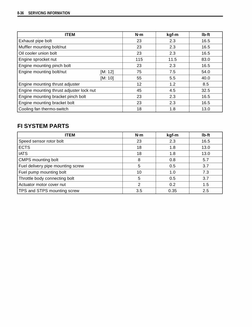
8-36 SERVICING INFORMATION
FI SYSTEM PARTS
ITEM N·m kgf-m lb-ftExhaust pipe bolt 23 2.3 16.5Muffler mounting bolt/nut 23 2.3 16.5
Oil cooler union bolt 23 2.3 16.5Engine sprocket nut 115 11.5 83.0
Engine mounting pinch bolt 23 2.3 16.5Engine mounting bolt/nut [M: 12] 75 7.5 54.0
[M: 10] 55 5.5 40.0Engine mounting thrust adjuster 12 1.2 8.5
Engine mounting thrust adjuster lock nut 45 4.5 32.5Engine mounting bracket pinch bolt 23 2.3 16.5
Engine mounting bracket bolt 23 2.3 16.5Cooling fan thermo-switch 18 1.8 13.0
ITEM N·m kgf-m lb-ftSpeed sensor rotor bolt 23 2.3 16.5
ECTS 18 1.8 13.0IATS 18 1.8 13.0
CMPS mounting bolt 8 0.8 5.7Fuel delivery pipe mounting screw 5 0.5 3.7
Fuel pump mounting bolt 10 1.0 7.3Throttle body connecting bolt 5 0.5 3.7
Actuator motor cover nut 2 0.2 1.5TPS and STPS mounting screw 3.5 0.35 2.5
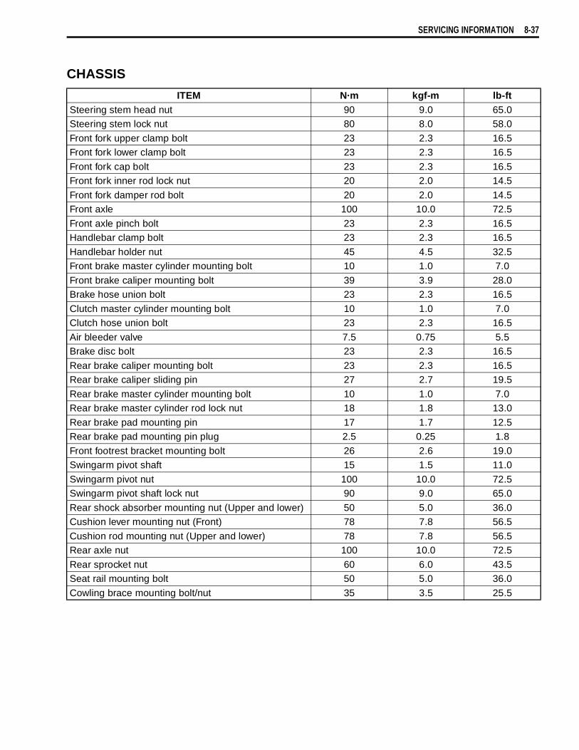
SERVICING INFORMATION 8-37
CHASSIS
ITEM N·m kgf-m lb-ftSteering stem head nut 90 9.0 65.0Steering stem lock nut 80 8.0 58.0
Front fork upper clamp bolt 23 2.3 16.5Front fork lower clamp bolt 23 2.3 16.5
Front fork cap bolt 23 2.3 16.5Front fork inner rod lock nut 20 2.0 14.5
Front fork damper rod bolt 20 2.0 14.5Front axle 100 10.0 72.5
Front axle pinch bolt 23 2.3 16.5Handlebar clamp bolt 23 2.3 16.5
Handlebar holder nut 45 4.5 32.5Front brake master cylinder mounting bolt 10 1.0 7.0
Front brake caliper mounting bolt 39 3.9 28.0Brake hose union bolt 23 2.3 16.5
Clutch master cylinder mounting bolt 10 1.0 7.0Clutch hose union bolt 23 2.3 16.5
Air bleeder valve 7.5 0.75 5.5Brake disc bolt 23 2.3 16.5
Rear brake caliper mounting bolt 23 2.3 16.5Rear brake caliper sliding pin 27 2.7 19.5
Rear brake master cylinder mounting bolt 10 1.0 7.0Rear brake master cylinder rod lock nut 18 1.8 13.0
Rear brake pad mounting pin 17 1.7 12.5Rear brake pad mounting pin plug 2.5 0.25 1.8
Front footrest bracket mounting bolt 26 2.6 19.0Swingarm pivot shaft 15 1.5 11.0
Swingarm pivot nut 100 10.0 72.5Swingarm pivot shaft lock nut 90 9.0 65.0
Rear shock absorber mounting nut (Upper and lower) 50 5.0 36.0Cushion lever mounting nut (Front) 78 7.8 56.5
Cushion rod mounting nut (Upper and lower) 78 7.8 56.5Rear axle nut 100 10.0 72.5
Rear sprocket nut 60 6.0 43.5Seat rail mounting bolt 50 5.0 36.0
Cowling brace mounting bolt/nut 35 3.5 25.5
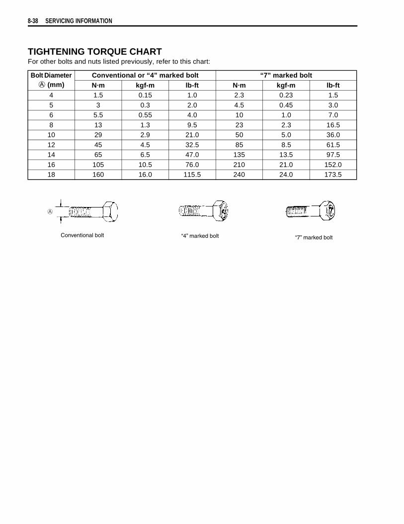
8-38 SERVICING INFORMATION
TIGHTENING TORQUE CHARTFor other bolts and nuts listed previously, refer to this chart:
Bolt Diameter
(mm)Conventional or “4” marked bolt “7” marked boltN·m kgf-m lb-ft N·m kgf-m lb-ft
4 1.5 0.15 1.0 2.3 0.23 1.5
5 3 0.3 2.0 4.5 0.45 3.06 5.5 0.55 4.0 10 1.0 7.0
8 13 1.3 9.5 23 2.3 16.510 29 2.9 21.0 50 5.0 36.0
12 45 4.5 32.5 85 8.5 61.514 65 6.5 47.0 135 13.5 97.5
16 105 10.5 76.0 210 21.0 152.018 160 16.0 115.5 240 24.0 173.5
Conventional bolt “4” marked bolt “7” marked bolt

SERVICING INFORMATION 8-39
SERVICE DATAVALVE + GUIDE Unit: mm (in)
ITEM STANDARD LIMITValve diam. IN. 36
(1.42) —
EX. 33(1.30) —
Tappet clearance (when cold) IN. 0.10 – 0.20(0.004 – 0.008) —
EX. 0.20 – 0.30(0.008 – 0.012) —
Valve guide to valve stem clear-ance IN. 0.010 – 0.037
(0.0004 – 0.0015) —
EX. 0.030 – 0.057(0.0012 – 0.0022) —
Valve guide I.D. IN. & EX. 5.500 – 5.512(0.2165 – 0.2170) —
Valve stem O.D. IN. 5.475 – 5.490(0.2156 – 0.2161) —
EX. 5.455 – 5.470(0.2148 – 0.2154) —
Valve stem deflection IN. & EX. — 0.35(0.014)
Valve stem runout IN. & EX. — 0.05(0.002)
Valve head thickness IN. & EX. — 0.5(0.02)
Valve seat width IN. & EX. 0.9 – 1.1(0.035 – 0.043) —
Valve head radial runout IN. & EX. — 0.03(0.001)
Valve spring free length IN. & EX. — 39.6(1.56)
Valve spring tensionIN. & EX.
197 – 227 N(20.1 – 23.1 kgf, 44.3 – 51.0 lbs)
at length 35.6 mm (1.40 in)—
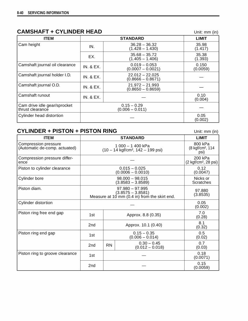
8-40 SERVICING INFORMATION
CAMSHAFT + CYLINDER HEAD Unit: mm (in)
CYLINDER + PISTON + PISTON RING Unit: mm (in)
ITEM STANDARD LIMITCam height IN. 36.28 – 36.32
(1.428 – 1.430)35.98
(1.417)
EX. 35.68 – 35.72(1.405 – 1.406)
35.38(1.393)
Camshaft journal oil clearance IN. & EX. 0.019 – 0.053(0.0007 – 0.0021)
0.150(0.0059)
Camshaft journal holder I.D. IN. & EX. 22.012 – 22.025(0.8666 – 0.8671) —
Camshaft journal O.D. IN. & EX. 21.972 – 21.993(0.8650 – 0.8659) —
Camshaft runout IN. & EX. — 0.10(0.004)
Cam drive idle gear/sprocket thrust clearance
0.15 – 0.29(0.006 – 0.011) —
Cylinder head distortion — 0.05(0.002)
ITEM STANDARD LIMITCompression pressure(Automatic de-comp. actuated) 1 000 – 1 400 kPa
(10 – 14 kgf/cm², 142 – 199 psi)800 kPa
(8 kgf/cm², 114 psi)
Compression pressure differ-ence — 200 kPa
(2 kgf/cm², 28 psi)
Piston to cylinder clearance 0.015 – 0.025(0.0006 – 0.0010)
0.12(0.0047)
Cylinder bore 98.000 – 98.015(3.8583 – 3.8589)
Nicks or Scratches
Piston diam. 97.980 – 97.995(3.8575 – 3.8581)
Measure at 10 mm (0.4 in) from the skirt end.97.880
(3.8535)
Cylinder distortion — 0.05(0.002)
Piston ring free end gap 1st Approx. 8.8 (0.35) 7.0(0.28)
2nd Approx. 10.1 (0.40) 8.1(0.32)
Piston ring end gap 1st 0.15 – 0.35(0.006 – 0.014)
0.5(0.02)
2nd RN 0.30 – 0.45(0.012 – 0.018)
0.7(0.03)
Piston ring to groove clearance 1st — 0.18(0.0071)
2nd — 0.15(0.0059)
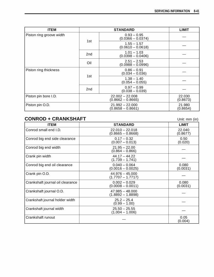
SERVICING INFORMATION 8-41
CONROD + CRANKSHAFT Unit: mm (in)
ITEM STANDARD LIMITPiston ring groove width
1st
0.93 – 0.95(0.0366 – 0.0374) —
1.55 – 1.57(0.0610 – 0.0618) —
2nd 1.01 – 1.03(0.0398 – 0.0406) —
Oil 2.51 – 2.53(0.0988 – 0.0996) —
Piston ring thickness
1st
0.86 – 0.91(0.034 – 0.036) —
1.38 – 1.40(0.054 – 0.055) —
2nd 0.97 – 0.99(0.038 – 0.039) —
Piston pin bore I.D. 22.002 – 22.008(0.8662 – 0.8665)
22.030(0.8673)
Piston pin O.D. 21.992 – 22.000(0.8658 – 0.8661)
21.980(0.8654)
ITEM STANDARD LIMITConrod small end I.D. 22.010 – 22.018
(0.8665 – 0.8668)22.040
(0.8677)Conrod big end side clearance 0.17 – 0.32
(0.007 – 0.013)0.50
(0.020)
Conrod big end width 21.95 – 22.00(0.864 – 0.866) —
Crank pin width 44.17 – 44.22(1.739 – 1.741) —
Conrod big end oil clearance 0.040 – 0.064(0.0016 – 0.0025)
0.080(0.0031)
Crank pin O.D. 44.976 – 45.000(1.7707 – 1.7717) —
Crankshaft journal oil clearance 0.002 – 0.029(0.0008 – 0.0011)
0.080(0.0031)
Crankshaft journal O.D. 47.985 – 48.000(1.8892 – 1.8898) —
Crankshaft journal holder width 25.2 – 25.4(0.99 – 1.00) —
Crankshaft journal width 25.50 – 25.55(1.004 – 1.006) —
Crankshaft runout — 0.05(0.004)

8-42 SERVICING INFORMATION
OIL PUMP
CLUTCH Unit: mm (in)
THERMOSTAT + RADIATOR + FAN
ITEM STANDARD LIMITOil pressure (at 60°C, 140°F) Above 400 kPa (4.0 kgf/cm2, 57 psi)
Below 700 kPa (7.0 kgf/cm2, 100 psi)at 3 000 r/min.
—
ITEM STANDARD LIMITDrive plate thickness No.1 2.92 – 3.08
(0.115 – 0.121)2.62
(0.103)
No.2 and 3 3.72 – 3.88(0.146 – 0.153)
3.42(0.135)
Drive plate claw width No.1 13.85 – 13.96(0.545 – 0.550)
13.05(0.514)
No.2 and 3 13.90 – 14.00(0.547 – 0.551)
13.10(0.516)
Driven plate distortion — 0.10(0.004)
Clutch spring free length 61.5 – 62.5(2.42 – 2.46)
59.4(2.34)
Clutch master cylinder bore 14.000 – 14.043(0.5512 – 0.5528) —
Clutch master cylinder piston diam.
13.957 – 13.984(0.5495 – 0.5505) —
Clutch release cylinder bore 35.700 – 35.762(1.4055 – 1.4079) —
Clutch release cylinder piston diam.
35.650 – 35.675(1.4035 – 1.4045) —
ITEM STANDARD LIMITThermostat valve opening tem-perature
86.5 – 89.5 °C(188 – 193 °F) —
Thermostat valve lift Over 8 mm (0.31 in) at 100 °C (212 °F) —
Radiator cap valve opening pressure 110 kPa (1.1 kgf/cm², 15.6 psi) —
Cooling fan ther-moswitch operating temperature
OFF→ON Approx. 105 °C (221°F) —
ON→OFF Approx. 100 °C (212°F) —
Engine coolant tem-perature sensor resistance
20 °C(68 °F) Approx. 2.45 kΩ —
40 °C(104 °F) Approx. 1.148 kΩ —
60 °C(140 °F) Approx. 0.587 kΩ —
80 °C(176 °F) Approx. 0.322 kΩ —

SERVICING INFORMATION 8-43
DRIVE TRAIN Unit: mm (in) Expect ratio
INJECTOR + FUEL PUMP + FUEL PRESSURE REGURATOR
ITEM STANDARD LIMITPrimary reduction ratio 1.838 (57/31) —Final reduction ratio 2.411 (41/17) —
Gear ratio Low 3.000 (36/12) —2nd 1.933 (29/15) —
3rd 1.500 (27/18) —4th 1.227 (27/22) —
5th 1.086 (25/23) —Top 0.913 (21/23) —
Shift fork to groove clearance 0.1 – 0.3(0.004 – 0.012)
0.50(0.020)
Shift fork groove width 5.0 – 5.1(0.197 – 0.201) —
Shift fork thickness 4.8 – 4.9(0.189 – 0.193) —
Drive chain Type RK525SMOZ7 —
Links 112 links, ENDLESS —
20-pitch length — 319.4(12.6)
Drive chain slack 20 – 30(0.8 – 1.2) —
Gearshift lever height 25(1.0) —
ITEM SPECIFICATION NOTEInjector resistance 12 – 18 Ω at 20 °C (68°F)Fuel pump discharge amount Approx. 1.2 L (1.3/1.1 US/lmp qt)
for 60 seconds at 300 kPa (3.0 kgf/cm², 43 psi)Fuel pressure regulator operat-ing set pressure Approx. 300 kPa (3.0 kgf/cm², 43 psi)

8-44 SERVICING INFORMATION
FI-SENSORS
THROTTLE BODY
ITEM SPECIFICATION NOTECMP sensor peak voltage More than 3.7 VCKP sensor resistance 130 – 240 ΩCKP sensor peak voltage More than 3.7 V (When cranking)IAP sensor input voltage 4.5 – 5.5 V
IAP sensor output voltage Approx. 2.5 V at idle speedTP sensor input voltage 4.5 – 5.5 V
TP sensor resistance Closed Approx. 1.1 kΩOpened Approx. 4.3 kΩ
TP sensor output voltage Closed Approx. 1.1 VOpened Approx. 4.3 V
ECT sensor input voltage 4.5 – 5.5 VECT sensor reisitance Approx. 2.45 kΩ at 20 °C (68°F)
IAT sensor input volatage 4.5 – 5.5 VIAT sensor resistance Approx 2.45 kΩ at 20 °C (68°F)
AP sensor input voltage 4.5 – 5.5 VAP sensor output voltage Approx. 4.0 V at 760 mmHg (100kPa)
TO sensor resistance 19.1 – 19.7 kΩTO sensor voltage Approx. 0.4 – 1.4 V
GP switch voltage More than 1.0 V (From 1st to top)Injector voltage Battery voltage
Ignition coil primary peak volt-age More than 150 V (When cranking)
STP sensor input voltage 4.5 – 5.5 VSTP sensor resistance Closed Approx. 1.1 kΩ
Opened Approx. 4.3 kΩSTP sensor output voltage Closed Approx. 1.1 V
Opened Approx. 4.3 VSTV actuator resistance 4.8 – 7.2 ΩHeated oxygen sensor output voltage
less than 0.4 V at idle speed(After warming up)
European marketsHeated oxygen sensor resis-
tance 4 – 5 Ω at 23 °C (73.4 °F)
PAIR solenoid valve resistance 20 – 24 Ω at 20 °C (68 °F)
ITEM SPECIFICATIONID No. 06G0 (For E-02, 19), 06G1 (For E-33), 06G2 (For E-03, 24, 28)
Bore size 45 mmFast idle r/min 1 500 – 2 100 r/min at 25 °C (77 °F)
Idle r/min 1 200 ± 100 r/min/Warmed engineThrottle cable play 2.0 – 4.0 r/min
(0.08 – 0.16 in)

SERVICING INFORMATION 8-45
ELECTRICAL Unit: mm (in)
ITEM SPECIFICATION NOTEIgnition timing 4° B.T.D.C. at 1 200 r/minFiring order 1·2
Spark plug Type NGK: CR8EKDenso: U24ETR
Gap 0.6 – 0.7(0.024 – 0.028)
Spark performance Over 8 (0.3) at 1 atm.
Crankshaft position sensor resistance 130 – 240 Ω Bl – G
Ignition coil resistance Primary 2 – 5 Ω
tap –
tapSecondary 24 – 37 kΩ
tap – Plug cap
Crankshaft position sensor peak voltage More than 3.7 V When cranking
Ignition coil primary peak volt-age More than 150 V When cranking
Generator coil resistance 0.2 – 0.5 Ω Y – Y
Generator Max. output Approx. 350 W at 5 000 r/minGenerator no-load voltage(When engine is cold) More than 75 V (AC) at 5 000 r/min
Regulated voltage 14.0 – 15.5 V at 5 000 r/min
Starter relay resistance 3 – 6 ΩBattery Type
designation FTX14-BS
Capacity 12 V 43.2 kC (12 Ah)/10 HR
Fuze sizeHeadlight
HI 15 ALO 15 A
Turn signal 15 AIgnition 15 A
Fan motor 15 AMeter 10 A
Main 30 A
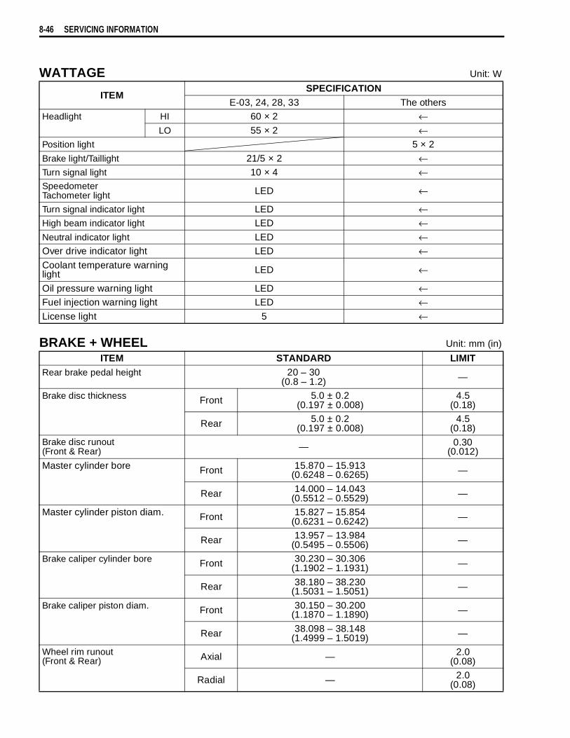
8-46 SERVICING INFORMATION
WATTAGE Unit: W
BRAKE + WHEEL Unit: mm (in)
ITEMSPECIFICATION
E-03, 24, 28, 33 The othersHeadlight HI 60 × 2 ←
LO 55 × 2 ←Position light 5 × 2
Brake light/Taillight 21/5 × 2 ←Turn signal light 10 × 4 ←SpeedometerTachometer light LED ←
Turn signal indicator light LED ←High beam indicator light LED ←Neutral indicator light LED ←Over drive indicator light LED ←Coolant temperature warning light LED ←
Oil pressure warning light LED ←Fuel injection warning light LED ←License light 5 ←
ITEM STANDARD LIMITRear brake pedal height 20 – 30
(0.8 – 1.2) —
Brake disc thickness Front 5.0 ± 0.2(0.197 ± 0.008)
4.5(0.18)
Rear 5.0 ± 0.2(0.197 ± 0.008)
4.5(0.18)
Brake disc runout(Front & Rear) — 0.30
(0.012)
Master cylinder bore Front 15.870 – 15.913(0.6248 – 0.6265) —
Rear 14.000 – 14.043(0.5512 – 0.5529) —
Master cylinder piston diam. Front 15.827 – 15.854(0.6231 – 0.6242) —
Rear 13.957 – 13.984(0.5495 – 0.5506) —
Brake caliper cylinder bore Front 30.230 – 30.306(1.1902 – 1.1931) —
Rear 38.180 – 38.230(1.5031 – 1.5051) —
Brake caliper piston diam. Front 30.150 – 30.200(1.1870 – 1.1890) —
Rear 38.098 – 38.148(1.4999 – 1.5019) —
Wheel rim runout(Front & Rear) Axial — 2.0
(0.08)
Radial — 2.0(0.08)

SERVICING INFORMATION 8-47
)
SUSPENSION Unit: mm (in)
TIRE PRESSURE
ITEM STANDARD LIMITWheel axle runout Front — 0.25
(0.010)
Rear — 0.25(0.010)
Wheel rim size Front 19M/C × MT 2.50 —
Rear 17M/C × MT 4.00 —Tire size Front 110/80R19M/C 59H —
Rear 150/70R17M/C 69H —Tire type Front BRIDGESTONE: TW101 F —
Rear BRIDGESTONE: TW152 F —Tire tread depth Front — 1.6
(0.06)
Rear — 2.0(0.08)
ITEM STANDARD LIMITFront fork stroke 160
(6.3) —
Front fork spring free length — 442(17.4)
Front fork oil level (without spring, inner tube fully compressed)
133.0(5.24) —
Rear shock absorber spring adjuster 2nd groove from bottom —
Rear shock absorber damping force adjuster Rebound turn out from stiffest position —
Rear wheel travel 159(6.3) —
Swingarm pivot shaft runput — 0.3(0.01)
COLD INFLATIONTIRE PRESSURE
SOLO RIDING DUAL RIDING
kPa kgf/cm² psi kPa kgf/cm² psi
FRONT 250 2.50 36 250 2.50 36REAR 250 2.50 36 280 2.80 41

8-48 SERVICING INFORMATION
FUEL + OIL + ENGINE COOLANTITEM SPECIFICATION NOTE
Fuel type Use only unleaded gasoline of at least 87 pump octane ( ) or 91 octane or higher rated by the research method. Gasoline containing MTBE (Methyl Tertiary Butyl Ether), less than 10% ethanol, or less than 5% methanol with appropriate cosolvents and corrosion inhibitor is permissible.
E-03, 28, 33
Gasoline used should be graded 91 octane or higher. An unleaded gasoline is recommended.
The others
Fuel tank 17L(4.5/3.7 US/lmp gal)
Engine oil type SAE 10W/40, API SF or SGEngine oil capacity Change 2 700 ml
(2.9/2.4 US/lmp qt)
Filter change 2 900 ml(3.1/2.6 US/lmp qt)
Overhaul 3 300 ml(3.5/2.9 US/lmp qt)
Front fork oil type SUZUKI FORK OIL SS-08 or an equivalent fork oilFront fork oil capacity (each leg) 505.0 ml
(17.07/17.78 US/lmp oz)
Brake fluid type DOT 4Engine coolant type Use an anti-freeze/coolant compatible with aluminum
radiator, mixed with distilled water only, at the ratio of 50:50.
Engien coolant Reserve tank side
Approx. 250 ml(0.3/0.2 US/lmp qt)
Engine side Approx. 1 950 ml(2.1/1.7 US/lmp qt)
2R + M
9
EMISSION CONTROL INFORMATION 9-1
CONTENTS
EMISSION CONTROL INFORMATION
EMISSION CONTROL SYSTEMS ......................................................9- 2
FUEL INJECTION SYSTEM ........................................................9- 2
CRANKCASE EMISSION CONTROL SYSTEM ..........................9- 3
EXHAUST EMISSION CONTROL SYSTEM (PAIR SYSTEM) ....9- 4
NOISE EMISSION CONTROL SYSTEM .....................................9- 5
EVAPORATIVE EMISSION CONTROL SYSTEM
(Only for E-33) .............................................................................9- 5
PAIR (AIR SUPPLY) SYSTEM INSPECTION ....................................9- 6
PAIR (AIR SUPPLY) SYSTEM HOSE ROUTING ..............................9- 8
HEATED OXGEN SENSOR (HO2S) INSPECTION ............................9- 9
HEATED OXGEN SENSOR WIRE ROUTING ....................................9-10
EVAPORATIVE EMISSION CONTROL SYSTEM INSPECTION
(Only for E-33) ....................................................................................9-11
CANISTER HOSE ROUTING (Only for E-33) ....................................9-12

9-2 EMISSION CONTROL INFORMATION
EMISSION CONTROL SYSTEMSFUEL INJECTION SYSTEMDL1000 motorcycles are equipped with a fuel injection system for emission level control.This fuel injection system is precision designed, manufactured and adjusted to comply with the applicableemission limits.
Fuel pressureregulator
Fuel pump
Fuel mesh filter(For low pressure)
Fuel feed hoseFuel injector
Fuel filter(For high pressure)
BEFORE-PRESSURIZEDFUEL
RELIEVED FUEL
PRESSURIZED FUEL

EMISSION CONTROL INFORMATION 9-3
CRANKCASE EMISSION CONTROL SYSTEMThe engine is equipped with a PCV system. Blow-by gas in the engine is constantly drawn into the crank-case, which is returned to the combustion chamber through the breather hose, air cleaner and throttle body.
Breather hose
FRESH AIR
FUEL/AIR MIXTURE
BLOW-BY GAS

9-4 EMISSION CONTROL INFORMATION
EXHAUST EMISSION CONTROL SYSTEM (PAIR SYSTEM)The exhaust emission control system is composed of the PAIR system and THREE-WAY CATALYST sys-tem. The fresh air is drawn into the exhaust port with the PAIR solenoid valve and PAIR reed valve. ThePAIR solenoid valve is operated by the ECM, and the fresh air flow is controlled according to the TPS,ECTS, IATS, IAPS and CKPS.
ECM
Three-waycatalyst
PAIR reed valve
HO2 sensor
PAIR control solenoid valve
FRESH AIR
EXHAUST GAS
PAIRreed valve
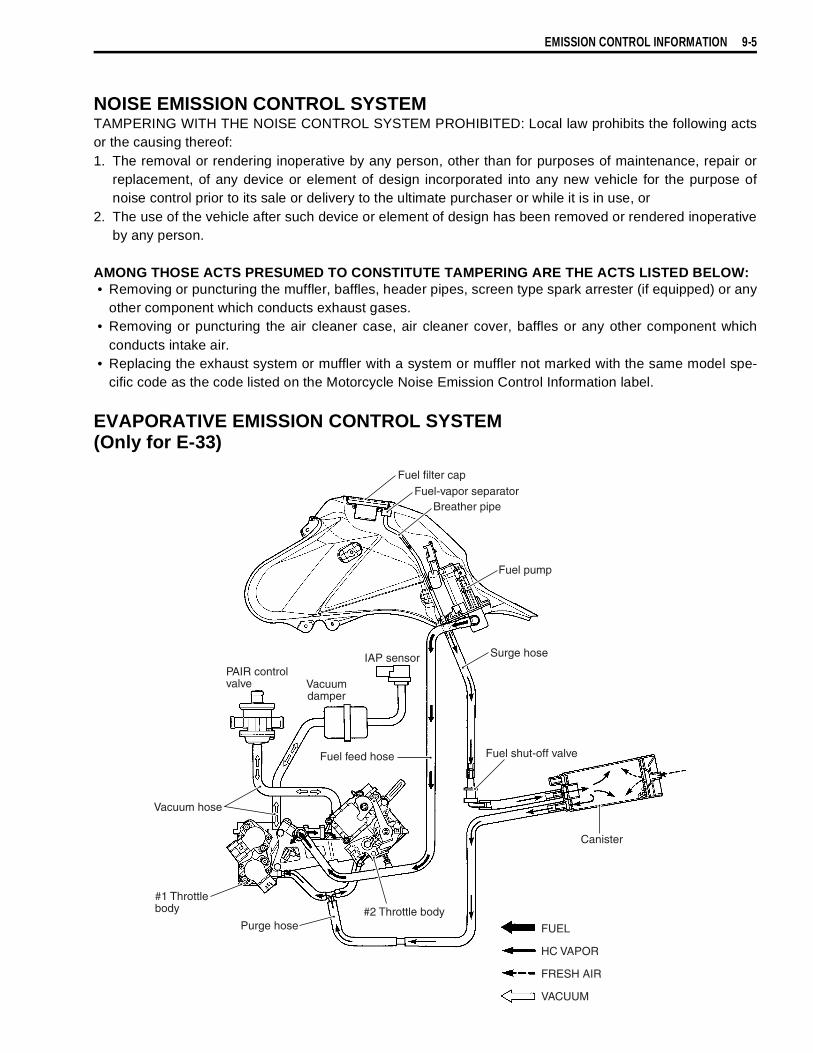
EMISSION CONTROL INFORMATION 9-5
NOISE EMISSION CONTROL SYSTEMTAMPERING WITH THE NOISE CONTROL SYSTEM PROHIBITED: Local law prohibits the following actsor the causing thereof:1. The removal or rendering inoperative by any person, other than for purposes of maintenance, repair or
replacement, of any device or element of design incorporated into any new vehicle for the purpose ofnoise control prior to its sale or delivery to the ultimate purchaser or while it is in use, or
2. The use of the vehicle after such device or element of design has been removed or rendered inoperativeby any person.
AMONG THOSE ACTS PRESUMED TO CONSTITUTE TAMPERING ARE THE ACTS LISTED BELOW:• Removing or puncturing the muffler, baffles, header pipes, screen type spark arrester (if equipped) or any
other component which conducts exhaust gases.• Removing or puncturing the air cleaner case, air cleaner cover, baffles or any other component which
conducts intake air.• Replacing the exhaust system or muffler with a system or muffler not marked with the same model spe-
cific code as the code listed on the Motorcycle Noise Emission Control Information label.
EVAPORATIVE EMISSION CONTROL SYSTEM (Only for E-33)
Fuel filter capFuel-vapor separator
Breather pipe
Fuel pump
Fuel feed hose
Surge hose
Fuel shut-off valve
Canister
FUEL
HC VAPOR
FRESH AIR
VACUUM
#2 Throttle body#1 Throttlebody
Purge hose
Vacuum hose
PAIR controlvalve Vacuum
damper
IAP sensor
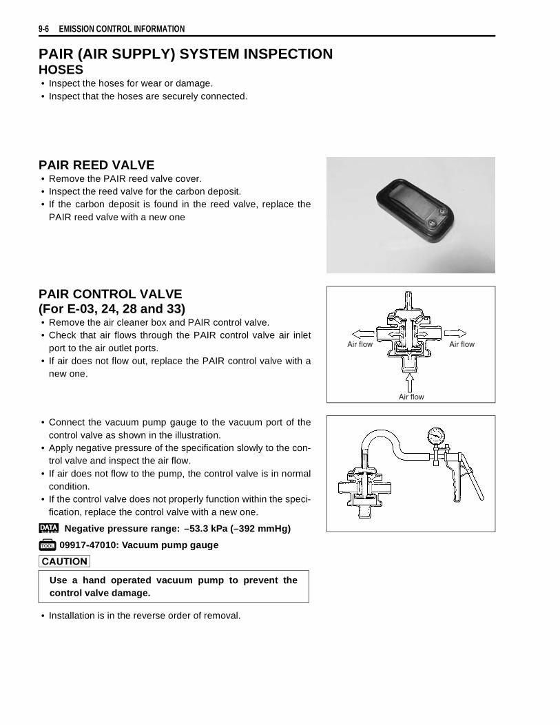
9-6 EMISSION CONTROL INFORMATION
PAIR (AIR SUPPLY) SYSTEM INSPECTIONHOSES• Inspect the hoses for wear or damage.• Inspect that the hoses are securely connected.
PAIR REED VALVE• Remove the PAIR reed valve cover.• Inspect the reed valve for the carbon deposit.• If the carbon deposit is found in the reed valve, replace the
PAIR reed valve with a new one
PAIR CONTROL VALVE(For E-03, 24, 28 and 33)• Remove the air cleaner box and PAIR control valve.• Check that air flows through the PAIR control valve air inlet
port to the air outlet ports.• If air does not flow out, replace the PAIR control valve with a
new one.
• Connect the vacuum pump gauge to the vacuum port of thecontrol valve as shown in the illustration.
• Apply negative pressure of the specification slowly to the con-trol valve and inspect the air flow.
• If air does not flow to the pump, the control valve is in normalcondition.
• If the control valve does not properly function within the speci-fication, replace the control valve with a new one.
Negative pressure range: –53.3 kPa (–392 mmHg)
09917-47010: Vacuum pump gauge
• Installation is in the reverse order of removal.
Air flow Air flow
Air flow
Use a hand operated vacuum pump to prevent thecontrol valve damage.
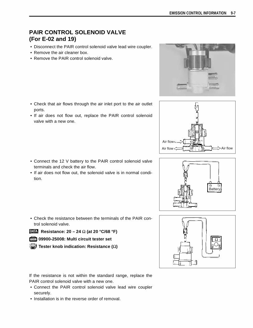
EMISSION CONTROL INFORMATION 9-7
PAIR CONTROL SOLENOID VALVE(For E-02 and 19)• Disconnect the PAIR control solenoid valve lead wire coupler.• Remove the air cleaner box.• Remove the PAIR control solenoid valve.
• Check that air flows through the air inlet port to the air outletports.
• If air does not flow out, replace the PAIR control solenoidvalve with a new one.
• Connect the 12 V battery to the PAIR control solenoid valveterminals and check the air flow.
• If air does not flow out, the solenoid valve is in normal condi-tion.
• Check the resistance between the terminals of the PAIR con-trol solenoid valve.
Resistance: 20 – 24 Ω (at 20 °C/68 °F)
09900-25008: Multi circuit tester set
Tester knob indication: Resistance (Ω)
If the resistance is not within the standard range, replace thePAIR control solenoid valve with a new one.• Connect the PAIR control solenoid valve lead wire coupler
securely.• Installation is in the reverse order of removal.
Air flow
Air flow Air flow
Battery
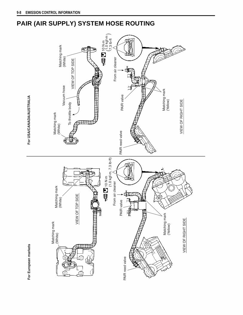
9-8 EMISSION CONTROL INFORMATION
PAIR (AIR SUPPLY) SYSTEM HOSE ROUTINGF
or
Eu
rop
ean
mar
kets
Fo
r U
SA
/CA
NA
DA
/AU
ST
RA
LIA
Mat
chin
g m
ark
(Whi
te)
VIE
W O
F T
OP
SID
E
Mat
chin
g m
ark
(Whi
te)
VIE
W O
F R
IGH
T S
IDE
PAIR
ree
d va
lve
PAIR
val
ve
From
air
clea
ner
10 N
·m(1
.0 k
gf-m
, 7.3
lb-f
t)
Mat
chin
g m
ark
(Yel
low
)
Mat
chin
g m
ark
(Whi
te)
Vac
uum
hos
eM
atch
ing
mar
k(W
hite
)
To th
rottl
e bo
dyV
IEW
OF
TO
P S
IDE
VIE
W O
F R
IGH
T S
IDE
From
air
clea
ner
PAIR
val
vePA
IR r
eed
valv
e
Mat
chin
g m
ark
(Yel
low
)
10 N
·m
(
)1.
0 kg
f-m
7.3
lb-f
t
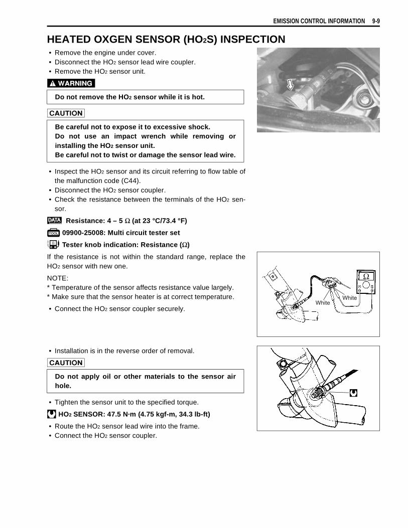
EMISSION CONTROL INFORMATION 9-9
HEATED OXGEN SENSOR (HO2S) INSPECTION• Remove the engine under cover.• Disconnect the HO2 sensor lead wire coupler.• Remove the HO2 sensor unit.
• Inspect the HO2 sensor and its circuit referring to flow table ofthe malfunction code (C44).
• Disconnect the HO2 sensor coupler.• Check the resistance between the terminals of the HO2 sen-
sor.
Resistance: 4 – 5 Ω (at 23 °C/73.4 °F)
09900-25008: Multi circuit tester set
Tester knob indication: Resistance (Ω)
If the resistance is not within the standard range, replace theHO2 sensor with new one.
NOTE:* Temperature of the sensor affects resistance value largely.* Make sure that the sensor heater is at correct temperature.
• Connect the HO2 sensor coupler securely.
• Installation is in the reverse order of removal.
• Tighten the sensor unit to the specified torque.
HO2 SENSOR: 47.5 N·m (4.75 kgf-m, 34.3 lb-ft)
• Route the HO2 sensor lead wire into the frame.• Connect the HO2 sensor coupler.
Do not remove the HO2 sensor while it is hot.
Be careful not to expose it to excessive shock.Do not use an impact wrench while removing orinstalling the HO2 sensor unit.Be careful not to twist or damage the sensor lead wire.
WhiteWhite
Do not apply oil or other materials to the sensor airhole.
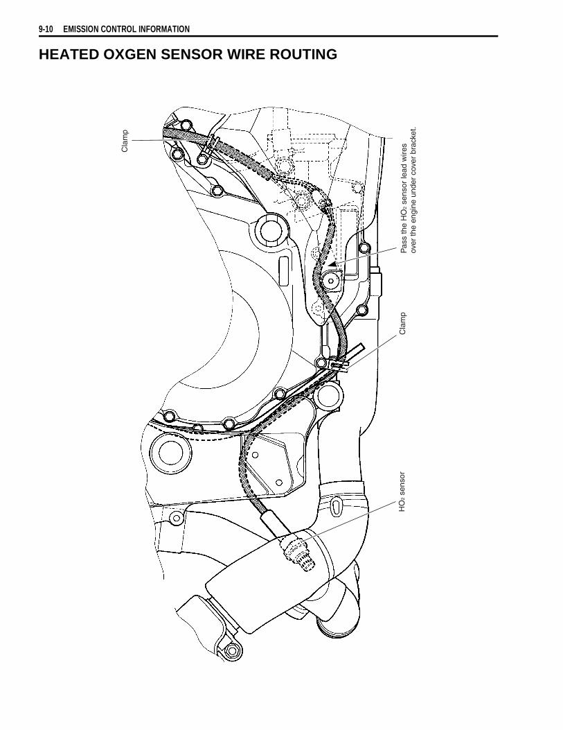
9-10 EMISSION CONTROL INFORMATION
HEATED OXGEN SENSOR WIRE ROUTING
Cla
mp
HO
2 se
nsor
Pas
s th
e H
O2
sens
or le
ad w
ires
over
the
engi
ne u
nder
cov
er b
rack
et.
Cla
mp
EMISSION CONTROL INFORMATION 9-11
EVAPORATIVE EMISSION CONTROL SYSTEM INSPECTION(Only for E-33)• Remove the seat and frame cover.• Remove the fuel tank. ( 4-56)
HOSESInspect the hoses for wear or damage.Make sure that the hoses are securely connected.
CANISTERInspect the canister for damage to the body.

9-12 EMISSION CONTROL INFORMATION
CANISTER HOSE ROUTING (Only for E-33)
Fuel shut-off valve
Chacoal canister
Chacoalcanister
Set the hoseto the hook of the rear fender.
To throttle body
Wiring harness
Purge hose
Purge hose
White paint mark faces top side.
Frame
Rear fender
Inside.
Clamp ends should face........ .
Down side.
Wiring harness
Outside.
Surge hose
Surge hose

10
DL1000K3 (’03-MODEL) 10-1
CONTENTS
DL1000K3 (’03-MODEL)
This chapter describes service specifications, service data and servicing procedures which dif-fer from those of the DL1000K2 (’02-MODEL).
NOTE:* Any differences between the DL1000K2 (’02-model) and DL1000K3 (’03-model) in specifica-
tions and service data are indicated with an asterisk mark (*).* Please refer to the chapters 1 through 9 for details which are not given in this chapter.
SPECIFICATIONS .......................................................................................10- 2
SERVICE DATA ...........................................................................................10- 4FRONT FORK ..............................................................................................10-14
REGULATOR/RECTIFIER INSPECTION ....................................................10-15
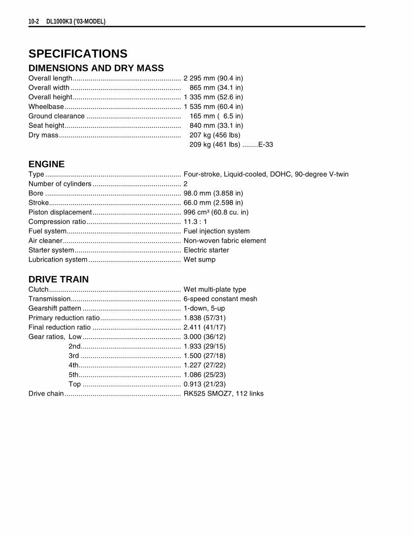
10-2 DL1000K3 (’03-MODEL)
SPECIFICATIONSDIMENSIONS AND DRY MASSOverall length....................................................... 2 295 mm (90.4 in)Overall width ........................................................ 865 mm (34.1 in)Overall height....................................................... 1 335 mm (52.6 in)Wheelbase........................................................... 1 535 mm (60.4 in)Ground clearance ................................................ 165 mm ( 6.5 in)Seat height........................................................... 840 mm (33.1 in)Dry mass.............................................................. 207 kg (456 lbs)
209 kg (461 lbs) ........E-33
ENGINEType ..................................................................... Four-stroke, Liquid-cooled, DOHC, 90-degree V-twinNumber of cylinders ............................................. 2Bore ..................................................................... 98.0 mm (3.858 in)Stroke................................................................... 66.0 mm (2.598 in)Piston displacement............................................. 996 cm³ (60.8 cu. in)Compression ratio................................................ 11.3 : 1Fuel system.......................................................... Fuel injection systemAir cleaner............................................................ Non-woven fabric elementStarter system...................................................... Electric starterLubrication system ............................................... Wet sump
DRIVE TRAINClutch................................................................... Wet multi-plate typeTransmission........................................................ 6-speed constant meshGearshift pattern .................................................. 1-down, 5-upPrimary reduction ratio......................................... 1.838 (57/31)Final reduction ratio ............................................. 2.411 (41/17)Gear ratios, Low .................................................. 3.000 (36/12)
2nd................................................... 1.933 (29/15)3rd ................................................... 1.500 (27/18)4th.................................................... 1.227 (27/22)5th.................................................... 1.086 (25/23)Top .................................................. 0.913 (21/23)
Drive chain ........................................................... RK525 SMOZ7, 112 links

DL1000K3 (’03-MODEL) 10-3
CHASSISFront suspension................................................. Inverted telescopic, coil spring, oil dampedRear suspension ................................................. Link type, coil spring, oil dampedSteering angle ..................................................... 40° (right & left)Caster.................................................................. 26° 30’Trail ..................................................................... 111 mm (4.3 in)Turning radius ..................................................... 2.7 m (8.86 ft)Front brake.......................................................... Disc brake, twinRear brake .......................................................... Disc brakeFront tire size ...................................................... 110/80 R19M/C 59H, tubelessRear tire size ....................................................... 150/70 R17M/C 69H, tubelessFront fork stroke .................................................. 160 mm (6.3 in)Rear wheel travel ................................................ 159 mm (6.2 in)
ELECTRICAL lgnition type ......................................................... Electronic ignition (ECM, Transistorized)lgnition timing ...................................................... 4° B.T.D.C at 1 200 r/minSpark plug ........................................................... NGK: CR8EK or DENSO: U24ETRBattery................................................................. 12 V 43.2 kC (12 Ah)/10 HRGenerator ............................................................ Three-phase A.C. GeneratorFuse .................................................................... 30/15/15/15/15/15/10 AHeadlight ............................................................. 12 V 60/55 W H4Position light........................................................ 12 V 5 W × 2.........Except for E-03, 24, 28, 33Turn signal/Hazard light ...................................... 12 V 10 WLicense light ........................................................ 12 V 5 WBrake light/Taillight .............................................. 12 V 21/5 W × 2Speedometer/Tachometer light........................... LEDNeutral indicator light .......................................... LEDHigh beam indicator light..................................... LEDTurn signal indicator light .................................... LEDOver drive indicator light ..................................... LEDFuel injector warning light ................................... LEDEngine coolant temperature warning light........... LEDOil pressure warning light.................................... LED
CAPACITIES Fuel tank ............................................................. 22 L (5.8/4.8 US/Imp gal)Engine oil, oil change ........................................ 2 700 ml (2.9/2.4 US/Imp qt)
with filter change.............................. 2 900 ml (3.1/2.6 US/Imp qt)overhaul ........................................... 3 300 ml (3.5/2.9 US/Imp qt)
Engine coolant, including reserve ....................... 2 200 ml (2.3/1.9 US/Imp oz)Front fork oil (each leg) ....................................... 505 ml (17.1/17.8 US/Imp oz)
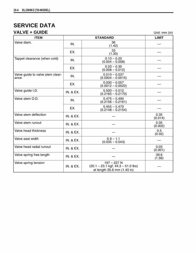
10-4 DL1000K3 (’03-MODEL)
SERVICE DATAVALVE + GUIDE Unit: mm (in)
ITEM STANDARD LIMITValve diam. IN. 36
(1.42) —
EX. 33(1.30) —
Tappet clearance (when cold) IN. 0.10 – 0.20(0.004 – 0.008) —
EX. 0.20 – 0.30(0.008 – 0.012) —
Valve guide to valve stem clear-ance IN. 0.010 – 0.037
(0.0004 – 0.0015) —
EX. 0.030 – 0.057(0.0012 – 0.0022) —
Valve guide I.D. IN. & EX. 5.500 – 5.512(0.2165 – 0.2170) —
Valve stem O.D. IN. 5.475 – 5.490(0.2156 – 0.2161) —
EX. 5.455 – 5.470(0.2148 – 0.2154) —
Valve stem deflection IN. & EX. — 0.35(0.014)
Valve stem runout IN. & EX. — 0.05(0.002)
Valve head thickness IN. & EX. — 0.5(0.02)
Valve seat width IN. & EX. 0.9 – 1.1(0.035 – 0.043) —
Valve head radial runout IN. & EX. — 0.03(0.001)
Valve spring free length IN. & EX. — 39.6(1.56)
Valve spring tensionIN. & EX.
197 – 227 N(20.1 – 23.1 kgf, 44.3 – 51.0 lbs)
at length 35.6 mm (1.40 in)—

DL1000K3 (’03-MODEL) 10-5
CAMSHAFT + CYLINDER HEAD Unit: mm (in)
CYLINDER + PISTON + PISTON RING Unit: mm (in)
ITEM STANDARD LIMITCam height IN. 36.28 – 36.32
(1.428 – 1.430)35.98
(1.417)
EX. 35.68 – 35.72(1.405 – 1.406)
35.38(1.393)
Camshaft journal oil clearance IN. & EX. 0.019 – 0.053(0.0007 – 0.0021)
0.150(0.0059)
Camshaft journal holder I.D. IN. & EX. 22.012 – 22.025(0.8666 – 0.8671) —
Camshaft journal O.D. IN. & EX. 21.972 – 21.993(0.8650 – 0.8659) —
Camshaft runout IN. & EX. — 0.10(0.004)
Cam drive idle gear/sprocket thrust clearance
0.15 – 0.29(0.006 – 0.011) —
Cylinder head distortion — 0.05(0.002)
ITEM STANDARD LIMITCompression pressure(Automatic de-comp. actuated)
1 000 – 1 400 kPa(10 – 14 kgf/cm², 142 – 199 psi)
800 kPa(8 kgf/cm², 114 psi)
Compression pressure differ-ence — 200 kPa
(2 kgf/cm², 28 psi)
Piston to cylinder clearance 0.015 – 0.025(0.0006 – 0.0010)
0.12(0.0047)
Cylinder bore 98.000 – 98.015(3.8583 – 3.8589)
Nicks or Scratches
Piston diam. 97.980 – 97.995(3.8575 – 3.8581)
Measure at 10 mm (0.4 in) from the skirt end.
97.880(3.8535)
Cylinder distortion — 0.05(0.002)
Piston ring free end gap 1st Approx. 8.8 (0.35) 7.0(0.28)
2nd Approx. 10.1 (0.40) 8.1(0.32)
Piston ring end gap 1st 0.15 – 0.35(0.006 – 0.014)
0.5(0.02)
2nd RN 0.30 – 0.45(0.012 – 0.018)
0.7(0.03)
Piston ring to groove clearance 1st — 0.18(0.0071)
2nd — 0.15(0.0059)
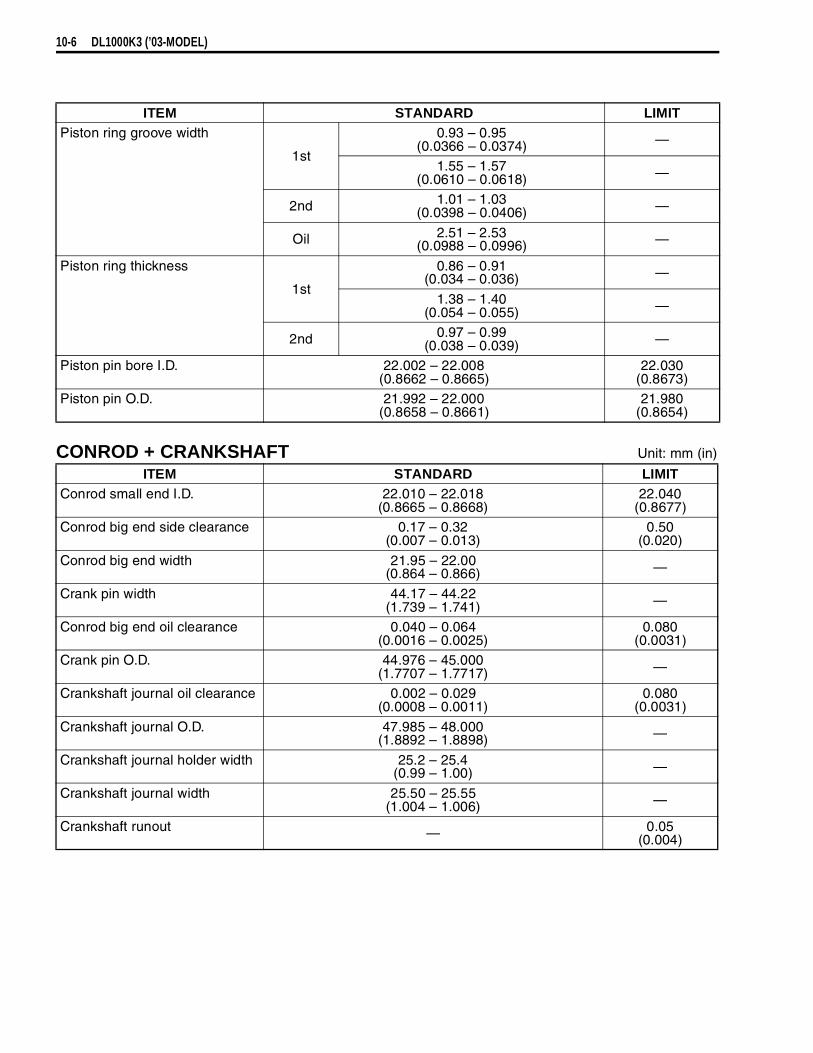
10-6 DL1000K3 (’03-MODEL)
CONROD + CRANKSHAFT Unit: mm (in)
ITEM STANDARD LIMITPiston ring groove width
1st
0.93 – 0.95(0.0366 – 0.0374) —
1.55 – 1.57(0.0610 – 0.0618) —
2nd 1.01 – 1.03(0.0398 – 0.0406) —
Oil 2.51 – 2.53(0.0988 – 0.0996) —
Piston ring thickness
1st
0.86 – 0.91(0.034 – 0.036) —
1.38 – 1.40(0.054 – 0.055) —
2nd 0.97 – 0.99(0.038 – 0.039) —
Piston pin bore I.D. 22.002 – 22.008(0.8662 – 0.8665)
22.030(0.8673)
Piston pin O.D. 21.992 – 22.000(0.8658 – 0.8661)
21.980(0.8654)
ITEM STANDARD LIMITConrod small end I.D. 22.010 – 22.018
(0.8665 – 0.8668)22.040
(0.8677)Conrod big end side clearance 0.17 – 0.32
(0.007 – 0.013)0.50
(0.020)
Conrod big end width 21.95 – 22.00(0.864 – 0.866) —
Crank pin width 44.17 – 44.22(1.739 – 1.741) —
Conrod big end oil clearance 0.040 – 0.064(0.0016 – 0.0025)
0.080(0.0031)
Crank pin O.D. 44.976 – 45.000(1.7707 – 1.7717) —
Crankshaft journal oil clearance 0.002 – 0.029(0.0008 – 0.0011)
0.080(0.0031)
Crankshaft journal O.D. 47.985 – 48.000(1.8892 – 1.8898) —
Crankshaft journal holder width 25.2 – 25.4(0.99 – 1.00) —
Crankshaft journal width 25.50 – 25.55(1.004 – 1.006) —
Crankshaft runout — 0.05(0.004)
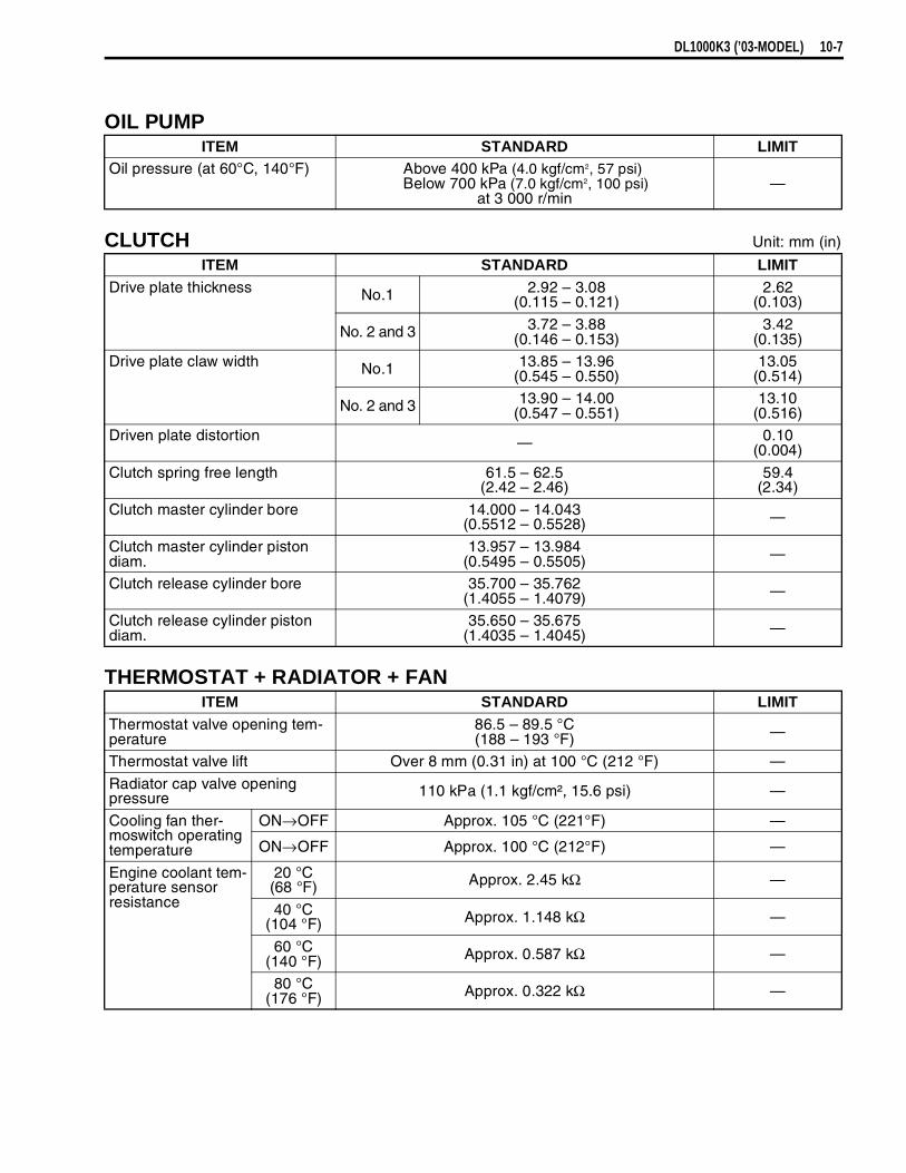
DL1000K3 (’03-MODEL) 10-7
OIL PUMP
CLUTCH Unit: mm (in)
THERMOSTAT + RADIATOR + FAN
ITEM STANDARD LIMITOil pressure (at 60°C, 140°F) Above 400 kPa (4.0 kgf/cm2, 57 psi)
Below 700 kPa (7.0 kgf/cm2, 100 psi)at 3 000 r/min
—
ITEM STANDARD LIMITDrive plate thickness No.1 2.92 – 3.08
(0.115 – 0.121)2.62
(0.103)
No. 2 and 3 3.72 – 3.88(0.146 – 0.153)
3.42(0.135)
Drive plate claw width No.1 13.85 – 13.96(0.545 – 0.550)
13.05(0.514)
No. 2 and 3 13.90 – 14.00(0.547 – 0.551)
13.10(0.516)
Driven plate distortion — 0.10(0.004)
Clutch spring free length 61.5 – 62.5(2.42 – 2.46)
59.4(2.34)
Clutch master cylinder bore 14.000 – 14.043(0.5512 – 0.5528) —
Clutch master cylinder piston diam.
13.957 – 13.984(0.5495 – 0.5505) —
Clutch release cylinder bore 35.700 – 35.762(1.4055 – 1.4079) —
Clutch release cylinder piston diam.
35.650 – 35.675(1.4035 – 1.4045) —
ITEM STANDARD LIMITThermostat valve opening tem-perature
86.5 – 89.5 °C(188 – 193 °F) —
Thermostat valve lift Over 8 mm (0.31 in) at 100 °C (212 °F) —
Radiator cap valve opening pressure 110 kPa (1.1 kgf/cm², 15.6 psi) —
Cooling fan ther-moswitch operating temperature
ON→OFF Approx. 105 °C (221°F) —
ON→OFF Approx. 100 °C (212°F) —
Engine coolant tem-perature sensor resistance
20 °C(68 °F) Approx. 2.45 kΩ —
40 °C(104 °F) Approx. 1.148 kΩ —
60 °C(140 °F) Approx. 0.587 kΩ —
80 °C(176 °F) Approx. 0.322 kΩ —
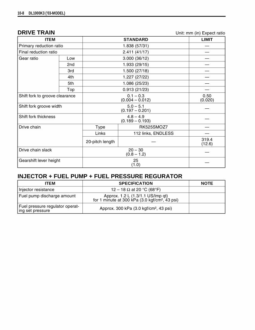
10-8 DL1000K3 (’03-MODEL)
DRIVE TRAIN Unit: mm (in) Expect ratio
INJECTOR + FUEL PUMP + FUEL PRESSURE REGURATOR
ITEM STANDARD LIMITPrimary reduction ratio 1.838 (57/31) —Final reduction ratio 2.411 (41/17) —
Gear ratio Low 3.000 (36/12) —2nd 1.933 (29/15) —
3rd 1.500 (27/18) —4th 1.227 (27/22) —
5th 1.086 (25/23) —Top 0.913 (21/23) —
Shift fork to groove clearance 0.1 – 0.3(0.004 – 0.012)
0.50(0.020)
Shift fork groove width 5.0 – 5.1(0.197 – 0.201) —
Shift fork thickness 4.8 – 4.9(0.189 – 0.193) —
Drive chain Type RK525SMOZ7 —
Links 112 links, ENDLESS —
20-pitch length — 319.4(12.6)
Drive chain slack 20 – 30(0.8 – 1.2) —
Gearshift lever height 25(1.0) —
ITEM SPECIFICATION NOTEInjector resistance 12 – 18 Ω at 20 °C (68°F)
Fuel pump discharge amount Approx. 1.2 L (1.3/1.1 US/lmp qt) for 1 minute at 300 kPa (3.0 kgf/cm², 43 psi)
Fuel pressure regulator operat-ing set pressure Approx. 300 kPa (3.0 kgf/cm², 43 psi)

DL1000K3 (’03-MODEL) 10-9
FI-SENSORS
THROTTLE BODY
ITEM SPECIFICATION NOTECMP sensor output voltage More than 3.7 VCKP sensor resistance 130 – 240 ΩCKP sensor peak voltage More than 3.7 V (When cranking)IAP sensor input voltage 4.5 – 5.5 V
IAP sensor output voltage Approx. 2.5 V at idle speedTP sensor input voltage 4.5 – 5.5 V
TP sensor resistance Closed Approx. 1.1 kΩOpened Approx. 4.3 kΩ
TP sensor output voltage Closed Approx. 1.1 VOpened Approx. 4.3 V
ECT sensor input voltage 4.5 – 5.5 VECT sensor reisitance Approx. 2.45 kΩ at 20 °C (68°F)
IAT sensor input volatage 4.5 – 5.5 VIAT sensor resistance Approx 2.45 kΩ at 20 °C (68°F)
AP sensor input voltage 4.5 – 5.5 VAP sensor output voltage Approx. 4.0 V at 760 mmHg (100 kPa)
TO sensor resistance 19.1 – 19.7 kΩTO sensor voltage Approx. 0.4 – 1.4 V
GP switch voltage More than 1.0 V (From 1st to top)Injector voltage Battery voltage
Ignition coil primary peak volt-age
More than 150 V (When cranking)
STP sensor input voltage 4.5 – 5.5 V
STP sensor resistance Closed Approx. 1.1 kΩOpened Approx. 4.3 kΩ
STP sensor output voltage Closed Approx. 1.1 VOpened Approx. 4.3 V
STV actuator resistance 4.8 – 7.2 ΩHeated oxygen sensor output voltage
less than 0.4 V at idle speed(After warming up)
European marketsHeated oxygen sensor resis-
tance4 – 5 Ω at 23 °C (73.4 °F)
PAIR solenoid valve resistance 20 – 24 Ω at 20 °C (68 °F)
ITEM SPECIFICATIONID No. 06G0 (For E-02, 19), 06G1 (For E-33), 06G2 (For E-03, 24, 28)
Bore size 45 mmFast idle r/min 1 500 – 2 100 r/min at 25 °C (77 °F)
Idle r/min 1 200 ± 100 r/min/Warmed engineThrottle cable play 2.0 – 4.0 r/min
(0.08 – 0.16 in)
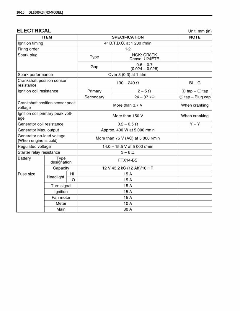
10-10 DL1000K3 (’03-MODEL)
ELECTRICAL Unit: mm (in)
ITEM SPECIFICATION NOTEIgnition timing 4° B.T.D.C. at 1 200 r/minFiring order 1·2
Spark plug Type NGK: CR8EKDenso: U24ETR
Gap 0.6 – 0.7(0.024 – 0.028)
Spark performance Over 8 (0.3) at 1 atm.
Crankshaft position sensor resistance
130 – 240 Ω Bl – G
Ignition coil resistance Primary 2 – 5 Ω
tap –
tap
Secondary 24 – 37 kΩ
tap – Plug capCrankshaft position sensor peak voltage
More than 3.7 V When cranking
Ignition coil primary peak volt-age
More than 150 V When cranking
Generator coil resistance 0.2 – 0.5 Ω Y – Y
Generator Max. output Approx. 400 W at 5 000 r/minGenerator no-load voltage(When engine is cold)
More than 75 V (AC) at 5 000 r/min
Regulated voltage 14.0 – 15.5 V at 5 000 r/minStarter relay resistance 3 – 6 ΩBattery Type
designation FTX14-BS
Capacity 12 V 43.2 kC (12 Ah)/10 HRFuse size
HeadlightHI 15 A
LO 15 ATurn signal 15 A
Ignition 15 AFan motor 15 A
Meter 10 AMain 30 A

DL1000K3 (’03-MODEL) 10-11
WATTAGE Unit: W
BRAKE + WHEEL Unit: mm (in)
ITEMSPECIFICATION
E-03, 24, 28, 33 The othersHeadlight HI 60 × 2 ←
LO 55 × 2 ←Position light 5 × 2
Brake light/Taillight 21/5 × 2 ←Turn signal light 10 × 4 ←Speedometer/Tachometer light LED ←Turn signal indicator light LED ←High beam indicator light LED ←Neutral indicator light LED ←Over drive indicator light LED ←Coolant temperature warning light
LED ←
Oil pressure warning light LED ←Fuel injection warning light LED ←License light 5 ←
ITEM STANDARD LIMITRear brake pedal height 20 – 30
(0.8 – 1.2) —
Brake disc thickness Front 5.0 ± 0.2(0.197 ± 0.008)
4.5(0.18)
Rear 5.0 ± 0.2(0.197 ± 0.008)
4.5(0.18)
Brake disc runout(Front & Rear)
— 0.30(0.012)
Master cylinder bore Front 15.870 – 15.913(0.6248 – 0.6265) —
Rear 14.000 – 14.043(0.5512 – 0.5529) —
Master cylinder piston diam. Front 15.827 – 15.854(0.6231 – 0.6242) —
Rear 13.957 – 13.984(0.5495 – 0.5506) —
Brake caliper cylinder bore Front 30.230 – 30.306(1.1902 – 1.1931) —
Rear 38.180 – 38.230(1.5031 – 1.5051) —
Brake caliper piston diam. Front 30.150 – 30.200(1.1870 – 1.1890) —
Rear 38.098 – 38.148(1.4999 – 1.5019) —
Wheel rim runout(Front & Rear)
Axial — 2.0(0.08)
Radial — 2.0(0.08)
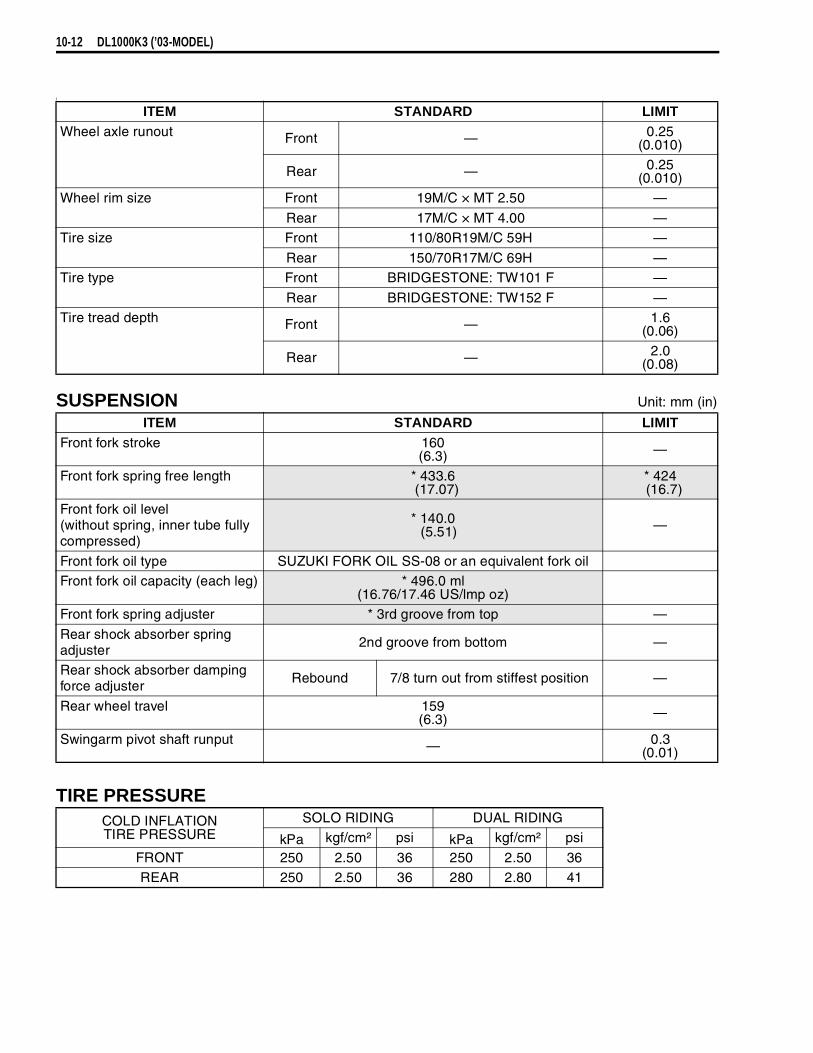
10-12 DL1000K3 (’03-MODEL)
)
SUSPENSION Unit: mm (in)
TIRE PRESSURE
ITEM STANDARD LIMITWheel axle runout Front — 0.25
(0.010)
Rear — 0.25(0.010)
Wheel rim size Front 19M/C × MT 2.50 —
Rear 17M/C × MT 4.00 —Tire size Front 110/80R19M/C 59H —
Rear 150/70R17M/C 69H —Tire type Front BRIDGESTONE: TW101 F —
Rear BRIDGESTONE: TW152 F —Tire tread depth Front — 1.6
(0.06)
Rear — 2.0(0.08)
ITEM STANDARD LIMITFront fork stroke 160
(6.3) —
Front fork spring free length * 433.6 (17.07)
* 424 (16.7)
Front fork oil level(without spring, inner tube fully compressed)
* 140.0 (5.51) —
Front fork oil type SUZUKI FORK OIL SS-08 or an equivalent fork oilFront fork oil capacity (each leg) * 496.0 ml
(16.76/17.46 US/lmp oz)Front fork spring adjuster * 3rd groove from top —
Rear shock absorber spring adjuster
2nd groove from bottom —
Rear shock absorber damping force adjuster
Rebound 7/8 turn out from stiffest position —
Rear wheel travel 159(6.3) —
Swingarm pivot shaft runput — 0.3(0.01)
COLD INFLATIONTIRE PRESSURE
SOLO RIDING DUAL RIDING
kPa kgf/cm² psi kPa kgf/cm² psi
FRONT 250 2.50 36 250 2.50 36REAR 250 2.50 36 280 2.80 41
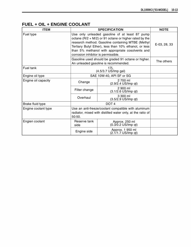
DL1000K3 (’03-MODEL) 10-13
FUEL + OIL + ENGINE COOLANTITEM SPECIFICATION NOTE
Fuel type Use only unleaded gasoline of at least 87 pumpoctane (R/2 + M/2) or 91 octane or higher rated by theresearch method. Gasoline containing MTBE (MethylTertiary Butyl Ether), less than 10% ethanol, or lessthan 5% methanol with appropriate cosolvents andcorrosion inhibitor is permissible.
E-03, 28, 33
Gasoline used should be graded 91 octane or higher.An unleaded gasoline is recommended.
The others
Fuel tank 17L(4.5/3.7 US/lmp gal)
Engine oil type SAE 10W-40, API SF or SGEngine oil capacity Change 2 700 ml
(2.9/2.4 US/lmp qt)
Filter change 2 900 ml(3.1/2.6 US/lmp qt)
Overhaul 3 300 ml(3.5/2.9 US/lmp qt)
Brake fluid type DOT 4Engine coolant type Use an anti-freeze/coolant compatible with aluminum
radiator, mixed with distilled water only, at the ratio of50:50.
Engien coolant Reserve tank side
Approx. 250 ml(0.3/0.2 US/lmp qt)
Engine side Approx. 1 950 ml(2.1/1.7 US/lmp qt)

10-14 DL1000K3 (’03-MODEL)
FRONT FORKCONSTRUCTION
Spring adjusterO-ringO-ringSpring seatSpacerWasherSpringInner rod/damper rod (cartridge)Inner tubeDust sealOil seal stopper ringOil sealOil seal retainerGuide metalSlide metalOil lock pieceOuter tube
Front fork cap boltInner rod lock nutFront axle pinch boltDamper rod bolt
ITEM N·m kgf-m lb-ft
23 2.3 16.5
20 2.0 14.5
23 2.3 16.5
20 2.0 14.5
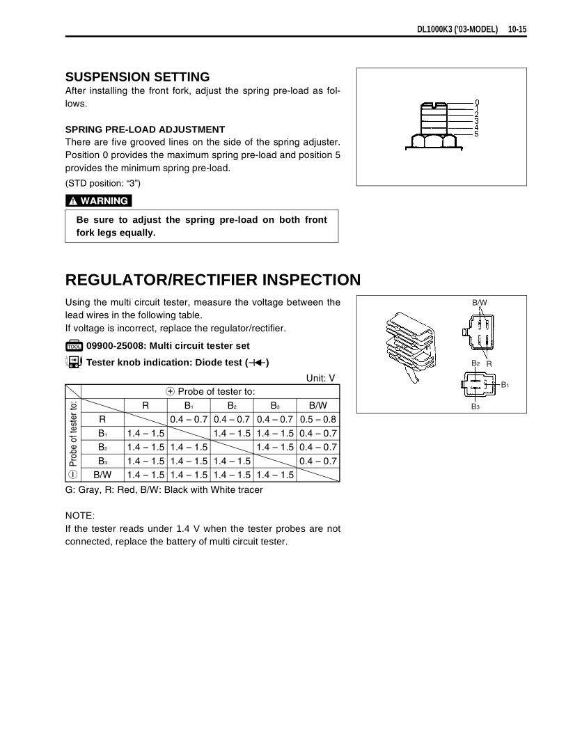
DL1000K3 (’03-MODEL) 10-15
SUSPENSION SETTINGAfter installing the front fork, adjust the spring pre-load as fol-lows.
SPRING PRE-LOAD ADJUSTMENTThere are five grooved lines on the side of the spring adjuster.Position 0 provides the maximum spring pre-load and position 5provides the minimum spring pre-load.
(STD position: “3”)
REGULATOR/RECTIFIER INSPECTIONUsing the multi circuit tester, measure the voltage between thelead wires in the following table.If voltage is incorrect, replace the regulator/rectifier.
09900-25008: Multi circuit tester set
Tester knob indication: Diode test ( )
G: Gray, R: Red, B/W: Black with White tracer
NOTE:If the tester reads under 1.4 V when the tester probes are notconnected, replace the battery of multi circuit tester.
Be sure to adjust the spring pre-load on both frontfork legs equally.
Unit: V
Probe of tester to:
Pro
be o
f tes
ter t
o: R B1 B2 B3 B/WR 0.4 – 0.7 0.4 – 0.7 0.4 – 0.7 0.5 – 0.8
B1 1.4 – 1.5 1.4 – 1.5 1.4 – 1.5 0.4 – 0.7B2 1.4 – 1.5 1.4 – 1.5 1.4 – 1.5 0.4 – 0.7
B3 1.4 – 1.5 1.4 – 1.5 1.4 – 1.5 0.4 – 0.7B/W 1.4 – 1.5 1.4 – 1.5 1.4 – 1.5 1.4 – 1.5
B/W
RB2
B1
B3

11
DL1000K4 (’04-MODEL) 11-1
CONTENTS
DL1000K4 (’04-MODEL)
This chapter describes service specifications, service data and servicing procedures which dif-fer from those of the DL1000K3 (’03-MODEL).
NOTE:* Any differences between the DL1000K3 (’03-model) and DL1000K4 (’04-model) in specifica-
tions and service data are indicated with an asterisk mark (*).* Please refer to the chapters 1 through 10 for details which are not given in this chapter.
SPECIFICATIONS .......................................................................................11- 2
SERVICE DATA ...........................................................................................11- 3SPECIAL TOOL ...........................................................................................11-12
FI SYSTEM ..................................................................................................11-15
COMBINATION METER ..............................................................................11-16WIRE HARNESS ROUTING ........................................................................11-22
COWLING SETUP .......................................................................................11-24

11-2 DL1000K4 (’04-MODEL)
SPECIFICATIONSDIMENSIONS AND DRY MASSOverall length ...................................................................................... 2 295 mm (90.4 in)Overall width .......................................................................................* 910 mm (35.8 in)Overall height ......................................................................................* 1 395 mm (54.9 in)Wheelbase .......................................................................................... 1 535 mm (60.4 in)Ground clearance................................................................................ 165 mm (6.5 in)Seat height .......................................................................................... 840 mm (33.1 in)Dry mass.............................................................................................* 208 kg (458 lbs)
* 210 kg (462 lbs) .............. E-33
ENGINEType..................................................................................................... 4-stroke, Liquid-cooled, DOHC, 90° degree V-twinNumber of cylinders ............................................................................ 2Bore .................................................................................................... 98.0 mm (3.858 in)Stroke.................................................................................................. 66.0 mm (2.598 in)Displacement ...................................................................................... 996 cm3 (60.8 cu. in)Compression ratio ............................................................................... 11.3 : 1Fuel system......................................................................................... Fuel injection systemAir cleaner ........................................................................................... Non-woven fabric elementStarter system..................................................................................... ElectricLubrication system .............................................................................. Wet sumpIdle speed ........................................................................................... 1 200 ± 100 r/min
DRIVE TRAINClutch .................................................................................................. Wet multi-plate typeTransmission ....................................................................................... 6-speed constant meshGearshift pattern ................................................................................ 1-down, 5-upPrimary reduction ratio........................................................................ 1.838 (57/31)Gear ratios, Low................................................................................ 3.000 (36/12)
2nd ................................................................................ 1.933 (29/15)3rd ................................................................................. 1.500 (27/18)4th ................................................................................. 1.227 (27/22)5th ................................................................................. 1.086 (25/23)Top................................................................................. 0.913 (21/23)
Final reduction ratio............................................................................. 2.411 (41/17)Drive chain .......................................................................................... RK525 SMOZ7, 112 links
CHASSISFront suspension................................................................................. Telescopic, coil spring, oil damped Rear suspension ................................................................................. Link type, coil spring, oil dampedFront suspension stroke ...................................................................... 160 mm (6.3 in)Rear wheel travel ................................................................................ 159 mm (6.3 in)Caster ................................................................................................. 26° 30’Trail...................................................................................................... 111 mm (4.4 in)Steering angle ..................................................................................... 40° (right & left)Turning radius ..................................................................................... 2.7 m (8.86 ft)Front brake .......................................................................................... Disk brake, twinRear brake .......................................................................................... Disk brakeFront tire size ...................................................................................... 110/80 R19M/C 59H, tubelessRear tire size ....................................................................................... 150/70 R17M/C 69H, tubeless
ELECTRICALIgnition type......................................................................................... Electronic ignition (Transistorized)Ignition timing ...................................................................................... 4° B.T.D.C. at 1 200 r/minSpark plug ........................................................................................... NGK CR8EK or DENSO U24ETRBattery................................................................................................. 12V 43.2 kC (12Ah)/10 HRGenerator ............................................................................................ Three-phase A.C. generatorMain fuse ............................................................................................ 30 AFuse ....................................................................................................* 10/10/15/15/15/15 AHeadlight ............................................................................................. 12 V 60/55 W × 2 (H4 × 2)Position/Parking light........................................................................... 12 V 5 W × 2........................Except E-03, 24, 28, 33Brake light/Taillight .............................................................................. 12 V 21/5 W × 2License plate light ............................................................................... 12 V 5 WTurn signal /Hazard light .....................................................................* 12 V 21 WSpeedometer light ............................................................................... LEDTachometer light.................................................................................. LEDTurn signal indicator light .................................................................... LEDNeutral indicator light .......................................................................... LEDHigh beam indicator light .................................................................... LEDFuel injection warning light.................................................................. LED(Coolant temperature, Oil pressure)
CAPACITIESFuel tank ............................................................................................. 22 L (5.81/4.84 US/Imp gal)Engine oil, oil change......................................................................... 2 700 ml (2.9/2.4 US/Imp qt)
with filter change.............................................................. 2 900 ml (3.1/2.6 US/Imp qt)overhaul ........................................................................... 3 300 ml (3.5/2.9 US/Imp qt)
Coolant................................................................................................ 2.2 L (2.3/1.9 US/Imp qt)

DL1000K4 (’04-MODEL) 11-3
SERVICE DATAVALVE + GUIDE Unit: mm (in)
ITEM STANDARD LIMITValve diam. IN. 36
(1.42) —
EX. 33(1.30) —
Tappet clearance (when cold) IN. 0.10 – 0.20(0.004 – 0.008) —
EX. 0.20 – 0.30(0.008 – 0.012) —
Valve guide to valve stem clear-ance IN. 0.010 – 0.037
(0.0004 – 0.0015) —
EX. 0.030 – 0.057(0.0012 – 0.0022) —
Valve guide I.D. IN. & EX. 5.500 – 5.512(0.2165 – 0.2170) —
Valve stem O.D. IN. 5.475 – 5.490(0.2156 – 0.2161) —
EX. 5.455 – 5.470(0.2148 – 0.2154) —
Valve stem deflection IN. & EX. — 0.35(0.014)
Valve stem runout IN. & EX. — 0.05(0.002)
Valve head thickness IN. & EX. — 0.5(0.02)
Valve seat width IN. & EX. 0.9 – 1.1(0.035 – 0.043) —
Valve head radial runout IN. & EX. — 0.03(0.001)
Valve spring free length IN. & EX. — 39.6(1.56)
Valve spring tensionIN. & EX.
197 – 227 N(20.1 – 23.1 kgf, 44.3 – 51.0 lbs)
at length 35.6 mm (1.40 in)—

11-4 DL1000K4 (’04-MODEL)
CAMSHAFT + CYLINDER HEAD Unit: mm (in)
CYLINDER + PISTON + PISTON RING Unit: mm (in)
ITEM STANDARD LIMITCam height IN. 36.28 – 36.32
(1.428 – 1.430)35.98
(1.417)
EX. 35.68 – 35.72(1.405 – 1.406)
35.38(1.393)
Camshaft journal oil clearance IN. & EX. 0.019 – 0.053(0.0007 – 0.0021)
0.150(0.0059)
Camshaft journal holder I.D. IN. & EX. 22.012 – 22.025(0.8666 – 0.8671) —
Camshaft journal O.D. IN. & EX. 21.972 – 21.993(0.8650 – 0.8659) —
Camshaft runout IN. & EX. — 0.10(0.004)
Cam drive idle gear/sprocket thrust clearance
0.15 – 0.29(0.006 – 0.011) —
Cylinder head distortion — 0.05(0.002)
ITEM STANDARD LIMITCompression pressure(Automatic de-comp. actuated) 1 000 – 1 400 kPa
(10 – 14 kgf/cm², 142 – 199 psi)800 kPa
(8 kgf/cm²,114 psi)
Compression pressure differ-ence — 200 kPa
(2 kgf/cm², 28 psi)
Piston to cylinder clearance 0.015 – 0.025(0.0006 – 0.0010)
0.12(0.0047)
Cylinder bore 98.000 – 98.015(3.8583 – 3.8589)
Nicks or Scratches
Piston diam. 97.980 – 97.995(3.8575 – 3.8581)
Measure at 10 mm (0.4 in) from the skirt end.97.880
(3.8535)
Cylinder distortion — 0.05(0.002)
Piston ring free end gap 1st Approx. 8.8 (0.35) 7.0(0.28)
2nd Approx. 10.1 (0.40) 8.1(0.32)
Piston ring end gap 1st 0.15 – 0.35(0.006 – 0.014)
0.5(0.02)
2nd RN 0.30 – 0.45(0.012 – 0.018)
0.7(0.03)
Piston ring to groove clearance 1st — 0.18(0.0071)
2nd — 0.15(0.0059)
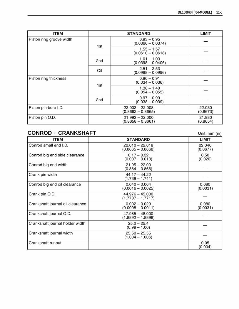
DL1000K4 (’04-MODEL) 11-5
CONROD + CRANKSHAFT Unit: mm (in)
ITEM STANDARD LIMITPiston ring groove width
1st
0.93 – 0.95(0.0366 – 0.0374) —
1.55 – 1.57(0.0610 – 0.0618) —
2nd 1.01 – 1.03(0.0398 – 0.0406) —
Oil 2.51 – 2.53(0.0988 – 0.0996) —
Piston ring thickness
1st
0.86 – 0.91(0.034 – 0.036) —
1.38 – 1.40(0.054 – 0.055) —
2nd 0.97 – 0.99(0.038 – 0.039) —
Piston pin bore I.D. 22.002 – 22.008(0.8662 – 0.8665)
22.030(0.8673)
Piston pin O.D. 21.992 – 22.000(0.8658 – 0.8661)
21.980(0.8654)
ITEM STANDARD LIMITConrod small end I.D. 22.010 – 22.018
(0.8665 – 0.8668)22.040
(0.8677)
Conrod big end side clearance 0.17 – 0.32(0.007 – 0.013)
0.50(0.020)
Conrod big end width 21.95 – 22.00(0.864 – 0.866) —
Crank pin width 44.17 – 44.22(1.739 – 1.741) —
Conrod big end oil clearance 0.040 – 0.064(0.0016 – 0.0025)
0.080(0.0031)
Crank pin O.D. 44.976 – 45.000(1.7707 – 1.7717) —
Crankshaft journal oil clearance 0.002 – 0.029(0.0008 – 0.0011)
0.080(0.0031)
Crankshaft journal O.D. 47.985 – 48.000(1.8892 – 1.8898) —
Crankshaft journal holder width 25.2 – 25.4(0.99 – 1.00) —
Crankshaft journal width 25.50 – 25.55(1.004 – 1.006) —
Crankshaft runout — 0.05(0.004)
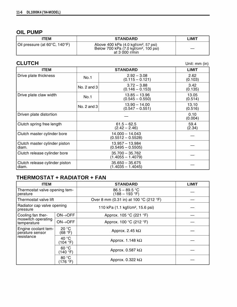
11-6 DL1000K4 (’04-MODEL)
OIL PUMP
CLUTCH Unit: mm (in)
THERMOSTAT + RADIATOR + FAN
ITEM STANDARD LIMITOil pressure (at 60°C, 140°F) Above 400 kPa (4.0 kgf/cm², 57 psi)
Below 700 kPa (7.0 kgf/cm², 100 psi)at 3 000 r/min
—
ITEM STANDARD LIMITDrive plate thickness No.1 2.92 – 3.08
(0.115 – 0.121)2.62
(0.103)
No. 2 and 3 3.72 – 3.88(0.146 – 0.153)
3.42(0.135)
Drive plate claw width No.1 13.85 – 13.96(0.545 – 0.550)
13.05(0.514)
No. 2 and 3 13.90 – 14.00(0.547 – 0.551)
13.10(0.516)
Driven plate distortion — 0.10(0.004)
Clutch spring free length 61.5 – 62.5(2.42 – 2.46)
59.4(2.34)
Clutch master cylinder bore 14.000 – 14.043(0.5512 – 0.5528) —
Clutch master cylinder piston diam.
13.957 – 13.984(0.5495 – 0.5505) —
Clutch release cylinder bore 35.700 – 35.762(1.4055 – 1.4079) —
Clutch release cylinder piston diam.
35.650 – 35.675(1.4035 – 1.4045) —
ITEM STANDARD LIMITThermostat valve opening tem-perature
86.5 – 89.5 °C(188 – 193 °F) —
Thermostat valve lift Over 8 mm (0.31 in) at 100 °C (212 °F) —
Radiator cap valve opening pressure 110 kPa (1.1 kgf/cm², 15.6 psi) —
Cooling fan ther-moswitch operating temperature
ON→OFF Approx. 105 °C (221 °F) —
ON→OFF Approx. 100 °C (212 °F) —
Engine coolant tem-perature sensor resistance
20 °C(68 °F) Approx. 2.45 kΩ —
40 °C(104 °F) Approx. 1.148 kΩ —
60 °C(140 °F) Approx. 0.587 kΩ —
80 °C(176 °F) Approx. 0.322 kΩ —

DL1000K4 (’04-MODEL) 11-7
DRIVE TRAIN Unit: mm (in) Expect ratio
INJECTOR + FUEL PUMP + FUEL PRESSURE REGURATOR
ITEM STANDARD LIMITPrimary reduction ratio 1.838 (57/31) —Final reduction ratio 2.411 (41/17) —
Gear ratio Low 3.000 (36/12) —2nd 1.933 (29/15) —
3rd 1.500 (27/18) —4th 1.227 (27/22) —
5th 1.086 (25/23) —Top 0.913 (21/23) —
Shift fork to groove clearance 0.1 – 0.3(0.004 – 0.012)
0.50(0.020)
Shift fork groove width 5.0 – 5.1(0.197 – 0.201) —
Shift fork thickness 4.8 – 4.9(0.189 – 0.193) —
Drive chain Type RK525SMOZ7 —
Links 112 links, ENDLESS —
20-pitch length — 319.4(12.6)
Drive chain slack 20 – 30(0.8 – 1.2) —
Gearshift lever height 25(1.0) —
ITEM SPECIFICATION NOTEInjector resistance 12 – 18 Ω at 20 °C (68 °F)Fuel pump discharge amount Approx. 1.2 L (1.3/1.1 US/lmp qt)
for 1 minute at 300 kPa (3.0 kgf/cm², 43 psi)Fuel pressure regulator operat-ing set pressure Approx. 300 kPa (3.0 kgf/cm², 43 psi)

11-8 DL1000K4 (’04-MODEL)
FI-SENSORS
THROTTLE BODY
ITEM SPECIFICATION NOTECMP sensor output voltage More than 3.7 VCKP sensor resistance 130 – 240 ΩCKP sensor peak voltage More than 3.7 V (When cranking)IAP sensor input voltage 4.5 – 5.5 V
IAP sensor output voltage Approx. 2.5 V at idle speedTP sensor input voltage 4.5 – 5.5 V
TP sensor resistance Closed Approx. 1.1 kΩOpened Approx. 4.3 kΩ
TP sensor output voltage Closed Approx. 1.1 VOpened Approx. 4.3 V
ECT sensor input voltage 4.5 – 5.5 VECT sensor reisitance Approx. 2.45 kΩ at 20 °C (68 °F)
IAT sensor input volatage 4.5 – 5.5 VIAT sensor resistance Approx 2.45 kΩ at 20 °C (68 °F)
AP sensor input voltage 4.5 – 5.5 VAP sensor output voltage Approx. 4.0 V at 760 mmHg (100 kPa)
TO sensor resistance 19.1 – 19.7 kΩTO sensor voltage Approx. 0.4 – 1.4 V
GP switch voltage More than 1.0 V (From 1st to top)Injector voltage Battery voltage
Ignition coil primary peak volt-age More than 150 V (When cranking)
STP sensor input voltage 4.5 – 5.5 VSTP sensor resistance Closed Approx. 1.1 kΩ
Opened Approx. 4.3 kΩSTP sensor output voltage Closed Approx. 1.1 V
Opened Approx. 4.3 VSTV actuator resistance 4.8 – 7.2 ΩHeated oxygen sensor output voltage
Less than 0.4 V at idle speed(After warming up)
European marketsHeated oxygen sensor resis-
tance 4 – 5 Ω at 23 °C (73.4 °F)
PAIR solenoid valve resistance 20 – 24 Ω at 20 °C (68 °F)
ITEM SPECIFICATIONID No. * 06G3 (For E-02, 19), 06G4 (For E-33), 06G5 (For E-03, 24, 28)
Bore size 45 mmFast idle r/min 1 500 – 2 100 r/min at 25 °C (77 °F)
Idle r/min 1 200 ± 100 r/min/Warmed engineThrottle cable play 2.0 – 4.0 r/min
(0.08 – 0.16 in)
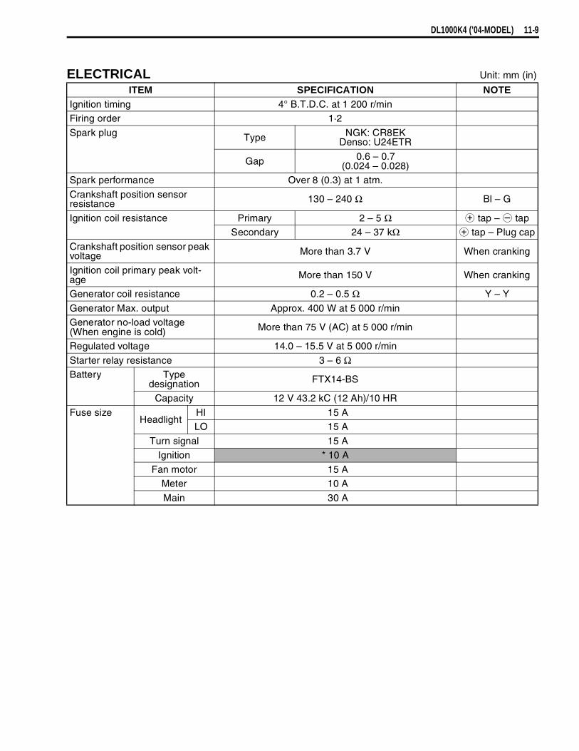
DL1000K4 (’04-MODEL) 11-9
ELECTRICAL Unit: mm (in)
ITEM SPECIFICATION NOTEIgnition timing 4° B.T.D.C. at 1 200 r/minFiring order 1·2
Spark plug Type NGK: CR8EKDenso: U24ETR
Gap 0.6 – 0.7(0.024 – 0.028)
Spark performance Over 8 (0.3) at 1 atm.
Crankshaft position sensor resistance 130 – 240 Ω Bl – G
Ignition coil resistance Primary 2 – 5 Ω
tap –
tapSecondary 24 – 37 kΩ
tap – Plug cap
Crankshaft position sensor peak voltage More than 3.7 V When cranking
Ignition coil primary peak volt-age More than 150 V When cranking
Generator coil resistance 0.2 – 0.5 Ω Y – Y
Generator Max. output Approx. 400 W at 5 000 r/minGenerator no-load voltage(When engine is cold) More than 75 V (AC) at 5 000 r/min
Regulated voltage 14.0 – 15.5 V at 5 000 r/min
Starter relay resistance 3 – 6 ΩBattery Type
designation FTX14-BS
Capacity 12 V 43.2 kC (12 Ah)/10 HR
Fuse sizeHeadlight
HI 15 ALO 15 A
Turn signal 15 AIgnition * 10 A
Fan motor 15 AMeter 10 A
Main 30 A
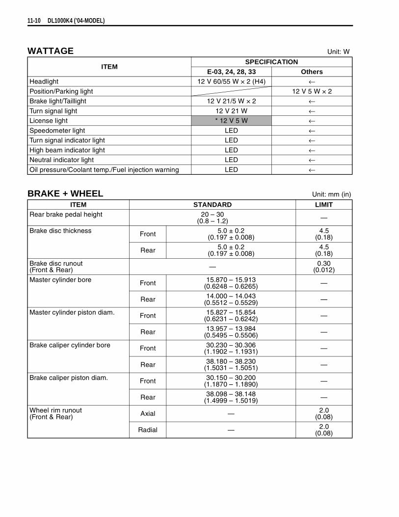
11-10 DL1000K4 (’04-MODEL)
WATTAGE Unit: W
BRAKE + WHEEL Unit: mm (in)
ITEMSPECIFICATION
E-03, 24, 28, 33 OthersHeadlight 12 V 60/55 W × 2 (H4) ←Position/Parking light 12 V 5 W × 2Brake light/Taillight 12 V 21/5 W × 2 ←Turn signal light 12 V 21 W ←License light * 12 V 5 W ←Speedometer light LED ←Turn signal indicator light LED ←High beam indicator light LED ←Neutral indicator light LED ←Oil pressure/Coolant temp./Fuel injection warning LED ←
ITEM STANDARD LIMITRear brake pedal height 20 – 30
(0.8 – 1.2) —
Brake disc thickness Front 5.0 ± 0.2(0.197 ± 0.008)
4.5(0.18)
Rear 5.0 ± 0.2(0.197 ± 0.008)
4.5(0.18)
Brake disc runout(Front & Rear) — 0.30
(0.012)
Master cylinder bore Front 15.870 – 15.913(0.6248 – 0.6265) —
Rear 14.000 – 14.043(0.5512 – 0.5529) —
Master cylinder piston diam. Front 15.827 – 15.854(0.6231 – 0.6242) —
Rear 13.957 – 13.984(0.5495 – 0.5506) —
Brake caliper cylinder bore Front 30.230 – 30.306(1.1902 – 1.1931) —
Rear 38.180 – 38.230(1.5031 – 1.5051) —
Brake caliper piston diam. Front 30.150 – 30.200(1.1870 – 1.1890) —
Rear 38.098 – 38.148(1.4999 – 1.5019) —
Wheel rim runout(Front & Rear) Axial — 2.0
(0.08)
Radial — 2.0(0.08)

DL1000K4 (’04-MODEL) 11-11
SUSPENSION Unit: mm (in)
TIRE PRESSURE
ITEM STANDARD LIMITWheel axle runout Front — 0.25
(0.010)
Rear — 0.25(0.010)
Wheel rim size Front 19M/C × MT 2.50 —
Rear 17M/C × MT 4.00 —Tire size Front 110/80R19M/C 59H —
Rear 150/70R17M/C 69H —Tire type Front BRIDGESTONE: TW101 F —
Rear BRIDGESTONE: TW152 F —Tire tread depth Front — 1.6
(0.06)
Rear — 2.0(0.08)
ITEM STANDARD LIMITFront fork stroke 160
(6.3) —
Front fork spring free length 433.6(17.07)
424(16.7)
Front fork oil level(without spring, inner tube fully compressed)
140.0(5.51) —
Front fork oil type SUZUKI FORK OIL SS-08 or an equivalent fork oil
Front fork oil capacity (each leg) 496.0 ml(16.76/17.46 US/lmp oz)
Front fork spring adjuster 3rd groove from top —Rear shock absorber spring adjuster 2nd groove from bottom —
Rear shock absorber damping force adjuster Rebound 7/8 turn out from stiffest position —
Rear wheel travel 159(6.3) —
Swingarm pivot shaft runput — 0.3(0.01)
COLD INFLATIONTIRE PRESSURE
SOLO RIDING DUAL RIDINGkPa kgf/cm² psi kPa kgf/cm² psi
FRONT 250 2.50 36 250 2.50 36REAR 250 2.50 36 280 2.80 41

11-12 DL1000K4 (’04-MODEL)
FUEL + OIL + ENGINE COOLANT
SPECIAL TOOL
ITEM SPECIFICATION NOTEFuel type Use only unleaded gasoline of at least 87 pump
octane (R/2 + M/2) or 91 octane or higher rated by theresearch method. Gasoline containing MTBE (MethylTertiary Butyl Ether), less than 10% ethanol, or lessthan 5% methanol with appropriate cosolvents andcorrosion inhibitor is permissible.
E-03, 28, 33
Gasoline used should be graded 91 octane or higher.An unleaded gasoline is recommended.
The others
Fuel tank 17 L(4.5/3.7 US/lmp gal)
Engine oil type SAE 10W-40, API SF or SGEngine oil capacity Change 2 700 ml
(2.9/2.4 US/lmp qt)
Filter change 2 900 ml(3.1/2.6 US/lmp qt)
Overhaul 3 300 ml(3.5/2.9 US/lmp qt)
Brake fluid type DOT 4Engine coolant type Use an anti-freeze/coolant compatible with aluminum
radiator, mixed with distilled water only, at the ratio of50:50.
Engien coolant Reserve tank side
Approx. 250 ml(0.3/0.2 US/lmp qt)
Engine side Approx. 1 950 ml(2.1/1.7 US/lmp qt)
09930-82720Mode select switch
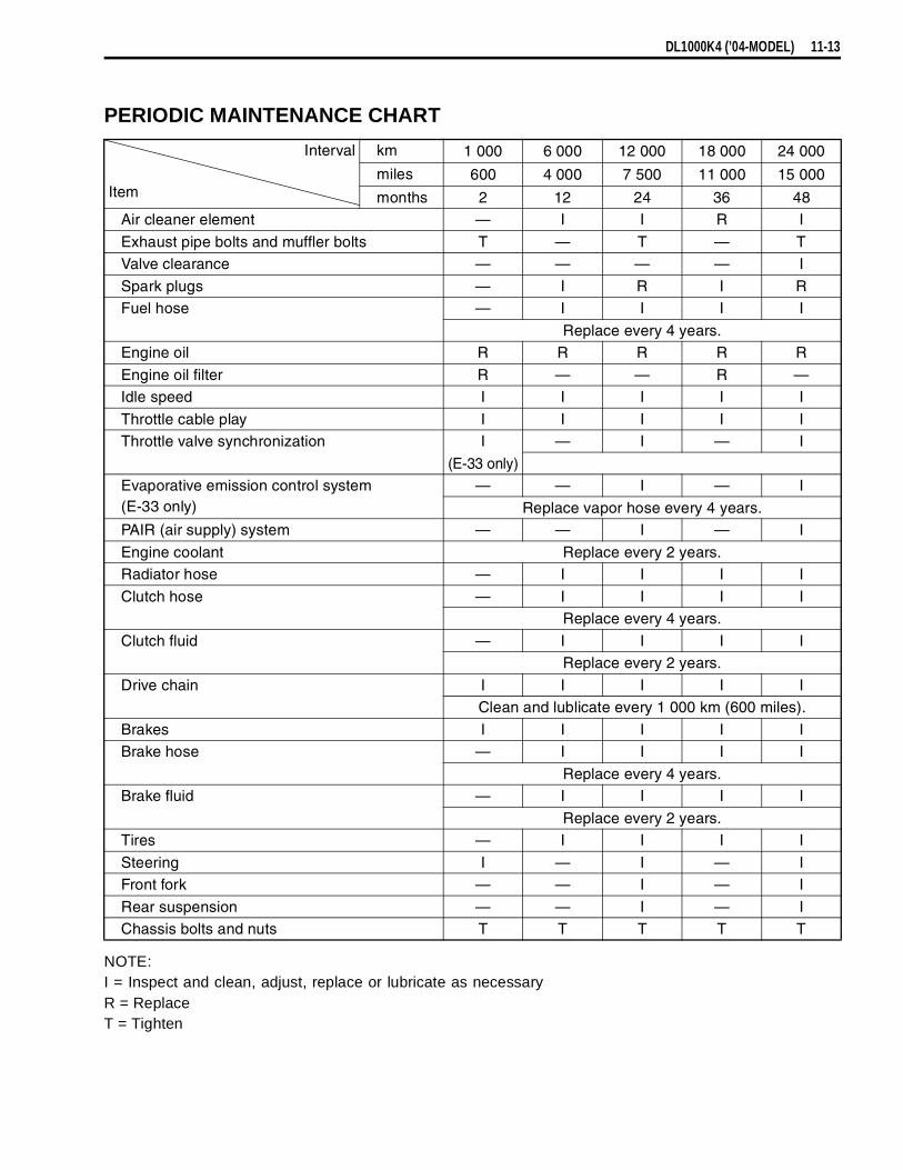
DL1000K4 (’04-MODEL) 11-13
PERIODIC MAINTENANCE CHART
NOTE:I = Inspect and clean, adjust, replace or lubricate as necessaryR = ReplaceT = Tighten
Interval
Item
km 1 000 6 000 12 000 18 000 24 000
miles 600 4 000 7 500 11 000 15 000
months 2 12 24 36 48Air cleaner element — I I R I
Exhaust pipe bolts and muffler bolts T — T — TValve clearance — — — — I
Spark plugs — I R I RFuel hose — I I I I
Replace every 4 years.Engine oil R R R R R
Engine oil filter R — — R —Idle speed I I I I I
Throttle cable play I I I I IThrottle valve synchronization I — I — I
(E-33 only)Evaporative emission control system(E-33 only)
— — I — I
Replace vapor hose every 4 years.PAIR (air supply) system — — I — I
Engine coolant Replace every 2 years.Radiator hose — I I I I
Clutch hose — I I I IReplace every 4 years.
Clutch fluid — I I I IReplace every 2 years.
Drive chain I I I I IClean and lublicate every 1 000 km (600 miles).
Brakes I I I I IBrake hose — I I I I
Replace every 4 years.Brake fluid — I I I I
Replace every 2 years.Tires — I I I I
Steering I — I — IFront fork — — I — I
Rear suspension — — I — IChassis bolts and nuts T T T T T
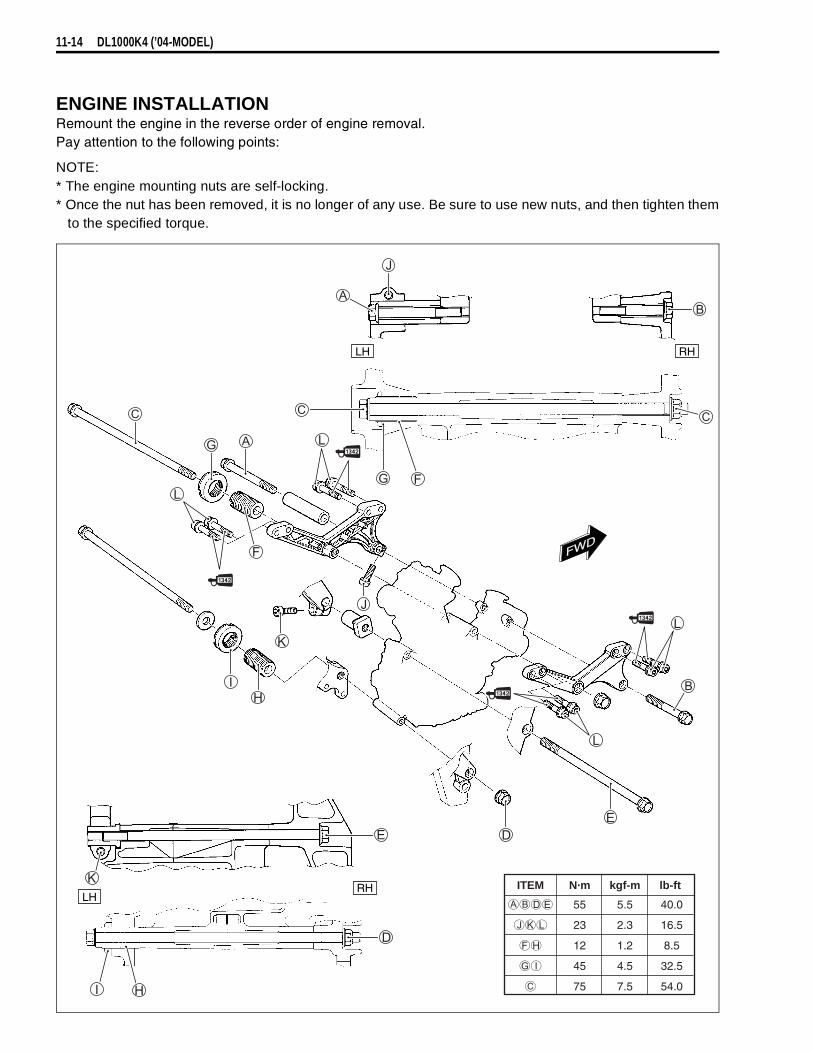
11-14 DL1000K4 (’04-MODEL)
ENGINE INSTALLATIONRemount the engine in the reverse order of engine removal.Pay attention to the following points:
NOTE:* The engine mounting nuts are self-locking.* Once the nut has been removed, it is no longer of any use. Be sure to use new nuts, and then tighten them
to the specified torque.
ITEM N·m kgf-m lb-ft
55 5.5 40.0
23 2.3 16.5
12 1.2 8.5
45 4.5 32.5
75 7.5 54.0
FWD
RHLH
RHLH

DL1000K4 (’04-MODEL) 11-15
FI SYSTEM• ECM terminals have been change is as following.• To inspect the sensors according to the FI malfunction codes,
refer to the following. (DL1000 service manual 4-32 to 4-50)
09930-82720: Mode select switch
DL1000K3 model
DL1000K4 model
Ignition coil #1
PM
GP
Ignition coil #2
PA
FP
Ground
CLT
AT
Tachometer
TPS
E2
Fuel injector #1
MO+
Ground
Fuel injector #2
STA
THW
SOL
MO–
TECH
HO2 (OXH)
—
—
—
HO2 (OX)
TS
VCC
Ground
NT
—
N+
DON
G+
—
—
Ground
VM
—
THA
—
STPS
+B
N–
Clamp
HO2 sensor
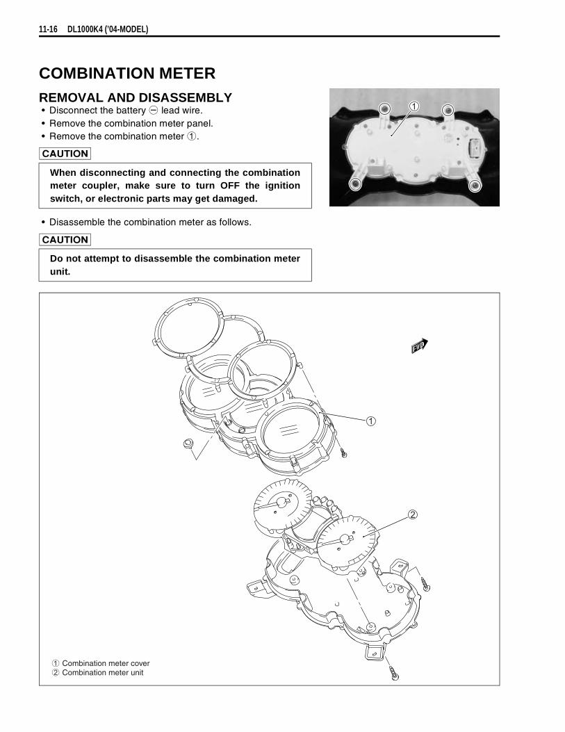
11-16 DL1000K4 (’04-MODEL)
COMBINATION METERREMOVAL AND DISASSEMBLY• Disconnect the battery
lead wire.• Remove the combination meter panel.• Remove the combination meter
.
• Disassemble the combination meter as follows.
When disconnecting and connecting the combinationmeter coupler, make sure to turn OFF the ignitionswitch, or electronic parts may get damaged.
Do not attempt to disassemble the combination meterunit.
Combination meter cover Combination meter unit

DL1000K4 (’04-MODEL) 11-17
INSPECTIONLED (LIGHT EMITTING DIODE)Check that the LED lights immediately after turning the ignition switch on.If the LED fails in operation, replace the combination meter unit with a new one after checking its wire har-ness/coupler.
STEPPING MOTORCheck that the pointer calibrates itself immediately after turning the ignition switch on and stops at startingpoint.If abnormal condition is found, replace the combination meter unit with a new one after checking its wire har-ness/coupler.
NOTE:The pointer may not return to the proper position even turning the ignition switch on under low temperaturecondition. In that case, you can reset the pointer to the proper position by following the instruction below:
1) With the ADJ switch
pressed, turn the ignition switch on.2) Keep pushing the ADJ switch
for 3 to 5 seconds.3) Push the ADJ switch
twice (within 1 second). → Reset* Complete the operation within 10 seconds after the ignition switch has been turned on.
Pointer will return to the starting point right after the completion of the operation. In the case of the pointernot returning to the proper position after doing above, replace the combination meter unit.
ADJ SWITCH
Time Ignition switch ADJ switch
OFF
ON0
••
3 sec
5 sec•
••••
10 sec
PUSH
Release
Push
Push → Reset
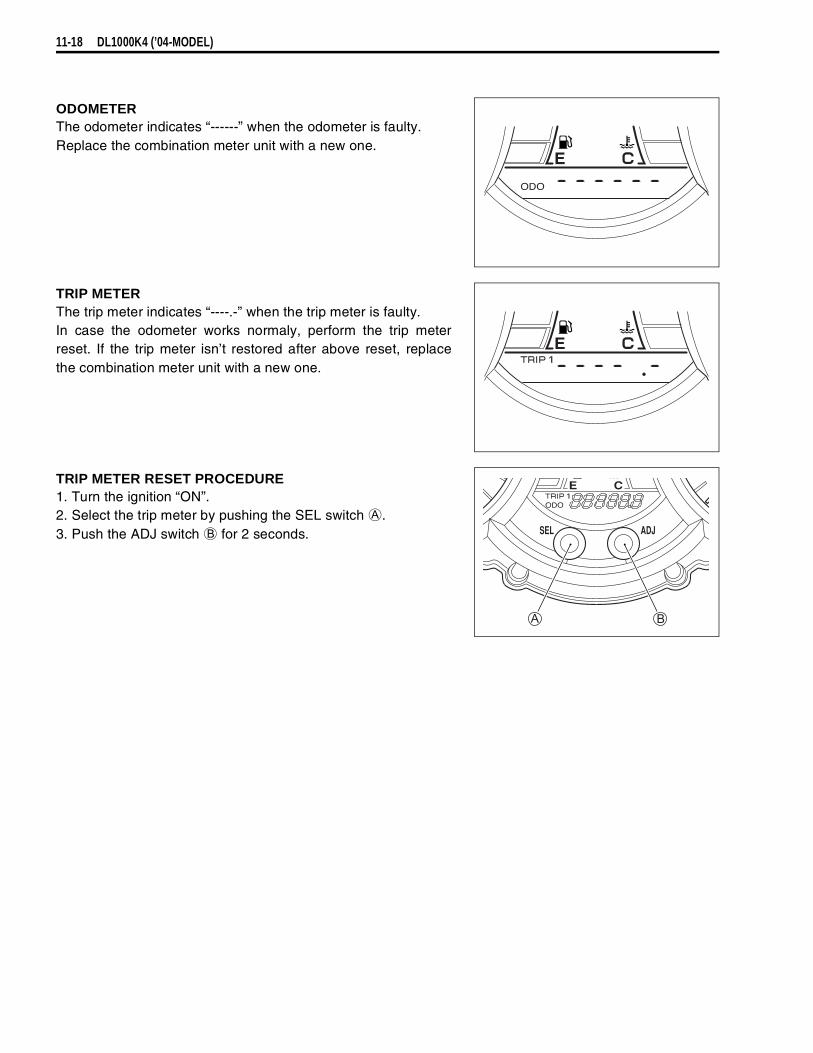
11-18 DL1000K4 (’04-MODEL)
ODOMETERThe odometer indicates “------” when the odometer is faulty.Replace the combination meter unit with a new one.
TRIP METERThe trip meter indicates “----.-” when the trip meter is faulty.In case the odometer works normaly, perform the trip meterreset. If the trip meter isn’t restored after above reset, replacethe combination meter unit with a new one.
TRIP METER RESET PROCEDURE1. Turn the ignition “ON”.2. Select the trip meter by pushing the SEL switch
.3. Push the ADJ switch
for 2 seconds.
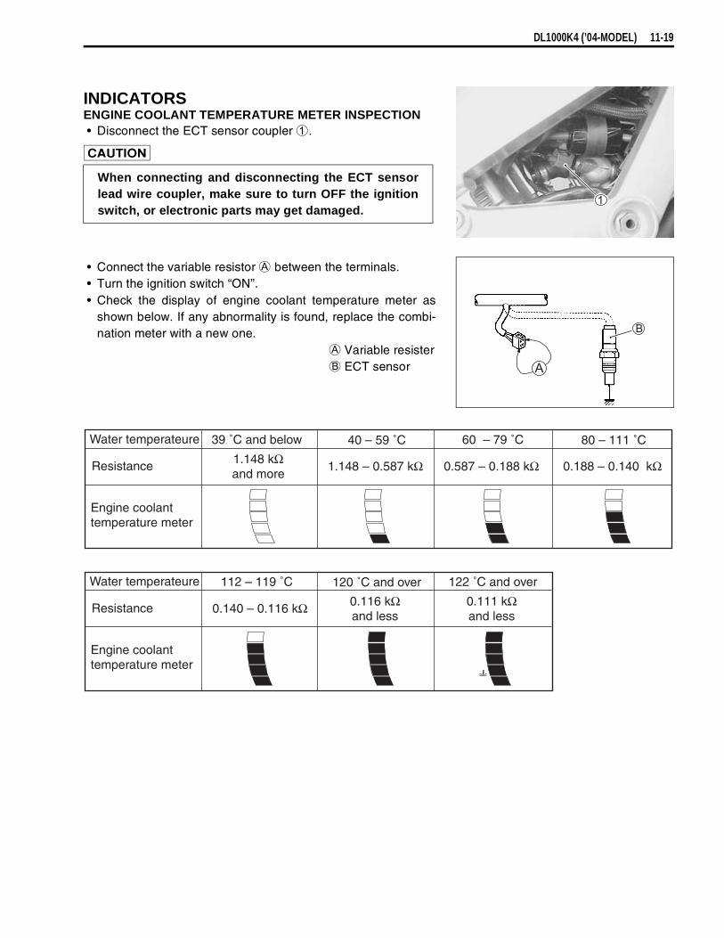
DL1000K4 (’04-MODEL) 11-19
INDICATORSENGINE COOLANT TEMPERATURE METER INSPECTION• Disconnect the ECT sensor coupler
.
• Connect the variable resistor
between the terminals.• Turn the ignition switch “ON”.• Check the display of engine coolant temperature meter as
shown below. If any abnormality is found, replace the combi-nation meter with a new one.
Variable resister
ECT sensor
When connecting and disconnecting the ECT sensorlead wire coupler, make sure to turn OFF the ignitionswitch, or electronic parts may get damaged.
Resistance 1.148 kΩand more
1.148 – 0.587 kΩ 0.587 – 0.188 kΩ 0.188 – 0.140 kΩ
Engine coolanttemperature meter
Water temperateure 39 ˚C and below 40 – 59 ˚C 60 – 79 ˚C 80 – 111 ˚C
Resistance 0.140 – 0.116 kΩ
Engine coolanttemperature meter
Water temperateure 112 – 119 ˚C 120 ˚C and over 122 ˚C and over
0.116 kΩand less
0.111 kΩand less
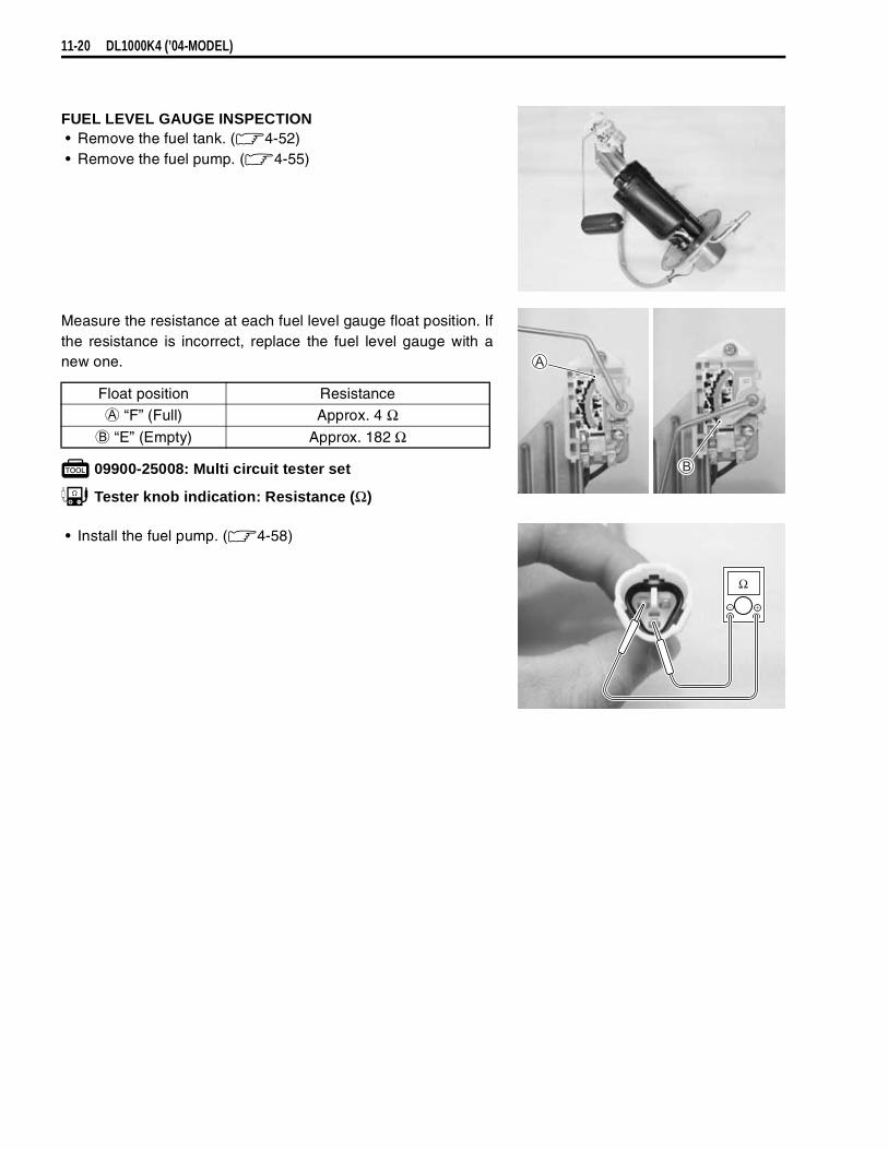
11-20 DL1000K4 (’04-MODEL)
FUEL LEVEL GAUGE INSPECTION• Remove the fuel tank. ( 4-52)• Remove the fuel pump. ( 4-55)
Measure the resistance at each fuel level gauge float position. Ifthe resistance is incorrect, replace the fuel level gauge with anew one.
09900-25008: Multi circuit tester set
Tester knob indication: Resistance (Ω)
• Install the fuel pump. ( 4-58)
Float position Resistance
“F” (Full) Approx. 4 Ω
“E” (Empty) Approx. 182 Ω
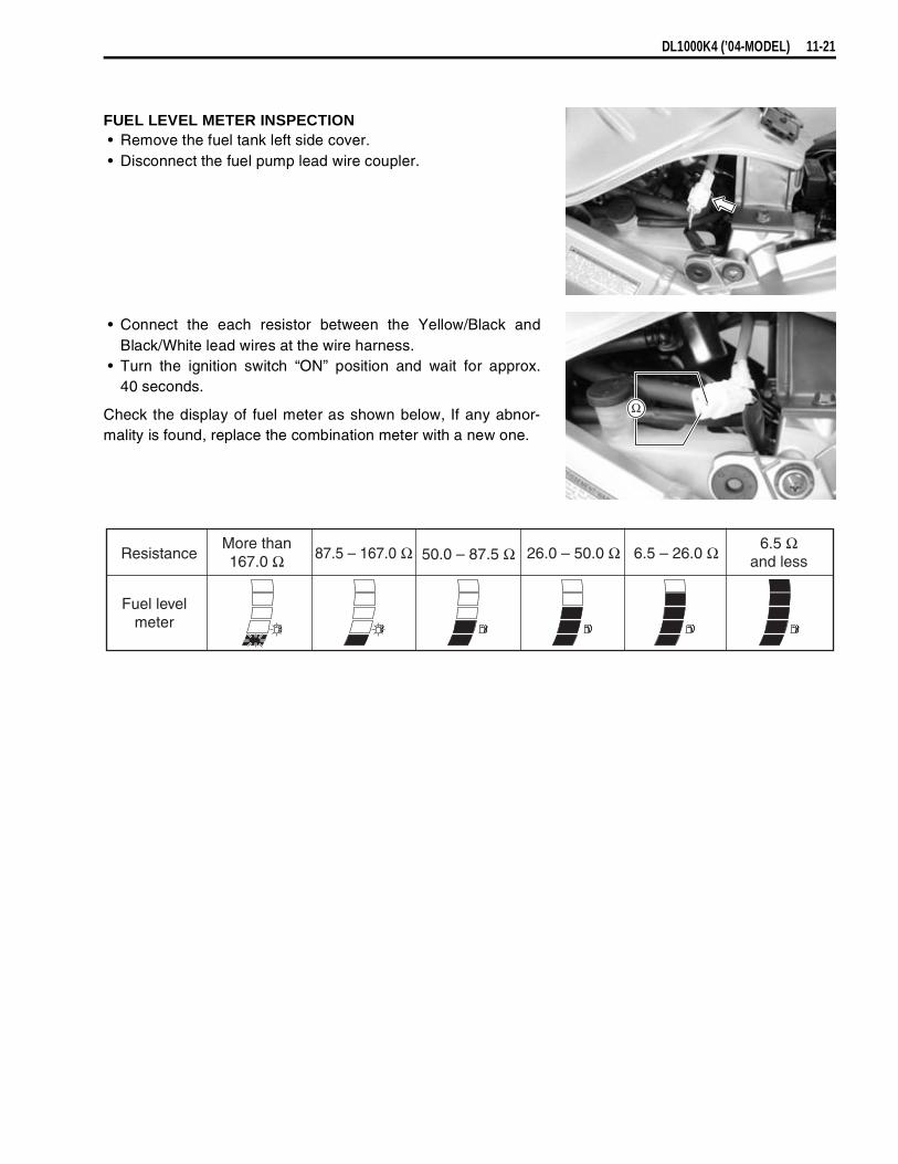
DL1000K4 (’04-MODEL) 11-21
FUEL LEVEL METER INSPECTION• Remove the fuel tank left side cover.• Disconnect the fuel pump lead wire coupler.
• Connect the each resistor between the Yellow/Black andBlack/White lead wires at the wire harness.
• Turn the ignition switch “ON” position and wait for approx.40 seconds.
Check the display of fuel meter as shown below, If any abnor-mality is found, replace the combination meter with a new one.
ResistanceMore than167.0 Ω
6.5 Ωand less87.5 – 167.0 Ω 50.0 – 87.5 Ω 26.0 – 50.0 Ω 6.5 – 26.0 Ω
Fuel levelmeter
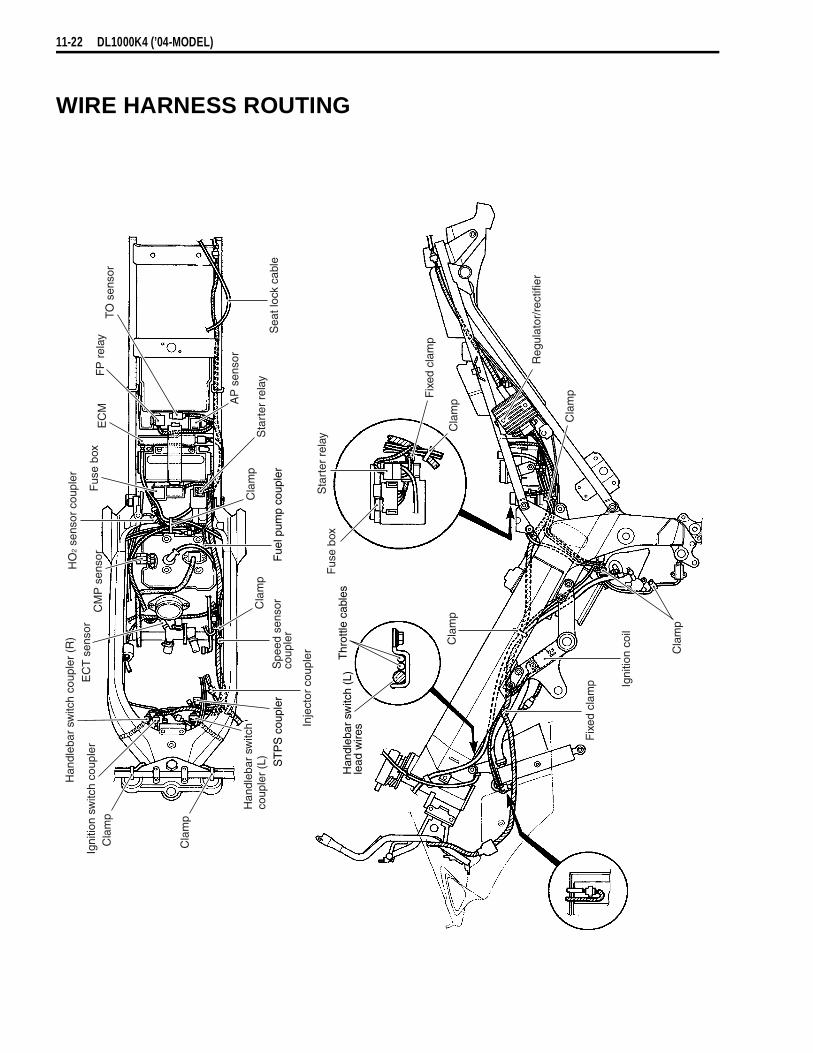
11-22 DL1000K4 (’04-MODEL)
WIRE HARNESS ROUTING
Sta
rter
rel
ayF
use
box
Reg
ulat
or/r
ectif
ier
Cla
mp
Cla
mp
Cla
mp
Cla
mp
Han
dleb
ar s
witc
hco
uple
r (L
)
Inje
ctor
cou
pler
ST
PS
cou
pler
Cla
mp
Spe
ed s
enso
rco
uple
rF
uel p
ump
coup
ler
Cla
mp
Sta
rter
rel
ay
AP
sen
sor
Sea
t loc
k ca
ble
TO s
enso
rF
P r
elay
EC
MF
use
box
HO
2 se
nsor
cou
pler
CM
P s
enso
rE
CT
sen
sor
Han
dleb
ar s
witc
h co
uple
r (R
)
Igni
tion
switc
h co
uple
r Fix
ed c
lam
p Igni
tion
coil
Cla
mpFix
ed c
lam
p
Thr
ottle
cab
les
Han
dleb
ar s
witc
h (L
)le
ad w
ires
Cla
mp

DL1000K4 (’04-MODEL) 11-23
Fixed clamp
Fixed clamp
Clamp
Headlight
Clamp
HO2 sensor
Clamp
IAT sensor
IAP sensor
CMP sensor
Fixed clamp
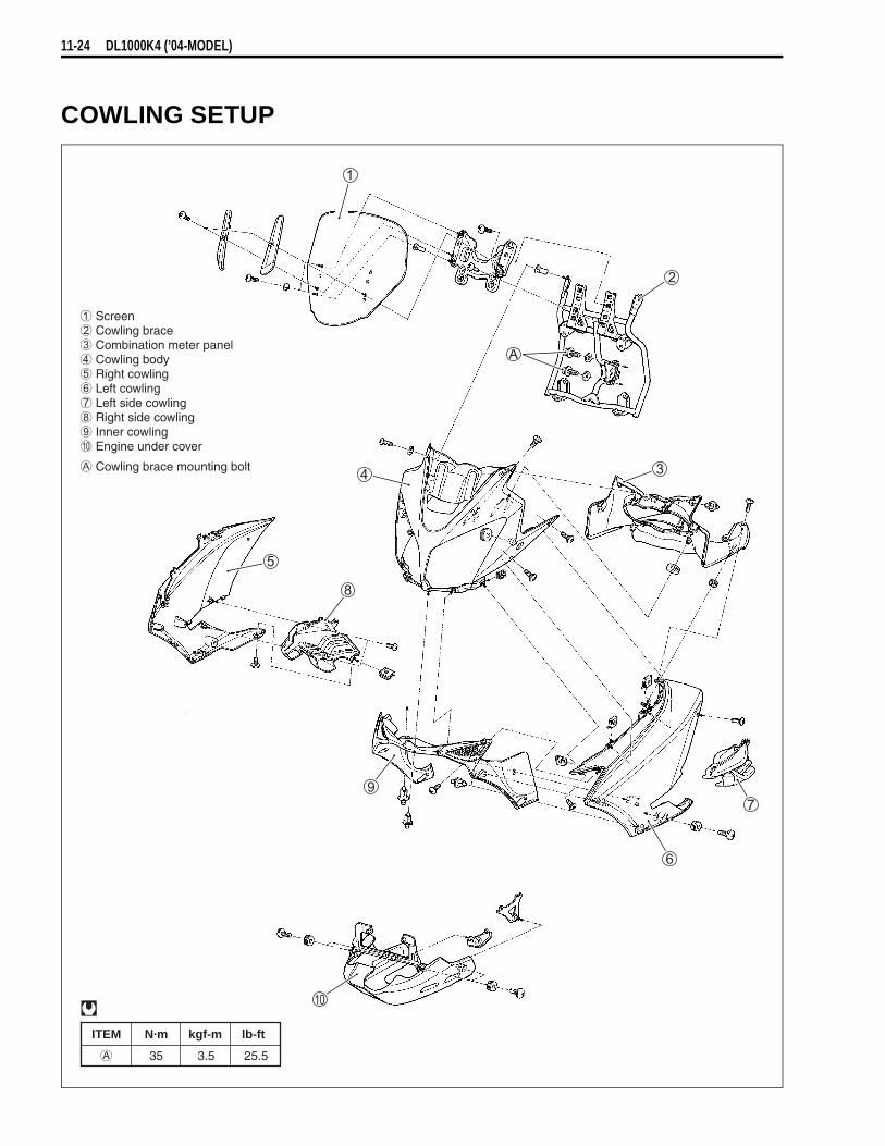
11-24 DL1000K4 (’04-MODEL)
COWLING SETUP
ITEM N·m kgf-m lb-ft
35 3.5 25.5
Screen Cowling brace Combination meter panel Cowling body Right cowling Left cowling Left side cowling Right side cowling Inner cowling Engine under cover
Cowling brace mounting bolt

12
WIRING DIAGRAMFI SYSTEM WIRING DIAGRAM
BATTERY
ECM
IGNITION COIL30 A 15 A
15 A
IG2 IG1
MAINSWITCH
NEUTRALLAMP
SIDE-STANDRELAY
ENGINE STOPSWITCH
FUEL PUMP RELAY
FUEL PUMP
STARTERBUTTON
STARTERRELAY
CMPS
IATSTS
STPS
ECTS
CKPSCKPS
TPS
TIP OVER SENSOR
FIFI
IATS
CKPS
FI
FI : FUEL INJECTORSTPS : SECONDARY THROTTLE POSITION SENSORECTS : ENGINE COOLANT TEMP. SENSORTPS : THROTTLE POSITION SENSORIATS : INTAKE AIR TEMP. SENSORCMPS : CAMSHAFT POSITION SENSORCKPS : CRANKSHAFT POSITION SENSOR
HO2 SENSOR
CLUTCHLEVERPOSITIONSWITCH
GEARPOSITIONSWITCH
SIDE-STANDSWITCH
PAIR SOLENOIDCONTROL VALVEINTAKE AIR
PRESSURESENSOR
SPEEDOMETER
ATMOSPHERICPRESSURE
SENSOR
MODE SELECTION SWITCH
Y/BY/B
Br/WBr/WO/RO/R
O/WO/WB/YB/YB
W/BlW/BlY/RY/RB/BlB/Bl
BrBrGr/WGr/WGr/BGr/BY/GY/GB/RB/RR/BR/BDgDg
RP/WP/WB/BrB/Br
YW/BW/BW/GW/GY/WY/W
PG
G/BlG/Bl
W/RW/R
G/BG/BG/YG/YBr/BBr/BB/GB/G
B/WB/WB/WB/WB/WB/WB/WB/W
Y/B
Br/WO/R
O/WB/YB
W/BlY/RB/Bl
BrGr/WGr/BY/GB/RR/BDg
RP/WB/Br
YW/BW/GY/W
PG
G/Bl
W/R
G/BG/YBr/BB/G
B/WB/WB/WB/W
V FP
a DONW AT
E +BH CLT1 IG1
2 IG2
R VMZ THW
7 SOL5 FI #16 FI #2K STA
J MO +L MO –D THA
0 VCCI TPSX E2
d STPS8 HO2 (OXH)N HO2 (OX)
B G+
U GPP N +T N –
] TS
F PMG PA
4 TACO[ TECH
^ NT3COY
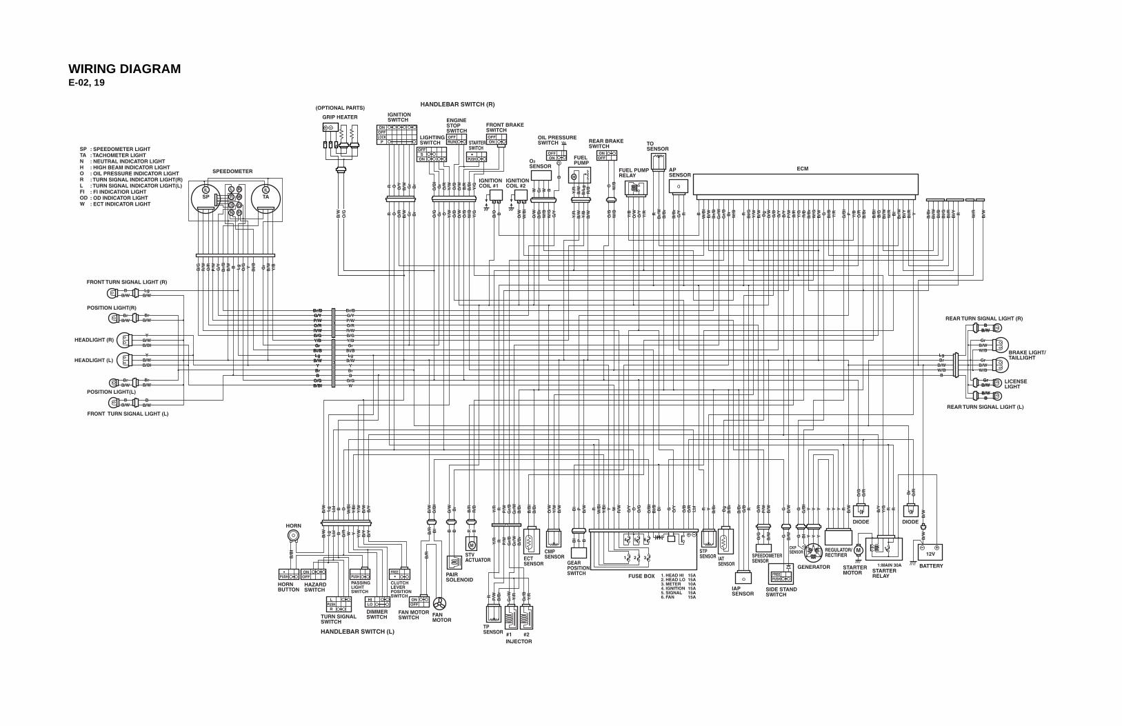
WIRING DIAGRAME-02, 19
B/G
R/W
O/R
P/W G/Y
Br/
BB
/W B Lg
O/G Y
Bl/B Gr
B/W Y/B
R O O/Y
B/W Gr
Br
O/B
lG
rO
/RY
/WO
/BO
/WB
/RB
/Bl
Y/G
R O O/R
B/W Gr
Br
B/O B
O/W
W/B
l
O/W
B/B
rW
/BW
/GG
/Y
O/G
W/B
Y/B
O/W
O/Y
Y/R R
Br/
WB
/Br
B/B
rG
/Y R BW
/Bl
B/W
Br/
BG
r/W
Gr/
BB
rW
/B RB
l/GY
/WB
/W Dg
O/W
O/B
G/Y
B/Y
P/W B/R
Y/G
R/B
B/B
rW
/GB
/W GB
l/B Y/R
G/B
lP Y/B
O/R
B/B
r
B/B
lB
/GB
l/W W/R Bl
Br/
WB
l/YB
l/R Y
B/B
rB
l/WB
l/BB
l/GB
l/RB
l/Y R
W/R
B/W
W Gr
W B
O W/B
Y/R
B/W
B/L
gR
/B
Y/R
B/W Y/B
B/W
B
O/G Gr O Y
/WO
/BO
/WO
/GW
/BY
/G
LgBr
B/WW/B
B
GrB/WW/B
GrB/WW/B
BB/W
LgB/W
BrB/W
YB/WB/Bl
Br/BG/YP/WO/RR/WB/OY/BGr
Bl/BLg
B/WYBrB
O/GW
YB/WB/Bl
BrB/W
BB/W
BrB/W
BrB/W
BB/W
B/W Lg
Lb
lB O
W/B
lY
/Bl
Y/W
B/W B/Y
B/W
O/B
l
O/W Br
B/R
R/B
Y/R R P/W
Gr/
BG
r/W
B/B
r
B/B
lB
/Br
O/W
Y/W
B/W Bl P
B/W R
W/B
lY
/Bl
Y W R/W
O/Y O O/G
O/B
lB
l/B Bl
G O/Y
O/B
O/R
Lb
l
R YB
/Br
Dg
B/B
r
B/B
rG
/B R O/R
P/W
B/W G B/W G
G/B
lY Y Y Y Y Y R
B/W B/Y
Y/G R R
B/W
B/W
Br
O/R
O/G
O/R
O/G P
B/W G B/W G Bl Y Y Y
Bl P BY
/R R P/W
Gr/
BG
r/W
B/B
r
R P/W
B/B
r
Gr/
WY
/R
Gr/
BY
/R
B BB/R Bl
B/R
B/B
l
B/W Lg
Lb
lB O/R W Y
Y/W B/Y
B/Y
B/G
R/W
O/R
P/W G/Y
Br/
BB
/W B Lg
O/G Y
Bl/B Gr
B/W Y/B
R O O/Y
B/W Gr
Br
O/B
lG
rO
/RY
/WO
/BO
/WB
/RB
/Bl
Y/G
R O O/R
B/W Gr
Br
B/O B
O/W
W/B
l
O/W
B/B
rW
/BW
/GG
/Y
O/G
W/B
Y/B
O/W
O/Y
Y/R R
Br/
WB
/Br
B/B
rG
/Y R BW
/Bl
B/W
Br/
BG
r/W
Gr/
BB
rW
/B RB
l/GY
/WB
/W Dg
O/W
G/B
G/Y
B/Y
P/W B/R
Y/G
R/B
B/B
rW
/GB
/W GB
l/B Y/R
G/B
lP Y/B
O/R
B/B
r
B/B
lB
/GB
l/W W/R Bl
Br/
WB
l/YB
l/R Y
B/B
rB
l/WB
l/BB
l/GB
l/RB
l/Y R
W/R
B/W
W Gr
W B
O W/B
Y/R
B/W
B/L
gR
/B
Y/R
B/W Y/B
B/W
B
O/G Gr O Y
/WO
/BO
/WO
/GW
/BY
/G
LgBr
B/WW/B
B
B/WB
B/WB
GrB/WW/B
GrB/WW/B
BB/W
LgB/W
BrB/W
YB/WB/Bl
Br/BG/YP/WO/RR/WB/GY/BGr
Bl/BLg
B/WYBrB
O/GW
YB/WB/Bl
BrB/W
BB/W
BrB/W
BrB/W
BB/W
B/W Lg
Lb
lB O
W/B
lY
/Bl
Y/W
B/W B/Y
B/W
O/B
l
O/W Br
B/R
R/B
Y/R R P/W
Gr/
BG
r/W
B/B
r
B/B
lB
/Br
O/W
Y/W
B/W Bl P
B/W R
W/B
lY
/Bl
Y W R/W
O/Y O O/G
O/B
lB
l/B Bl
G O/Y
O/B
O/R
Lb
l
R YB
/Br
Dg
B/B
r
B/B
rG
/B R O/R
P/W
B/W G B/W G
G/B
lY Y Y Y Y Y R
B/W B/Y
Y/G R R
B/W
B/W
Br
O/R
O/G
O/R
O/G P
B/W G B/W G Bl Y Y Y
Bl P BY
/R R P/W
Gr/
BG
r/W
B/B
r
R P/W
B/B
r
Gr/
WY
/R
Gr/
BY
/R
B BB/R Bl
B/R
B/B
l
B/W Lg
Lb
lB O/R W Y
Y/W B/Y
B/Y
Br/BG/YP/WO/RR/WB/GY/BGr
Bl/BLg
B/WYBrB
O/GB/Bl
Br/BG/YP/WO/RR/WB/GY/BGr
Bl/BLg
B/WYBrB
O/GB/Bl
GrB/WGr
B/W
BB/W
BB/W
SP TA
ONOFFLOCK
P
OFFS
ON
OFFRUN
PUSH
OFFON
OFFON
IL ILL
FI
OD
N
R
W
O
H
ONOFF
M
FREEPUSH
ONOFF
FREEPUSHPUSH
LPUSH
R
HILO
ONOFF
SPTANHORLFIODW
: SPEEDOMETER LIGHT: TACHOMETER LIGHT: NEUTRAL INDICATOR LIGHT: HIGH BEAM INDICATOR LIGHT: OIL PRESSURE INDICATOR LIGHT: TURN SIGNAL INDICATOR LIGHT(R): TURN SIGNAL INDICATOR LIGHT(L): FI INDICATIOR LIGHT: OD INDICATOR LIGHT: ECT INDICATOR LIGHT
SPEEDOMETER
HEADLIGHT (R)
HEADLIGHT (L)
FRONT TURN SIGNAL LIGHT (R)
FRONT TURN SIGNAL LIGHT (L)
POSITION LIGHT(R)
POSITION LIGHT(L)
HANDLEBAR SWITCH (R)
REAR BRAKESWITCH
IGNITIONCOIL #2
IGNITIONCOIL #1
IGNITIONSWITCH
LIGHTINGSWITCH
ENGINE STOPSWITCH
FRONT BRAKESWITCH
STARTERSWITCH
O2 SENSOR ECM
FUELPUMP
OIL PRESSURESWITCH TO
SENSOR
APSENSOR
FUEL PUMPRELAY
BRAKE LIGHT/TAILLIGHT
REAR TURN SIGNAL LIGHT (R)
REAR TURN SIGNAL LIGHT (L)
LICENSELIGHT
BATTERY1:MAIN 30A STARTER MOTOR STARTER
RELAY
1
FUSE BOX 1. HEAD HI2. HEAD LO3. METER4. IGNITION5. SIGNAL6. FAN
15A15A10A15A15A15A
DIODE DIODE
REGULATOR/RECTIFIER
GENERATOR
SIDE STANDSWITCH
SPEEDOMETERSENSOR
IAPSENSOR
IATSENSOR
STPSENSOR1 2 3
4 5 6
ECTSENSOR
TP SENSOR
INJECTOR#1 #2
GEARPOSITIONSWITCH
CMPSENSOR
FANMOTOR
FAN MOTORSWITCH
STVACTUATOR
PAIRSOLENOID
CLUTCHLEVERPOSITIONSWITCH
DIMMERSWITCHTURN SIGNAL
SWITCH
PASSINGLIGHTSWITCH
HORNBUTTON
HANDLEBAR SWITCH (L)
HAZARDSWITCH
HORN
CKPSENSOR
GRIP HEATER
B/W
O/G
R B
(OPTIONAL PARTS)

E-03, 28, 33
R O O/Y
B/W
Gr
B
rR O O/Y
B/W
Gr
B
r
B/G
R/W
O/R
P/W G/Y
Br/
BB
/W B Lg
O/G Y
Bl/B
O/G
B/W Y/B
O/B
O/W
B/R
B/B
lY
/G
R O O/R
B/W Gr
Br
B/O B
O/W
W/B
l
G/Y
O/G
W/B
Y/B
O/W
O/Y
Y/R R
Br/
WB
/Br
B/B
rG
/Y R BW
/Bl
B/W
Br/
BG
r/W
Gr/
B
RB
l/GY
/WB
/W Dg
O/W
O/B
G/Y
B/Y
P/W B/R
Y/G
R/B
B/B
r
B/W G
Bl/B Y/R
G/B
lP Y/B
O/R
B/B
r
B/B
lB
/GB
l/W W/R Bl
Br/
WB
l/YB
l/R Y
B/B
rB
l/WB
l/BB
l/GB
l/RB
l/Y R
W/R
B/W
O W/B
Y/R
B/W
B/L
gR
/B
Y/R
B/W Y/B
B/WO/B
O/W
O/G
W/B
Y/G
LgBr
B/WW/B
B
GrB/WW/B
GrB/WW/B
BB/W
LgB/W
YB/WB/Bl
Br/BG/YP/WO/RR/WB/OY/BO/GBl/BLg
B/WYWB
YB/WB/Bl
BB/W
BB/W
B/W Lg
Lb
lB O
W/B
lY
/Bl
W B/W B/Y
B/W
O/B
l
B/R
R/B
Y/R R P/W
Gr/
BG
r/W
B/B
r
B/B
lB
/Br
O/W
Y/W
B/W Bl P
B/W R
W/B
lY
/Bl
Y W R/W
O/Y O O/G
O/B
lB
l/B Bl
G O/Y
O/B
O/R
Lb
l
R YB
/Br
Dg
B/B
r
B/B
rG
/B R O/R
P/W
B/W G B/W G
G/B
lY Y Y Y Y Y R
B/W B/Y
Y/G R R
B/W
B/W
O/G P
B/W G B/W G Bl Y Y Y
Bl P BY
/R R P/W
Gr/
BG
r/W
B/B
r
R P/W
B/B
r
Gr/
WY
/R
Gr/
BY
/R
B/R Bl
B/R
B/B
l
B/W Lg
Lb
lB O/R W Y
Y/W B/Y
B/Y
B/W Lg
Lb
lB O
W/B
lY
/Bl
O B/W B/Y
B/G
R/W
O/R
P/W G/Y
Br/
BB
/W B Lg
O/G Y
Bl/B
O/G
B/W Y/B
O/B
O/W
B/R
B/B
lY
/G
R O O/R
B/W
O/G Br
B/O B
O/W
W/B
l
G/Y
O/G
W/B
Y/B
O/W
O/Y
Y/R R
Br/
WB
/Br
B/B
rG
/Y R BW
/Bl
B/W
Br/
BG
r/W
Gr/
B
RB
l/GY
/WB
/W Dg
O/W
G/B
G/Y
B/Y
P/W B/R
Y/G
R/B
B/B
r
B/W G
Bl/B Y/R
G/B
lP Y/B
O/R
B/B
r
B/B
lB
/GB
l/W W/R Bl
Br/
WB
l/YB
l/R Y
B/B
rB
l/WB
l/BB
l/GB
l/RB
l/Y R
W/R
B/W
O W/B
Y/R
B/W
B/L
gR
/B
Y/R
B/W Y/B
B/WO/B
O/W
O/G
W/B
Y/G
LgBr
B/WW/B
B
B/WB
B/WB
GrB/WW/B
GrB/WW/B
BB/W
LgB/W
YB/WB/Bl
Br/BG/YP/WO/RR/WB/GY/BO/GBl/BLg
B/WYWB
YB/WB/Bl
BB/W
BB/W
B/W
O/B
l
B/R
R/B
Y/R R P/W
Gr/
BG
r/W
B/B
r
B/B
lB
/Br
O/W
Y/W
B/W Bl P
B/W R
W/B
lY
/Bl
Y W R/W
O/Y O O/G
O/B
lB
l/B Bl
G O/Y
O/B
O/G
Lb
l
R YB
/Br
Dg
B/B
r
B/B
rG
/B R O/R
P/W
B/W G B/W G
G/B
lY Y Y Y Y Y R
B/W B/Y
Y/G R R
B/W
B/W
O/G P
B/W G B/W G Bl Y Y Y
Bl P BY
/R R P/W
Gr/
BG
r/W
B/B
r
R P/W
B/B
r
Gr/
WY
/R
Gr/
BY
/R
B/R Bl
B/R
B/B
l
B/W Lg
Lb
lB O/R W Y
Y/W B/Y
B/Y
Br/BG/YP/WO/RR/WB/GY/BO/GBl/BLg
B/WY
B/BlB
Br/BG/YP/WO/RR/WB/GY/BO/GBl/BLg
B/WY
B/BlB
GrB/WGr
B/W
BB/W
BB/W
SP TA
ONOFFLOCK
POFFRUN
PUSH
OFFON
OFFON
IL ILL
FI
OD
N
R
W
O
H
ONOFF
M
FREEPUSH
ONOFF
FREEPUSH
LPUSH
R
HILO
SPEEDOMETER
HEADLIGHT (R)
HEADLIGHT (L)
FRONT TURN SIGNAL LIGHT (R)
FRONT TURN SIGNAL LIGHT (L)
HANDLEBAR SWITCH (R)
REAR BRAKESWITCH
IGNITIONCOIL #2
IGNITIONCOIL #1
IGNITIONSWITCH ENGINE
STOPSWITCH
FRONT BRAKESWITCH
STARTERSWITCH
ECM
FUELPUMP
OIL PRESSURESWITCH TO
SENSOR
APSENSOR
FUEL PUMPRELAY
BRAKE LIGHT/TAILLIGHT
REAR TURN SIGNAL LIGHT (R)
REAR TURN SIGNAL LIGHT (L)
LICENSELIGHT
BATTERY1:MAIN 30A STARTER MOTOR STARTER
RELAY
1
FUSE BOX 1. HEAD HI2. HEAD LO3. METER4. IGNITION5. SIGNAL6. FAN
15A15A10A15A15A15A
REGULATOR/RECTIFIER
GENERATOR
SIDE STANDSWITCH
SPEEDOMETERSENSOR
IAPSENSOR
IATSENSOR
STPSENSOR1 2 3
4 5 6
ECTSENSOR
TP SENSOR
INJECTOR#1 #2
GEARPOSITIONSWITCH
CMPSENSOR
FANMOTOR
FAN MOTORSWITCH
STVACTUATOR
CLUTCHLEVERPOSITIONSWITCH
DIMMERSWITCHTURN SIGNAL
SWITCH
HORNBUTTON
HANDLEBAR SWITCH (L)
HORN
CKPSENSOR
SPTANHORLFIODW
: SPEEDOMETER LIGHT: TACHOMETER LIGHT: NEUTRAL INDICATOR LIGHT: HIGH BEAM INDICATOR LIGHT: OIL PRESSURE INDICATOR LIGHT: TURN SIGNAL INDICATOR LIGHT(R): TURN SIGNAL INDICATOR LIGHT(L): FI INDICATIOR LIGHT: OD INDICATOR LIGHT: ECT INDICATOR LIGHT
GRIP HEATER
R B
B/W
O/G
(OPTIONAL PARTS)

E-24
B/G
R/W
O/R
P/W G/Y
Br/
BB
/W B Lg
O/G Y
Bl/B
O/G
B/W Y/B
O/B
O/W
B/R
B/B
lY
/G
R O O/R
B/W Gr
Br
B/O B
O/W
W/B
l
G/Y
O/G
W/B
Y/B
O/W
O/Y
Y/R R
Br/
WB
/Br
B/B
rG
/Y R BW
/Bl
B/W
Br/
BG
r/W
Gr/
B
RB
l/GY
/WB
/W Dg
O/W
O/B
G/Y
B/Y
P/W B/R
Y/G
R/B
B/B
r
B/W G
Bl/B Y/R
G/B
lP Y/B
O/R
B/B
r
B/B
lB
/GB
l/W W/R Bl
Br/
WB
l/YB
l/R Y
B/B
rB
l/WB
l/BB
l/GB
l/RB
l/Y R
W/R
B/W
O W/B
Y/R
B/W
B/L
gR
/B
Y/R
B/W Y/B
B/WO/B
O/W
O/G
W/B
Y/G
LgBr
B/WW/B
B
GrB/WW/B
GrB/WW/B
BB/W
LgB/W
YB/WB/Bl
Br/BG/YP/WO/RR/WB/OY/BO/GBl/BLg
B/WYWB
YB/WB/Bl
BB/W
BB/W
B/W Lg
Lb
lB O
W/B
lY
/Bl
/W B/W B/Y
B/W
O/B
l
B/R
R/B
Y/R R P/W
Gr/
BG
r/W
B/B
r
B/B
lB
/Br
O/W
Y/W
B/W Bl P
B/W R
W/B
lY
/Bl
Y W R/W
O/Y O O/G
O/B
lB
l/B Bl
G O/Y
O/B
O/R
Lb
l
R YB
/Br
Dg
B/B
r
B/B
rG
/B R O/R
P/W
B/W G B/W G
G/B
lY Y Y Y Y Y R
B/W B/Y
Y/G R R
B/W
B/W
O/G P
B/W G B/W G Bl Y Y Y
Bl P BY
/R R P/W
Gr/
BG
r/W
B/B
r
R P/W
B/B
r
Gr/
WY
/R
Gr/
BY
/R
B/R Bl
B/R
B/B
l
B/W Lg
Lb
lB O/R W Y
Y/W B/Y
B/Y
B/G
R/W
O/R
P/W G/Y
Br/
BB
/W B Lg
O/G Y
Bl/B
O/G
B/W Y/B
O/B
O/W
B/R
B/B
lY
/G
R O O/R
B/W
O/G Br
B/O B
O/W
W/B
l
G/Y
O/G
W/B
Y/B
O/W
O/Y
Y/R R
Br/
WB
/Br
B/B
rG
/Y R BW
/Bl
B/W
Br/
BG
r/W
Gr/
B
RB
l/GY
/WB
/W Dg
O/W
G/B
G/Y
B/Y
P/W B/R
Y/G
R/B
B/B
r
B/W G
Bl/B Y/R
G/B
lP Y/B
O/R
B/B
r
B/B
lB
/GB
l/W W/R Bl
Br/
WB
l/YB
l/R Y
B/B
rB
l/WB
l/BB
l/GB
l/RB
l/Y R
W/R
B/W
O W/B
Y/R
B/W
B/L
gR
/B
Y/R
B/W Y/B
B/WO/B
O/W
O/G
W/B
Y/G
LgBr
B/WW/B
B
B/WB
B/WB
GrB/WW/B
GrB/WW/B
BB/W
LgB/W
YB/WB/Bl
Br/BG/YP/WO/RR/WB/GY/BO/GBl/BLg
B/WYWB
YB/WB/Bl
BB/W
BB/W
B/W Lg
Lb
lB O
W/B
lY
/Bl
O B/W B/Y
B/W
O/B
l
B/R
R/B
Y/R R P/W
Gr/
BG
r/W
B/B
r
B/B
lB
/Br
O/W
Y/W
B/W Bl P
B/W R
W/B
lY
/Bl
Y W R/W
O/Y O O/G
O/B
lB
l/B Bl
G O/Y
O/B
O/G
Lb
l
R YB
/Br
Dg
B/B
r
B/B
rG
/B R O/R
P/W
B/W G B/W G
G/B
lY Y Y Y Y Y R
B/W B/Y
Y/G R R
B/W
B/W
O/G P
B/W G B/W G Bl Y Y Y
Bl P BY
/R R P/W
Gr/
BG
r/W
B/B
r
R P/W
B/B
r
Gr/
WY
/R
Gr/
BY
/R
B/R Bl
B/R
B/B
l
B/W Lg
Lb
lB O/R W Y
Y/W B/Y
B/Y
Br/BG/YP/WO/RR/WB/GY/BO/GBl/BLg
B/WY
B/BlB
Br/BG/YP/WO/RR/WB/GY/BO/GBl/BLg
B/WY
B/BlB
R O O/Y
B/W
Gr
R O O/Y
B/W
Gr
BB/W
BB/W
GrB/WGr
B/W
SP TA
ONOFFLOCK
OFFRUN
PUSH
OFFON
OFFON
IL ILL
FI
OD
N
R
W
O
H
ONOFF
M
FREEPUSH
ONOFF
FREEPUSHPUSH
LPUSH
R
HILO
SPEEDOMETER
HEADLIGHT (R)
HEADLIGHT (L)
FRONT TURN SIGNAL LIGHT (R)
FRONT TURN SIGNAL LIGHT (L)
HANDLEBAR SWITCH (R)
REAR BRAKESWITCH
IGNITIONCOIL #2
IGNITIONCOIL #1
IGNITIONSWITCH
ENGINE STOPSWITCH
FRONT BRAKESWITCH
STARTERSWITCH
ECM
FUELPUMP
OIL PRESSURESWITCH TO
SENSOR
APSENSOR
FUEL PUMPRELAY
BRAKE LIGHT/TAILLIGHT
REAR TURN SIGNAL LIGHT (R)
REAR TURN SIGNAL LIGHT (L)
LICENSELIGHT
BATTERY1:MAIN 30A STARTER MOTOR STARTER
RELAY
1
FUSE BOX 1. HEAD HI2. HEAD LO3. METER4. IGNITION5. SIGNAL6. FAN
15A15A10A15A15A15A
REGULATOR/RECTIFIER
GENERATOR
SIDE STANDSWITCH
SPEEDOMETERSENSOR
IAPSENSOR
IATSENSOR
STPSENSOR1 2 3
4 5 6
ECTSENSOR
TP SENSOR
INJECTOR#1 #2
GEARPOSITIONSWITCH
CMPSENSOR
FANMOTOR
FAN MOTORSWITCH
STVACTUATOR
CLUTCHLEVERPOSITIONSWITCH
DIMMERSWITCHTURN SIGNAL
SWITCH
PASSINGLIGHTSWITCH
HORNBUTTON
HANDLEBAR SWITCH (L)
HORN
CKPSENSOR
SPTANHORLFIODW
: SPEEDOMETER LIGHT: TACHOMETER LIGHT: NEUTRAL INDICATOR LIGHT: HIGH BEAM INDICATOR LIGHT: OIL PRESSURE INDICATOR LIGHT: TURN SIGNAL INDICATOR LIGHT(R): TURN SIGNAL INDICATOR LIGHT(L): FI INDICATIOR LIGHT: OD INDICATOR LIGHT: ECT INDICATOR LIGHT
GRIP HEATER
B/W
O/G
R B
(OPTIONAL PARTS)

MODEL APPLICATION
Year Model Beginning Frame No.
2004 LV1000-A1 JSKBS112100100001 or JSKBS112200100001
Part No. 99924-1335-01 Printed in Japan