klaro e pro 15 sbr awts home sewage system · 2016-04-28 · connected to tank dome white hose...
TRANSCRIPT
1
KLARO E Pro 15 SBR AWTS Home Sewage System
Installation Manual
Graf Australia Pty Ltd
2, 8 Piper Street
Caboolture Qld 4510 Phone: 1300 466 469
[email protected] www.klaro.au
Issued: June 2015 InstallManv15.4


Klaro EPro15 Installation Manual – klaro.com.au – V15,1
KLARO GmbH 1
Contents Page no.
1. General Notes 2 2. Specification of the tanks 3 3. Installation 4
I. Site preparation II. Installation requirements 5
III. Groundwater IV. Slope or embankment V. Trafficable Sites 6
4. Installing the Tanks 6 I. Re-check II. Backfilling
5. Technical Assembly 7 I. Connection of Piping
6. Assembly of telescopic Dome/Lid 8 I. Connection of Piping II. Assembly of the Extension Riser
7. Filling with Water 9 8. Air Hoses 10 9. Installation of Control Cabinet 11 10. Commissioning 13
KLARO EPro15
(Illustrated without pump chamber)
Advanced home sewage system

KLARO Installation Manual V15.1
2
1. General Notes
Thank you for choosing a Graf KLARO SBR Wastewater Treatment System. Our Company Philosophy is to deliver systems that offer Maximum Operating Efficiency and Reliability. Please read this manual carefully prior to installing your system to achieve the best result.
1.1. Warranty The instructions in this manual must be observed at all times. Non compliance may void any warranty claim. Please check all components for damage prior to assembly or installation. Installation is to be carried out by a certified and trained Graf Australia Klaro Certified Agent.
1.2. Safety All relevant regulations and standards must be observed when carrying out installation, assembly, maintenance and repairs. When carrying out any work on the plant or parts of it, the entire plant must be isolated and secured against unauthorised switching back on. The tank lid must always be closed, except when working in the tank, which must be emptied before entering. OBSERVE all confined space regulations. Only use original Graf KLARO components and parts. The use of non Graf Klaro Components may impair the functionality of the plant and void all liability for any resulting damage. WARNING: Electrical: All electrical work has to be carried our by a licensed electrician. Excavation: Always check and obtain all underground service information prior to commencement and record the information.
1.3. Transport The tanks must be secured against shifting and falling during transport. If the tanks are secured with lashing straps during transport, it must be ensured that the tanks remain undamaged. Never tie down or lift the tanks with thin steel ropes or chains. Always use approved lifting points. It is imperative to avoid mechanical stress to the tanks, avoid rolling or dragging tanks along the ground.
1.4. Checking the delivery The installer must check all parts for completeness per shipping document and for possible transport damage immediately at the time of delivery. Graf Australia will not acknowledge complaints made at a later date. Damaged parts should not be installed.
1.5. Storage If interim storage is required, the tanks must be stored on a suitable and level surface, free from pointed objects. During storage, damage due to environmental impacts or third persons must be avoided. The control cabinet must be stored in a dry location.
Klaro EPro15 Installation Manual – klaro.com.au – V15,1
KLARO GmbH 3
2. Specification of the Tanks (see also sump specification)
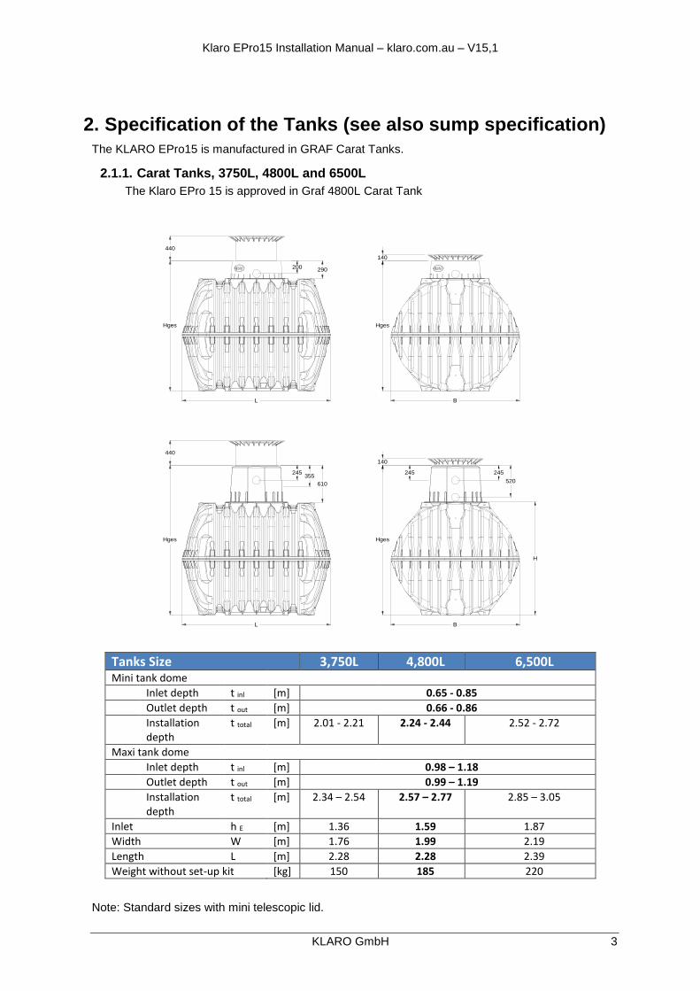
The KLARO EPro15 is manufactured in GRAF Carat Tanks.
2.1.1. Carat Tanks, 3750L, 4800L and 6500L
The Klaro EPro 15 is approved in Graf 4800L Carat Tank
Note: Standard sizes with mini telescopic lid.
Tanks Size 3,750L 4,800L 6,500L Mini tank dome
Inlet depth t inl [m] 0.65 - 0.85
Outlet depth t out [m] 0.66 - 0.86
Installation depth
t total [m] 2.01 - 2.21 2.24 - 2.44 2.52 - 2.72
Maxi tank dome
Inlet depth t inl [m] 0.98 – 1.18
Outlet depth t out [m] 0.99 – 1.19
Installation depth
t total [m] 2.34 – 2.54 2.57 – 2.77 2.85 – 3.05
Inlet h E [m] 1.36 1.59 1.87
Width W [m] 1.76 1.99 2.19
Length L [m] 2.28 2.28 2.39
Weight without set-up kit [kg] 150 185 220
Hges
245
440
L
355
610
140
Hges
245
520
245
B
H
Hges
200
440
L
290
B
140
Hges
KLARO Installation Manual V15.1
4
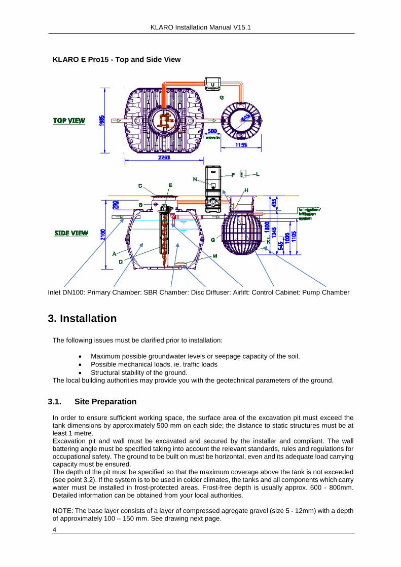
KLARO E Pro15 - Top and Side View
Inlet DN100: Primary Chamber: SBR Chamber: Disc Diffuser: Airlift: Control Cabinet: Pump Chamber
3. Installation
The following issues must be clarified prior to installation:
Maximum possible groundwater levels or seepage capacity of the soil.
Possible mechanical loads, ie. traffic loads
Structural stability of the ground. The local building authorities may provide you with the geotechnical parameters of the ground.
3.1. Site Preparation In order to ensure sufficient working space, the surface area of the excavation pit must exceed the tank dimensions by approximately 500 mm on each side; the distance to static structures must be at least 1 metre. Excavation pit and wall must be excavated and secured by the installer and compliant. The wall battering angle must be specified taking into account the relevant standards, rules and regulations for occupational safety. The ground to be built on must be horizontal, even and its adequate load carrying capacity must be ensured. The depth of the pit must be specified so that the maximum coverage above the tank is not exceeded (see point 3.2). If the system is to be used in colder climates, the tanks and all components which carry water must be installed in frost-protected areas. Frost-free depth is usually approx. 600 - 800mm. Detailed information can be obtained from your local authorities. NOTE: The base layer consists of a layer of compressed agregate gravel (size 5 - 12mm) with a depth of approximately 100 – 150 mm. See drawing next page.
Red Hose Feeding air-lifter
Blue Hose diffuser air feed
Empty DN100 Connected to tank dome
White Hose Sludge Return

Klaro EPro15 Installation Manual – klaro.com.au – V15,1
KLARO GmbH 5
Installation Diagram
3.2. Installation requirements General information:
Special installation provisions must be observed for groundwater and slopes. Standard models can be walked on. In approved trafficable areas, tanks with a volume of more than 3,750 l can be driven over with trucks of up to 12 tons if the covering is reinforced as specified in point.
Requirements include: o Installation only in accessible areas. o The tank must not be installed in groundwater and artesian water.
3.2.1. Groundwater and cohesive (water-impermeable) ground
In cases where only occasional groundwater, cohesive and water-impermeable ground (e.g. clay) occurs, appropriate drainage for groundwater and seepage water must be provided to ensure that the maximum water level of the tank in the groundwater never exceeds the values indicated in the table. If necessary, the drainage pipe must end in a vertically installed DN 300 pipe with inserted submersion pressure pump which pumps out the excess water. The pump must be checked on a regular basis. If the tanks are expected to immerse deeper, it is absolutely necessary to provide adequate drainage.
Tank Size [l] 3,750L 4,800L 6,500L Max. immersion depth [m] 1.59 0.91 1.05
Min. soil cover [m] 0.80 0.80 0.80
1. Soil
2. Dome shaft with telescopic Lid.
3. Compressed substructure
4. Shell (round grain gravel, max.
grain size 12mm.
5. Cover layer
6. Wastewater Treatment Tank
7. Concrete layer for areas driven on
with cars

KLARO Installation Manual V15.1
6
3.2.2 Slope or embankment.
If the tank is to be installed in the direct vicinity (< 5 m) of a slope, mound of earth or embankment, a statically calculated supporting wall which supports earth pressure must be constructed. The wall must protrude beyond the tank dimensions by at least 500mm in all directions with a minimum distance of 1 metre to the tank.
3.2.3 Installation in trafficable areas.
Coverage heights for cast iron telescopic dome Lid (class B) in areas which are trafficable by cars (load up to 3.5 t)
(without groundwater or artesian water).
4. Installation of the tanks
4.1 Re-check Prior to the installation of the tanks, the installation depth must be re-checked, with regard to inlet and outlet height. Tanks must be placed and aligned in compliance with the applicable installation drawing. Special attention must be paid to the exact horizontal installation of the tank.
4.2 Backfilling Tanks must be lowered into the prepared excavation pit using appropriate lifting lugs (see point 2.1 and 2.3 - Transport and Storage). Impacts on the sides of the pit must be avoided. In order to avoid deformation, tanks must be filled with water (1/3) prior to back filling around the tank. Backfill around the tanks (agregate gravel with a maximum size of 12mm.) layer by layer in steps of a maximum of 300mm for Single Tanks Systems and 400mm for Multi Carat tank systems. Each layer must be well compressed (hand tamper). Make sure not to damage the tanks when compressing the back fill. NOTE: Never use mechanical compression machines.
Klaro EPro15 Installation Manual – klaro.com.au – V15,1
KLARO GmbH 7
The backfill must have a width of minimum 500mm. The pit must be quickly filled in with aggregate gravel within one day. Otherwise, in the event of heavy rain, there is a risk of excessive loads due to backwater. Filling material:
– The filling material must be compactable, permeable, shear resistant, frost-proof and free from sharp objects.
– These requirements are for example met by aggregate gravel (with max. size 12mm.)
– Excavated soil or sand is not suitable in most cases.
– Topsoil, clay and other cohesive soil is not suitable as filling material.
5. Technical assembly
5.1. Connection of piping
5.1.1. Inlet & Outlet
Inlet and outlet pipes (DWV 100) must be connected according to the drawing. All inlet and outlet pipes must be laid with an incline of at least 1% (subsequent laying of pipes must be taken into account). The pipes are connected to the pre-drilled holes at the dome shaft or at the tanks.
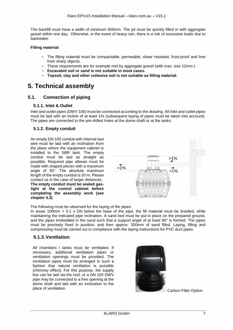
5.1.2. Empty conduit
An empty DN 100 conduit with internal taut wire must be laid with an inclination from the place where the equipment cabinet is installed to the SBR tank. The empty conduit must be laid as straight as possible. Required pipe elbows must be made with shaped pieces with a maximum angle of 30°. The absolute maximum length of the empty conduit is 20 m. Please contact us in the case of larger distances. The empty conduit must be sealed gas-tight at the control cabinet before completing the assembly work (see chapter 4.3) The following must be observed for the laying of the pipes: In areas 100mm + 0.1 x DN below the base of the pipe, the fill material must be levelled, while maintaining the indicated pipe inclination. A sand bed must be put in place on the prepared ground, and the pipes embedded in the sand such that a support angle of at least 90° is formed. The pipes must be precisely fixed in position, and then approx. 300mm of sand filled. Laying, filling and compressing must be carried out in compliance with the laying instructions for PVC duct pipes.
5.1.3. Ventilation
All chambers / tanks must be ventilated. If necessary, additional ventilation pipes or ventilation openings must be provided. The ventilation pipes must be arranged in such a fashion that natural ventilation is possible (chimney effect). For this purpose, the supply line can be laid via the roof, or a DN 100 DWV pipe may be connected to a free opening at the dome shaft and laid with an inclination to the place of ventilation.
Carbon Filter Option
>1%
>1%>1%
KLARO Installation Manual V15.1
8
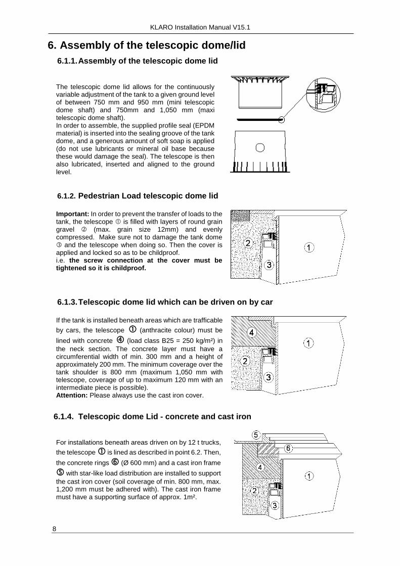
6. Assembly of the telescopic dome/lid
6.1.1. Assembly of the telescopic dome lid
The telescopic dome lid allows for the continuously variable adjustment of the tank to a given ground level of between 750 mm and 950 mm (mini telescopic dome shaft) and 750mm and 1,050 mm (maxi telescopic dome shaft). In order to assemble, the supplied profile seal (EPDM material) is inserted into the sealing groove of the tank dome, and a generous amount of soft soap is applied (do not use lubricants or mineral oil base because these would damage the seal). The telescope is then also lubricated, inserted and aligned to the ground level.
6.1.2. Pedestrian Load telescopic dome lid
Important: In order to prevent the transfer of loads to the tank, the telescope is filled with layers of round grain gravel (max. grain size 12mm) and evenly compressed. Make sure not to damage the tank dome and the telescope when doing so. Then the cover is applied and locked so as to be childproof. i.e. the screw connection at the cover must be tightened so it is childproof.
6.1.3. Telescopic dome lid which can be driven on by car
If the tank is installed beneath areas which are trafficable
by cars, the telescope (anthracite colour) must be
lined with concrete (load class B25 = 250 kg/m²) in
the neck section. The concrete layer must have a circumferential width of min. 300 mm and a height of approximately 200 mm. The minimum coverage over the tank shoulder is 800 mm (maximum 1,050 mm with telescope, coverage of up to maximum 120 mm with an intermediate piece is possible). Attention: Please always use the cast iron cover.
6.1.4. Telescopic dome Lid - concrete and cast iron
For installations beneath areas driven on by 12 t trucks,
the telescope is lined as described in point 6.2. Then,
the concrete rings (Ø 600 mm) and a cast iron frame
with star-like load distribution are installed to support
the cast iron cover (soil coverage of min. 800 mm, max. 1,200 mm must be adhered with). The cast iron frame must have a supporting surface of approx. 1m².

Klaro EPro15 Installation Manual – klaro.com.au – V15,1
KLARO GmbH 9
6.1.5. Assembly of the extension riser
Extension riser pieces which are required for major soil covers must be inserted into the tank dome using soft soap. The profile seal must be inserted into the top groove of the intermediate piece and well lubricated. Then the telescopic dome shaft must be inserted and adjusted to the planned ground surface of the surrounding area. 1 exension piece = max. soil coverage of 1,200 mm (each in connection with the maxi telescopic dome shaft) Telescopic dome Lid (can be tilted by 5°) Extension Riser Tank dome (can be rotated by 360°)
7. Filling with water
After connecting the air hoses, the tanks must be filled with fresh water as the backfilled in accordance with the diagram below
7.1.
1. 1/3
2. 3/3

KLARO Installation Manual V15.1
10
8. Air hoses
Four air hoses are required for the connection between the SBR container and control cabinet. In order to avoid mixing up of the hoses when connecting, they are supplied in different colours – corresponding to the coloured coding of the lifter in the tank.
Valve Colour Part Internal diameter of the hose
1 Black Outlet lifter 13 mm (19 mm from 40 EP)
2 Blue Ventilation 19 mm
3 White Excess sludge lifter 13 mm (19 mm from 40 EP)
4 Red Charging lifter 13 mm (19 mm from 40 EP)
The distance between tanks and control cabinet should not exceed 20m. Please contact us in the case of larger distances. A bag with hose clips is present at the riser of the ventilation system. They must be used to connect the continuing air hoses to the corresponding tails of the pre-mounted hoses at the access opening of the SBR tank. The red hose which is pre-mounted to the charging lifter must be laid through the return pipe from the sludge reservoir to the access opening of the SBR reactor. Finally, the four air hoses must be drawn through the empty conduit using a taut wire. Please make sure not to bend the air hoses.
( Empty tube DN 100)
Charging air-lifter
Pipe lead red hose
Extra-sludge air-lifter
Membrane disc Discharging air-lifter
(Membrane disc)
(Discharging air-lifter)
(Extra-sludge air-lifter)
(Charging air-lifter)
Inlet DN 100
Outlet DN 100
Red hose
White hose
Blue hose
Black hose
Connected to manhole
Klaro EPro15 Installation Manual – klaro.com.au – V15,1
Graf Australia Pty Ltd - KLARO Wastewater Systems 11
9. Installation & Assembly of the control cabinet
9.1. Installation in external locations
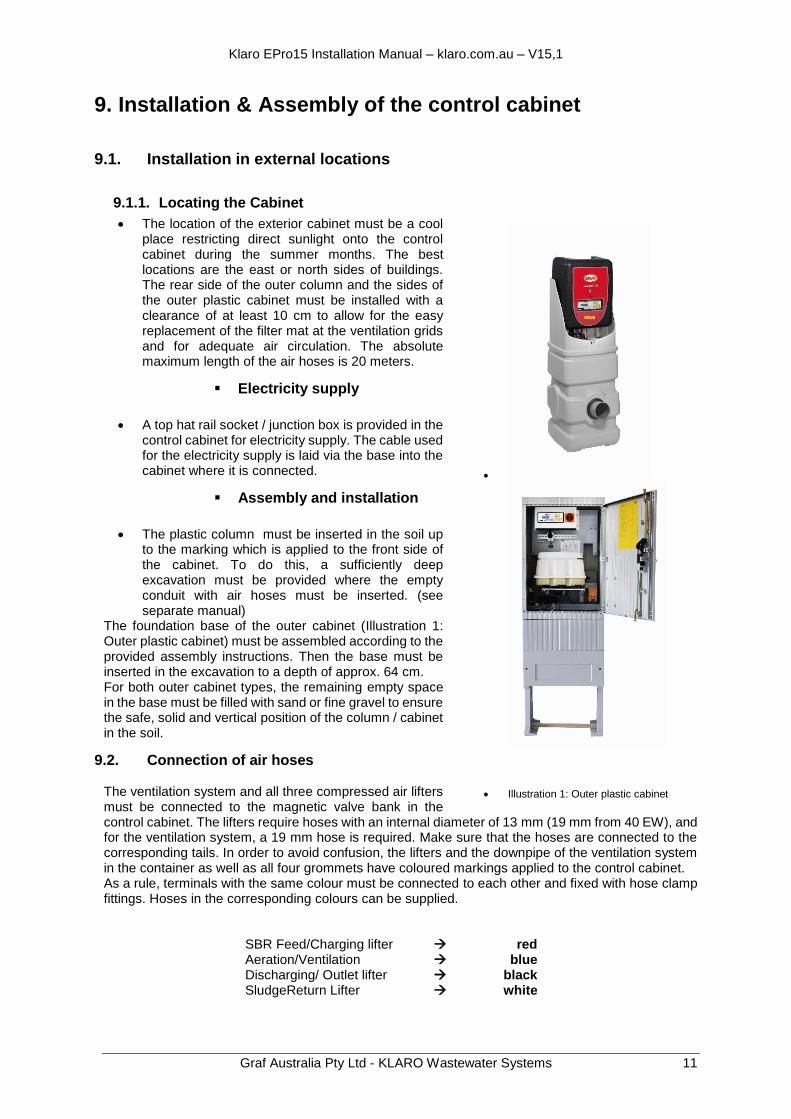
9.1.1. Locating the Cabinet
The location of the exterior cabinet must be a cool place restricting direct sunlight onto the control cabinet during the summer months. The best locations are the east or north sides of buildings. The rear side of the outer column and the sides of the outer plastic cabinet must be installed with a clearance of at least 10 cm to allow for the easy replacement of the filter mat at the ventilation grids and for adequate air circulation. The absolute maximum length of the air hoses is 20 meters.
Electricity supply
A top hat rail socket / junction box is provided in the control cabinet for electricity supply. The cable used for the electricity supply is laid via the base into the cabinet where it is connected.
Assembly and installation
The plastic column must be inserted in the soil up to the marking which is applied to the front side of the cabinet. To do this, a sufficiently deep excavation must be provided where the empty conduit with air hoses must be inserted. (see separate manual)
The foundation base of the outer cabinet (Illustration 1: Outer plastic cabinet) must be assembled according to the provided assembly instructions. Then the base must be inserted in the excavation to a depth of approx. 64 cm. For both outer cabinet types, the remaining empty space in the base must be filled with sand or fine gravel to ensure the safe, solid and vertical position of the column / cabinet in the soil.
9.2. Connection of air hoses
The ventilation system and all three compressed air lifters must be connected to the magnetic valve bank in the control cabinet. The lifters require hoses with an internal diameter of 13 mm (19 mm from 40 EW), and for the ventilation system, a 19 mm hose is required. Make sure that the hoses are connected to the corresponding tails. In order to avoid confusion, the lifters and the downpipe of the ventilation system in the container as well as all four grommets have coloured markings applied to the control cabinet. As a rule, terminals with the same colour must be connected to each other and fixed with hose clamp fittings. Hoses in the corresponding colours can be supplied. SBR Feed/Charging lifter red Aeration/Ventilation blue Discharging/ Outlet lifter black SludgeReturn Lifter white
Illustration 1: Outer plastic cabinet
KLARO Installation Manual V15.1
12
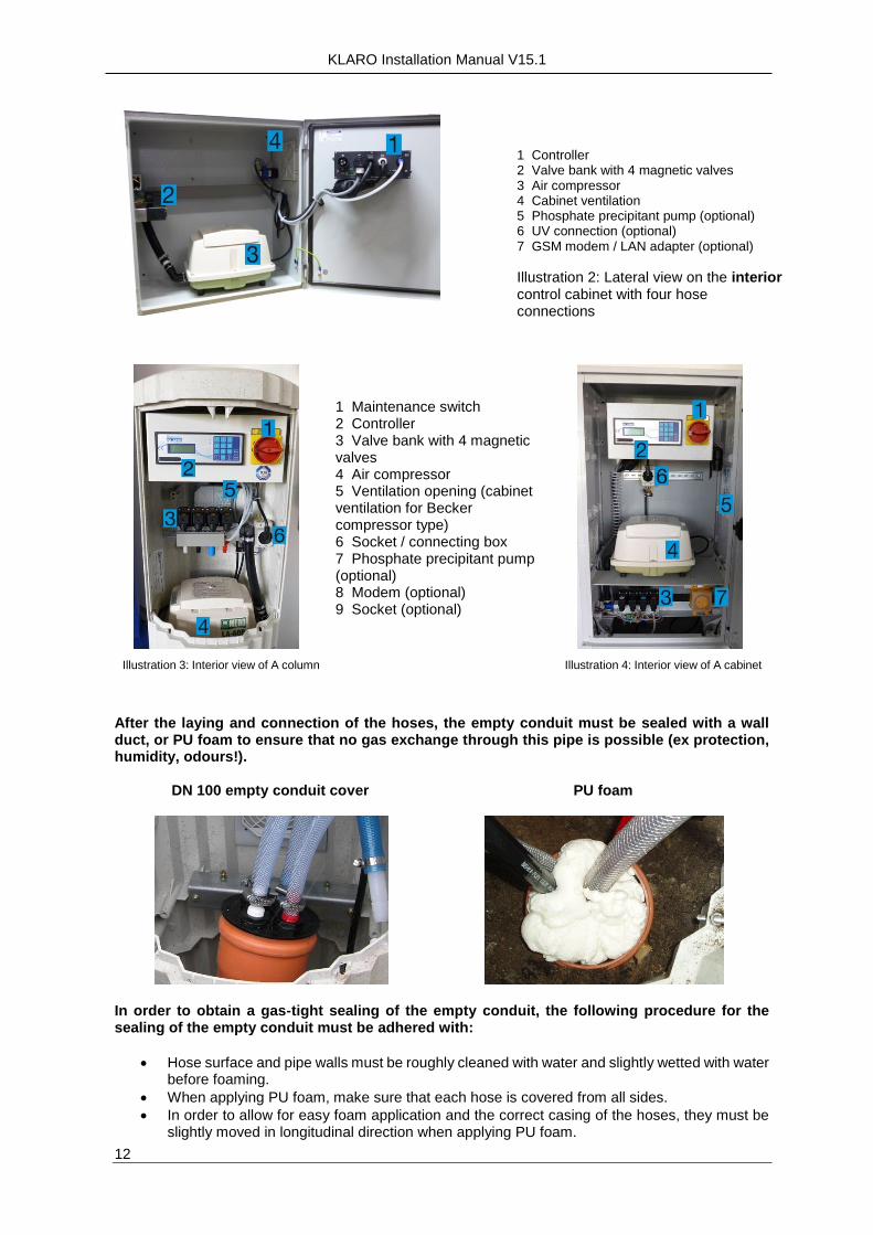
1 Controller 2 Valve bank with 4 magnetic valves 3 Air compressor 4 Cabinet ventilation 5 Phosphate precipitant pump (optional) 6 UV connection (optional) 7 GSM modem / LAN adapter (optional)
Illustration 2: Lateral view on the interior control cabinet with four hose connections
Illustration 3: Interior view of A column
1 Maintenance switch 2 Controller 3 Valve bank with 4 magnetic valves 4 Air compressor 5 Ventilation opening (cabinet ventilation for Becker compressor type) 6 Socket / connecting box 7 Phosphate precipitant pump (optional) 8 Modem (optional) 9 Socket (optional)
Illustration 4: Interior view of A cabinet
After the laying and connection of the hoses, the empty conduit must be sealed with a wall duct, or PU foam to ensure that no gas exchange through this pipe is possible (ex protection, humidity, odours!).
DN 100 empty conduit cover
PU foam
In order to obtain a gas-tight sealing of the empty conduit, the following procedure for the sealing of the empty conduit must be adhered with:
Hose surface and pipe walls must be roughly cleaned with water and slightly wetted with water before foaming.
When applying PU foam, make sure that each hose is covered from all sides.
In order to allow for easy foam application and the correct casing of the hoses, they must be slightly moved in longitudinal direction when applying PU foam.
Klaro EPro15 Installation Manual – klaro.com.au – V15,1
Graf Australia Pty Ltd - KLARO Wastewater Systems 13
10. Commissioning
The Commissioning Report for the Klaro SBR Wastewater System and the description in the Operating Manual must be adhered with when commissioning. These documents are supplied with your system or available from Graf Australia at [email protected] if required.
Important Commissioning Checklist
– Ground or surface water drains away from the System
– The plant is filled with fresh water
– There is no damage to the tanks, components, air lift or interconnecting piping
The maintenance switch must be turned to "I".
The series number and version number of the program are displayed on the control for a few seconds before it switches to automatic mode.
The warning message "Set date and time!" occurs. This message can be acknowledged by pressing the ESC key twice. If a second warning message "Temp. max" appears, you must check whether the temperature sensor at the rear side of the device is correctly plugged in.
The current operating mode of the system is then displayed on the liquid crystal display. For the correct storage of operating hours and event messages, date and time must be set with the appropriate menu item.
The system initially runs in the “cycle break” until the first cycle starting time have been reached.
These are the cycle starting times preset in the factory: o 1:30 am; 7:30 am; 1:30 pm; 7:30 pm
The correct function of the aeration system as well as the lifter must be checked in manual mode. The appropriate procedure is described in detail in the System Manual which is available in the Control Cabinet. Bubble formation during ventilation must be even and complete. The compressed air lifters only work if tanksr are adequately filled with water.
11. Return of the commissioning report
The commissioning report must be completely filled in.
- The original copy of the commissioning report must be archived in the files of the operator.
- The first copy must be returned to the following address:
GRAF AUSTRALIA PTY LTD: 2, 8 Piper Street CABOOLTURE QLD 4510
- The second copy is for the company installing the system. Attention: Warranty claims can only be processed if the commissioning report has been supplied to Graf Australia Pty Ltd
GRAF AUSTRALIA PTY LTD Klaro Wastewater Systems
2, 8 Piper Street, CABOOLTURE Q 4510
Phone: 1300 466 469 [email protected]
www.klaro.au