kippzonen manual pyranometer cm4 v1007
DESCRIPTION
MANUAL PIRANOMETRUTRANSCRIPT
Instruction Manual
High Temperature PyranometerCM 4
1
IMPORTANT USER INFORMATION
Reading this entire manual is recommended for full understanding of the use of this product.
The exclamation mark within an equilateral triangle is intended to alert the user to the presence of important operating and maintenance instructions in the literature accompanying the instrument. Should you have any comments on this manual we will be pleased to receive them at: Kipp & Zonen B.V. Delftechpark 36 2628 XH Delft Holland P.O. Box 507 2600 AM Delft Holland Phone +31 (0)15 2755210 Fax +31 (0)15 2620351 Email [email protected] Web www.kippzonen.com Kipp & Zonen reserve the right to make changes to the specifications without prior notice.
WARRANTY AND LIABILITY
Kipp & Zonen guarantees that the product delivered has been thoroughly tested to ensure that it meets its published specifications. The warranty included in the conditions of delivery is valid only if the product has been installed and used according to the instructions supplied by Kipp & Zonen. Kipp & Zonen shall in no event be liable for incidental or consequential damages, including without limitation, lost profits, loss of income, loss of business opportunities, loss of use and other related exposures, however caused, arising from the faulty and incorrect use of the product. User made modifications can affect the validity of the CE declaration.

2
COPYRIGHT© 2010 KIPP & ZONEN
All rights reserved. No part of this publication may be reproduced, stored in a retrieval system or transmitted in any form or by any means, without permission in written form from the company. Manual version 1007
3
CALIBRATION CERTIFICATE
The calibration certificate supplied with the instrument is valid from the date of first use. Even though the calibration certificate is dated relative to manufacture the instrument does not undergo any sensitivity changes when kept in the original packing. From the moment the instrument is taken from it’s packaging and exposed to irradiance the sensitivity will deviate with time. See also the 'non-stability' performance (max. sensitivity change / year) given in the radiometer specification list.

4
DECLARATION OF CONFORMITY
According to EC guideline 89/336/EEC We Kipp & Zonen B.V. Delftechpark 36 2628 XH Delft The Netherlands Declare under our sole responsibility that the product Type: CM 4 Name: High Temperature Pyranometer To which this declaration relates is in conformity with the following standards Imissions EN 50082-1 Group standard
Emissions EN 50081-1 Group standard EN 55022 Following the provisions of the directive
B.A.H. Dieterink
President KIPP & ZONEN B.V.

5

6

7
TABLE OF CONTENTS
IMPORTANT USER INFORMATION..............................................1
CALIBRATION CERTIFICATE .......................................................2
DECLARATION OF CONFORMITY ...............................................4
1 GENERAL INFORMATION........................................................9 1.1 INTRODUCTION ...................................................................9 1.2 PHYSICAL PRINCIPLES OF THE PYRANOMETER ....................10 1.2.1 Temperature Dependency ...........................................11 1.2.2 Spectral properties of the glass dome .........................13 1.2.3 Directional / Cosine response......................................14 1.2.4 Non-linearity.................................................................15 2 LIST OF SPECIFICATIONS.....................................................17
3 INSTALLATION .......................................................................21 3.1 DELIVERY.........................................................................21 3.2 MECHANICAL INSTALLATION ..............................................21 3.2.1 Outdoor installation......................................................22 3.2.2 Indoor installation.........................................................22 3.3 ELECTRICAL CONNECTION .................................................23 4 OPERATION ........................................................................27
5 MAINTENANCE .......................................................................29
6 CALIBRATION ........................................................................31 6.1 INITIAL CALIBRATION..........................................................31 6.2 RECALIBRATION................................................................31 6.3 CALIBRATION PROCEDURE AT KIPP & ZONEN .....................33 6.3.1 The facility....................................................................33 6.3.2 Procedure ....................................................................33 6.3.3 Calculation ...................................................................34 6.3.4 Zero offset....................................................................34

8
6.3.5 Traceability to World Radiometric Reference ..............35 7 FREQUENTLY ASKED QUESTIONS (FAQ’S).......................37
8 TROUBLE SHOOTING ............................................................39
9 PART NUMBERS / SPARE PARTS / OPTIONS.....................41
APPENDIX I PYRANOMETER CLASSIFICATION ACCORDING TO WMO GUIDE 1996 ............43
APPENDIX II PT-100 SPECIFICATIONS.............................45
APPENDIX III LIST OF WORLD AND REGIONAL RADIATION CENTRES..................................47
APPENDIX IV RECALIBRATION SERVICE .........................49

9
1 GENERAL INFORMATION 1.1 INTRODUCTION The CM 4 High Temperature Pyranometer is an instrument for measuring solar or artificial light irradiance. The instrument is specially designed for usage under extreme irradiance and temperature conditions. With an operating temperature range of -40°C to +150°C and measurement up to 4000 W/m² it is a unique product. All the radiometer components, including the signal cable, are specially selected for their ability to withstand these extremely high temperatures and irradiances. In particular the CM4 has been developed for applications in an industrial environment. The pyranometer is designed for both continuous indoor and outdoor use. Because of the fact that it has a flat spectral sensitivity from roughly 0.3 to 3 microns, its calibration is valid for natural sunlight and for most types of artificial light (e.g. Xenon lamps, halogen lamps). CM 4 features:
• Robust and high temperature resistant construction and cable
• Unique temperature compensation of sensor sensitivity • Low non-linearity • Exchangeable with meteorological field pyranometers • Easy maintenance with easily accessible drying cartridge • Built-in Pt-100 4-wire temperature sensor
1. GENERAL INFORMATION
10
The CM 4 Pyranometer complies with specifications according to the ISO 9060 standard, as defined in the ‘Guide to meteorological Instruments and Methods of Observation’, sixth edition, 1996, of the World Meteorological Organisation (WMO*) – Geneva – Switzerland. * The WMO classification is adapted from the international standard ISO 9060 (1990).
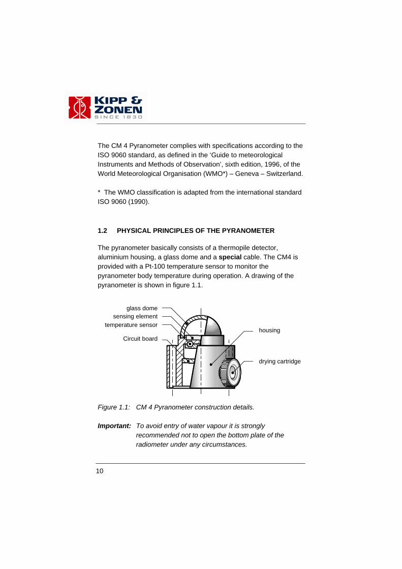
1.2 PHYSICAL PRINCIPLES OF THE PYRANOMETER The pyranometer basically consists of a thermopile detector, aluminium housing, a glass dome and a special cable. The CM4 is provided with a Pt-100 temperature sensor to monitor the pyranometer body temperature during operation. A drawing of the pyranometer is shown in figure 1.1.
Figure 1.1: CM 4 Pyranometer construction details. Important: To avoid entry of water vapour it is strongly
recommended not to open the bottom plate of the radiometer under any circumstances.
sensing element
housingtemperature sensor
drying cartridge
glass dome
Circuit board
11
The thermopile surface is coated with black absorbent paint. Absorbed radiation is converted into heat which flows through the thermal resistance of the thermopile to the heat-sink. The temperature difference (ΔT) across the thermal resistance of the detector is converted into a voltage. Most electrical and physical specifications are determined by the thermopile. The thermopile and the dome determine the spectral specifications. The optimal geometry of both the glass dome and the thermopile enables the pyranometer to have a 180° field of view with good cosine response.
1.2.1 Temperature Dependency One of the physical principles of a pyranometer is that at a constant irradiance the detector sensitivity changes with the instrument temperature. ISO 9060 defines this temperature response as the percentage deviation due to a change in the ambient temperature within a specific range of 50 K. The CM 4 temperature dependency however is specified within an range of 170 K. To keep the pyranometer performance acceptable the instrument output signal is electrically compensated. Due to the perfectly balanced thermoelectric construction the CM 4 temperature dependence is kept within a deviation of 3%, within the range of -20 °C to 0 °C, 2% within the range of 0 °C to +100 °C and 3% within the range of +100 °C to +150 °C . After manufacturing, each instrument is individually checked for its temperature dependency performance. This is measured in 8 steps of 25 °C from -25 °C to +150 °C. A typical temperature response of an electrically compensated CM 4 is given in figure 1.2.
1. GENERAL INFORMATION

12
Temperature dependency of the sensitivity
-3.000
-2.000
-1.000
0.000
1.000
2.000
3.000
-40 -20 0 20 40 60 80 100 120 140 160
Instrument temperature (°C)
Tem
pera
ture
dep
ende
ncy
[%]
Figure 1.2: Typical temperature dependency curve of the CM 4. The CM 4 High Temperature Pyranometer is supplied with its own individual graph of temperature dependence of sensitivity. Monitoring the temperature during operation will allow easy data correction afterwards for improved measurement accuracy. The table in Appendix II lists how to interpret the Pt-100 output readings. To guarantee long-term stability the CM 4 circuitry consists of high temperature resistant components, such that continuous high irradiance measurements have a minimum effect on the durability or the stability of the instrument.

13
1.2.2 Spectral properties of the glass dome The spectral properties of a pyranometer are determined by the properties of the black absorbent paint and the glass dome. The spectral response is given in figure 1.3. Figure 1.3: The spectral transmission of the glass dome pyranometer
combined with the spectrum of the sun under a clear sky.
1. GENERAL INFORMATION
14
1.2.3 Directional / Cosine response The measurement of the radiation falling on a plane surface (also called irradiance or radiative flux) requires two assumptions: that the surface is spectrally black (that it absorbs all radiation of all wavelengths) and that it has a 180° field of view. Another way of expressing these directional properties is to say that the sensor has to comply with an ideal cosine response. ISO 9060 defines the cosine response (or directional response) as the range of errors caused by assuming that the normal incidence responsitivity is valid for all directions when measuring with a beam radiation whose normal angle of incidence irradiance is 1000 W/m². A perfect cosine response will show maximum sensitivity (1) at an angle of incidence of 0° (perpendicular to the sensor surface) and zero sensitivity at an angle of incidence of 90° (radiation passing over the sensor surface). In between 0 and 90 degrees the sensitivity should be proportional the cosine of the angle of incidence. Figure 1.4 shows the typical curve and the maximum percentage deviation of a CM 4 pyranometer. The vertical axis shows the deviation from ideal behaviour, expressed in percents of the ideal value.

15
-6
-4
-2
0
2
4
6
8
10
0 10 20 30 40 50 60 70 80
min. cosine error %typical cosine error %max. cosine error %
degrees
[%]
Figure 1.4: The mean cosine response of the pyranometer. With the angle
of incidence on the horizontal axis and the percentage deviation from ideal cosine behaviour on the vertical axis.
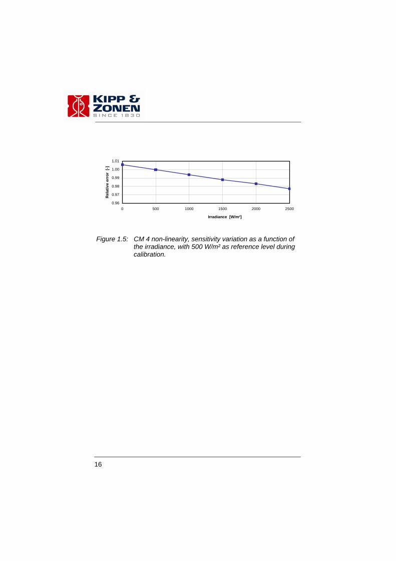
1.2.4 Non-linearity Non-linearity is the error of the sensitivity variation as a function of the variation in irradiance. ISO 9060 defines non-linearity of an instrument as its percentage deviation from the responsitivity at 500 W/m² due to the change in irradiance within 100 W/m² to 1000 W/m². The linearity however is strongly related to the pyranometer design and body. Due to a thermal gradient over the hot and cold junctions (by absorption of radiation) heat convection at the detector surface causes a non-linearity effect. The CM 4 detector construction has been designed to keep the thermal gradient very low. Even when the pyranometer is exposed to a very intense artificial radiating source the non-linearity of the sensor sensitivity is small. The CM 4 non-linearity is show in figure 1.5.
1. GENERAL INFORMATION
16
0.96
0.97
0.98
0.99
1.00
1.01
0 500 1000 1500 2000 2500
Irradiance [W/m²]
Rel
ativ
e er
ror
[-]
Figure 1.5: CM 4 non-linearity, sensitivity variation as a function of
the irradiance, with 500 W/m² as reference level during calibration.

17
2 LIST OF SPECIFICATIONS
Spectral range: 300 to 2800 nm, 50% points Sensitivity: 7 µV/Wm-2 (nominal) Impedance: 500 to 2000 Ω Response time: 18 s (95% response) < 8 s (63% response) Non-linearity: Max. 3 % (0 - 2500 W/m2) Directional error (at 80° with a 1000 W/m² beam): ± 20 W/m² Temperature dependence of sensitivity: 3 % (-20 °C to +0 °C) 2 % (0 °C to +100 °C) 3 % (+100 °C to +150 °C) Tilt error: Max. 1% deviation when facing downwards Zero-offset due to temperature changes: Max. 4 W/m2 offset for 5 K/h temp.
change. Zero-offset due to FIR (200 W/m2): ± 15 W/m2 Operating temperature: -40 °C to +150 °C Field of view: 180° (2 π sr) Max irradiance: 4000 W/m2 Non-stability: ± 1% sensitivity change per year
SPECIFICATIONS
18
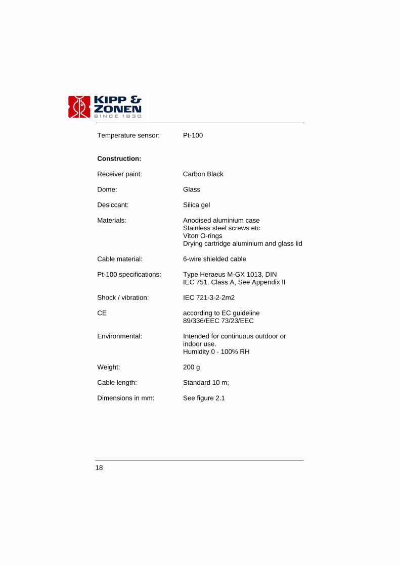
Temperature sensor: Pt-100 Construction: Receiver paint: Carbon Black Dome: Glass Desiccant: Silica gel Materials: Anodised aluminium case Stainless steel screws etc Viton O-rings Drying cartridge aluminium and glass lid Cable material: 6-wire shielded cable Pt-100 specifications: Type Heraeus M-GX 1013, DIN IEC 751. Class A, See Appendix II Shock / vibration: IEC 721-3-2-2m2 CE according to EC guideline 89/336/EEC 73/23/EEC Environmental: Intended for continuous outdoor or
indoor use. Humidity 0 - 100% RH Weight: 200 g Cable length: Standard 10 m; Dimensions in mm: See figure 2.1

19
Figure 2.1: CM 4 Dimensions.
SPECIFICATIONS

20

21
3 INSTALLATION Reading the installation instruction before installation is recommended for full understanding of the use of this product. 3.1 DELIVERY Check the contents of the shipment for completeness (see below) and note whether any damage has occurred during transport. If there is damage, a claim should be filed with the carrier immediately. In this case, and also if the contents are incomplete, your dealer should be notified in order to facilitate the repair or replacement of the instrument. The CM 4 pyranometer delivery will include the following items: 1. CM 4 pyranometer 2. Calibration certificate 3. Manual 4. Temperature dependency data 5. 2 x desiccant packs Unpacking Keep the original packaging for later shipments! Although all sensors are weatherproof and suitable for rough ambient conditions, they do partially consist of delicate mechanical parts. For this type of equipment, keep the original shipment packaging to safely transport the equipment to the measurement site. 3.2 MECHANICAL INSTALLATION The mechanical installation of the pyranometer depends upon the measurement purpose. Different measurement methods are explained in the next sections.
3. INSTALLATION
22
3.2.1 Outdoor installation When installed permanently, the pyranometer can be attached to its mounting platform by means of the holes that are drilled through the body, see figure 2.1. Preferred orientation is with the cable pointing to the nearest pole. When installed on a mast, preferred orientation is such that no shadow is cast on the pyranometer during any time of the day. In the Northern hemisphere this implies that the pyranometer should be south of the mast. The pyranometer can be used to measure reflected radiation, for instance when pointed towards the earth in the inverted position. When measuring reflected radiation (as an albedometer) it is advised to do this at a height of at least 1.5 meters above the surface, to avoid shading effects and to promote spatial averaging.
3.2.2 Indoor installation When continuously used for indoor purposes the instrument should preferably be attached to a mounting platform by means of the holes that are drilled through the body, see figure 2.1. However, this might not always be possible, for instance if the instrument is relocated or moved regularly. What is recommended in these cases is to relocate the instrument in the same place as much as possible, attempting to repeat the same measurement conditions e.g. with respect to a fixed offset from a light reflecting wall or any other object. In the case of measuring the light irradiance on tilted surfaces it is recommended to tilt and fix the radiometer at the same inclination as the surface.

23
3.3 ELECTRICAL CONNECTION The CM 4 is provided with a special 10 m cable with six leads and a shield covered with a black sleeve. The colour code is: red = plus blue = minus Shield = case Pt-100 temperature sensor (4 – wire connection)
White: Pt 100 (combined with black) Black: Pt 100 (combined with white Green: Pt 100 (combined with yellow) Yellow: Pt 100 (combined with green)
The shield is directly connected to the case. Preferably the shield should be connected to the same ground at the readout equipment, to reduce cable noise. The cable must be firmly secured to minimise spurious response during any mechanical movement or vibration (pressing the cable produces voltage spikes, a tribo-electric effect and capacitance effect). Looking at the circuit diagram of figure 3.1, it is clear that the impedance of the readout equipment is loading the thermistor circuit and the thermopile. This can increase the temperature dependency of the pyranometer. The sensitivity is affected more than 0.1% when the load resistance is less than 1.5 MΩ. For this reason we recommend the use of readout equipment with an input impedance of 1.5 MΩ or more, such as potentiometric recorders, digital voltmeters, etc. The solar integrators and chart recorders available from Kipp & Zonen meet these requirements. Extension cables may be used, but the cable resistance must be smaller than 0.1% of the impedance of the readout equipment.
3. INSTALLATION

24
Figure 3.1: Circuit diagram of the CM 4 Pyranometer and connection to
readout equipment. It is evident that application of attenuator circuits to the CM 4 output in order to modify the calibration factor is not recommended because the temperature response will also be affected. However, recorders with a variable voltage range can be set so that the result can be read out directly in W/m2. A considerable input bias current in the readout equipment can produce a voltage of several micro-volts across the impedance of the pyranometer. The correct measured zero signal can be verified with a resistance replacing the pyranometer impedance at the input terminals. With the availability of a low voltage analogue input module with A/D converter the pyranometer can be connected to a computer or data acquisition system. The span and resolution of the A/D converter in the module must allow a system sensitivity of about 1 bit per W/m2.

25
For amplification of the pyranometer signal Kipp & Zonen recommends the 4-20 mA Signal Amplifier, available from Kipp & Zonen. This amplifier converts the micro-Volt output from the pyranometer into a standard 4–20 mA signal. Zero and Span adjustment of the pyranometer signal are provided.
3. INSTALLATION

26

27
4 OPERATION After completing the installation the pyranometer will be ready for operation. The irradiance value (E) can be simply computed by dividing the output signal (Uemf) of the pyranometer by its sensitivity (Sensitivity) as shown in formula 1, or by multiplication of the voltage value with the reciprocal of the sensitivity, often called the calibration factor. The CM 4 pyranometer sensitivity is given in the supplied calibration certificate. For calculation of the solar irradiance the following formula must be applied:
ensitivity
emf
SUE = (Formula 1)
E = Global radiation [W/m2] Uemf = Output of pyranometer [μV] Sensitivity = Sensitivity of pyranometer [μV/W/m2]
4. OPERATION

28

29
5 MAINTENANCE Once installed the pyranometer needs little maintenance. The pyranometer dome must be kept clean and inspected regularly. Ensure that the silica gel is still coloured orange. When the orange silica gel in the drying cartridge is turned completely transparent (normally after several months), it must be replaced by active silicagel as supplied in the small refill packs. The content of one pack is sufficient for one complete refill.
In humid areas it is usual to replace the desiccant twice a year. The replacement interval is affected by humidity, variations in air pressure and the extent of temperature changes. Some tips when changing the desiccant: - Do not remove the desiccant cartridge unnecessarily. - Dirt in combination with water is the main cause of corrosion.
Make sure the surfaces of the pyranometer and the cartridge that touch the rubber sealing ring are clean.
- For a better seal, the rubber ring is normally coated with silicon grease (Vaseline can also be used). If the rubber ring looks dry apply some grease to it.
5. MAINTENANCE

30

31
6 CALIBRATION 6.1 INITIAL CALIBRATION The ideal pyranometer should always have a constant ratio of voltage output to irradiance level (outside the instrument in the plane of the sensing element). This ratio is called sensitivity (Sensitivity) or responsivity. The calibration (sensitivity) factor of a particular pyranometer is unique. It is determined in the manufacturer's laboratory by comparison against a reference pyranometer. The reference pyranometer is regularly calibrated outdoors at the World Radiation Centre in Davos, Switzerland. Of course the spectral content of the laboratory lamp differs from the outdoor solar spectrum at the Radiation Centre. However, this has no consequences for the transfer of calibration, because the reference pyranometer and the pyranometer under test have the same black coating and glass dome. The supplied calibration factor is determined under the following conditions: An ambient temperature of 20°C. For a horizontal pyranometer as well as for a tilted pyranometer. Normal incident radiation of 500 W/m2. Spectral content the same as clear sky solar radiation.
6.2 RECALIBRATION The pyranometer sensitivity changes with time and with exposure to radiation, this deviation is also known as the non-stability. Periodically a radiometer calibration is advised, at least every two years. Recalibration can be done at Kipp & Zonen. When sending back a pyranometer to Kipp & Zonen for recalibration it is recommended to use the recalibration form in the back of this manual, Appendix IV.
6. CALIBRATION

32
Accurate calibrations can also be done outdoors under clear conditions by comparison to a reference pyrheliometer. Many National Weather Services have calibration facilities. Their standard pyrheliometer is compared with the World Radiometric Reference (maintained at Davos, Switzerland) embodied by several absolute pyrheliometers (black body cavity type). The comparisons are performed indoors or outdoors at one of the regional Radiation Centres, see Appendix III. These institutes sometimes offer calibration services. There are several procedures for transferring calibration from a narrow field of view instrument (pyrheliometer) to a wide field of view instrument (pyranometer). For example, the direct component of the solar radiation is eliminated temporarily from the pyranometer by shading the whole outer dome of the instrument with a disk. There is however no thermal equilibrium with this method and some pyranometer models show zero-offset drift. There is another procedure, during which the pyranometer to be calibrated remains in its normal operating condition. This 'component' method involves measuring the direct component with a pyrheliometer and the diffuse component with a disk shaded pyranometer. As, during a clear day, the diffuse irradiance is only about 10% of the global radiation, the sensitivity of the second pyranometer does not need to be known very accurately. Both procedures are suitable to recalibrate a pyranometer. The latter is extensively described in International standard ISO 9846. A summary of calibration methods is also found in the WMO guide of 1996. Another procedure to recalibrate pyranometers is described in the International Standard ISO 9847. Here the pyranometer to be calibrated is compared to a reference pyranometer under clear sky conditions. The pyranometers must be mounted side by side so that each views the same sky dome. It is desirable to integrate, or average, the outputs over a period of time and then compute the calibration constants on the basis of these averages. This reduces the errors due to changing parameters during the day.

33
6.3 CALIBRATION PROCEDURE AT KIPP & ZONEN
6.3.1 The facility The calibration facility at Kipp & Zonen consists of a good quality film sun (Osram) fed by an AC voltage stabiliser. This is used as an artificial sun. It embodies a 150 W Metal Halide lamp with compact filament. To minimise stray light from the walls and the operator, the light is limited to a small cone around the two pyranometers. The unknown pyranometer 'a' and the standard pyranometer 'b' are placed side by side on a small table. The table can rotate to interchange the positions (1 and 2) of the pyranometers. The lamp is centred on the rotating axis of this table. Actually there is no normal incidence of the radiation, but the angle of incidence is the same for both pyranometers (3°) so this cannot give rise to errors. The two pyranometers are not levelled with the screws, but placed on their bases. The effect of a small tilt is almost zero (Compare cos. 3° = 0.9986 and cos. 4° = 0.9976). The irradiance of the pyranometers is approx. 500 W/m2. The colour temperature of the light is 3300 K.
6.3.2 Procedure After illuminating for 70 s, the output voltages of both pyranometers are integrated over 20 s with a solar integrator. Next, a blackened ‘hat’ covers both pyranometers. After 70 s the zero offset signal of both pyranometers is integrated again. The problem of the zero offset is described below. This zero offset has to be subtracted to obtain the response due to illumination. So we get responses A and B respectively. The irradiance at position 1 (pyranometer 'a') may be slightly different from that at position 2 (pyranometer 'b') due to asymmetry in
6. CALIBRATION
34
the lamp optics etc. Therefore the pyranometers are interchanged and the whole procedure is repeated. We get another pair of values: A' and B'.
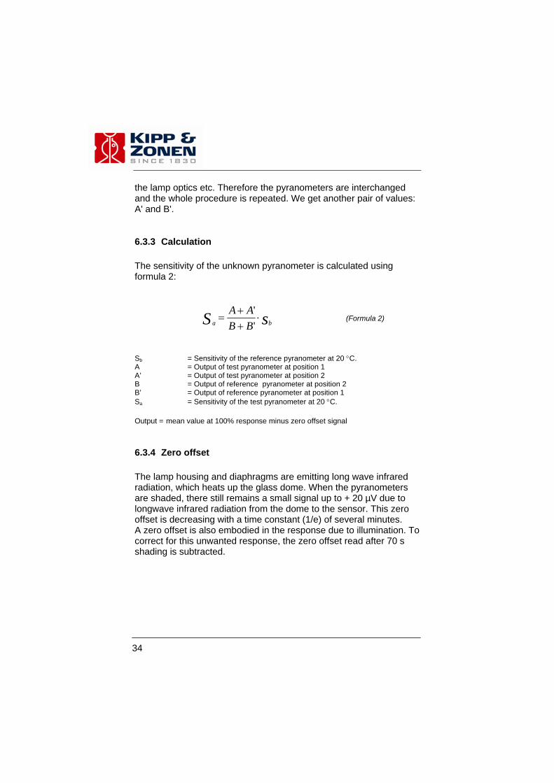
6.3.3 Calculation The sensitivity of the unknown pyranometer is calculated using formula 2:
sS ba BBAA
⋅++
=''
(Formula 2)
Sb = Sensitivity of the reference pyranometer at 20 °C. A = Output of test pyranometer at position 1 A’ = Output of test pyranometer at position 2 B = Output of reference pyranometer at position 2 B’ = Output of reference pyranometer at position 1 Sa = Sensitivity of the test pyranometer at 20 °C. Output = mean value at 100% response minus zero offset signal
6.3.4 Zero offset The lamp housing and diaphragms are emitting long wave infrared radiation, which heats up the glass dome. When the pyranometers are shaded, there still remains a small signal up to + 20 µV due to longwave infrared radiation from the dome to the sensor. This zero offset is decreasing with a time constant (1/e) of several minutes. A zero offset is also embodied in the response due to illumination. To correct for this unwanted response, the zero offset read after 70 s shading is subtracted.
35
6.3.5 Traceability to World Radiometric Reference Working reference pyranometers are maintained at Kipp & Zonen. Each reference pyranometer is characterised. Linearity, temperature dependence curve and directional response are well known. The working reference pyranometers are calibrated each year at the World Radiation Center in Davos, Switzerland, according to the component method.
6. CALIBRATION

36
37
7 FREQUENTLY ASKED QUESTIONS (FAQ’s) The most frequently asked questions are listed below. 1. Negative output during measurements? This error is related to the zero offset type A. Normally this zero offset is present when the dome has a different temperature from the cold junctions of the sensor. In practice this is always the case when there is very large and cold object close to the pyranometer. The emitted heat by the glass dome is attracted from the body (by conduction in the dome) and from the air (by convection and heat conductivity). The dome is cooling down too and will attract heat from the body by conduction and from the sensor by the net infrared radiation. The latter heat flow is opposite to the heat flow from the absorbed solar radiation and causes the well known zero depression. This negative zero offset is always present, however, hidden within the thermopile signal. 2. What is the primary entry point for humidity? The desiccant cartridge and cable gland have equal chances to transport some moisture. Also the silicon glue of the domes is not completely watertight. When care is not taken one can easily make the desiccant cartridge the primary entry point. See chapter 5 for the maintenance of the CM 4 Pyranometer. Note: Water vapour transport through the cable is also possible when
the open end of the cable at the readout device is in a humid environment.
7 FREQUENTLY ASKED QUESTIONS

38
39
8 TROUBLE SHOOTING The following contains a procedure for checking the instrument in case it appears that it does not function as one could expect. Trouble shooting: Output signal fails or shows improbable results: Check the wires, whether they are properly connected to the
readout equipment. Check the dome and the drying cartridge, they should be clear. If
water is deposited on the inside, please change the desiccant. If too much water is deposited the instrument should be dried internally.
Check the instrument impedance (500 - 2000 Ohm) Check datalogger or integrator offset by connecting a dummy
load (500 - 2000 Ohm resistor). This should give a “zero” reading.
If water or ice is deposited to the outside of the dome, clean the dome. Usually water droplets will evaporate in less than one hour. Any visible damage or malfunction should be reported to your dealer, who will suggest appropriate action.
8 TROUBLE SHOOTING

40

41
9 PART NUMBERS / SPARE PARTS / OPTIONS Description Part no. Drying Cartridge kit 0356 111 (incl. Cartridge, Cover, Rubber Ring) Silica gel refill pack 2643 951
9 PART NUMBERS / SPARE PARTS / OPTIONS

42

43
APPENDIX I PYRANOMETER CLASSIFICATION
ACCORDING TO WMO GUIDE 1996
Characteristics High quality
Good quality
Moderate quality
ISO 9060 classification Secondary standard First class Second class
Response time (95 percent response) < 15 s < 30 s < 60 s Zero offset: (a) Response to 200 W/m2
net thermal radiation (ventilated) (b) Response 5 K/h change in ambient temperature
± 7 W/m2
± 2 W/m2
± 15 W/m2
± 4 W/m2
± 30 W/m2
± 8 W/m2
Resolution (smallest detectable change) ± 1 W/m2 ± 5 W/m2 ± 10 W/m2
Stability (change per year, percentage of full scale) ± 0.8 ± 1.5 ± 3.0
Directional response of beam radiation (The range of errors caused by assuming that the normal incidence responsivity is valid for all directions when measuring, from any direction, a beam radiation whose normal incidence irradiance is 1000 W/m2)
± 10 W/m2 ± 20 W/m2 ± 30 W/m2
Temperature response (percentage of maximum due to any change of ambient temperature within an interval of 50 K)
± 2 ± 4 ± 8
Non-linearity (percentage deviation from the responsivity at 500 W/m2 due to any change of irradiance within the range 100 to 1000 W/m2)
± 0.5 ± 1 ± 3
Spectral sensitivity (percentage of deviation of the product of spectral absorptance and spectral transmittance from the corresponding mean within the range of 0.3 to 3 μm)
± 2 ± 5 ± 10
Tilt response (percentage deviation from the responsivity at 0° tilt, horizontal, due to change in tilt from 0° to 90° at 1000 W/m2 irradiance)
± 0.5 ± 2 ± 5

44
Achievable uncertainty, 95 percent confidence level Hourly totals Daily totals
3% 2%
8% 5%
20% 10%

45
APPENDIX II PT-100 SPECIFICATIONS
Temp.[°C]
Resistance [Ω]
Temp. [°C]
Resistance[Ω]
Temp. [°C]
Resistance [Ω]
-40 -39 -38 -37 -36 -35 -34 -33 -32 -31 -30 -29 -28 -27 -26 -25 -24 -23 -22 -21 -20 -19 -18 -17 -16 -15 -14 -13 -12 -11 -10 -9
84,27 84,67 85,06 85,46 85,85 86,25 86,64 87,04 87,43 87,83 88,22 88,62 89,01 89,40 89,80 90,19 90,59 90,98 91,37 91,77 92,16 92,55 92,95 93,34 93,73 94,12 94,52 94,91 95,30 95,69 96,09 96,48
-8 -7 -6 -5 -4 -3 -2 -1 0 1 2 3 4 5 6 7 8 9
10 11 12 13 14 15 16 17 18 19 20 21 22 23
96,87 97,26 97,65 98,04 98,44 98,83 99,22 99,61
100,00 100,39 100,78 101,17 101,56 101,95 102,34 102,73 103,12 103,51 103,90 104,29 104,68 105,07 105,46 105,85 106,24 106,63 107,02 107,40 107,79 108,18 108,57 108,96
24 25 26 27 28 29 30 31 32 33 34 35 36 37 38 39 40 41 42 43 44 45 46 47 48 49 50 51 52 53 54 55
109,35 109,73 110,12 110,51 110,90 111,29 111,67 112,06 112,45 112,83 113,22 113,61 114,00 114,38 114,77 115,15 115,54 115,93 116,31 116,70 117,08 117,47 117,86 118,24 118,63 119,01 119,40 119,78 120,17 120,55 120,94 121,32
46
Temp. [°C]
Resistance [Ω]
Temp. [°C]
Resistance [Ω]
Temp. [°C]
Resistance [Ω]
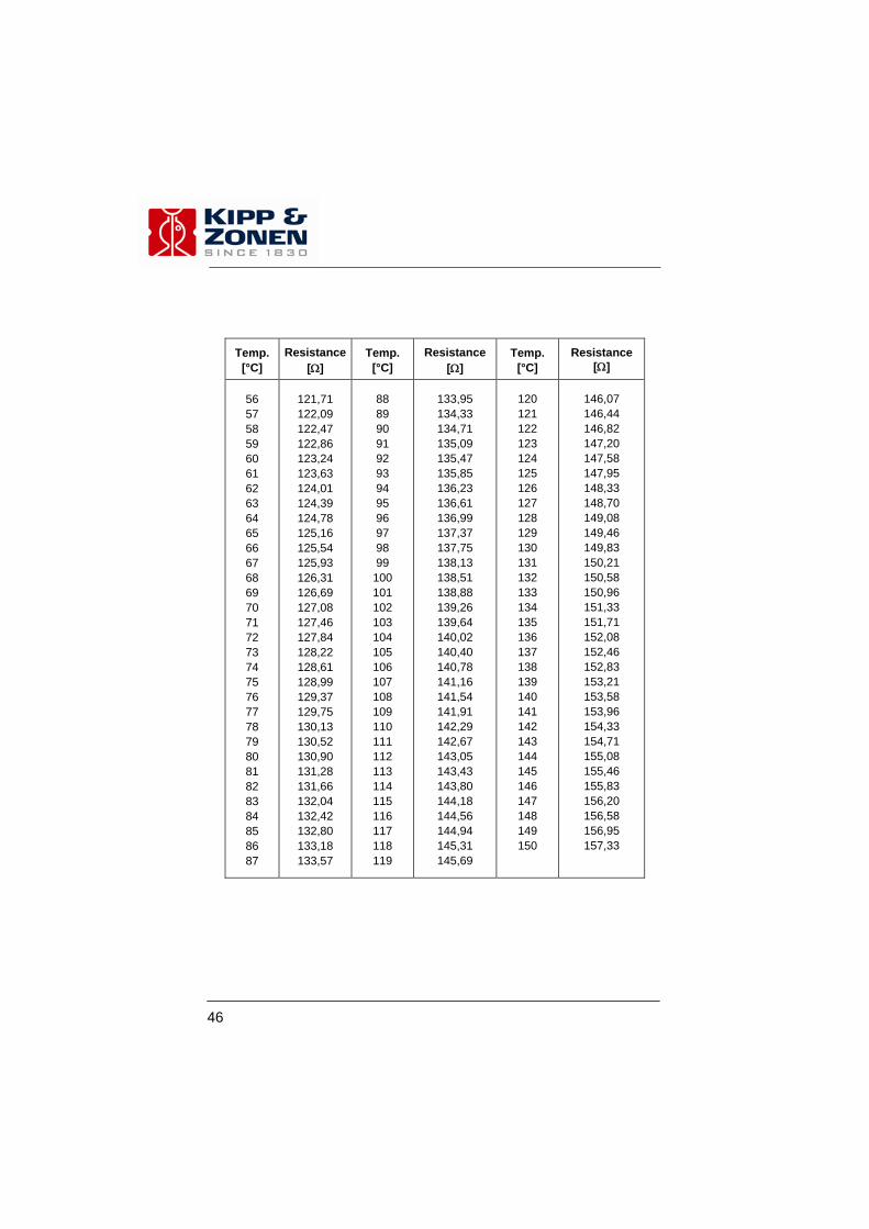
56 57 58 59 60 61 62 63 64 65 66 67 68 69 70 71 72 73 74 75 76 77 78 79 80 81 82 83 84 85 86 87
121,71 122,09 122,47 122,86 123,24 123,63 124,01 124,39 124,78 125,16 125,54 125,93 126,31 126,69 127,08 127,46 127,84 128,22 128,61 128,99 129,37 129,75 130,13 130,52 130,90 131,28 131,66 132,04 132,42 132,80 133,18 133,57
88 89 90 91 92 93 94 95 96 97 98 99
100 101 102 103 104 105 106 107 108 109 110 111 112 113 114 115 116 117 118 119
133,95 134,33 134,71 135,09 135,47 135,85 136,23 136,61 136,99 137,37 137,75 138,13 138,51 138,88 139,26 139,64 140,02 140,40 140,78 141,16 141,54 141,91 142,29 142,67 143,05 143,43 143,80 144,18 144,56 144,94 145,31 145,69
120 121 122 123 124 125 126 127 128 129 130 131 132 133 134 135 136 137 138 139 140 141 142 143 144 145 146 147 148 149 150
146,07 146,44 146,82 147,20 147,58 147,95 148,33 148,70 149,08 149,46 149,83 150,21 150,58 150,96 151,33 151,71 152,08 152,46 152,83 153,21 153,58 153,96 154,33 154,71 155,08 155,46 155,83 156,20 156,58 156,95 157,33

47
APPENDIX III LIST OF WORLD AND REGIONAL
RADIATION CENTRES World Radiation Centres Davos (Switzerland) St. Petersburg (Russia) Regional Radiation Centres Region I Africa: Cairo (Egypt) Khartoum (Sudan) Kinshasa (Zaire) Lagos (Nigeria) Tamanrasset (Algeria) Tunis (Tunisia) Region II Asia: Poona (India) Tokyo (Japan) Region III South America: Buenos Aires (Argentina) Region IV North and Central America: Toronto (Canada)
Washington (U.S.A.) Region V South West Pacific: Aspendale (Australia) Region VI Europe: Bracknell (United Kingdom) Budapest (Hungary) Davos (Switzerland) St. Petersburg (Russia) Norrköping (Sweden) Trappes/Carpentras (France)
Uccle (Belgium) MOH Hamburg (Germany

48
49
APPENDIX IV RECALIBRATION SERVICE
Pyranometers, UV-meters, Pyrgeometers & Sunshine duration sensors
Kipp & Zonen solar radiation measurement instruments comply with the most demanding international standards. In order to maintain the specified performance of these instruments, Kipp & Zonen recommends calibration of their instruments at least every two years. This can be done at the Kipp & Zonen factory. Here, recalibration to the highest standards can be performed at low cost. Recalibration can usually be performed within four weeks. If required, urgent recalibration can be accomplished in three weeks or less (subject to scheduling restrictions). Kipp & Zonen will confirm the duration of recalibration at all times. Please note that special quantity recalibration discounts are available. For your convenience we have attached three fax forms to schedule the recalibration of your instrument(s) at Kipp & Zonen.

50
51
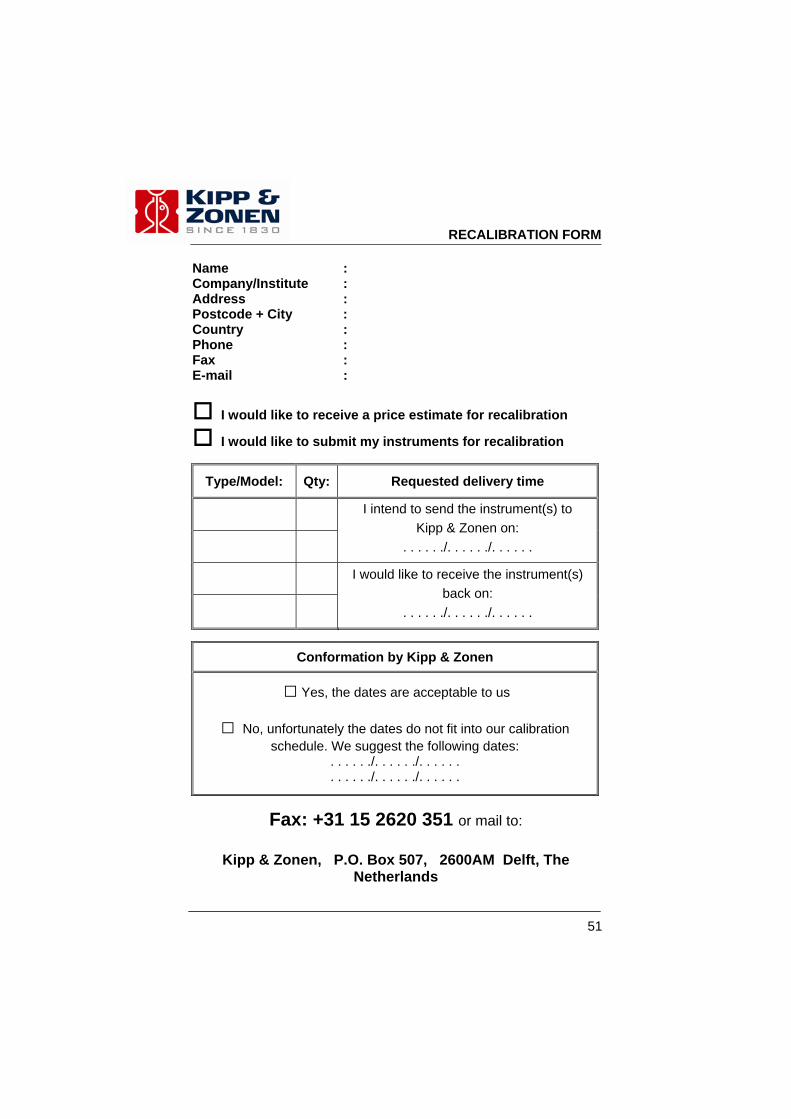
Name : Company/Institute : Address : Postcode + City : Country : Phone : Fax : E-mail :
I would like to receive a price estimate for recalibration
I would like to submit my instruments for recalibration
Type/Model: Qty: Requested delivery time
I intend to send the instrument(s) to Kipp & Zonen on:
. . . . . ./. . . . . ./. . . . . .
I would like to receive the instrument(s) back on:
. . . . . ./. . . . . ./. . . . . .
Conformation by Kipp & Zonen
□ Yes, the dates are acceptable to us
□ No, unfortunately the dates do not fit into our calibration schedule. We suggest the following dates:
. . . . . ./. . . . . ./. . . . . .
. . . . . ./. . . . . ./. . . . . .
Fax: +31 15 2620 351 or mail to:
Kipp & Zonen, P.O. Box 507, 2600AM Delft, The Netherlands
RECALIBRATION FORM

Our customer support remains at your disposal for any maintenance or repair, calibration, supplies and spares.
Für Servicearbeiten und Kalibrierung, Verbrauchsmaterial und Ersatzteile steht Ihnen unsere Customer Support Abteilung zur Verfügung.
Notre service 'Support Clientèle' reste à votre entière disposition pour tout problème de maintenance, réparation ou d'étalonnage ainsi que pour les accessoires et pièces de rechange.
Nuestro apoyo del cliente se queda a su disposición para cualquier mantenimiento o la reparación, la calibración, los suministros y reserva.
Passion for Precision
Go to www.kippzonen.com for your local distributor or contact your local sales office
HEAD OFFICE
Kipp & Zonen B.V.Delftechpark 36, 2628 XH DelftP.O. Box 507, 2600 AM DelftThe Netherlands
T: +31 (0) 15 2755 210F: +31 (0) 15 2620 [email protected]
Kipp & Zonen Asia Pacific Pte. Ltd.81 Clemenceau Avenue#04-15/16 UE SquareSingapore 239917
T: +65 (0) 6735 5033F: +65 (0) 6735 [email protected]
Kipp & Zonen USA Inc.125 Wilbur PlaceBohemiaNY 11716United States of America
T: +1 (0) 631 589 2065F: +1 (0) 631 589 [email protected]
Kipp & Zonen France S.A.R.L.7 Avenue Clément AderZA Ponroy - Bâtiment M94420 Le Plessis TréviseFrance
T: +33 (0) 1 49 62 41 04F: +33 (0) 1 49 62 41 [email protected]
SALES OFFICES