kingfisher owners’ notes - san juan sailing
TRANSCRIPT

1
Kingfisher Owners’ Notes Revised March 2019
A Note From the Owners
Welcome Aboard Kingfisher
Kingfisher is a 2005 Nordic Tug 37. Nordic Tugs are one of the most reliable, economical, and
comfortable vessels on the water. Kingfisher is equipped with all the creature comforts you expect
in a well-equipped and well-maintained vessel.
Please take time to read this manual and use it as a reference source during your charter cruise.
Spending some time now will make your checkout a breeze and your actual cruise through the
inland waters of the Salish Sea will be more enjoyable.
This is our seventh charter season as the owners of Kingfisher. We fell in love with her when we
chartered for an unforgettable family vacation eight years ago. We go to great lengths to keep her
up to date and in the best possible condition. We are pleased to be able to share Kingfisher with
you and hope you enjoy cruising the Pacific Northwest as much as we do. Let us know if you find
anything missing or have suggestions or improvements.
Bon Voyage,
Marty & Donna Shively

2
A Reminder
These notes have been prepared to give the charter captain and crew a helpful resource of
information. While the goal is to summarize information from multiple sources into a single item,
this document does not pretend to be the ultimate authority on the equipment and systems on
board. Consult the manuals provided by the various manufacturers (stored underneath the
starboard pilot house seat).
Further, the captain accepts and is the ultimate person responsible for the safety of the crew,
passengers and the vessel. It is expected that he / she is qualified to operate a vessel the size,
type and complexity of Kingfisher and has become thoroughly familiar with her prior to leaving the
dock. Good judgment and following all applicable laws during operations is fundamental to a safe
and successful experience on board this vessel and in the maritime environment.
No warranties are expressed or implied by this document.

3
Kingfisher Owners’ Notes Revised March 2019
Contents A Note From the Owners ................................................................................................... 1
Welcome Aboard Kingfisher ............................................................................................... 1
A Reminder ................................................................................................................... 2
ANCHORING AND SHORE TYING ........................................................................................... 5
Anchors & Rodes .......................................................................................................... 5
Chain Markings ............................................................................................................ 5
Windlass .................................................................................................................... 5
Rode Consideration for NW Waters .................................................................................... 5
Anchoring Process: ....................................................................................................... 5
Anchor Bridle .............................................................................................................. 6
Raising the Anchor and Washdown .................................................................................... 6
Emergency Manual Winch ............................................................................................... 7
Shore Lines (Stern Tie) .................................................................................................. 7
Using Kingfisher’s Shore Line .......................................................................................... 7
Mooring Equipment ....................................................................................................... 8
Boat Hook .................................................................................................................. 8
BBQ GRILL ..................................................................................................................... 8
BATTERIES & CHARGING .................................................................................................... 9
Batteries and Charging System Protection .......................................................................... 11
BATTERY CHARGE TROUBLESHOOTING ................................................................................. 13
BERTHS ....................................................................................................................... 14
BILGE PUMPS ................................................................................................................ 14
DECK WASH .................................................................................................................. 14
DINGHY/DAVIT ............................................................................................................... 15
AC & DC BREAKER PANELS and SHORE-POWER (DIS)CONNECT ..................................................... 17

4
DC Breaker Panel ........................................................................................................ 17
AC Breaker Panel and Shore Power (dis)Connect .................................................................. 18
Inverter .................................................................................................................... 19
Generator ................................................................................................................. 19
ELECTRONICS ................................................................................................................ 19
Chart-plotter .............................................................................................................. 20
Radar ....................................................................................................................... 20
Autopilot ................................................................................................................... 21
EMERGENCY/SAFETY ....................................................................................................... 23
ENGINE ....................................................................................................................... 23
DIESEL FUEL ................................................................................................................. 24
Filling Fuel Tanks ........................................................................................................ 25
Fuel Filters ................................................................................................................ 25
GENERATOR ................................................................................................................. 26
Generator Service ........................................................................................................ 26
HEAD AND HOLDING TANK ................................................................................................ 27
Pump-Out and Dumping ................................................................................................ 28
HEATING & COOLING ....................................................................................................... 29
REFRIGERATOR/FREEZER .................................................................................................. 29
SHOWER ...................................................................................................................... 30
STOVE ......................................................................................................................... 30
STEREO & TV ................................................................................................................ 32
THRUSTERS .................................................................................................................. 33
WATER ........................................................................................................................ 34
WATERMAKER ............................................................................................................... 34
KINGFISHER 2019 INVENTORY ........................................................................................... 36
KINGFISHER QUICK START AND OPERATION CHECK LIST ............................................................ 42
5
ANCHORING AND SHORE TYING
Anchors & Rodes: KINGFISHER is equipped with two anchors. The primary anchor is a 45lb Bruce
with 200ft of chain rode. A spare anchor with 15ft of chain and 200ft of rode is stored in the
lazarette.
Chain Markings: The rode is marked at 100’ with 10’ of yellow paint and every 50’ thereafter
with 5’ of yellow paint. The last 20’ are painted red-- STOP here!
Windlass: The anchor windlass has foot controls (up/down) at the forward end of the deck.
There is also a switch on the helm panel so the anchor can be deployed or lifted at either location.
There is a large circuit breaker for the windlass located in the forward section of the forward
cabin. It is located on the starboard side of the forward berth, tucked under the teak trim
surrounding the mattress. Another breaker switch is located on the DC electrical panel. Leave the
forward cabin breaker on and utilize the smaller breaker in the DC panel as the safety switch.
The windlass is powered by the house battery bank. The vessel’s engine should be running
whenever the windlass is used as the windlass puts a heavy load on the batteries. Use the thrusters
only to adjust the rotation of the vessel not to maneuver the vessel to a different position.
CAUTION: There is a safety issue regarding the breaker being on or off. If left on all the time (for convenience in frequent anchoring), there may be a danger of guests (children) playing with the foot controls near the windlass, and someone inadvertently having a finger or foot caught in the moving anchor chain.
Rode Consideration for NW Waters: In the Northwest, we usually do not have to follow
Chapman’s “7:1 scope minimum.” It is common for boats with all chain rodes to use a 3:1 or 4:1 or 5:1 ratio (i.e., in a depth of 30 feet you let out approximately 90 to 150 feet of chain.) In addition, we have substantial tides: 10 ft. tide swing and occasional minus tides (level below the chart datum). Do your calculations for the expected high tide level and yet be sure there will be sufficient water in your anchorage at low tide.
Anchoring Process:
1. Determine the total length of anchor rode you need to deploy. 2. Turn on Windlass power at the power panel. Release the safety line that secures the anchor. 3. Lower the anchor with foot switches on bow deck or from remote controls at the helm while
boat is backed up slowly away from anchor. 4. Slowly let out the first few feet of anchor rode taking care to manually ease the anchor over
the roller and not allow it to swing wildly. 5. Mate at the bow will monitor length of chain deployed and troubleshoot if it gets tangled. 6. Deploy the estimated length to initially hit the sea bottom plus another 5-10 feet and then
continue to pay out the anchor rode while the helmsman begins to slowly back down the
6
vessel. In essence, you are laying down a line of anchor rode on the sea bottom. When the target length is deployed, stop the windlass.
7. Skipper will continue to reverse (idle throttle) gently to test the set of the anchor. Using a combination of reverse and neutral, gently tug on the anchor until it is set.
8. Attach the “Snubber line” to the anchor rode: Secure the bitter end of the snubber line to windlass cleat. Attach hook to anchor chain beyond anchor roller. Run out enough added chain to form loop in the chain so that tension is transferred to the snubber line. Alternatively, and preferably, use the anchor bridle described and pictured below.
9. Turn off Windlass switch at the helm panel. 10. Turn off engines, shutdown the chartplotters, turn off all unneeded circuit breakers. Time
to relax and enjoy! And occasionally, check to see your position is still stabile and you aren’t slowly dragging anchor. Perform an anchor watch for about a half an hour and you should sleep well.
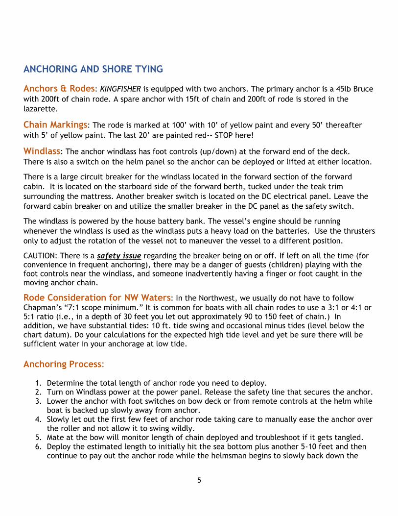
Anchor Bridle For the 2018 season we’ve added an anchor bridle (photo below) to Kingfisher to increase safety and comfort when at anchor. Once the anchor is set, hook the two loops of the bridle to the front deck cleats and the hook at the end of the bridle to the chain rode. Then let rode out until the weight and pressure of the chain rode is resting on the anchor bridle and deck cleats rather than on the windlass. The anchor bridle is stored in a bag stored in the lazarette.
Raising the Anchor and Washdown
1. Before raising the anchor, attach washdown hose (kept in a bucket in the cockpit locker) to the deck connection at the bow. To connect, push the end of the coiled hose and twist to seat it in the deck connection. Then turn on the anchor washdown and windlass circuit breakers.
2. Remove the anchor bridle or snubber line before operating the windlass. 3. Start the engine so it can be used to move the boat forward toward the anchor and manage
vessel movement once the anchor releases. Never use the windlass to pull the boat forward to where the anchor is set. (The windlass is not designed for it, it would be a large draw on the batteries, and it might cause severe damage to the attachment base of the windlass). Instead, head the boat under power toward the anchor while using the windlass to take up the slack in the chain.
4. Press the foot switch next to the windlass. Wash the chain and anchor thoroughly as you haul it in. Take your time, the anchor chain sometimes bunches up under the windlass and

7
you might need to push it down to the bottom of the chain locker to prevent the chain from jamming in the windlass.
5. Secure the anchor with the snubber line once the anchor is back in place on the deck. Snap the line through a link in the chain nearest the anchor, then tie the line to the port bow cleat. (The chain over the wildcat on the windlass should not be the only thing keeping the anchor from unexpectedly returning to the sea bottom!) After securing the anchor with a line, immediately switch the windlass breaker “off” to prevent draining the battery should the windlass system decide to short.
Emergency Manual Winch: In the event that the windlass motor fails, you can operate the
windlass manually. A handle is located in the pilothouse step on the starboard side.
Shore Lines (Stern Tie) Why? It is common to use a stern tie line in crowded / narrow anchorages (for example, in most
Desolation Sound locations, Todd Inlet at Butchart Gardens, Inati Bay near Bellingham) where there
simply isn’t enough room to have your own “swinging space”. Stern tie limits your swing and the
anchorage will support more boats in close proximity.
How? Survey the intended spot to determine depths, hazards close to shore, expected tidal swing,
etc. Then do the math to determine the total amount of anchor rode you need to deploy.
Estimate where you will drop the anchor and aim to be 50-75 ft out from shore once the total
anchor rode is deployed (of course this assumes sufficient depth and no hazards this close to
shore). Set the anchor. Then a stern line is paid out, passed around a tree or a convenient steel
ring in some locations. If sufficiently close, you can pass the bitter end of the stern tie line out to
the point on shore and back to the boat. This practice will enable a “quick release” without having
to go ashore when you’re ready to untie. To get to shore, you will need to have the dinghy down
and have your mate keep the boat toward shore with short bursts of reverse gear. Sometimes a
helpful boater already anchored will help you by taking your line to shore for you with her / his
dinghy---a considerate “good deed” that you might reciprocate some day. We have met some nice
boaters this way!
Using Kingfisher’s Shore Line 1. The 600-foot shore line is on a stainless steel reel stowed in the
lazarette and, when in use, hung on the upper deck stern rail
near the ladder to the upper deck.
2. Hand the bitter end of the shore line to the dinghy operator.
3. Once dinghy operator has run the line to shore and back to the
boat, secure both “ends” of line on one of the stern cleats. The
goal is a firm line at high tide and no tension on the remaining
line on the reel. Do not attempt to secure the line to the hand
railings, they are not strong enough to withstand the potential
forces on the line.
4. If you have run the shore line around or through a feature on the
shore, you can release the line by disconnecting the end from
the stern cleat and rolling the line on the shore line reel.

8
Mooring Equipment • Three 25-ft, typically at the bow and stern
• Two 35-ft, typically used for mid-ship spring lines
Boat Hook: A floating, telescoping boat hook is tied in the cockpit to the ladder to the upper
deck.
BBQ GRILL
We added a new Dickenson BBQ grill for the 2018 season. The BBQ grill is permanently mounted on
the aft rail. It is plumbed into a propane tank secured just below the grill within one of the fender
holders in the aft of the cockpit. Please clean the grill after use with steel brush provided. Turn
off the valve at the propane tank when not in use.
9
BATTERIES & CHARGING
All of Kingfisher’s batteries were replaced with new batteries in November of 2016.
Kingfisher is equipped with a Start Battery (the ONLY job for this battery is to start the engine), a
House Battery Bank (six 6 volt batteries wired in a series to provide 12 volt output), a Bow Battery
located in the master stateroom, which only delivers power to the bow thruster, and a Stern
Battery in the lazarette for the stern thruster and davit winch.
KINGFISHER is also equipped with a separate generator battery which gets its charge directly from
the generator.
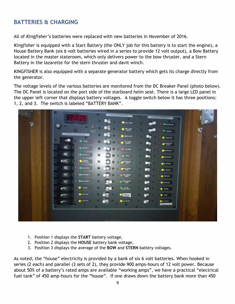
The voltage levels of the various batteries are monitored from the DC Breaker Panel (photo below).
The DC Panel is located on the port side of the starboard helm seat. There is a large LED panel in
the upper left corner that displays battery voltages. A toggle switch below it has three positions:
1, 2, and 3. The switch is labeled “BATTERY BANK”.
1. Position 1 displays the START battery voltage,
2. Position 2 displays the HOUSE battery bank voltage,
3. Position 3 displays the average of the BOW and STERN battery voltages.
As noted, the “house” electricity is provided by a bank of six 6 volt batteries. When hooked in
series (2 each) and parallel (3 sets of 2), they provide 900 amps-hours of 12 volt power. Because
about 50% of a battery’s rated amps are available “working amps”, we have a practical “electrical
fuel tank” of 450 amp-hours for the “house”. If one draws down the battery bank more than 450
10
amp-hours, one will permanently damage the batteries. Likewise, overuse of the thrusters, or davit
will draw down the available “electrical fuel tank” of the Bow or Stern Batteries.
The batteries are charged via various systems. While the engine is running, the alternator handles
the battery charging chores. It charges all batteries except the generator battery.
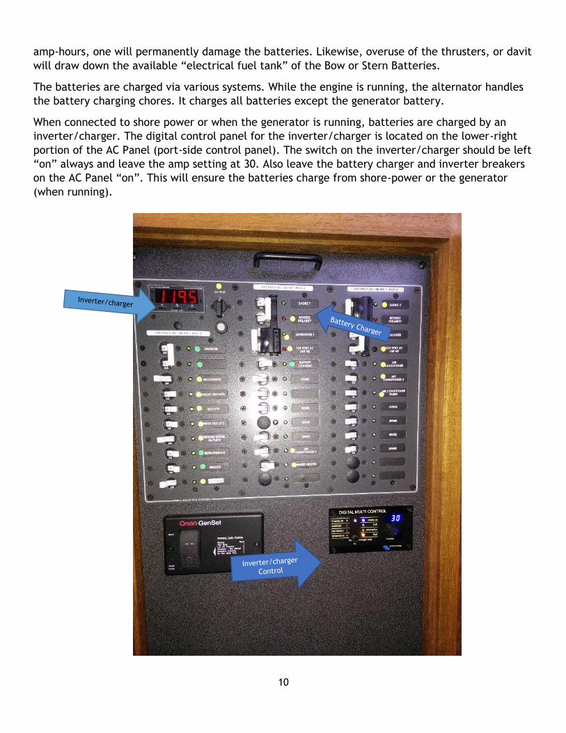
When connected to shore power or when the generator is running, batteries are charged by an
inverter/charger. The digital control panel for the inverter/charger is located on the lower-right
portion of the AC Panel (port-side control panel). The switch on the inverter/charger should be left
“on” always and leave the amp setting at 30. Also leave the battery charger and inverter breakers
on the AC Panel “on”. This will ensure the batteries charge from shore-power or the generator
(when running).
11
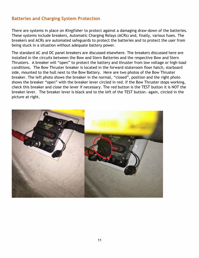
Batteries and Charging System Protection
There are systems in place on Kingfisher to protect against a damaging draw-down of the batteries.
These systems include breakers, Automatic Charging Relays (ACRs) and, finally, various fuses. The
breakers and ACRs are automated safeguards to protect the batteries and to protect the user from
being stuck in a situation without adequate battery power.
The standard AC and DC panel breakers are discussed elsewhere. The breakers discussed here are
installed in the circuits between the Bow and Stern Batteries and the respective Bow and Stern
Thrusters. A breaker will “open” to protect the battery and thruster from low voltage or high-load
conditions. The Bow Thruster breaker is located in the forward-stateroom floor hatch, starboard
side, mounted to the hull next to the Bow Battery. Here are two photos of the Bow Thruster
breaker. The left photo shows the breaker in the normal, “closed”, position and the right photo
shows the breaker “open” with the breaker lever circled in red. If the Bow Thruster stops working,
check this breaker and close the lever if necessary. The red button is the TEST button it is NOT the
breaker lever. The breaker lever is black and to the left of the TEST button—again, circled in the
picture at right.

12
There is a similar breaker for the Stern Thruster
located in the starboard side of the lazarette below
the cockpit. Here is a photo of the Stern Thruster
breaker. The windlass is powered by the house
battery bank. The windlass and the Bow Thruster, and
the davit and Stern Thruster each put a heavy load on
their respective batteries. Using them both at the
same time will quickly drain the available power. Use
the thrusters only to adjust the rotation of the
vessel not to maneuver the vessel to a different
position. The engine should be running, to support
charging of the batteries, whenever you are using
the windlass or the davit.
The Automatic Charging Relays (ACRs) are the second form of automated safeguard to protect the
batteries and devices connected to the batteries. When an ACR senses conditions in a battery bank
outside a predefined normal operating
range, the ACR “opens” the charging circuit
to that battery bank. Essentially, the ACRs
try to keep the separate battery banks
within a similar range of voltage levels. If
one of the battery banks has a significant
drop in voltage, the ACR isolates that
battery bank until it can be safely charged.
The picture here shows the ACRs mounted
to a panel on the starboard side of the
engine in the engine room. The view is
from the shelf where the house batteries
are fixed and looking to port.
The ACR at the upper left controls the
charging input from the engine alternator to the Start Battery. Once the Start Battery reaches 13v
this relay will close the circuit and allow a charge to go to the bottom left ACR and top right ACR.
The bottom left ACR allows the charge coming from the alternator to charge the House Bank and
the Bow Battery. The top right ACR allows the charge from the alternator to charge the Stern
Battery.

13
If you are plugged into shore power or have the generator
running, the bottom left ACR controls the charging input
and will charge the house bank first until it reaches 13v
and then close the circuit sending a charge to the Bow
Battery, Start Battery and Stern Thruster Battery. The
status of the ACRs is indicated by a green LED. The photo
to the left shows the LED Status Chart printed on the side
of each ACR. When the ACRs are “closed”, charging, the
LED is steady green. When the ACR is isolating a battery
bank, that ACR LED will be off or blinking green.
This information is helpful when troubleshooting charging
issues after, for example, overuse of the bow thruster that
has led to low voltage levels and open thruster breakers.
***NEVER let any battery bank go below 12 volts. Please
check the battery voltages displayed on the top left corner
of the DC panel multiple times every day to ensure the
batteries are always above 12v.***
BATTERY CHARGE TROUBLESHOOTING
If you suspect that your batteries are not charging even with the engine running or when connected
to shore power, there are steps you can take to confirm the situation and take proper action.
(NOTE – when running your engine, plugged into shore power or running the generator, all three
battery voltage meters located at the top left corner of the DC panel should all be reading 13v –
14v. If one of the banks is reading lower than 13v then there is a good chance that battery bank is
not being charged)
1. Check the charging status of the ACRs as described. If the ACRs all show a steady green LED
when the engine is running or when connected to shore power or the running generator,
then all systems are charging properly. If one or more ACR LEDs are off or blinking, then
proceed to the next step.
2. Check the condition of the Bow and Stern breakers, as described, and reset them if
necessary.
After resetting the Bow and Stern thruster breakers, check the ACR status lights again. It may take
some time (Kingfisher’s owner has seen ~30 minute delay) after resetting the breakers and with
shore power or engine running for the ACR to sense sufficient Start battery voltage and again allow
charging of the other battery banks.

14
BERTHS Kingfisher has berths for 6 people. The master stateroom has a queen berth, the starboard
stateroom has 2 bunks, and the dinette converts to a double bed. To convert the dinette, lift the
seat cushions and remove the 2 pins then slide out and re insert the pins.
Do not use the night table in the port bunkroom as a step—it is not made to carry a large load. Use
the folding step attached to the closet.
BILGE PUMPS Kingfisher has 3 bilge pumps. They are located below the front hall, below the galley, and in the
lazarette.
The circuit breakers in the DC BREAKER PANEL (position 4, 5, and 6) should remain on at all times and should be in the automatic position on Helm Control Panel.
DECK WASH There is a deck wash connection on the bow and on the starboard side of the cockpit. Sea water is
pumped through the connection using a self-coiling hose that is kept in the propane box in the
cockpit. Please use to clean the anchor chain and anchor and wash dirt overboard through deck
drains. When cleaning anchor chain please spray chain before it gets to roller to keep mud off the
deck. To use the deck wash push and twist into connection to use and then turn on the washdown
pump breaker on DC Panel.

15
DINGHY/DAVIT
The dingy is a10ft AB inflatable with a fiberglass bottom. It has a Eurohelm and 20hp Honda motor.
It really zooms!
To lower the dinghy, start by removing the cover and release the tie
downs (two) at the stern and the strap in the middle of the dinghy. The
davit arm has two positions: a lower position and an upper, or lifting
position. If the davit arm is already in the lifting position, as shown in
the adjacent photo, you are ready to move to the next step (and next
paragraph). If the davit arm is in the lower position you need to move
it to the lifting position. It’s best to do this with two people. One
person removes the bowtie cotter pin and then pulls the metal
positioning rod out of the davit base. This frees up the davit arm. The
second person then raises the davit arm to the lifting position and
holds it in place while the first person inserts the rod in the upper hole
of the davit base and secures the rod with the cotter pin. Be careful
not to drop that positioning rod!
Confirm that the two dinghy drain plugs are in place.
One is installed inside the dinghy and one is installed on
the back of the transom. The dinghy controls should be
folded down and the motor should be turned all the way
to port.
With the davit arm in the lifting position, attach the
davit hook to the rear O ring in the bridle that is
connected at four inside corners of the dinghy. Standing
at the stern, plug the davit control (stored in the
starboard step of the pilot house) into the connector at the
rear of the davit base. Use the control to raise the dinghy
while holding the stern and rotating the dinghy clockwise
as it rises. You want to line up the dinghy controls with
the red arrow on the davit arm. See Figures 1-4. As you
see in the photos, you will end up with the davit arm
swinging out over the side so that the dinghy bow is
facing to Kingfisher stern.
Lower the dinghy to the water watching so that it does
not contact the side of the boat. It is better to lower
steadily rather than starting and stopping the davit to
avoid putting unnecessary pressure on the davit. It is
helpful to have someone in the cockpit below to guide the
dinghy down to the water and grab the dinghy painter.
FIGURE 1
FIGURE 2
FIGURE 3
FIGURE 4

16
When the dinghy is on the water, unhook the davit and use the davit control to bring the davit hook
back to the top deck where you can attach the davit hook to one of the dinghy supports.
In the dinghy, unhook the bow bridle hooks and place the bridle behind the seat. It is not necessary
to detach the rear bridle hooks.
Rotate the dinghy controls up and insert the two pins to hold the controls in place. To start the
engine, pump the fuel bulb (behind the seat) until firm (and no more) then turn the key to start
the engine and let it idle for a few minutes. Do not raise the throttle lever as you can flood the
engine. If the engine does not start and you smell gas, you’ve flooded the engine and will need to
let it sit for a few minutes. The engine tilt control is on the outside of the accelerator lever.
When remounting the dinghy, make sure the dinghy is again oriented with its bow facing
Kingfisher’s stern. Detach the pins in the steering control and rotate the control down. Tilt the
engine to the up position and turn it to port. Reattach the bow bridle hooks and attach the davit
hook to the rear O ring in the bridle.
With one person on the upper deck and one in the cockpit to guide the dinghy as she raises, the
person above will use the davit control to raise the dinghy in one motion being caution not to strike
the side of Kingfisher. Reversing the procedure you used to offload the dinghy, raise the dinghy
until it is clear of the rail and rotate it and lower to the chocks. Rear chocks should be
approximately 4 inches in front of rear transom of dinghy. After the dinghy is resting on the chocks
you may move it forward or sideways to better position it on the chocks.
Before traveling, be sure to reconnect the two straps at the dinghy stern and the single strap
crossing the dinghy middle.

17
AC & DC BREAKER PANELS and SHORE-POWER (DIS)CONNECT
Kingfisher has a DC and AC Breaker Panels. The DC Panel is located on the starboard side helm seat
and the AC on the port side.
DC Breaker Panel
There is a large LED panel in the upper left corner, which shows the voltage in various battery
banks. A toggle switch, labeled “Battery Bank”, below and to the right of the LED panel has three
positions: 1, 2, and 3.
• Position 1 is the START battery bank
• Position 2 is the HOUSE battery bank.
• Position 3 is a combination of the BOW and STERN batteries (for the Thruster at the Bow
and Thruster and Davit at the Stern)
The MAIN switch provides power to all the breakers (except covered breakers). BATT 1 breaker
energizes the remote battery switch coming from the START battery bank. BATT 2 breaker
energizes the remote battery switch coming from the HOUSE battery bank. Below the LED panel is
the COVERED (for safety) circuit breakers. The nine covered breakers are labeled as follows:
1. Battery 1 2. Battery 2 3. Engine Controls 4. Bilge pump 5. Bilge pump 2 6. Bilge pump 3

18
7. Stereo 8. Step Light 9. Spare
The covered breakers are all part of the “Vital Buss”, which means they are always on. The
remaining two rows of circuit breakers are clearly labeled and switched on or off as needed.
The breakers are color-coded on both the DC and AC panels. Breakers marked in green should be left on all the time whether you are on or off the boat or on or off shore-power. Breakers marked in yellow are turned on or off depending on desired use. Breakers marked in red should be left in the off position.
AC Breaker Panel and Shore Power (dis)Connect
The AC Breaker Panel is color-coded similarly to the DC Breaker Panel. Before disconnecting and
stowing the shore power cord, turn off the individual AC breakers. Then turn off the master
breaker located on the upper portion of the breaker panel (marked below). Then turn off the
breaker at the dockside power outlet before disconnecting the shore power cord from Kingfisher.
This prevents arcing of the plug terminals.
To reverse this procedure, (as when you have returned to the dock) plug the cord into the boat’s
shore power inlet (portside, just aft of the pilot house door), then (after confirming the dockside
power breaker is “OFF”) into the dockside power outlet. Turn on the breaker at the dock outlet.
(Remember plug first, then switch – to prevent arcing). Then check the boat’s AC panel meter to
see if the polarity is OK. (If it is reversed, indicating a dangerous condition, a red light will show
Shore power
inlet
Inverter
Master
AC BREAKER PANEL

19
on the boat’s AC panel at the breaker marked Reverse Polarity—in the photo above, center, second
from top). If OK, continue to turn on the master breaker, the breakers with green markers, and
any other breakers you wish to have on.
Inverter The inverter breaker should be left “ON” at the AC Panel (see the photo above). The inverter takes
energy stored in the house battery bank and converts that DC energy to AC power so you can power
certain devices needing AC power (e.g., microwave) when you are not connected to shore power or
using the generator. The inverter powers only the breakers in the left hand column of breakers in
the AC Panel, see above photo.
Generator
In addition to these basic components, KINGFISHER has a generator to furnish AC power. The on/off
rocker switch for starting/stopping the generator is located just below the AC panel. To start the
generator, hold the rocker switch in the ON position until the generator stops.
ELECTRONICS
Kingfisher is equipped with Furuno radar and electronics, including AIS transceiver, installed in
2017. The chart plotter is a Furuno model TZ Touch 2. The radar is Furuno NXT Doppler.
Kingfisher’s MMSI for tracking via AIS systems and apps is: 338233008.
There are several breakers on the DC Breaker Panel that are activated to operate the electronics.
There are two breakers marked “Electronics” on the right column of breakers, the “Thrusters”
breaker is in the middle column and the “Autopilot” breaker is in the left column of breakers. You
can see all of these in the photo above of the DC Breaker Panel.
In the photo at left, the chart plotter is the large
display on the left. The autopilot (Furuno
NAVpilot-711C) is located to the immediate right
of the chart plotter. The multi-function display
(MFD) at the upper right is wind speed/direction
and the MFD at the lower right displays speed,
course and depth.
20
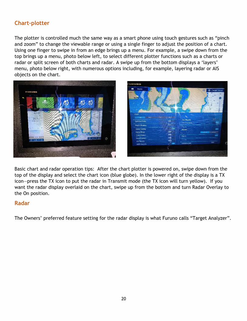
Chart-plotter
The plotter is controlled much the same way as a smart phone using touch gestures such as “pinch
and zoom” to change the viewable range or using a single finger to adjust the position of a chart.
Using one finger to swipe in from an edge brings up a menu. For example, a swipe down from the
top brings up a menu, photo below left, to select different plotter functions such as a charts or
radar or split screen of both charts and radar. A swipe up from the bottom displays a ‘layers’
menu, photo below right, with numerous options including, for example, layering radar or AIS
objects on the chart.
Basic chart and radar operation tips: After the chart plotter is powered on, swipe down from the
top of the display and select the chart icon (blue globe). In the lower right of the display is a TX
icon—press the TX icon to put the radar in Transmit mode (the TX icon will turn yellow). If you
want the radar display overlaid on the chart, swipe up from the bottom and turn Radar Overlay to
the On position.
Radar
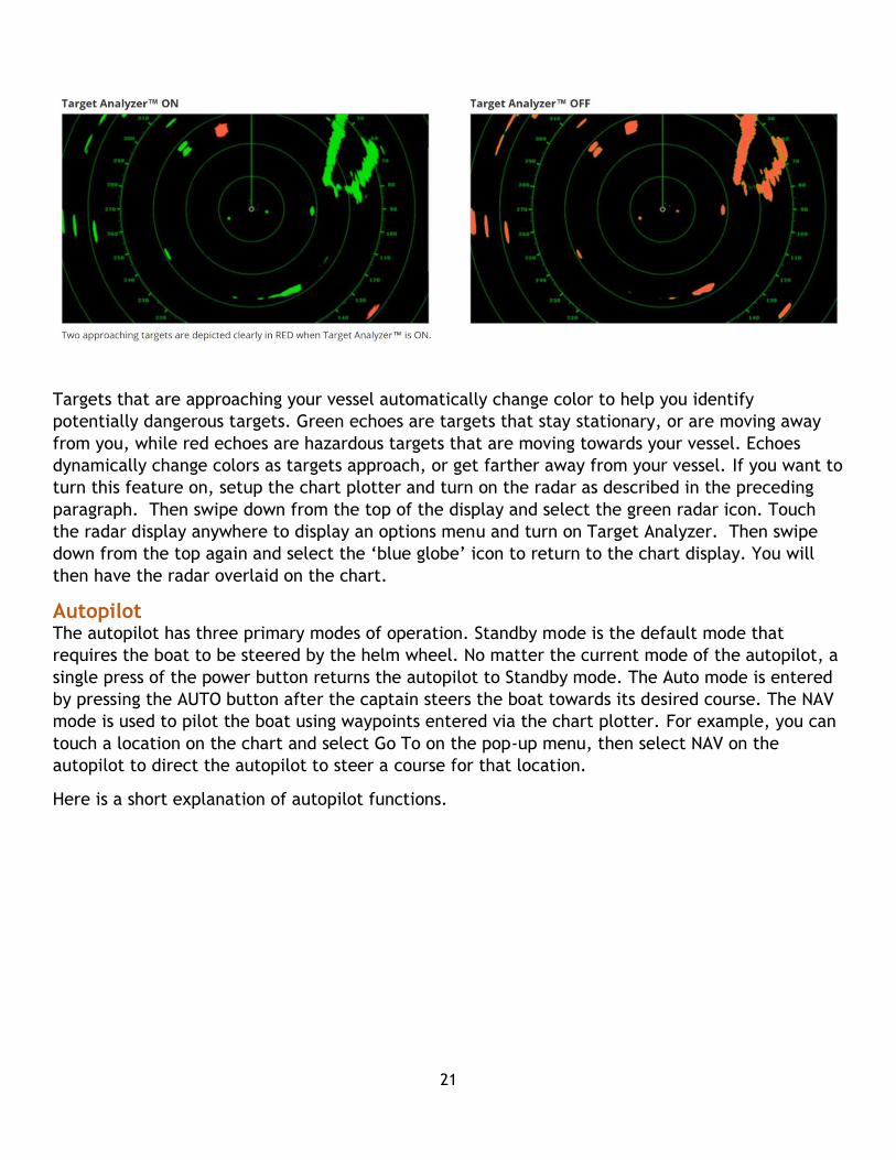
The Owners’ preferred feature setting for the radar display is what Furuno calls “Target Analyzer”.
21
Targets that are approaching your vessel automatically change color to help you identify
potentially dangerous targets. Green echoes are targets that stay stationary, or are moving away
from you, while red echoes are hazardous targets that are moving towards your vessel. Echoes
dynamically change colors as targets approach, or get farther away from your vessel. If you want to
turn this feature on, setup the chart plotter and turn on the radar as described in the preceding
paragraph. Then swipe down from the top of the display and select the green radar icon. Touch
the radar display anywhere to display an options menu and turn on Target Analyzer. Then swipe
down from the top again and select the ‘blue globe’ icon to return to the chart display. You will
then have the radar overlaid on the chart.
Autopilot The autopilot has three primary modes of operation. Standby mode is the default mode that
requires the boat to be steered by the helm wheel. No matter the current mode of the autopilot, a
single press of the power button returns the autopilot to Standby mode. The Auto mode is entered
by pressing the AUTO button after the captain steers the boat towards its desired course. The NAV
mode is used to pilot the boat using waypoints entered via the chart plotter. For example, you can
touch a location on the chart and select Go To on the pop-up menu, then select NAV on the
autopilot to direct the autopilot to steer a course for that location.
Here is a short explanation of autopilot functions.

22
Operators Guides for the chart plotter
and the autopilot are stored with the
Charter Guest Reference Manual aboard
Kingfisher. The same information and
more is available at the Furuno
website:
- Chart plotter Operator’s Guide (brief overview of functions)
http://www.furunousa.com/ProductDocuments/TZTL12F_15F%20Operator's%20Guide%20ver%20
A.pdf
- Chart plotter Operator’s Manual (complete, detailed manual)
http://www.furunousa.com/ProductDocuments/TZTL12F_15F%20Operator's%20Manual.pdf

23
EMERGENCY/SAFETY Kingfisher is equipped with modern safety equipment. Life Jackets are located in the cabinet next to the settee in portside locker in the salon. Please try on and adjust to size before departure. A Life Ring/Sling is located on the stern rail. An automatic fire-suppression system is installed in the engine room. There is a control for the fire-suppression system at the help which should be left ‘on’. There are 3 Fire Extinguishers located:
1 Salon
2 Engine Room
3 Master Suite
There is a flare kit located in the aft locker portside. The EPIRB is attached to the port helm seat.
Flashlights are located in the helm drawer. First Aid Kit is located under port seat in Pilot House.
ENGINE Refer to the Kingfisher QUICK START laminated card for engine room checklist. This procedure should be performed daily before departure. The Kingfisher QUICK START is printed on a laminated card located in the chart table drawer.
The 380HP Cummins engine aboard Kingfisher is designed with a maximum RPM of 3000 rpms.
These engines are intended to operate at a maximum operating/cruising RPM of 80% of maximum
output or, in this case, 2400 RPMs. The engine should not be operated at this 80% of maximum for
more than one hour per day.
24
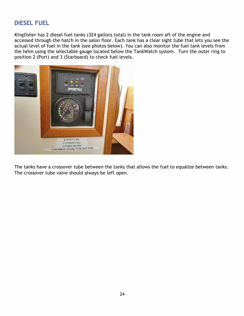
DIESEL FUEL Kingfisher has 2 diesel fuel tanks (324 gallons total) in the tank room aft of the engine and accessed through the hatch in the salon floor. Each tank has a clear sight tube that lets you see the actual level of fuel in the tank (see photos below). You can also monitor the fuel tank levels from the helm using the selectable gauge located below the TankWatch system. Turn the outer ring to position 2 (Port) and 3 (Starboard) to check fuel levels.
The tanks have a crossover tube between the tanks that allows the fuel to equalize between tanks.
The crossover tube valve should always be left open.

25
Filling Fuel Tanks
Deck fittings are clearly marked FUEL, WATER, or WASTE, and the deck fittings are removed with a special spanner wrench located in port helm step (and a second one in the chart table drawer). Filling the fuel tanks can be a bit messy unless care is taken. Keep a rag or paper towels readily at hand when filing the tanks. Clean any fuel spill off the deck as it is very slippery and hazardous. Although there is a crossover tube connecting the tanks, you will need to fill each tank separately to get both full because the crossover equalizes the tanks overtime but not in the short time it takes to fill the tanks. If you fill the tank to the very top, then you run the risk of overfill spilling out of the fuel tank
vent, and down the hull of the boat into the water. THIS IS NOT GOOD. It is a good practice to
have someone watch the sight tube on the fuel tank and alert the person
topside when it nears the top. Immediately replace
fuel fill cap to prevent contaminates from entering.
It is very important to have clean fuel for the
engine.
Fuel Filters Kingfisher has dual RACOR fuel filters. These are
the first line of defense against contamination,
whether water or dirt. The filters are mounted to
the wall at the back of the engine room, portside.
They have glass bowls so a visual check for water or
contamination is possible. This should be a regular
inspection by the operator to prevent fuel problems
while underway. There is a lever on the dual filter
manifold, allowing flow through both, or either
single filter. The selector lever should be positioned to one or the other filter, not both. This will
allow one filter to collect contaminants and leave the other one ready to use when you change the
dirty filter. The fuel filters are shown in the photo at right
where the left filter is currently active, as indicated by the
direction of the selector lever. If dirt or water is apparent in
the glass bowl, the operator can switch the lever over to the
other filter. If this is necessary, the operator should contact
San Juan Yachting or the maintenance pro to discuss.
If the vacuum gauge mounted between the filters reads
between 7 and 10 for the filter being used switch to the other
filter. If it becomes necessary to replace a filter please
contact the maintenance pro or San Juan Yachting for assistance.
PORT FUEL TANK
AND SIGHT TUBE STARBOARD FUEL TANK AND
SIGHT TUBE

26
GENERATOR Kingfisher is equipped with an ONAN 9 KW generator. The Generator has a remote switch panel
located on the AC Breaker Panel on the side of the port helm seat, see photo to left.
The generator switch panel as a large, rubber-coated rocker switch. The top is labeled START and the bottom is labeled STOP. This switch also has an indicator light that indicates status and various error conditions printed next to the rocker switch. When you push and hold the rocker switch in the ON position the indicator light blinks yellow while the generator is in preheat mode. When the generator starts, release the rocker switch and the light will turn to green. If the unit does not start, or shuts down, for any reason, then the service light blinks a numerical code; for example 2 blinks means low oil pressure 4 blinks means failure to start within a specified time limit. The actual codes are in the manual and also on the plate attached to the generator.
Generator Service: A generator has a diesel engine requiring the
same care as the main engine. You have to remove the sound shield
to check the oil level. The generator’s diesel engine uses coolant just like the main engine. Check
it routinely. Always check for evidence of leaking oil, fuel, or coolant.
If the generator fails to start at the remote switch,
check that the DC breaker on the genset is “ON”, see
photo to the right.

27
HEAD AND HOLDING TANK The head has a VACUFLUSH freshwater toilet that flushes into a 32 gallon holding tank. The vacuum
pump is located in the engine room and runs for approximately 30 seconds after each flush. An
indicator panel is mounted adjacent to the toilet, and has an on/off switch, and indicator LEDs to
show its status. READY (green) or WAIT (red). Lift up the foot lever to “pre fill” the bowl if there is
not water in the bowl or you need additional water. Step down on the foot lever to empty the bowl
and lift foot quickly. If foot lever is released before waste is clear of bowl do not flush again until
vacuum pump stops running and red light goes out. If vacuum pump runs longer than one minute
raise foot lever and push down again.
DO NOT PUT ANYTHING DOWN THE TOILET THAT HAS NOT BEEN EATEN. Small Ziploc bags are
stored in the cabinet below the sink. You can minimize paper going down the head by sealing
soiled paper in a Ziploc bag and dropping it in the trash.
The toilet discharges into the WASTE TANK. The tank is located under the engine pan, and the level of waste is measured by a TANK WATCH system, with sensors inside the tank itself. The indicator panel is below the helm along the stairs to the staterooms. To activate the indicator panel, turn on the macerator breaker on the DC panel. LEDs show the level of the tank fluid: Green means empty, Yellow means Low, Orange means half full, and Red means full. The toilet should not be used when the indicator light is red, until the waste tank is emptied. The round gauge below the TankWatch panel indicates Fuel (Port and Starboard Tanks) and fresh
water level by rotating the outer ring of the gauge to different positions. The gauge is activated by
the “Pump Gray Water” breaker on the DC panel.
28
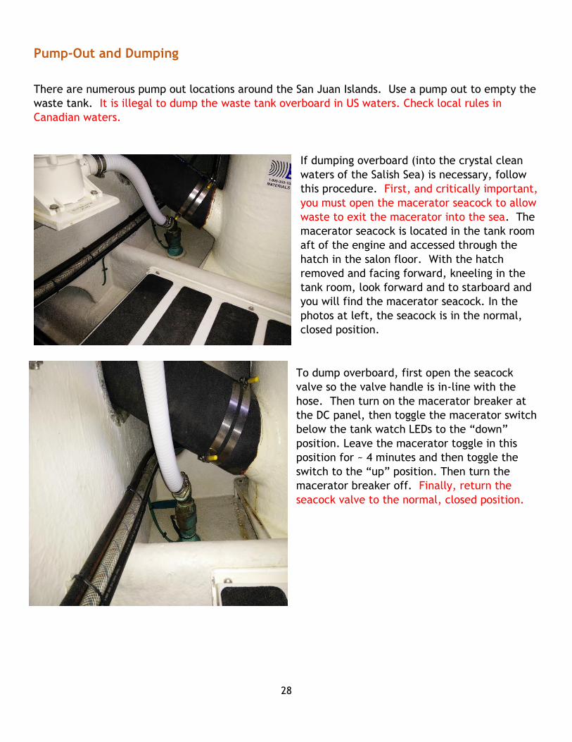
Pump-Out and Dumping
There are numerous pump out locations around the San Juan Islands. Use a pump out to empty the
waste tank. It is illegal to dump the waste tank overboard in US waters. Check local rules in
Canadian waters.
If dumping overboard (into the crystal clean
waters of the Salish Sea) is necessary, follow
this procedure. First, and critically important,
you must open the macerator seacock to allow
waste to exit the macerator into the sea. The
macerator seacock is located in the tank room
aft of the engine and accessed through the
hatch in the salon floor. With the hatch
removed and facing forward, kneeling in the
tank room, look forward and to starboard and
you will find the macerator seacock. In the
photos at left, the seacock is in the normal,
closed position.
To dump overboard, first open the seacock
valve so the valve handle is in-line with the
hose. Then turn on the macerator breaker at
the DC panel, then toggle the macerator switch
below the tank watch LEDs to the “down”
position. Leave the macerator toggle in this
position for ~ 4 minutes and then toggle the
switch to the “up” position. Then turn the
macerator breaker off. Finally, return the
seacock valve to the normal, closed position.

29
HEATING & COOLING Kingfisher has two heating systems: a set of three reverse cycle heating\cooling units and a diesel
furnace. See the photo below of one (of three) reverse cycle heating\cooling unit controls and the
diesel furnace control.
The reverse cycle heating\cooling system (aka the Air
Conditioners) is powered by shore or generator power.
Each of the three reverse cycle heating\cooling units
is controlled by a separate thermostat, one in the
master stateroom and two in the galley/salon. These
units can be used to heat or cool Kingfisher depending
on conditions. With only one shore power cord
attached, you will only be able to run one zone at a
time. Each unit is controlled by a breaker on the AC
panel. Note: In addition to turning on the breaker(s)
for the desired heat/cooling unit, you must turn on
the breaker for the Air Conditioner Pump—also on the AC panel. The AC Pump has a separate
seacock that must be opened before turning on the AC Pump. You will find the seacock in the
engine room, on the starboard side forward (lift the wooden step and you will see it below) When
not on shore-power and using the generator, you can use all three AC units at one time.
Kingfisher’s Owners have found that, in addition to the rare hot summer day, running an air
conditioner on a cool, damp day can help remove moisture from the cabin and keep the fog from
forming on the inside of the pilot house windows.
The diesel furnace can be used to heat Kingfisher without shore or generator power. The furnace
draws from the same diesel fuel supply as the main engine and generator. The simple control for
the diesel furnace is shown in the lower half of the photo. Slide the power switch to ON and set the
temperature to the desired level.
REFRIGERATOR/FREEZER The refrigerator and freezer are wired to use either 12volt DC power or 110volt AC power when
available. The refrigerator is located in the forward portion of the Galley and the freezer is in the
aft Galley. When 110 volt AC power is available, the fridge/freezer automatically selects that
option to save battery power. When connected to shore power, make sure the refrigerator and
freezer breakers are turned ON at the AC BREAKER PANEL. When not connected to shore power,
make sure the refrigerator and freezer breakers are turned ON at the DC Breaker Panel.
30
SHOWER Before using the shower, be sure the Fresh Water Pump and Pump Gray Water switches are on at
the DC BREAKER PANEL. Gray water from the shower goes into a holding tank and is automatically
pumped overboard with a standard bilge pump. If you are at a marina location where it is not
advisable to discharge gray water, you may shut off the pump gray water at the panel. The tank
only holds 9 gallons so don’t overfill.
Hot water is provided by an electric water heater and by a heat exchanger from the engine. You
automatically have hot water if the engine is running and it will stay hot for quite a while after the
engine is turned off. It is a good time for showers while the water is still hot so you don’t have to
run the generator. When connected to shore power or using the generator be sure the Water
Heater breaker is ON at the AC BREAKER PANEL.
Remember to conserve water when showering; turn the shower off when applying soap then rinse.
STOVE Kingfisher has a three burner propane stove with oven.
Propane Safety – Many boaters have been wary about having propane appliances abroad. Over the
years, many improvements have been made in propane systems, so that you find more and more
boats with a propane cooking range installed.
Safety Measures
a. The tank is located outside the cabins, and below the doors and windows of the cabins.
This is so that any gas leaks do not waft back into the interior of the boat. Nordic Tugs
installs the tanks in a locker in the cockpit, vented so leaking fumes, if any, go overboard
through vents in the lower corner of the tank locker.
b. There is a main valve on the tank, to manually turn off the gas when not in use.
c. Next is a pressure gauge which is also located in the propane locker. The purpose of the
gauge is it is to test the system for leaks. The test is made at installation, and should be
done by the boat operator routinely (weekly is often recommended) after that. NOTE:
The pressure gauge can also be utilized as a rough measure of remaining fuel in the tank.
Readings below 40psi indicates the need for a refill, but since this reading varies in hot or
cool temperatures, measure how much fuel is added to fill the tank, extrapolate what
reading works best, (e.g. 38psi instead of 40) in your conditions.
d. The pressure regulator, under the gauge, is set to limit the pressure of the gas flowing to
the appliance.

31
e. The high-flow valve, upstream of the regulator, checks the amount of gas flow if the
regulator fails for any reason.
To use the propane stove, the main valve on the propane deck needs to be
open. Next, the propane breaker on the DC panel needs to be “ON”. Then,
below the DC panel is the control for a solenoid (photo) that controls the flow
of propane: push the “on” button on the solenoid control. Now propane should
be delivered to the stovetop. You may need to open one of the stovetop burner
controls for 10 or 20 seconds before propane extends through the system to the
stove and lights.

32
STEREO & TV
Kingfisher is equipped with Bose speakers and a Pioneer Stereo mounted above the chart table in
the pilot house. The Pioneer is equipped for AM/FM and Satellite (Sirius) radio as well as CDs. You
can also stream music from your Bluetooth-equipped device to the Pioneer stereo.
The Pioneer stereo is also the DVD player for the LG TV
mounted in the hinged cabinet above the galley counter.
In the photos below you can see the TV cabinet closed
(left) and open (right).
To watch a DVD, unlock the two latches and lower the
screen (careful, it’s heavy) into the viewing position.
Power to the screen is provided by turning on the
appropriate circuit breaker (AC breaker panel, left-most
bank of breakers, the bottom breaker, marked “TV
Outlet”). The LG remote control turns on the screen and is
used to set the input. Select the AUX mode from the main screen of the Pioneer stereo and use the
Pioneer remote control to set volume and Play/Pause. There is a collection of DVDs in a holder
stored in the cabinet below the book rack in the salon.

33
THRUSTERS
Kingfisher is equipped with Bow and Stern Thrusters. There are two controls for the thrusters. The primary control is at the lower left of the control station, pictured here. The second control is a remote, hand-held device that should be kept in the chart table drawer. To use the thrusters first turn the Thrusters breaker, located on the DC breaker panel, “on”. Then simultaneously depress the two ON buttons on the thruster control, left. A green light on the thruster control indicates the thrusters are ready to use. The thrusters should be used in short bursts and only to rotate the vessel. They should not be used to maneuver the vessel, for example, for finding the ‘right’ spot to drop anchor, to pick up a buoy or to maneuver through a marina. Over-use of the thrusters will quickly deplete the thruster batteries and leave you without their valuable assistance.
See the section on Batteries and Charging for more information about batteries and circuit breakers related to the thrusters.

34
WATER Kingfisher has a 150 gallon fresh water tank located in the tank
room aft of the engine and accessed through the hatch in the salon
floor. The gauge to check the water level is located at the helm,
below the “Tankwatch” panel. The gauge is activated by the
“Pump Gray Water” breaker on the DC panel. Turn the outer ring
of the selectable gauge to position 5 to view the water tank level.
See Section 14 for a photo of the water level gauge. There is also a
sight tube under the salon sole (look aft and port and see photo).
Open the red handle valve to read and then close the valve as it
might suck air into the water tank if left open.
The electric water pump will
pump variable quantities of
water, based on demand. The water pump comes on
automatically whenever a faucet is turned on.
To fill the water tank locate the deck fitting marked “WATER’
at the starboard aft. The spanner wrench to open the plate is
located in the port helm step or chart drawer. Connect the
fresh water hose located in the lazarette to the domestic water supply. Let the water run
overboard for a minute or two to wash any contaminated water from the hose. Do not use the
marina water hose to fill the water tank-you don’t know where it has been. Fill until water comes
out the overflow below the deck fill. Tighten the plate immediately and return spanner wrench.
WATERMAKER
A watermaker was added to Kingfisher in 2019. It is not available for charter use except for long-
term charters or for an extra fee and, in any event, only by prior agreement with San Juan
Yachting.
Sight Tube

35
36
KINGFISHER 2019 INVENTORY
THE FOLLOWING IS A LIST OF THE MAJOR INVENTORY ITEMS ON Kingfisher AND THE LOCATIONS
THAT THE ITEMS CAN BE FOUND.
If you find that the locations listed below are not the most convenient for your needs, feel free to
relocate items during your charter. However, please return all items to their original location at
the end of your charter to make it easier for San Juan to inventory and restock for the next
charter guest. Thank you!
HELM
Shelf above controls
-Annotated Chart 1841, Annotated Canadian Charts 3441, 3442, 3443 (rolled in tube)
Helm Drawer
- 2 dinghy keys on floats
- 2 cabin keys on floats
- 2 Engine keys on floats
- Parallel rule, 6”dividers, 24”straight edge w/compass dial
- Knife
- Thruster remote
- Pioneer Radio remote
- Furuno remote
- Pens and notepads
- Flashlight (2)
- Ports and Passes guide
- Tidelog
- Floating VHF transceiver and charger
- Pad lock
- Extra batteries
- Playing cards
- Star chart
- Deck key
- Waterproof chart book (San Juan Islands)
- Guest book
- Second stateroom keys on float
- Scotch tape
- PFD re-arming kit
- Handheld compass
- Shellfish gauge
- Yeti cooler lock key
37
Helm Seat Compartment
- Boat Owners Manual
- Engine, Generator, and Gear Manual
- Expandable file folder with misc equip operating instructions
- Cummins’s Captain’s Briefing Manual
- Furuno electronics and auto-pilot quick start guide
- Windshield cover
Passenger Seat Compartment
- Cruising guides: Waggoneers, Gunkholing in San Juans, Dreamspeaker: San Juans and
Gulf Island and other reference books (or on map table)
- Waterproof Maptech Chartbook of San Juan Islands (or on map table)
- Current Atlas and Companion Charts
- Container with spare light bulbs, small hose clamps, nuts and bolts
- West Marine binoculars
- Sewing kit
Starboard Helm Door Step
- Battery float charger
- Davit controls
- Flyswatter
- Windlass assist bar
- Temporary dinghy lights
Port Helm Door Step
- First Aid Kit
- Extra Bandages
- Spanner Wrench and Deck Key
- Disposable gloves
Starboard Arm Rest
- Door Screen
- Window and door covers
Port Arm Rest
- Door Screen
38
- Window and door covers
FORWARD STATEROOM
- 2 pillows
- Comforter
- Blanket
- Mattress pad
SECOND STATEROOM
- 2 pillows
- 2 comforters
- 2 blankets
- 2 mattress pads
- Small extension cord with additional electric plug (in hanging locker)
GALLEY/SALON
The galley has a refrigerator, freezer, three burner propane stove with oven, and microwave.
There are two rugs. The LG TV is mounted in the hinged cabinet above the galley counter (the DVD
player is a part of the Pioneer Stereo in the helm electronics).
- Flatware service for 8
- 8 wine glasses
- 8 water glasses
- 8 steak knives
- Dinnerware service for 8
- 4 small garnish dishes
- One rectangle ‘cheese’ plate
- Large spoon
- Large chef’s knife
- Large bread knife
- Paring knife
- Can/bottle opener
- Cork screw
- 2 cheese cutters
- Cheese grater
- Garlic press
- Pancake turner
- Rubber spatula
- Tongs
- Measuring cups
- Peeler

39
- Whetstone or steel
- Plastic cutting board
- Medium serving bowl
- Small mixing bowl
- Large mixing bowl
- 2 plastic storage containers
- 2 frying pans (8” and 10”)
- 2 saucepans (1 qt and 2 qt)
- Plastic juice container
- Oven casserole dish with cover
- Broiler pan
- 2 wooden spoons
- 2 silicone pot holders
- Dish drying towel (in drawer)
- Drip coffee pot
- Coffee press with thermal container
- Tea kettle
- Paper towel stand
- Colander
Settee (under)
- Tool bags and socket set
- Power extension cord
- Vacuum Cleaner (handle is broken, works better as handheld vacuum)
Bookshelf
-Various guidebooks and local information
Cabinet by Stern Door
- 7 self-inflating Mustang personal flotation devices (PFDs)
- Misc buckets
- Orange container with flares and other survival items
- Porthole screens
- Windlass cover
Cabinet under Sink
- Misc cleaning supplies
- Trash container
40
- Dust pan and brush
- Crab pot with lid
- Dish drying rack
Cabinet above Settee
- US and Canada flags
- DVD collection in black holding case
- TV remote
- Folding thermal cooler
- Rear door cover
HEAD
- Waste basket
- Toilet brush
Bring a 17x24 inch bathmat (or two to rotate when one is wet) if it would make your stay more
pleasant. This is the same size as a hand towel.
LAZERETTE
- 50 ft. freshwater hose
- Deck brush
- Chamois mop
- Spare anchor with chain and rode
- Extra line(s)
- Manual bilge pump
- Crab trap
- Anchor Bridle in storage bag
DECK
- Dickenson BBQ Grill and cover
- Propane tank and hose for BBQ in fender storage bay
- Boat hook attached to ladder
- Mop attached to ladder
- 6 black fenders, 2 orange fenders
- Door mat
- Large YETI ice chest, 4 folding deck chairs (upper deck)
- 600’ stern line and cover
- Life Sling
Propane locker
- Deck wash water hose and nozzle
- Propane tank

41
- Chamois
- Dinghy gas can
ENGINE ROOM
- Plastic container of absorb mats, rags, and misc supplies
- Containers of engine oil, gear oil, wiper fluid, distilled water
- Battery water filler and misc funnels
- 4 containers of gen set, engine, Racor filters, and impellers
42
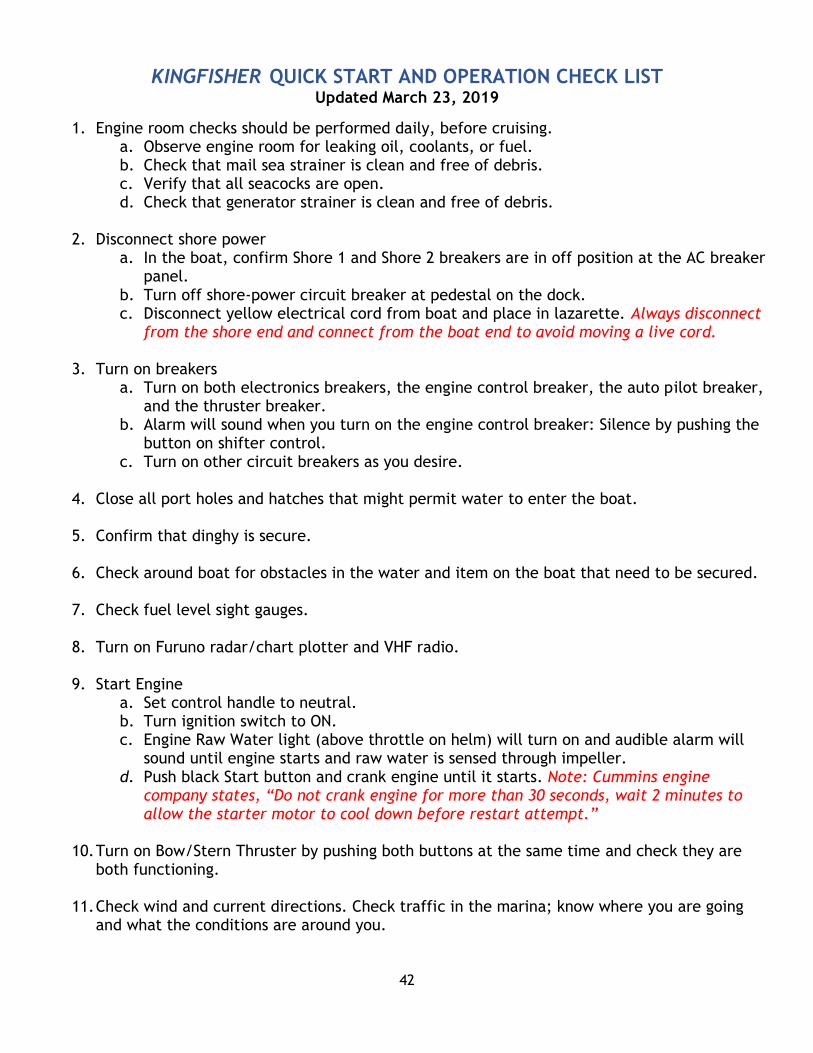
KINGFISHER QUICK START AND OPERATION CHECK LIST Updated March 23, 2019
1. Engine room checks should be performed daily, before cruising. a. Observe engine room for leaking oil, coolants, or fuel. b. Check that mail sea strainer is clean and free of debris. c. Verify that all seacocks are open. d. Check that generator strainer is clean and free of debris.
2. Disconnect shore power
a. In the boat, confirm Shore 1 and Shore 2 breakers are in off position at the AC breaker panel.
b. Turn off shore-power circuit breaker at pedestal on the dock. c. Disconnect yellow electrical cord from boat and place in lazarette. Always disconnect
from the shore end and connect from the boat end to avoid moving a live cord.
3. Turn on breakers a. Turn on both electronics breakers, the engine control breaker, the auto pilot breaker,
and the thruster breaker. b. Alarm will sound when you turn on the engine control breaker: Silence by pushing the
button on shifter control. c. Turn on other circuit breakers as you desire.
4. Close all port holes and hatches that might permit water to enter the boat.
5. Confirm that dinghy is secure.
6. Check around boat for obstacles in the water and item on the boat that need to be secured.
7. Check fuel level sight gauges.
8. Turn on Furuno radar/chart plotter and VHF radio.
9. Start Engine
a. Set control handle to neutral. b. Turn ignition switch to ON. c. Engine Raw Water light (above throttle on helm) will turn on and audible alarm will
sound until engine starts and raw water is sensed through impeller. d. Push black Start button and crank engine until it starts. Note: Cummins engine
company states, “Do not crank engine for more than 30 seconds, wait 2 minutes to allow the starter motor to cool down before restart attempt.”
10. Turn on Bow/Stern Thruster by pushing both buttons at the same time and check they are both functioning.
11. Check wind and current directions. Check traffic in the marina; know where you are going
and what the conditions are around you.

43
12. Boat Operation a. Warm up by advancing throttle to 1000rpms when clear of marina. b. Operate engine no faster than 1400rpm until the coolant temperature reaches 140
degrees. c. Operate the engine at any speed after reaching normal operating temperature of 172-
178 degrees. d. The 380HP Cummins engine aboard Kingfisher is designed with a maximum RPM of
3000. These engines are intended to operate at a maximum operating/cruising RPM of 80% of maximum output, or, in this case 2400 RPMs.
e. If you are operating at the maximum RPMs (2300-2400 rpms), do so for only one hour out of eight.
f. The following table provide some information about fuel consumption and speed at various engine RPMs
RPM’s
Fuel Consumption
Speed (depends on currents,
too)
1300 1.6 gal per hour ~8 kts
1400 2 gal per hour ~8 kts
1600 3 gal per hour ~8.5 kts
1800 4.5 gal per hour ~9.5 kts
2400 10.7 gal per hour ~11.5 kts
13. Returning to Dock
a. Place fenders on docking side of boat. b. The engine cool down period before shutting the engine down is at least 5 minutes at
slow speeds or at idle. c. When docked and the mooring lines are secure, shut off the engine. d. Turn off power to instruments.
14. Reconnect to Shore-power
a. Confirm that Shore-power switches are turned OFF at the AC breaker panel. b. Re-attach the power cord to the boat, insert the plug, turn and tighten the ring. c. MAKE SURE THE DOCK POWER SOURCE BREAKER IS IN OFF POSITION, then connect the
power cord to the dock power source. After connected, turn on the dock breaker. d. Turn on shore power breaker at AC Breaker panel. e. Turn on desired AC breakers. Battery Charger, refrigerator, freezer, etc.
15. Closing the boat
a. Close the appropriate windows and hatches. b. Lock all doors. c. On the deck, check the position of all fenders and see that mooring lines are secure.
The furnace vent is port, mid ship, and marked with a red line. Do not place a fender in this spot.